
USE, INSTALLATION AND
MAINTENANCE MANUAL
KEYLESS-SYSTEM
Keyless-System-ENG-MUIRev. - , Edition 01.2026

KEYLESS-SYSTEM
TABLE OF CONTENTS
ENG
Copyright Cobo Spa. All rights reserved. Contents subject to change without notice. 2
TABLE OF CONTENTS
1 GENERAL INFORMATION ...................................................................... 3
1.1 Aim of the document .............................................................................. 3
1.2 Recipients ................................................................................................ 3
1.3 Symbols and safety warnings used in the document ......................... 3
1.4 Regulations.............................................................................................. 4
2 SAFETY INSTRUCTIONS ........................................................................ 6
3 FUNCTIONAL SAFETY............................................................................ 6
4 FEATURES AND FUNCTIONALITIES..................................................... 7
4.1 Intended uses .......................................................................................... 8
4.2 Communication scheme......................................................................... 9
4.3 Connector and pinout............................................................................. 10
4.3.1 Ecu Keyless ....................................................................................................... 10
4.3.2 Antenna-ext........................................................................................................ 11
4.4 Ecu Keyless electrical connection with the button ............................. 12
5 SOFTWARE PROGRAMMING AND DEVELOPMENT ........................... 13
5.1 VT3 application software development tool ......................................... 13
5.2 CUST programming tool......................................................................... 14
5.2.1 KEYLESS_Calibration ....................................................................................... 14
6 INSTALLATION........................................................................................ 15
6.1 Ecu Keyless Installation ......................................................................... 15
6.1.1 Accessories ....................................................................................................... 15
6.1.2 Procedure........................................................................................................... 16
6.2 Antenna-ext installation ......................................................................... 18
6.2.1 Accessories ....................................................................................................... 18
6.2.2 Procedure........................................................................................................... 18
7 TECHNICAL DATA .................................................................................. 20
7.1 Ecu Keyless ............................................................................................. 20
7.2 Keyfob ...................................................................................................... 21
7.3 Wallet........................................................................................................ 22
7.4 Antenna-ext ............................................................................................. 22
8 BATTERY REPLACEMENT..................................................................... 23
8.1 Accessories ............................................................................................. 23
8.2 Procedure ................................................................................................ 23
9 KEYFOB RECOGNITION WITH LOW BATTERY ................................... 23
10 MAINTENANCE AND DISPOSAL ........................................................... 25
10.1 Maintenance ............................................................................................ 25
10.2 Repairing.................................................................................................. 25
10.3 Disposal ................................................................................................... 25
10.4 Product Environmental Compliance ..................................................... 25
KEYLESS-SYSTEM
GENERAL INFORMATION
ENG
Copyright Cobo Spa. All rights reserved. Contents subject to change without notice. 3
1 GENERAL INFORMATION
1.1 Aim of the document
This manual applies to the Keyless-System.
It provides installation and set-up instructions.
1.2 Recipients
Qualified technicians for mechanical assembly and electrical connection.
1.3 Symbols and safety warnings used in the document
The symbols and graphic indications used in this document are compliant to the ANSI Z535
standard. It corresponds to the international standards ISO 3864-1 and ISO 3864-2.
Safety Warning Levels
WARNING
It identifies a safety warning whose failure to comply may result in
death or serious injury.
CAUTION
It identifies a safety warning whose failure to comply may result in
minor or moderate injury.
NOTICE
It identifies a safety warning whose failure to comply may result in
material damage to the device and/or interconnected equipment.
Other panels
INFORMATION NOTE
It identifies an information note.

KEYLESS-SYSTEM
GENERAL INFORMATION
ENG
Copyright Cobo Spa. All rights reserved. Contents subject to change without notice. 4
1.4 Regulations
Standard
Mechanical and climatic standards
Regulation Description
IEC 60068-2
Environmental testing
Part 2: Tests - ALL PARTS
IEC 60529:1989 + AMD1:1999 +
AMD2:2013 + COR1:2019
Degrees of protection provided by enclosures (IP Code)
Chemical standards
Regulation Description
ISO 16750-5:2023
Road vehicles — Environmental conditions and testing for electrical and
electronic equipment.
Part 5: Chemical loads
Electrical standards
Regulation Description
ISO 16750-2:2012
Road vehicles — Environmental conditions and testing for electrical and
electronic equipment. Part 2: Electrical loads
ISO 7637-2:2011
Road vehicles — Electrical disturbances from conduction and coupling
Part 2: Electrical transient conduction along supply lines only
EMC standard
Regulation Description
UNI EN ISO 14982:2009
Agricultural and forestry machinery - Electromagnetic compatibility - Test
methods and acceptance criteria
Valid only for the Ecu Keyless:
EMC standard
Regulation Description
ISO 13766-1:2018
Earth-moving and building construction machinery
Electromagnetic compatibility (EMC) of machines with internal electrical
power supply
Part 1: General EMC requirements under typical electromagnetic
environmental conditions
ISO 13766-2:2018
Earth-moving and building construction machinery
Electromagnetic compatibility (EMC) of machines with internal electrical
power supply
Part 2: Additional EMC requirements for functional safety
Functional safety
Regulation Level Description
EN ISO 13849-1:2015 PL d
Safety of machinery - Safety-related parts of control systems
- Part 1: General principles for design
EN ISO 13849-2:2012 PL d
Safety of machinery - Safety-related parts of control systems
- Part 2: Validation
Markings
CE marking
Directive Description
2014/53/EU Radio Equipment Directive (RED)
2006/42/EC Machinery Directive

KEYLESS-SYSTEM
GENERAL INFORMATION
ENG
Copyright Cobo Spa. All rights reserved. Contents subject to change without notice. 5
FCC marking
Regulation Description
CFR Title 47 Part 15B
1
Code of Federal Regulations Title 47 - Part 15 – Radio Frequency
Devices
2
ISED marking
Regulation Description
ICES-003
3
Interference-Causing Equipment Standard 003
4
E marking
Regulation Description
UN/ECE-R10 Rev. 6
Uniform provisions concerning the approval of vehicles with regard to
electromagnetic compatibility
1
FCC Idetification:
• Ecu Keyless: 2AVOV-KEYLESSECU
• Antenna-ext: 2AVOV-KEYLESSEXT
2
This device complies with Part 15 of the FCC Rules. Operation is subject to the following two
conditions: (1) this device may not cause harmful interference, and (2) this device must accept
any interference received, including interference that may cause undesired operation.
“No changes shall be made to the equipment without the manufacturer’s permission as this may
void the user’s authority to operate the equipment.”
3
ISED Identification:
• Ecu Keyless: 25864-KEYLESSECU
• Antenna-ext: 25864-KEYLESSEXT
4
This device contains licence-exempt transmitter(s)/receiver(s) that comply with Innovation,
Science and Economic Development Canada’s licence-exempt RSS(s). Operation is subject to
the following two conditions:
1. This device may not cause interference.
2. This device must accept any interference, including interference that may cause undesired
operation of the device.
Cet appareil contient des émetteurs/récepteurs exemptés de licence conformes aux RSS (RSS)
d’Innovation, Sciences et Développement économique Canada. L’exploitation est autorisée aux
deux conditions suivantes:
1. L’appareil ne doit pas produire de brouillage.
2. L’utilisateur de l’appareil doit accepter tout brouillage radioélectrique subi, même si le
brouillage est susceptible d’en compromettre le fonctionnement.
KEYLESS-SYSTEM
SAFETY INSTRUCTIONS
ENG
Copyright Cobo Spa. All rights reserved. Contents subject to change without notice. 6
2 SAFETY INSTRUCTIONS
NOTICE
Risk of permanent loss of advanced system functionality caused by
loss or misplacement of the wallet.
The wallet is non-replaceable and cannot be recovered.
1) Store the wallet securely and maintain appropriate backup procedures, if
applicable.
NOTICE
Risk of material damage and/or malfunction due to improper use, incorrect
installation or configuration of the device
1) Ensure that only the personnel listed under 'Recipients' perform the installation
and maintenance procedures described in the manual.
2) Check that the use of the device is included in the chapter “Intended Uses”.
3) Read this manual and follow the instructions carefully.
INFORMATION NOTE
Be sure to follow the instructions in the manual to avoid invalidating
the warranty.
3 FUNCTIONAL SAFETY
INFORMATION NOTE
For Safety Relevant applications please refer to the respective Safety
Manual.

KEYLESS-SYSTEM
FEATURES AND FUNCTIONALITIES
ENG
Copyright Cobo Spa. All rights reserved. Contents subject to change without notice. 7
4 FEATURES AND FUNCTIONALITIES
The Keyless-System is an electronic system that recognizes the authorized operator and allows
vehicle start-up without the need for a mechanical key or manual actions.
It can be configured with different devices according to project requirements and can be fully
customized.
The system architecture is based on the following interacting elements:
• Basic system, consisting of a central unit (ECU Keyless), a key device (Keyfob) and a pairing
device (Wallet)
• External antenna, optional
Keyless ECU
The Keyless ECU is the programmable electronic control unit that serves as the core of
the system and provides the following features:
• Vehicle start/stop control via a customisable RGB LED-backlit button
5
• CAN interface for communication with the external Antenna and other
vehicle ECUs
• NFC and BLE interfaces to enable communication with the Keyfob and the
Wallet
• 2 complementary outputs of the pushbutton certified for Functional Safety
6
• Mechanical interchangeability with COBO starter switches
5
• Vehicle functions configurable via ECU/machine SW
6
• Programmable with VT3 Visual Tool
6
Keyfob
The Keyfob is a wireless key designed for user identification, featuring:
• NFC and BLE technologies for communication and user recognition
• Unique identifier ensuring reliable identification
• Replaceable battery power supply
6
• Three customisable buttons with ideograms and logos
5
for system
interaction
Wallet
The Wallet is a passive NFC-based device permanently bound to the Keyless ECU,
featuring:
• Pairing of the Keyfob or the external Antenna with the ECU
• Customizable logo
5
5
View the dedicated chapter in the document "Keyless-System-ENG-SP".
6
View the dedicated chapter in this document.

KEYLESS-SYSTEM
FEATURES AND FUNCTIONALITIES
ENG
Copyright Cobo Spa. All rights reserved. Contents subject to change without notice. 8
Antenna-ext
The external Antenna extends the BLE range of the system, features:
• Crypted CAN communication with the Ecu Keyless
• NFC user recognition for door unlocking with depleted Keyfob battery
4.1 Intended uses
The device is designed for application on:
• Off-highway vehicles

KEYLESS-SYSTEM
FEATURES AND FUNCTIONALITIES
ENG
Copyright Cobo Spa. All rights reserved. Contents subject to change without notice. 9
4.2 Communication scheme
KEYLESS-SYSTEM
FEATURES AND FUNCTIONALITIES
ENG
Copyright Cobo Spa. All rights reserved. Contents subject to change without notice. 10
4.3 Connector and pinout
NOTICE
Risk of damage to the connector and/or its counterpart if disconnected
and not protected
The connector's IP protection grade is only guaranteed when connected to its
counterpart.
Exposure of connector and counterpart contacts to air and moisture can cause an
oxide layer to accumulate on their surface. This can lead to a reduction in electrical
performance, loss of efficiency and malfunctions.
1) To ensure IP protection grade, keep the connector connected to its counterpart
2) Do not disconnect the connector counterpart unless it is necessary to remove
the device from its housing
3) In the case of a disconnection, protect the connection and the connector
counterpart
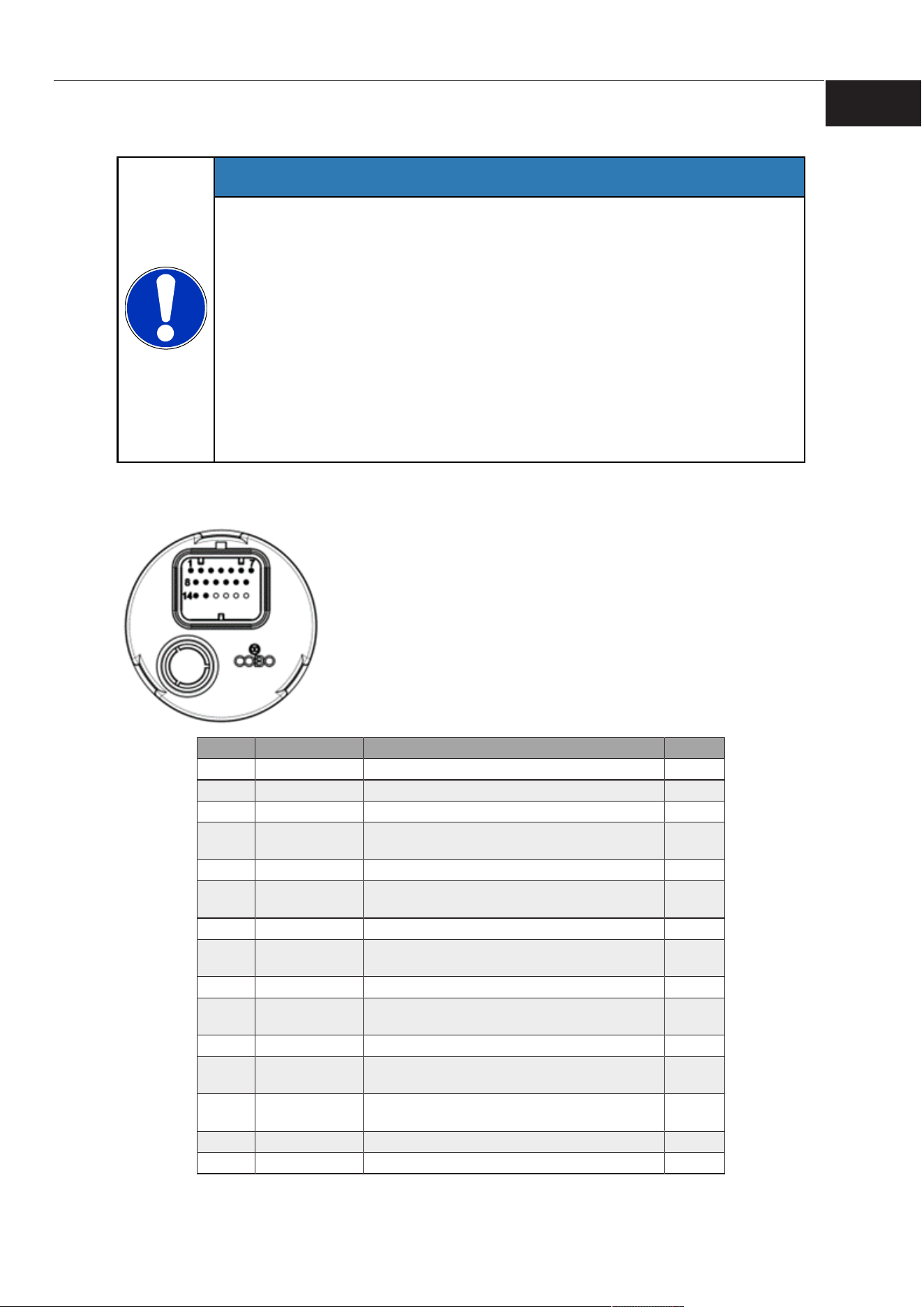
4.3.1 Ecu Keyless
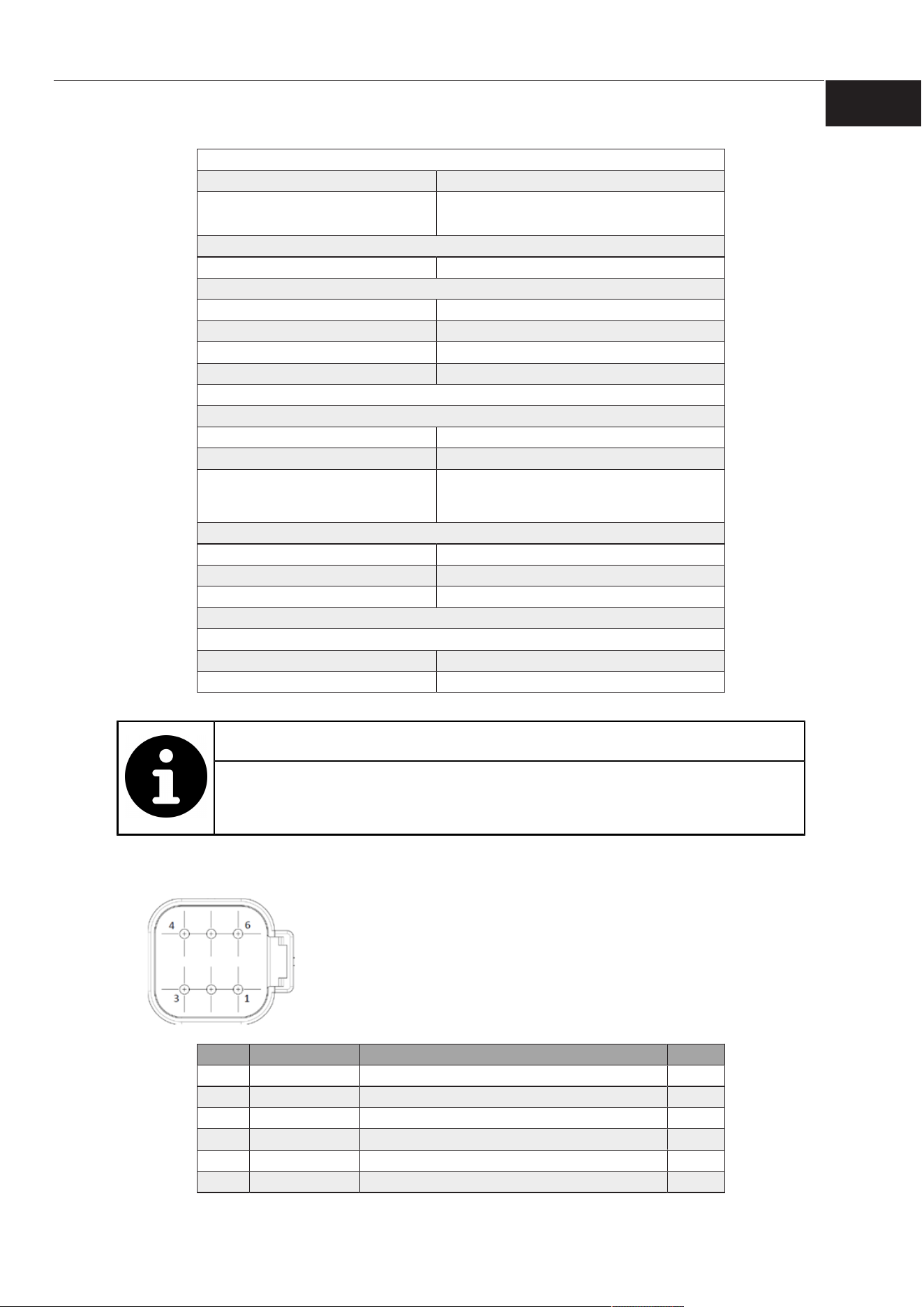
26-pin Superseal connector (5-6447223-0) integrated directly into the
plastic case.
The first 15 pins of the connector are used (see figure).
The counterpart connector to be used is the SuperSeal 26-pin Series
Connector (PN 3-1437290-7), use pins and cross section cable
appropriate to the current applied on it.
Use sealing plug (PN 4-1437284-3) on the non-wired pins to ensure IP
protection of the core unit.
Pin Name Description Type
1 VBAT Positive power supply A
2 GND Negative power supply B
3 IN0 Digital/analogue input 0 F
4 DOH0
High side digital output configurable as Input/
Output 0
C
5 IN1 Digital/analogue input 1 F
6 DOH1
High Side digital output configurable as input/
output 1
C
7 IN2 Digital/analogue input 2 F
8 DOH2
High Side digital output configurable as input/
output 2
C
9 CANH CAN Bus High E
10 DOH3
High Side digital output configurable as input/
output 3
C
11 CANL CAN Bus Low E
12
BUTTON 0Ecu
Keyless [}11]
Button output 0 D
13
BUTTON 1Ecu
Keyless [}11]
Button output 1 D
14 IN3 Digital/analogue input 3 F
15 - - -
KEYLESS-SYSTEM
FEATURES AND FUNCTIONALITIES
ENG
Copyright Cobo Spa. All rights reserved. Contents subject to change without notice. 11
Pin configuration table
Pin type A
Max. input voltage +33.7V
Max. pin current
Continuous use: 5A
Impulsive use: 10A (max 300ms)
Pin type B
Max. pin current 200mA
Pin type C
Operating input voltage range 0V..+32V
Minimum input impedance 60kΩ
Operating output voltage range 0V..+32V
Max. output current 1A
Pin type D
Certified for Functional Safety, PL d, according to ISO 13849-1/-2
Operating voltage range 0V..+VB
Max. current 0.01A
Impedance
View chapter Ecu Keyless electrical
connection with the button [}12] to know
the button internal connection
Pin type E
Physical layer ISO11898 Standard Hi-Speed CAN
Input pin protection ±36V
Transient protection (ESD) ±30kV Human body model (150pF per 330Ω)
Pin type F
Redundant digital/ analogue input
Max. input voltage Nominal voltage: 0V..32V
Minimum impedance 200kΩ
Functional Safety certified.
INFORMATION NOTE
For further information on VT3 Visual Tool software programming
(Software Installation), please refer to the ‘Specific Supplement’ of the
device.
4.3.2 Antenna-ext
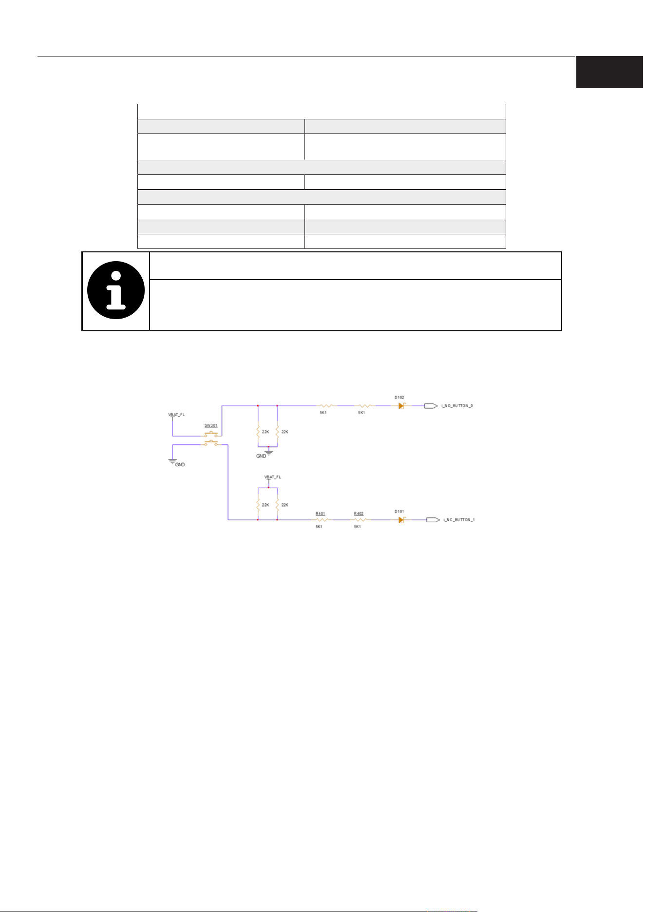
Deutsch 6 pin connector (DT13-6P) integrated directly into the plastic case.
The counterpart connector to be used is the DEUTSCH 6-pin Series
Connector (DT06-6S-C015), use pins and cross section cable appropriate to
the current applied on it.
The use of a sealing plug (4-1437284-3) on the unwired pins ensures the IP
protection of the central unit.
Pin Name Description Type
1 VBAT Positive power supply A
2 GND Negative power supply B
3 - - -
4 - - -
5 CANH CAN-BUS High C
6 CANL CAN-BUS Low C
KEYLESS-SYSTEM
FEATURES AND FUNCTIONALITIES
ENG
Copyright Cobo Spa. All rights reserved. Contents subject to change without notice. 12
Pin configuration table
Pin type A
Max. input voltage +36V
Max. pin current
Continuous use: 2A
Impulsive use: 10A (max 300ms)
Pin type B
Max. pin current 2A
Pin type C
Physical layer ISO11898 Standard Hi-Speed CAN
Input pin protection ±36V
Transient protection (ESD) ±6kV Human body model (100pF per 1.5kΩ)
INFORMATION NOTE
For further information on VT3 Visual Tool software programming
(Software Installation), please refer to the ‘Specific Supplement’ of the
device.
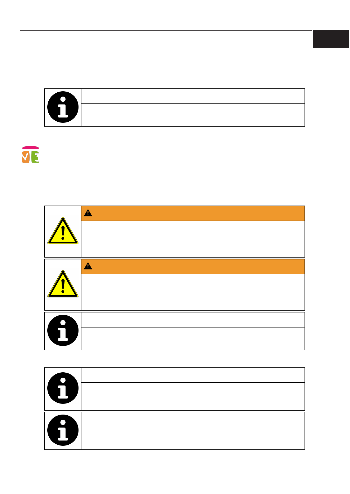
4.4 Ecu Keyless electrical connection with the button
In the following figure it is reported the redundant button schematic to allow a better integration of
the system in the vehicle.
KEYLESS-SYSTEM
SOFTWARE PROGRAMMING AND DEVELOPMENT
ENG
Copyright Cobo Spa. All rights reserved. Contents subject to change without notice. 13
5 SOFTWARE PROGRAMMING AND DEVELOPMENT
The basic system requires software deployment via VT3 Visual Tool to operate.
Parameter customization is performed via CUST.
The required parameters depend on the vehicle type and must be derived from field measurements.
INFORMATION NOTE
For information on system calibration, refer to chapter “Calibration” in
the document “Keyless-System-ENG-QS”.
5.1 VT3 application software development tool
The use of the product is based on programming that must be carried out before the device can be
used.
For this purpose, the product is supplied with the preparation for loading the application software,
which the customer can implement independently via the VT3 Visual Tool programming system,
owned by COBO.
VT3 Visual Tool is a comprehensive suite for programming devices that control mobile vehicles. It
allows the graphics and logic of the device to be programmed via a WYSIWYG graphical interface
that applies the IEC61131 and C standard languages.
WARNING
The customer is responsible for the implementation of its own
software.
1) Carry out approval tests by the competent bodies according to the regulations
in force.
WARNING
Risk of injury and/or material damage due to the development of
functional safety applications with VT3 Visual Tool
VT3 Visual Tool is not suitable for the development of functional safety applications
with this device.
INFORMATION NOTE
To view the Terms of use refer to the EULA, which is accessible from
the VT3 Visual Tool menu.
Documentation
INFORMATION NOTE
For the correct use of the programming system, please refer to the
VT3 Visual Tool manual and its specific supplement, available within
the software under File>vt3 manual.
INFORMATION NOTE
For further information, contact COBO customer service.
KEYLESS-SYSTEM
SOFTWARE PROGRAMMING AND DEVELOPMENT
ENG
Copyright Cobo Spa. All rights reserved. Contents subject to change without notice. 14
INFORMATION NOTE
Programming and/or diagnostic tools can be provided on request.
5.2 CUST programming tool
CUST is a multi-protocol software, developed by COBO, which aims to communicate with ECUs
(Electronic Control Units) and HMIs (Human Machine Interfaces).
The main objective of the CUST project is to offer the user software with a simple graphical
interface that allows communication, interaction and data analysis of all COBO devices on the
vehicle, through the use of a PC and a CAN PC interface.
CUST allows you to:
• Load devices with various COBO protocols and standards
• Diagnose devices with their protocols
• Downloading/uploading parameter files and event logs
• Other Features...
INFORMATION NOTE
For further information, please refer to the “CUST_User_Manual”
available in the COBO public FTP at the following address: CUST
manual
5.2.1 KEYLESS_Calibration
System parameter configuration and calibration by the user is possible via a dedicated CUST
plugin.
INFORMATION NOTE
For more information, see the document “‘COBO-CUST KEYLESS
Plugin User Manual”.
KEYLESS-SYSTEM
INSTALLATION
ENG
Copyright Cobo Spa. All rights reserved. Contents subject to change without notice. 15
6 INSTALLATION
CAUTION
Risk of exceeding FCC/ISED RF exposure limits if the radio devices
are installed too close to the operator.
1) Install the radio devices at least 50 mm away from the operator’s body.
NOTICE
Risk of reduced BLE communication performance due to shielding by
metallic surfaces.
Metallic structures can attenuate or block the BLE signal of the system.
1) Do not install the devices behind or enclosed by metal panels or structures.
NOTICE
Risk of property damage and/or malfunction caused by the falling of the
device
1) Handle the device with care
NOTICE
Risk of material damage due to modification of fixing holes
1) Do not change fixing hole dimensions
NOTICE
Risk of material damage and/or malfunction due to heat sources,
strong vibrations or electromagnetic disturbances
1) Do not mount the device near sources of heat, vibration or electrical/magnetic
disturbances
INFORMATION NOTE
The standard units of measurement in drawings are mm for linear
dimensions and degrees for angles.
6.1 Ecu Keyless Installation
6.1.1 Accessories
Use only the components supplied with the control unit:
• Ecu Keyless
• Gasket
• Nut
• Nut cover
KEYLESS-SYSTEM
INSTALLATION
ENG
Copyright Cobo Spa. All rights reserved. Contents subject to change without notice. 16
6.1.2 Procedure
NOTICE
Risk of device malfunction due to battery disconnection
If the battery is accidentally disconnected, the device is without power.
1) Connect the device directly to the battery.
2) Do not route power through fuses or other devices.
• Identify an ECU installation location inside the cabin that ensures optimal orientation of the BLE
reception lobes toward the cabin entry and the operator approach to the vehicle.
INFORMATION NOTE
For information on ECU antenna radiation lobes, see the chapter “ECU
radiation lobes” in the document “Keyless-System-ENG-QS”.
• The dashboard must meet the following requirements:
– Thickness between 1.5mm and 4mm.
– The panel must have a flatness of 0.4mm in the mounting area to allow for an optimal seal.
– The two parts of the plane (top and bottom) must have a parallelism of 0.2mm between
them. Panels with different characteristics do not allow sealing.
– Prefer a plastic panel for maximum system functionality. Avoid mounting the device in a
metal box or similar.
• Provide the application hole pattern shown in
the figure.

KEYLESS-SYSTEM
INSTALLATION
ENG
Copyright Cobo Spa. All rights reserved. Contents subject to change without notice. 17
3. Insert the gasket on top of the Ecu Keyless.
4. Insert Ecu Keyless+gasket into the panel. The gasket must remain on the inside part of the
panel.
5. Screw the nut with 5Nm torque.
6. Push the nut cover onto the nut, paying attention to position it with the ribs along the straight
side of the nut.
KEYLESS-SYSTEM
INSTALLATION
ENG
Copyright Cobo Spa. All rights reserved. Contents subject to change without notice. 18
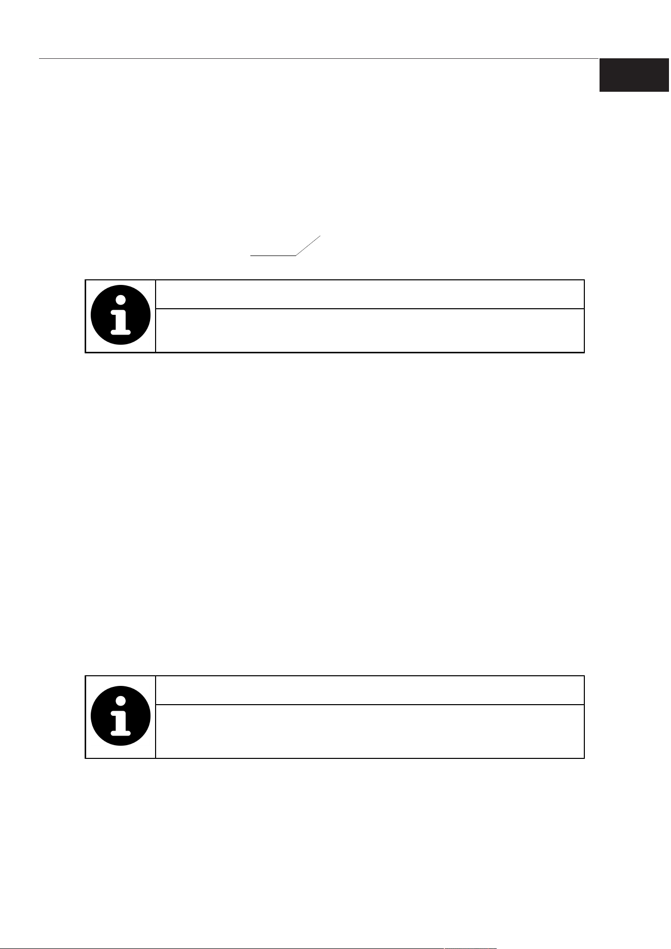
7. Connect the wiring harness to the device connector.
Connector
8. Start system configuration on the machine.
INFORMATION NOTE
System configuration depends on the specific installation on the
vehicle. View Software programming and development [
}
13].
6.2 Antenna-ext installation
6.2.1 Accessories
Use only the components supplied with the antenna:
• Antenna
• Gasket
Provide screws with these characteristics:
• n.4 M4
• Sufficient length considering the thickness of the mounting panel and 9mm length of the
threaded insert
6.2.2 Procedure
• A model/characterisation on where to mount the device will be available. Contact COBO
salesmen for further information.
• To determine the number of devices and the position on the vehicle contact COBO.
• Identify external antenna installation locations that maximize the system BLE signal coverage.
– Prefer elevated mounting positions.
– Orient the antenna to exploit the Y and Z radiation lobes for improved coverage.
INFORMATION NOTE
For information on external antenna radiation lobes, see the chapter
“External Antenna Radiation Lobes” in the document “Keyless-
System-ENG-QS”.
• If door unlocking is controlled by the Keyless-System, identify an external antenna installation
position near the door or in a user-accessible area to allow NFC unlocking with the Keyfob.
• The panel must have a flatness of 0.4mm and maximum roughness of Ra3.2 in the mounting
area to allow for an optimal seal.

KEYLESS-SYSTEM
INSTALLATION
ENG
Copyright Cobo Spa. All rights reserved. Contents subject to change without notice. 19
• Provide the application hole pattern
shown in the figure.
1. Insert gasket into the appropriate location.
2. Connect the polarised wiring to the connector shown in the figure.
3. Place the antenna on the surface.
4. Insert the 4 screws from below into the holes shown in the figure.
1
2
1 M4 threaded inserts 9 mm deep 2 Connector
5. Torque the screws (tightening torque: 4Nm).
6. Start system configuration on the machine.
KEYLESS-SYSTEM
TECHNICAL DATA
ENG
Copyright Cobo Spa. All rights reserved. Contents subject to change without notice. 20
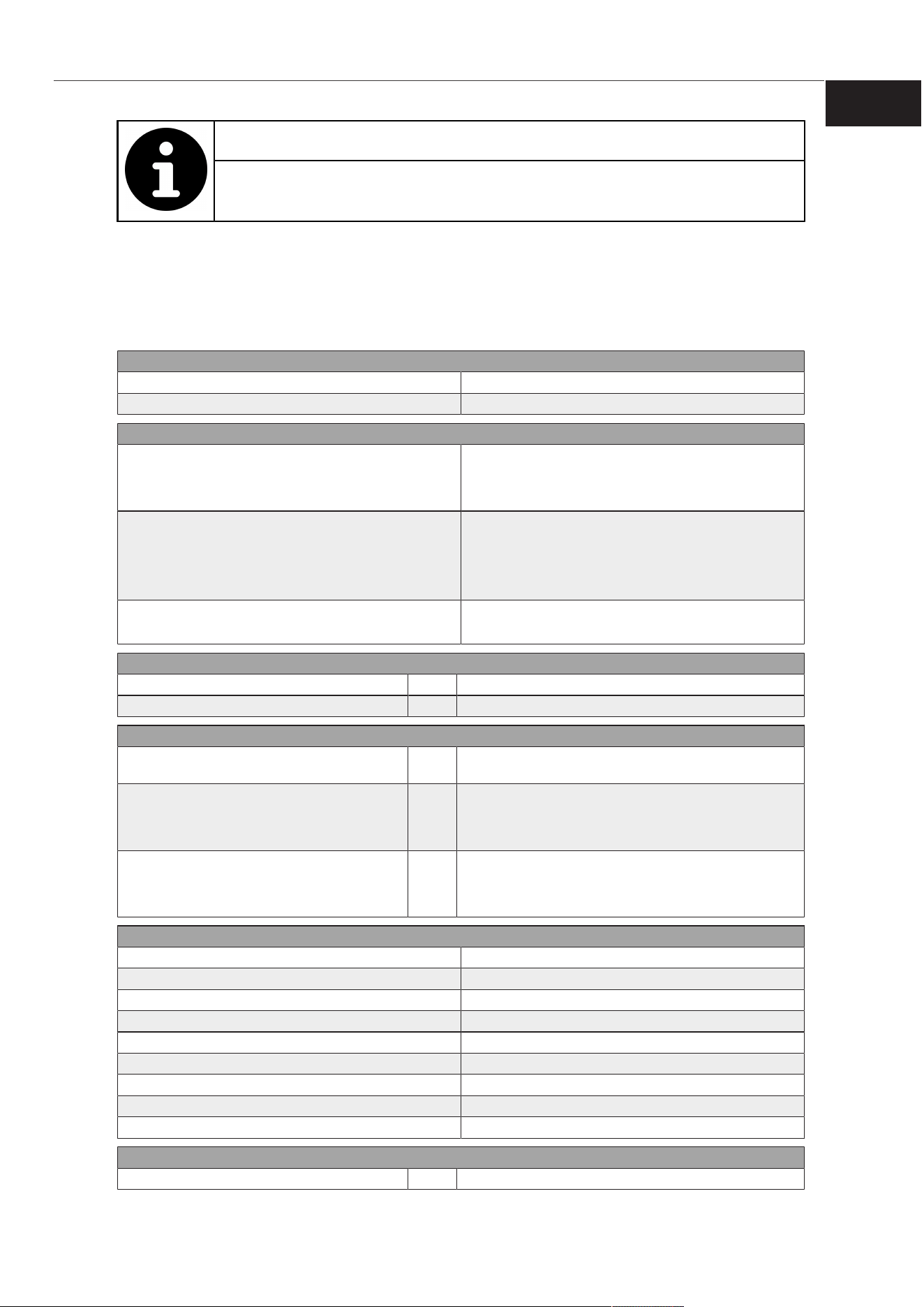
INFORMATION NOTE
System configuration depends on the specific installation on the
vehicle. View Software programming and development [
}
13].
7 TECHNICAL DATA
7.1 Ecu Keyless
Control system
Microprocessor Arm 32-bit Cortex-M33
Space for the available for the VT3 Software 192kB
Electrical characteristics
Power supply voltage range
Operating: +6..+32VDC
Cold Cranking 4.5VDC
Device must be connected to power supply
Power supply current
Run Mode: <200mA @12V
Sleep Mode: <5mA, @12V all wake-up sources active
Run Mode: <200mA @24V
Sleep Mode: <5mA, @24V all wake-up sources active
Total power output current max
1A on each DOH pin
4A on the total of the 4 DOH pins
Inputs and outputs
Digital high side outputs n. 4 Configurable as analogue/digital inputs 0V..32V
Digital/Analogue redundant inputs n. 4 0V..+32V
Interfaces
CAN-BUS line n. 1
2.0B high speed, (11 or 29 bit identifier), ISO 11898-2
compliant
Bluetooth n. 1
Version: 5.2
Frequency: 2400..2483MHz
Maximum Power Output: 8dBm
NFC n. 1
Type: NFC-V, ISO15693 compliant
Frequency: 13.56MHz
Magnetic field strength (H) <0.73A/m @ 10m
Mechanical and environmental characteristics
Dimensions (DxH) 57x75mm (without connector)
Push button life 200000 Cycles
Clamping system Plastic nut, M25
Panel sealing system Gasket
Operating temperature -40°C..+80°C, compliant to ISO IEC60068
Storage temperature -40°C..+85°C, compliant to ISO IEC60068
Ecu Keyless protection grade IP66, IP67, compliant to IEC 60529
Protection grade expected with proper installation IP66, compliant to IEC 60529
Weight 97g
Other features
Max number of associable keys n. 16

KEYLESS-SYSTEM
TECHNICAL DATA
ENG
Copyright Cobo Spa. All rights reserved. Contents subject to change without notice. 21
Other features
Max number of associable antennas n. 4
7
Start/stop button n. 1
Backlight button, configurable color via software
Button stroke: 1.5mm
Button activation force: 10.5N
Maximum BLE signal reception distance
15m in passive mode in open field
15m in active mode in open field
NFC signal reception distance with Wallet 3cm
NFC signal reception distance with Keyfob 1cm
Digital/Analogue inputs Configurable as wake up sources
Information about materials
Case material PA6 30%GF, POM, ABS
Sealing material EPDM
7.2 Keyfob
Control system
Microprocessor Cortex M0
Electrical characteristics
Battery Replaceable battery CR2430, +3.3VDC
Interfaces
Bluetooth n. 1
Version: 5.2
Frequency: 2400..2483MHz
Maximum Power Output: 8dBm
NFC n. 1
Type: NFC-V, ISO15693
Frequency: 13.56MHz
Mechanical and environmental characteristics
Dimensions (WxHxD) 79x43x17.5mm
Operating temperature -20°C..+60°C, ISO IEC60068 compliant
Storage temperature
-30°C..+70°C (without battery), ISO IEC60068
compliant
KEYFOB Protection grade IP64, IP67, compliant to IEC 60529
Weight 38g
Other features
Max number of associable ECUs n. 12
Buttons n. 3
Customizable ideogram
Stroke for activation: 0.33mm
Maximum stroke: 0.5mm
Activation trigger force: 3.8N
Push button life: 100000 cycles
Battery state
Viewed on display (only possible if configured by the
customer via software)
Information about materials
Key holder material ZAMAK
Body material ABS
7
The multiple association of keyfobs, if 4 antennas are installed on the vehicle, may cause a
pairing delay.

KEYLESS-SYSTEM
TECHNICAL DATA
ENG
Copyright Cobo Spa. All rights reserved. Contents subject to change without notice. 22
7.3 Wallet
Electrical characteristics
Power supply Passive
Interfaces
NFC n. 1 NFC-V, 13.56MHz, ISO15693
Mechanical and environmental characteristics
Dimensions (WxHxD) 50x46x9.7mm
Operating temperature -40°C..+80°C, ISO IEC60068 compliant
Storage temperature -40°C..+85°C, ISO IEC60068 compliant
Protection grade IP64, IP67, compliant to IEC 60529
Weight 13g
Information about materials
Body material ABS
7.4 Antenna-ext
Control system
Microprocessor Arm 32-bit Cortex-M33
Electrical characteristics
Power supply voltage range
Operating +6..+32VDC
Cold Cranking 4.5VDC
Device must be connected to power supply
Power supply current
Run Mode: <50mA @12V (no NFC)
Sleep Mode: <5mA, @12 V
Run Mode: <50mA @24V
Sleep Mode: <5mA, @24V
Interfaces
CAN-BUS line n. 1
2.0B high speed, (11 or 29 bit identifier), ISO 11898-2
compliant
Bluetooth n. 1
Version: 5.2
Frequency: 2400..2483MHz
Maximum Power Output: 8dBm
NFC n. 1
Type: NFC-V, ISO15693 compliant
Frequency: 13.56MHz
Magnetic field strength (H) <0.73A/m @ 10m
Mechanical and Environmental characteristics
Dimensions (WxHxD) 70x70.5x30mm
Panel sealing system Gasket
Operating temperature -40°C..+85°C, compliant to ISO IEC60068
Storage temperature -40°C..+85°C, compliant to ISO IEC60068
Antenna protection grade IP66, IP67, IP69K, compliant to ISO 60529
Protection grade expected with proper installation IP66, compliant to ISO 60529
Weight 85.6g
Other features
Maximum BLE signal reception distance
15m in passive mode in open field
15m in active mode in open field
NFC signal reception distance with Wallet 3cm
KEYLESS-SYSTEM
BATTERY REPLACEMENT
ENG
Copyright Cobo Spa. All rights reserved. Contents subject to change without notice. 23
Other features
NFC signal reception distance with Keyfob 1cm
Information about materials
Body material ABS
Sealing material EPDM
8 BATTERY REPLACEMENT
INFORMATION NOTE
The system reads and monitors the battery status.
Low battery warning must be implemented using the VT3 Visual Tool.
8.1 Accessories
The product is equipped with a battery: In case of low battery, buy a new battery (CR2430).
8.2 Procedure
1. Remove the battery cover by pressing into the slot with a slotted screwdriver (0.4x2.4mm tip),
without removing the red gasket
2. Lift the battery cover
3. Replace the CR2430 battery, taking care not to remove the red gasket
4. Relocate the battery cover
9 KEYFOB RECOGNITION WITH LOW BATTERY
If the Keyless Keyfob battery is depleted, BLE identification is not possible and related functions
(e.g., vehicle unlock and start) cannot be authorized.
NOTICE
Risk of system malfunction if NFC is not enabled via the VT3 Visual
Tool library function
1) Implement NFC management function in the application software using the
specific VT3 Visual Tool library function vt3_customer_app
INFORMATION NOTE
For further information, see the relevant chapter in the “Library”
section in the document “Keyless-system specific supplement”
KEYLESS-SYSTEM
KEYFOB RECOGNITION WITH LOW BATTERY
ENG
Copyright Cobo Spa. All rights reserved. Contents subject to change without notice. 24
Keyfob recognition via external antenna (for vehicle access — if supported)
INFORMATION NOTE
Follow this procedure only if vehicle door unlocking is controlled by
the Keyless system (function implemented via VT3 visual tool).
1. Place the button side of the Keyfob associated with the vehicle close to the top side of the
external antenna
2. Wait 2s seconds. The external antenna detects the Keyfob via NFC and sends a CAN message
to the ECU. The ECU forwards the event to the application, where the related actions (e.g., door
unlock) can be implemented using the VT3 Visual Tool..
If the key is not detected, remove the key and repeat the operation.
Keyfob recognition via ECU for vehicle start up
INFORMATION NOTE
Follow this procedure only if vehicle start is controlled by the Keyless
system (function implemented via VT3 Visual Tool).
3. Place the button side of the Keyfob associated with the vehicle close to the ECU pushbutton.
4. Wait 2s seconds. The ECU detects the Keyfob via NFC and forwards the event to the
application, where the related actions (e.g., vehicle start up) can be implemented using the VT3
Visual Tool.
If the key is not detected, remove the key and repeat the operation.
5. Start the vehicle within xx seconds before the ECU loses the association.
The association time depends on a timer that must be implemented using the VT3 Visual Tool.

KEYLESS-SYSTEM
MAINTENANCE AND DISPOSAL
ENG
Copyright Cobo Spa. All rights reserved. Contents subject to change without notice. 25
10 MAINTENANCE AND DISPOSAL
10.1 Maintenance
This device is maintenance-free.
10.2 Repairing
In the event of a malfunction, take the reference contacts indicated in the supply contract and
activate the complaints handling procedure by sending an e-mail.
10.3 Disposal
Dispose of the device in accordance with current regulations: The device must not be disposed of in
the municipal waste collection, but must be handled as special waste.
COBO spa actively manages/transmits the information required for end-of-life management and
assesses the compliance of its products in relation to the requirements of:
• Regulation (EC) No 1907/2006 REACH and SCIP notification required by the Directive 2008/98/
EC “Waste Framework Directive”, Article 9(1)(i), as amended by Dir. 2018/851/EU
• Regulation (EU) 2019/1021 (POPs)
• Directive 2000/53/EC (ELV), where applicable
• Regulation (EU) 2023/1542 and, until its complete repeal, Directive 2006/66/EC (for the parts
not conflicting with the Regulation), where applicable
This product contains one or more batteries, which must be handled according to Regulation (EU)
2023/1542 and, until its complete abrogation, according to Directive 2006/66/EC, for those parts not
conflicting with the Regulation.
10.4 Product Environmental Compliance
COBO Spa is committed to ensuring the compliance of its products with mandatory regulations, with
particular reference to European ones.
To this end, COBO Spa does not systematically perform chemical analyses on its products, but
requires evidence of conformity from all suppliers and undertakes to assess their reliability and
correctness to the best of its knowledge.
For more information, contact [email protected] .

C.O.B.O. SpA
Via Tito Speri 10,
Leno, 25024 (BS)
Tel: +39 030 90451
Fax: +39 030 9045330
www.cobogroup.net