Visit our website at: https://www.harborfreight.com
email our technical support at: [email protected]
58021
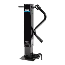
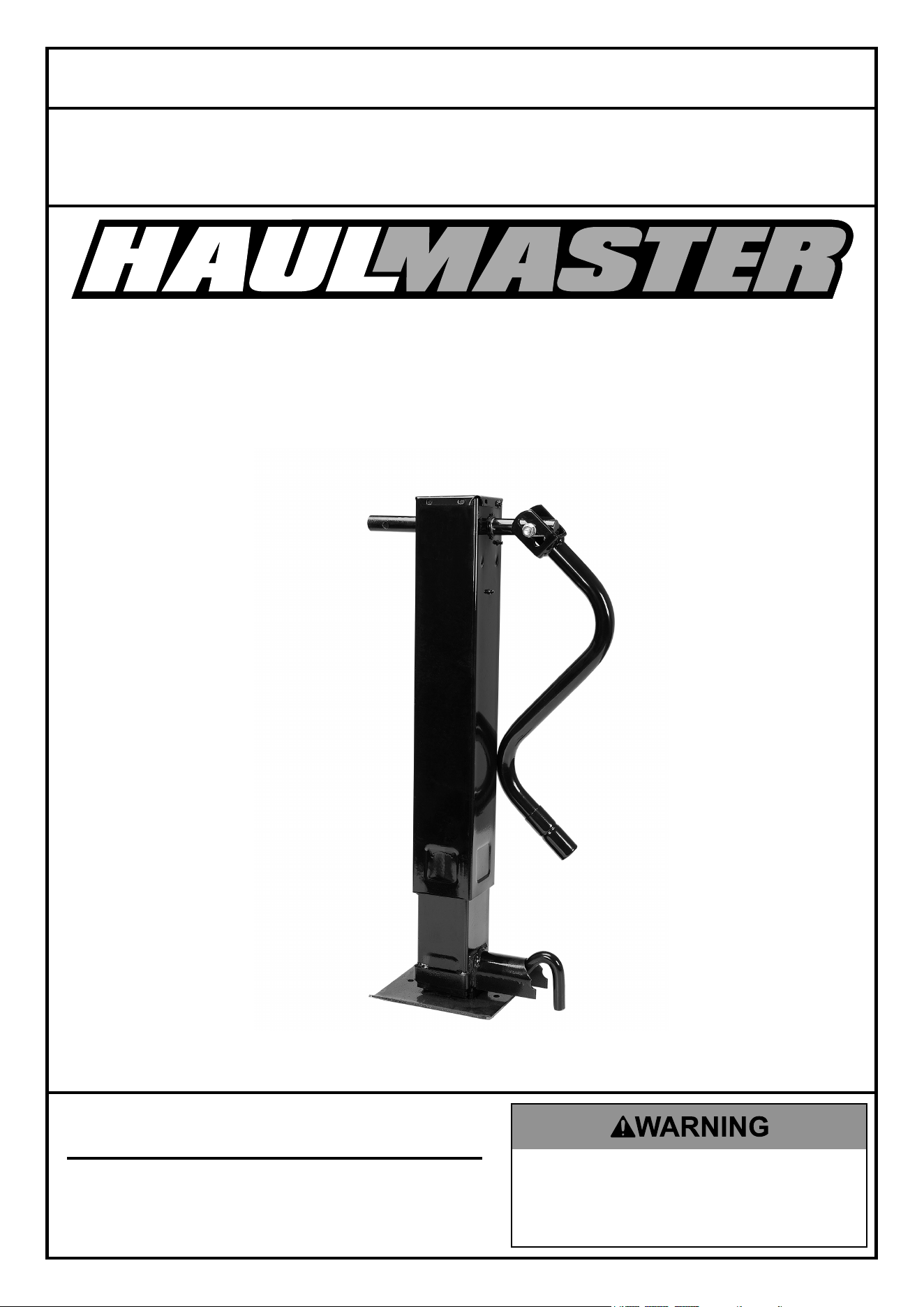
COMMERCIAL DUTY
DROP-LEG
TRAILER JACK
®
Owner’s Manual & Safety Instructions
Save This Manual Keep this manual for the safety warnings and precautions, assembly,
operating, inspection, maintenance and cleaning procedures. Write the product’s serial number in the
back of the manual near the assembly diagram (or month and year of purchase if product has no number).
Keep this manual and the receipt in a safe and dry place for future reference. 25b
When unpacking, make sure that the product is intact
and undamaged. If any parts are missing or broken,
please call 1-800-444-3353 as soon as possible.
Copyright
©
2025 by Harbor Freight Tools
®
. All rights reserved.
No portion of this manual or any artwork contained herein may be reproduced in
any shape or form without the express written consent of Harbor Freight Tools.
Diagrams within this manual may not be drawn proportionally. Due to continuing
improvements, actual product may differ slightly from the product described herein.
Tools required for assembly and service may not be included.
Read this material before using this product.
Failure to do so can result in serious injury.
SAVE THIS MANUAL.
Page 2 For technical questions, please call 1-800-444-3353. Item 58021
SaFety OperatiOn MaintenanceinStallatiOn
table of contents
Safety ......................................................... 3
Specifications ............................................. 4
Installation .................................................. 5
Operation .................................................... 6
Maintenance ............................................... 8
Parts List and Diagram .............................. 10
Warranty .................................................... 12
®
WarninG SyMBOlS anD DeFinitiOnS
This is the safety alert symbol. It is used to alert you to potential
personal injury hazards. Obey all safety messages that
follow this symbol to avoid possible injury or death.
Indicates a hazardous situation which, if not avoided,
will result in death or serious injury.
Indicates a hazardous situation which, if not avoided,
could result in death or serious injury.
Indicates a hazardous situation which, if not avoided,
could result in minor or moderate injury.
Addresses practices not related to personal injury.
Page 3For technical questions, please call 1-800-444-3353.Item 58021
SaFetyOperatiOnMaintenance inStallatiOn
iMpOrtant SaFety inFOrMatiOn
read all safety warnings and instructions. Failure to follow the warnings and instructions
may result in serious injury. Save all warnings and instructions for future reference.
Basic Safety information
Keep work area clean and well lit. Cluttered or dark areas invite accidents.
personal safety
1. Stay alert, watch what you are doing and
use common sense when operating a tool.
Do not use a tool while you are tired or under
the influence of drugs, alcohol or medication.
A moment of inattention while operating tools
may result in serious personal injury.
2. Use personal protective equipment.
always wear eye protection. Safety equipment
such as non-skid safety shoes or a hard hat used for
appropriate conditions will reduce personal injuries.
Service
Have your tool serviced by a qualified repair person using only identical replacement parts.
This will ensure that the safety of the tool is maintained.
Specific Safety Warnings
1. All welding must be performed by an AWS
certified welder to meet all applicable safety
regulations by DOT, NHTSA, and all other
governmental and standards agencies.
2. Do not exceed rated capacity.
3. Use on flat, level, hard surface
capable of supporting load.
4. Wear ANSI-approved safety goggles during use.
5. Prevent trailer wheels from moving using
wheel chocks while raising or lowering.
6. Before towing, fully raise Trailer Jack.
7. Keep out from under jack and tongue when applying
and releasing load or when jack is supporting load.
8. Inspect before use. Do not use if
parts are loose or damaged.
9. Mount and use in accordance with the Department
of Transportation (DOT) regulations.
10. Maintain labels and nameplates on the tool.
These carry important safety information.
If unreadable or missing, contact
Harbor Freight Tools for a replacement.
11. Apply force to jack vertically only.
Side forces will compromise the jack.
12. Do not use blocks for additional ground clearance.
13. Do not climb aboard any vehicle supported by jack.
14. This product is not a toy. Keep it
out of reach of children.
15. Follow all state regulations for towing when
using Trailer Jack, including using safety
chains securely attached to the towing vehicle
when the trailer is hooked to the vehicle.
16. Check ground clearance carefully after installing.
Do not use on any road or driveway that requires
more ground clearance than this jack provides.
17. Do not use for aircraft purposes.
18. The warnings, precautions, and instructions
discussed in this instruction manual cannot
cover all possible conditions and situations
that may occur. It must be understood by the
operator that common sense and caution are
factors which cannot be built into this product,
but must be supplied by the operator.
SaVe tHeSe inStrUctiOnS.
Page 4 For technical questions, please call 1-800-444-3353. Item 58021
SaFety OperatiOn MaintenanceinStallatiOn
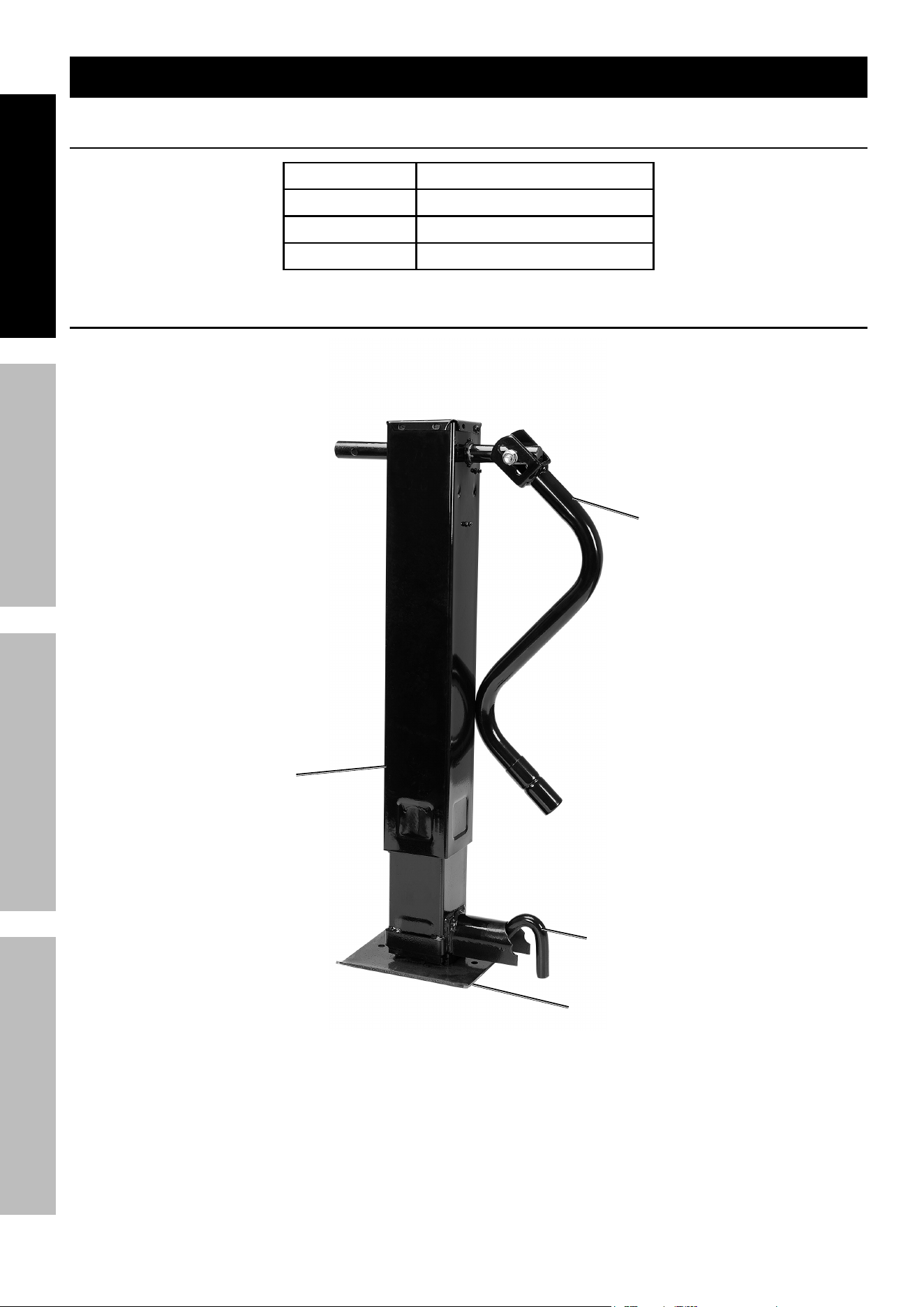
Functional Description
Specifications
Weight Capacity 10,000 lb.
Travel Length 13-3/8″
Lift Range 27-3/8″ – 54-1/4″
Total Lift 26-7/8″ travel length + drop leg
components
Drop leg
locking pin
Hand crank
Outer tube
Page 5For technical questions, please call 1-800-444-3353.Item 58021
SaFetyOperatiOnMaintenance inStallatiOn
installation instructions
read the entire iMpOrtant SaFety inFOrMatiOn section at the beginning of this
manual including all text under subheadings therein before set up or use of this product.
Mounting
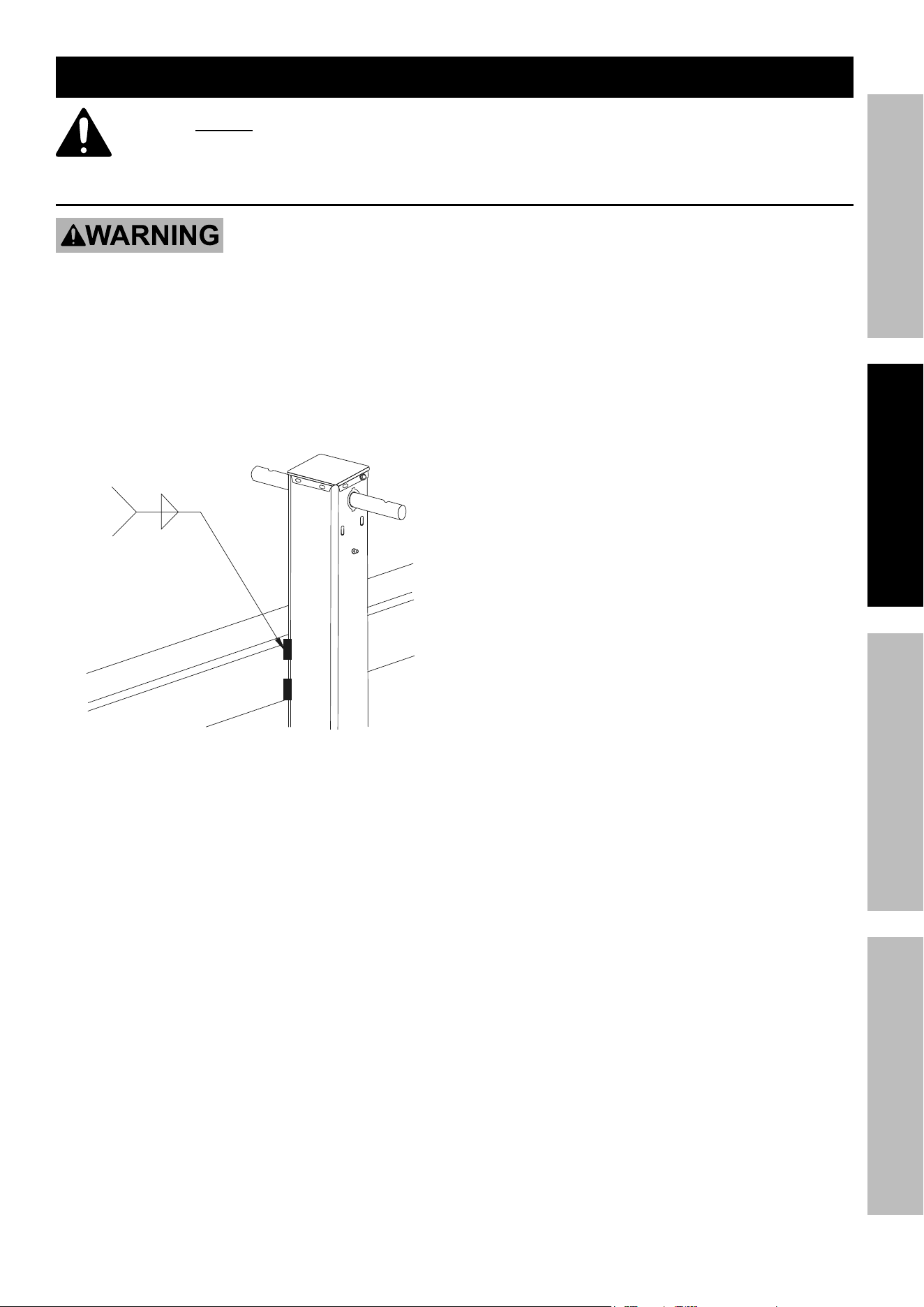
tO preVent SeriOUS inJUry anD DeatH FrOM trailer JacK DetacHMent Or FailUre:
all welding must be performed by an aWS certified welder to meet all applicable safety
regulations by DOt, nHtSa, and all other governmental and standards agencies.
1. All welding surfaces must be prepared and cleaned
thoroughly to allow a proper weld to be created.
2. Clamp the Outer Tube to the Trailer in the needed
location and weld in 4 locations total, 2x 3″ welds
on each side as shown. Use 1/4″ fillet welds.
2x
.25
.25
3
3
3. After welding, welds must be properly
cleaned and painted or otherwise protected
from corrosion and deterioration.

Page 6 For technical questions, please call 1-800-444-3353. Item 58021
SaFety OperatiOn MaintenanceinStallatiOn
Operation instructions
read the entire iMpOrtant SaFety inFOrMatiOn section at the beginning of this
manual including all text under subheadings therein before set up or use of this product.
Spring-loaded Drop leg
tO preVent SeriOUS inJUry:
Make sure locking pin inserts fully in engage position with no gap between the locking pin and
housing before applying load; do not use if pin does not engage and insert fully.
Do not adjust locking pin under load.
Spring-loaded drop leg retracts forcefully. carefully control drop leg before adjusting locking pin.
1. The Drop Leg on this Trailer Jack is spring-loaded,
and the Locking Pin has three positions:
Disengaged (Horizontal, partially pulled out),
Engaged (Vertical, not completely inserted),
Engaged and Locked (Vertical, completely inserted)
2. Disengaged: (Horizontal, partially pulled out)
a. This position releases the Spring mechanism,
allowing the Drop Leg to fall freely.
b. Keep clear from under the Drop Leg and carefully
control it before adjusting the Locking Pin.
c. Turn the Locking Pin clockwise until
it is horizontal to disengage it.
3. engaged: (Vertical, not completely inserted)
a. This position engages the Spring mechanism,
causing the Drop Leg to retract forcefully.
b. Keep clear from above the Drop Leg and carefully
control it before adjusting the Locking Pin.
c. Turn the Locking Pin to align it
vertically to engage the spring.
4. engaged and locked:
(Vertical, completely inserted)
a. This position inserts the Locking Pin into an
adjustment hole, locking the Drop Leg in place.
b. WarninG! tO preVent SeriOUS inJUry:
this is the only acceptable position
the locking pin can be in before a load
can be applied to the trailer Jack.
c. Turn the Locking Pin to align it vertically and
adjust the Drop Leg until the Locking Pin
inserts completely into an adjustment hole.
The top portion of the pin should press
against the housing with no gap.

Page 7For technical questions, please call 1-800-444-3353.Item 58021
SaFetyOperatiOnMaintenance inStallatiOn
Mounting the trailer to the towing Vehicle
1. Before mounting, chock the trailer wheels
to prevent the trailer from rolling.
2. Rotate the Crank to raise the trailer to the
level of the towing vehicle’s hitch.
3. If needed, the Locking Pin can be temporarily pulled
out to allow the Drop Leg to be adjusted.
WarninG! tO preVent SeriOUS inJUry:
Do not overextend the Drop leg.
Make sure to secure the Locking Pin
back in place after adjustment. For the
5,000 lb. Trailer Jack, make sure that the
spring locks the Locking Pin in place.
4. With the assistance of a spotter,
back the vehicle to the trailer.
5. Mount the trailer onto the towing vehicle’s hitch.
6. Turn the Crank to retract the Jack slightly,
lowering the trailer and transferring its
weight onto the towing vehicle.
7. Once trailer is fully engaged, continue to
retract Jack up to the “STOP” label on the
Inner Tube. Trailer Jack must always be
fully retracted when towing the trailer.
8. Attach an appropriate safety chain (sold separately).
Dismounting the trailer from the towing Vehicle
1. Before dismounting, chock the trailer wheels
to prevent the trailer from rolling.
2. Rotate the Crank to extend the
Jack and raise the trailer.
3. Continue to extend just enough for the Trailer
Jack to take the weight of the trailer. This will
make it easier to disengage the trailer hitch.
4. Disengage the trailer hitch, any safety
chains or other connections, between
the vehicle and the trailer.
5. You may need to extend the Jack further
to clear the trailer hitch. When the vehicle
is completely clear, and it is safe to do so,
drive the vehicle away from the trailer.
caUtiOn: Have a spotter watch this operation
to be sure the trailer is clear of the vehicle.

Page 8 For technical questions, please call 1-800-444-3353. Item 58021
SaFety OperatiOn MaintenanceinStallatiOn
inspection, testing, and Maintenance
procedures not specifically explained in this manual must
be performed only by a qualified technician.
tO preVent SeriOUS inJUry:
remove load from tailer Jack, park towing vehicle and trailer on flat, level surface, and
chock tires before performing any inspection, maintenance, or cleaning procedures.
tO preVent SeriOUS inJUry FrOM tOOl FailUre:
Do not use damaged equipment. if abnormal noise or vibration occurs,
have the problem corrected before further use.
cleaning, Maintenance, and lubrication
1. BeFOre eacH USe, inspect the general
condition of the tool. Check for:
• loose hardware,
• misalignment or binding of moving parts,
• cracked or broken parts, and
• any other condition that may
affect its safe operation.
2. aFter USe, wipe external surfaces
of the tool with clean cloth.
3. At least annually, apply a small amount of
automotive grease (not included) to the internal
gearing after removing the Cover. Rotate the
Hand Crank to distribute the grease evenly.
4. A lightweight oil must be applied periodically
at both sides of the Trailer Jack where
the Hand Crank enters and exits it.
record Serial number Here:
note: If product has no serial number, record month and year of purchase instead.
note: Some parts are listed and shown for illustration purposes only, and are not available
individually as replacement parts. Specify UPC number when ordering:193175561466.

Page 9For technical questions, please call 1-800-444-3353.Item 58021
SaFetyOperatiOnMaintenance inStallatiOn
pleaSe reaD tHe FOllOWinG careFUlly
THE MANUFACTURER AND/OR DISTRIBUTOR HAS PROVIDED THE PARTS LIST AND ASSEMBLY DIAGRAM
IN THIS MANUAL AS A REFERENCE TOOL ONLY. NEITHER THE MANUFACTURER OR DISTRIBUTOR
MAKES ANY REPRESENTATION OR WARRANTY OF ANY KIND TO THE BUYER THAT HE OR SHE IS
QUALIFIED TO MAKE ANY REPAIRS TO THE PRODUCT, OR THAT HE OR SHE IS QUALIFIED TO REPLACE
ANY PARTS OF THE PRODUCT. IN FACT, THE MANUFACTURER AND/OR DISTRIBUTOR EXPRESSLY
STATES THAT ALL REPAIRS AND PARTS REPLACEMENTS SHOULD BE UNDERTAKEN BY CERTIFIED AND
LICENSED TECHNICIANS, AND NOT BY THE BUYER. THE BUYER ASSUMES ALL RISK AND LIABILITY
ARISING OUT OF HIS OR HER REPAIRS TO THE ORIGINAL PRODUCT OR REPLACEMENT PARTS
THERETO, OR ARISING OUT OF HIS OR HER INSTALLATION OF REPLACEMENT PARTS THERETO.
Page 10 For technical questions, please call 1-800-444-3353. Item 58021
SaFety OperatiOn MaintenanceinStallatiOn
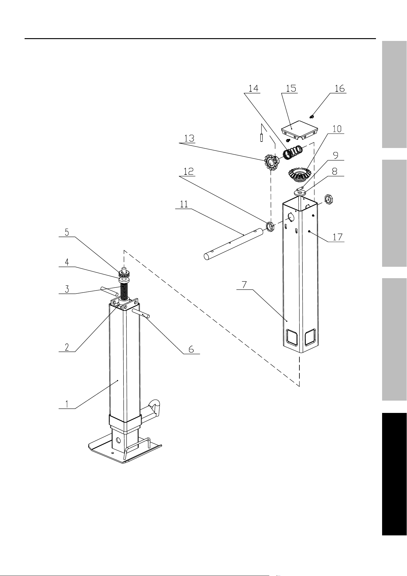
parts list and Diagram
parts list
part Description Qty
1 Asm. Inner Tube 1
2 Nut 1
3 Screw 1
4 Support Washer 1
5 Thrust Bearing 1
6 Pin 2
7 Outer Tube Assembly 1
8 Wear Plate 1
9 Straight Pin 2
10 Bevel Gear 1
11 Cross Shaft 1
12 Bushing 2
13 Bevel Pinion Gear 1
14 Spring 1
15 Cover 1
16 Screw 2
17 Fitting, Grease 2
Page 11For technical questions, please call 1-800-444-3353.Item 58021
SaFetyOperatiOnMaintenance inStallatiOn
assembly Diagram
58021

®
26677 agoura road • calabasas, ca 91302 • 1-800-444-3353
limited 90 Day Warranty
Harbor Freight Tools Co. makes every effort to assure that its products meet high quality and durability standards,
and warrants to the original purchaser that this product is free from defects in materials and workmanship for the
period of 90 days from the date of purchase. This warranty does not apply to damage due directly or indirectly,
to misuse, abuse, negligence or accidents, repairs or alterations outside our facilities, criminal activity, improper
installation, normal wear and tear, or to lack of maintenance. We shall in no event be liable for death, injuries
to persons or property, or for incidental, contingent, special or consequential damages arising from the use of
our product. Some states do not allow the exclusion or limitation of incidental or consequential damages, so the
above limitation of exclusion may not apply to you. THIS WARRANTY IS EXPRESSLY IN LIEU OF ALL OTHER
WARRANTIES, EXPRESS OR IMPLIED, INCLUDING THE WARRANTIES OF MERCHANTABILITY AND FITNESS.
To take advantage of this warranty, the product or part must be returned to us with transportation charges prepaid.
Proof of purchase date and an explanation of the complaint must accompany the merchandise. If our
inspection verifies the defect, we will either repair or replace the product at our election or we may elect to
refund the purchase price if we cannot readily and quickly provide you with a replacement. We will return
repaired products at our expense, but if we determine there is no defect, or that the defect resulted from
causes not within the scope of our warranty, then you must bear the cost of returning the product.
This warranty gives you specific legal rights and you may also have other rights which vary from state to state.