

Version 0
Southwest Microwave, Inc.
Security Systems Division
INTREPID™
Model MS30-POE-S
A SHORT-RANGE OUTDOOR DIGITAL
MICROWAVE TRANSCEIVER
Model MS30-POE-S Installation
and Operation Manual

Model MS30-POE-S Manual
2 Version 0
Trademark Notice and Certifications
INTREPID™, MicroPoint™ and MicroTrack™ are registered trademarks of Southwest Microwave, Inc.
Copyright 1995 and 2026 Southwest Microwave, Inc. All rights Reserved.
FCC Notice
Model MS30-POE-S is classified as a field disturbance sensor. FCC Identifier: CA6MS30.
This device complies with FCC Rules Part 15.249. Operation is subject to the following two conditions:
This device may not cause harmful interference, and this device must accept interference received, including
interference that may cause undesired operation.
Notice: changes or modifications not expressly approved by Southwest Microwave Inc. could void the user’s
authority to operate the equipment.
This equipment has been tested and found to comply with the limits for a Class A digital device, pursuant to
part 15 of the FCC Rules. These limits are designed to provide reasonable protection against harmful
interference when the equipment is operated in a commercial environment. This equipment generates, uses,
and can radiate radio frequency energy and, if not installed and used in accordance with the instruction
manual, may cause harmful interference to radio communications. Operation of this equipment in a residential
area is likely to cause harmful interference in which case the user will be required to correct the interference
at his own expense. This equipment is not suitable for use in locations where children are likely to be present.
CE Compliant: EN 300 440
RoHS Compliant
Radiation Safety
The allowable standard minimum of safe radiation exposure level in the United States as established by the
American National Standards Institute is 5mW/cm
2
. The average Southwest Microwave sensor surface
radiation level (when in operation) is approximately.0186mW/cm
2
or 1/50 of the standard. This level rapidly
dissipates at distances from the unit. For example, at one meter, the figure reduces to .0012mW/cm
2
or 1/800
of the standard.
Copyright Southwest Microwave, Inc. April 2026
6647778-A01
Southwest Microwave, Inc.
9055 South McKemy Street
Tempe, Arizona 85284-2946
Tel: (480) 783-0201
Fax: (480) 783-0401
Email: infossd@southwestmicrowave.com
Web: www.southwestmicrowave.com

Model MS30-POE-S Manual
3 Version 0
INTREPID™ Model MS30-POE-S Software
Southwest Microwave, Inc. thank you for your purchase of the INTREPID, Model MS30-POE-S Digital
Microwave Transceiver.
A browser is required to set up the system. Browsers tested are Firefox 54, Chrome 59, and Edge 40 or higher.
Other browsers can be used but resolution, position and colors may vary.
This embedded browser-based Installation Service Tool (IST) software in the sensor is used to configure and set
up the system locally or remotely as well as being used for maintenance and troubleshooting the system.
Software provided by Southwest Microwave; Inc. is subject to the license agreement terms of the individual
product. A copy of the license agreement is available by contacting Southwest Microwave, Inc.

Model MS30-POE-S Manual
4 Version 0
Table of Contents
1. Introduction ................................................................................................................................................ 6
1.1 Basic System Requirements ................................................................................................................. 6
2. Hardware .................................................................................................................................................... 6
2.1 Model MS30-POE-S Digital Transceiver ............................................................................................. 6
3. Principles of Operation and Detection ..................................................................................................... 7
3.1 Description ........................................................................................................................................... 7
3.2 Range of Operation ............................................................................................................................... 8
3.3 Applications .......................................................................................................................................... 8
3.4 Specifications ....................................................................................................................................... 9
4. Installation Instructions .......................................................................................................................... 10
4.1 Location of Model MS30-POE-S ....................................................................................................... 10
4.1.1 Required Area ..................................................................................................................................... 10
4.1.2 Terrain ................................................................................................................................................ 11
4.1.3 Physical Protection ............................................................................................................................. 11
4.1.4 Best Security ....................................................................................................................................... 12
4.2 Mounting of Model MS30-POE-S ..................................................................................................... 13
5. Wiring ....................................................................................................................................................... 14
5.1 Power Supply ..................................................................................................................................... 14
5.2 Communications Wiring .................................................................................................................... 14
6. Circuit Board ............................................................................................................................................ 14
6.1 Model MS30-POE-S Transceiver ....................................................................................................... 14
6.2 Communications Port ......................................................................................................................... 15
7. Connecting the Transceiver .................................................................................................................... 15
7.1 Model MS30-POE-S Network Connection ........................................................................................ 15
8. Installation Service Tool (IST) Software ............................................................................................... 16
8.1 Introduction ........................................................................................................................................ 16
8.2 Installation Service Tool (IST) for Model MS30-POE-S Transceiver ............................................... 16
9. Settings Tab .............................................................................................................................................. 17
9.1 Node Name ......................................................................................................................................... 18
9.2 Local Time ......................................................................................................................................... 18
9.3 Base Frequency .................................................................................................................................. 20
9.4 Tracking Filter Type ........................................................................................................................... 20
9.5 Detection Directiom ........................................................................................................................... 21
9.6 Event Count ........................................................................................................................................ 21
9.7 Alarm Hold ......................................................................................................................................... 22
9.8 Restore Factory Defaults .................................................................................................................... 23
9.9 Reboot ................................................................................................................................................ 23
9.10 Backup Configuration ........................................................................................................................ 24
9.11 Restore Configuration ........................................................................................................................ 24

Model MS30-POE-S Manual
5 Version 0
10. Target Tab ................................................................................................................................................ 26
10.1 Target Vibration Suppression ............................................................................................................. 27
10.2 Threshold Offset ................................................................................................................................. 27
10.3 Detection Angle .................................................................................................................................. 27
10.4 Detection Distance .............................................................................................................................. 28
10.5 Detection Speed .................................................................................................................................. 28
10.6 Distance Resolution ............................................................................................................................ 28
10.3 Target Detection ................................................................................................................................. 29
11. Network Tab ............................................................................................................................................. 30
11.1 MAC Address ..................................................................................................................................... 31
11.2 Host Name .......................................................................................................................................... 31
11.3 IP Address .......................................................................................................................................... 31
11.4 HTTP(S) Port ..................................................................................................................................... 32
11.5 IPP Node Port ..................................................................................................................................... 33
11.6 IPP Controller 1 and IPP Controller 2 ................................................................................................ 34
11.7 Password ............................................................................................................................................. 35
11.8 Geolocation ........................................................................................................................................ 35
11.9 MQTT ................................................................................................................................................. 36
12. Report ....................................................................................................................................................... 37
13. Transceiver About and Upgrade Firmware .......................................................................................... 38
14. Transceiver Sensor Log-Out ................................................................................................................... 39
15. SSL-Encryption and Certificates ............................................................................................................ 40
15.1 Activating HTTPS Encryption ........................................................................................................... 40
15.2 Activating IPP Node Port Encryption ................................................................................................ 43
15.3 Certificate Management Notes ........................................................................................................... 44
16. Software Setup and Testing .................................................................................................................... 44
16.1 Software Setup.................................................................................................................................... 44
16.2 Testing ................................................................................................................................................ 45
17. Preventive Maintenance .......................................................................................................................... 45
18. Troubleshooting ....................................................................................................................................... 46
19. Limited Warranty .................................................................................................................................... 47
20. Returning Equipment under Warranty ................................................................................................. 48
21. Returning Equipment for Non-Warranty Repair ................................................................................. 48
22. Replacement Parts ................................................................................................................................... 48

Model MS30-POE-S Manual
6 Version 0
1.0 Introduction
The Model MS30-POE-S Outdoor Digital Microwave Transceiver is part of the INTREPID™ family of products.
It is a digital microwave field disturbance sensor providing perimeter protection for open areas, gates, entryways,
spot location, walls, and rooftop applications. It has been designed to provide optimal detection to 32.8 feet (10m)
with a width of 28 feet (8.53m) at the 30° angle setting.
Model MS30-POE-S incorporates state-of-the-art technology and innovative electronic circuitry to provide reliable
detection in the outdoor environment.
Model MS30-POE-S is configured with a 1.9-foot (.6m) null that reduces sensitivity to small objects very close to
the transceiver so that alarms due to rain or vibration are minimized. Advanced digital signal processing (DSP)
allows continuous monitoring of intrusion alarm and tamper switch status, received signal strength for align/path
fault and detection parameters. The Installation Service Tool (IST) software is used to configure and test the
sensor. This device can be configured for TLS 1.3 / SSL encryption.
Operating at K-band (24.125 GHz) frequency, Model MS30-POE-S is inherently less susceptible to outside
interference from airport landing systems, aircraft or marine radar and other microwave intrusion systems.
The Model MS30-POE-S has three (3) selectable RF frequencies (low, medium and high) to help minimize mutual
interference when used near each other.
Model MS30-POE-S Power over Ethernet power requirements is: 2.81 Watts on startup and 2.56 Watts typical.
The unit is Power over Ethernet and is IEEE 802.3af, Class 1 compliant.
1.1 Basic System Requirements
A browser is required to set up Model MS30-POE-S. The unit supports Firefox 54 or higher, Chrome 59 or
higher, and Edge 40 or higher. Other browsers can be used but usage, resolution, position, and colors may result
in improper configuration of the system. Model MS30-POE-S provides embedded setup tools which can be used
to configure, maintain, or troubleshoot the device. It can be connected to by pointing the browser to the local IP
address of the Model MS30-POE-S on the network.
It is recommended to avoid configuring Model MS30-POE-S for remote access through port forwarding or any
other means. If long distance connections are required, a Virtual Private Network (VPN) should be configured to
allow connection from inside the same network. Configuring Model MS30-POE-S or any other INTREPID™
POE Device (or INTREPID™ Series II sensors) to be accessible through remote connections in any way may
result in opening the device to outside attacks, cause the loss of private data, or cause connection issues between
devices.
2.0 Hardware
2.1 Model MS30-POE-S Digital Transceiver
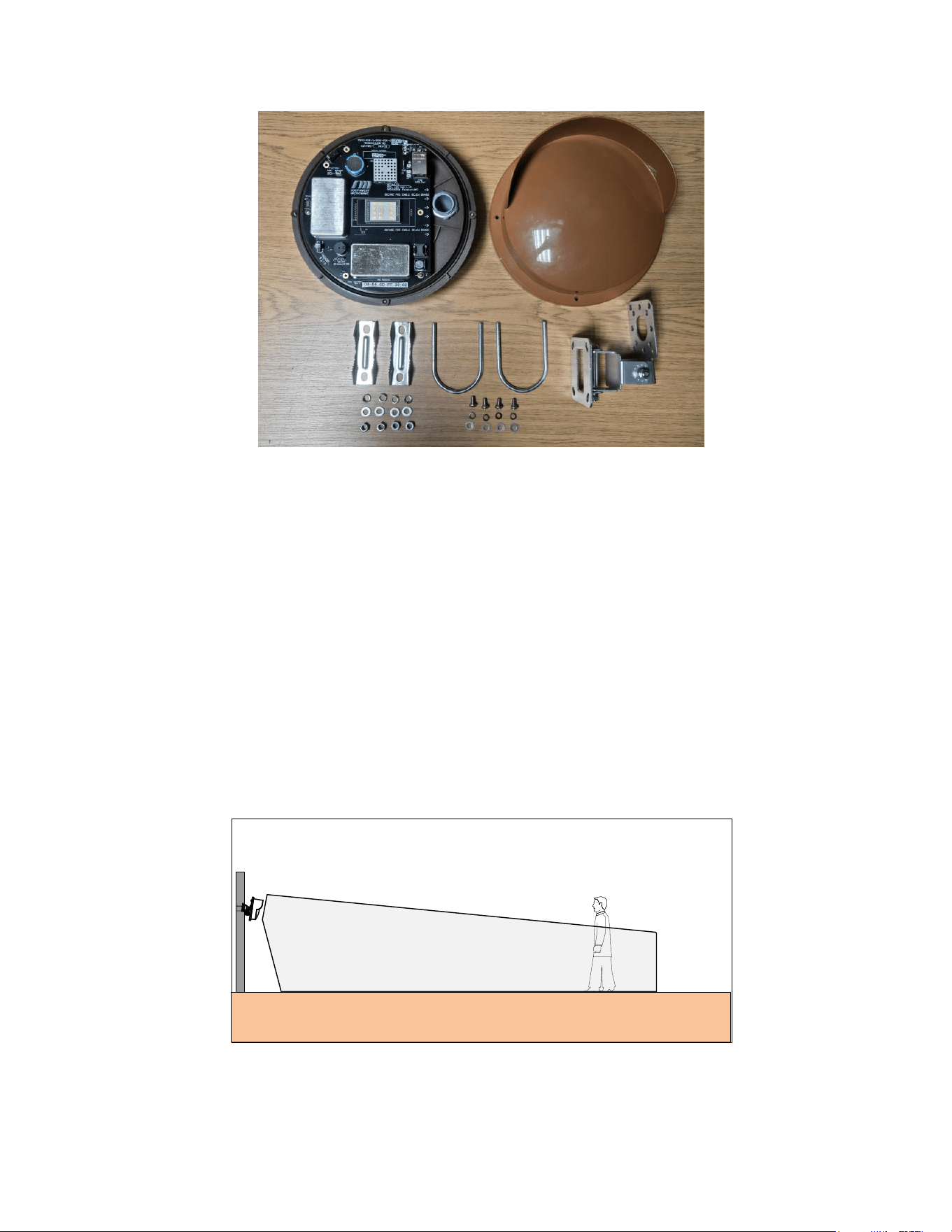
Each Model MS30-POE-S Digital Transceiver includes a Model MS30-POE-S Transceiver and MB30 mounting
bracket as shown in Figure 2.1.
Model MS30-POE-S dimensions are 8.6 in diameter (218mm) and 7.16 in (182mm) front to back (from radome
face to mounting bracket). Each unit weighs 2.75lbs (1.25kg).
Model MS30-POE-S Manual
7 Version 0
Figure 2.1 – Model MS30-POE-S Hardware
3.0 Principles of Operation and Detection
3.1 Description
Model MS30-POE-S includes both transmitter and receiver in a single enclosure. The transmitter radiates
microwave energy that is reflected-back into the receiver by objects within the detection zone as shown in Figure
3.1. The observed detection zone is established by Sensitivity.
A microwave transceiver transmits microwave energy into the detection zone, and objects in the zone reflect energy
back to its’ receiver. Whenever an object is moving, the Doppler Effect shifts the frequency of its reflection, and the
transceiver generates an alarm whenever it detects a frequency shift in the reflected energy.
The size of a frequency-shifted reflection that will cause alarms is varied by the Sensitivity control causing the
detection zone for any object to vary. The detection zone for a large object such as a truck would be larger and for a
small object such as a man would be smaller.
Figure 3.1 – Operation of Model MS30-POE-S
To ensure a continuous perimeter, it is necessary to provide sufficient overlap so that the dead zone immediately
below and behind the sensor is protected.
Model MS30-POE-S Manual
8 Version 0
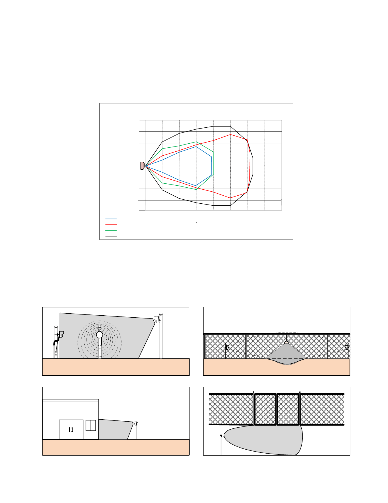
3.2 Range of Operation
Model MS30-POE-S has a maximum range of 32.8 feet (10m) and a maximum width of 35 feet (10.7m) +/- 10% for
an upright walking target when mounted 4 feet (1.2 meters) above smooth earth at 20dB threshold offset with 120º
angle and tilted down at a 10º to 15° angle. The detection angle is adjustable from 30º to 120º. The typical detection
patterns for the 60º and 120º are shown in Figure 3.2
HORIZONTAL FIELD OF VIEW
DISTANCE
5ft (1.5m)
10ft (3m)
15ft (4.5m)
5ft
10ft
(3m)
15ft
(4.5m)
20ft
(6.1m)
25ft
(7.6m)
30ft
(9.1m)
35ft
(10.9m)
WIDTH
5ft (1.5m)
10ft (3m)
15ft (4.5m)
30dB Gain 120º
20dB Gain 120º
20ft (6.1m)
20ft (6.1m)
(1.5m)
30dB Gain 60º
20dB Gain 60º
Figure 3.2 – Typical Pattern
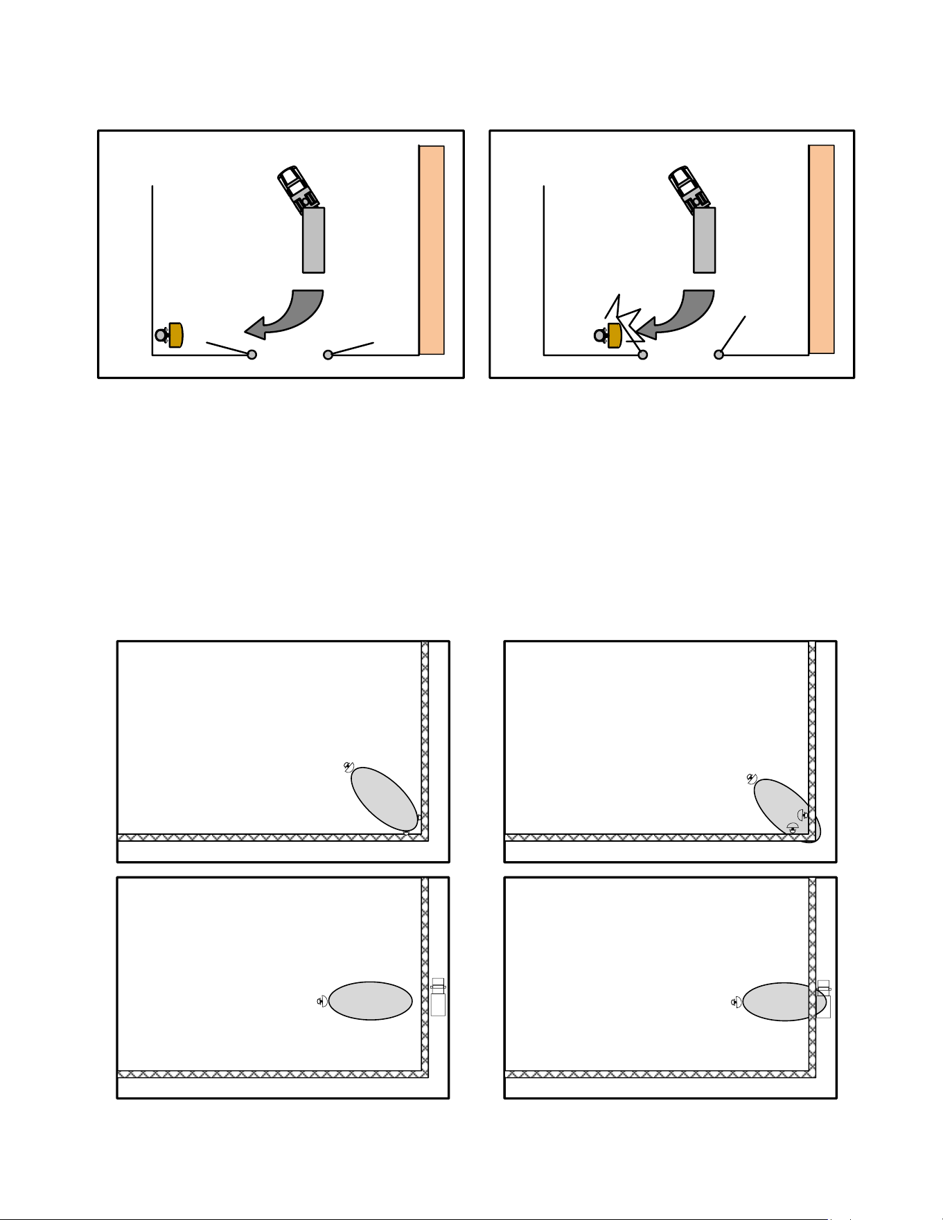
3.3 Applications
Some applications are shown in Figure 3.3 like covering a short corner overlap, filling in a depression in the zone,
securing the side of a building and securing a gate.
PROTECTING SIDE OF BUILDING
SHORT CORNER OVERLAP
DEPRESSION IN PERIMETER
GATE PROTECTION
Figure 3.3 – Applications

Model MS30-POE-S Manual
9 Version 0
3.4 Specifications
1.0 Detection Capability
1.1 Range: 32.8 feet (10m) +/- 10%. Varies somewhat with site reflectivity.
1.2 Beam Diameter: 1 foot (.3m) to 35 feet (10.9m). Varies somewhat with site reflectivity, detection
angle, and threshold offset.
1.3 Target: 77-pound (35kg) human – walking, running, hands and knees crawling or jumping. Prone
crawling or rolling 77-pound (35kg) human or simulated with a 12-inch (30.5cm) diameter metal
sphere detected at maximum range of 25 feet (7.6m) with flat terrain.
1.4 Minimum Target Velocity: 0.2ft. /sec. (.06m/sec.).
1.5 Maximum Target Velocity: 26ft. /sec. (7.9m/sec.).
2.0 Reliability
2.1 Equipment False Alarm Rate: 1/year/unit based upon signal-to-noise ratio at maximum gain setting.
2.2 Probability of Detection: 99% minimum on 77-pound (35kg) human upright or on hands and knees.
3.0 Transmittal Signal
3.1 Radiated Power: +10dBm EIRP.
3.2 Carrier Frequency: K-band 24.050 to 24.250 GHz +/- 50MHz.
3.3 Modulation: FSK.
3.4 The above specifications for the USA are in accordance with F.C.C. regulation’s part 15.249, for CE
EN 300 440 and Canada ISED.
4.0 Power Requirement
4.1 Voltage: 2.18 Watts on startup. 2.56 Watts typical.
4.2 Power over Ethernet, IEE 802.3af, Class 1.
6.0 Hardware LED Indicators:
6.6 Communication LEDs on network port.
7.0 Alarm / Status Indications in IST Software
7.1 Alarm LED.
7.2 Tamper Switch Alarm LED.
8.0 Software Alignment and Test Aids
8.1 Settings Screen.
8.2 Target Screen.
Model MS30-POE-S Manual
10 Version 0
9.0 Communications Port
9.1 1 - Network port for IST, CM-POE-S Controller, GAM, or Third-Party HLI connection.
10.0 Weight: 2.75 pounds (1.25kg). Shipping weight 4.75 pounds (2.15kg).
11.0 Operating Environment
11.1 Temperature: -40° F to +185° F (-40° C to +85° C).
11.2 Relative Humidity: 10 to 90%.
11.3 Altitude Rating: Up to 2000m (6562 feet).
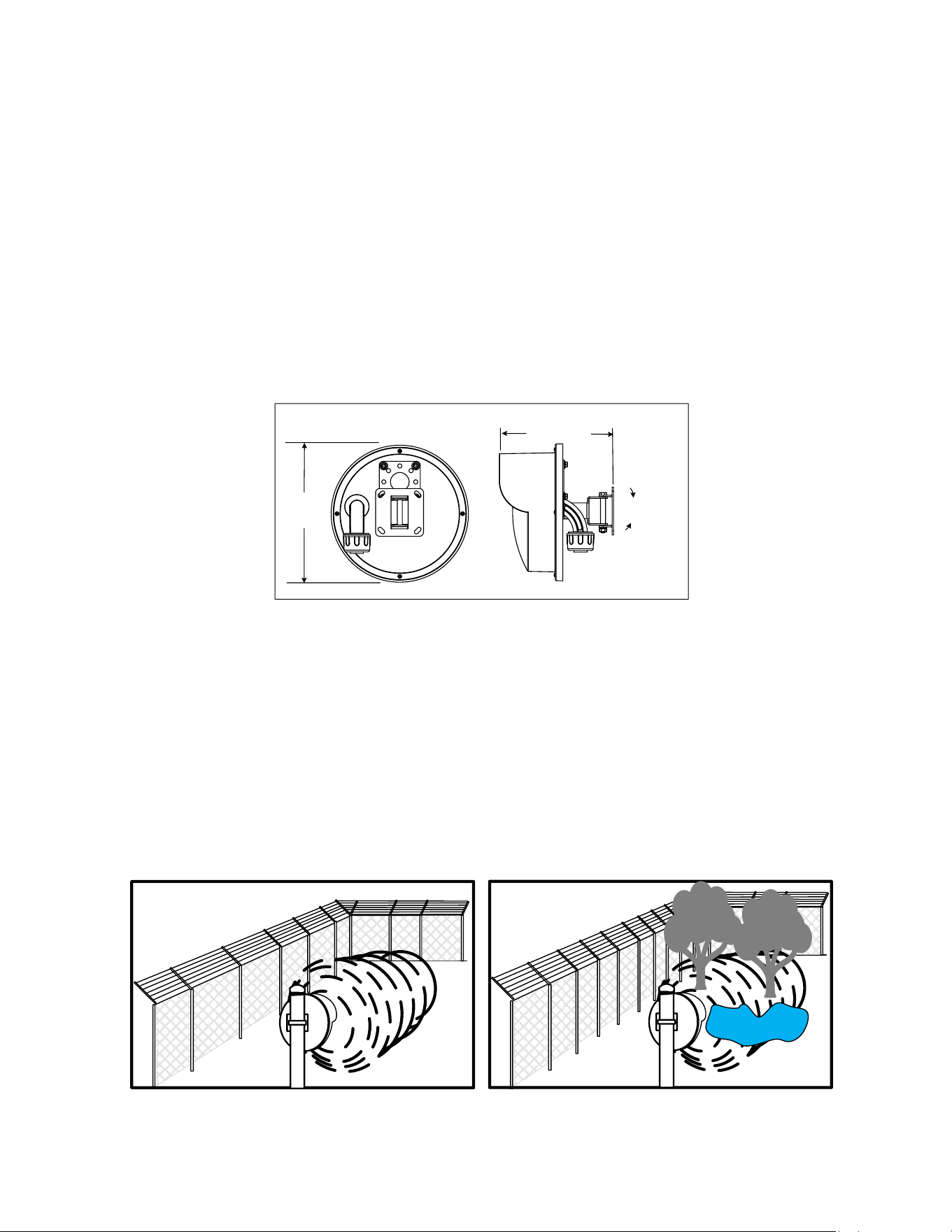
12.0 Dimensions (Motion Sensor – Figure 3.4)
30
o
MAX TILT
UP or DOWN
8.6 in.
(21.8cm)
Dia.
Dimensions
7.16 in (18.2cm)
Figure 3.4 – Model MS30-POE-S Dimensions
4.0 Installation Instructions
4.1 Location of Model MS30-POE-S
4.1.1 Required Area
Model MS30-POE-S must be located in an area which is free of obstruction and moving/vibrating/shaking
objects such as chain link fences parallel/perpendicular to the detection field, metal structures, trees, bushes, tall
grass and large areas of water as shown in Figure 4.1. Large moving objects within the protection pattern will be
indistinguishable from an intruder and will cause nuisance alarms.
DO DONT
Figure 4.1 – Clear Area
Model MS30-POE-S Manual
11 Version 0
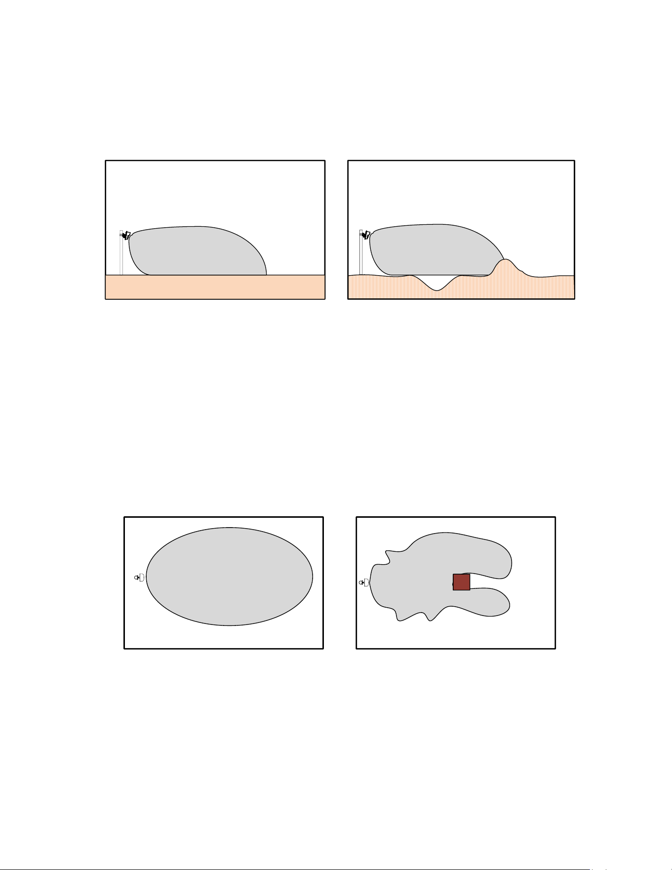
4.1.2 Terrain
The ground must be flat across the protected area. Any bumps, hills or ditches in the area will shadow the beam
and may provide crawl space for an intruder. Bumps or hills must be leveled, and ditches filled so that the area is
flat to within six (6) inches (152mm) Figure 4.2.
DO DONT
Figure 4.2 – Terrain
Provide good drainage. Large puddles may cause nuisance alarms. The protected area can be any stable, reasonably
smooth material such as concrete, asphalt, tilled earth, or gravel.
If there is grass or vegetation in the protected area it must be kept cut to a maximum of three (3) inches (76.2mm)
in height.
Snow accumulation should not exceed three (3) inches (76.2mm) in height. Model MS30-POE-S should not be
operated over open water.
Be aware that large, fixed objects reflect microwave energy and distort the detection zone as shown in Figure 4.3.
Normal Detection Pattern
Distorted Detection Pattern
Figure 4.3 – Obstruction Distortion
When installing Model MS30-POE-S inside buildings, do not illuminate fluorescent lights. Flickering lights may
cause nuisance alarms. Be aware that detection zone patterns may penetrate windows, thin wooden doors or partition
walls.
4.1.3 Physical Protection
Install the motion sensor in locations that provide protection from accidental damage as well as from tampering.
Simple devices such as bumper poles or parking guards may be used to protect equipment from damage from
vehicles as shown in Figure 4.4.
Model MS30-POE-S Manual
12 Version 0
X
X
X
X
X
X
X
X
X
X
X
X
X
X
X
X
X
XX
X
X
X
DO DONT
Figure 4.4 – Physical Protection
4.1.4 Best Security
Choose the location that will provide the best security yet be free from nuisance alarms. Always locate Model
MS30-POE-S inside a controlled access area to prevent unwanted nuisance alarms due to random foot traffic,
vehicles, or large animals. Typically, units should be mounted at a nominal height of 3.5 feet (1.06m) to 4.5 feet
(1.37m) or higher above ground level, and far enough inside fence to provide a clear area of protection.
When Model MS30-POE-S is used inside a fence, always orient the beam so that the detection zone does not include
the fence itself because the fence may move with high winds and cause nuisance alarms as shown in Figure 4.5.
DO DON’T
Figure 4.5 – Best Security
Model MS30-POE-S Manual
13 Version 0
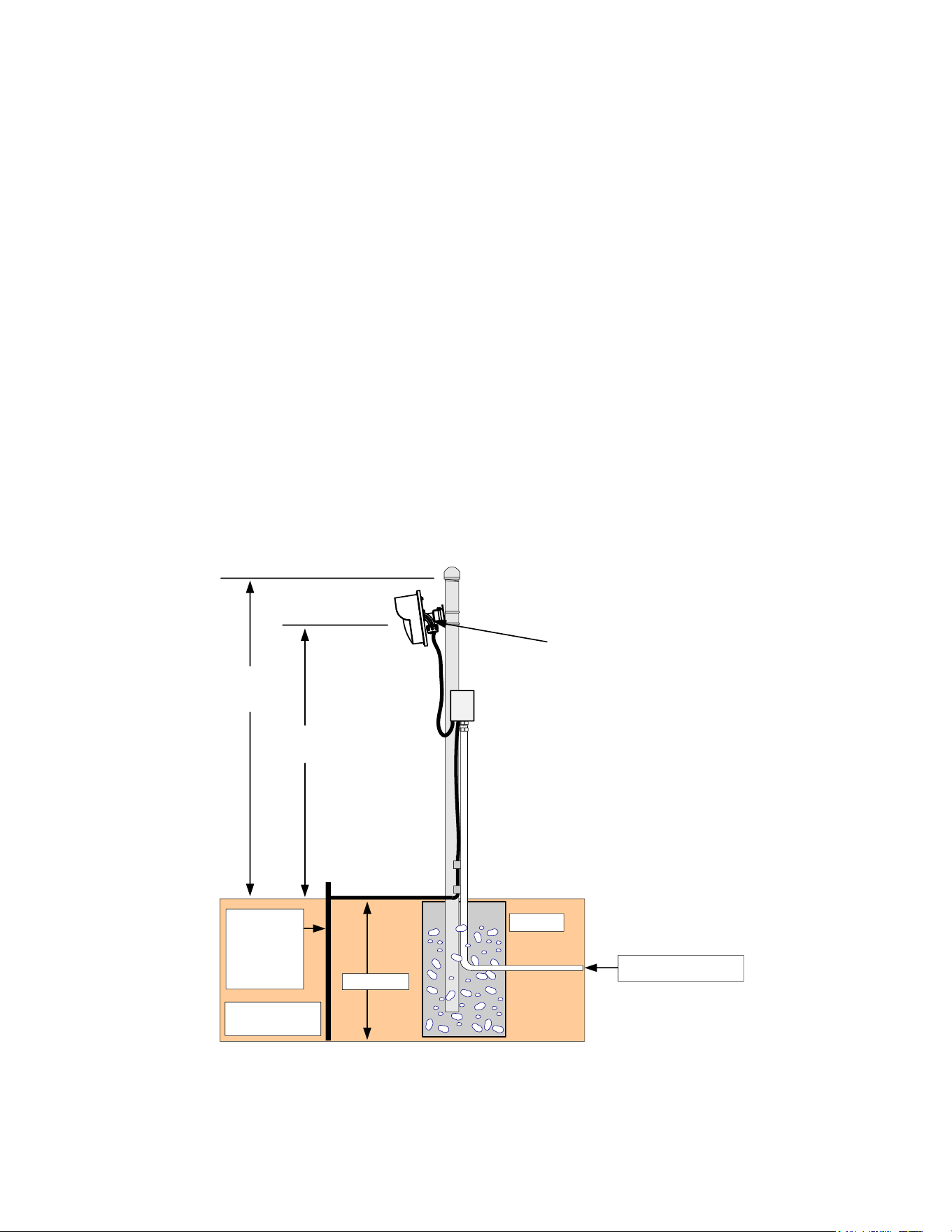
4.2 Mounting Model MS30-POE-S
Prepare a rigid mounting surface for the Model MS30-POE-S motion sensor. Do not mount units on a cyclone
fence or any vibrating surface. A recommended mounting post is a 1.5 to 2.0 inch (38 to 50mm) galvanized pipe
(outside diameter 1.9 to 2.38 inches, 48.4 to 60.5mm), sunk into the ground in a concrete base, and protruding
above ground level to a height of 5 feet (1.52m).
Mount the transceiver at a nominal height of 3.5 (1.06m) to 4.5 feet (1.38m) above ground level (dependent on
detection requirements) and allow for height adjustment of at least plus or minus 1 foot (.31m). Height adjustment
and angle may be required during final alignment to achieve optimum detection. Other mounting heights may be
required for application reasons.
An 18-inch (457mm) ¾ inch (19mm) flex conduit is recommended between conduit fitting of transceiver and
rigid conduit as shown in Figure 4.6.
Model MS30-POE-S may also be mounted to a rigid wall or on the side of a building using the holes in the
mounting plate. It can also be mounted to Unistrut using the holes in the mounting plate. Unistrut will allow for
horizontal or vertical adjustments.
NOTE: DO NOT TOUCH THE ANTENNA…!
Ground Lug
3/4" (19mm)
Flexible
Conduit
1.5" (38mm) O.D.
Galvanized Pipe
Cap
#6 AWG
Ground Bus
Install Per Local
Electrical Code
Concrete
PoE Network Cable
24" (61cm)
Grounding
Rod
per Local
Electrical
Code
3.5' to 4.5' (1.06 to
1.38m) Nominal
5.0'
(1.52m)
Nominal
Junction Box with PoE
Surge Protector
Downward angle of
10º to 15º
Figure 4.6 – Mounting Detail
1. Remove the Model MS30-POE-S transceiver from the shipping container. Open the bags with the
mounting bracket.
Model MS30-POE-S Manual
14 Version 0
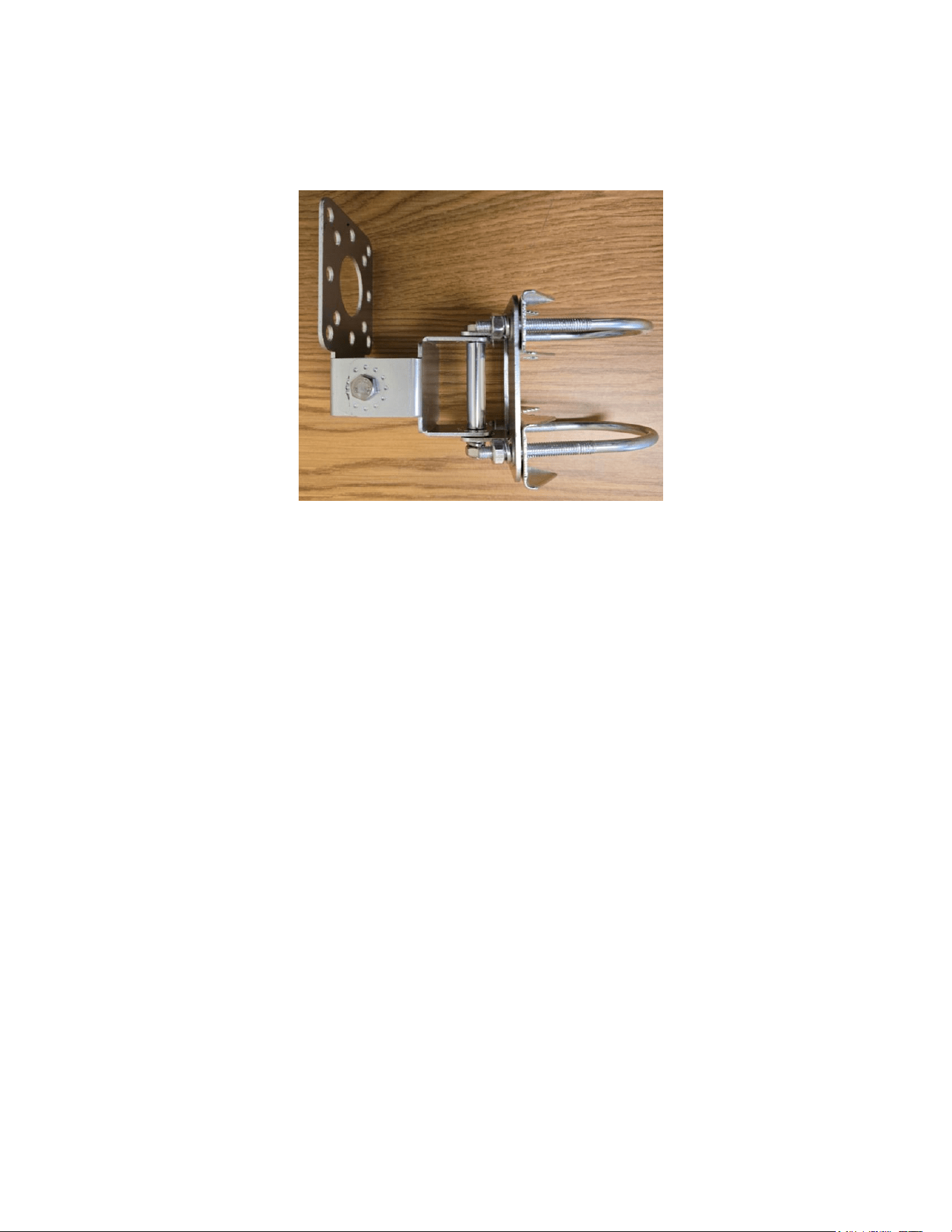
2. Secure the MB30 mounting bracket to the unit with the four (4) provided screws and to the post with the
U-bolts or to other mounting surface with appropriate screws or fasteners. The Mounting Bracket is
shown in Figure 4.7.
Figure 4.7 – MB30 Mounting Bracket
3. Rotate the Model MS30-POE-S transceiver so that the conduit fitting is pointed straight down.
4. After the unit is correctly orientated, tighten all nuts on the mounting bracket to hold the units in place.
5.0 Wiring
5.1 Power Supply
Model MS30-POE-S is a Power over Ethernet (IEEE 802.3af, Class 1) sensor so power is provided by the
network switch. The transceiver is 2.56 Watts typically. A CAT 5 or CAT 6 shielded twisted pair cable is
recommended. The maximum length of cable should not exceed 328 feet (100m). An in-line PoE surge protector
is recommended.
5.2 Communications Wiring
The only communications connection to the Model MS30-POE-S is the Ethernet cable. This port would be used
for connection to the Control Module-POE-S (CM-POE-S), Graphic Alarm Manager (GAM) or any third-party
High-Level Interface (HLI) for alarm annunciation and the Installation Service Tool (IST) for browser setup of
transceiver.
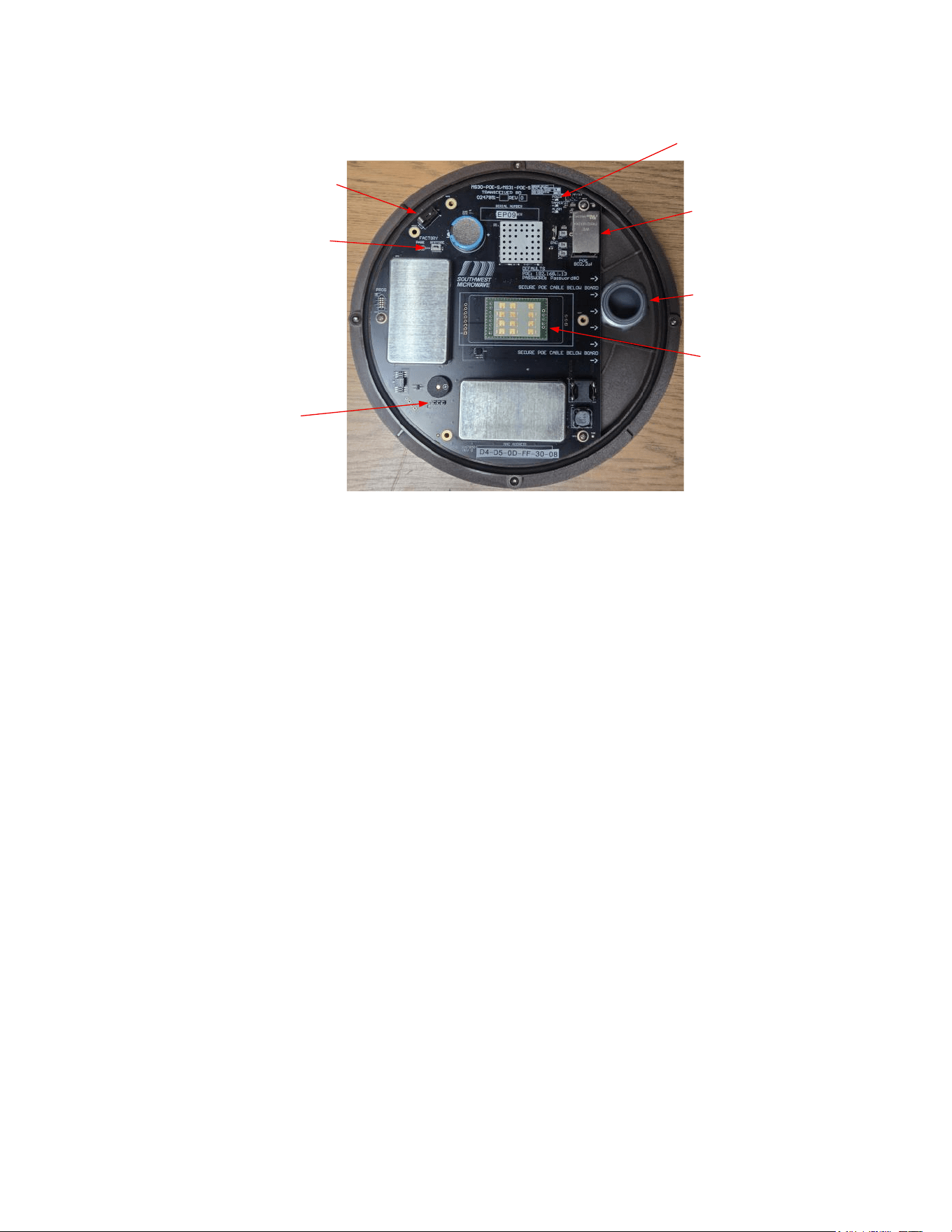
6.0 Circuit Board
6.1 Model MS30-POE-S
The electrical connections for the Model MS30-POE-S board are shown in Figure 6.1. The circuit board has
LEDs for Power On, Intrusion Alarm and Tamper Alarm indication.
Model MS30-POE-S Manual
15 Version 0
LEDs
Antenna
J1, RJ45 port
S1. Tamper Switch
S2,Factory Restore Button
Sonalert Jumper
Conduit
Figure 6.1 – Model MS30-POE-S Circuit Board
6.2 Communications Port
Each Model MS30-POE-S transceiver has one RJ45 network connector. The RJ45 port has LEDs to indicate
communications polling.
Note: each transceiver has a “Factory Restore” button that will set the unit back to default settings. To initiate
the restore: hold down the “S1 tamper switch” and “restore button” for a minimum of ten (10) seconds.
7.0 Connecting the Transceiver
7.1 Model MS30-POE-S Network Connections
1. Remove the radome of Model MS30-POE-S transceiver by removing the four-radome screws.
2. Insert network cable through the ¾ inch (19mm) conduit fitting. Leave enough slack in wire so that
motion sensor may be tilted after radome is replaced. Make sure it does not block the antenna.
3. Attach network cable to connector J1 RJ45 port as shown in Figure 6.1.
4. For protection against unauthorized openings or tampering, a Form C tamper switch is provided.
5. For local testing the buzzer jumper (JP5) can be set to the “ON” position for an audible alarm.
6. Re-install the radome using the four-radome screws.
NOTE: After the wiring is completed, it is recommended that conduit entry be filled (sealed) with non-
corrosive sealant such as Dow-Corning #738 RTV. This will prevent moist air in the conduit system
from entering Model MS30-POE-S transceiver.

Model MS30-POE-S Manual
16 Version 0
8.0 Installation Service Tool (IST) Software
8.1 Introduction
The Installation Service Tool (IST) is software used with INTREPID™ Model MS30-POE-S transceiver. Its
function is to align and configure the detection parameters and network parameters of the transceiver. It is also
used to service and troubleshoot the sensor.
The IST is embedded browser-based software in each transceiver. A web browser such as Firefox, Chrome, or
Edge is required to communicate with the sensors for configuration and maintenance. Only one (1) browser at a
time should be connected.
8.2 IST for Model MS30-POE-S Transceiver
With the network connection established, open the web browser to be used. (Note: the screen captures in this
manual were done using Google Chrome).
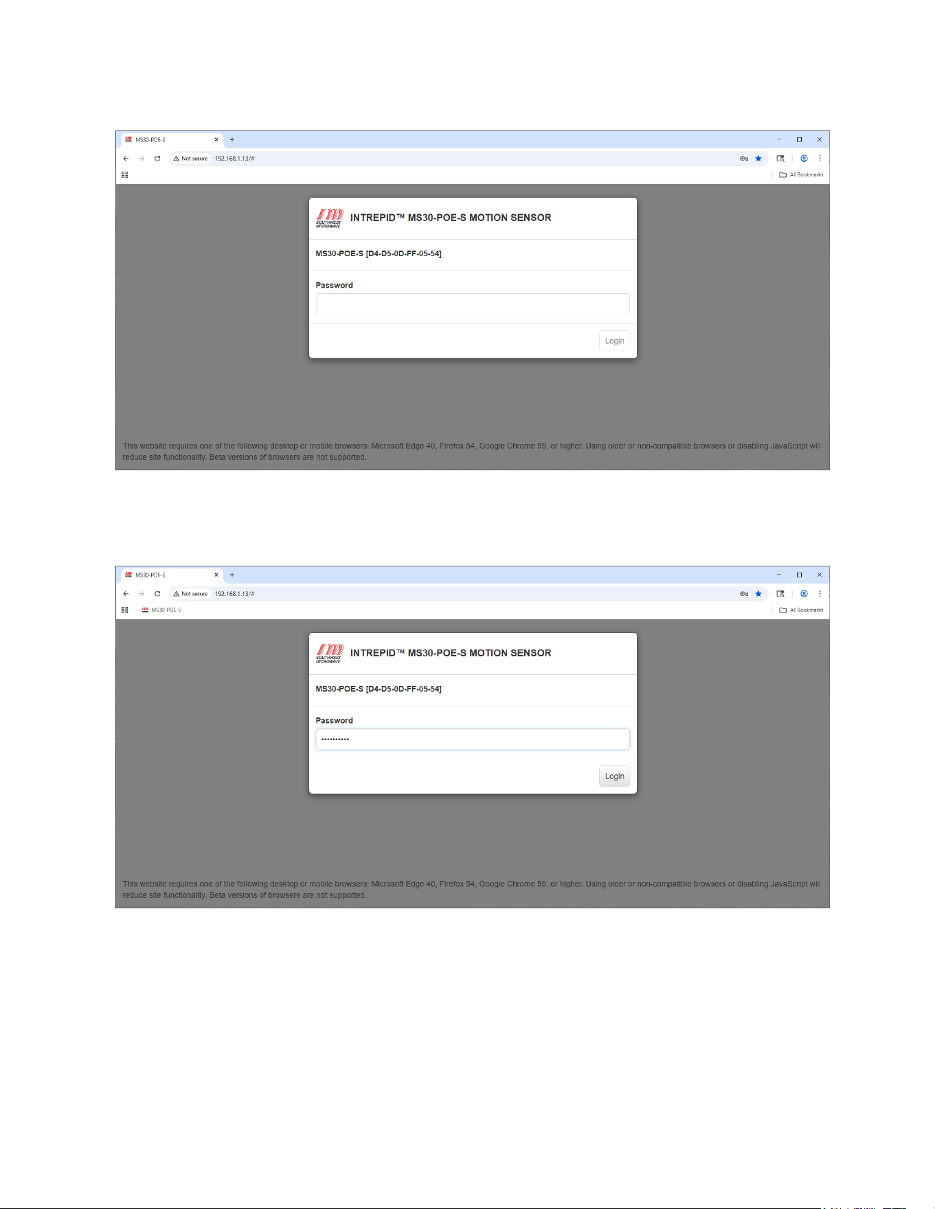
8.2.1 With the browser open, type in the default IP address (192.168.1.13) for the Model MS30-POE-S
transceiver as shown in Figure 8.1.
8.2.2 Once the IP address has been entered and the application started, the INTREPID™ Model MS30-POE-S
motion sensor password dialog box will open as shown in Figure 8.2.
The default password is Password#0. The screen will also display the Model MS30-POE-S and MAC
Address. Note: The password should be changed for security reasons.
At this point the page can be bookmarked for future use as shown in the header of Figure 8.3. Note: If
nothing is being done the browser session will time out and a dialog box will open asking to Logout or
Resume Session.
Figure 8.1 – Main Browser Screen
Model MS30-POE-S Manual
17 Version 0
Figure 8.2 – Login Screen
Enter the password and select “Login” as shown in Figure 16 to start the Model MS30-POE-S IST program.
Figure 8.3 – Login Screen with Password
9.0 Settings Tab
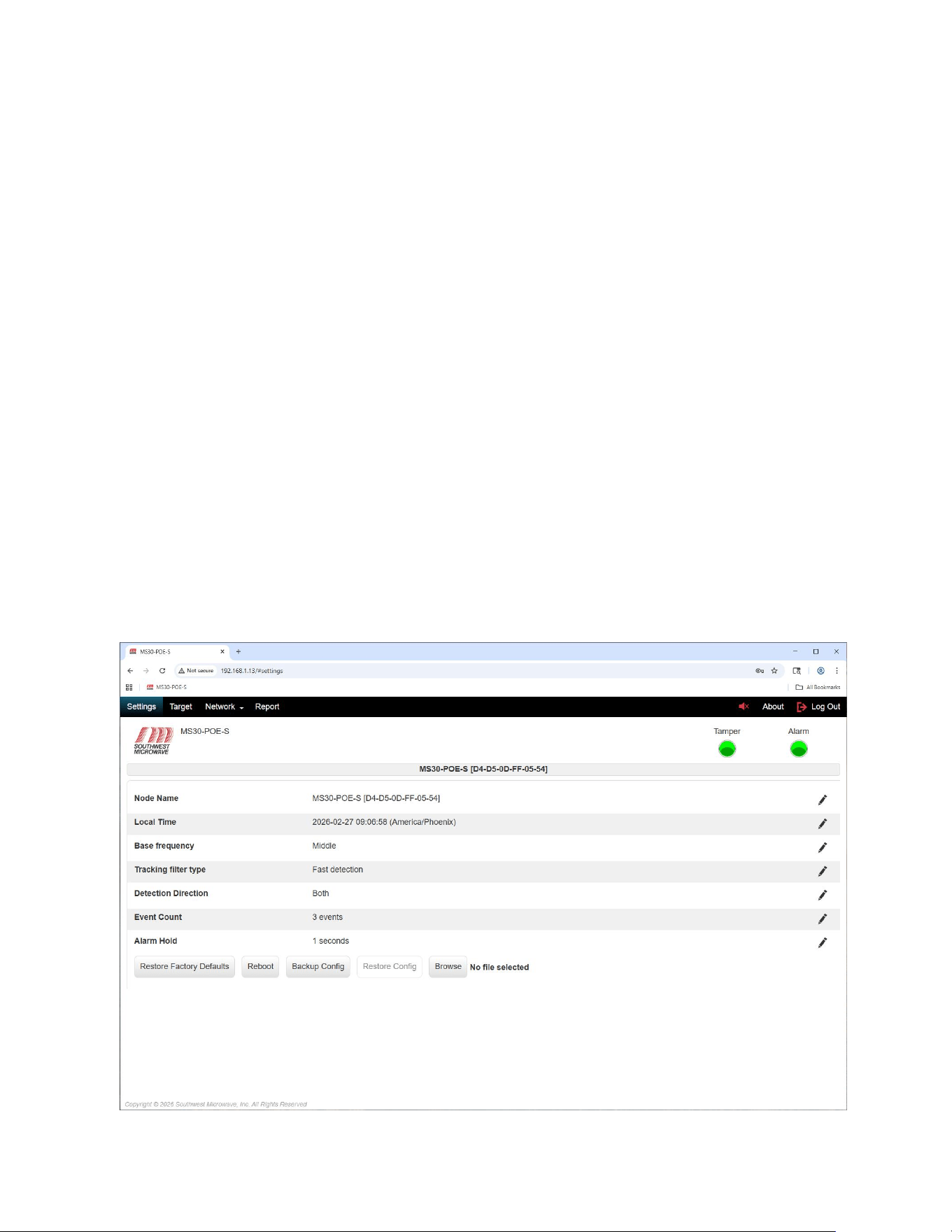
Once the login has been selected the IST will open to the “Settings” screen as shown in Figure 9.1. There are four
(4) tabs that can be selected: Settings, Target, Network and Report. No matter which tab is selected the header and
top banners will always be displayed. There is also an About button and Log Out button.
The “Settings” screen will display:
Model MS30-POE-S Manual
18 Version 0
➢ Node Name: A unique name that can be given to the motion sensor. (Maximum of 64 characters).
➢ Local Time: Local Time set from a computer.
➢ Alarm Hold: The hold time for an alarm relay or graphic display to be held before resetting.
➢ Base Frequency: RF frequency selection to minimize interference between transceivers.
➢ Tracking filter type: Selection for medium and high security applications.
➢ Detection Direction: Selector for detection direction.
➢ Event Count: Selector for events required to declare an alarm.
➢ Alarm Hold: Selector for setting the time duration the unit stays in alarm.
➢ Restore Factory Defaults: A button to restore the transceiver to factory default settings.
➢ Reboot: Sends a software command to restart the sensor like powering down and up.
➢ Backup Config: Creates backup configuration file of motion sensor settings.
➢ Restore Config: File for restoring motion sensor settings.
➢ Browse: Button used to find saved Backup Configuration file. Used with Restore Config.
Figure 9.1 – Settings Screen
Model MS30-POE-S Manual
19 Version 0
The screen will also display the:
➢ Browser header.
➢ The Southwest Microwave logo.
➢ The sensor model connected (in this case Model MS30-POE-S).
➢ About button: Shows software number, version and build date. Also used to update software.
➢ Log Out button: Allows logging off the sensor.
➢ Tamper LED: Shows the status of the tampers switch on the sensor.
➢ Alarm LED: Show when the unit has an intrusion alarm.
➢ Seven Pencil Icons: Used to edit parameters.
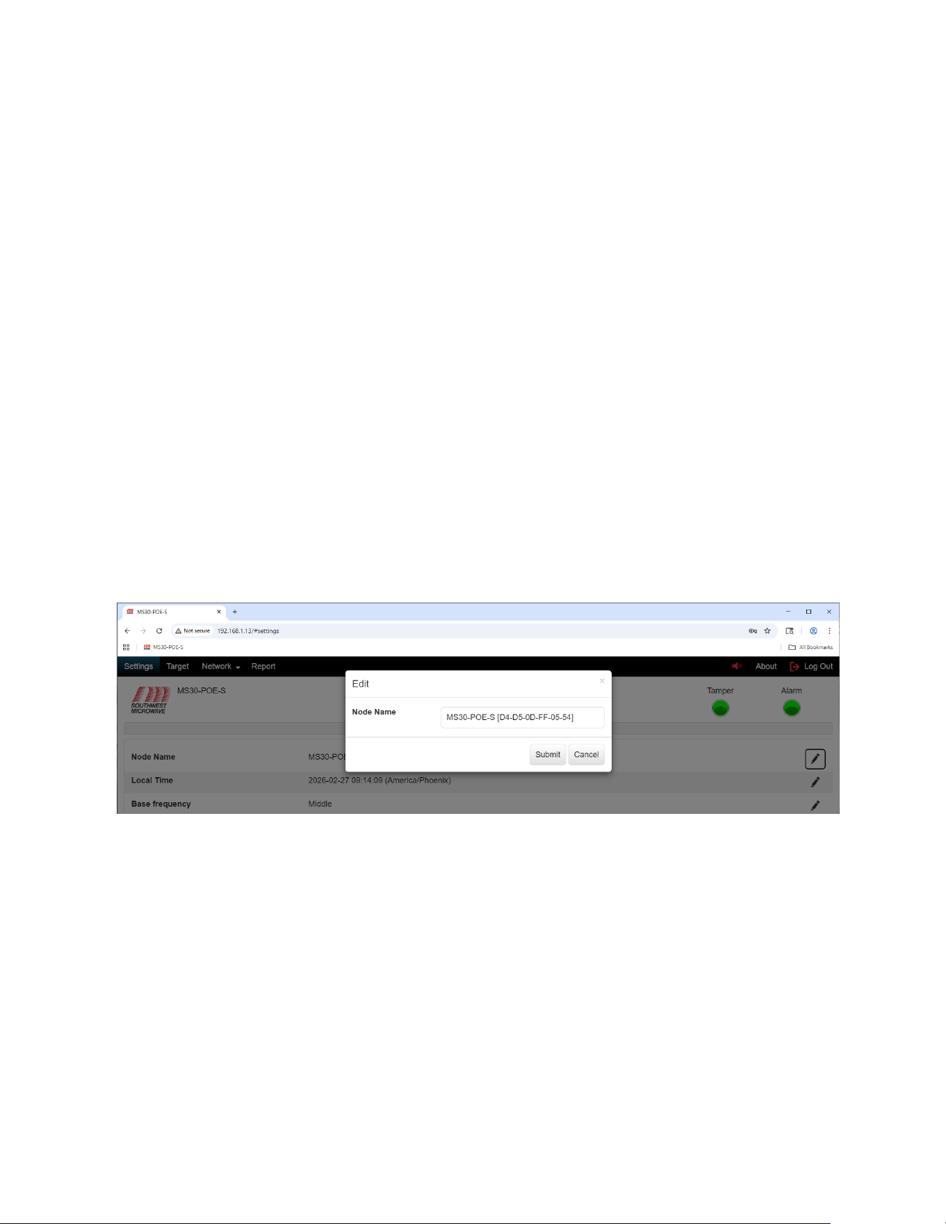
9.1 Node Name
To edit the Node Name select the pencil icon at the end of the node name field (far right on screen) to open the
“Edit Node Name” dialog box as shown in Figure 9.2. The default name is Model MS30-POE-S with the MAC
address.
Figure 9.2 – Edit Node Name
Enter an appropriate or unique name for this transceiver. The name can be 64 characters in length. In this example
it was entered as Model MS30-POE-S. Once complete, select the “Submit” button to save the name. The
“Cancel” button will end the task. It will now be displayed in the Node Name field and banner.
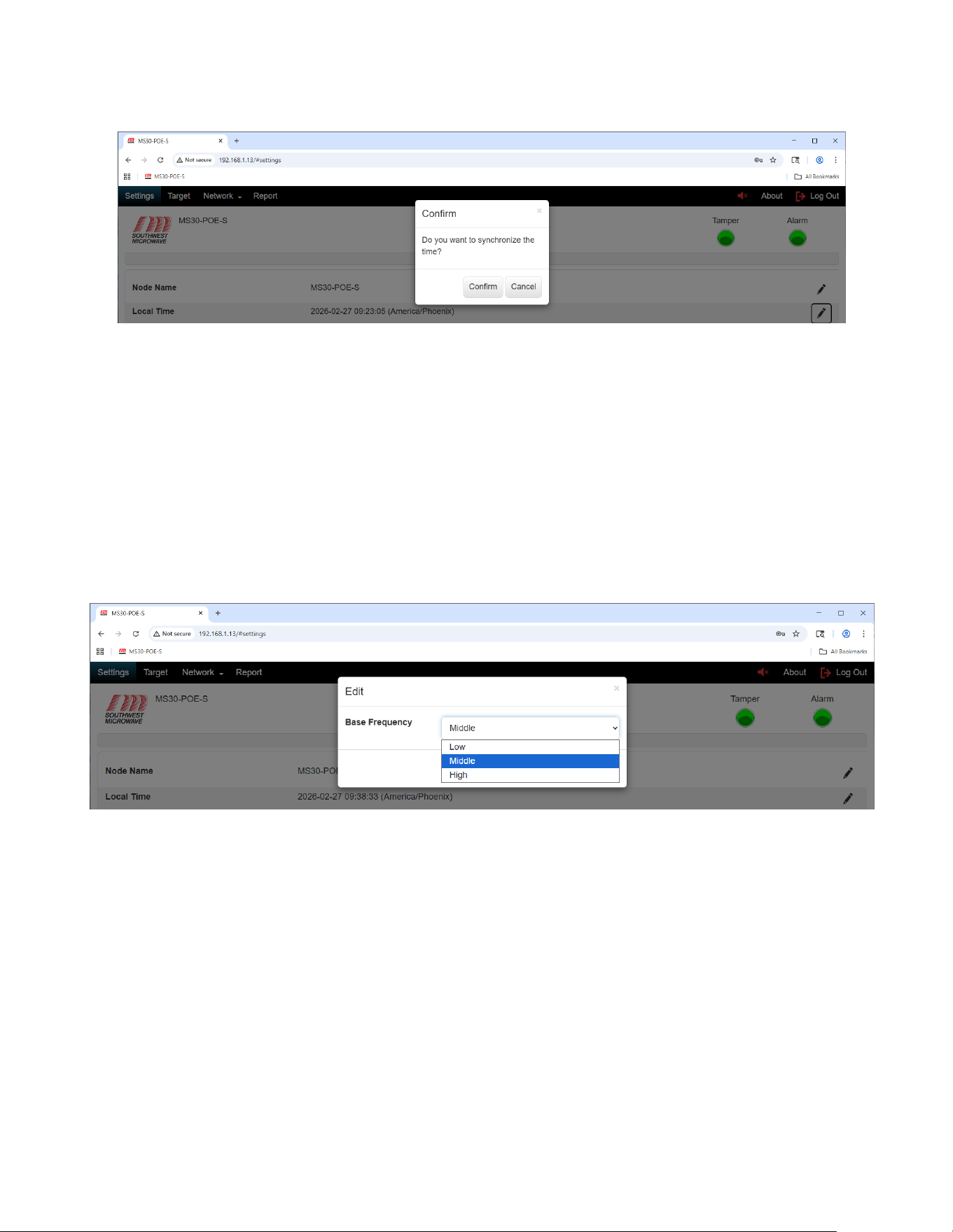
9.2 Local Time
To edit the Local Time select the pencil icon at the end of the local time field (far right on screen) to open the
“Confirm” dialog box as shown in Figure 9.3.
This will synchronize the time to the connected browser device. Note: this must be done before making any
other adjustments or settings to the system for it to operate correctly
Select “Confirm” to update the time. Select “Cancel” to end the task.
Model MS30-POE-S Manual
20 Version 0
Figure 9.3 – Local Time
9.3 Base Frequency
To edit the “Base Frequency” select the pencil icon at the end of the Base frequency field (far right on screen) to
open the “Base Frequency Edit” dialog box. Select the pull-down menu to display the three (3) settings as shown
in Figure 9.4. The selections are Low, Medium, and High. This selection is used when multiple units are used
near each other or looking back at each other to minimize mutual interference. Medium is default. The low and
high staggers the frequency below or above the medium.
Select the appropriate setting required then select the “Submit” button to update the change. Select the “Cancel”
button to end the task.
Figure 9.4 – Base Frequency
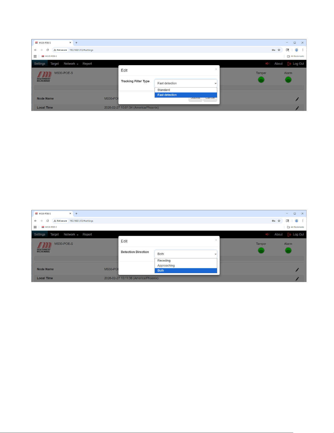
9.4 Tracking Filter Type
To edit the “Tracking Filter Type” select the pencil icon at the end of the Tracking filter type field (far right on
screen) to open the “Tracking Filter Type Edit” dialog box. Select the pull-down menu to display the two (2)
settings as shown in Figure 9.5. The selections are Standard and Fast Detection.
The Standard setting is used for low and medium applications where detection of a walking and running target is
required. Fast detection is used for high security applications where detection of walking, running, jumping, and
commando belly crawling targets are required.
Select the appropriate setting required then select the “Submit” button to update the change. Select the “Cancel”
button to end the task.
Model MS30-POE-S Manual
21 Version 0
Figure 9.5 – Tracking Filter Type
9.5 Detection Direction
To edit the “Detection Direction” select the pencil icon at the end of the Detection Direction field (far right on
screen) to open the “Detection Direction Edit” dialog box. Select the pull-down menu to display the three (3)
settings as shown in Figure 9.6. The selections are Receding, Approaching, and Both. Receding will only detect
targets moving away from the sensor, approaching will only detect targets moving towards the sensor, and both
will detect targets moving in both directions.
Select the appropriate setting required then select the “Submit” button to update the change. Select the “Cancel”
button to end the task.
Figure 9.6 – Detection Direction
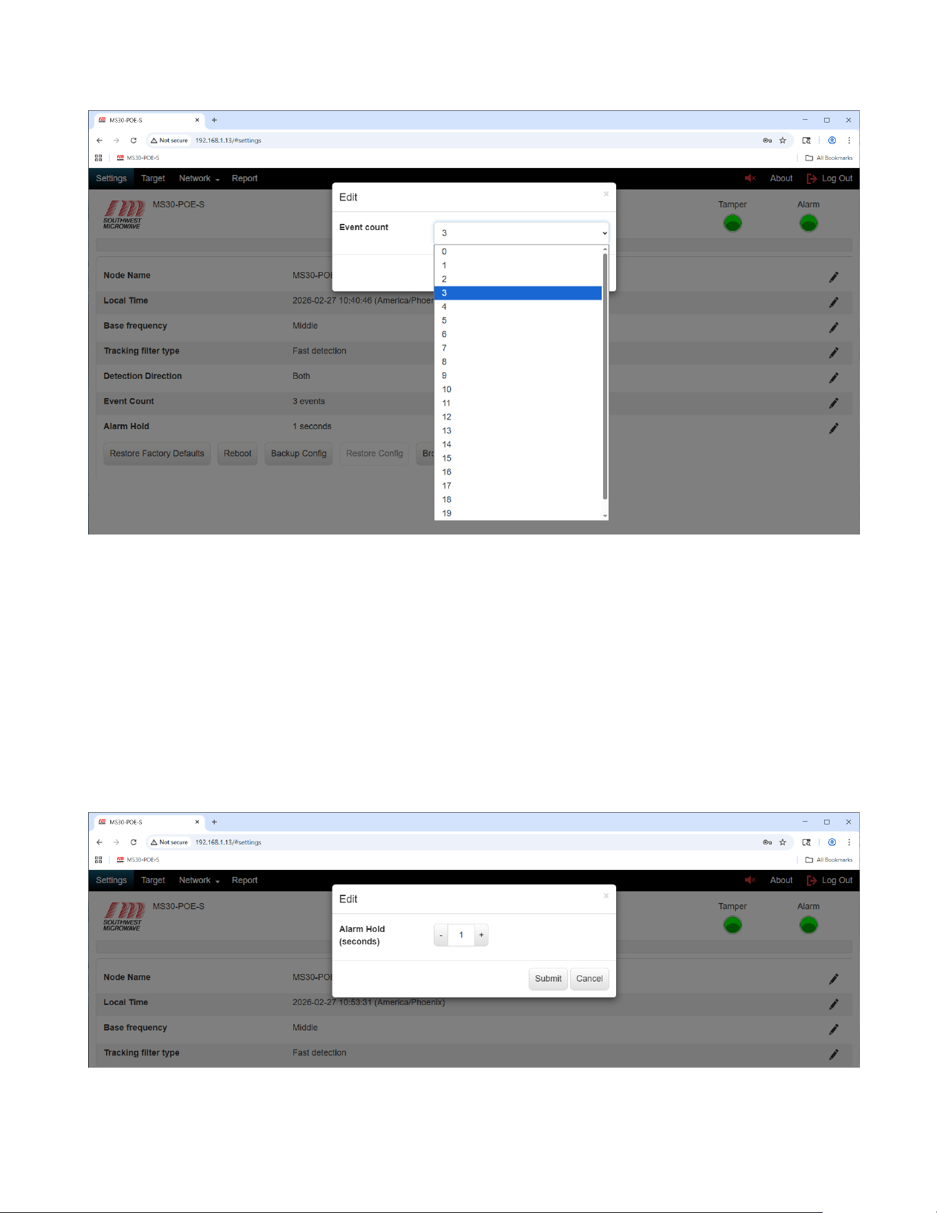
9.6 Event Count
The “Event Count” is an embedded algorithm to qualify targets as alarms and help minimize nuisance alarms. It
controls the event integrator before the threshold circuit. It can be set from 0 to 20. The default is 3. The smaller
the setting the more sensitive the unit will become and have the potential for nuisance alarms.
To edit the Event Count, select the pencil icon at the end of the Event Count field (far right on screen) to open the
“Event Count Edit” dialog box. Select the pull-down menu to display the twenty (20) settings as shown in Figure
9.7. Select the appropriate setting per site requirements and select the “Submit” button to set it. Select the
“Cancel” button to end the task.
Model MS30-POE-S Manual
22 Version 0
Figure 9.7 – Event Count
9.7 Alarm Hold
To edit the “Alarm Hold” time, select the pencil icon at the end of the Alarm Hold field (far right on screen) to
open the “Alarm Hold Edit” dialog box as shown in Figure 9.8.
The “Alarm Hold” is adjustable from 1 to 60 seconds. The default time is 1second. This function sets the time
duration that an alarm will be held in the sensor and keeps a relay or graphics engaged.
Set the time required then select the “Submit” button to update the change. Select the “Cancel” button to end the
task.
Figure 9.8 – Alarm Hold Time
Model MS30-POE-S Manual
23 Version 0
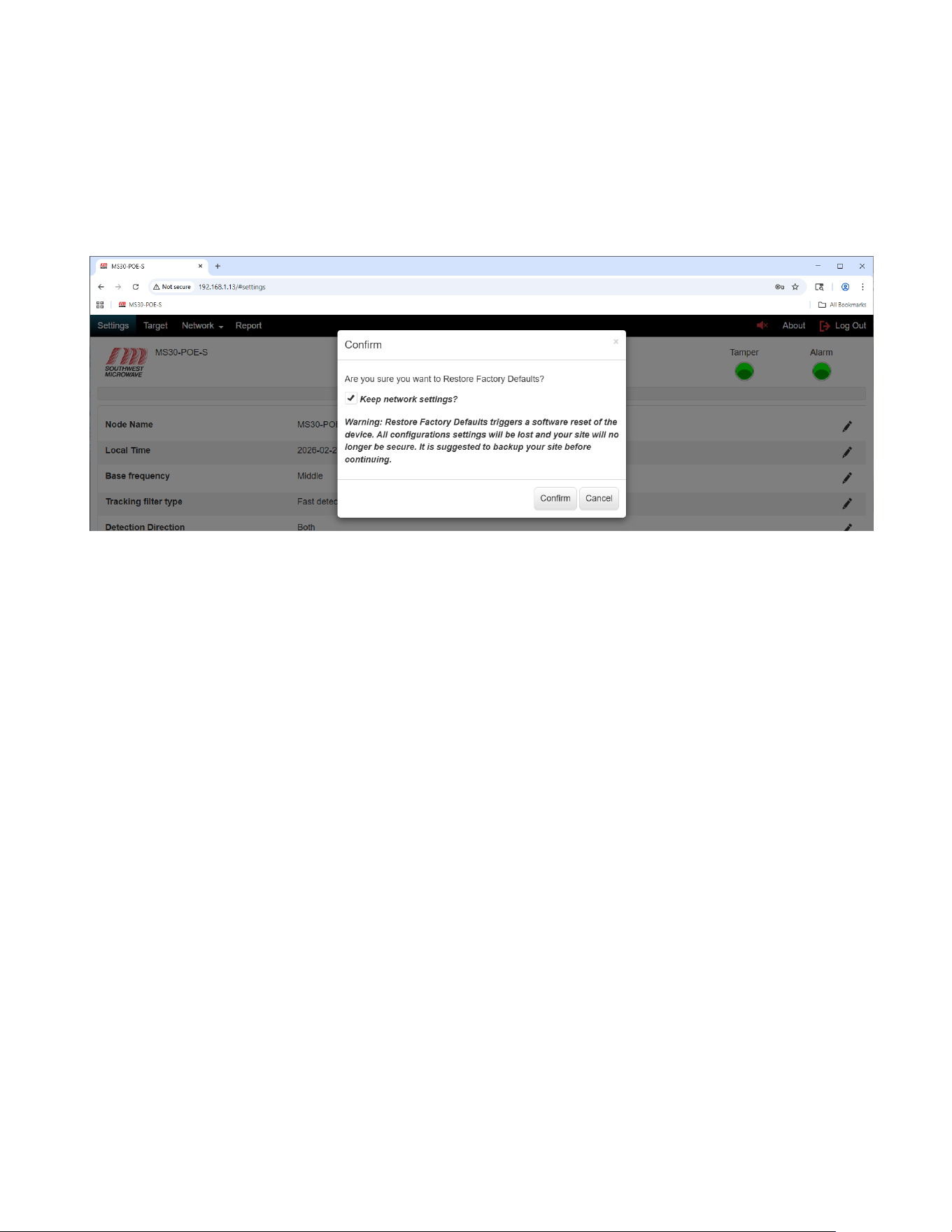
9.8 Restore Factory Defaults
To restore factory defaults into the Model MS30-POE-S transceiver, select the “Restore Factory Defaults” button
to open the restore factory defaults dialog box as shown in Figure 9.9. This should be done before any parameters
are configured to ensure there is no erroneous data in the unit.
Figure 9.9 – Restore Factory Defaults
The dialog box will state “Are you sure you want to Restore Factory Defaults?” with a “Confirm” and “Cancel”
button. There will also be a check box asking, “Keep network settings?” If network settings have been changed
and they are not to be erased, select the check box. With the check box un-selected, the network settings will
return to default.
There will also be a warning displayed stating: “Warning: Restore Factory Defaults triggers a software reset of
the device. All configurations’ settings will be lost and your site will no longer be secure. It is suggested to
backup your site before continuing”.
Select the “Confirm” button to restore defaults. A dialog box will open stating the restore was successful and
return to the Login screen after the session reloads. Select the “Cancel” button to end the task.
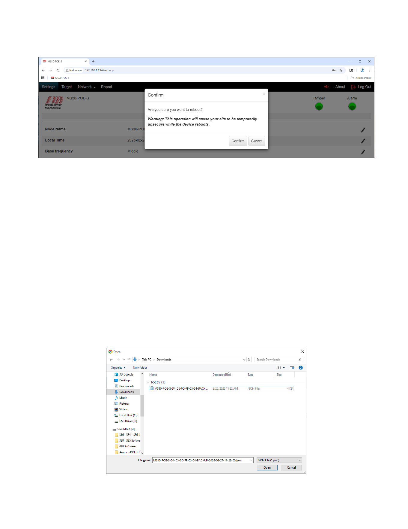
9.9 Reboot
To reboot the sensor, select the “Reboot” button to open the dialog box as shown in Figure 9.10. The dialog box
will state “Are you sure you want to reboot”? The reboot command is a software command to restart the
microprocessor.
There will also be a warning displayed stating: “Warning: This operation will cause your site to be temporarily
unsecure while the device reboots”.
To reboot the sensor, select the “Confirm” button. Selecting the “Cancel” button will end the task. After a reboot
you will be returned to the Login screen.
Model MS30-POE-S Manual
24 Version 0
Figure 9.10 – Reboot Sensor
9.10 Backup Configuration
After all programming of the Model MS30-POE-S has been completed, select the “Backup Config” button to
create a backup file.
The backup command will create a backup file in a *.json format to the “Downloads” folder on the PC. The file
name will be MODEL-MS30-POE-S-MAC ADDRESS-BACKUP, date, and time. In example: MODEL-MS30-
POE-S-D4-D5-0D-FF-05-54-BACKUP-2026-02-27-08-14-05.json.
Other information to the file name can be added if desired.
Select “Save” to save the file.
9.11 Restore Configuration
To restore a saved file to a Model MS30-POE-S, select the “Browse” button to open the Windows dialog box as
shown in Figure 9.11. This should be the “Downloads” folder on the PC where the backup file was saved and
should be in a *.json format. Find the saved file and select “Open”.
Figure 9.11 – Find Restore Configuration File
Model MS30-POE-S Manual
25 Version 0
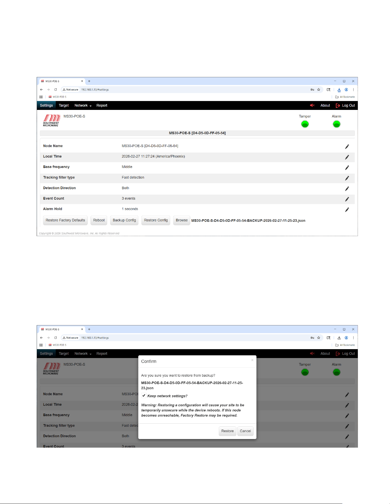
Once the file is opened it will be displayed on the screen as shown in Figure 9.12 and the “Restore Config” button
will become active. Make sure it is the correct file and select “Restore Config”.
Figure 9.12 – Restore Configuration
A “Confirm” dialog box will open asking “Are you sure you want to restore from backup?” as shown in Figure
9.13. It will also list the file that was selected and a check box to “Keep Network Settings”. If the network settings
are not to be changed, select the check box.
There will also be a warning displayed stating: “Warning: Restoring a configuration will cause your site to be
temporarily unsecure while the device reboots. If this node becomes unreachable, Factory Restore may be
required”. Select “Restore” to load the backup or “Cancel” to end the task.
Figure 9.13 – Confirm Restore Configuration
Model MS30-POE-S Manual
26 Version 0
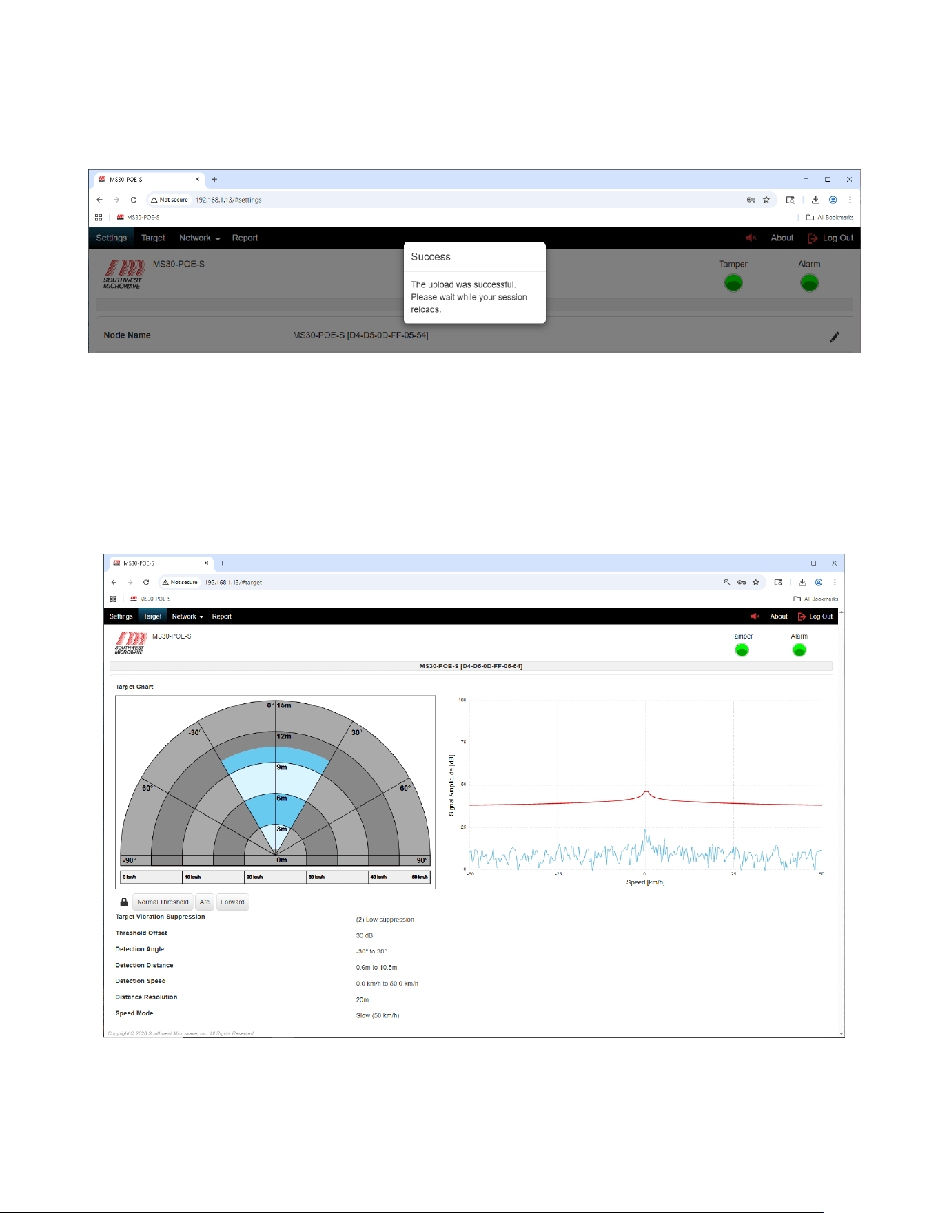
When the restore is complete a dialog box will open stating that it was successful as shown in Figure 9.14. Wait
for the session to reload before continuing which will take you back to the Login screen.
Figure 9.14 – Restore Successful
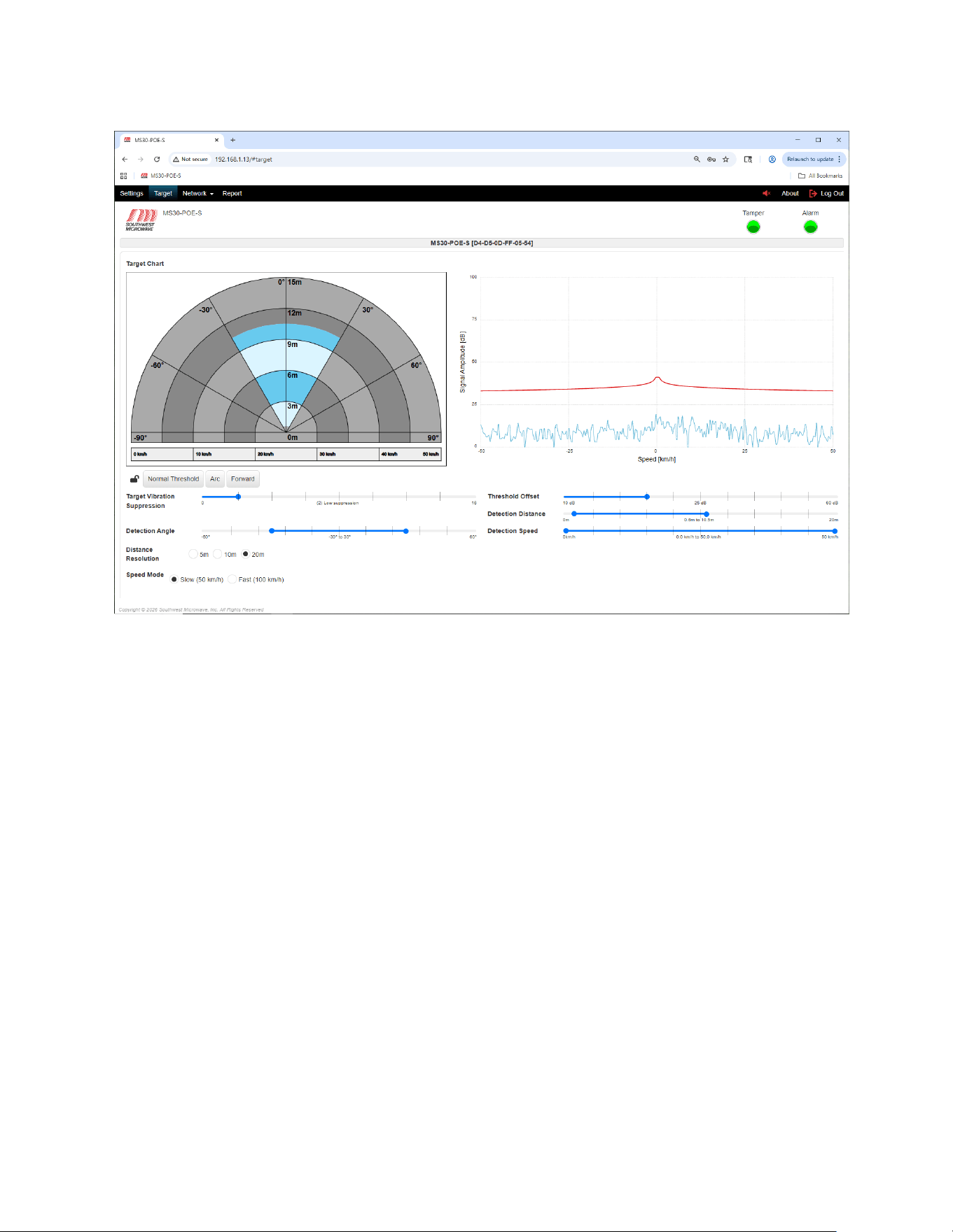
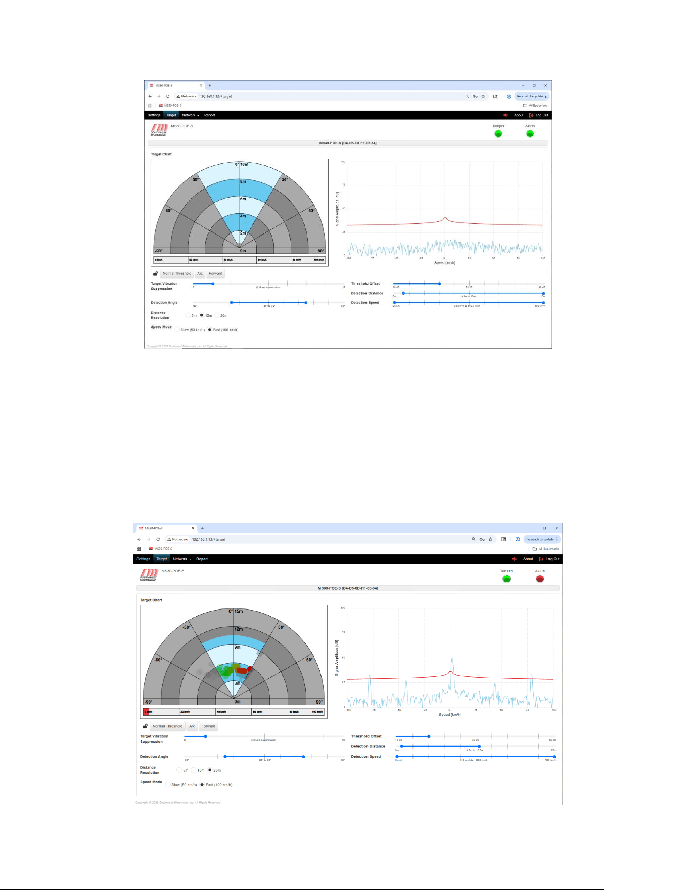
10.0 Target Tab
Selecting the “Target” tab will open the detection screen for MS30-POE-S transceiver as shown in Figure 10.1.
This tab will be used to set the system parameters for Target Vibration Suppression, Threshold Offset, Detection
Angle, Detection Distance, Detection Speed, Distance Resolution and Speed Mode. The “Target Chart” view can
also be changed to an Arc or Forward.
Figure 10.1 – Target Screen
Selecting the “Lock”: under the “Target Chart” will open the slide bars to configure the parameters of the system
as shown in Figure 10.2.
Model MS30-POE-S Manual
27 Version 0
Figure 10.2 – Target Screen Adjustments
10.1 Target Vibration Suppression
The Target Vibration Suppression setting is used to suppress small moving or vibrating targets like weeds, tree
branches, and fences from causing nuisance alarms. The default setting is 2 (low suppression). It can be adjusted
from 0 (no suppression) to 18 (high suppression) as shown in Figure 10.2. Note: at high suppression settings
target detection will be affected.
10.2 Threshold Offset
The Threshold Offset setting is used to change the sensitivity of the unit. The default setting is 30dB. It can be
adjusted from 10dB (most sensitive) to 60dB least sensitive). As shown in Figure 10.2. This setting should be set
at the highest dB value to meet detection requirements of the site to minimize nuisance alarms. As the value is
changed, the red line on the Signal Amplitude chart will move up or down above the system noise floor. Note:
setting the value at 10dB will make the unit very sensitive and become prone to nuisance alarms. 15dB is usually
the lowest setting.
10.3 Detection Angle
The Detection Angle setting is used to change the angle of the detection area from 30° to 120° as shown in Figure
10.2. Default is 60°. When changed the blue area of the Target Chart will shift with the new setting. Set the angle
to meet site requirements.
Model MS30-POE-S Manual
28 Version 0
10.4 Detection Distance
The Detection Distance setting is used to change the detection distance range as shown in Figure 10.2. Default is
0.6m to 10.5m (1.97 ft. to 34.4 ft.). The 0.6m (1.97 ft.) setting acts like a null at the radome to prevent nuisance
alarms from in close targets like rain. The 10.5m (34.4 ft.) setting is the ideal setting for the range the sensor was
designed to detect. Generally, this setting should not be changed and should never be set to greater than 12m (39.4
ft.). The total adjustment range of the slider is 0m to 20m (0 ft. to 65.6 ft.). If the distance is changed, the blue
area of the Target Chart will shift with the new setting. Set the distance to meet site requirements.
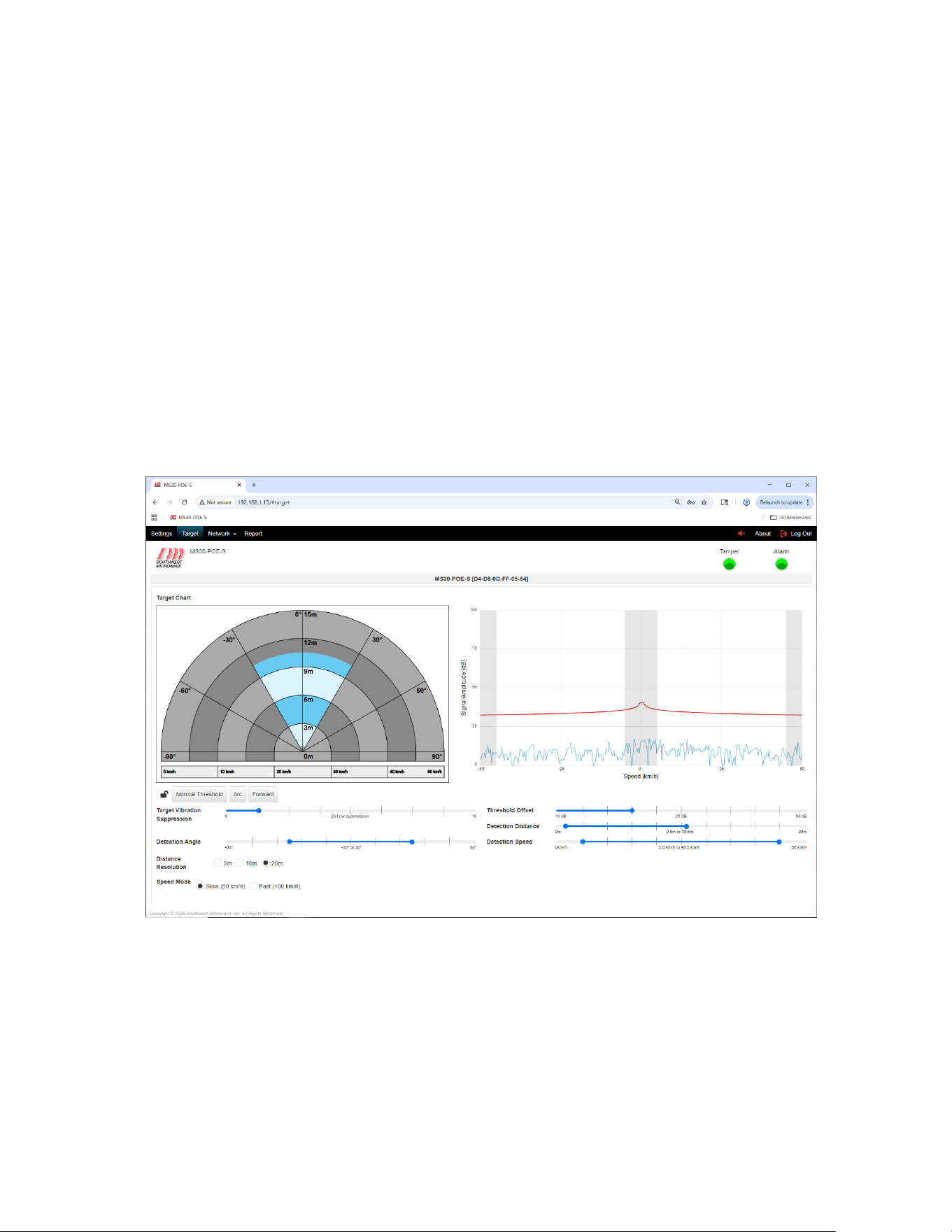
10.5 Detection Speed
The Detection Speed setting is used to change the speed of target detection as shown in Figure 10.2. Default is
0.km/h to 50km/h (0mp/h. to 31mp/h).). The speed can be changed to meet site requirements. If the detection
speed is changed the Signal Amplitude chart will display gray boxes on the areas that have been changed as
shown in Figure 10.3. The Speed Mode has two (2) settings that work in conjunction with the Detection Speed.
These are Slow (50km/h) and Fast (100km/h). The default is Slow. When set to Fast the detection speed will
change to 0.km/h to 100km/h (0mp/h. to 62.1mp/h).). Set the speed to meet site requirements.
Figure 10.3 – Detection Speed Change
10.6 Distance Resolution
The Distance Resolution setting is used to change the Target Chart distances view as shown in Figure 10.2. There
are three (3) resolutions to choose from, 5m, 10m, 20m. When selected the blue area of the Target Chart will
change as shown in Figure 10.4. These settings are just for visual viewing of the range and targets on the screen
and have nothing to do with detection parameters. If set to 20m remember to adjust the setting to 12m or less.
Model MS30-POE-S Manual
29 Version 0
Figure 10.4 – Distance Resolution Change
After all parameters have been set, select the “Lock” icon to lock all the parameters.
10.7 Target Detection
When a target passes through the detection area it will be tracked and create an alarm as shown in Figure 10.5.
The red dots are the alarms, and the alarm LED is illuminated. The green dots are tracking dots and show the
direction the target came from. If the target is outside the detection angle and being seen it will be displayed as
gray dots.
Figure 10.4 – Target Detection
Model MS30-POE-S Manual
30 Version 0
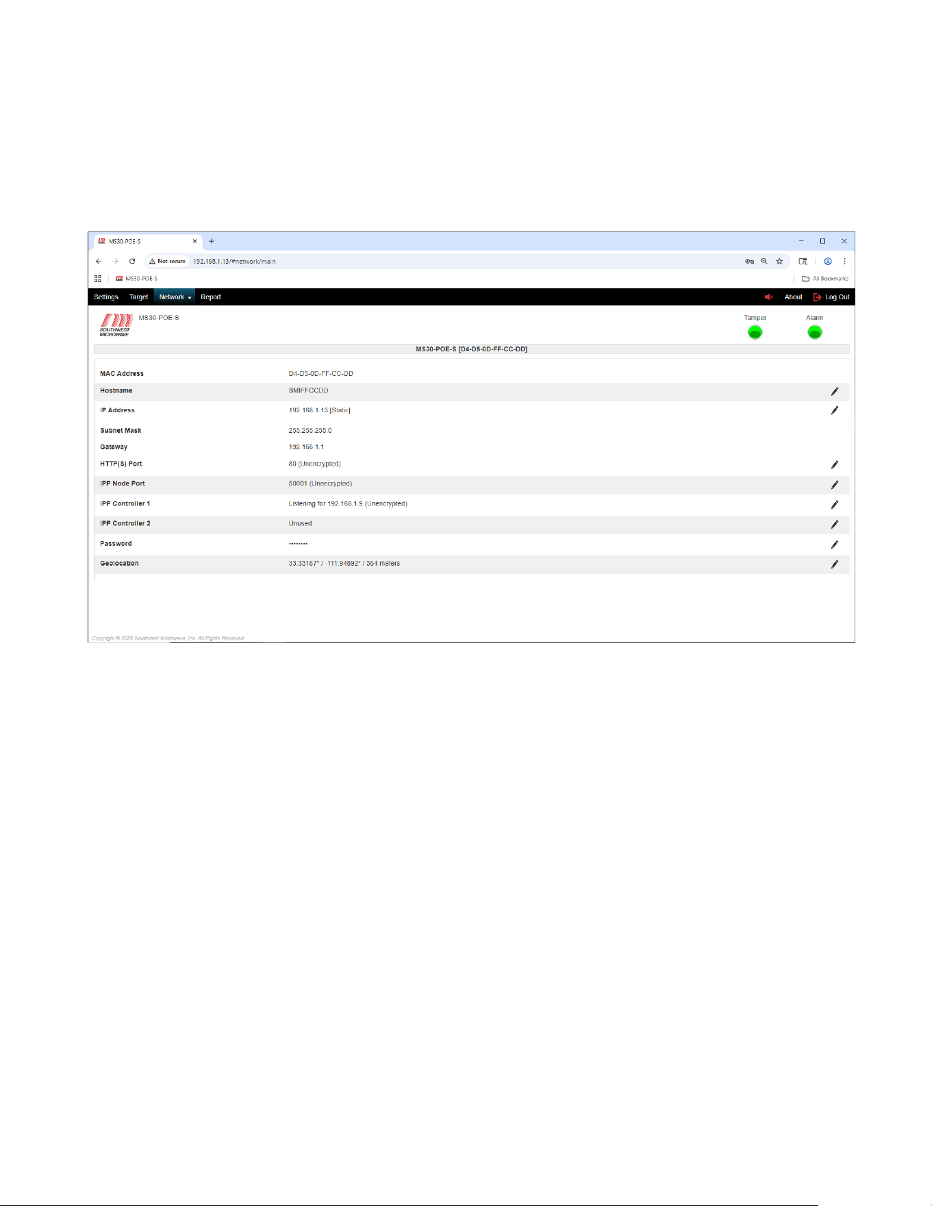
11.0 Network Tab
Selecting the “Network” tab will open the “Main” and MQTT pull down menu. Select “Main” to open the
network parameters screen as shown in Figure 11.1. This screen will be used to set up the network parameters of
the Model MS30-POE-S transceiver.
Figure 11.1 – Network
The screen will display:
➢ MAC Address: The media access control address. (The MAC Address cannot be changed).
➢ Hostname: The archaically node name.
➢ IP Address: The internet protocol address.
➢ Subnet Mask: The mask is used to determine what subnet an IP address belongs to.
➢ Gateway: Node on a network that serves as an entrance to another network.
➢ HTTP(S) Port: The default port for the browser.
➢ IPP Node Port: The INTREPID Polling Protocol Port.
➢ IPP Controller 1: Port for controller or poll master for the sensor such as the CM-POE-S, GAM, or HLI.
➢ IPP Controller 2: Port for controller or poll master for the sensor such as the CM-POE-S, GAM, or HLI.
➢ Password: The user password to connect to the sensor. The password must be a minimum of eight (8)
characters and include one upper case letter (A-Z), one lower case letter (a-z), one digit (0-9) and one
special character (!#$%). The maximum length is sixteen (16) characters.
➢ Geolocation: Provides latitude, longitude, and altitude GPS coordinates.
➢ Pencil icons: Icon used to edit parameters.
Model MS30-POE-S Manual
31 Version 0
11.1 MAC Address
The MAC Address (media access control address) will be the unique address listed for this device. It
will be displayed in a structure such as D4-D5-0D-FF-05-54. This address can-not be edited.
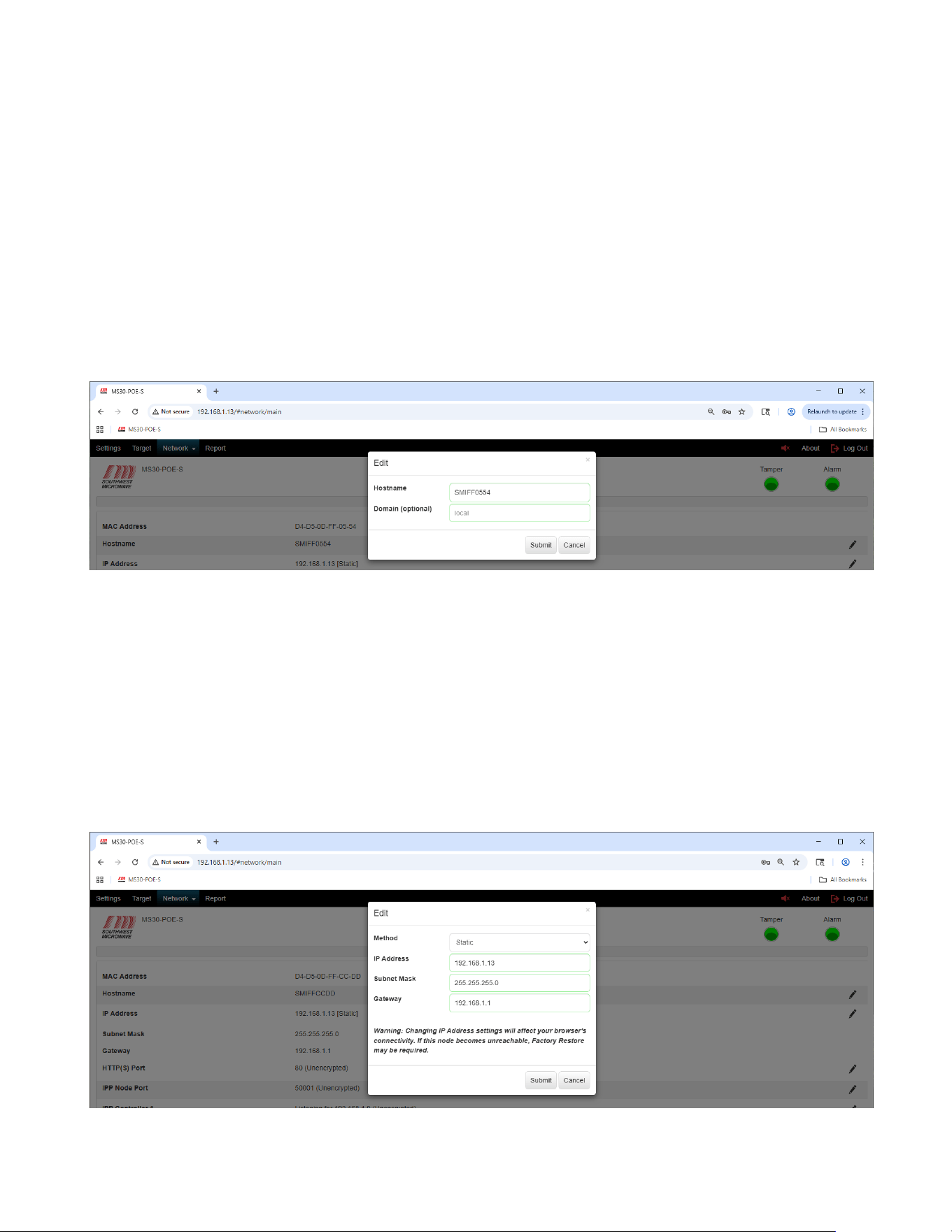
11.2 Host Name
To edit the “Host Name” select the pencil icon on the right of the screen to open the “Edit Host Name and
Domain” dialog box as shown in Figure 11.2. Enter the appropriate information and select the “Submit” button to
update the changes.
Select the “Cancel” button to end the task.
Figure 11.2 – Edit Hostname and Domain
11.3 IP Address
To edit the “IP Address” select the pencil icon on the right of the screen to open the “Edit IP Address, Subnet
Mask Gateway and Method” dialog box as shown in Figure 11.3. Enter the appropriate information and select the
“Submit” button to update the changes. Method is either “Static” or “DHCP”. Select the “Cancel” button to end
the task. If the address is changed, you will need to re-connect using the new address.
A warning will be displayed stating: “Warning: Changing IP Address settings will affect your browsers
connectivity. If the node becomes unreachable, Factory Restore may be required”.
Figure 11.3 – Edit IP Address, Subnet Mask and Gateway
Model MS30-POE-S Manual
32 Version 0
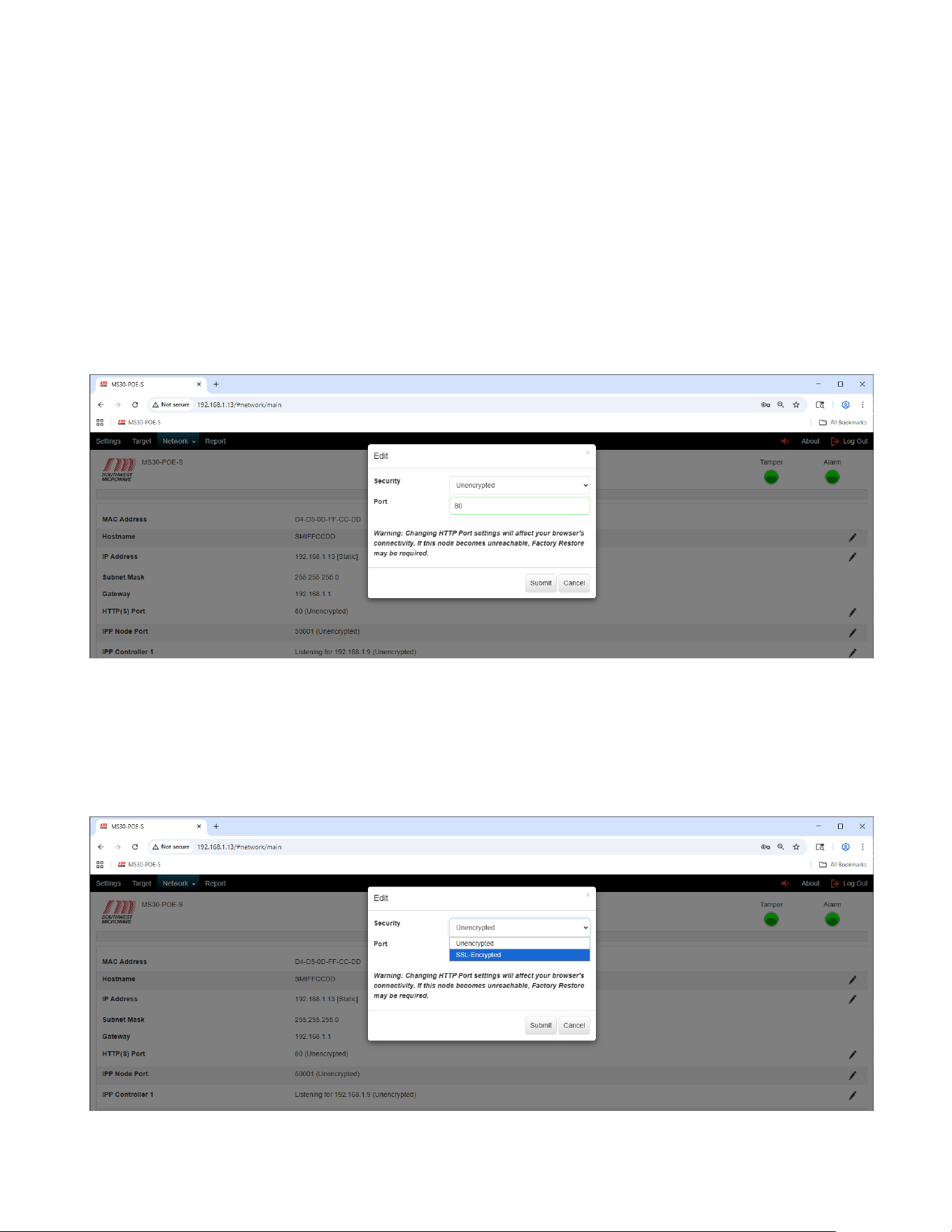
11.4 HTTP(S) Port
To edit and enable the “HTTP(S) Port” select the pencil icon on the right of the screen to open the “Edit
HTTP(S)” dialog box as shown in Figure 11.4. This Edit box will allow enabling or disabling encryption. The
default port number is 80. Selecting the field will display the valid port ranges of 49152 to 65535.
Enter the appropriate security and port information and select the “Submit” button to update the changes. Select
the “Cancel” button to end the task.
A warning will be displayed stating: “Warning: Changing HTTP Port settings will affect your browsers
connectivity. If the node becomes unreachable, Factory Restore may be required”.
Figure 11.4 – HTTP(S) Port
To edit the security of the “HTTP(S) Port” select the “Security” pull down menu to open the SSL-Encrypted
setting as shown in Figure 11.5. The default setting is “Unencrypted”.
The implementation of the SSL-Encryption and use of certificates will be discussed in Section 15.1.
Figure 11.5 – HTTP(S) Port Encryption
Model MS30-POE-S Manual
33 Version 0
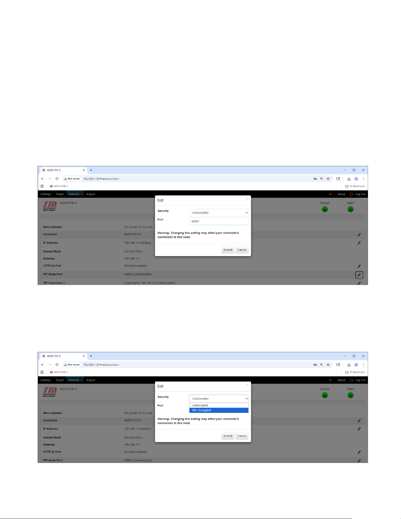
11.5 IPP Node Port
To edit the “IPP Node Port” select the pencil icon on the right of the screen to open the “Edit IPP Node Port”
dialog box as shown in Figure 11.6. This Edit box will allow enabling or disabling encryption of the port and
assigning the port number.
This is the INTREPID™ Polling Protocol (IPP) port. The default port is 50001. Selecting the field will display the
valid port ranges of 49152 to 65535. Enter the appropriate port information and select the “Submit” button to
update the changes. Select the “Cancel” button to end the task.
A warning will be displayed stating: “Warning: Changing this setting may affect your controller’s connection
to this node”.
Figure 11.6 – Edit IPP Node Port
To edit the security of the “IPP Node Port” select the “Security” pull down menu to open the SSL-Encrypted
setting as shown in Figure 11.7. The default setting is “Unencrypted”.
The implementation of the SSL-Encryption and use of certificates will be discussed in Section 15.2.
Figure 11.7 – Edit IPP Node Encryption
Model MS30-POE-S Manual
34 Version 0
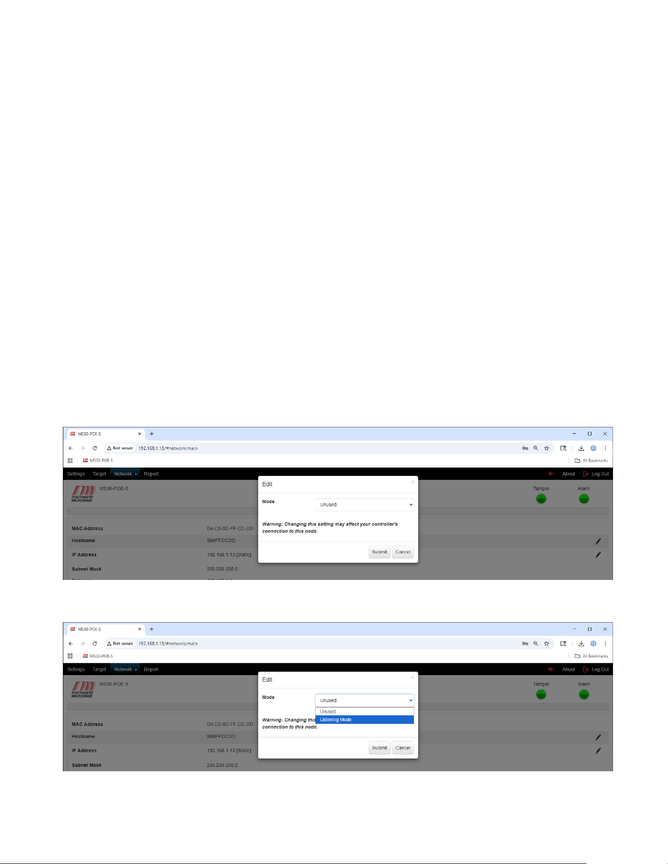
11.6 IPP Controller 1 and IPP Controller 2
To edit the mode of the “IPP Controller 1” or “IPP Controller 2” port select the pencil icon on the right of the
screen to open the “Edit IPP Controller” dialog box as shown in Figure 11.8. This Edit box will allow setting the
port to “Unused” “or “Listening Mode” (passive) for a controller connection as shown in Figure 11.9. Note: IPP
Controller Port 1 and IPP Controller Port 2 are configured the same way.
In the “Listening Mode” the MS30-POE-S is listening for a controller to establish a connection. When Listening
Mode is selected the “Edit Listening Mode” dialog box will open as shown in Figure 11.10. Ensure the
“Operation” is set to “Enabled” for the connection to be established. Select “Disabled” to turn off the port. Enter
the IP Address of the controller that Model MS30-POE-S should be listening for in the “Controller IP Address”
field.
A warning will be displayed stating: “Warning: Changing this setting may affect your controller’s connection
to this node”.
Select the “Submit” button to update the changes. Select the “Cancel” button to end the task.
Note: If you use the CM-POE-S controller the information will automatically be inserted and enabled by the
CM-POE-S controller into the first available unused port.
Note: Controller Port 1 and Controller Port 2 will also be used by HLI development using the POE SDK
document for alarm monitoring. A maximum of two (2) HLI’s can be connected at the same time.
Figure 11.8 – Edit IPP Controller Port
Figure 11.9 – Edit IPP Controller Port Mode
Model MS30-POE-S Manual
35 Version 0
Figure 11.10 – Edit IPP Controller Port Listening Mode
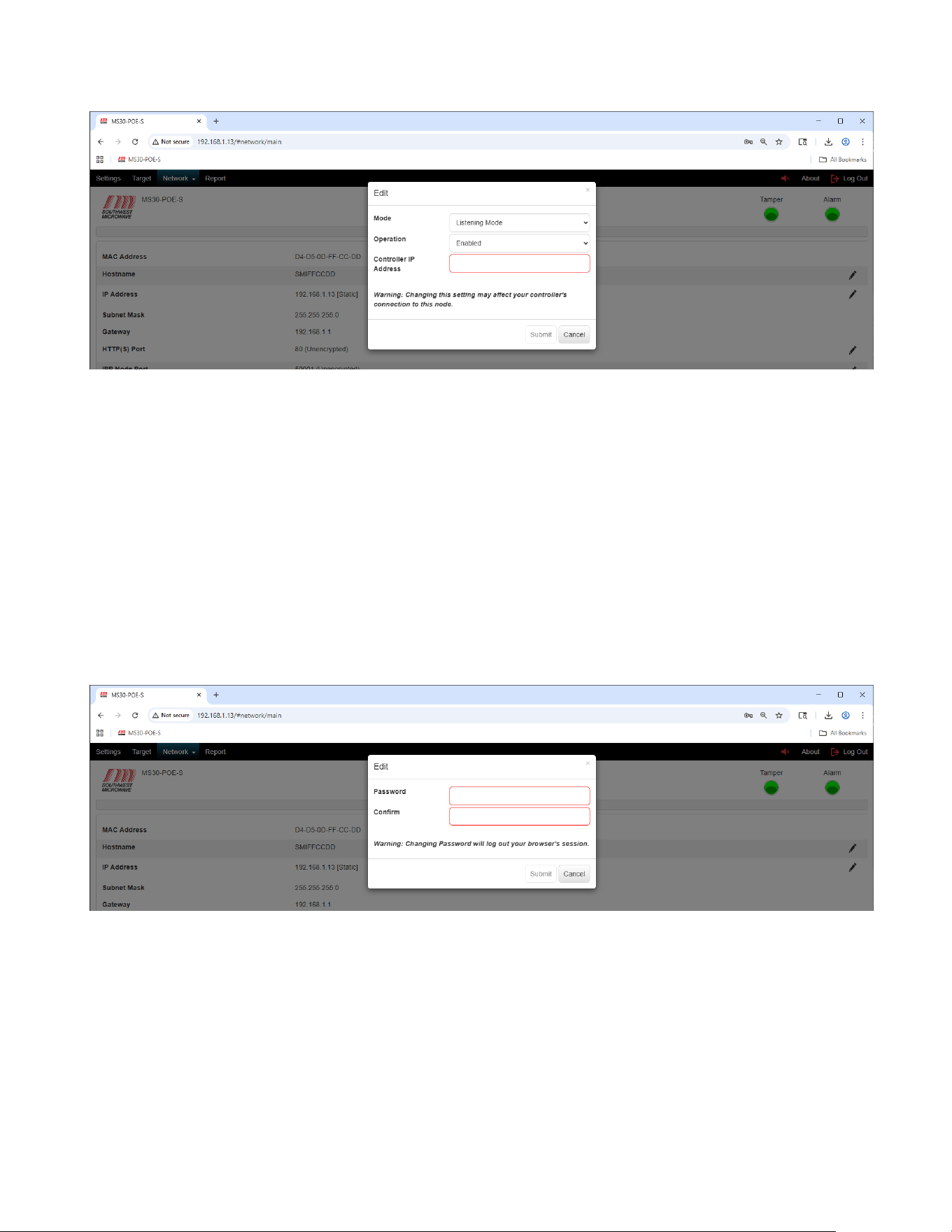
11.7 Password
To edit the “Password” select the pencil icon on the right of the screen to open the “Edit Password” dialog box as
shown in Figure 11.11. This Edit box will allow configuring a new password for the motion sensor.
The password must be a minimum of eight (8) characters and include one upper case letter (A-Z), one lower case
letter (a-z), one digit (0-9) and one special character (!#$%). The maximum length is sixteen (16) characters.
Selecting the field will display these requirements.
Enter a new password in the “Password” field. Enter the password again in the “Confirm” field. Select the
“Submit” button to update the changes. Select the “Cancel” button to end the task.
A warning will be displayed stating: “Warning: Changing Password will log out your browser session”.
Figure 11.11 – Edit Password
11.8 Geolocation
To edit the “Geolocation” coordinates select the pencil icon on the right of the screen to open the “Edit
Geolocation” dialog box as shown in Figure 11.12. This Edit box will allow manual entry for Latitude and
Longitude (in degrees) assignment and Altitude (in meters) assignment for the Model MS30-POE-S.
Enter the latitude, longitude, and altitude in (decimal degrees and meters) and select the “Submit” button to
update the changes. Select the “Cancel” button to end the task. The “Use My Location” button requires an
encrypted connection. This will only be active when the HTTP security mode has been engaged.
Model MS30-POE-S Manual
36 Version 0
Figure 11.12 – Edit Geolocation
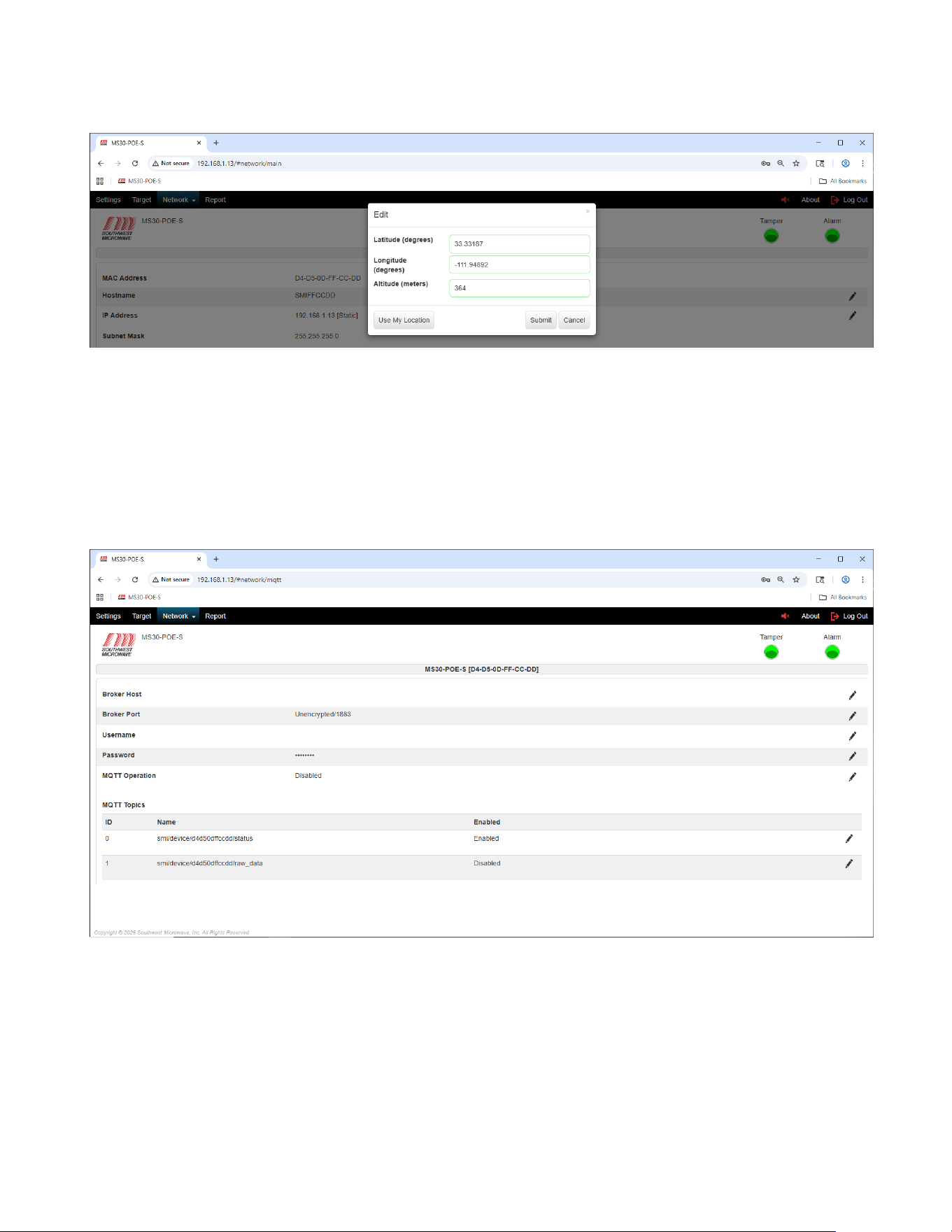
11.9 MQTT
To edit and enable “MQTT” (Message Queuing Telemetry Transport) settings select the MQTT tab under the
network tab to open the MQTT configuration screen as shown in Figure 11.13. This screen box will be used for
configuring the Broker Host, Broker Port, Username, Password, MQTT Operation and MQTT Topic for Model
MS30-POE-S.
Figure 11.13 – MQTT
A broker host must be installed and the IP address entered to the Broker Host field.
The Broker Port can be changed (default is 1883) and can also be set for encryption.
A Username can be added if required.
The MQTT Operation should be Enabled and the MQTT Topics ID 0 should be enabled.
Model MS30-POE-S Manual
37 Version 0
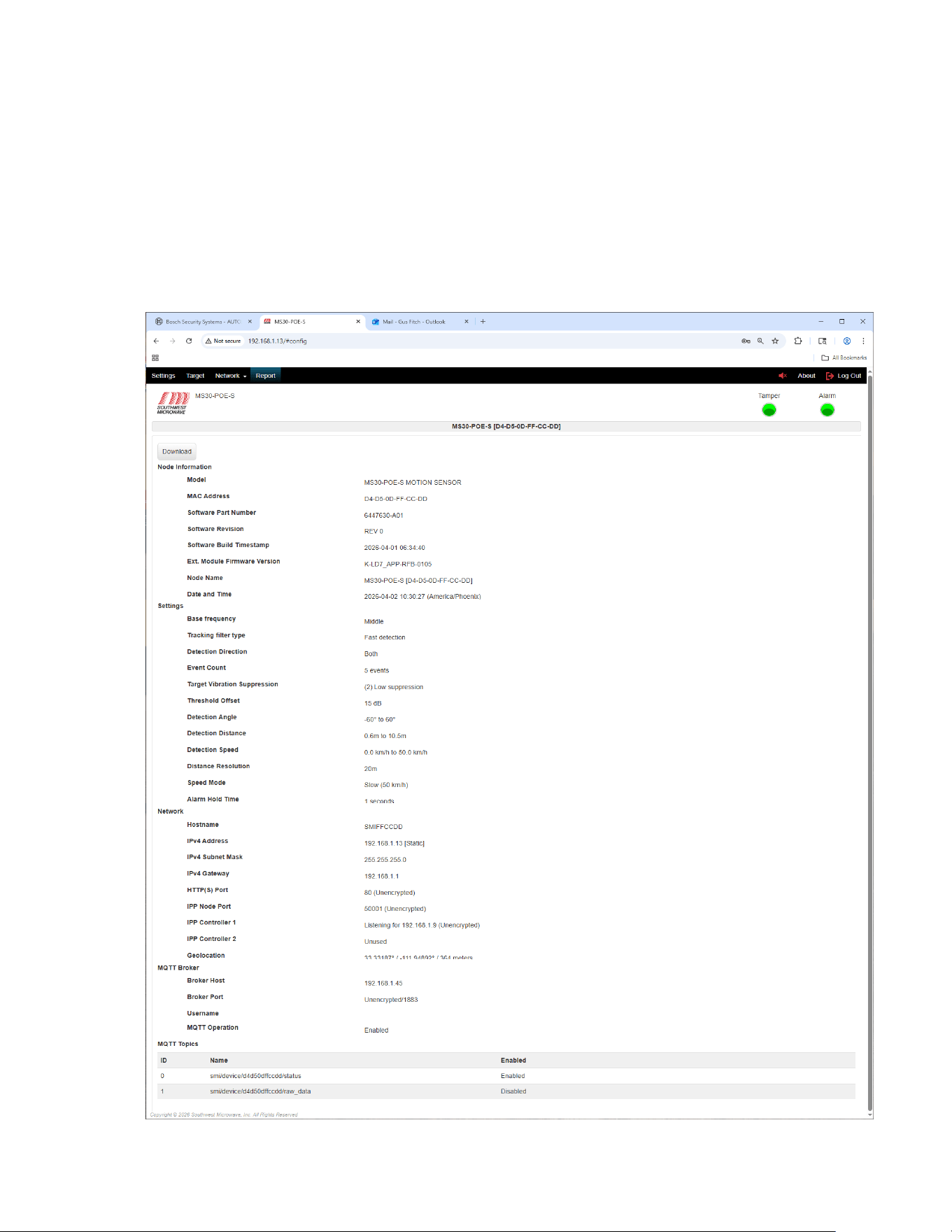
12.0 Report
Selecting the “Report” tab will open a report of the Model MS30-POE-S node information, settings, network
settings, and MQTT Broker and topics as shown in Figure 12.1.
The report can be downloaded by selecting the “Download” button. The file will be saved to the “Downloads”
folder on the PC as an HTML document as MODEL-MS30-POE-S-MAC ADDRESS-CONFIG-REPORT-
DATE-TIME. In example: MODEL-MS30-POE-S-94-54-C5-F7-00-83-CONFIG-REPORT-2026-03-18-08-31-
21.
Figure 12.1 – Report
Model MS30-POE-S Manual
38 Version 0
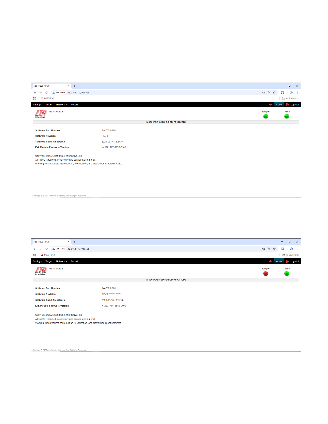
13.0 Transceiver About and Upgrade Firmware Screen
Selecting the “About” button will open information on Software Number, Software Version, Software Build, and
copyright about the Model MS30-POE-S as shown in Figure 13.1.
Figure 13.1 – About Screen
If the radome cover of the transceiver has been removed activating the tamper circuit, the “Upgrade Firmware”
option will be displayed next to the Software Version field as shown in Figure 13.2.
Figure 13.2 – Select Upgrade Firmware
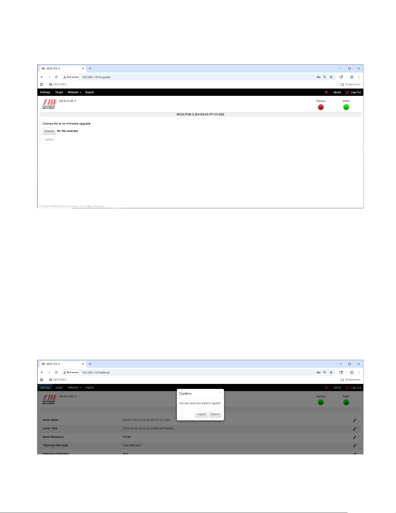
Selecting “Upgrade Firmware” field (in red) will open the “Upgrade Firmware” screen as shown in Figure 13.3.
Model MS30-POE-S Manual
39 Version 0
Figure 13.3 – Upgrade Firmware
If there has been an upgrade to the firmware, Southwest Microwave will email the update in a *.bin file format. In
example: 6447630-A01_MS30_REV.0_20260316_1354.bin. Copy the file to a place on the PC or flash drive so it
can easily be accessed. Select the “Browse” button to find the location where the file was saved. When selected, it
will be displayed next to the Browse button, and the Upload button will become active.
Select the “Upload” button. A “Confirm” dialog box will open asking to upload the selected file with the file
name listed, an “Enter Password” field and a “Upload” and “Cancel” button. Enter password and select “Upload”.
Once complete a “Success” dialog box will open and then return to the Login screen. Cancel will end the task.
14.0 Transceiver Log-Out Screen
Selecting the “Log Out” button will open a dialog box asking, “Are you sure you want to log out?” as shown in
Figure 14.1. Select the “Logout” button to exit the program. Select the “Cancel” button to end the task.
Figure 14.1 – Logout Screen
Model MS30-POE-S Manual
40 Version 0
15.0 SSL-Encryption and Certificates
The Model MS30-POE-S has the option to be set to a secure HTTPS connection for the browser. A CA certificate
and key must be installed. Max size is 2k. Recent updates in most major browsers (Chrome, Edge, Firefox) no
longer treat self-signed certificates as secure.
As such, please review Technical Note 1002 before proceeding with any of the following steps.
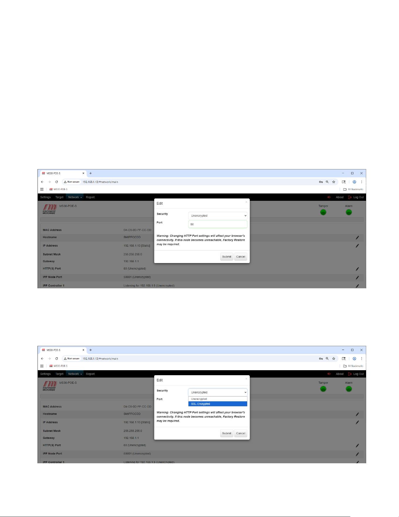
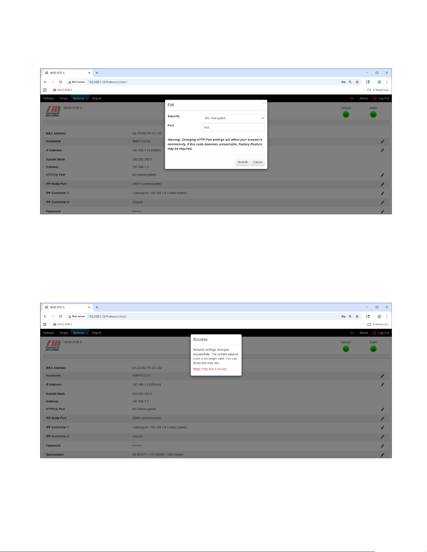
15.1 Activating HTTPS Encryption
To activate the HTTPS browser encryption for MS30-POE-S, select the pencil icon on the right of the screen to
open the “Edit HTTP(S)” dialog box as shown in Figure 15.1.
Figure 15.1 – Edit HTTP(S)
To change the security of the “HTTP(S) Port” to Encrypted select the “Security” pull down menu to open the
SSL-Encrypted setting as shown in Figure 15.2. Selecting the “SSL-Encrypted” line will change the port to 443 as
shown in Figure 15.3.
Figure 15.2 – SSL-Encrypted
Model MS30-POE-S Manual
41 Version 0
Figure 15.3 – SSL-Encrypted Selected
A warning will be displayed stating: “Warning: Changing HTTP Port settings will affect your browsers
connectivity. If the node becomes unreachable, Factory Restore may be required”.
Select the “Submit” button to update the change. The “Cancel” button will end the task. Once the submit button
has been selected a dialog box will open stating “Success. Network settings changed successfully. The current
session route is no longer valid. You can follow this new link. https//192.168.1.12:443.” as shown in Figure 15.4.
Figure 15.4 – Network Setting Changed Successfully
Click on the address in Figure 15.4 to open the https connection.
Model MS30-POE-S Manual
42 Version 0
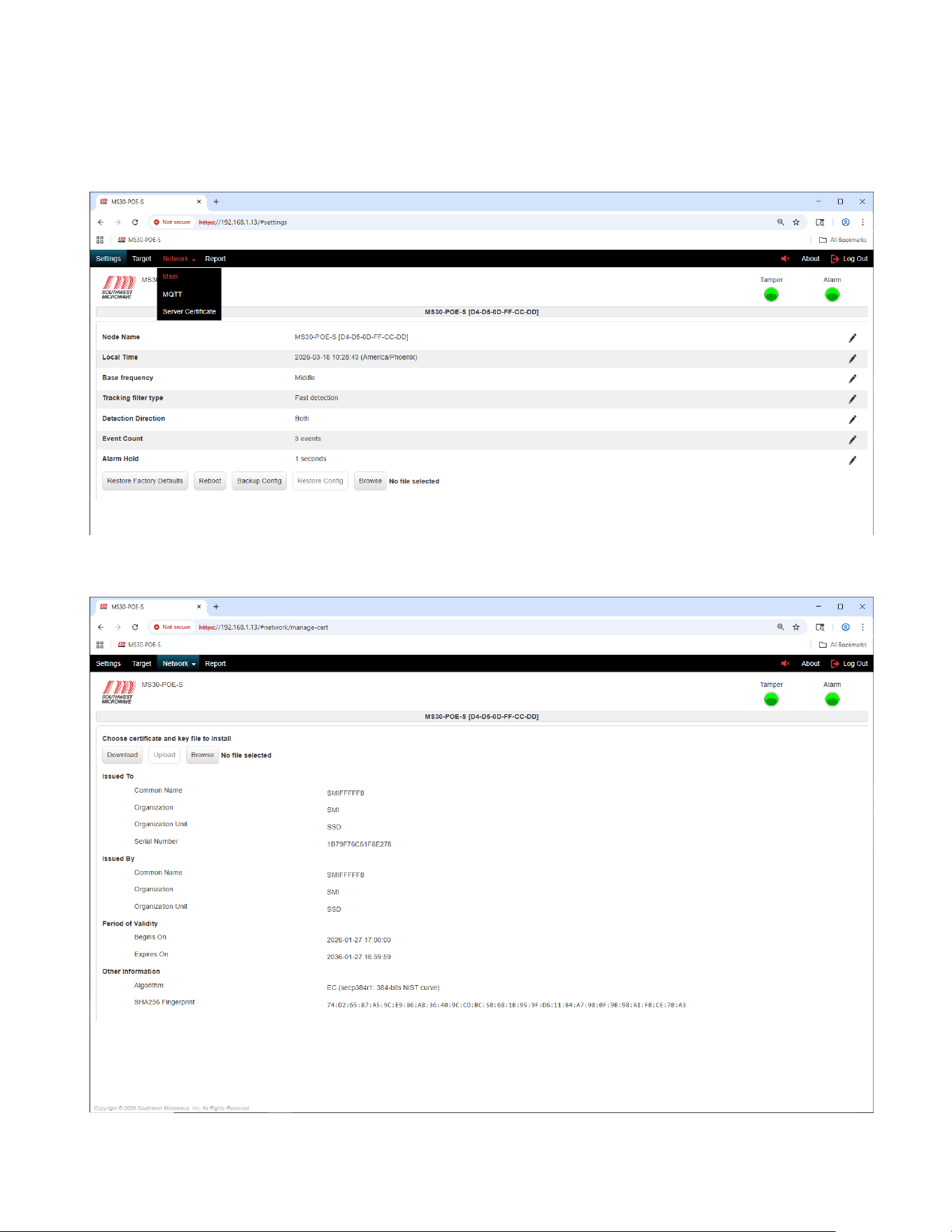
Once logged back in, select the “Network” tab to open the “Server Certificate” tab as shown in Figure 15.5. Select
the Server Certificate tab to open the certificates settings as shown in Figure 15.6.
Figure 15.5 – Server Certificate Tab
Figure 15.6 – Server Certificate Information
Model MS30-POE-S Manual
43 Version 0
The information and options available on this page are:
➢ Download: Button to download a certificate and key on the computer.
➢ Upload: Button to upload a third-party certificate into the Model MS30-POE-S transceiver.
➢ Browse: Button to search for a certificate.
➢ Issued To: Common name, Organization, Organization Unit and Serial Number of the current certificate.
➢ Issued By: Common name, Organization, and Organization Unit of the current certificate.
➢ Period of Validity: Begins On and Expires On dates and time.
➢ Other Information: Algorithm and SHA256 Fingerprint.
The “Browse” button can be used to find a certificate to “Upload” to the MS30-POE-S. When a certificate is
found the “Upload” button will become available.
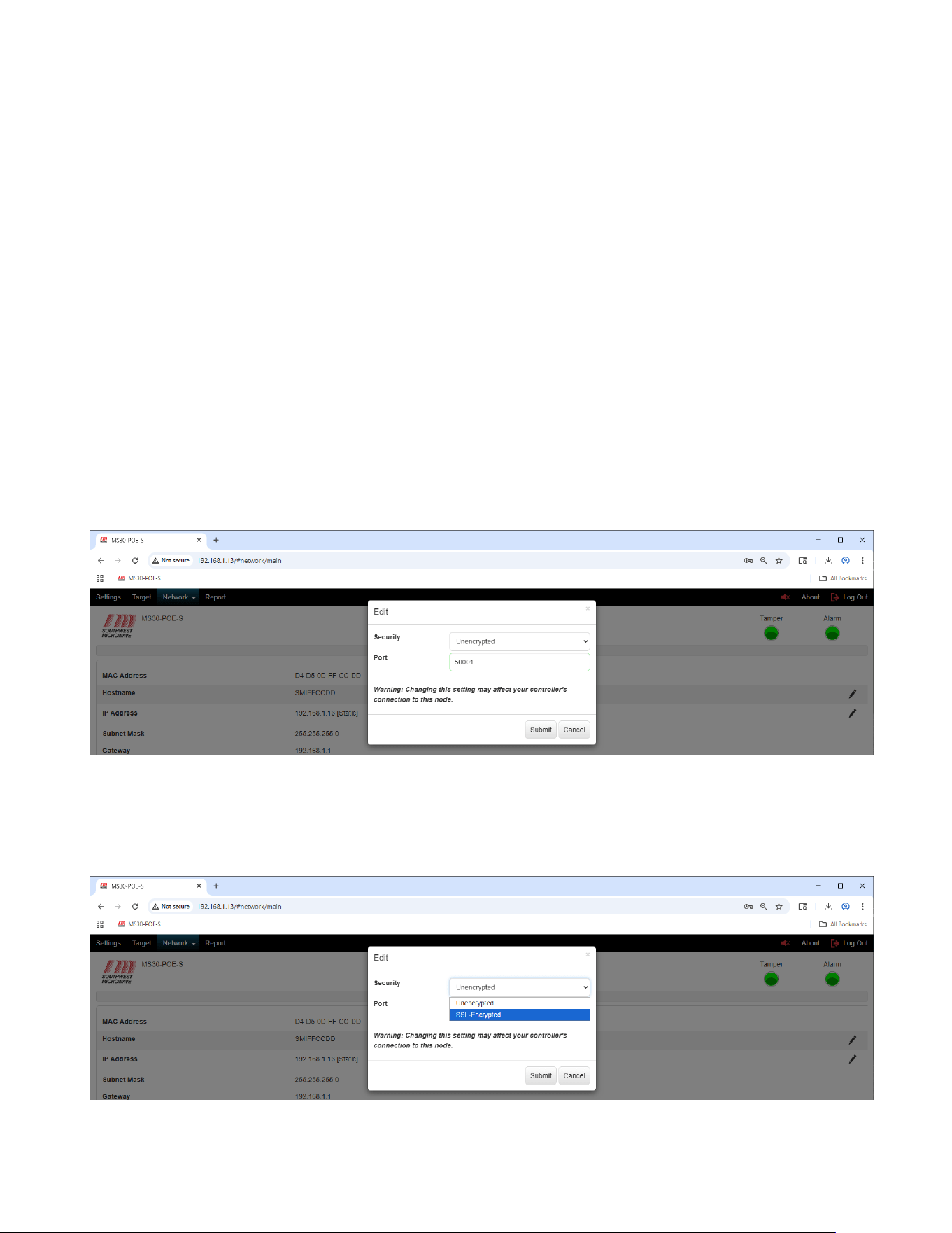
15.2 Activating IPP Node Port Encryption
To activate the IPP Node Port encryption for Model MS30-POE-S select the pencil icon on the right of the screen
to open the “Edit IPP Node Port” dialog box as shown in Figure 15.7. This applies to the transmitter and receiver.
Figure 15.7 – IPP Node Port
To enable the SSL-Encryption, select the “SSL-Encryption” from the Security pull down menu as shown in
Figure 15.8. If the IPP Controller port is active in “Listening” mode it will now show it is SSL-Encrypted.
Figure 15.17 – IPP Node Port Encryption

Model MS30-POE-S Manual
44 Version 0
15.3 Certificate Management Notes
15.3.1 Server Certificate Update
Requirements for a certificate to be uploaded:
a. Maximum size must not exceed 16Kbytes.
b. Must be PEM format: the PEM format is the most common format that Certificate Authorities
issue certificates in. PEM certificates usually have extensions such as .pem, .crt, and .cer. They
are Base64 encoded ASCII files and contain "-----BEGIN CERTIFICATE-----" and "-----END
CERTIFICATE-----" statements.
c. Must contain the private key used to generate the certificate.
d. The algorithm for the private key must be either RSA or EC:
i. EC: only two elliptic curves 256-bits NIST curve (secp256r1), 384-bits NIST curve
(secp384r1) are supported based on supported elliptic curves by browsers.
1. Chrome: tls_grease_6a6a, x25519, secp256r1, secp384r1
2. FireFox: x25519, secp256r1, secp384r1, secp521r1, ffdhe2048, ffdhe3072
3. IE: secp256r1, secp384r1
ii. RSA, key size 1024, 2048, or 4096. The larger the key size, the slower the performance.
e. The private key can be unencrypted or encrypted with AES or 3DES. To successfully upload a
certificate with encrypted key, the password used for encryption must be provided for decryption.
Please see the Appendix for examples of valid certificate files.
15.3.2 Server Certificate Download
1. Server certificate can be downloaded by going to Network->Server Certificate, click on Download button.
2. The downloaded certificate only contains the Certificate; the private key is not included. It cannot be
uploaded back to the device or other devices as the server certificate.
3. The downloaded certificate can be installed to the trusted Root CA store or uploaded to a device as a
trusted client CA.
16.0 Software Setup and Testing
This manual covers all the parameter settings required for system operation. The next two sections will cover the
software setup steps and testing.
The system should be installed using the Model MS30-POE-S Installation and Operation manual. All the wiring
should be correctly connected.
16.1 Software Setup
The following procedure is a step-by-step process to set up the Model MS30-POE-S motion sensor. Start by
connecting to the transceiver with a web browser using the default IP address of 192.168.1.13.

Model MS30-POE-S Manual
45 Version 0
1. Select “Restore Factory Defaults” from the Settings tab (Section 9.8).
2. Set the “Local Time” from the Settings tab (Section 9.2).
3. Set the “Node Name” from the Settings tab (Section 9.1).
4. Set a “Password” for this sensor from the “Network” tab (Section 11.7).
5. Set the network parameters from the “Network” tab to be used for this sensor (Section 11.2 to 11.9).
6. Set the “Alarm Hold” from the Settings tab for this sensor (Section 9.7).
7. Aim the sensor in the direction for detection. (Section 4.0).
8. Set the “Detection Angle and “Threshold Offset”. Walk test the unit. (Sections 10.3 and 10.4).
9. Once setup and testing are complete, select the Backup Config” from the Settings tab (Section 9.10).
10. Select the “Reports” tab (Section 12.0).
16.2 Testing
After steps 1 through 10 have been completed, the sensor is now ready for functional testing. The functional
testing is based on the user’s requirements. Typically, this would be walking, running, jumping and crawling
intrusion attempts to generate alarms. The testing person should weigh at least 77 pounds (35 kilograms). The IST
should be used to observe the testing. The Sonalert and the IST can be used while testing.
Adjust detection parameters by aiming/angling the unit and having a person walk towards the unit to set the range.
Use the IST to set the Threshold Offset until site requirements are obtained. Adjust the Threshold Offset to
optimize the sensor performance to meet detection requirements at the lowest setting possible.
Monitor the system for at least a week for nuisance and false alarm activity and make any needed adjustments.
17.0 Preventive Maintenance
Model MS30-POE-S requires no calibration other than alignment, Event Duration and sensitivity adjustment
during installation. To maintain a trouble-free system the following is recommended:
1. Clean and wax the radomes every 3 to 6 months using a Windex type cleaner and standard automotive
wax. (At maximum security installations, where detection of prone crawling targets is required, waxing
once a month is recommended).
2. Keep the isolation area clean and free of tall grass, weeds, debris, washouts, and obstructions.
3. After initial installation, save the Report from the IST for reference.
4. If standby batteries are used, they should be functionally tested every three months.
5. A site inspection should be carried out every six months. The inspection should include verifying data
from Step 3, checking for physical damage (cracks, leaks, corrosion, etc.) checking for isolation zone
changes (washouts, materials placement, vegetation growth, loose fence fabric, etc.).

Model MS30-POE-S Manual
46 Version 0
18.0 Troubleshooting
Model MS30-POE-S is a sophisticated transceiver that utilizes very high impedance circuitry. Therefore, critical
circuits are factory aligned and tested, then packaged with shielded circuitry. The enclosed circuits are not field
repairable; however, adjustments (in the IST) are available externally so that performance may be measured, and
problems may be identified.
1.0 INSPECTION
Remove the radome (be sure to save the radome screws). Look for bad network connections, water ingress,
insects or blown fuses. DO NOT TOUCH THE ANTENNA.
Reviewing the technical manual making certain Model MS30-POE-S installed is set up in accordance with
Southwest Microwave Inc. instructions.
2.0 ELECTRICAL TEST
2.1 Input Power
Make sure the LEDs on the network port are illuminated.
2.2 Alignment
Make sure the unit is oriented and angled for the site-specific detection area.
2.5 Threshold Offset (Sensitivity)
Using the IST check and verify reading as discussed in Section 10.7. With no movement in the detection
pattern the Target should have little or no movement. Movement in the detection pattern (Doppler signal)
should cause an alarm to be generated whenever threshold is exceeded.
2.6 Tamper Switch
Install the radome. Be sure it is seated properly and secured tightly. Use IST software to check that
tamper switch(s) is actuated and cleared when the radome is replaced and removed.
19.0 Limited Warranty
SOUTHWEST MICROWAVE, INC., warrants each of its products to be free from defects in materials and
workmanship. The limit of liability under this warranty is to repair or replace any products or part thereof which
shall within three years after delivery to the original user be returned, shipping costs prepaid and insured, to
SOUTHWEST MICROWAVE, INC. at its plant in Tempe, Arizona, or authorized Warranty Service Company,
and which shall have been found to be defective upon examination by SOUTHWEST MICROWAVE, INC. or
authorized Warranty Service Company.
This warranty shall be limited to the repair or replacement of SOUTHWEST MICROWAVE, INC. products and
shall not extend to any incidental or consequential damages there from. Disassembly of any product by anyone
other than an authorized representative of SOUTHWEST MICROWAVE, INC. voids the obligations of
SOUTHWEST MICROWAVE, INC. to repair or replace any products so disassembled.

Model MS30-POE-S Manual
47 Version 0
Excluded from this warranty are fuses and batteries except to the extent that the original manufacturer warrants
such parts, and such warranty is marked on the product. Claim under warranty for fuses and batteries should be
made by the purchaser directly to the manufacturer.
Warranty returns must first be authorized by SOUTHWEST MICROWAVE, INC., or authorized Warranty
Service Company.
SOUTHWEST MICROWAVE, INC. reserves the right to make changes in design on any of its products without
incurring any obligation to make the same changes on units previously purchased.
This warranty is the extent of the obligations or liabilities assumed by SOUTHWEST MICROWAVE, INC. With
respect to its products and is in lieu of all other warranties, express or implied, including, but not limited to, any
warranty of merchantability or fitness. SOUTHWEST MICROWAVE, INC., shall not be liable for consequential
damages and its liability is expressly limited to the obligations expressed herein. SOUTHWEST MICROWAVE,
INC. Neither assumes nor authorizes any other person to assume for it any other warranty concerning its products.
20.0 Returning Equipment under Warranty
As per the provisions set forth in our Security Products warranty, any person desiring to return equipment to
SOUTHWEST MICROWAVE, INC. for any reason, must first contact SOUTHWEST MICROWAVE, INC. for
authorization of return.
An authorization number will be issued at the time of contact, and this number will appear on all correspondence,
invoices and credits pertaining to subject equipment.
ALL SOUTHWEST MICROWAVE; INC. sensors and power supplies are provided with a serial number at the
time of manufacture. In order to accurately and efficiently supply replacement parts, perform repair service, or
issue credit on equipment being returned to SOUTHWEST MICROWAVE, INC., it is essential that
SOUTHWEST MICROWAVE, INC., be advised of the serial number of the equipment prior to authorization for
return. This notification may be made by telephone or by mail.
21.0 Returning Equipment for Non-Warranty Repair
Return of equipment out of warranty must first be authorized by SOUTHWEST MICROWAVE, INC., at which
time a return authorization number will be issued. The returned equipment must be accompanied by an evaluation
repair purchase order. Returned equipment will be examined and customers advised of the cost of repair or
replacement.
22.0 Replacement Parts
To order a replacement or module, specify the complete part number and serial number and address the order or
contact us at:
SOUTHWEST MICROWAVE, INC.
9055 South McKemy Street
Tempe, Arizona 85284-2946
TEL: (480) 783-0201
FAX: (480) 783-0401
www.southwestmicrowave.com

Model MS30-POE-S Manual
48 Version 0