Technical Support and E-Warranty Certificate
www.vevor.com/support
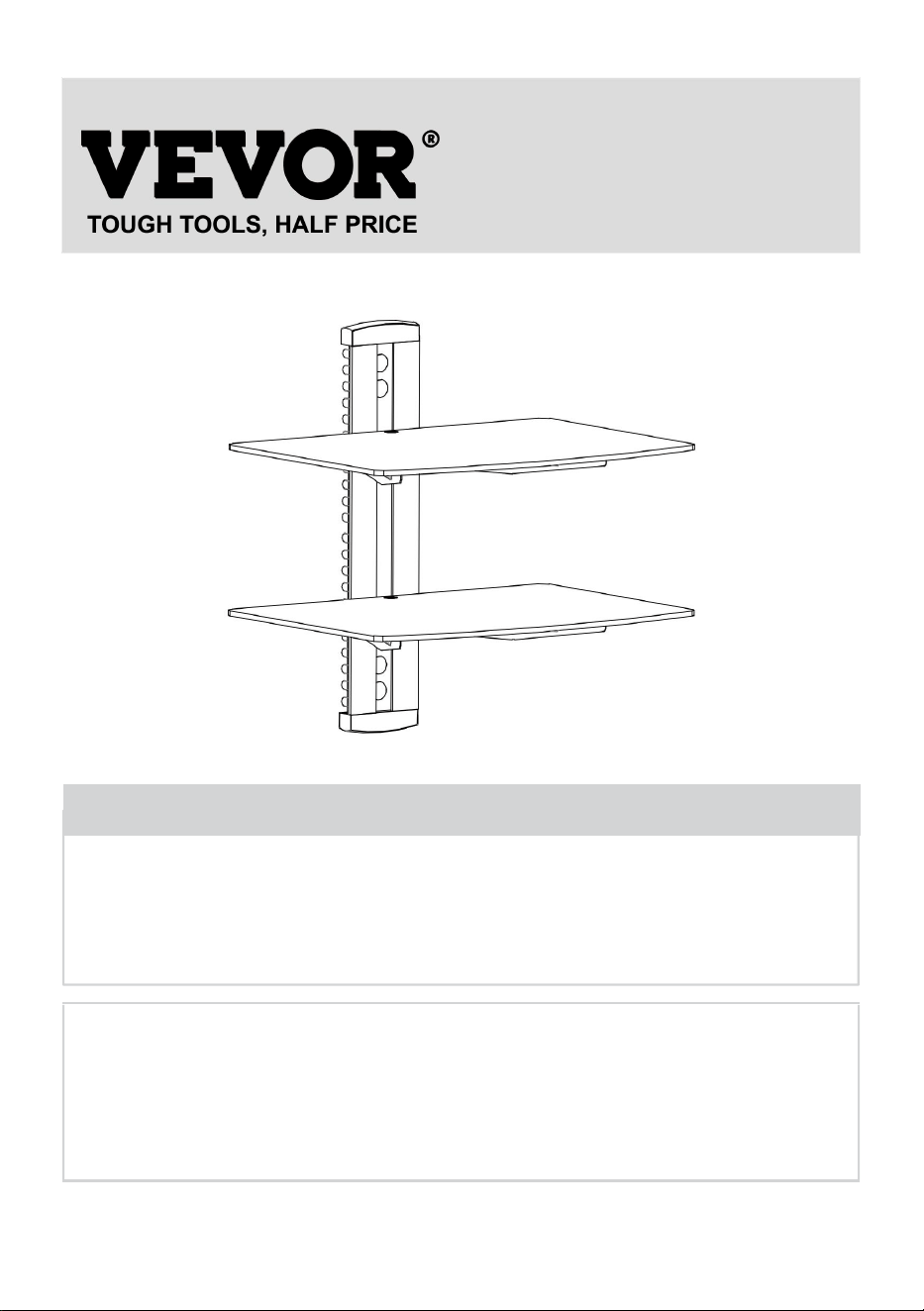
AUDIO COMPONENT STAND
USER MANUAL
MODEL NO.: CS202
We continue to be committed to provide you tools with competitive price.
"Save Half", "Half Price" or any other similar expressions used by us only represents an
estimate of savings you might benefit from buying certain tools with us compared to the major
top brands and does not necessarily mean to cover all categories of tools offered by us. You
are kindly reminded to verify carefully when you are placing an order with us if you are
actually saving half in comparison with the top major brands.
- 1 -
MODEL: CS202
Have product questions? Need technical support? Please feel free to
contact us:
Technical Support and E-Warranty Certificate
www.vevor.com/support
NEED HELP? CONTACT US!
This is the original instruction, please read all manual instructions
carefully before operating. VEVOR reserves a clear interpretation of our
user manual. The appearance of the product shall be subject to the
product you received. Please forgive us that we won't inform you again if
there are any technology or software updates on our product.
Audio Component Stand

- 2 -
WARNING:
Please read this manual carefully before using the product. Failure to
do so may result in serious injury.
ASSEMBLY PRECAUTIONS
Do not install the product until you have read and understood the
instructions and warnings provided in this installation sheet. If you
have any questions regarding any of the instructions or warnings,
please contact your local distributor.
Please refer to the installation guide for recommended distances from
the wall to avoid the risk of property damage.
This product should only be installed by someone with good
mechanical aptitude, experience in basic construction, and a full
understanding of the installation process.
Make sure that the supporting surface will safely support the combined
load of the equipment and all attached hardware and components.
If mounting to wood wall studs, make sure that mounting screws are
anchored into the center of the studs. Use of an “edge to edge” stud
finder is highly recommended.
Always use an assistant or mechanical lifting equipment to safely lift
and position equipment.
Tighten screws firmly, but do not overtighten. Over tightening can
damage the items, greatly reducing their holding power.
This product intended for indoor use only. Using this product outdoors
could lead to product failure and personal injury.
Never exceed the maximum load capacity.
SAVE THE INSTRUCTION

- 3 -
USE PRECAUTIONS
TO PREVENT SERIOUS INJURY AND DEATH FROM TIPPING:
1. This product is not a toy. Keep children away from this item.
2. Do not exceed weight capacities before moving.
3. Use only on a flat, hard and smooth surface capable of safely
supporting a fully loaded Audio Component Stand.
4. Use as intended only. Inspect before every use and do not use if parts
are loose or damaged.
TECHNICAL SPECIFICATIONS
Model
CS202
Product Dimensions
(LxWxH)(mm)
425*240*320
Packing
Size(LxWxH)(mm)
410*298*55
Net Weight(kg)
About 2.6
Gross Weight(kg)
About 3
*Products such as specifications, appearance, and design are
subject to modification without prior notice.
- 4 -
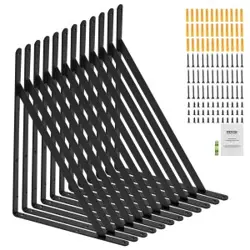
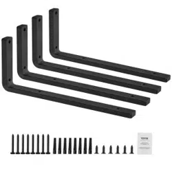
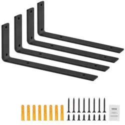
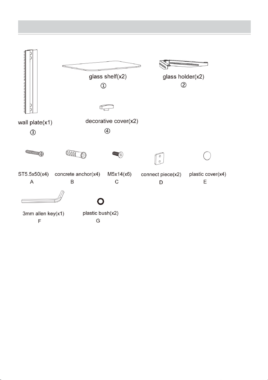
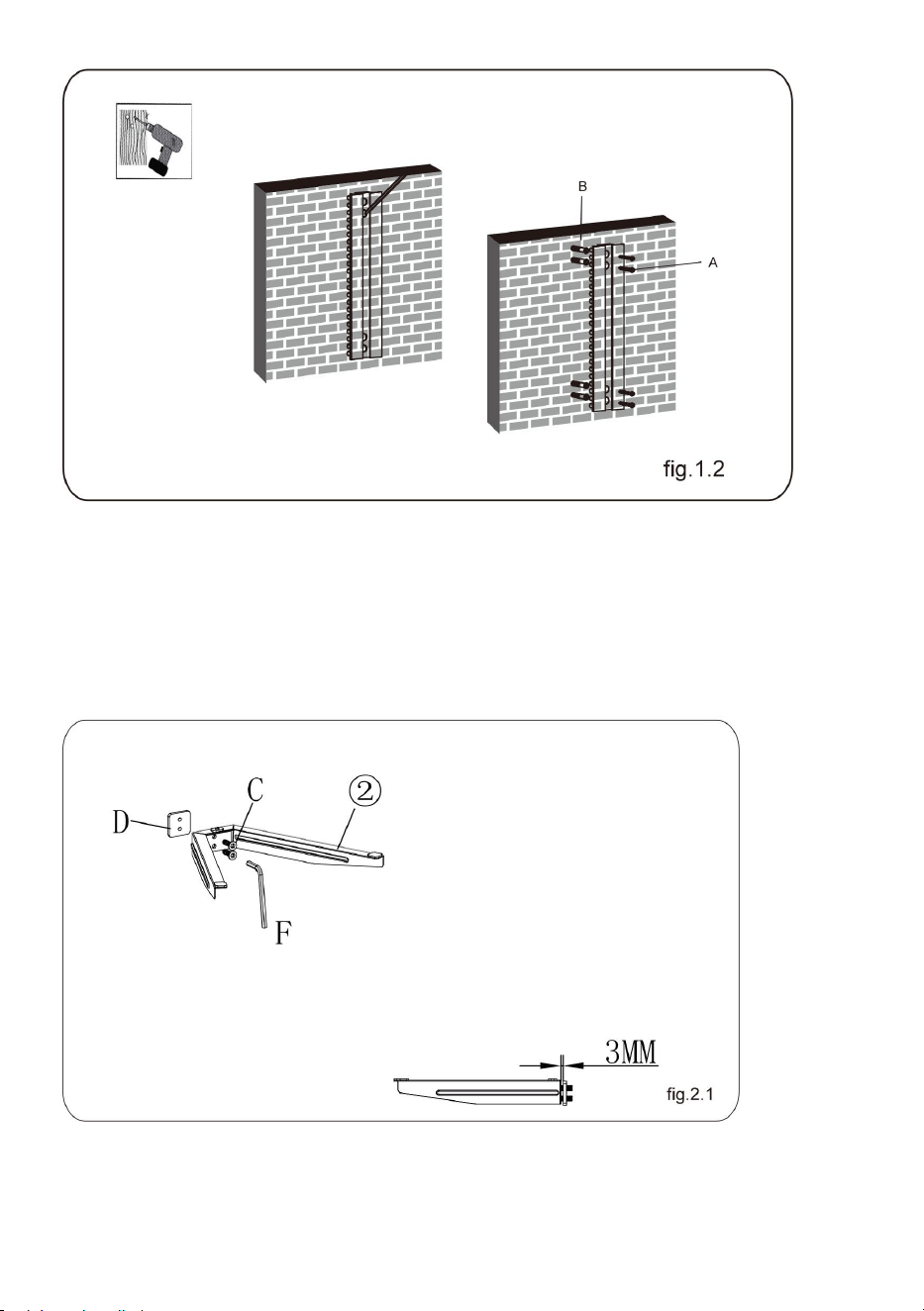
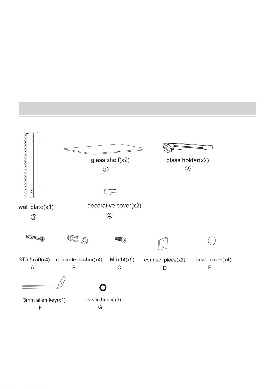
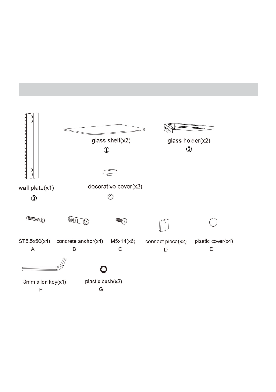
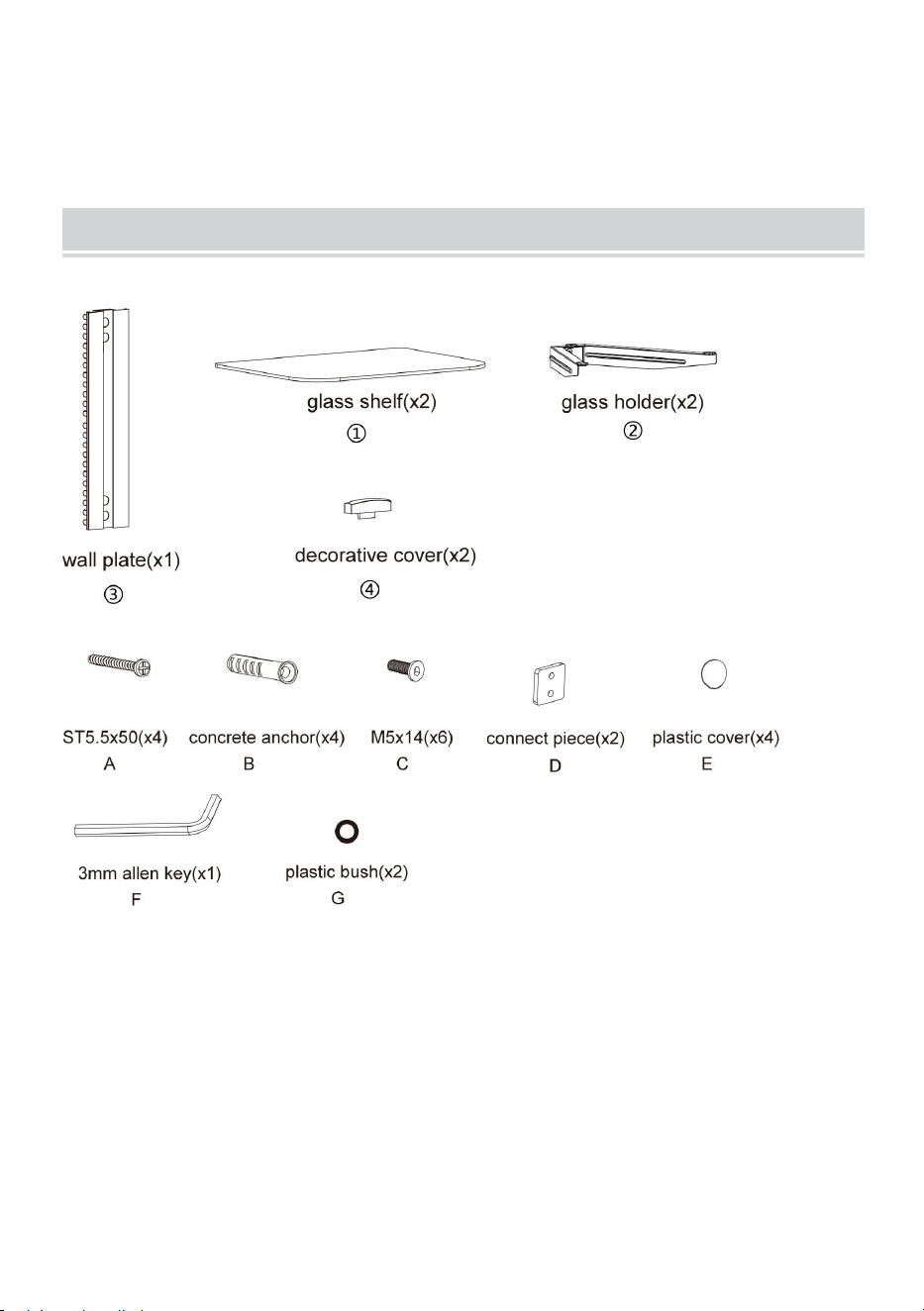
PACKAGE CONTENTS
Tools required
Phillips Head Screw Driver (Length: 200mm (Excluding the
Handle) )
Electric Drill and 8mm Masonry Bit for Concrete Wall Installation
Marking Pen
Hammer
- 5 -
ASSEMBLY STEPS
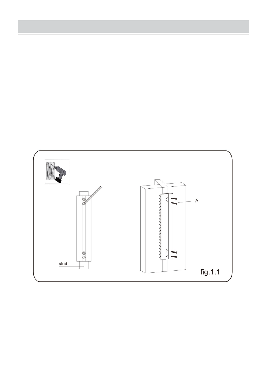
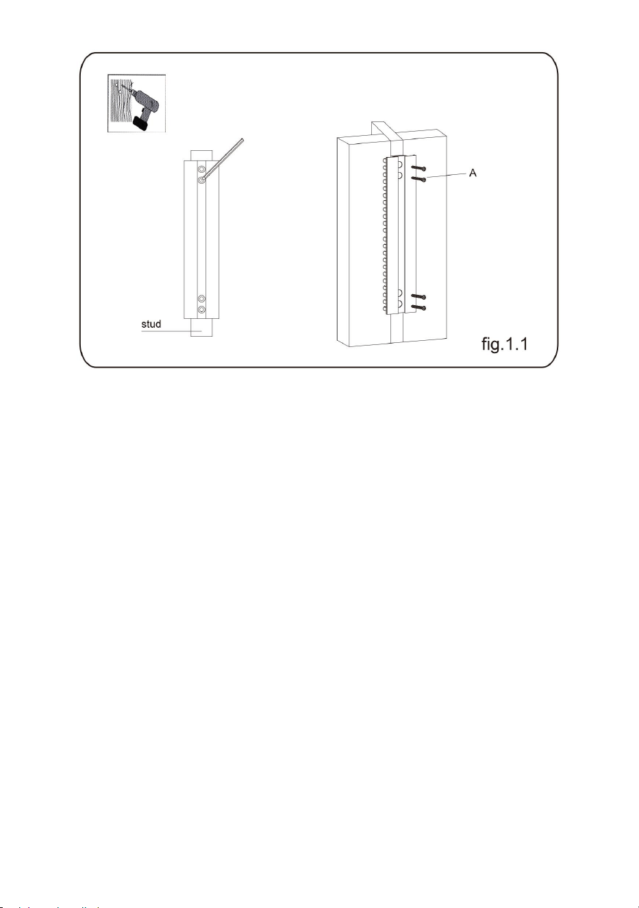
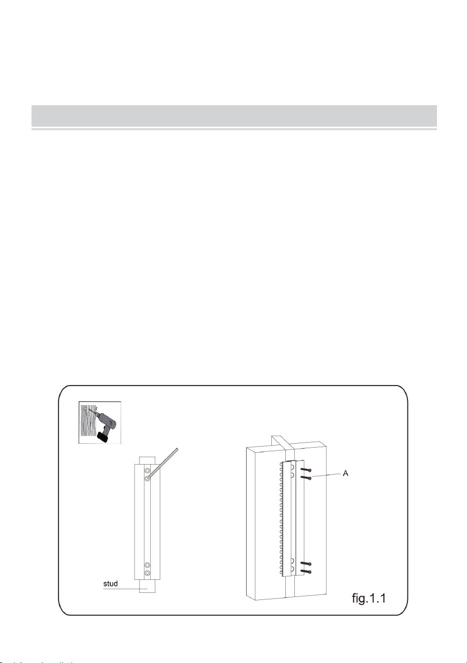
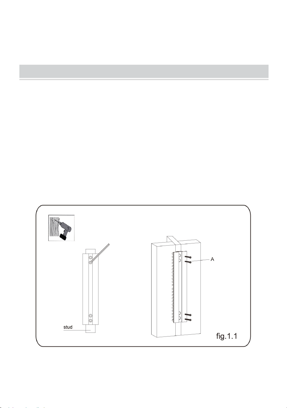
STEP1-a: WOOD STUD WALL MOUNTING:
● Use a stud finder to locate the edges of the studs. It is highly
recommended to use an edge-to-edge stud finder. Draw a vertical
line down the center of each stud based on their edges.
● Place wall plate on wall as a template and mark the center
of the four mounting holes. Make sure that the mounting holes are
on the centerline of stud.
● Drill four 1/8” (3mm) diameter holes 1.2” (30mm) deep. Secure it
using four screws(A), make sure that the wall plate is level as shown
in fig.1.1.
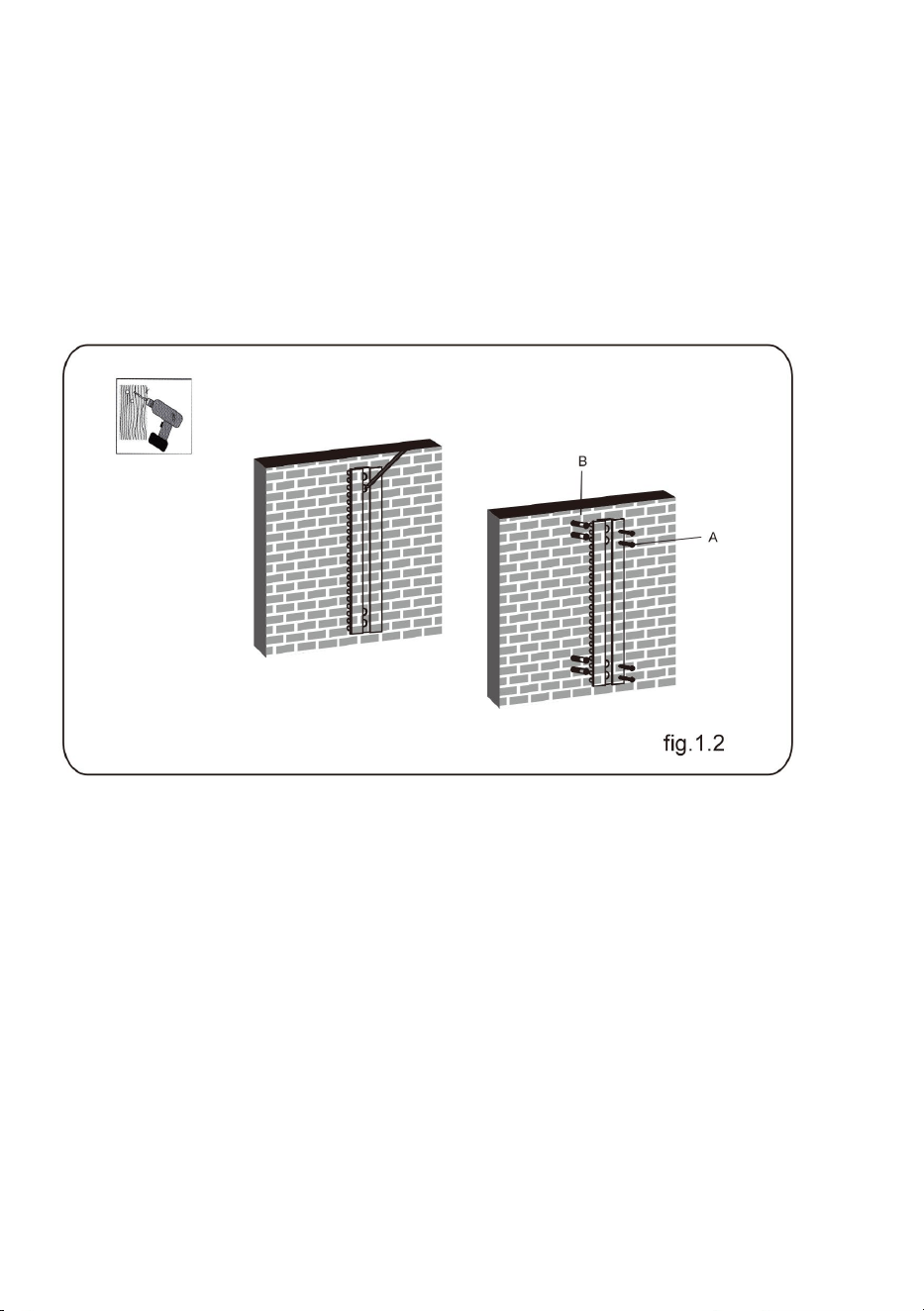
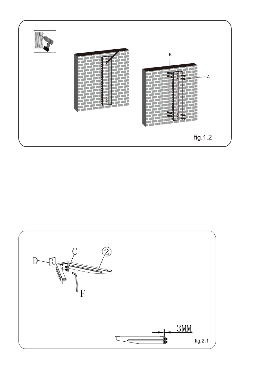
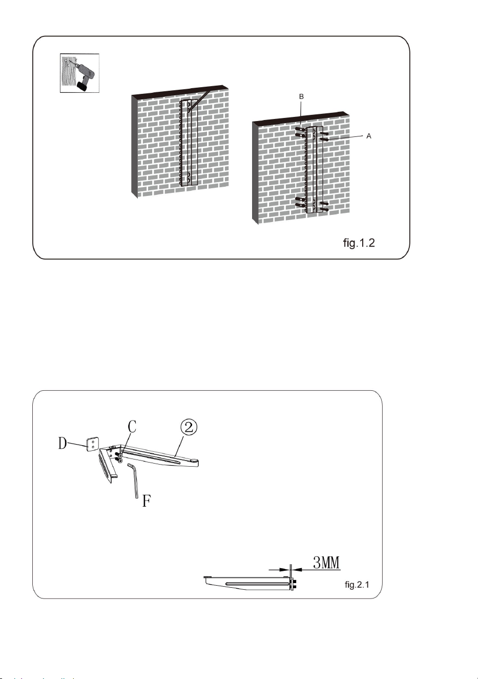
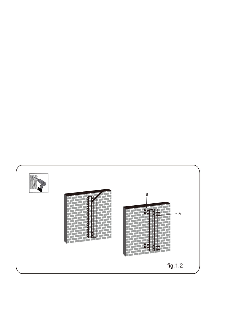
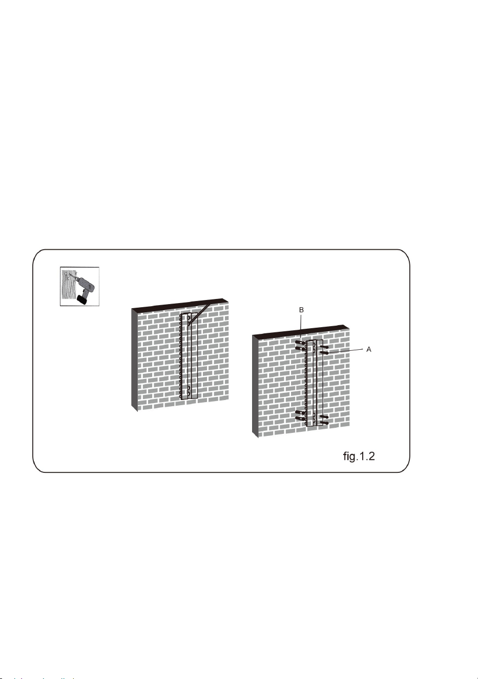
STEP1-b: SOLID BRICK AND CONCRETE BLOCK
- 6 -
MOUNTING:
● Use the wall plate as a template to mark locations of four holes on
the wall as shown in fig.1.2.
● Pre-drill these holes with a 8mm masonry bit , ensuring a depth of
at least 50mm. Insert a Concrete Anchor(B) into each of these holes.
● Attach the wall plate to the wall using four screws(A), make sure
that the wall plate is level as shown in fig.1.2.
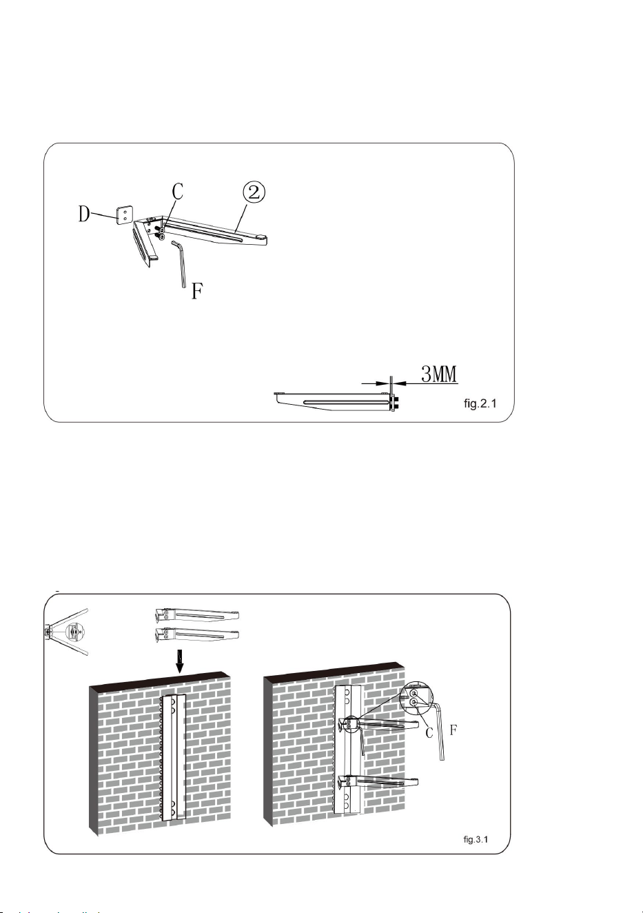
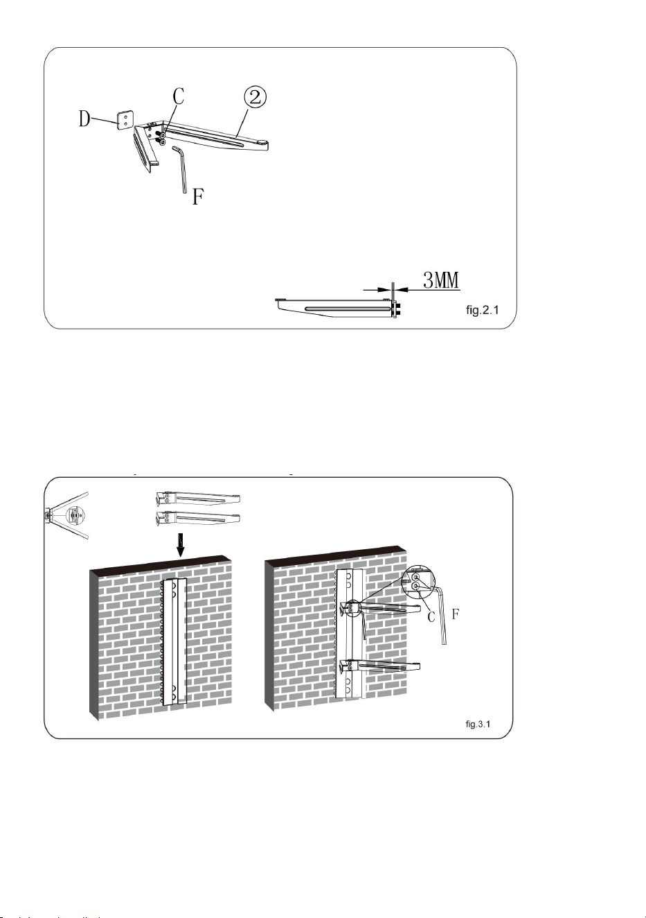
STEP2: ASSEMBLING THE GLASS HOLDER
● Attach the connect piece to the glass holder using two screws,
leaving a 3mm space as shown in fig.2.1.
● Repeat the same method to assemble the other glass holder.

- 7 -
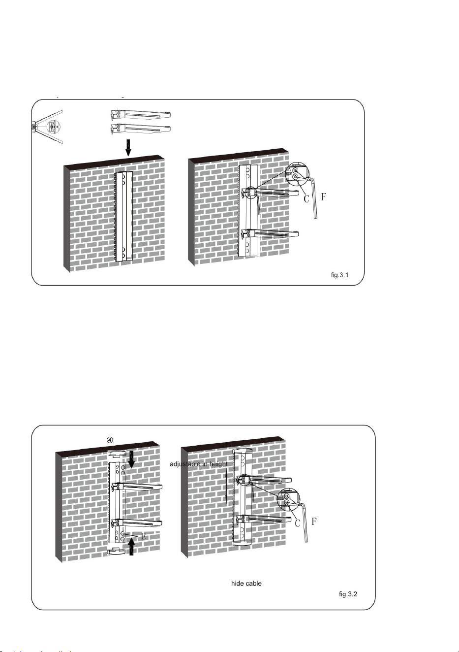
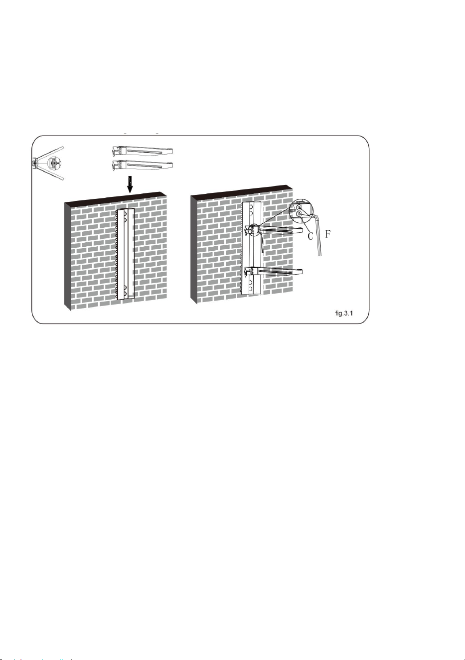
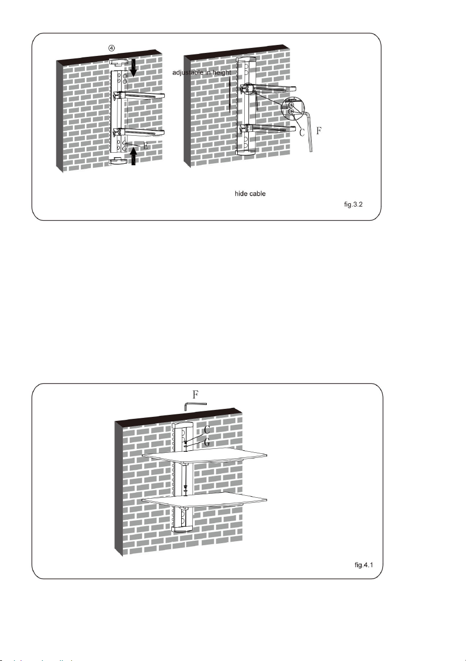
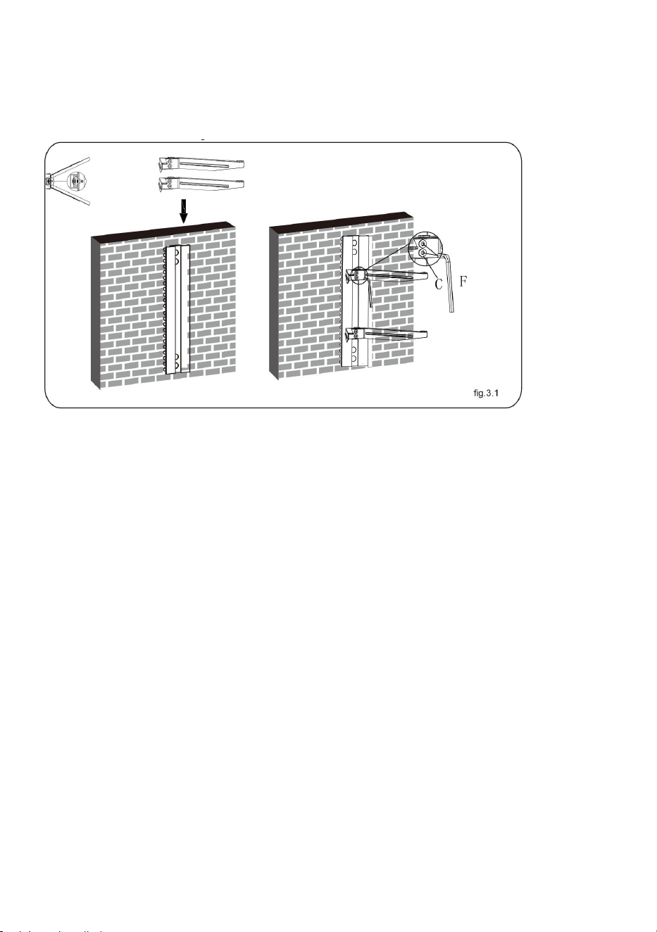
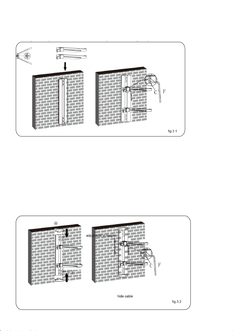
STEP3: INSTALLING THE GLASS HOLDER
● Insert the two glass holders into the wall plate along the wall plate
rail at the desired height respectively, and then tighten four screws
with a 3mm Allen key as shown in fig.3.1.
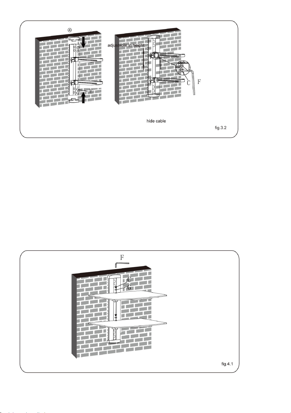
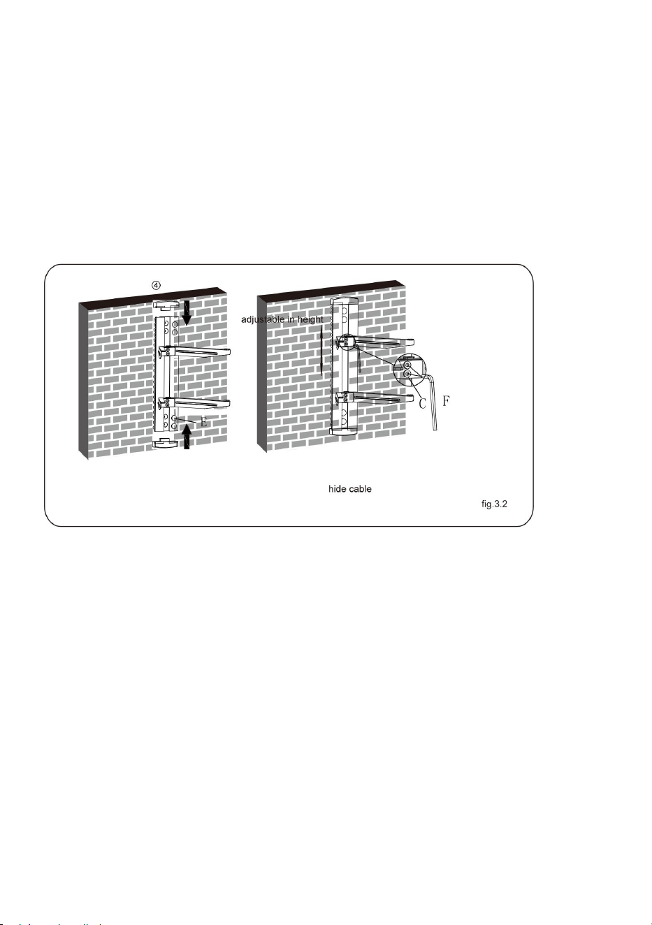
● Insert two decorative covers to the top and bottom of wall plate
respectively and install four plastic covers as shown in fig.3.2.
● You can adjust the height of the glass holders as needed. Loosen
the screws with a 3mm Allen key(but not remove) to adjust the glass
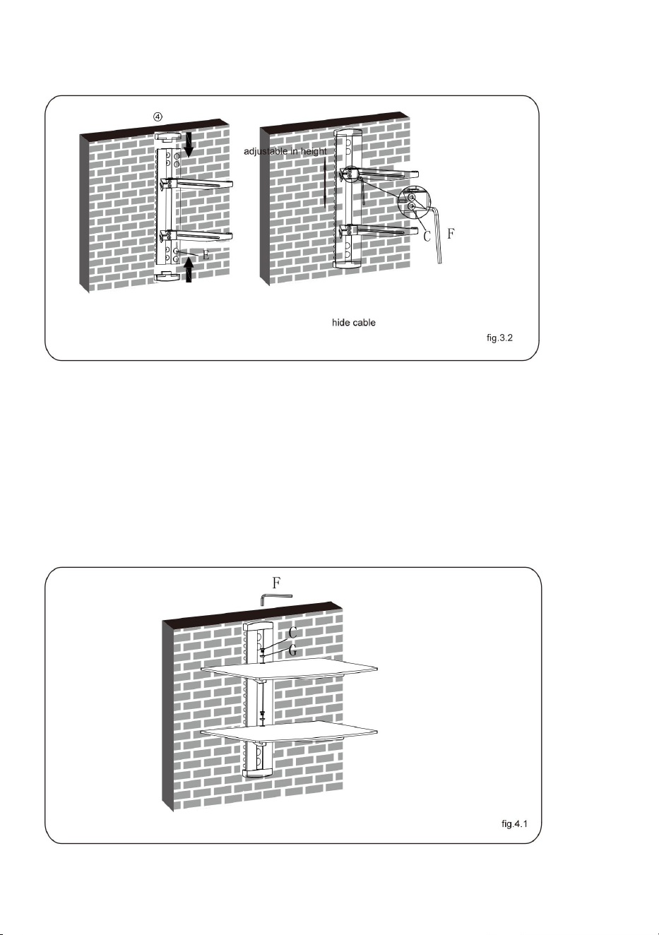
- 8 -
holders at the desired height and then tighten screws with a 3mm
Allen key as shown in fig.3.2.
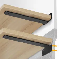
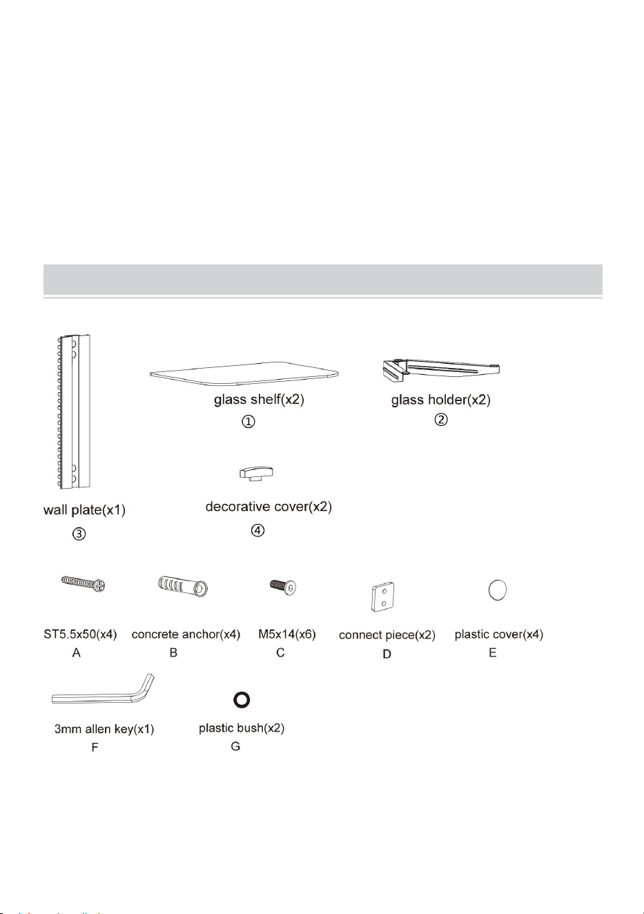
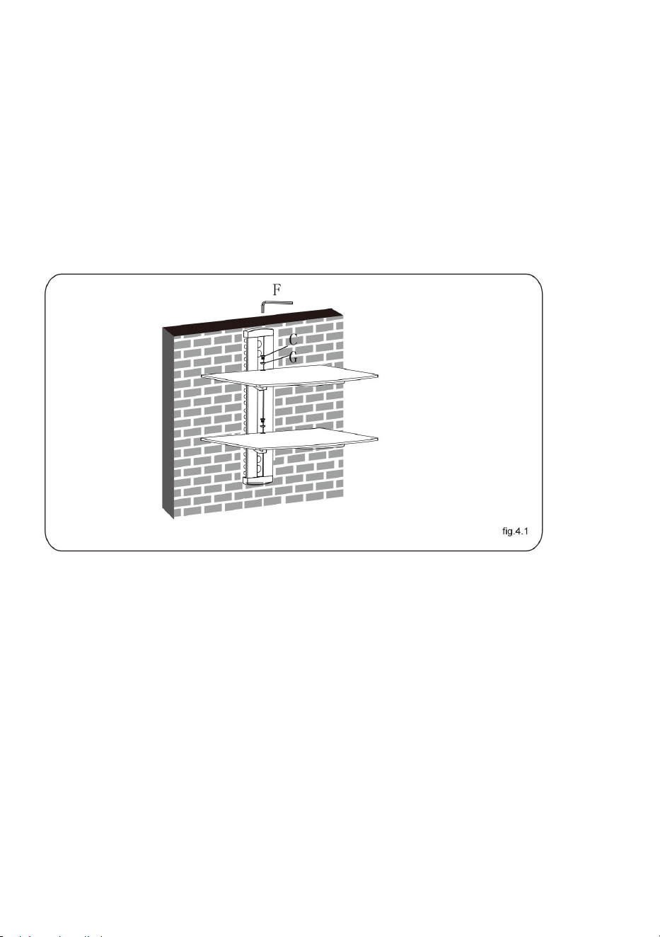
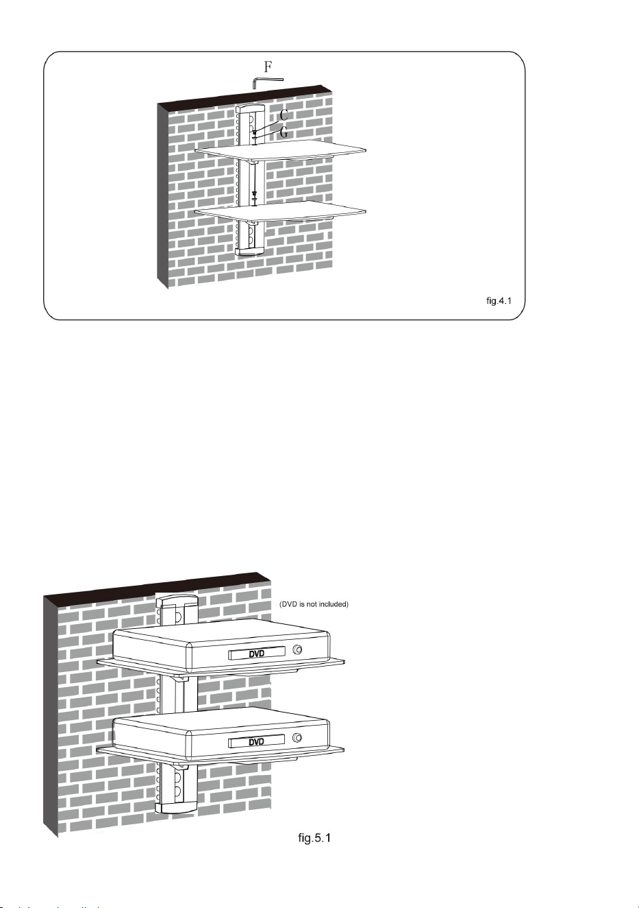
STEP4: INSTALLING THE GLASS SHELF
Place the two glass shelf gently on the two glass holders respectively.
Attach the glass shelves to the glass holders using screws and
plastic bushes, tightening screws with a 3mm Allen key but not
completely at this time. Center the glass shelves over holes,
securely tighten screws with a 3mm Allen key as shown in fig.4.1.

- 9 -
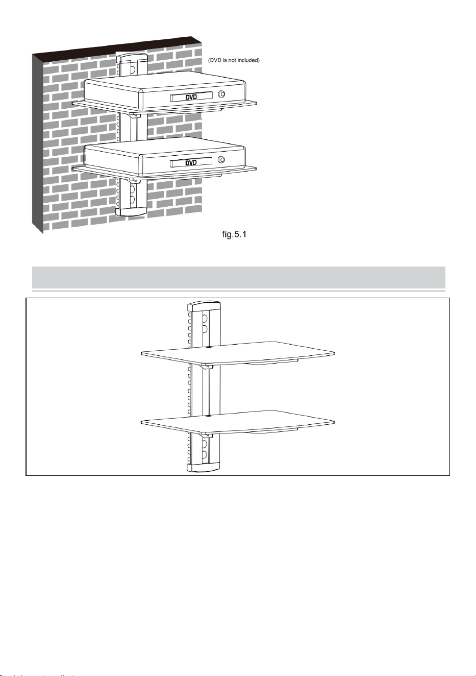
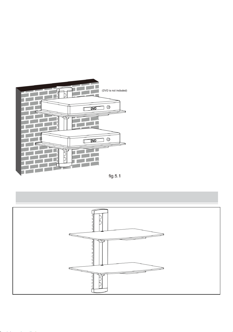
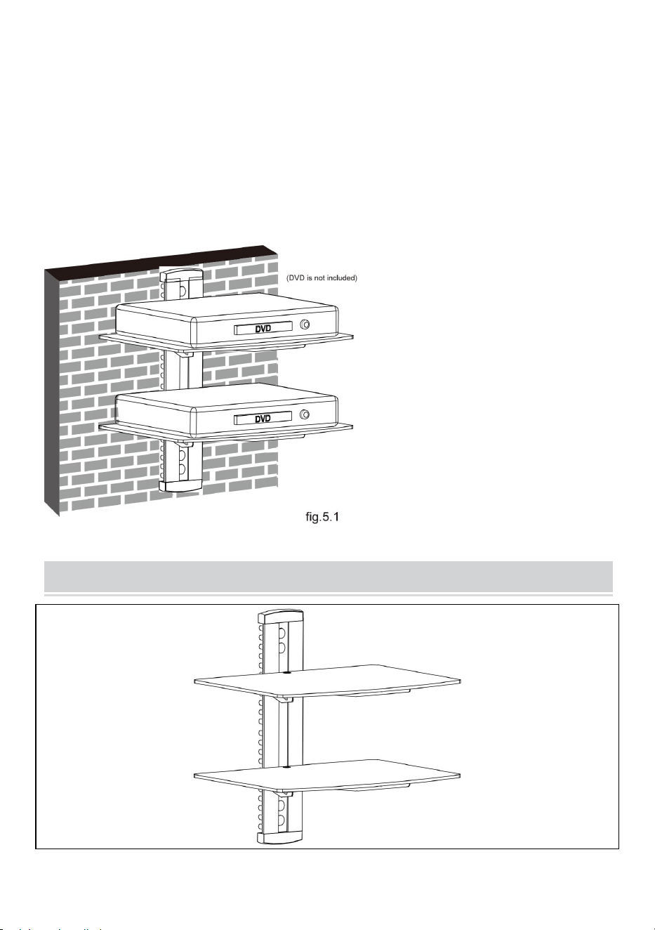
STEP5: CABLE MANAGEMENT
After installing the DVD wall mount, place DVD gently on the
mounted glass shelves. Pull out the cable clip. Insert the cable into
any of the opening of the clip, with one end of the cable inserted in
the clip. Insert the clip into the main pole. Take out the other head of
the cable from another opening of the clip, then push the clip until the
end of the main pole.
COMPLETION
Maintenance
●Once you have mounted the DVD
bracket, ensure that it is securely
fastened and safe to use. Check the
tightness of screws every two months.
●If you have any doubts regarding the
installation, please consult our retailer
or service department for details.

Address: Shuangchenglu 803nong11hao1602A-1609shi, baoshanqu,
shanghai 200000 CN.
Imported to AUS: SIHAO PTY LTD, 1 ROKEVA STREETEASTWOOD
NSW 2122 Australia
Imported to USA: Sanven Technology Ltd., Suite 250, 9166 Anaheim
Place, Rancho Cucamonga, CA 91730
REP
EC
E-CrossStu GmbH
Mainzer Landstr.69, 60329 Frankfurt am Main.
REP
UK
YH CONSULTING LIMITED.
C/O YH Consulting Limited Office 147, Centurion House,
London Road, Staines-upon-Thames, Surrey, TW18 4AX


Technique Assistance et certificat de garantie électronique
www.vevor.com/support
SUPPORT DE COMPOSANT AUDIO
MANUEL DE L' UTILISATEUR
N° DE MODÈLE : CS202
We continue to be committed to provide you tools with competitive price.
"Save Half", "Half Price" or any other similar expressions used by us only represents an
estimate of savings you might benefit from buying certain tools with us compared to the major
top brands and does not necessarily mean to cover all categories of tools offered by us. You
are kindly reminded to verify carefully when you are placing an order with us if you are
actually saving half in comparison with the top major brands.

- 1 -
MODÈLE : CS202
Have product questions? Need technical support? Please feel free to
contact us:
Technical Support and E-Warranty Certificate
www.vevor.com/support
NEED HELP? CONTACT US!
This is the original instruction, please read all manual instructions
carefully before operating. VEVOR reserves a clear interpretation of our
user manual. The appearance of the product shall be subject to the
product you received. Please forgive us that we won't inform you again if
there are any technology or software updates on our product.
Audio Component Stand

- 2 -
AVERTISSEMENT:
Veuillez lire attentivement ce manuel avant d'utiliser le produit. Ne
pas le faire pourrait entraîner des blessures graves.
PRÉCAUTIONS DE MONTAGE
N'installez pas le produit avant d'avoir lu et compris les instructions et
les avertissements fournis dans cette fiche d'installation. Si vous avez
des questions concernant les instructions ou les avertissements,
veuillez contacter votre distributeur local.
Veuillez vous référer au guide d'installation pour connaître les
distances recommandées par rapport au mur afin d'éviter tout risque
de dommages matériels.
Ce produit ne doit être installé que par une personne possédant de
bonnes aptitudes en mécanique, une expérience en construction de
base et une compréhension complète du processus d'installation.
Assurez-vous que la surface d’appui supportera en toute sécurité la
charge combinée de l’équipement et de tout le matériel et
composants attachés.
En cas de montage sur des montants muraux en bois, assurez-vous
que les vis de montage sont ancrées au centre des montants. L’
utilisation d’un détecteur de montants « bord à bord » est fortement
recommandée.
Utilisez toujours un assistant ou un équipement de levage mécanique
pour soulever et positionner l'équipement en toute sécurité.
Serrez fermement les vis, mais sans trop serrer. Un serrage excessif
peut endommager les articles, réduisant considérablement leur
pouvoir de maintien.
Ce produit est destiné à un usage intérieur uniquement. L'utilisation de

- 3 -
ce produit à l'extérieur pourrait entraîner une défaillance du produit et
des blessures.
Ne dépassez jamais la capacité de charge maximale.
CONSERVER LES INSTRUCTIONS
PRÉCAUTIONS D'UTILISATION
POUR ÉVITER DES BLESSURES GRAVES ET LA MORT PAR
BASCULEMENT :
5. Ce produit n'est pas un jouet . Gardez les enfants loin de cet article.
6. Ne dépassez pas les capacités de poids avant de déménager.
7. Utilisez uniquement sur une surface plane, dure et lisse capable de
supporter en toute sécurité un support de composant audio entièrement
chargé.
8. Utiliser uniquement comme prévu. Inspectez avant chaque utilisation et
ne pas utiliser si les pièces sont desserrées ou endommagées.
TECHNICAL SPECIFICATIONS
Modèle
CS202
dimensions du produit
(LxlxH)(mm)
425*240*320
Taille d'emballage
(LxlxH)(mm)
410*298*55
Poids net / kg)
Environ 2,6
Poids brut (kg)
Environ 3
- 4 -
*Les produits tels que les spécifications, l'apparence et la conception
sont sujets à modification sans préavis.
PACKAGE CONTENTS
Outils nécessaires
Vis à tête Phillips D rivière (Longueur : 200 mm ( à l' exclusion
de la poignée ))

- 5 -
Perceuse électrique et mèche à maçonnerie de 8 mm pour l'
installation de murs en béton
Stylo de marquage
Marteau
ASSEMBLY STEPS
ÉTAPE 1-a : MONTAGE MURAL SUR MONTANTS EN
BOIS :
● Utilisez un détecteur de montants pour localiser les bords des
montants. Il est fortement recommandé d’utiliser un détecteur de
montants bord à bord. Tracez une ligne verticale au centre de
chaque montant en fonction de leurs bords.
● Placez la plaque murale sur le mur comme modèle et marquez le
centre.
des quatre trous de montage. Assurez-vous que les trous de
montage sont
sur la ligne médiane du montant.
● Percez quatre trous de 1/8" (3 mm) de diamètre et 1,2" (30 mm) de
profondeur . Sécurisez-le à l'aide quatre vis(A), assurez-vous que le
mur la plaque est de niveau comme indiqué sur la fig.1.1.

- 6 -
ÉTAPE 1-b : BRIQUE SOLIDE ET BLOC DE BÉTON
MONTAGE:
● Utilisez la plaque murale comme modèle pour marquer les
emplacements de quatre trous sur le mur, ainsi que montré sur la
fig.1.2.
● Pré-percez ces trous avec un foret à maçonnerie de 8 mm , en
assurant une profondeur d'au moins 50 mm. Insérez une ancre à
béton (B) dans chacun de ces trous.
● Fixez la plaque murale au mur à l'aide de quatre vis (A),
assurez-vous que la plaque murale est de niveau montré sur la
fig.1.2.
- 7 -
ÉTAPE 2 : ASSEMBLAGE DU PORTE-VERRE
● Fixez la pièce de connexion au support de verre à l'aide de deux
vis , en laissant un espace de 3 mm comme indiqué sur la fig.2.1.
● Répétez la même procédure pour assembler l'autre porte-verre.
ÉTAPE 3 : INSTALLATION DU PORTE-VERRE
- 8 -
● Insérez les deux supports de verre dans la plaque murale le long
du rail de la plaque murale à la hauteur souhaitée respectivement,
puis serrez les quatre vis avec une clé Allen de 3 mm comme
indiqué sur la fig.3.1.
● Insérez deux couvercles décoratifs respectivement en haut et en
bas de la plaque murale et installez quatre couvercles en plastique.
comme le montre la fig.3.2.
● Vous pouvez régler la hauteur des porte-verres selon vos besoins.
Desserrez les vis avec une clé Allen de 3 mm (mais pas retirer) pour
régler les supports de verre à la hauteur souhaitée, puis serrer les
vis avec une clé Allen de 3 mm comme montré sur la fig.3.2.
- 9 -
ÉTAPE 4 : INSTALLATION DE L'ÉTAGÈRE EN VERRE
Placez délicatement les deux étagères en verre sur les deux
supports en verre. Fixez les étagères en verre au verre supports à
l'aide de vis et de douilles en plastique, en serrant les vis avec une
clé Allen de 3 mm, mais pas complètement à ce stade. temps.
Centrez les étagères en verre sur les trous, serrez solidement les vis
avec une clé Allen de 3 mm comme indiqué sur la fig.4.1.
ÉTAPE 5 : GESTION DES CÂBLES
Après avoir installé le support mural pour DVD, placez délicatement
le DVD sur les étagères en verre montées. Retirez le serre-câble .
Insérez le câble dans l'une des ouvertures du clip, avec une
extrémité du câble insérée dans le clip . J'insère le clipsez-le sur le
poteau principal . Sortez l'autre tête du câble d'une autre ouverture
du clip, puis poussez le clip jusqu'à l'extrémité du poteau principal.
- 10 -
COMPLETION
Maintenance
●Once you have mounted the DVD
bracket, ensure that it is securely
fastened and safe to use. Check the
tightness of screws every two months.
●If you have any doubts regarding the
installation, please consult our retailer
or service department for details.

Adresse : Shuangchenglu 803nong11hao1602A-1609shi, baoshanqu,
Shanghai 200000 CN.
Importé en Australie : SIHAO PTY LTD, 1 ROKEVA STREETASTWOOD
NSW 2122 Australie
Importé aux États-Unis : Sanven Technology Ltd., Suite 250, 9166
Anaheim Place, Rancho Cucamonga, CA 91730
REP
EC
E-CrossStu GmbH
Mainzer Landstr.69, 60329 Frankfurt am Main.
REP
UK
YH CONSULTING LIMITED.
C/O YH Consulting Limited Office 147, Centurion House,
London Road, Staines-upon-Thames, Surrey, TW18 4AX


We continue to be committed to provide you tools with competitive price.
"Save Half", "Half Price" or any other similar expressions used by us only represents an
estimate of savings you might benefit from buying certain tools with us compared to the major
top brands and does not necessarily mean to cover all categories of tools offered by us. You
are kindly reminded to verify carefully when you are placing an order with us if you are
actually saving half in comparison with the top major brands.
- 1 -
MODELL: CS202
Have product questions? Need technical support? Please feel free to
contact us:
Technical Support and E-Warranty Certificate
www.vevor.com/support
NEED HELP? CONTACT US!
This is the original instruction, please read all manual instructions
carefully before operating. VEVOR reserves a clear interpretation of our
user manual. The appearance of the product shall be subject to the
product you received. Please forgive us that we won't inform you again if
there are any technology or software updates on our product.
Audio Component Stand

- 2 -
WARNUNG:
Bitte lesen Sie dieses Handbuch vor der Verwendung des Produkts
sorgfältig durch. Andernfalls kann es zu schweren Verletzungen
kommen.
VORSICHTSMASSNAHMEN BEI DER
MONTAGE
Installieren Sie das Produkt erst, wenn Sie die Anweisungen und
Warnungen in diesem Installationsblatt gelesen und verstanden haben.
Wenn Sie Fragen zu den Anweisungen oder Warnungen haben,
wenden Sie sich bitte an Ihren Händler vor Ort.
Um Sachschäden zu vermeiden, beachten Sie die empfohlenen
Abstände zur Wand in der Installationsanleitung.
Dieses Produkt sollte nur von jemandem installiert werden, der über
gute mechanische Fähigkeiten, Erfahrung im Grundbau und ein
umfassendes Verständnis des Installationsvorgangs verfügt.
Stellen Sie sicher, dass die Standfläche die Gesamtlast des Geräts
und aller angeschlossenen Hardware und Komponenten sicher trägt.
Bei der Montage an Holzwandpfosten achten Sie darauf, dass die
Befestigungsschrauben in der Mitte der Pfosten verankert sind. Die
Verwendung eines „ Rand-zu-Rand “ -Pfostensuchers wird dringend
empfohlen.
Verwenden Sie zum sicheren Anheben und Positionieren von Geräten
immer einen Assistenten oder ein mechanisches Hebezeug.
Ziehen Sie die Schrauben fest an, aber nicht zu fest. Zu festes
Anziehen kann die Teile beschädigen und ihre Haltekraft stark
verringern.
Dieses Produkt ist nur für den Gebrauch in Innenräumen vorgesehen.
Bei Verwendung im Freien kann es zu Produktfehlern und
Verletzungen kommen.
Überschreiten Sie niemals die maximale Tragfähigkeit.

- 3 -
SPEICHERN SIE DIE ANLEITUNG
VORSICHTSMASSNAHMEN BEIM
GEBRAUCH
UM SCHWERE VERLETZUNGEN UND TOD DURCH KIPPEN ZU
VERMEIDEN:
9. Dieses Produkt ist kein Spielzeug . Halten Sie Kinder von diesem Artikel
fern.
10. Überschreiten Sie nicht die Gewichtskapazität vor dem Umzug.
11. Nur auf einer flachen, harten und glatten Oberfläche verwenden, die
einen voll beladenen Audiokomponentenständer sicher tragen kann.
12. Nur bestimmungsgemäß verwenden. Vor jedem Gebrauch überprüfen
und nicht verwenden, wenn Teile lose oder beschädigt sind.
TECHNICAL SPECIFICATIONS
Modell
CS202
Technische Daten
(L x B x H) (mm)
425*240*320
Verpackungsgröße (L x
B x H) (mm)
410*298*55
Nettogewicht / kg)
Etwa 2,6
Bruttogewicht (kg)
Ungefähr 3
- 4 -
*Produkte wie Spezifikationen, Aussehen und Design können ohne
vorherige Ankündigung geändert werden.
PACKAGE CONTENTS
Werkzeuge benötigt
Kreuzschlitzschraube D river (Länge: 200 mm ( ohne Griff ) )
Elektrische Bohrmaschine und 8 - mm - Steinbohrer für die
Installation von Betonwänden

- 5 -
Markierstift
Hammer
ASSEMBLY STEPS
SCHRITT 1-a: HOLZSTÄNDER-WANDMONTAGE:
● Verwenden Sie einen Balkenfinder, um die Kanten der Balken zu
lokalisieren. Es wird dringend empfohlen, einen Balkenfinder zu
verwenden, der von Kante zu Kante reicht. Zeichnen Sie eine
vertikale Linie in der Mitte jedes Balkens, basierend auf seinen
Kanten.
● Legen Sie die Wandplatte als Schablone an die Wand und
markieren Sie die Mitte
der vier Befestigungslöcher. Stellen Sie sicher, dass die
Befestigungslöcher
auf der Mittellinie des Bolzens.
● Bohren Sie vier Löcher mit einem Durchmesser von 3 mm und
einer Tiefe von 30 mm . Befestigen Sie sie mit vier Schrauben (A),
stellen Sie sicher, dass die Wand Die Platte ist waagerecht , wie in
Abb. 1.1 dargestellt.

- 6 -
SCHRITT 1-b: MASSIVE ZIEGEL UND BETONBLOCK
MONTAGE:
● Verwenden Sie die Wandplatte als Vorlage, um die Positionen der
vier Löcher an der Wand zu markieren. dargestellt in Abb. 1.2.
● Bohren Sie diese Löcher mit einem 8-mm-Steinbohrer vor und
achten Sie auf eine Tiefe von mindestens 50 mm. Setzen Sie in
jedes dieser Löcher einen Betonanker (B) ein.
● Befestigen Sie die Wandplatte Befestigen Sie die Wandplatte mit
vier Schrauben (A) an der Wand. Stellen Sie sicher, dass die
Wandplatte dargestellt in Abb. 1.2.
- 7 -
SCHRITT 2: MONTAGE DES GLASHALTERS
● Befestigen Sie das Verbindungsstück mit zwei Schrauben am
Glashalter und lassen Sie dabei einen Abstand von 3 mm, wie in Abb.
2.1 gezeigt.
● Wiederholen Sie die gleiche Methode, um den anderen Glashalter
zusammenzubauen.
- 8 -
SCHRITT 3: INSTALLATION DES GLASHALTERS
● Setzen Sie die beiden Glashalter entlang der Wandplattenschiene
jeweils in der gewünschten Höhe in die Wandplatte ein und ziehen
Sie dann die vier Schrauben mit einem 3-mm-Inbusschlüssel fest,
wie in Abb. 3.1 gezeigt.
● Setzen Sie jeweils zwei dekorative Abdeckungen an der Ober- und
Unterseite der Wandplatte ein und montieren Sie vier
Kunststoffabdeckungen wie in Abb. 3.2 gezeigt.
● Sie können die Höhe der Glashalter nach Bedarf anpassen. Lösen
Sie die Schrauben mit einem 3mm Inbusschlüssel (aber nicht
entfernen), um die Glashalter auf die gewünschte Höhe einzustellen
und dann die Schrauben mit einem 3mm Inbusschlüssel
festzuziehen, wie wie in Abb. 3.2 dargestellt.

- 9 -
SCHRITT 4: INSTALLATION DES GLASREGAL
Legen Sie die beiden Glasregale vorsichtig auf die beiden Glashalter.
Befestigen Sie die Glasregale an den Glas Halter mit Schrauben und
Kunststoffbuchsen, die Schrauben mit einem 3mm Inbusschlüssel
festziehen , jedoch nicht vollständig an diesem Zeit. Zentrieren Sie
die Glasböden über den Löchern und ziehen Sie die Schrauben mit
einem 3-mm-Inbusschlüssel fest an, wie in Abb. 4.1 gezeigt.
SCHRITT 5: KABELMANAGEMENT

- 10 -
Nachdem Sie die DVD-Wandhalterung installiert haben, legen Sie
die DVD vorsichtig auf die montierten Glasregale. Ziehen Sie den
Kabelclip heraus . Stecken Sie das Kabel in eine der Öffnungen des
Clips, wobei ein Ende des Kabels im Clip steckt . Stecken Sie das
Zum Einklipsen in die Hauptstange . Nehmen Sie den anderen
Kabelkopf aus einer anderen Öffnung des Clips heraus und drücken
Sie dann den Clip bis zum Ende der Hauptstange.
COMPLETION
Maintenance
●Once you have mounted the DVD
bracket, ensure that it is securely
fastened and safe to use. Check the
tightness of screws every two months.
●If you have any doubts regarding the
installation, please consult our retailer
or service department for details.
Adresse : Shuangchenglu 803nong11hao1602A-1609shi, Baoshanqu,
Shanghai 200000 CN.
Nach AUS importiert: SIHAO PTY LTD, 1 ROKEVA
STREETEASTWOOD NSW 2122 Australien
Importiert in die USA: Sanven Technology Ltd., Suite 250, 9166 Anaheim
Place, Rancho Cucamonga, CA 91730
REP
EC
E-CrossStu GmbH
Mainzer Landstr.69, 60329 Frankfurt am Main.
REP
UK
YH CONSULTING LIMITED.
C/O YH Consulting Limited Office 147, Centurion House,
London Road, Staines-upon-Thames, Surrey, TW18 4AX


Tecnico Supporto e certificato di garanzia elettronica
www.vevor.com/support
SUPPORTO PER COMPONENTI AUDIO
MANUALE D' USO
MODELLO N.: CS202
We continue to be committed to provide you tools with competitive price.
"Save Half", "Half Price" or any other similar expressions used by us only represents an
estimate of savings you might benefit from buying certain tools with us compared to the major
top brands and does not necessarily mean to cover all categories of tools offered by us. You
are kindly reminded to verify carefully when you are placing an order with us if you are
actually saving half in comparison with the top major brands.

- 1 -
MODELLO: CS202
Have product questions? Need technical support? Please feel free to
contact us:
Technical Support and E-Warranty Certificate
www.vevor.com/support
NEED HELP? CONTACT US!
This is the original instruction, please read all manual instructions
carefully before operating. VEVOR reserves a clear interpretation of our
user manual. The appearance of the product shall be subject to the
product you received. Please forgive us that we won't inform you again if
there are any technology or software updates on our product.
Audio Component Stand

- 2 -
AVVERTIMENTO:
Si prega di leggere attentamente questo manuale prima di utilizzare il
prodotto. In caso contrario, si potrebbero causare lesioni gravi.
PRECAUZIONI DI MONTAGGIO
Non installare il prodotto prima di aver letto e compreso le istruzioni e
le avvertenze fornite in questa scheda di installazione. In caso di
domande riguardanti istruzioni o avvertenze, contattare il distributore
locale.
Fare riferimento alla guida di installazione per le distanze consigliate
dalla parete per evitare il rischio di danni materiali.
Questo prodotto deve essere installato solo da qualcuno con buone
attitudini meccaniche, esperienza nella costruzione di base e una
piena comprensione del processo di installazione.
Assicurarsi che la superficie di supporto supporti in modo sicuro il
carico combinato dell'apparecchiatura e di tutto l'hardware e i
componenti collegati.
Se si effettua il montaggio su montanti a parete in legno, assicurarsi
che le viti di montaggio siano ancorate al centro dei montanti. Si
consiglia vivamente l'uso di un rilevatore di perni “ da bordo a bordo ” .
Utilizzare sempre un assistente o un'attrezzatura di sollevamento
meccanica per sollevare e posizionare l'attrezzatura in sicurezza.
Stringere saldamente le viti, ma non stringerle eccessivamente. Un
serraggio eccessivo può danneggiare gli articoli, riducendo
notevolmente la loro capacità di tenuta.
Questo prodotto è destinato esclusivamente all'uso interno. L'utilizzo
di questo prodotto all'aperto potrebbe causare guasti al prodotto e
lesioni personali.
Non superare mai la capacità di carico massima.
SALVA LE ISTRUZIONI

- 3 -
USARE LE PRECAUZIONI
PER PREVENIRE LESIONI GRAVI E MORTE DOVUTE AL
RIBALTAMENTO:
13. Questo prodotto non è un giocattolo . Tenere i bambini lontani da
questo oggetto.
14. Non superare le capacità di peso prima di spostarsi.
15. Utilizzare solo su una superficie piana, dura e liscia in grado di
supportare in modo sicuro un supporto per componenti audio
completamente carico.
16. Utilizzare solo come previsto. Ispezionare prima di ogni utilizzo e non
utilizzare se le parti sono allentate o danneggiate.
TECHNICAL SPECIFICATIONS
Modello
CS202
Dimensioni del prodotto
(LxLxA)(mm)
425*240*320
Dimensioni imballo
(LxLxA) (mm)
410*298*55
Peso netto
(chilogrammo)
Circa 2 .6
Peso lordo
(chilogrammo)
Circa 3
*Prodotti quali specifiche, aspetto e design sono soggetti a modifiche
senza preavviso.
- 4 -
PACKAGE CONTENTS
Strumenti richiesti
Vite con testa a croce D fiume (Lunghezza: 200 mm ( esclusa la
maniglia ))
Trapano elettrico e B it per muratura da 8 mm per l' installazione
di pareti in cemento
Pennarello

- 5 -
Martello
ASSEMBLY STEPS
FASE1-a: MONTAGGIO A PARETE CON BORDI IN
LEGNO:
● Utilizzare un cercatore di perni per individuare i bordi dei perni. Si
consiglia vivamente di utilizzare un rilevatore di perni da bordo a
bordo. Disegna una linea verticale al centro di ciascun perno in base
ai bordi.
● Posiziona la piastra sul muro come modello e segna il centro
dei quattro fori di montaggio. Assicurarsi che i fori di montaggio siano
sulla linea centrale del perno.
● Praticare quattro fori da 1/8" (3 mm) di diametro e 1,2" (30 mm) di
profondità . Proteggilo utilizzando quattro viti(A), assicurarsi che il
muro la piastra sia a livello come mostrato in fig.1.1.

- 6 -
FASE1-b: MATTONI PIENI E BLOCCHI DI CEMENTO
MONTAGGIO:
● Utilizzare la piastra a muro come modello per contrassegnare le
posizioni dei quattro fori sulla parete mostrato in fig.1.2.
● Preforare questi fori con una punta da muratura da 8 mm ,
assicurando una profondità di almeno 50 mm. Inserisci un'ancora di
cemento (B) in ciascuno di questi fori.
● Attaccare la piastra a muro al muro utilizzando quattro viti(A),
assicurarsi che la piastra a muro sia a livello mostrato in fig.1.2.

- 7 -
STEP2: MONTAGGIO DEL SUPPORTO IN VETRO
● Fissare il pezzo di connessione al supporto del vetro utilizzando
due viti , lasciando uno spazio di 3 mm come mostrato in fig.2.1.
● Ripetere lo stesso procedimento per assemblare l'altro
portabicchiere.
STEP3: INSTALLAZIONE DEL SUPPORTO IN VETRO

- 8 -
● Inserire i due portabicchieri nella piastra da muro lungo la guida
della piastra da muro rispettivamente all'altezza desiderata, quindi
serrare le quattro viti con una chiave a brugola da 3 mm come
mostrato in fig.3.1.
● Inserire due coperture decorative rispettivamente nella parte
superiore e inferiore della piastra a muro e installare quattro
coperture in plastica come mostrato in fig.3.2.
● È possibile regolare l'altezza dei portabicchieri secondo necessità.
Allentare le viti con una chiave a brugola da 3 mm (ma non
rimuovere) per regolare i supporti del vetro all'altezza desiderata e
quindi serrare le viti con una chiave a brugola da 3 mm come
mostrato in fig.3.2.
- 9 -
PASSO 4: INSTALLAZIONE DEL RIPIANO IN VETRO
Posizionare delicatamente i due ripiani in vetro rispettivamente sui
due portabicchieri. Attaccare i ripiani in vetro al vetro supporti
utilizzando viti e boccole in plastica, serrando le viti con una chiave a
brugola da 3 mm ma non completamente tempo. Centrare i ripiani in
vetro sui fori, serrare saldamente le viti con una chiave a brugola da
3 mm come mostrato in fig.4.1.
PASSO 5: GESTIONE DEI CAVI
- 10 -
Dopo aver installato il supporto a parete per DVD, posizionare
delicatamente il DVD sui ripiani in vetro montati. Estrarre il
fermacavo . Inserire il cavo in una qualsiasi delle aperture della clip,
con un'estremità del cavo inserita nella clip . inserisco il agganciarlo
al palo principale . Estrarre l'altra estremità del cavo da un'altra
apertura della clip, quindi spingere clip fino alla fine del palo
principale.
COMPLETION
Maintenance
●Once you have mounted the DVD
bracket, ensure that it is securely
fastened and safe to use. Check the
tightness of screws every two months.
●If you have any doubts regarding the
installation, please consult our retailer
or service department for details.

Indirizzo : Shuangchenglu 803nong11hao1602A-1609shi, baoshanqu,
shanghai 200000 CN.
Importato in AUS: SIHAO PTY LTD, 1 ROKEVA STREETEASTWOOD
NSW 2122 Australia
Importato negli Stati Uniti: Sanven Technology Ltd., Suite 250, 9166
Anaheim Place, Rancho Cucamonga, CA 91730
REP
EC
E-CrossStu GmbH
Mainzer Landstr.69, 60329 Frankfurt am Main.
REP
UK
YH CONSULTING LIMITED.
C/O YH Consulting Limited Office 147, Centurion House,
London Road, Staines-upon-Thames, Surrey, TW18 4AX


We continue to be committed to provide you tools with competitive price.
"Save Half", "Half Price" or any other similar expressions used by us only represents an
estimate of savings you might benefit from buying certain tools with us compared to the major
top brands and does not necessarily mean to cover all categories of tools offered by us. You
are kindly reminded to verify carefully when you are placing an order with us if you are
actually saving half in comparison with the top major brands.

- 1 -
MODELO: CS202
Have product questions? Need technical support? Please feel free to
contact us:
Technical Support and E-Warranty Certificate
www.vevor.com/support
NEED HELP? CONTACT US!
This is the original instruction, please read all manual instructions
carefully before operating. VEVOR reserves a clear interpretation of our
user manual. The appearance of the product shall be subject to the
product you received. Please forgive us that we won't inform you again if
there are any technology or software updates on our product.
Audio Component Stand

- 2 -
ADVERTENCIA:
Lea atentamente este manual antes de utilizar el producto. De lo
contrario, podrían producirse lesiones graves.
PRECAUCIONES DE MONTAJE
No instale el producto hasta que haya leído y comprendido las
instrucciones y advertencias proporcionadas en esta hoja de
instalación. Si tiene alguna pregunta sobre cualquiera de las
instrucciones o advertencias, comuníquese con su distribuidor local.
Consulte la guía de instalación para conocer las distancias
recomendadas desde la pared para evitar el riesgo de daños a la
propiedad.
Este producto sólo debe ser instalado por alguien con buenas
aptitudes mecánicas, experiencia en construcción básica y un
conocimiento completo del proceso de instalación.
Asegúrese de que la superficie de soporte soporte de manera segura
la carga combinada del equipo y todos los herrajes y componentes
adjuntos.
Si lo monta en montantes de pared de madera, asegúrese de que los
tornillos de montaje estén anclados en el centro de los montantes. Se
recomienda encarecidamente el uso de un detector de vigas de
“ borde a borde ” .
Utilice siempre un asistente o un equipo de elevación mecánico para
levantar y colocar el equipo de forma segura.
Apriete los tornillos firmemente, pero no los apriete demasiado.
Apretar demasiado puede dañar los artículos, reduciendo en gran
medida su poder de sujeción.
Este producto está destinado únicamente para uso en interiores. El
uso de este producto al aire libre podría provocar fallas en el producto
y lesiones personales.
Nunca exceda la capacidad de carga máxima.

- 3 -
GUARDE LAS INSTRUCCIONES
PRECAUCIONES DE USO
PARA EVITAR LESIONES GRAVES Y LA MUERTE POR VUELCO:
17. Este producto no es un juguete . Mantenga a los niños alejados de
este artículo.
18. No exceda las capacidades de peso antes de moverse.
19. Úselo únicamente sobre una superficie plana, dura y lisa capaz de
soportar de manera segura un soporte para componentes de audio
completamente cargado.
20. Úselo únicamente según lo previsto. Inspeccione antes de cada uso y
no lo utilice si las piezas están sueltas o dañadas.
TECHNICAL SPECIFICATIONS
Modelo
CS202
Dimensiones del
producto
(LxAnxAl)(mm)
425*240*320
Tamaño del embalaje
(largo x ancho x alto)
(mm)
410*298*55
Peso neto / kg)
Alrededor de 2,6
Peso bruto (kg)
Alrededor de 3
*Productos como especificaciones, apariencia y diseño están
sujetos a modificaciones sin previo aviso.

- 4 -
PACKAGE CONTENTS
Herramientas necesarias
Tornillo cabeza Phillips D río (Longitud: 200 mm ( excluyendo el
mango H ))
Taladro eléctrico y broca de mampostería de 8 mm para
instalación de paredes de hormigón
Rotulador

- 5 -
Martillo
ASSEMBLY STEPS
PASO 1-a: MONTAJE EN LA PARED DE MONTANTES
DE MADERA:
● Utilice un buscador de vigas para localizar los bordes de las vigas.
Se recomienda encarecidamente utilizar un detector de vigas de
borde a borde. Dibuja una línea vertical en el centro de cada
montante según sus bordes.
● Coloque la placa de pared en la pared como plantilla y marque el
centro.
de los cuatro orificios de montaje. Asegúrese de que los orificios de
montaje estén
en la línea central del montante.
● Taladre cuatro orificios de 1/8” (3 mm) de diámetro y 1,2” (30 mm)
de profundidad . Asegúrelo usando cuatro tornillos (A), asegúrese
de que la pared la placa esté nivelada como se muestra en la fig.1.1.
- 6 -
PASO 1-b: LADRILLO SÓLIDO Y BLOQUE DE
HORMIGÓN
MONTAJE:
● Utilice la placa de pared como plantilla para marcar las
ubicaciones de los cuatro orificios en la pared como se muestra en
la figura 1.2.
● Pretaladre estos agujeros con una broca para mampostería de 8
mm , asegurando una profundidad de al menos 50 mm. Inserte un
anclaje para concreto (B) en cada uno de estos orificios.
● Coloque la placa de pared a la pared usando cuatro tornillos (A),
asegúrese de que la placa de pared esté lo más nivelada posible. se
muestra en la figura 1.2.

- 7 -
PASO 2: MONTAJE DEL SOPORTE DE VIDRIO
● Fije la pieza de conexión al soporte de vidrio usando dos tornillos ,
dejando un espacio de 3 mm como se muestra en la figura 2.1.
● Repita el mismo procedimiento para montar el otro soporte para
vasos.
PASO 3: INSTALACIÓN DEL SOPORTE DE VIDRIO
- 8 -
● Inserte los dos soportes de vidrio en la placa de pared a lo largo
del riel de la placa de pared a la altura deseada respectivamente y
luego apriete los cuatro tornillos con una llave Allen de 3 mm como
se muestra en la figura 3.1.
● Inserte dos cubiertas decorativas en la parte superior e inferior de
la placa de pared respectivamente e instale cuatro cubiertas de
plástico. como se muestra en la figura 3.2.
● Puedes ajustar la altura de los soportes de cristal según sea
necesario. Afloje los tornillos con una llave Allen de 3 mm (pero no
quitar) para ajustar los soportes de vidrio a la altura deseada y luego
apriete los tornillos con una llave Allen de 3 mm como se muestra en
la figura 3.2.
- 9 -
PASO 4: INSTALACIÓN DEL ESTANTE DE VIDRIO
Coloque los dos estantes de vidrio con cuidado sobre los dos
soportes de vidrio respectivamente. Fije los estantes de vidrio al
vidrio. soportes usando tornillos y casquillos de plástico, apretando
los tornillos con una llave Allen de 3 mm, pero no completamente en
este momento. tiempo. Centre los estantes de vidrio sobre los
orificios y apriete firmemente los tornillos con una llave Allen de 3
mm como se muestra en la figura 4.1.
- 10 -
PASO 5: GESTIÓN DE CABLES
Después de instalar el soporte de pared para DVD, coloque el DVD
con cuidado sobre los estantes de vidrio montados. Saque el clip del
cable . Inserte el cable en cualquiera de las aberturas del clip, con
un extremo del cable insertado en el clip . Insertar el clip en el poste
principal . Saque la otra cabeza del cable de otra abertura del clip,
luego empuje el clip hasta el final del poste principal.
COMPLETION
Maintenance
●Once you have mounted the DVD
bracket, ensure that it is securely
fastened and safe to use. Check the
tightness of screws every two months.
●If you have any doubts regarding the
installation, please consult our retailer
or service department for details.

Dirección : Shuangchenglu 803nong11hao1602A-1609shi, baoshanqu,
shanghai 200000 CN.
Importado a AUS: SIHAO PTY LTD, 1 ROKEVA STREETEASTWOOD
NSW 2122 Australia
Importado a EE. UU.: Sanven Technology Ltd., Suite 250, 9166 Anaheim
Place, Rancho Cucamonga, CA 91730
REP
EC
E-CrossStu GmbH
Mainzer Landstr.69, 60329 Frankfurt am Main.
REP
UK
YH CONSULTING LIMITED.
C/O YH Consulting Limited Office 147, Centurion House,
London Road, Staines-upon-Thames, Surrey, TW18 4AX


Techniczny Certyfikat wsparcia i e-gwarancji
www.vevor.com/support
STOJAK NA KOMPONENTY AUDIO
INSTRUKCJA OBSŁUGI
NR MODELU: CS202
We continue to be committed to provide you tools with competitive price.
"Save Half", "Half Price" or any other similar expressions used by us only represents an
estimate of savings you might benefit from buying certain tools with us compared to the major
top brands and does not necessarily mean to cover all categories of tools offered by us. You
are kindly reminded to verify carefully when you are placing an order with us if you are
actually saving half in comparison with the top major brands.

- 1 -
MODEL: CS202
Have product questions? Need technical support? Please feel free to
contact us:
Technical Support and E-Warranty Certificate
www.vevor.com/support
NEED HELP? CONTACT US!
This is the original instruction, please read all manual instructions
carefully before operating. VEVOR reserves a clear interpretation of our
user manual. The appearance of the product shall be subject to the
product you received. Please forgive us that we won't inform you again if
there are any technology or software updates on our product.
Audio Component Stand

- 2 -
OSTRZEŻENIE:
Przed użyciem produktu prosimy o dokładne zapoznanie się z
niniejszą instrukcją. Niezastosowanie się do tego może spowodować
poważne obrażenia.
ŚRODKI OSTROŻNOŚCI PRZY MONTAŻU
Nie instaluj produktu, dopóki nie przeczytasz i nie zrozumiesz
instrukcji i ostrzeżeń zawartych w tym arkuszu instalacyjnym. Jeśli
masz jakiekolwiek pytania dotyczące jakichkolwiek instrukcji lub
ostrzeżeń, skontaktuj się z lokalnym dystrybutorem.
Aby uniknąć ryzyka uszkodzenia mienia, zapoznaj się z instrukcją
montażu, aby zapoznać się z zalecanymi odległościami od ściany.
Ten produkt powinien być instalowany wyłącznie przez osobę
posiadającą dobre zdolności mechaniczne, doświadczenie w
podstawowej konstrukcji i pełne zrozumienie procesu instalacji.
Upewnij się, że powierzchnia nośna bezpiecznie utrzyma łączne
obciążenie sprzętu oraz całego podłączonego sprzętu i komponentów.
W przypadku montażu na drewnianych kołkach ściennych należy
upewnić się, że śruby montażowe są zakotwiczone w środku kołków.
Zdecydowanie zaleca się użycie wykrywacza kołków „ od krawędzi do
krawędzi ” .
Aby bezpiecznie podnosić i ustawiać sprzęt, zawsze używaj asystenta
lub mechanicznego sprzętu do podnoszenia.
Dokręć mocno śruby, ale nie przekręcaj. Nadmierne dokręcenie może
uszkodzić elementy, znacznie zmniejszając ich siłę trzymania.
Ten produkt jest przeznaczony wyłącznie do użytku w
pomieszczeniach zamkniętych. Używanie tego produktu na zewnątrz
może prowadzić do awarii produktu i obrażeń ciała.
Nigdy nie przekraczaj maksymalnego udźwigu.
ZACHOWAJ INSTRUKCJĘ

- 3 -
STOSOWAĆ ŚRODKI OSTROŻNOŚCI
ABY ZAPOBIEC POWAŻNYM OBRAŻeniom LUB ŚMIERCI W
PRZYPADKU WYWROTU:
21. Ten produkt nie jest zabawką . Trzymaj dzieci z daleka od tego
przedmiotu.
22. Nie przekraczaj udźwigu przed przeprowadzką.
23. Używaj wyłącznie na płaskiej, twardej i gładkiej powierzchni, która
może bezpiecznie utrzymać w pełni obciążony stojak na komponenty
audio.
24. Używaj wyłącznie zgodnie z przeznaczeniem. Sprawdź przed każdym
użyciem i nie używaj, jeśli części są luźne lub uszkodzone.
TECHNICAL SPECIFICATIONS
Model
CS202
wymiary produktu
(DxSxW) (mm)
425*240*320
Rozmiar opakowania (dł.
x szer. x wys.) (mm)
410*298*55
Masa netto (kg)
Około 2,6
Waga brutto (kg)
Około 3
*Produkty takie jak dane techniczne, wygląd i konstrukcja mogą
podlegać modyfikacjom bez wcześniejszego powiadomienia.

- 4 -
PACKAGE CONTENTS
Wymagane narzędzia
Śruba z łbem krzyżowym D rzeka (Długość: 200 mm ( bez
rączki ) )
Wiertarka elektryczna i mur o grubości 8 mm B do montażu
ścian betonowych
Znakowanie piórem

- 5 -
Młotek
ASSEMBLY STEPS
KROK 1-a: MONTAŻ NA ŚCIANIE NA KOSTKACH
DREWNIANYCH:
● Użyj wykrywacza kołków, aby zlokalizować krawędzie kołków.
Zdecydowanie zaleca się użycie wykrywacza kołków od krawędzi do
krawędzi. Narysuj pionową linię wzdłuż środka każdego słupka w
oparciu o ich krawędzie.
● Umieść płytkę ścienną na ścianie jako szablon i zaznacz środek
z czterech otworów montażowych. Upewnij się, że otwory
montażowe są
na linii środkowej słupka.
● Wywierć cztery otwory o średnicy 1/8” (3 mm) i głębokości 1,2” (30
mm) . Zabezpiecz go za pomocą cztery śruby (A), upewnij się, że
ściana płyta jest wypoziomowana , jak pokazano na rys. 1.1.

- 6 -
KROK 1-b: CEGŁA LITA I BLOK BETONOWY
MONTOWANIE:
● Użyj płytki ściennej jako szablonu do zaznaczenia lokalizacji
czterech otworów na ścianie pokazano na rys.1.2.
● Wywierć wstępnie te otwory wiertłem do muru o średnicy 8 mm ,
zapewniając głębokość co najmniej 50 mm. Włóż kotwę do betonu
(B) w każdy z tych otworów.
● Przymocuj płytę ścienną do ściany za pomocą czterech śrub (A),
upewnij się, że płyta ścienna jest wypoziomowana pokazano na
rys.1.2.
- 7 -
KROK 2: MONTAŻ UCHWYTU NA SZKŁO
● Przymocuj element łączący do szklanego uchwytu za pomocą
dwóch śrub , pozostawiając 3 mm odstęp, jak pokazano na rys. 2.1.
● Powtórz tę samą procedurę, aby zamontować drugi uchwyt na
szklankę.
KROK 3: MONTAŻ UCHWYTU NA SZKŁO
- 8 -
● Włóż dwa szklane uchwyty do płyty ściennej wzdłuż szyny płyty
ściennej odpowiednio na żądaną wysokość, a następnie dokręć
cztery śruby kluczem imbusowym 3 mm, jak pokazano na rys.3.1.
● Włóż dwie dekoracyjne osłony odpowiednio na górę i dół płyty
ściennej i zamontuj cztery plastikowe osłony jak pokazano na
rys.3.2.
● Wysokość uchwytów na szklanki można regulować według
potrzeb. Poluzuj śruby za pomocą klucza imbusowego 3 mm (ale nie
wyjąć), aby wyregulować uchwyty szklane na żądaną wysokość, a
następnie dokręcić śruby kluczem imbusowym 3 mm pokazano na
rys.3.2.

- 9 -
KROK 4: MONTAŻ SZKLANEJ PÓŁKI
Delikatnie umieść obie szklane półki na dwóch szklanych uchwytach.
Przymocuj szklane półki do szyby uchwyty za pomocą śrub i tulejek
z tworzywa sztucznego, śruby dokręcające kluczem imbusowym 3
mm, ale nie do końca czas. Wyśrodkuj szklane półki nad otworami,
mocno dokręć śruby kluczem imbusowym 3 mm, jak pokazano na
rys. 4.1.
KROK 5: ZARZĄDZANIE KABLAMI
Po zainstalowaniu uchwytu ściennego DVD, delikatnie umieść DVD
na zamontowanych szklanych półkach. Wyciągnij zacisk kabla .
Włóż kabel do dowolnego otworu zacisku, tak aby jeden koniec
kabla był włożony do zacisku . Wstawiam przypiąć do głównego
słupa . Wyjmij drugą główkę kabla z innego otworu zacisku, a
następnie wciśnij ją zaczep do końca głównego słupa.

- 10 -
COMPLETION
Maintenance
●Once you have mounted the DVD
bracket, ensure that it is securely
fastened and safe to use. Check the
tightness of screws every two months.
●If you have any doubts regarding the
installation, please consult our retailer
or service department for details.

Adres : Shuangchenglu 803nong11hao1602A-1609shi, baoshanqu,
szanghaj 200000 CN.
Import do AUS: SIHAO PTY LTD, 1 ROKEVA STREETEASTWOOD NSW
2122 Australia
Import do USA: Sanven Technology Ltd., Suite 250, 9166 Anaheim Place,
Rancho Cucamonga, CA 91730
REP
EC
E-CrossStu GmbH
Mainzer Landstr.69, 60329 Frankfurt am Main.
REP
UK
YH CONSULTING LIMITED.
C/O YH Consulting Limited Office 147, Centurion House,
London Road, Staines-upon-Thames, Surrey, TW18 4AX


We continue to be committed to provide you tools with competitive price.
"Save Half", "Half Price" or any other similar expressions used by us only represents an
estimate of savings you might benefit from buying certain tools with us compared to the major
top brands and does not necessarily mean to cover all categories of tools offered by us. You
are kindly reminded to verify carefully when you are placing an order with us if you are
actually saving half in comparison with the top major brands.

- 1 -
MODEL: CS202
Have product questions? Need technical support? Please feel free to
contact us:
Technical Support and E-Warranty Certificate
www.vevor.com/support
NEED HELP? CONTACT US!
This is the original instruction, please read all manual instructions
carefully before operating. VEVOR reserves a clear interpretation of our
user manual. The appearance of the product shall be subject to the
product you received. Please forgive us that we won't inform you again if
there are any technology or software updates on our product.
Audio Component Stand

- 2 -
WAARSCHUWING:
Lees deze handleiding zorgvuldig door voordat u het product
gebruikt. Als u dit niet doet, kan dit leiden tot ernstig letsel.
MONTAGEVOORZORGSMAATREGELEN
Installeer het product pas nadat u de instructies en waarschuwingen in
dit installatieblad hebt gelezen en begrepen. Als u vragen heeft over
een van de instructies of waarschuwingen, neem dan contact op met
uw plaatselijke distributeur.
Raadpleeg de installatiehandleiding voor de aanbevolen afstanden tot
de muur om het risico op materiële schade te voorkomen.
Dit product mag alleen worden geïnstalleerd door iemand met goede
mechanische vaardigheden, ervaring in de basisconstructie en een
volledig begrip van het installatieproces.
Zorg ervoor dat het ondersteunende oppervlak de gecombineerde
belasting van de apparatuur en alle aangesloten hardware en
componenten veilig kan dragen.
Zorg er bij montage op houten muurstijlen voor dat de
montageschroeven in het midden van de stijlen zijn verankerd. Het
gebruik van een “ rand tot rand ” stud finder wordt ten zeerste
aanbevolen.
Gebruik altijd een assistent of mechanische hefapparatuur om
apparatuur veilig op te tillen en te positioneren.
Draai de schroeven stevig vast, maar niet te vast. Te vast aandraaien
kan de voorwerpen beschadigen, waardoor hun houdkracht
aanzienlijk wordt verminderd.
Dit product is uitsluitend bedoeld voor gebruik binnenshuis. Als u dit
product buitenshuis gebruikt, kan dit leiden tot productstoringen en
persoonlijk letsel.
Overschrijd nooit het maximale draagvermogen.
BEWAAR DE INSTRUCTIE

- 3 -
GEBRUIK VOORZORGSMAATREGELEN
OM ERNSTIG LETSEL EN DE DOOD DOOR KANTELEN TE
VOORKOMEN:
25. Dit product is geen speelgoed . Houd kinderen uit de buurt van dit
artikel.
26. Overschrijd de gewichtscapaciteiten niet voordat u gaat verhuizen.
27. Alleen gebruiken op een vlak, hard en glad oppervlak dat een volledig
geladen audiocomponentstandaard veilig kan ondersteunen.
28. Alleen gebruiken zoals bedoeld. Inspecteer het apparaat vóór elk
gebruik en gebruik het niet als er onderdelen loszitten of beschadigd zijn.
TECHNICAL SPECIFICATIONS
Model
CS202
Productafmetingen
(LxBxH)(mm)
425*240*320
Verpakkingsgrootte
(LxBxH) (mm)
410*298*55
Netto gewicht / kg)
Ongeveer 2,6
Bruto gewicht (kg)
Ongeveer 3
*Producten zoals specificaties, uiterlijk en ontwerp kunnen zonder
voorafgaande kennisgeving worden gewijzigd.
- 4 -
PACKAGE CONTENTS
Benodigde gereedschappen
Kruiskopschroef D- rivier (Lengte: 200 mm ( exclusief de
handgreep ))
Elektrische boor en 8 mm metselwerk B it voor installatie van
betonnen muren
Markeerpen
Hamer
- 5 -
ASSEMBLY STEPS
STAP1-a: WOOD STUD MUURBEVESTIGING:
● Gebruik een stud finder om de randen van de noppen te
lokaliseren. Het wordt sterk aanbevolen om een edge-to-edge stud
finder te gebruiken. Teken een verticale lijn door het midden van elke
stijl op basis van hun randen.
● Plaats de muurplaat als sjabloon op de muur en markeer het
midden
van de vier montagegaten. Zorg ervoor dat de montagegaten
aanwezig zijn
op de middellijn van de nop.
● Boor vier gaten met een diameter van 3 mm en een diepte van 30
mm . Beveilig het met behulp van vier schroeven (A), zorg ervoor dat
de muur vastzit plaat waterpas is , zoals getoond in fig.1.1.
- 6 -
STAP1-b: MASSIEF BAKSTENEN EN BETONBLOK
MONTAGE:
● Gebruik de muurplaat als sjabloon om de locaties van vier gaten
op de muur te markeren getoond in figuur 1.2.
● Boor deze gaten voor met een steenboor van 8 mm en zorg voor
een diepte van minimaal 50 mm. Steek een betonanker (B) in elk
van deze gaten.
● Bevestig de muurplaat aan de muur met behulp van vier
schroeven (A), zorg ervoor dat de muurplaat waterpas staat getoond
in figuur 1.2.
STAP2: MONTEREN VAN DE GLAZENHOUDER
- 7 -
● Bevestig het verbindingsstuk aan de glashouder met behulp van
twee schroeven en laat een ruimte van 3 mm vrij, zoals
weergegeven in fig.2.1.
● Herhaal dezelfde methode om de andere glashouder te monteren.
STAP3: DE GLAZENHOUDER INSTALLEREN
● Steek de twee glashouders respectievelijk op de gewenste hoogte
in de muurplaat langs de muurplaatrail en draai vervolgens de vier
schroeven vast met een 3 mm inbussleutel, zoals weergegeven in
fig.3.1.
- 8 -
● Plaats twee decoratieve afdekkingen respectievelijk op de boven-
en onderkant van de muurplaat en installeer vier plastic afdekkingen
zoals getoond in figuur 3.2.
● Je kunt de hoogte van de glashouders naar wens aanpassen.
Draai de schroeven los met een inbussleutel van 3 mm (maar niet
verwijderen) om de glashouders op de gewenste hoogte af te stellen
en draai vervolgens de schroeven vast met een inbussleutel van 3
mm getoond in figuur 3.2.
STAP4: HET INSTALLEREN VAN DE GLAZEN PLANK
Plaats de twee glasplaten voorzichtig op respectievelijk de twee
glashouders. Bevestig de glazen planken aan het glas houders met
behulp van schroeven en plastic bussen, schroeven aandraaien met
een inbussleutel van 3 mm, maar niet helemaal op dit punt tijd.
Centreer de glazen planken over de gaten en draai de schroeven
stevig vast met een 3 mm inbussleutel, zoals weergegeven in afb.
4.1.
- 9 -
STAP5: KABELBEHEER
Nadat u de dvd-wandhouder hebt geïnstalleerd, plaatst u de dvd
voorzichtig op de gemonteerde glazen planken. Trek de kabelclip
eruit . Steek de kabel in een van de openingen van de clip, waarbij
het ene uiteinde van de kabel in de clip wordt gestoken . Steek de
clip in de hoofdpaal . Haal de andere kop van de kabel uit een
andere opening van de clip en druk vervolgens op de knop clip tot
het einde van de hoofdpaal.
Maintenance
●Once you have mounted the DVD
bracket, ensure that it is securely
fastened and safe to use. Check the
tightness of screws every two months.
●If you have any doubts regarding the
installation, please consult our retailer
or service department for details.
- 10 -
COMPLETION

Adres : Shuangchenglu 803nong11hao1602A-1609shi, baoshanqu,
shanghai 200000 CN.
Geïmporteerd naar AUS: SIHAO PTY LTD, 1 ROKEVA
STREETEASTWOOD NSW 2122 Australië
Geïmporteerd naar de VS: Sanven Technology Ltd., Suite 250, 9166
Anaheim Place, Rancho Cucamonga, CA 91730
REP
EC
E-CrossStu GmbH
Mainzer Landstr.69, 60329 Frankfurt am Main.
REP
UK
YH CONSULTING LIMITED.
C/O YH Consulting Limited Office 147, Centurion House,
London Road, Staines-upon-Thames, Surrey, TW18 4AX


We continue to be committed to provide you tools with competitive price.
"Save Half", "Half Price" or any other similar expressions used by us only represents an
estimate of savings you might benefit from buying certain tools with us compared to the major
top brands and does not necessarily mean to cover all categories of tools offered by us. You
are kindly reminded to verify carefully when you are placing an order with us if you are
actually saving half in comparison with the top major brands.

- 1 -
MODELL: CS202
Have product questions? Need technical support? Please feel free to
contact us:
Technical Support and E-Warranty Certificate
www.vevor.com/support
NEED HELP? CONTACT US!
This is the original instruction, please read all manual instructions
carefully before operating. VEVOR reserves a clear interpretation of our
user manual. The appearance of the product shall be subject to the
product you received. Please forgive us that we won't inform you again if
there are any technology or software updates on our product.
Audio Component Stand

- 2 -
VARNING:
Läs denna bruksanvisning noggrant innan du använder produkten.
Underlåtenhet att göra det kan leda till allvarliga skador.
FÖRSIKTIGHETSÅTGÄRDER FÖR
MONTERING
Installera inte produkten förrän du har läst och förstått instruktionerna
och varningarna i detta installationsblad. Om du har några frågor
angående någon av instruktionerna eller varningarna, kontakta din
lokala distributör.
Se installationsguiden för rekommenderade avstånd från väggen för
att undvika risken för egendomsskador.
Denna produkt bör endast installeras av någon med god mekanisk
förmåga, erfarenhet av grundläggande konstruktion och full förståelse
för installationsprocessen.
Se till att den stödjande ytan säkert kan bära den kombinerade
belastningen av utrustningen och all ansluten hårdvara och
komponenter.
Om du monterar på väggreglar i trä, se till att monteringsskruvarna är
förankrade i mitten av reglarna. Användning av en " kant till kant "
dubbsökare rekommenderas starkt.
Använd alltid en assistent eller mekanisk lyftutrustning för att säkert
lyfta och positionera utrustning.
Dra åt skruvarna ordentligt, men dra inte åt för hårt. För hårt
åtdragning kan skada föremålen, vilket avsevärt minskar deras
hållkraft.
Denna produkt är endast avsedd för inomhusbruk. Användning av
denna produkt utomhus kan leda till produktfel och personskada.
Överskrid aldrig den maximala lastkapaciteten.
SPARA INSTRUKTIONEN

- 3 -
ANVÄND FÖRSIKTIGHETSÅTGÄRDER
FÖR ATT FÖRHINDRA ALLVARLIGA SKADA OCH DÖDSFALL VID
VÄLLNING:
29. Denna produkt är inte en leksak . Håll barn borta från detta föremål.
30. Överskrid inte viktkapaciteten innan du flyttar.
31. Använd endast på en plan, hård och slät yta som säkert kan stödja ett
fullt laddat ljudkomponentstativ.
32. Använd endast som avsett. Inspektera före varje användning och
använd inte om delar är lösa eller skadade.
TECHNICAL SPECIFICATIONS
Modell
CS202
Produktens mått
(LxBxH)(mm)
425*240*320
Förpackningsstorlek(LxB
xH)(mm)
410*298*55
Nettovikt (kg)
Cirka 2,6
Bruttovikt (kg)
Cirka 3
*Produkter som specifikationer, utseende och design kan ändras
utan föregående meddelande.

- 4 -
PACKAGE CONTENTS
Verktyg krävs
Phillips Head Screw D river (Längd: 200 mm ( exklusive H
andle ))
Elektrisk borr och 8 mm M asonry B it för installation av
betongvägg
Markeringspenna
Hammare
- 5 -
ASSEMBLY STEPS
STEG1-a: VÄGGMONTERING Trärebb:
● Använd en dubbsökare för att lokalisera dubbarnas kanter. Det
rekommenderas starkt att använda en kant-till-kant dubbsökare. Rita
en vertikal linje ner i mitten av varje stift baserat på deras kanter.
● Placera väggplattan på väggen som mall och markera mitten
av de fyra monteringshålen. Se till att monteringshålen är
på dubbens mittlinje.
● Borra fyra hål med diametern 3 mm (1,2 tum) 30 mm djupa . Säkra
den med hjälp av fyra skruvar(A), se till att väggen plattan är jämn
som visas i fig.1.1.
STEG1-b: SOLID TEGE OCH BETONGBLOCK
- 6 -
MONTERING:
● Använd väggplattan som mall för att markera placeringen av fyra
hål på väggen visas i fig.1.2.
● Förborra dessa hål med en 8 mm murkrona , se till att djupet är
minst 50 mm. Sätt in ett betongankare (B) i vart och ett av dessa hål.
● Fäst väggplattan till väggen med hjälp av fyra skruvar(A), se till att
väggplattan är jämn som visas i fig.1.2.
STEG 2: MONTERING AV GLASHÅLLARE
● Fäst anslutningsstycket till glashållaren med två skruvar , lämna ett
3 mm utrymme som visas i fig.2.1.
● Upprepa samma metod för att montera den andra glashållaren.
- 7 -
STEG 3: INSTALLERA GLASHÅLLARE
● Sätt in de två glashållarna i väggplattan längs väggplattans skena
på önskad höjd respektive, och dra sedan åt fyra skruvar med en 3
mm insexnyckel som visas i fig.3.1.
● Sätt i två dekorativa kåpor på toppen och botten av väggplattan
respektive och installera fyra plastkåpor som visas i fig.3.2.
● Du kan justera höjden på glashållarna efter behov. Lossa
skruvarna med en 3 mm insexnyckel (men inte ta bort) för att justera

- 8 -
glashållarna till önskad höjd och dra sedan åt skruvarna med en 3
mm insexnyckel som visas i fig.3.2.
STEG 4: INSTALLERA GLASHYLLAN
Placera de två glashyllorna försiktigt på de två glashållarna. Fäst
glashyllorna på glaset hållare med skruvar och plastbussningar, dra
åt skruvarna med en 3 mm insexnyckel men inte helt vid denna tid.
Centrera glashyllorna över hålen, dra åt skruvarna ordentligt med en
3 mm insexnyckel som visas i fig.4.1.

- 9 -
STEG 5: KABELHANTERING
När du har installerat DVD-väggfästet, placera DVD-skivan försiktigt
på de monterade glashyllorna. Dra ut kabelklämman . Sätt in kabeln
i någon av öppningarna på klämman, med ena änden av kabeln
insatt i klämman . Jag sätter in klämma fast i huvudstolpen . Ta ut det
andra huvudet på kabeln från en annan öppning i klämman och tryck
sedan på klämma till slutet av huvudstolpen.
COMPLETION
Maintenance
●Once you have mounted the DVD
bracket, ensure that it is securely
fastened and safe to use. Check the
tightness of screws every two months.
●If you have any doubts regarding the
installation, please consult our retailer
or service department for details.

Adress : Shuangchenglu 803nong11hao1602A-1609shi, baoshanqu,
shanghai 200000 CN.
Importerad till AUS: SIHAO PTY LTD, 1 ROKEVA STREETEASTWOOD
NSW 2122 Australien
Importerad till USA: Sanven Technology Ltd., Suite 250, 9166 Anaheim
Place, Rancho Cucamonga, CA 91730
REP
EC
E-CrossStu GmbH
Mainzer Landstr.69, 60329 Frankfurt am Main.
REP
UK
YH CONSULTING LIMITED.
C/O YH Consulting Limited Office 147, Centurion House,
London Road, Staines-upon-Thames, Surrey, TW18 4AX