
Ci series
Installation Manual
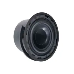
Ci5 & Ci5-V
Loudspeaker
Ci5 BLK/Ci5-V BLK/Ci5 WHT/Ci5-V WHT

Congratulations on your new Ci loudspeaker system from Blaze Audio.
The Ci series is a feature packed range of loudspeakers designed for use in a large variety of
applications. Emphasis is placed on discreet modern design, ease of installation, wide and uniform
coverage and excellent sound quality without the use of electronic signal processing.
Included in the box:
Two speakers
Two Sliders
Mounting screws
Mounting template
Safety letter
The series provides 100 degree vertical x 100 degree horizontal dispersion and comprises 2”, 4”, and 5”
models, with an optional high-impedance mode. The patented 90° triangular ABS cabinet with built-in
sliders (available on the 4” and 5” models only) not only ts perfectly into vertical and horizontal corners
without showing visible brackets, but also offers a variety of unique placement options. These include
coupling 2-3 speakers together to increase coverage to 180 or 270 degrees when mounted on walls,
ceilings, or free-standing corners (the Ci2 allows a maximum of 2 coupled cabinets for 180-degree
coverage).
For enhanced bass performance, the Ci series can be teamed indoors with our C8S and C12S
subwoofers.
Introduction
Connections.
The Ci models are tted with a screw terminal on the front bafe. he Ci5 and Ci5-V features an oval
cable port (9 mm x 20 mm), with contacts supporting wire sizes up to 4 sq. mm.
Important: Always connect the red amplier output (+) to the red speaker terminal input and the black
amplier output (-) to the black speaker input. If reversed, the stereo imaging will be blurred and the
bass output will be dramatically reduced.
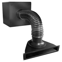
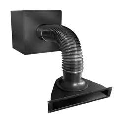
How to connect the cables.
It is important that you run the speaker cables through the port BEFORE mounting your new Blaze
Audio speakers! The speakers are equipped with discreet cable terminals placed on the front bafe
behind the front cover – and it is not possible to run the cables to the terminals once the speakers have
been installed.
Getting started
1
2
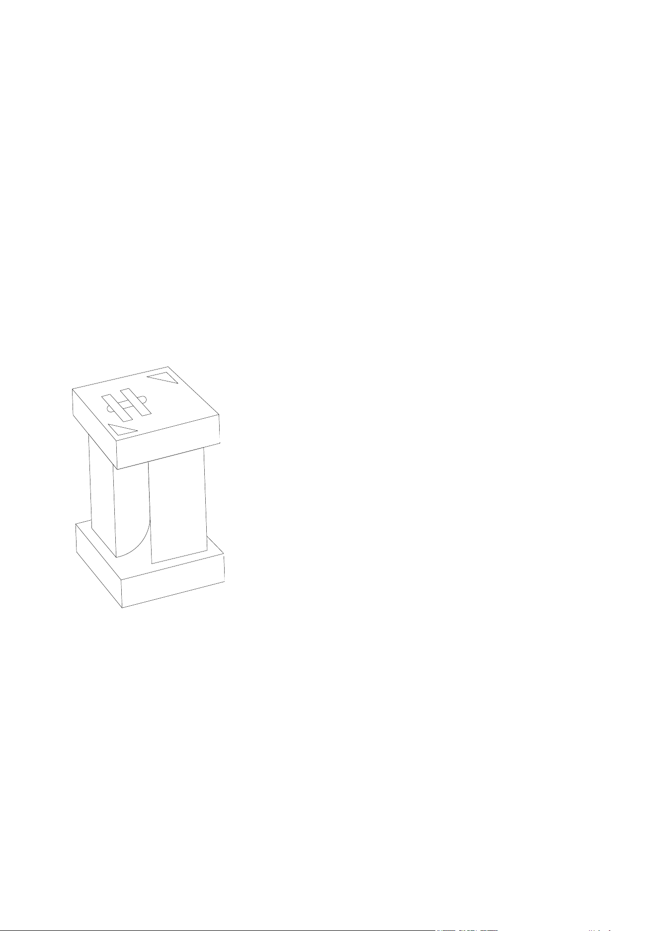
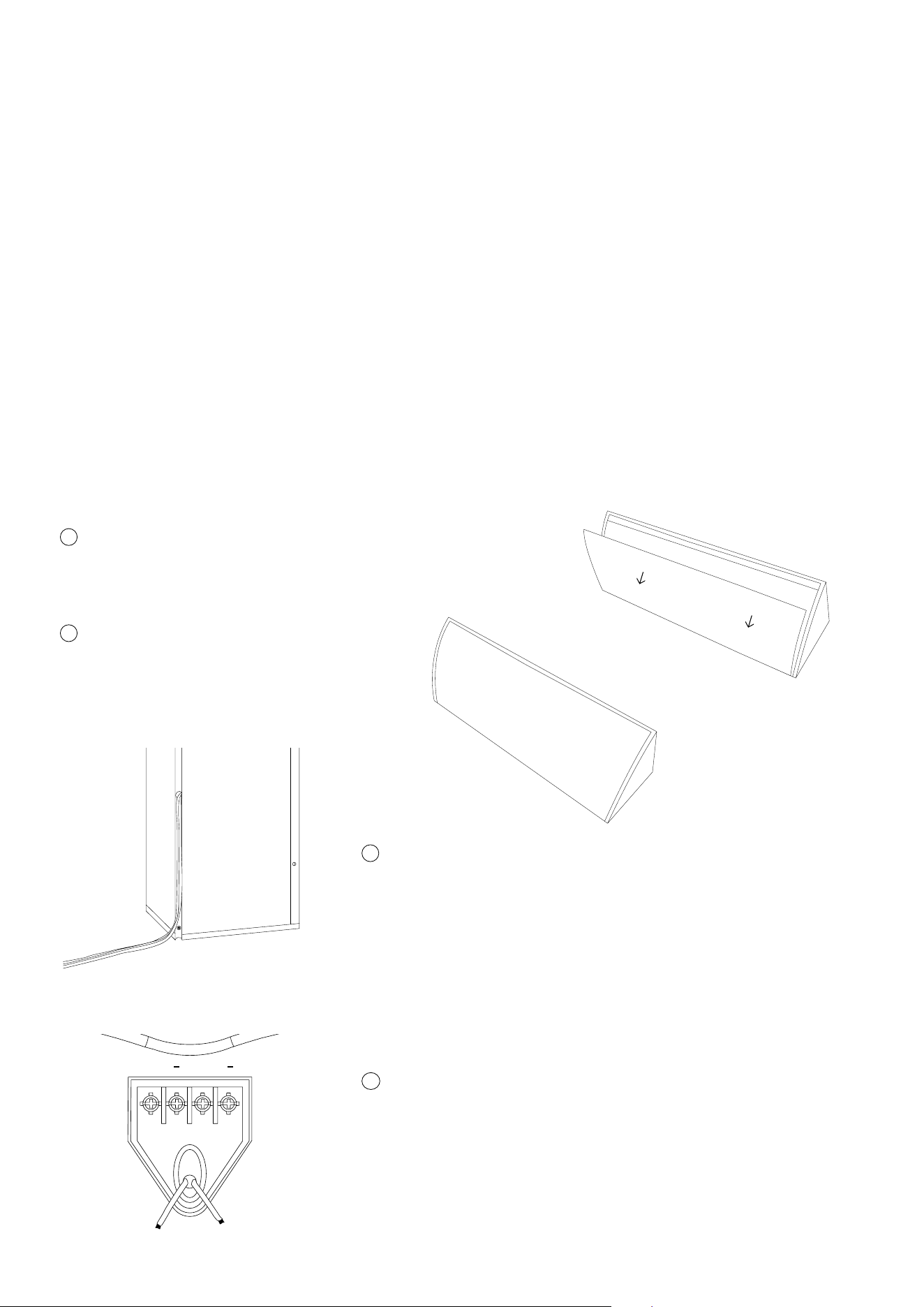
Remove the front cover to access the cable terminal:
Push the cover from the side of the cabinet to
squeeze it out of the grove.
Make sure the amplier is turned off.
3
Run the speaker cable through the tube positioned at the
rear of the cabinet to the terminal at the front bafe.
* Note that it is easier to install the speaker rst and
mount the cable to the terminal after the speaker is
mounted to the wall.
If you use the sliders, you can mount the speaker cables
to the terminal at this point. If you use the mounting
points, it is easier to install the speaker rst and mount
the cable to the terminal after the speaker is mounted to
the wall.
4
+ +
The Ci series can be mounted either in corners, on wall and ceilings with the integrated mounting points
or the slider bars. They can also be coupled together to extend coverage.
The Ci5 and Ci5-V are light, but please make sure that the wall or ceiling is solid and can support the
weight of the speaker before installing. Also, make sure that you comply with all local health and safety
regulations. (See the Safety Letter included in the packaging.) The low weight and the sliders allow the
products to be installed easily by one person.
Vertical or horizontal installation in corners.
If you prefer to mount the speaker in a corner, you should:
Installation
1
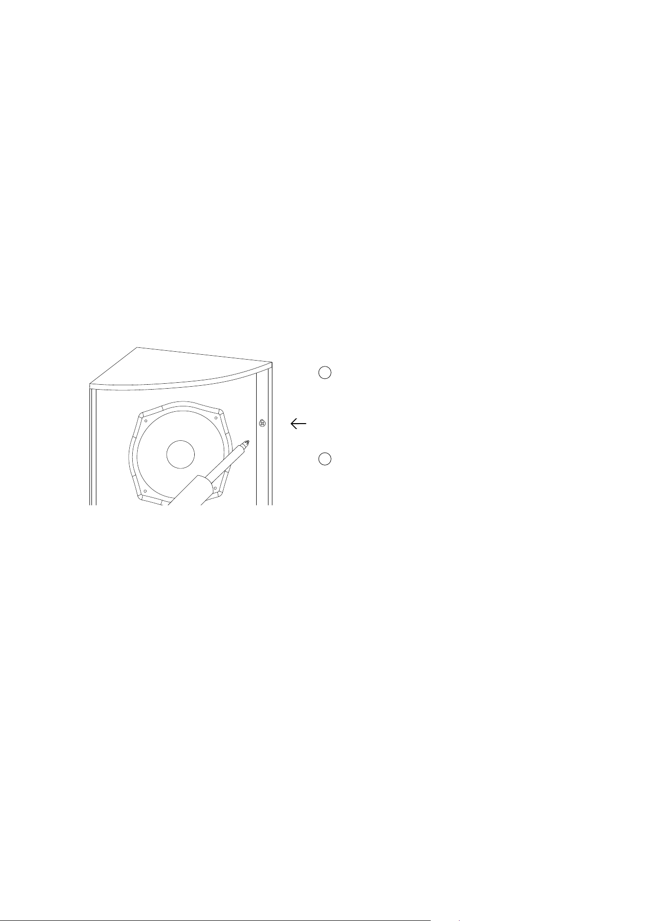
Remove the front cover and you’ll see the
mounting holes in the left and right hand side of
the cabinet.
• Drill holes in the wall using 4 mm rawl plugs and the enclosed 3,5 mm at head screws.
• Reposition the speakers in desired position and mount the screws.
Mounting in corners that are not exactly 90 degrees:
• If the corner is less than 90 degrees, simply place the speaker cabinet as deep in the corner
as possible and use all mounting points. This will leave a little space behind the cabinet and
the walls, but the speakers will still appear with a nice nish in the corner.
• If the corner is more than 90 degrees, we recommend mounting only one of the sides of the
speaker cabinet onto the wall – and leave some air behind the other side of the cabinet.
This will not be visible from the front, and the speakers will still present themselves with a
nice nish.
2
Place the mounting template in desired position
and mark drilling positions by shading through
the six mounting holes
If the wall or ceiling is soft, or if you want to mount the speakers on the wall
or ceiling away from the corner.
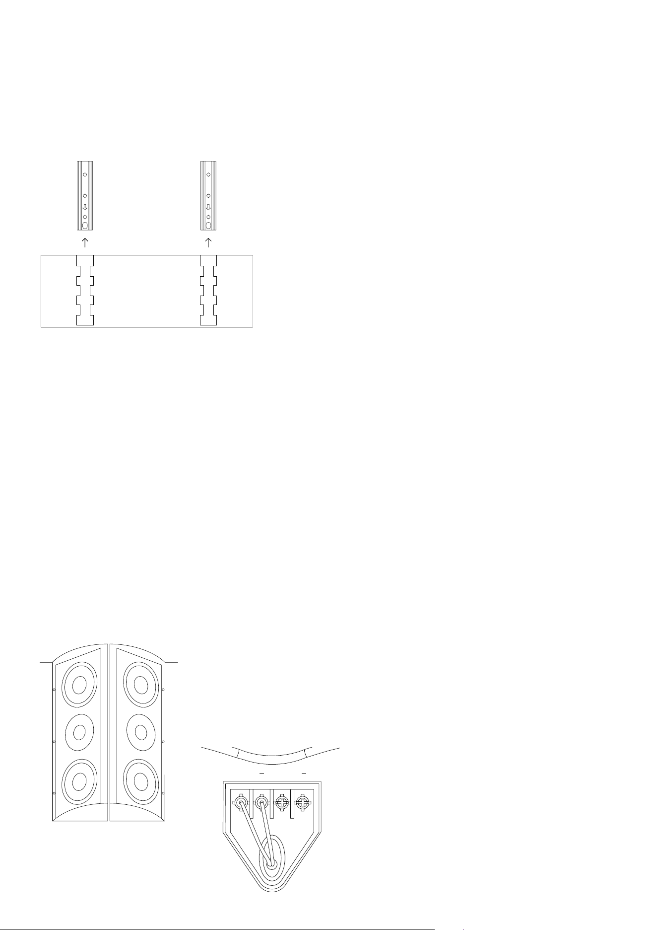
• Mount the sliders to the wall or ceiling using the
provided template. Ensure the arrow on the slider
points towards the front of the speaker.
• If the wall is solid, one slider is sufcient to hold the
speaker.
• Slide the speaker onto the sliders
• Finally x the speaker to the wall or ceiling by
screwing through the cabinet and slider into the wall or
ceiling, using the upper and lower mounting points.
Slide the speaker onto the sliders.
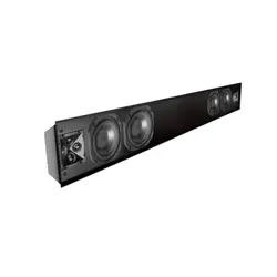
Our Ci series speakers are designed with an emphasis on uniform and wide controlled dispersion.
The acoustic design allows the speakers to be coupled together to expand coverage:
• One Ci cabinet offers 100x100 degree dispersion.
• Two Ci cabinets can be coupled together back to back and then mounted ush onto walls and ceilings
while offering 200 degrees of coverage with minimum phase cancellation.
• Mount the speakers back to back on wall or ceiling using either the sliders or integrated mounting
points. Use 4 mm blots between 38 and 42 mm long to screw the cabinets together.
Likewise, three cabinets can be mounted together to cover
270 degrees around a free-standing corner. Simply couple
three cabinets together using 9x3 mm bolts and mount the
speakers to the corner with the integrated mounting points.
Connect the red (+) and black (-) speaker
cable to the left + and right - screw terminals.
Use the right + - terminals to link to another
speaker.
+ +
Mounting the cabinets together

Cables
Operation
Speaker cables present the amplier with different loads. Cables with high capacitance, high inductance
and high impedance have a strong negative inuence on sound quality as well as amplier reliability. In
order to get the most out of the speaker system, avoid using thin speaker cables.
As a rule of thumb, 2 mm
2
(14 AWG) cable can be used for lengths up to 20 meters. 4 mm
2
(11 AWG)
cable should be used for lengths over 20 meters. For lengths over 50 meters, most ampliers will
become unstable and sound quality is reduced signicantly.
To minimize power loss and response variations, please refer to the following table for guidance,
showing the maximum recommended cable length relative to impedance and cable thickness:
Cable size/load
2 sq mm.
2,5 sq mm.
4 sq mm.
8 Ω
20 m / 65 ft.
30 m / 100 ft.
60 m /200 ft.
4 Ω
10 m /32 ft.
15 m /50 ft.
30 m /100 ft.
2 Ω
5 m / 16 ft.
7,5 m / 25ft.
15 m / 50 ft.
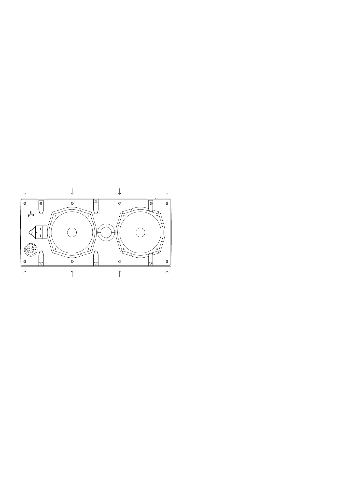
Tweeter protection.
Ci4 and Ci5 feature a tweeter protection circuit. If a microphone is used, or if the speaker is used in
environments with very high level of background sound, we recommend turning on the protection
circuit. For home installations, we recommend turning off the protection.
To enable, move the PTC switch to ON.
To disengage, move the switch to OFF.
Tweeter
Protection

Outdoor mounting.
The Ci4 and Ci5 are is IP65 rated, so they can be placed outside. (See the Safety Letter included in the
packaging.) If installed outdoors, the insulation of the cabling should be resistant to water as well as the
effects of temperature and ultraviolet radiation from the sun. Recommended insulations are:
UV stabilized polyethylene, neoprene, Teon™, Silicon™, and Hypalon™.
The following materials are not recommended, because of potentially shorter life expectancy in outdoor
environments: rubber, PVC (polyvinylchloride), polypropylene, polyurethane, and nylon. UV-stabilized
polypropylene may be acceptable.
Safety wire.
In installation terms, the top-boxes are as much brackets as they are speakers, because they mount ush
to the walls and ceilings, so no safety wire is needed (just like on traditional speaker installations, you
don’t use a safety wire from a bracket to the wall).
70V
100V
Mode selection.
Ci4-V & Ci5-V can be driven in 8 ohm or 70 V or
100 V mode. The input tap selection switch is placed
behind the grille. On Ci4-V the taps are 3,75, 7,5,
and 15 watt output in 70 V mode and 7,5 and 15 W
output in 100 V mode. On Ci5-V the taps are 3,75,
7,5, 15 and 30 W output in 70 V mode and 7,5, 15
and 30 W output in 100 V mode. The rotary switch is
operated with a at-head #7 screw driver.
Speaker presets.
Recommended loudspeaker presets are available at blaze-audio.com/support and are designed for use
with Blaze Audio’s PowerZone™ Connect DSP-enabled amplier series.
Recommended amplier.
The Ci speaker series has a high minimum impedance, making them an easy load for ampliers. We
recommend using Blaze Audio’s PowerZone™ Connect DSP-enabled ampliers with power ratings that
exceed the loudspeakers’ power handling capacity (see specications). As with all loudspeaker systems,
power handling depends on the quality and size of the amplier. If the amplier is overdriven and runs
into clipping, the drivers can be damaged, even if the amplier’s output is lower than the speaker’s
power handling capacity. When selecting an amplier, keep in mind that a higher power amplier
operating without distortion will typically sound better and cause less damage to the loudspeaker than a
lower power amplier that is constantly clipping.
Warranty.
For warranty information, please refer to your local Blaze Audio distributor or dealer, or contact us
directly.
Service.
Woofers can be easily replaced by unscrewing them from the bafe using a Hexagon H3 bit. The
tweeter is clicked into the horn section of the bafe from the rear of the bafe. To access the tweeter,
remove the bafe by unscrewing the four Philips screws.
Spare parts for your Blaze Audio speakers are available through your local Blaze Audio distributor or
dealer. Please contact us directly, in case you are not able to source spare parts locally.
Turn the tweeter counter-clockwise to remove
it from the bafe. Reinstall the new tweeter
by pressing it towards the horn section of the
bafe and turn it clock wise until you hear a
“click”.
The crossover is removed by unscrewing the
Philips head screws and removing the cables
from the drivers.
©2025 Sonance. All rights reserved. Sonance is a registered trademarks of Dana Innovations.
Due to continuous product improvement, all features and specifications are subject to change without notice.
For the latest Sonance product specification information visit our website at www.sonance.com.
SONANCE • 991 Calle Amanecer • San Clemente, CA 92673 USA • Phone: (949) 492-7777 • Technical Support: (949) 492-7777 • www.sonance.com • 07.01.25
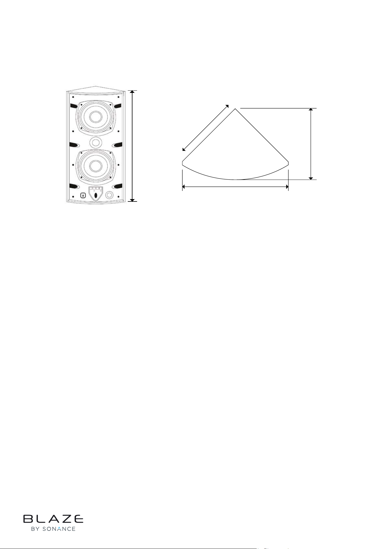
Specications
Rev H 23/06/2025
150 mm
210 mm
139 mm
450 mm
Sensitivity SPL / 1W @ 1m: 88 dB
Maximum SPL, Long Term: 107 dB
Maximum SPL, Peak: 113 dB
Frequency response: 55-20.000 Hz
Nominal impedance: 8 Ω
Dispersion: 100° vertical / 100° horizontal
Ingress Protection: IP65
Recommended amplifier, Ci5: 50-100 W
Recommended amplifier, Ci5-V: 45-90 W
Ci5-V transformer taps: 70 V: 3,75, 7,5, 15, 30 W
100 V: 7,5, 15, 30 W
Measurements: 450 x 210 x 139 mm
(17.72 x 8.27 x 5.47 in)
Weight: Ci5: 2,85 kg (6.28 lb)
Ci5-V: 3,45 kg (7.61 lb)
Colour: White (RAL9010)
Black (RAL9005)