MAKE THE MOST OF YOUR
CARE & USE/INSTALLATION
SIDE BURNER / POWER BURNER
ACCESSORY

2
WARNINGS
• Never use dented, rusty or damaged propane cylinders. Never store additional or empty propane cylinders in
the cabinet or in the vicinity of this or any other appliance. Do not store propane cylinders indoors or on their
sides.
• Children should never be left alone or unattended in an area where an accessory is located. Place your
accessory well away from areas where children play. Do not store items that may interest children in or around
the area of your accessory, in your accessory cart, or in the masonry enclosure.
• Never move the accessory when hot. When in use, portions of the accessory are hot enough to cause severe
burns.
• Always maintain the required clearances from combustibles as detailed. Accessories are designed for out door
use only. Never use in a garage, building, shed, breezeway, or other enclosed area. Do not use this equipment
under any unprotected overhead combustible construction.
• Grill accessories are not designed or certifi ed for and are not to be installed in or on recreational vehicles,
portable trailers, boats or any other moving installation.
• Always have an ABC Fire Extinguisher accessible - never attempt to extinguish a grease fi re with water or
other liquids.
• Storing your accessory: Store your accessory in a well-ventilated area. If stored indoors, detach and leave LP
cylinder outdoors in a well-ventilated area away from heat and away from where children may tamper with it.
• Keep any electrical supply cord and the fuel supply hose away from any heated surfaces. Electrical cords
should be placed away from walkways to avoid tripping hazard.
• Do not repair or replace any part of the accessory unless specifi cally recommended in this manual. Other
service should be performed by a qualifi ed technician.
• If the accessory is installed by a professional installer or technician, be sure that he/she shows you where
your gas supply shut-o is located. All gas lines must have a shut-o that is readily and easily accessible. If
you smell gas, check for gas leaks immediately. Check only with a soap and water solution. (See INDEX: “Leak
Testing” for further details.) Never check for gas leaks with an open fl ame.
• Inspect the LP gas supply hose prior to each use of the accessory. If there is evidence of excessive abrasion or
wear, or the hose is cut, it must be replaced before using the accessory.
THIS MANUAL MUST REMAIN WITH THE PRODUCT OWNER FOR FUTURE REFERENCE
This product complies with ANSI standard Z21.58 /
CSA 1.6 and has been tested and approved by Intertek.
To obtain replacement parts or service contact:
Lynx Grills, Inc.
62201 Hwy 82 West
Greenwood, MS 38930
888-289-5969
3
WARNINGS
READ THIS MANUAL CAREFULLY and completely before using your grill to reduce the risk of:
Fire
Burn hazard, personal injury or property damage
Ruined steaks or other unpleasant cooking experiences
Unapproved installation or servicing.
THIS PRODUCT IS DESIGNED FOR OUTDOOR USE ONLY. Improper installation, adjustment, alteration,
service or maintenance can cause property damage, injury or death.
Read this manual thoroughly before installation, use, or servicing of this product.
IF YOU SMELL GAS:
Shut o all gas supply lines to the grill accessory
Extinguish any open fl ames.
If odor continues, keep everyone away from the
unit and immediately call your gas supplier or
your fi re department.
1. DO NOT store or use gasoline or other
fl ammable vapors and liquids in the vicinity of
this or any other appliance.
2. An LP cylinder not connected for use shall not
be stored in the vicinity of this or any other
appliance.
WARNING
DANGER
WARNING
Coupex l’admision de gaz de l’appariel.
Éteindre toute fl amme nue.
Si l’odeur persiste, éloignez-vous de l’appareil
et appelez immédiatement le fournisseur de
gaz ou le service d’incendie.
DANGER
1. NE PAS entreposer ni utilioser de i’essence
ni d’autres vapeurs ou liquides infl ammables
dans le voisinage de l’appareil, ni de tout autre
appareil.
2. Une bouteille de propane qui n’est ps
raccordée en vue de son utilisation, ne doit
pas être entreposée dans le voisinage de cet
appareil ou de tout autre appareil.
AVERTISSMENT
S’IL Y A UNE ODEUR DE GAZ
:
4
WARNING
STATE OF MASSACHUSETTS
1. Massachusetts requires all gas be installed using a plumber or gas fi tter carrying the appropriate
Massachusetts license.
2. All permanently-installed natural gas or propane installations require a “T” handle type manual gas valve be
installed in the gas supply line to this appliance.
3. This does not apply to portable propane installations using a 20 pound cylinder.
1. The outdoor cooking gas appliance and its individual shuto valve must be disconnected from the gas supply
piping system during any pressure testing of that system at test pressures in excess of 0.5 psi (3.5 kPa).
2. The outdoor cooking gas appliance must be isolated from the gas supply piping system by closing its individual
manual shuto valve during any pressure testing of the gas supply piping system at test pressures equal to or
less than 1/2 psi (3.5 kPa).
WARNING - ELECTRICAL GROUNDING
• Product installation must meet local electric codes or, in the absence of local codes, the latest edition of the
National Electrical Code ANSI/NFPA No. 70 or the Canadian Electrical Code CGA 1.662005.
WARNINGS

5
TABLE OF CONTENTS
WARNINGS 2
ACCESSORIES COVERED IN THIS MANUAL 6
BEFORE YOU START 7
If Shipment Arrives Damaged 7
Important Notes 7
SPECIFICATIONS & INSTALLATION 9
GAS CONNECTIONS 10
Natural Gas 10
LP Gas 11
LP Connections 11
Gas Conversion Kits 11
ELECTRICAL CONNECTIONS 13
IMPORTANT SAFETY PRECAUTIONS 15
USING THE POWER BURNER 16
Smell of Gas While Cooking 16
Yellow Flames 16
LIGHTING INSTRUCTIONS FOR ALL ACCESSORIES 17
Safety Practices and Precautions 17
At Each New Season 17
Purging the Gas Lines 17
Match Lighting 17
Low Heat Flame Adjustment 17
CLEANING YOUR BURNER ACCESSORY 18
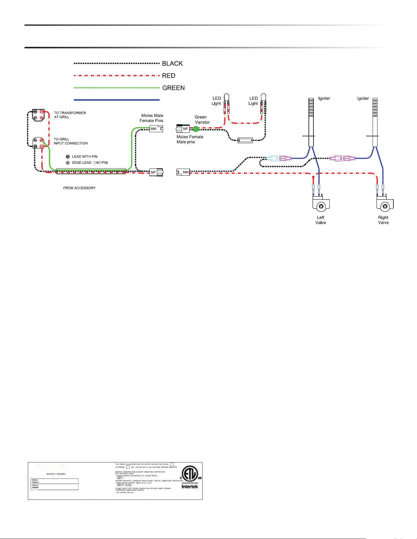
SCHEMATIC 19
CONTACTING CUSTOMER SERVICE 19
6
USING YOUR LYNX ACCESSORY
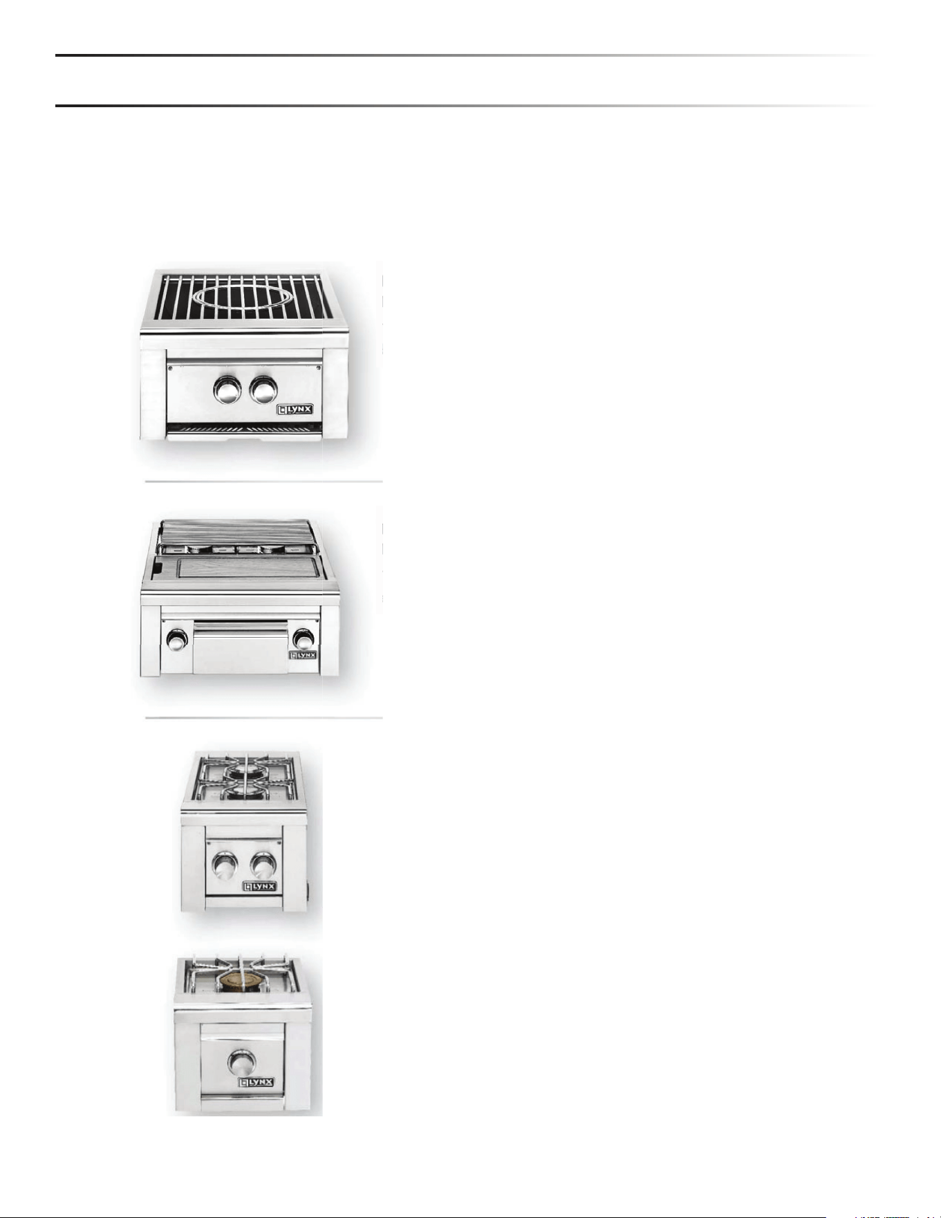
ACCESSORIES COVERED IN THIS MANUAL
This manual covers several Lynx accessory appliances and optional accessories for those appliances. Except where noted,
the assembly, installation and use of these Lynx accessories is identical.
POWER BURNER
MODEL LBP
The Lynx Power Burner is a dual-ring commercial style burner
with a range of 3,000 to 47,000 BTU's.
PREP CENTER
MODEL LSB2PC-1
The LSB2PC-1 Prep Center Features two 15,000 BTU burn ers and
an integral bamboo cutting board for food prep.
SIDE BURNER 1 & 2
MODELS LSB1-3 & LSB2-2
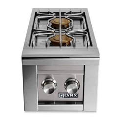
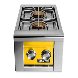
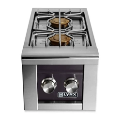
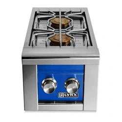
The LSB1-3 & LSB2-2 (Lynx Side Burner 1 & 2) features either
one or two 15,000 BTU burners for cooking smaller food items.
The LSB 1-3 and LSB2-2 are designed for installation in a non-
combustible, built-in enclosure.
7
BEFORE YOU START
IF SHIPMENT ARRIVED DAMAGED
WARNING
• Never install this product into a combustible enclosure. Doing so could result in fi re, property damage and personal
injury.
• Never locate the accessory under a roof or overhang, in a building, garage, shed or other such enclosed area.
• Always maintain the required clearances from combustibles as detailed. Accessories are designed for outdoor use
only. Never use in a garage, building, shed, breezeway, or other enclosed area. Do not use this equipment under any
unprotected overhead combustible construction.
• Installation must conform with local codes or, in the absence of local codes, with either the National Fuel Gas Code,
ANSI Z223.1/NFPA 54, or Natural Gas and propane Installation Code, CSA B149.1, or Propane Storage and Handling
Code, B 149.2, in Canada.
VISIBLE LOSS OR DAMAGE
CONCEALED LOSS OR DAMAGE
Be certain any visible damage to the carton
is noted on freight bill or express receipt and
signed by the person making delivery.
FILE CLAIM FOR DAMAGES IMMEDIATELY,
regardless of extent of damage.
If damage is unnoticed until the accessory is unpacked,
no tify the transportation company or carrier immediately
and fi le a "concealed damage" claim with them. This should
be done within (15) days of the date delivery is made to
you. Be sure to hold on to the container for inspection. We
cannot assume responsibility for damage or loss incurred
in transit. (See INDEX: "Obtaining Service from Lynx" for
further details.)
IMPORANT NOTES
WHERE’S THE WIND?
When selecting a suitable location, consider important
factors such as exposure to the wind and foot-tra c
patterns.
If you have a side burner attached to a freestanding grill,
position it so the prevailing wind blows into the front
control panel (at your back when grilling), supporting the
proper front-to-rear airfl ow.
Built-in accessories located in areas with prevailing winds
should be protected by a wind barrier.
HOW LONG IS YOUR RUN?
Keep all gas supply lines as short as possible because gas
lines lose pressure over distance and with each elbow and
tee that is added. This drop in pressure a ects accessory
performance. (See INDEX: "Gas Supply Line Runs" for
further details.)
ARE YOU ON THE LEVEL?
Proper leveling during installation is critical. An accessory
that is out of level will cause erratic burner combustion and
ine cient, uneven heating. A carpenter's spirit level should
be used to level the accessory both front-to-back and side-
to-side.
If the fl oor is uneven or has a decided slope, re-leveling may
be required each time you move a freestanding unit.

8
BEFORE YOU START (con’t)
BUILT-IN INSTALLATION
Lynx built-in accessories are intended for installation in a
built-in enclosure constructed of non-combustible materials.
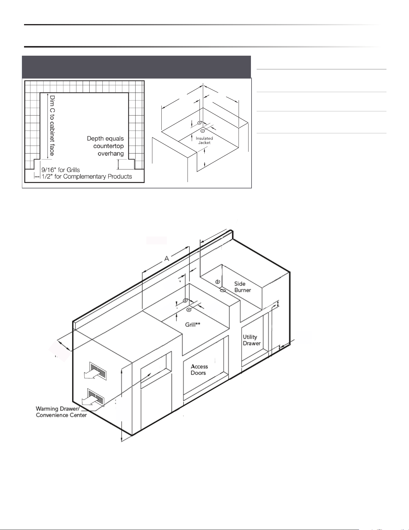
The accessory drops into the opening shown in the cutout
detail drawing and hangs from its counter-top trim. A deck is
not required to support it from the bottom.
Pay special attention to the provisions shown for gas line
hook-up. (See INDEX: "Cut-out Dimensions for Built-in Grills
& Accessories")
Installation provisions may be made for the Power Burner
installation. The Power Burner cooking height may be
reduced to better accommodate large cooking pots.
Clearances to combustible material must be maintained
as outlined below. No combustible material shall be used
in the construction of a counter top using a recessed
application.
The enclosure should have ventilation holes to prevent gas
build-up in the event of a leak. The deck ledges and counter
should be fl at and level.
For an enclosure having four sides, a top and a bottom:
1. At least two ventilation openings shall be provided in the
side walls of the enclosure, located within 5 in (217 mm)
of the top of the enclosure, equally sized, placed on two
adjacent sides, and unobstructed. The opening(s) shall
have a total free area of not less than 10 square inches for
each 20lb cylinder tank stored.
2. Ventilation opening(s) shall be provided at fl oor level
of the enclosure and shall have a total free area of not
less than 10 square inches for each 20lb cylinder tank.
If ventilation openings at fl oor level are in a side wall,
there shall be at least two openings. The bottom of the
openings shall be 1 in (25.4 mm) or less from the fl oor
level and the upper edge no more than 5 in (127 mm)
above the fl oor level. The openings shall be equally
sized, placed on two adjacent sides and unobstructed.
3. Every opening shall have minimum dimensions so as to
permit the entrance of a 1/8 in (3.2 mm) diameter rod.
CLEARANCE TO COMBUSTIBLE MATERIALS
Minimum clearance from the sides and back of the
accessory to adjacent combustible construction below the
countertop is 12" from the sides and back.
Degagement minimal entre /es parois laterales et l'arriere
de l'appariel et la construction combustible au-dessous du
panneau superieur de l'appareil (30 cm a partir des parois
laterales et 30 cm a partir de l'arriere).
Minimum clearance from sides and back of unit to adjacent
combustible construction extending above the counter top
is 18" from the sides and back.
Degagement horizontal minimal entre /es parois laterales
et l'arriere de l'appariel et la construction verticale
combustible au-dessus de l'appareil (45.7 cm a partir des
parois laterales et 45.7 cm a partir de l'arriere).
Do not use this appliance under unprotected overhead
combustible surfaces.
Ne pas utiliser cet appareil sous une surface combustible
non protegee.
9
SPECIFICATIONS & INSTALLATION
MODEL
A BC
LSB1-3 12.13
(30.8cm)
10.63
(27cm)
12.50
(31.7cm)
LSB2-2 12.13
(30.8cm)
10.63
(27cm)
24.50
(62.2cm)
LSB2PC-1 24.25
(61.6cm)
10.63
(27cm)
24.50
(62.2cm)
LPB 19.00
(48.3cm)
10.63
(27cm)
22.00
(55.9cm)
5”
(12.7 cm)
4.5”
(11.4 cm)
3”
(7.6 cm)
AA
B
C
COUNTER TOP NOTCH DETAIL
Only required if island counter top overhangs the face of the island
If building an island that does not conform to the standard properties listed in the following pages, please contact Lynx
Grills at 888-259-5969 to verify all safety requirements regarding installation have been met.
**1” (2.54 cm) square hole must be located at rear of grill
cutout.
120V GFI outlet must be located within 6” (15.2 cm) of the
1” hole.
3-1/4” min
3” min
3-1/2”
2”
2-1/4”
36-3/8”
min
8”
10
GAS CONNECTIONS
GAS PLUMBING
WARNING
Never connect a gas line directly to the accessory. A pressure regulator must be installed on all gas equipment.
The gas line can be teed o the regulator from the gas grill. If the accessory is not teed o the grill, it will require a
regulator. Removing or failing to install the pressure regulator can result in fi re and serious personal injury and will
void the warranty.
The accessory is factory set to use either propane (LP)
or natural gas (NAT). It is critical that the gas you use
matches that which the accessory was set up for. You can
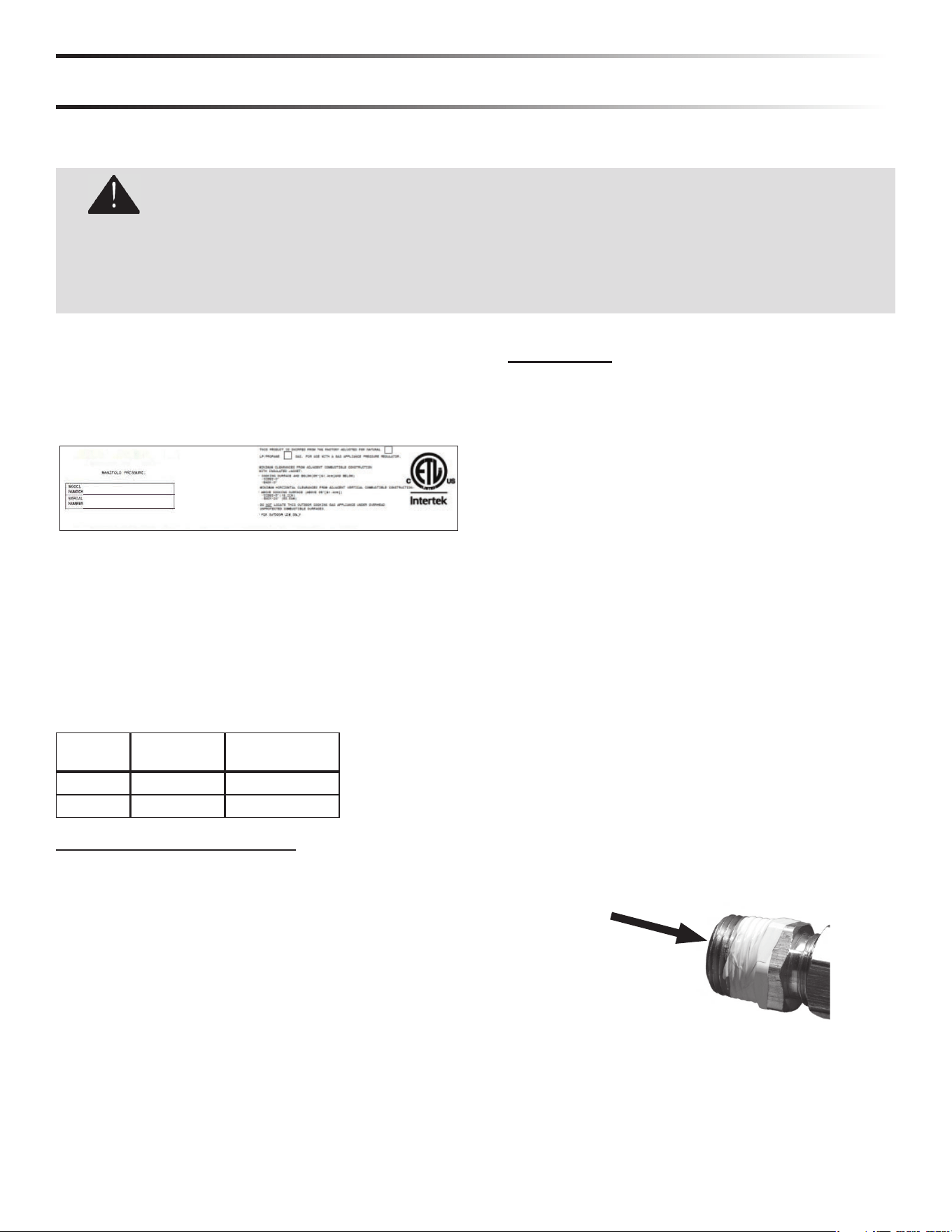
verify that by checking the rating plate.
LYNX GRILLS, LLC
Greenwood, Mississippi 38930
THIS DESIGN CERTIFIED UNDER ANSI Z21.58; CSA 1.6 OUTDOOR COOKING GAS APPLIANCE
NAT. 4” (996 Pa) LP/PROP 10” WCP (2492 Pa)
The rating plate is located on the heat shield behind the
front panel.
Ensure that the gas supplied meets with the minimum
pressure requirements.
Do not operate the accessory on any gas other than that
for which the accessory has been set.
Fuel WC Max Inlet WC Min Under
Full Load
Nat Gas 7 in 4 in
LP 14 in 11 in
WATER COLUMN REQUIREMENTS
Both the regulator (LPB models only) and the manifold
orifi ces have been tuned for the type of gas specifi ed on
the rating plate.
Converting to a di erent type of gas requires a
conversion kit which is purchased separately and must be
installed by a qualifi ed technician.
All installation and all installation parts must conform to
local codes with the National Electrical Code, ANSI/NFPA
70-1990 and the National Fuel Gas Code, ANSI Z223.1 /
NFPA 54 in the U.S. and CGA-B149.1/.2 in Canada.
Canadian installations must conform to CGA-B149.1/.2
natural gas/propane installation code. (Canada)
NATURAL GAS
Lynx recommends that only qualifi ed professionals
perform the required plumbing on this product.
The gas supply line must be sized to accommodate the
total BTU requirements of all the gas-fi red equipment
that will be connected to that line.
Everything after the shut o valve has to be ½” inside
diameter. Before the shut o valve is ¾” inside diameter
and might have to go to a bigger gas line, depending on
the length of the gas installation and BTU’s needed.
• Calculate the total BTU output of all equipment and
refer to the maximum runs for appliances. Failure to
meet these requirements may reduce performance of
the accessory and any other appliances running on
that supply line.
• Always keep supply line runs as short as possible.
Refer to the maximum runs for appliances
• A gas shut-o valve must be installed in an easily
accessible location by a qualifi ed plumber.
• Keep any threading compound o of the fi rst two pipe
threads to avoid having any small pieces of compound
break loose and clog a burner valve or orifi ce. Do not
put sealant on any male end of fl are fi ttings.
Keep last two
threads clean
For built-in installations, it is recommended that any
fl exible pipe used be kept as short as possible.
11
GAS CONNECTIONS (con’t)
LP GAS
LP cylinder with type 1 valve connection
If the accessory is not teed o the grill, it will require
a regulator either for the LP cylinder or permanently
plumbed LP connections, such as those in line with a bulk
cylinder.
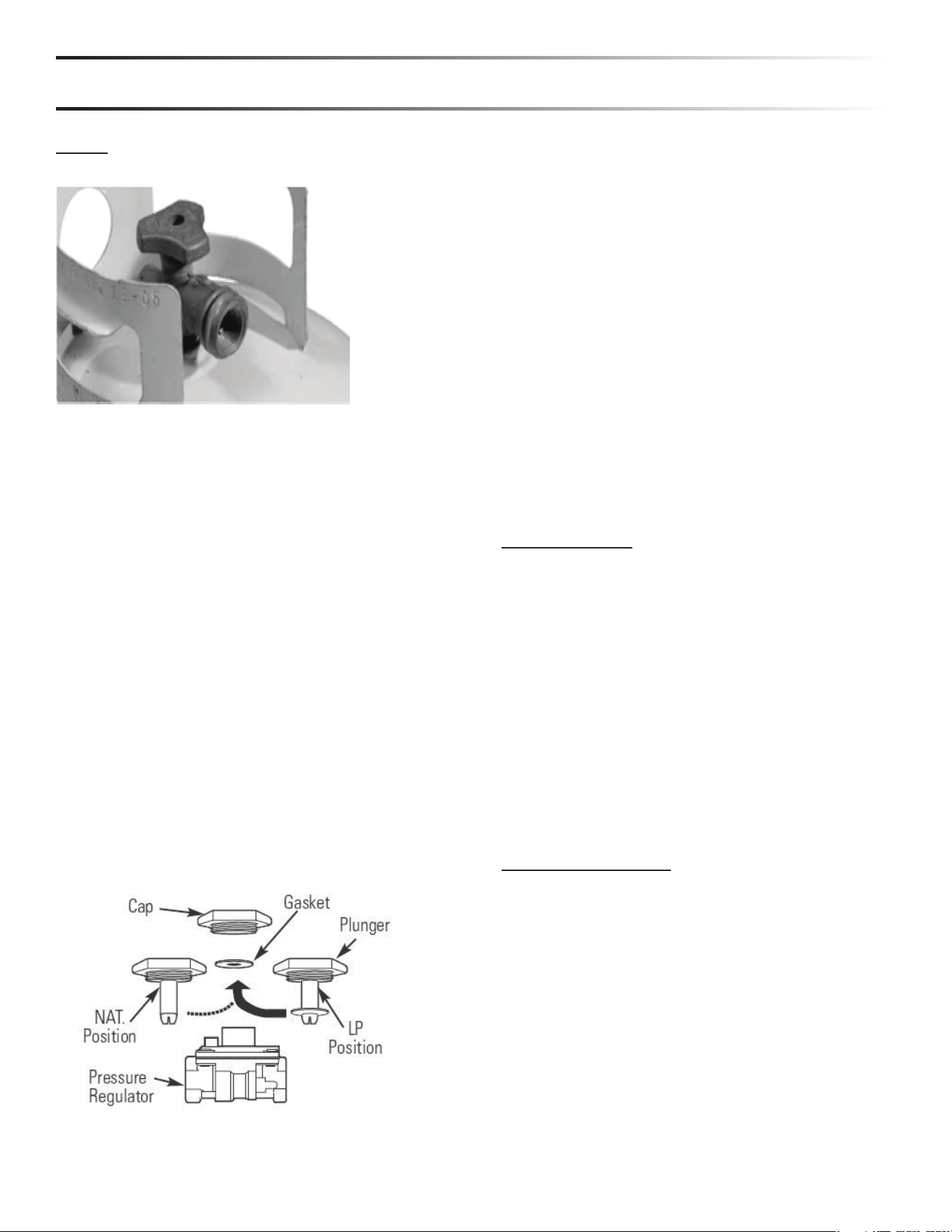
When using the 4/11 regulator you must ensure that it is
set for the proper fuel type. This is done by removing
the regulator cap and gasket and looking at the bottom
of the plunger to see what fuel type is visible. This is the
regulator fuel setting. NAT is for natural gas and LP is for
propane gas. The LP setting can be further identifi ed by
the large diameter disk on the bottom of the plunger. To
change from one gas to the other simply push the plunger
to the side to snap it out of the cap, turn the plunger so
it reads the desired gas type on the bottom, and push
the plunger until it snaps back into place in the cap then
replace the cap into the regulator.
When exchanging your cylinder for a refi ll, exchange
only for a Type 1 2016 cylinder with an over-fi ll protection
device.
Never use a cylinder with a damaged valve.
A dented or rusty LP cylinder may be hazardous and
should be avoided. If in doubt, have it checked by your LP
supplier.
Always check for leaks after every LP cylinder change.
Always shut o the LP-gas supply at the cylinder when
the accessory is not in use.
Cylinders must be stored outdoors in a well-ventilated
area out of the reach of children. If your accessory is
stored indoors, the LP cylinder must be stored outside.
LP CONNECTIONS
Make sure the LP cylinder valve is fully closed. It is
possible for the valve to be open without releasing gas
but, as soon as you start connecting the regulator, gas will
leak from the connection.
Insert the regulator inlet into the cylinder valve and turn
the black coupler clockwise until the coupler is hand tight.
Do not over-tighten this connection.
To disconnect the coupler, fi rst make sure the main
cylinder valve is turned o . Grasp the coupler and turn
counter clockwise. Always leak-test the connection after
refi lling or exchanging LP cylinders.
GAS CONVERSION KITS
Gas conversion kits are available from Lynx Grills to
allow the burner accessory to operate on either Natural
Gas or LPG. These kits should be installed by a qualifi ed
technician.
12
GAS CONNECTIONS (con’t)
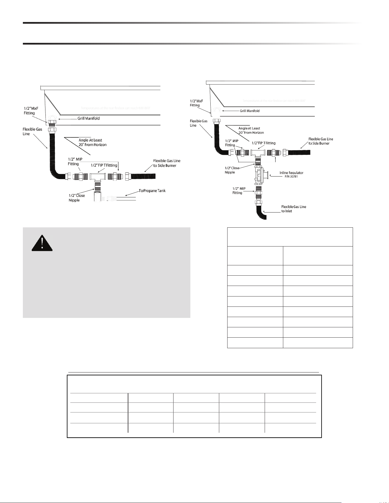
SUGGESTED GAS CONNECTIONS TO A LYNX GRILL
WARNING
CO
LD WEATHER WARNING: PR
O
PANE
Extremel
y
cold temperatures ma
y
cause
y
our burner to
light insid
e
the burner instead o
f
o
utsid
e
. Once lit, i
f
you
hear a ‘whooshing’ sound, immediatel
y
turn the burner
knob o
to extinguish the
ame and then immediatel
y
re-light the burner
.
MAXIMUM RUNS FOR ALL
APPLIANCES ON SUPPLY LINE
Run Length 3/4”
Pipe (in feet)
Max BTU for all
Appliances on line
10 360,000
20 245,000
30 198,000
40 169,000
50 150,000
60 135,000
70 123,000
80 115,000
MODEL
INNER
BURNER
OUTER
BURNER
OPEN TOP
BURNER
TOTAL INPUT
LPB 13,000 34,000 47,000 BTU/Hr
LSB2PC 2 @ 15,000 30,000 BTU/Hr
LSB1-3 1 @ 15,000 15,000 BTU/Hr
LSB2-2 2 @ 15,000 30,000 BTU/Hr
MODEL-SPECIFIC BTU OUTPUTS
PROPANE NATURAL
13
ELECTRIC CONNECTIONS
OPTIONAL ELECTRICAL KITS
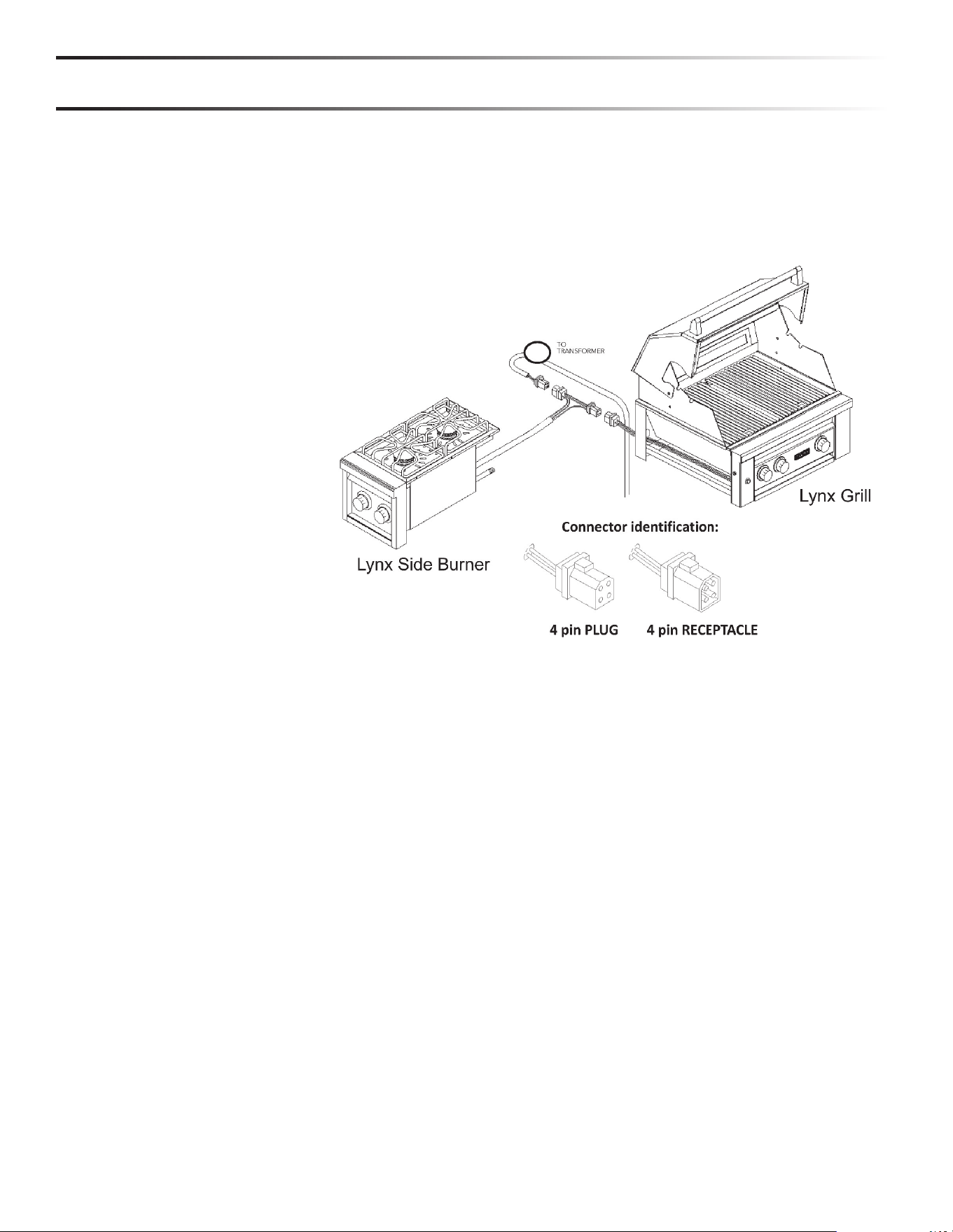
Each accessory includes 6 feet of wiring (coiled inside the back of the accessory) to connect the accessory to a Lynx grill.
Additionally, Lynx manufactures 2 specialized electrical kits that you may purchase for your accessory, depending upon how
it will be installed. Each electrical kit ships with an instructional sheet for assembly. Assembly instructions and schematics/
drawings can also be found on our website at www.lynxgrills.com.
LASK Lynx Accessory Switch Kit
LPEK Lynx Power Extension Kit
This switch and transformer kit allows independent control of a Lynx accessory
burner without connection to a grill. The kit contains a transformer and mounting
bracket as well as a switch assembly with a mounting plate.
Lynx Power Extension Kit provides 12 feet of additional wire between your Lynx Grill
and accessory burner.
The accessory electrical harnesses are designed to
provide power for both ignition and lighting. While ignition
is controlled at the accessory, lighting is controlled at the
grill.
You can control lighting at the accessory by installing the
Lynx Accessory Light Switch (LASK).
Disconnect the 4-pin connector on the grill and connect
those plugs to the mating plugs on your accessory. (See
Index "Electrical Connections)
Important note: If using multiple Lynx accessories with
the Control Illumination/Blue LED'S, a connector for this
purpose is built into the accessory wiring. This will allow
you to use the light switch on your Lynx grill to actuate the
power on more than one accessory.
Installation requires an outdoor 120VAC 15A GFI (Ground
Fault Interrupter) electrical outlet adjacent to the
accessory.
The GFI outlet features an internal breaker that reduces
shock hazard. This type of outlet should be installed by a
qualifi ed electrician either inside the island enclosure for
built-in units, or near the location where a free-standing
unit will be used.
For built-in accessories, the supplied 12V transformer is
connected to the accessory during installation.
If the electrical system fails to operate, a connection may
have come loose in shipping or the GFI may have tripped,
requiring a reset.
The grill accessory does not come with its own power source. It may be powered directly from your Lynx Grill.
When a Lynx grill is not available or if the grill is not located close enough to the accessory a Lynx LASK (Lynx Accessory
Switch Kit) is available as an optional purchase.
14
CHECKLIST BEFORE EACH USE (FOR YOUR SAFETY)
• Do you smell gas? If yes, shut o everything and call the
gas company or a qualifi ed plumber to check for leaks,
if not please continue.
• Are you prepared to stay with the side burner during
the entire cooking process? If not, gather what you
need be fore starting the lighting process. If yes, please
continue.
• Is your cooking area free and clear of any combustibles,
besides your food, that might ignite? If no, clear the
area before starting the lighting process, If yes, please
con tinue.
• Do all control knobs turn freely? If not, call for service; if
yes, please continue.
• If you are using a portable propane cylinder, is it
connect ed and leak tested? If not, check the connection
before continuing. If yes please continue.
• Do you know where your side burner's main gas supply
shut-o valve is located? If not, locate it before continu-
ing. If yes, please continue.
• Are all burners properly seated in the side burner? If
not, seat the burners properly before continuing. If yes
please continue.
• Is the wind blowing just lightly and not blowing on the
side burner? If not, wait until the wind subsides or turn
your free-standing grill so the wind goes into the front
of the grill. If yes, please continue with the lighting
process.
MESSAGE TO OUR CUSTOMERS
You've just joined the world of Lynx cooks ... a discriminating collection of
amateur and professional chefs that take outdoor cooking to a new level.
Lynx manufactures many accessory cooking appliances to compliment your
Lynx grill and your desire for truly superior cooking results.
Your appliance has been designed and built with meticulous attention to
detail and it o ers some unique and powerful features. You can achieve
maximum performance and enjoyment of these features only by carefully
reading this manual ... before your fi rst cook-out. This manual includes
important safety tips and great hints for better grilling. You should keep it
handy for easy reference.
Also, at Lynx, we enjoy hearing from our customers. We like to hear about
your successes but also about any di culties you are having. Please feel free
to contact us with any questions or problems, or just to share a new recipe.
Please include the model number of your appliance in your correspondence.
With the proper use and care this product will provide years of trouble-free
service.
Should your Lynx appliance change ownership, please make
sure that the new owner receives this manual.

15
IMPORTANT SAFETY PRECAUTIONS
PLEASE REVIEW THESE IMPORTANT SAFETY PRECAUTIONS BEFORE YOU USE YOUR GRILL
ACCESSORY.
1. NEVER LEAVE THE GRILL ACCESSORY UNATTENDED
WHILE COOKING.
2. Ensure all tie-down wires have been removed from the
burners, and any burner caps have been removed from
the box inside the accessory.
3. Always use caution when operating the grill accessory in
a windy area. (See INDEX: "Where's the Wind" for further
details.)
4. Avoid wearing loose-fi tting garments or long sleeves
while grilling. They could ignite.
5. Never touch the grill accessory racks or immediate
surrounding metal surfaces with your bare hands while
grilling.
6. Use an insulated glove or mitt when opening and
operating the grill accessory.
7. The grill accessory covers must be fully removed or
opened while lighting the grill accessory. Releasing fuel
into a closed grill accessory before lighting will not make
it light sooner or more e ciently. It will only risk explosion
and personal injury or death. Never lean over hot grill
accessory surface or look directly into the grill accessory
when attempting to light.
8. Do not heat unopened food containers as pressure build-
up will cause the container to explode.
9. Do not use aluminum foil to line grill accessory racks or
drip pans . This will alter the airfl ow or trap exces sive
heat in the control area and can melt knobs and ignition
modules . Such damage is specifi cally excluded from
your warranty.
10. Never use charcoal or any other solid fuel in the grill
accessory.
11. Cooking excessively fatty meats and oils will cause fl are
ups . Internal fi res or damage caused by them or by
the grill accessory being left unattended while cooking
are not covered under the terms and conditions of our
warranty.
12. Never cook without a drip pan in place if your accessory
utilizes a built-in drip pan. Always ensure the drip pan
is pushed all the way to the back of the grill accessory.
When not correctly in place, hot grease can leak down-
ward and produce a fi re or explosion.
13. Grease is extremely fl ammable. Let hot grease cool
down before attempting to handle or dispose of it. The
drip tray should be cleaned of grease on a regular basis.
14. Do not use the grill accessory unless a leak check has
been performed on all gas connections. (See INDEX:
“Leak Testing” for further details.)
15. Never operate the grill accessory while under the infl u-
ence of alcohol or drugs.
16. Do not lean on side shelves and never place a load
weighing more than 25 pounds on a side shelf.
17. If any burner does not light or goes out during opera tion,
turn o all gas control knobs and wait fi ve (5) minutes
before attempting to re-light.
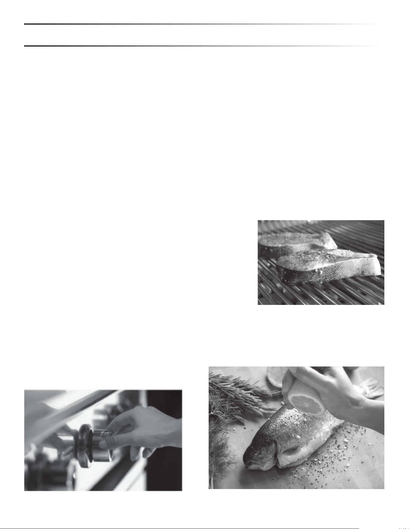
HOW TO LIGHT YOUR GRILL ACCESSORY
1. Before each use, complete the checklist below.
2. Make sure all burner control knobs are in the "OFF" position.
3. Push and hold the control knob for 2-5 seconds, allowing the igniter to heat up.
4. Turn the knob to the "LITE" position.
5. After ignition set the knob to the desired setting.
16
USING THE POWER BURNER (LPB)
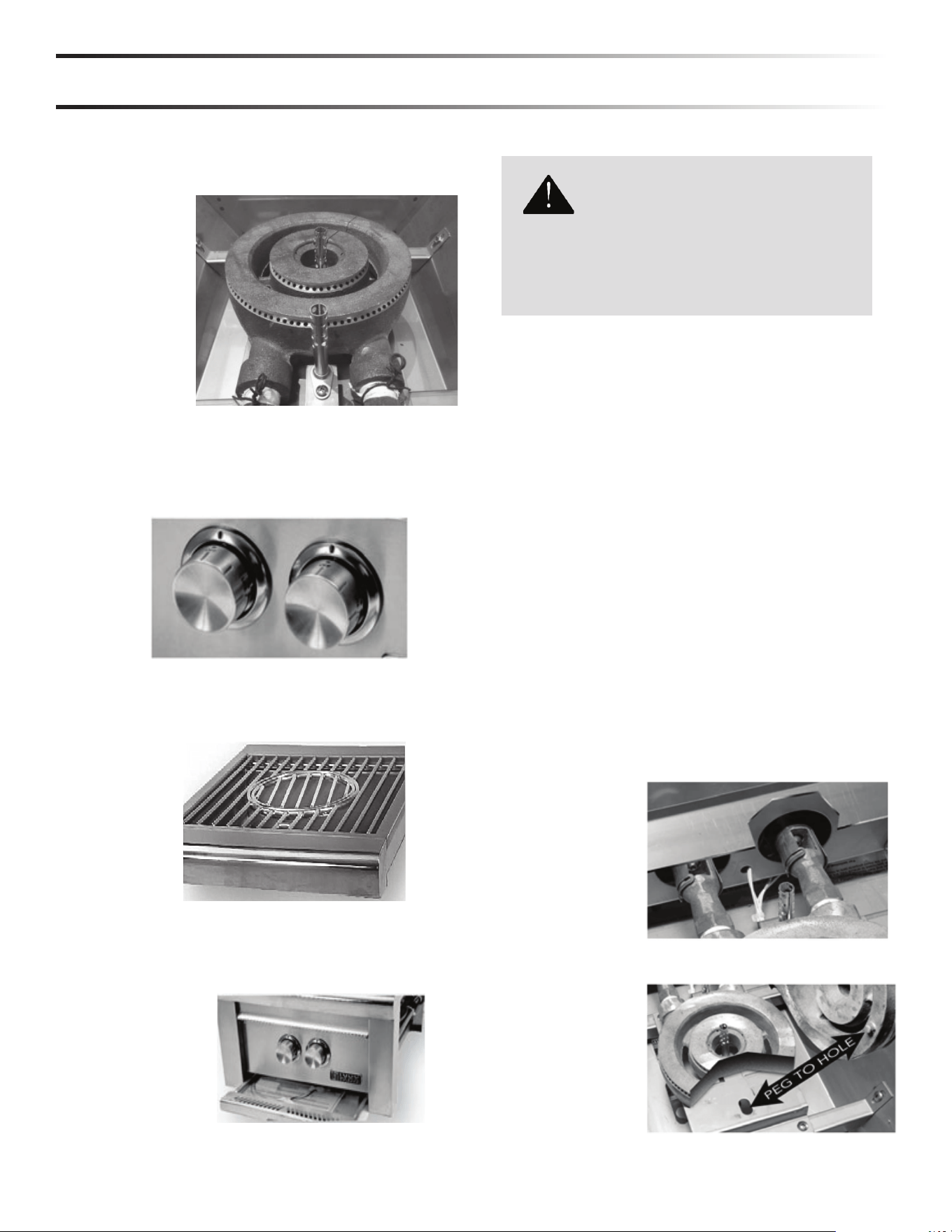
The Lynx Power Burner incorporates a cast brass, dual
ring, burner. Each ring can be independently operated for
maximum heat control. Used together they can generate
up to 47,000 BTU’s.
The knob on the left controls the outer burner ring and
the knob on the right controls the inner burner ring.
The Hot Surface ignition system provides reliable ignition.
The Hot Surface ignition system provides reliable ignition.
The main grate can easily handle oversized stock
pots and removing the center grate accommodates
a commercial style round-bottom wok base (12 inch
minimum).
The Lynx Power Burner also features a fully extendable
stain less steel drip pan.
SMELL OF GAS WHILE COOKING
YELLOW FLAMES
WARNING
IF YOU SMELL GAS WHILE THE GRILL
ACCESSORY IS OPERATING, IMMEDIATELY TURN
OFF ALL BURNERS AND SHUT OFF THE MAIN
FUEL SUPPLY.
• Perform a leak test (See INDEX: "Leak Testing" for
further details.)
• Check for blockages.
A yellow fl ame on the main burners indicates a lack of air.
But, if the air around the grill is dusty or if heavy grease
is present, some orange tips on the burner fl ame are
normal.
ADJUST THE AIR SHUTTER
ONLY DO THIS WHEN THE ACCESSORY HAS COOLED
DOWN COMPLETELY! Make sure all grill controls are in
the "OFF" position.
3. Ensure that the
burner is seated
correctly on
the frame, with
the brass peg
seated inside the
positioning hole.
4. Re-light and
check the fl ame.
1. Remove the cooking grates.
2. Reach under the drip guard and rotate the air shutters
to adjust.
17
LIGHTING INSTRUCTIONS
SAFETY PRACTICES AND PRECAUTIONS
WARNING
Read the ‘User Manual/Installation Instructions carefully
and completely before using your grill or grill accessory
to reduce the risk of fi re, burn hazard or other injury.
Ensure that burner ties and all packing materials are
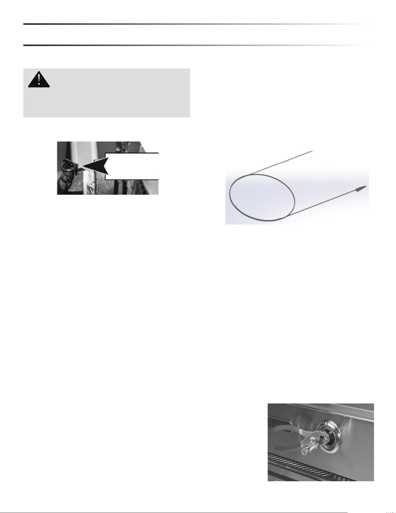
removed before lighting any new accessory.
REMOVE ALL
SHIPPING TIES
AT EACH NEW SEASON
At the start of each new grilling season you should
remove the cooking grates and check the burners,
venturis, orifi ces and valves for obstructions.
Spiders and insects often nest in these areas of the
acces sory and can disrupt air fl ow, causing damage to the
acces sory and personal injury.
Also, check all hoses and fi ttings for damage, abrasion,
wear and tear and repair, if necessary, before turning the
gas on.
For LPB models, replacement pressure regulators and
hose assemblies, must be the type specifi ed by Lynx.
The pressure regulator and hose assembly supplied
with the unit must be used. If the unit is LP, screw the
regulator into the tank and leak check the hose and
regulator connections with a soap and water solution
before operating the burner. Turn all knobs to OFF then
SLOWLY turn on the gas supply valve. Do not use any
grill accessory if you smell gas.
PURGING THE GAS LINES
You should purge the gas line of air before attempting to
light the grill accessory.
1. Make sure all grill controls are in the "OFF" position.
2. Slowly turn on the main gas supply.
3. Push in the control knob for the burner furthest from
the fuel source. Using the burner furthest from the
fuel source will completely purge the lines. It will take
several seconds for the burner to light.
4. Hold the knob ON for about 20 seconds to allow the
air in the system to purge and the burner to light
5. Wait at least 5 minutes after shutting o the control
before attempting to light the burners.
MATCH LIGHTING
If a burner fails to light after several attempts, it can be
match lit. If you've just attempted to light the burner with
the igniter, allow 5 minutes for any accumulated gas to
dis sipate before match lighting.
Make sure all knobs are in the OFF position. Keep your
face as far away from the burner as possible. Side burners
can be lit by passing a lit match over the port of the
burner. The power burner requires the use of a lighting
rod with a lit match which is located in the drip tray.
LOW HEAT FLAME ADJUSTMENT
The burners on your Lynx accessory feature an adjustable
low setting. Fluctuations in gas pressure, gas conversion
and even in the quality of the gas itself may a ect burner
performance at the "LOW" or “MED” setting. It could be
either too high or too low causing the fl ame to turn o .
To adjust the burner setting:
1. Make sure the grill accessory is cool.
2. Remove the grates so that you can see the fl ame while
adjusting the burner.
3. Light the burner and set it to "LOW". (all the way
counter- clockwise).
4. Pull o the control knob.
5. While holding the valve shaft with pliers, insert a thin
fl at-blade
screwdriver
into the shaft
and, while
watching
the fl ame,
adjust it to
a minimum
stable
setting.
While holding the lit match next to the burner port, push
and turn the control knob of the burner to ‘Lite”. If the
burner does not light in 4 seconds, turn the knob o and
wait 5 minutes before attempting again.
18
STAINLESS STEEL
Our products are known for their attractive appearance. We
achieve this by selecting only the fi nest grades of stainless
steel and applying exacting workmanship.
In order to maintain this attractive appearance over the life of
the grill it is important to take the following steps:
• After each use wipe down the exterior to remove grease
and splatters.
• Be sure to follow the cleaning instructions for keeping the
grates and burners clean and ready for use.
• Use a commercially available Stainless Steel cleaner to
clean and polish the exterior surfaces.
Doing these things on a regular basis minimizes the amount
of e ort required.
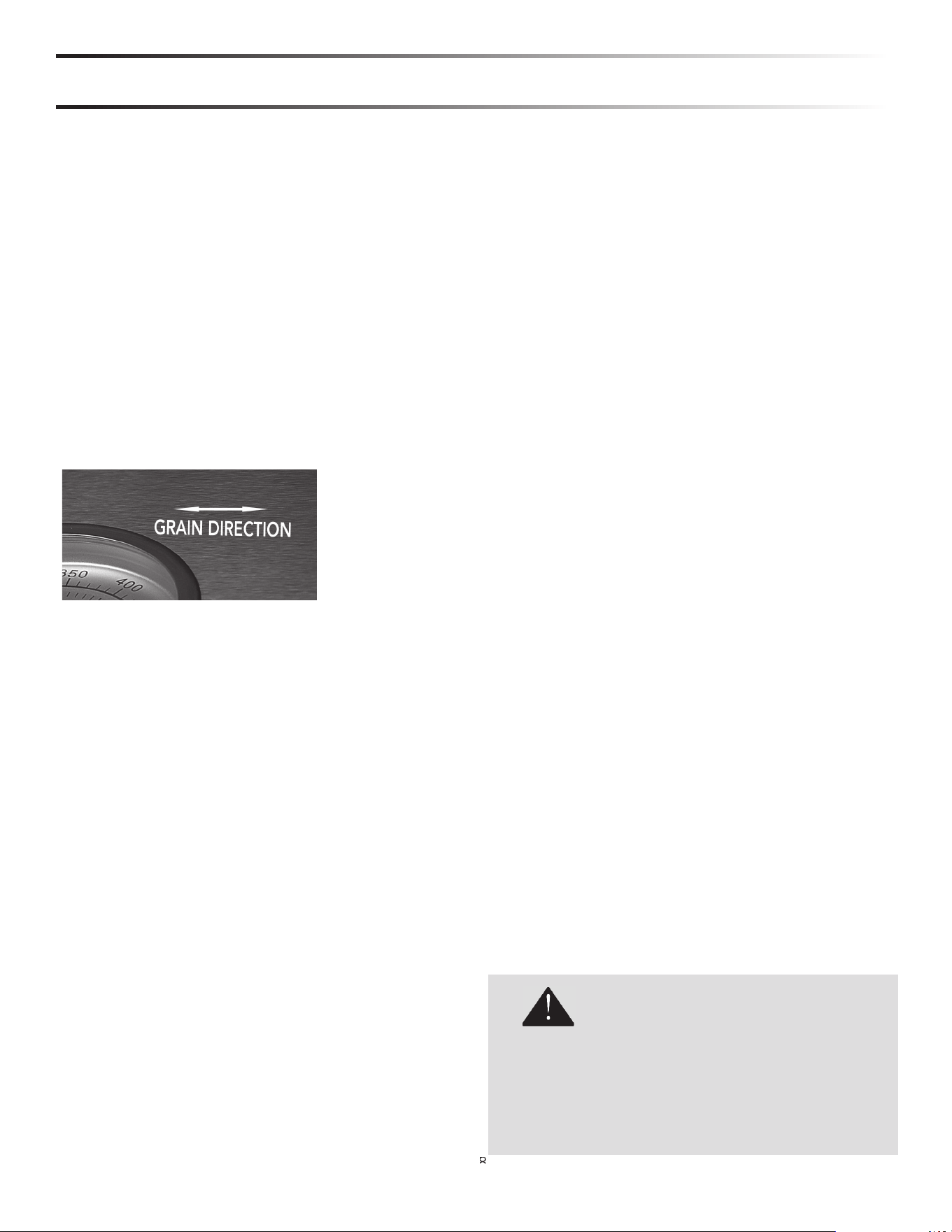
Part of the appeal of the exterior is the fi ne grain fi nish. When
removing stubborn stains:
• Do not use metallic abrasives and always rub in the direc-
tion of the grain.
• Some household cleaning products are not suitable for
stainless steel; be sure to read the label before using on
your Grill.
• Always use the mildest cleaning solution fi rst, scrubbing in
the direction of the grain. Specks of grease may gather in
the grain of the stainless steel and bake on to the surface,
giving the appearance of rust.
To remove these baked-on foods use a fi ne to medium
grit non-metallic abrasive pad (Scotch Brite is good) in
conjunction with a stainless steel cleaner.
• Solutions used for cleaning concrete and masonry can be
very corrosive and will ‘attack’ stainless steel. Ensure your
products are well protected before you allow the use of
such chemicals near your grill.
SPECIAL NOTE FOR LOCATIONS NEAR POOLS AND
COASTAL AREAS:
The 304 stainless steel material used in the construction
of the unit is highly rust resistant, however, chlorine in the
air from swimming pools or the salt from sea air may cause
surface rust to appear and even create some pitting if left on
the product.
Here are a few tips to avoid this:
• Regularly wipe down the exterior surfaces with a damp
cloth. (Micro fi ber cloths perform very well).
• Allow the surfaces to dry before installing the cover. Do not
cover a damp grill.
• For seasonal storage use the product referred to above,
ensure the grill is dry and then cover and secure the cover
to minimize the amount of damp air getting to the surfaces.
After your fi rst use certain areas may discolor from the
intense heat given o by the burners - this is normal and
cannot be cleaned o .
For light and heavy food stains there are many di erent
stainless steel cleaners available.
DRIP TRAY
The drip tray should be cleaned after each use. After the grill
is completely cool, remove the drip tray by pulling it out until
it stops, then lifting the front edge until the drip tray comes
free.
Clean it with hot soapy water or an oven-style cleaning
product and re-install. When using an oven-style cleaning
product be sure to carefully follow the manufacturer’s
instructions. Many of these cleaners are toxic and can
damage the stainless steel fi nish if not used properly.
Also, check the tray after rain. If you’ve left the grill
uncovered, you may need to remove the drip tray drain
plug to drain the water from the tray. The drain plug can be
removed with a fl at-head screwdriver.
C
LEANIN
G
Y
O
UR A
CC
ESS
O
RY BURNER
8
8
8
8
8
8
8
8
8
8
8
8
8
8
DO NOT ALLOW EXCESS GREASE OR LIQUIDS TO
ACCUMULATE IN THE DRIP TRAY AS THIS MAY
CREATE A FIRE HAZARD.
NEVER USE GRILL WITHOUT DRIP TRAY PROPERLY
INSTALLED.
WARNING
PAINTED PARTS
Wash with warm soapy water. DO NOT use steel wool,
abrasive cleaners, ammonia, or cleaners containing acid.
This may damage the fi nish.
19
CONTACTING CUSTOMER CARE
If service is required, call your authorized service agency.
Have the following information readily available.
• Model number
• Serial number
• Date purchased
• Name of dealer from whom purchased
Clearly describe the problem that you are having. If you
are unable to obtain the name of an authorized service
agency, or if you continue to have service problems,
contact LYNX Grills, Inc at 1-888-289-5969 or write to:
Lynx Grills, Inc
62201 Hwy 8 W
Greenwood, MS 38930
Record the following information indicated below. You will
need it if service is ever required. The serial number and
model number can be located either on the underside of
the drip tray (if you have one), on the heat shield behind
the front panel, or on the inside left panel wall.
Record the information indicated below. You will need it if
service is ever required.
Model number ________________________________
Serial number ________________________________
Date of purchase ______________________________
Date installed ________________________________
Dealer’s name _______________________________
Dealer's Address ______________________________
____________________________________________
If service requires installation of parts, use only authorized
parts to ensure protection under the warranty.
KEEP THIS MANUAL FOR FUTURE REFERENCE.
LYNX GRILLS, LLC
Greenwood, Mississippi 38930
THIS DESIGN CERTIFIED UNDER ANSI Z21.58; CSA 1.6 OUTDOOR COOKING GAS APPLIANCE
NAT. 4” (996 Pa) LP/PROP 10” WCP (2492 Pa)
SCHEMATIC
WHITE

Lynx Grills, Inc
62201 Hwy 82 West
Greenwood, Mississippi 38930 USA
888-289-5969
www.lynxgrills.com
33487 REV F
(050124