APZC-SDR01
www.zifisense.com
I
APZC-SDR01 User Manual

APZC-SDR01
www.zifisense.com
II
Copyright Statement
ZiFiSense owns the copyright on this specification. No part of this
specification may be reproduced in any form or means, without the prior
written consent of ZiFiSense.
Disclaimer
This specification is preliminary and is subject to change at any time
without prior notice. ZiFiSense assumes no responsibility for any errors
contained herein. ZiFiSense is not responsible for any patent infringement
of third party on its use or as a result of its uses. Other products/services
not certified by the patent license, shall be deemed within patent
ownership of ZiFiSense.

APZC-SDR01
www.zifisense.com
III
Content
1 Abstract ......................................................................................................................................... - 1 -
2 Product Description .....................................................................................................................- 1 -
2.1 Product Overview ................................................................................................................- 1 -
2.2 Interfaces ............................................................................................................................. - 2 -
2.3 Specification ........................................................................................................................- 3 -
3 Quick Guide ................................................................................................................................. - 4 -
3.1 Quick start installation diagram .......................................................................................... - 4 -
3.2 Quick procedure .................................................................................................................. - 4 -
3.2.1 Platform account ...................................................................................................- 4 -
3.2.2 Log in/out ............................................................................................................... - 4 -
3.2.3 Initial power-up ......................................................................................................- 4 -
3.3 RS485/232 interface definition ........................................................................................... - 6 -
4 Device Installation .......................................................................................................................- 7 -
4.1 Installation Note .................................................................................................................. - 7 -
4.1.1 Installation Environment ..................................................................................................- 7 -
4.1.2 Relocation Safety ................................................................................................. - 7 -
4.1.3 Electrical Safety .................................................................................................... - 7 -
4.2 Pre-installation preparation ................................................................................................. - 8 -
4.2.1 Inventory of device and accessories ................................................................. - 8 -
4.2.2 Provide your own installation tools .................................................................... - 9 -
4.3 Installation steps ................................................................................................................- 10 -
4.3.1 Step1:Main body mounting ............................................................................ - 10 -
4.3.2 Step2: ZETA Antenna Installation .....................................................................- 11 -
4.3.3 Step3: 4G antenna / network cable installation ............................................. - 13 -
4.3.4 Step4: Power supply installation ...................................................................... - 14 -
4.3.5 Step5: Gateway Grounding ...............................................................................- 16 -
4.3.6 Step6: Dust cap waterproof .............................................................................. - 17 -
5 FAQ ............................................................................................................................................. - 18 -
APZC-SDR01
www.zifisense.com
- 1 -
1 Abstract
This document applies to the ZETA Outdoor SDR Gateway (Model: APZC-SDR01)
instructional use. This document serves as a maintenance instruction document for the
Gateway and is used to instruct field personnel how to install and use the Gateway.
2 Product Description
2.1 Product Overview
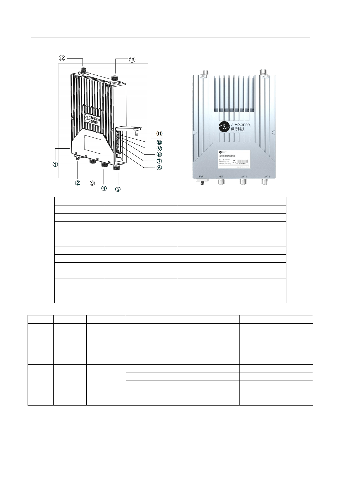
Built-in Adv-MFSK® modulation method, supports high-capacity concurrency, good
scalability, high flexibility, and adaptable rate, and carries the ZETA-C
®
protocol, which can
be applied to fast and frequent downlink polling scenarios;The gateway supports RS485 or
RS232 interface, which is compatible with scenarios of electric power Internet of Things.
APZC-SDR01
www.zifisense.com
- 2 -
2.2 Interfaces
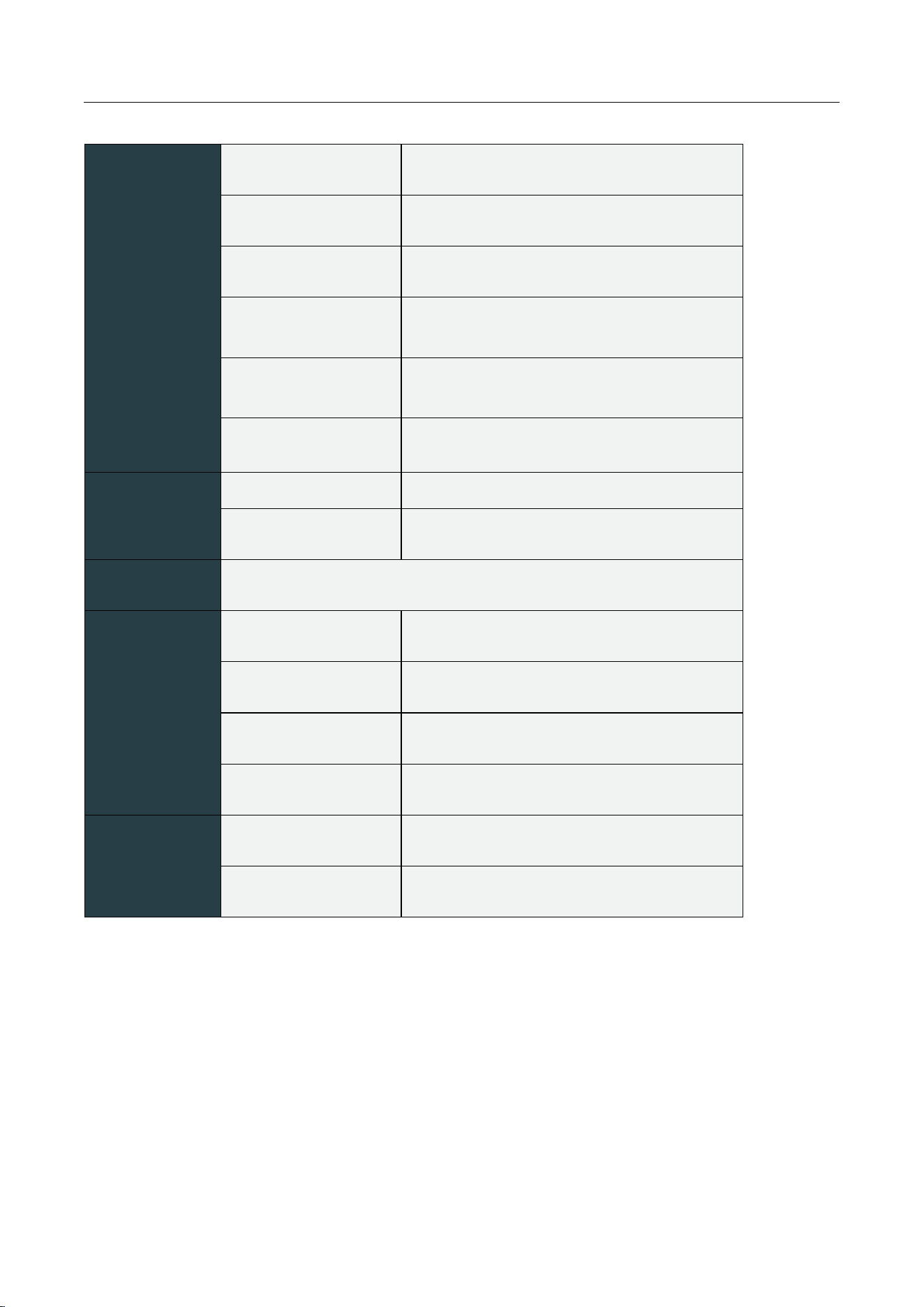
No.
Name
Description
1
Ground
Connect to Ground
2
Power
Power and network data interface
3
NET
4G Antenna Port
4
ANT1
ZETA RF Antenna 1
5
ANT2
ZETA RF Antenna 2
6
Debug Port
USB Debug Port
7
SIM
SIM Card Slot
8-11
LED Light
RF/NET/RUN/PWR
Status Indicator
9
LED Light
Network Status Indicator
12
Data Port
RS485 or RS232
13
ANT3
ZETA RF Antenna 3
No.
LED
Colour
State
Status
⑪
PWR
Red
Normal power supply
Light on
Power supply abnormal
Light off
⑩
RUN
Green
Normal Operation
Flash (200ms)
Abnormal operation
Light on
Upgrading
Flash (1s)
⑨
NET
Green
Good signal
Flash (200ms)
Weak signal
Light on
Network connecting
Flash (1s)
⑧
RF
Green
RF operates normally
Flash (200ms)
Abnormal RF operation
Light off
APZC-SDR01
www.zifisense.com
- 3 -
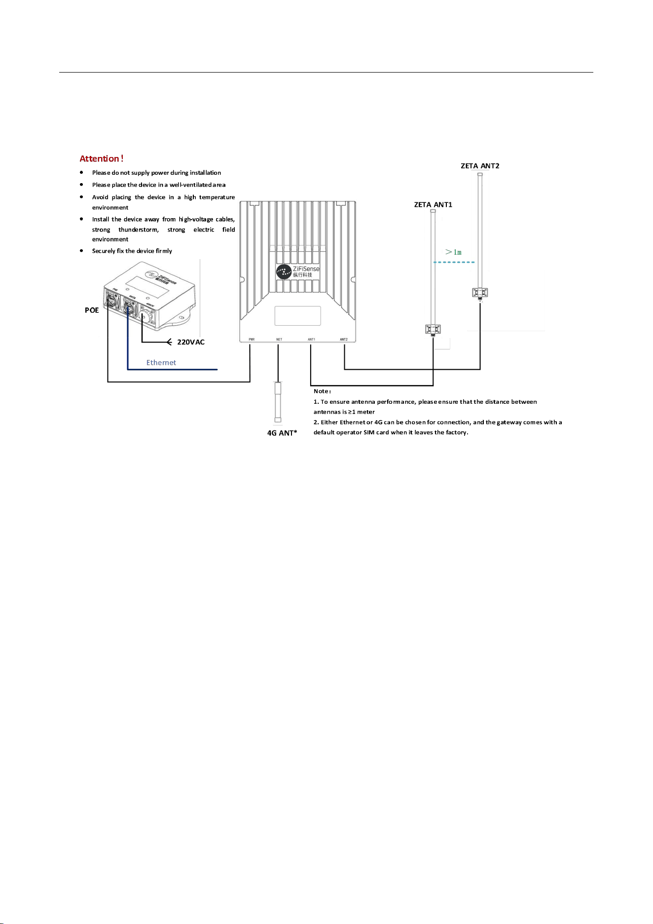
2.3 Specification
Wireless
Protocol
ZETA-C & ZETA-P/ZETA-S Dual-mode
Support Frequency
920-925MHz/863-870MHz
Modulation
Adv-MFSK
®
Tx Power
≤20dBm@920MHz
≤
14dBm@868MHz
Sensitivity
-122
±
2dBm@8kbps
-130dBm±2dBm@300bps
Antenna
1.75/0.8m FRP Antenna
1*4G Antenna
Electrics
Power supply
POE / 220VAC /±48VDC
Power
≤15W
Function
Supports noise scanning, remote OTA
Physical
Features
Size
225*180*42mm
Material
ADC12 Alloy
Installation
Pole Clamp, Nail Wall
Protection
IP66
Environment
Operate temp
-20
℃
~55
℃
Storage temp
-40
℃
~75
℃
APZC-SDR01
www.zifisense.com
- 4 -
3 Quick Guide
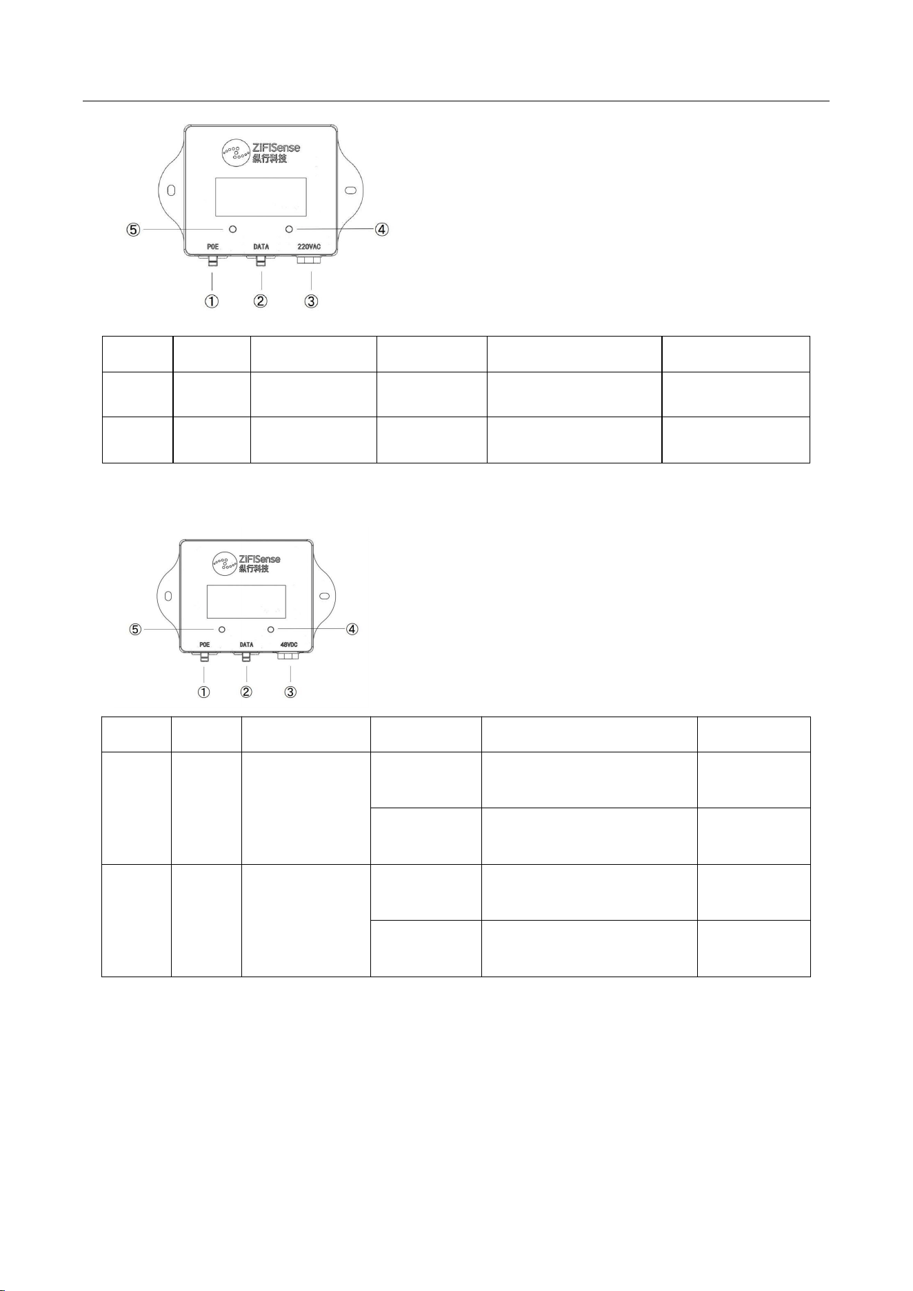
3.1 Quick start installation diagram
3.2 Quick procedure
3.2.1 Platform account
Platform account is assigned by ZiFiSense for customers without registration, please
contact technical support to get it.
3.2.2 Log in/out
Enter the ZETAManagement Platform URL in your browser and enter your username,
password and verification code on the login screen.
3.2.3 Initial power-up
The gateway is powered on when it is connected to the power supply. At this time, you
can check whether the status of the device is normal through the power indicator, and the
power supply provides 220V AC or 48V DC adapter, each of which is described below.
220V AC Power indicator
APZC-SDR01
www.zifisense.com
- 5 -
No.
LED
Indicator
Color
Description
Status
④
INPUT
Power input
indicator
Yellow
Input power supply is
normal
Always bright
⑤
OUTUT
Power output
indicator
Red
Input power supply is
normal
Always bright
48V DC Power indicator
No.
LED
LED
Indicator
Color
Description
④
INPUT
Power input
indicator
Red
Input power supply is
normal (power cord positive
connection)
Always bright
Green
Input power supply is
normal (power cord is
reversed)
Always bright
⑤
OUTU
T
Power input
indicator
Red
Output power supply is
normal (power cord positive
connection)
Always bright
Green
Output power supply is
normal (power cord is
reversed)
Always bright
After the device is powered on, the device operation status can also be checked through
the Power/Master/Network Connection/Antenna Operation indicator. Among them, the
device status indicator is described as follows.
Note: The status indicator is on the side of the gateway, you need to open the
cover, if not open the cover please login to the platform directly to check the status.
①Power output + data interface
②Network data interface
③Power input interface
④Power input indicator
⑤Power output indicator
①Power output + data interface
②Network data interface
③Power input interface
④Power input indicator
⑤Power output indicator
APZC-SDR01
www.zifisense.com
- 6 -
No.
LED
LED
Indicator
Color
Description
1
PWR
Power
indicator
Red
Normal
Always bright
Abnormal
Light off
2
RUN
Main control
operation
indicator
Green
Normal
Fast Flash (200ms)
Abnormal
Always bright
In upgrading
Slow Flash (1s)
3
NET
Network
connection
indicator
Green
Strong network signal
Fast Flash (200ms)
Weak network signal
Always bright
In connecting
Slow Flash (1s)
4
RF
RF operation
indicator
Green
Normal
Fast Flash (200ms)
Abnormal
Light off
3.3 RS485/232 interface definition
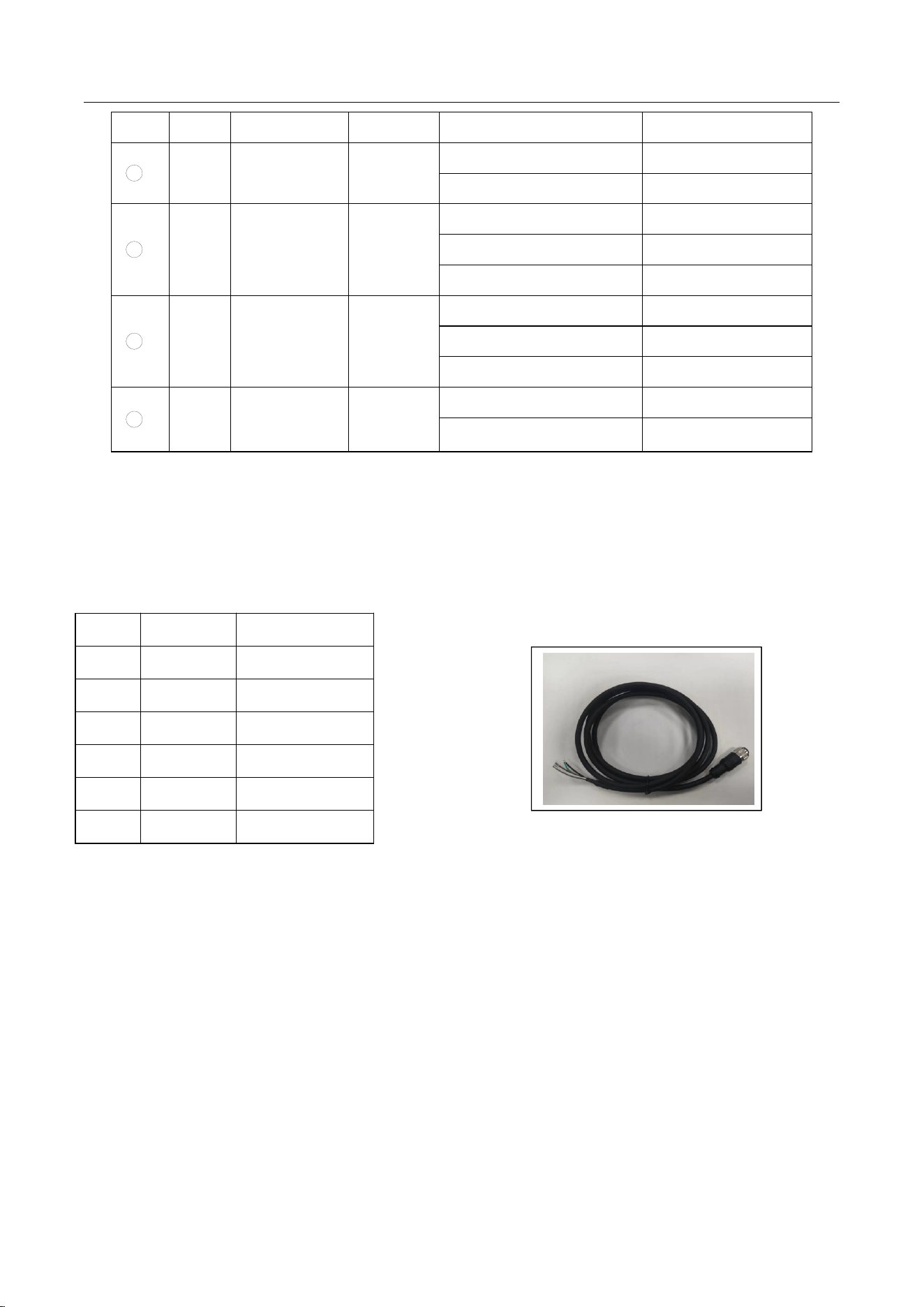
One end of RS485/RS232 uses M12-D code finished wire, and the other end should be
wired according to the definition in the table below. It is recommended to connect the
shielding ground and GND simultaneously.
No.
Colour
Description
1
Brown
RS485_A
2
White
RS485_B
3
Green
GND
4
Yellow
RS232_RX
5
Grey
RS232_TX
6
Black
Ground

APZC-SDR01
www.zifisense.com
- 7 -
4 Device Installation
4.1 Installation Note
4.1.1 Installation Environment
It is strictly forbidden to install device in harsh environments that are not conducive to AP
work, such as long-term high temperature, dusty, harmful gas, flammable, explosive,
susceptible to electromagnetic interference (large radar stations, transmitting radio
stations, substations), unstable voltage, high vibration or strong noise
The device installation environment should be kept properly dry, and device installation
in places prone to water accumulation, seepage, dripping and condensation is strictly
prohibited. It is also not recommended to install the device near the sea (less than 500m
from the sea), while avoiding the direction where the sea breeze is blowing
In the engineering design, the address that meets the environmental design
requirements of communication device engineering should be selected according to the
technical requirements of communication network planning and communication device,
taking into account climate, hydrology, geology, electricity, traffic and other factors
4.1.2 Relocation Safety
Avoid moving the device frequently after it has been installed
Turn off all power and disconnect power cords and other cables before moving or
handling
4.1.3 Electrical Safety
When carrying out electrical operations, the regulations and codes of the location must
be observed and the staff concerned must have the appropriate qualifications for the
operation
Check carefully for potential hazards in the work area, such as whether the floor is wet
Before installation, know the location of the emergency power switch in the room where
it is located and cut off the power switch when an accident occurs
Do not put the device in a wet place or allow liquids to enter the device
AP working place should preferably not be shared with the grounding device of electric
device and lightning protection grounding device, and be as far away as possible
Keep away from strong power wireless device such as wireless transmitter, radar
transmitter, high frequency and high current, microwave oven
APZC-SDR01
www.zifisense.com
- 8 -
4.2 Pre-installation preparation
4.2.1 Inventory of device and accessories
Before installing the device, please check whether the accessories are complete
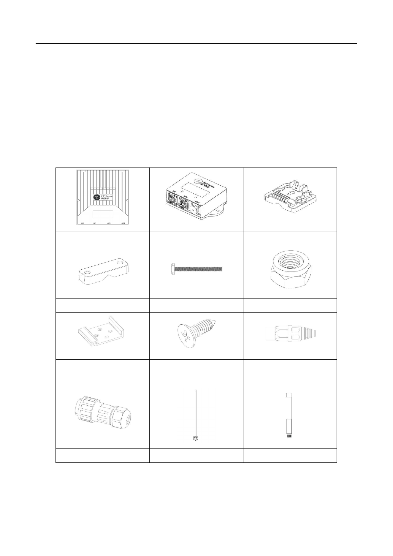
according to the delivery list, the following is the standard accessories list(Note: The following
list is for general delivery, the actual delivery (whether or not the contents of accessories are
included) may vary slightly and should be subject to the order contract. Please check your goods
carefully according to the packing list or order contract. If you have any questions or errors,
please contact the seller)。
1*Gateway
1*Power Module
1* Mounting bracket 1
1* Mounting bracket 2
2* T-bolts
2* Nuts
1* Guide rail clips
4* Self-tapping screws
2* Network port
connector
1* Power Connector
(1-2)* RF Antenna
1*4G Antenna
APZC-SDR01
www.zifisense.com
- 9 -
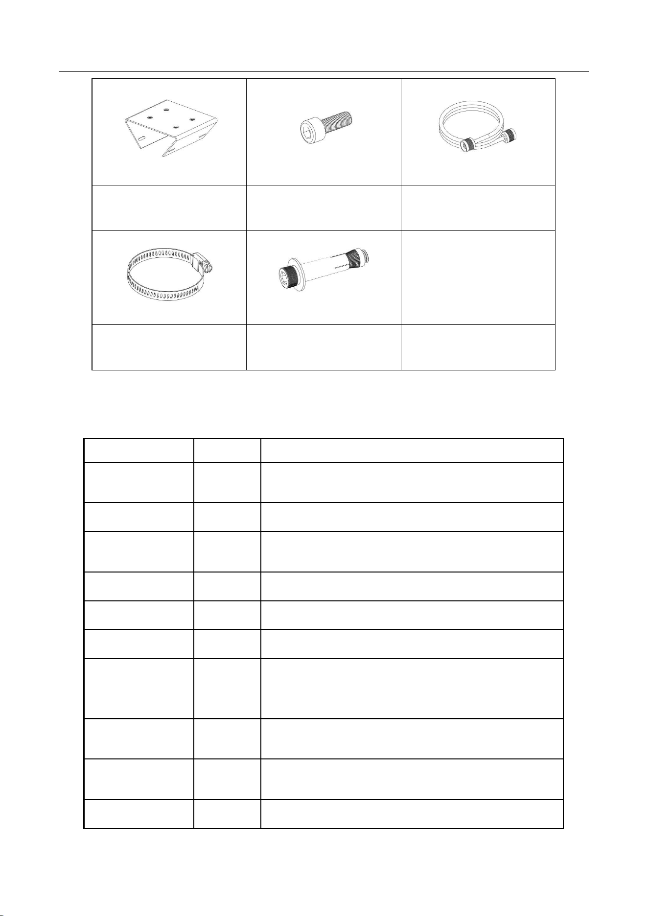
2*Antenna mounting
backplane
8* Hexagon socket
screws
2*Feeder Lines
4* Stainless steel cable
ties
2* Expansion screw
(optional)
4.2.2 Provide your own installation tools
Before the installation of the device, the customer is required to provide the following
installation tools and auxiliary materials:
Tools
Amount
Description
Crossed
screwdriver
1
mounting gateway brackets, antennas, hoops, etc.
Single screwdriver
1
mounting gateway brackets, antennas, hoops, etc.
No.10 open-end
wrench
1
fixing screws and nuts
Waterproof tape
1
gateway interface waterproofing
Waterproof mastic
1
gateway interface waterproofing
Electrician's knife
1
Cute waterproof tape and mastic
Outdoor Super
Category 5
Network Cables
1
For device power (length to be determined by the actual
alignment required)
Crystal Head
1
Need to pass the network cable through the waterproof
plug, and then make the network cable connector
Network cable
crimper
1
For PoE network cable production
Waterproof casing
several
For protection of exposed network cables (power cables)
APZC-SDR01
www.zifisense.com
- 10 -
Expansion screws
several
wall mounting
Impact Drill
1
wall mounting
Tool Pliers
1
For screwing the earth wire
Strapping
several
For alignment fixing
4.3 Installation steps
Steps
Name
Description
1
Main body mounting
Nail wall bracket/Holding bar
installation
2
ZETA Antenna
installation
ZETA Antenna mounting, interface
protection
3
4G/Network cable
installation
4G/Ethernet
4
Power supply
installation
Power supply installation, interface
protection
5
Gateway Grounding
Gateway grounding to prevent
lightning strikes
6
Dust cap waterproof
Unused interface is waterproofed by
dust caps
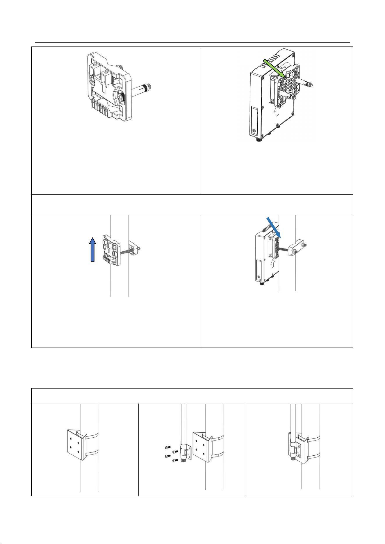
4.3.1 Step1:Main body mounting
Opt1:Nail wall bracket
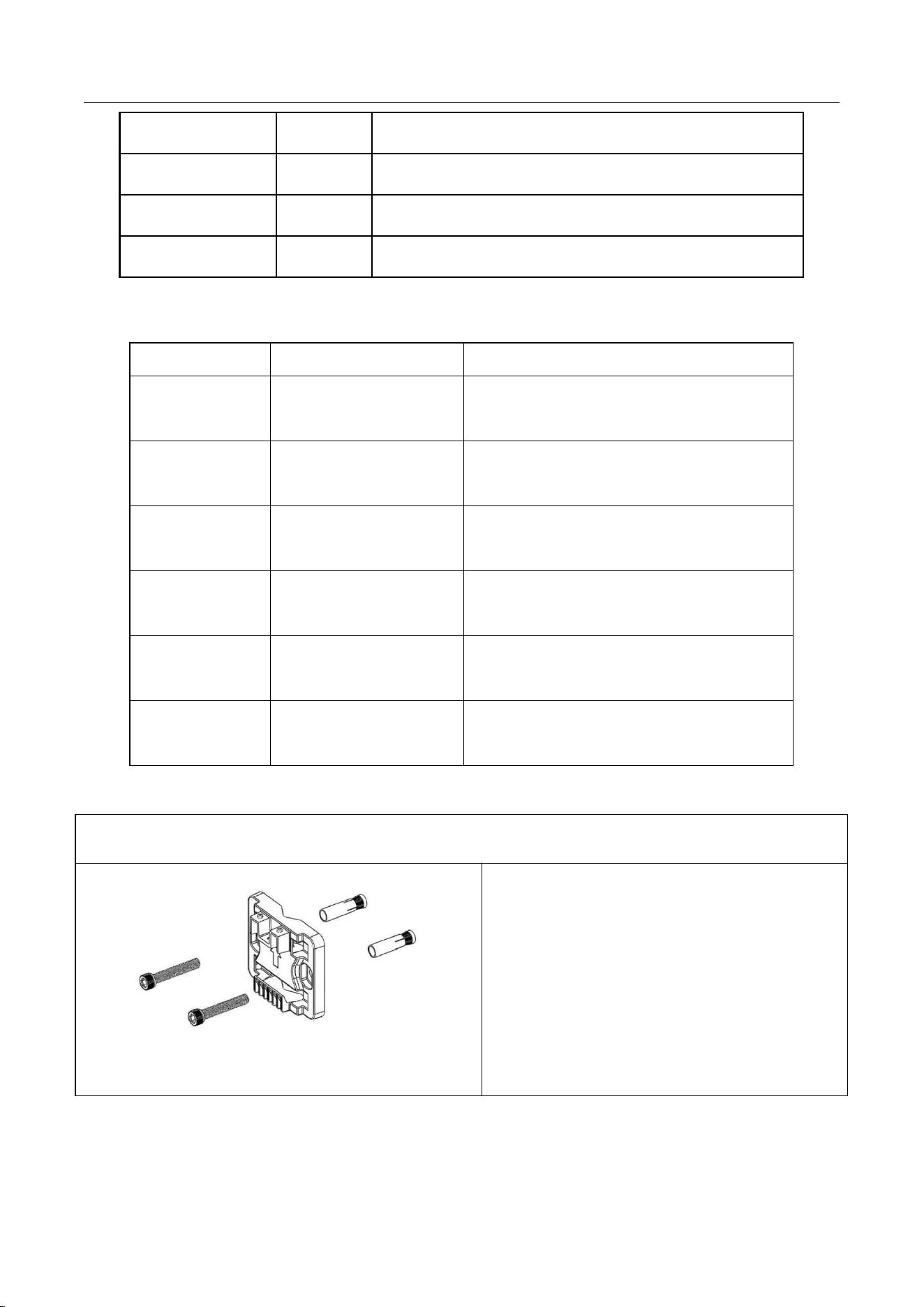
1 ) Pan the mounting bracket 1 to the target
position on the wall, and after marking the
position of the 4 screw holes on the wall with a
marker (the connection of adjacent holes should
be vertical), remove the mounting plate.
2)Drill four 60mm deep holes in the screw holes
marked on the wall with a 12mm drill bit.
①
APZC-SDR01
www.zifisense.com
- 11 -
1)Tap the 4 expansion bolts into the 4 drilled holes,
rotate and tighten the screws and then remove the
screws.
2 ) Attach the mounting bracket 2 to the wall with 4
screws.
Hang the gateway on the mounting bracket 1
and tighten the hexagonal screws.
Opt1:Holding bar
Lock the mounting bracket 1 and mounting bracket 2
to the holding bar with bolts and nuts (note that the
arrow of mounting bracket 1 is installed facing
upward).
Hang the gateway on the mounting bracket 1
and tighten the hexagonal screws.
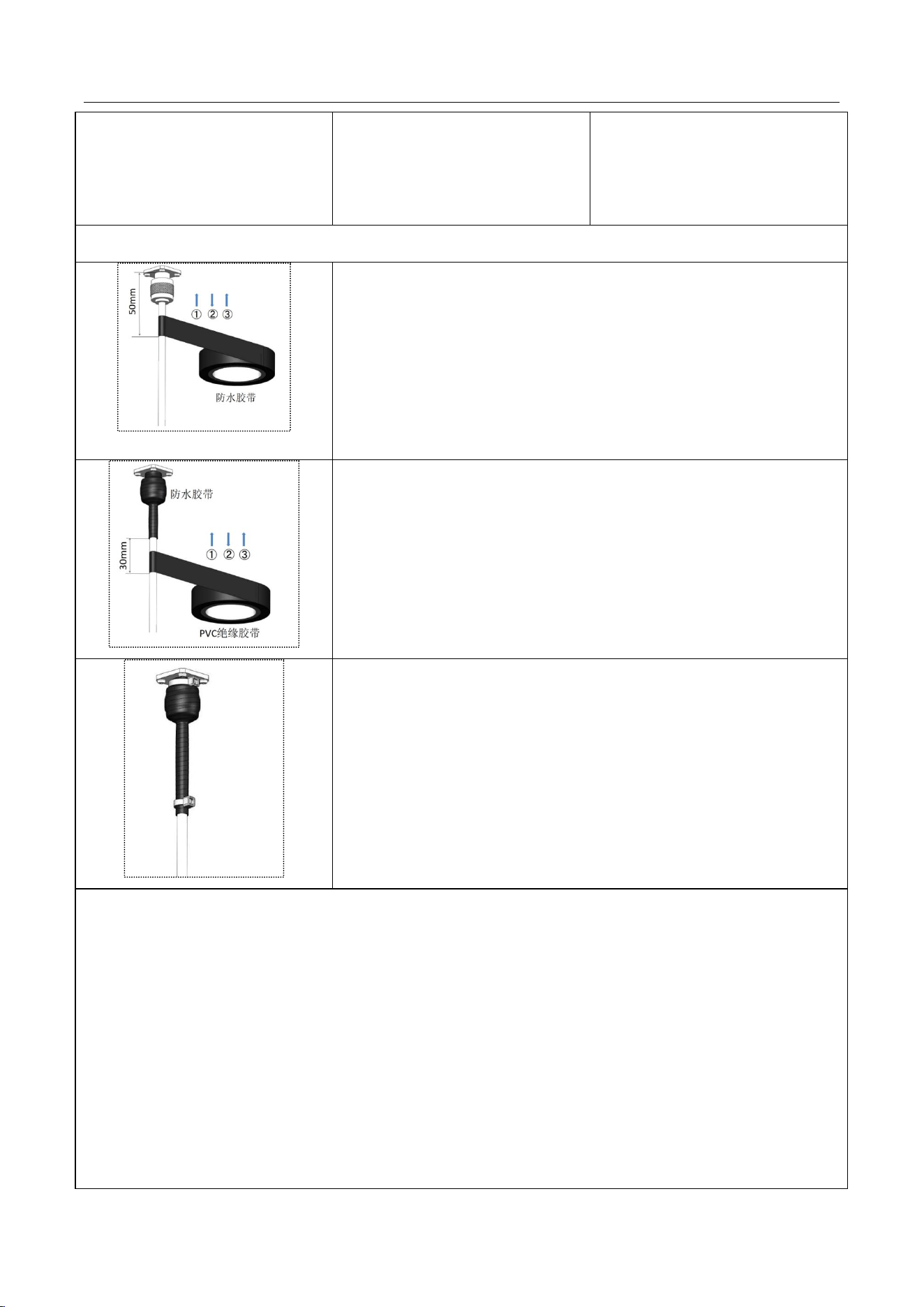
4.3.2 Step2: ZETA Antenna Installation
1)Antenna accessories installation
③
②
①
②
①
②
③
APZC-SDR01
www.zifisense.com
- 12 -
Tie the antenna backplane to the
holding bar with two stainless
steel.
RF antenna with four M6
hexagonal screws locked in the
backplane, note that the antenna
interval ≥ 1 m
Lock the screws to complete the
installation of antenna
accessories
2)Antenna interface waterproof treatment
Wrap three layers of waterproof tape
Start winding from the bottom 50mm of the antenna connector to
the top of the connector, first from bottom to top layer by layer, then
from top to bottom layer by layer, and finally from bottom to top layer
by layer. Cut the tape after all three layers are wrapped. When each
layer is finished, pinch the bottom tape by hand to ensure the
waterproof.
Wrap three layers of PVC insulation tape
Wrap from 30mm below the waterproof tape to the top of the
connector, first from the bottom to the top layer by layer, then from the
top to the bottom layer by layer, and finally from the bottom to the top
layer by layer. Cut the tape after all three layers are wrapped. When
each layer is finished, pinch the tape at the bottom by hand to ensure
that it is waterproof.
Tie the wire buckle at 3mm~5mm from the end of the PVC
insulation tape to prevent the tape from aging.
Notice:
When winding waterproof tape, the tape needs to be stretched evenly so that its length
is twice the original length.
When winding PVC insulation tape, the tape should not be stretched.
When winding the tape layer by layer, the upper layer covers more than 1/2 of the next
layer, and each layer should be pulled tight and compacted to avoid wrinkles and gaps.
Completely bond and self-fuse to avoid loosening.
Make sure that the adhesive side of the tape is covered with the tape already wrapped.
A margin of 3mm to 5mm is required when cutting the cable tie fastener.
APZC-SDR01
www.zifisense.com
- 13 -
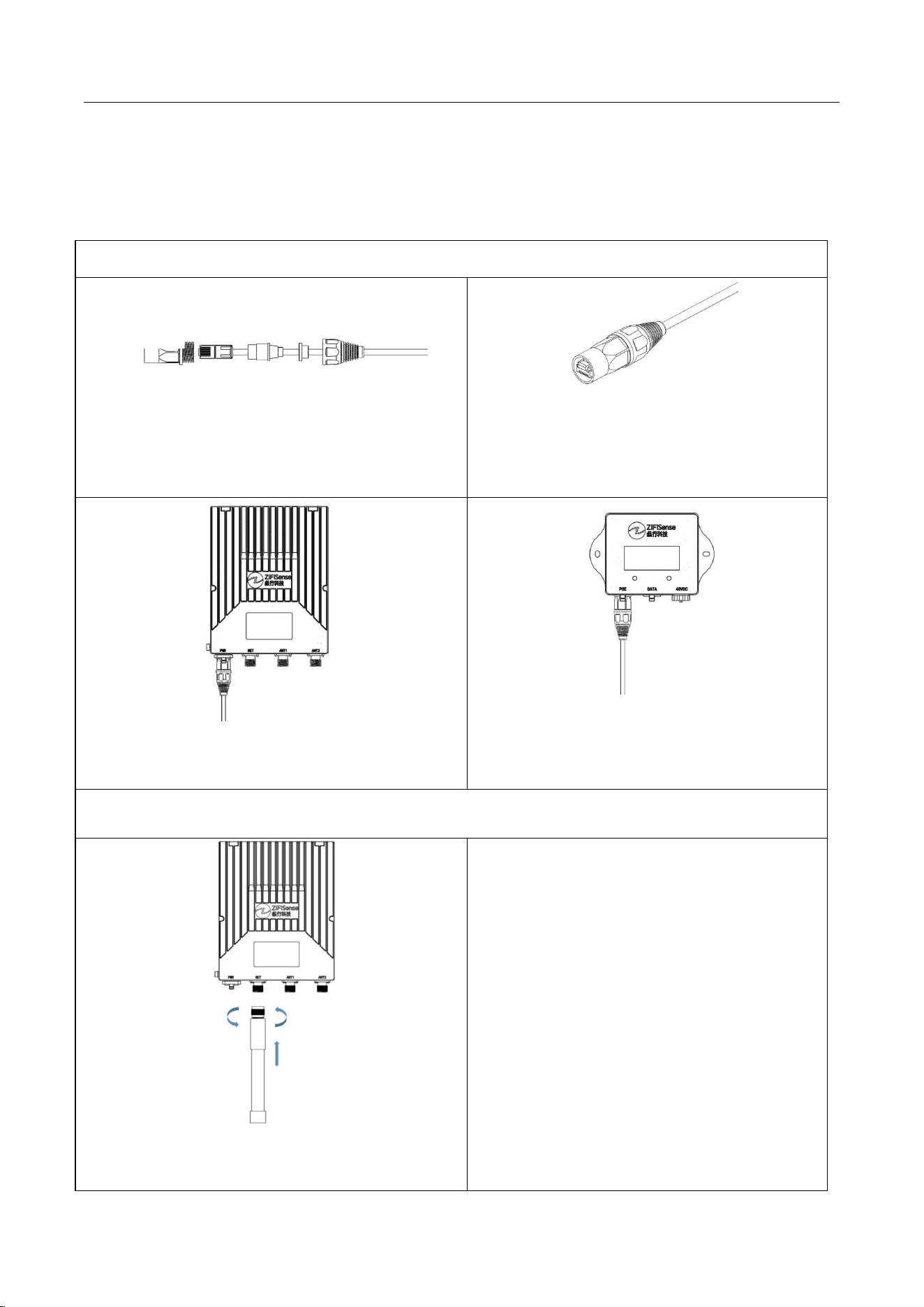
4.3.3 Step3: 4G antenna / network cable installation
Install 4G antenna when the system solution uses 4G backhaul, and install network
cable when the system solution uses Ethernet local deployment backhaul.
1)Network cable installation
Pass the unpressed end of the crystal head through
the waterproof plug and tail of the connector
Snap the crystal head into the connector head
and rotate the connector head and tail to
tighten.
Plug the connector into the gateway PWB terminal.
After the other end of the network cable is fitted
with a connector, plug it into the POE terminal
of the power module.
2)4G Antenna Installation
Screw the 4G antenna vertically down and
counterclockwise
①
②
③
④
APZC-SDR01
www.zifisense.com
- 14 -
4.3.4 Step4: Power supply installation
Power supply installation is divided into the main body of the power supply installation
and power cord installation, power cord interface protection three parts, including the
main body of the power supply installation to provide rail and nail wall installation
methods.
The power supply part provides +48V DC adapter or 220V AC adapter model, equipped
with DC power cord or AC power cord two installation instructions, including power cord
cable specification requirements: cable diameter 6 ~ 11.5mm, single line square line 0.5
~ 4mm².
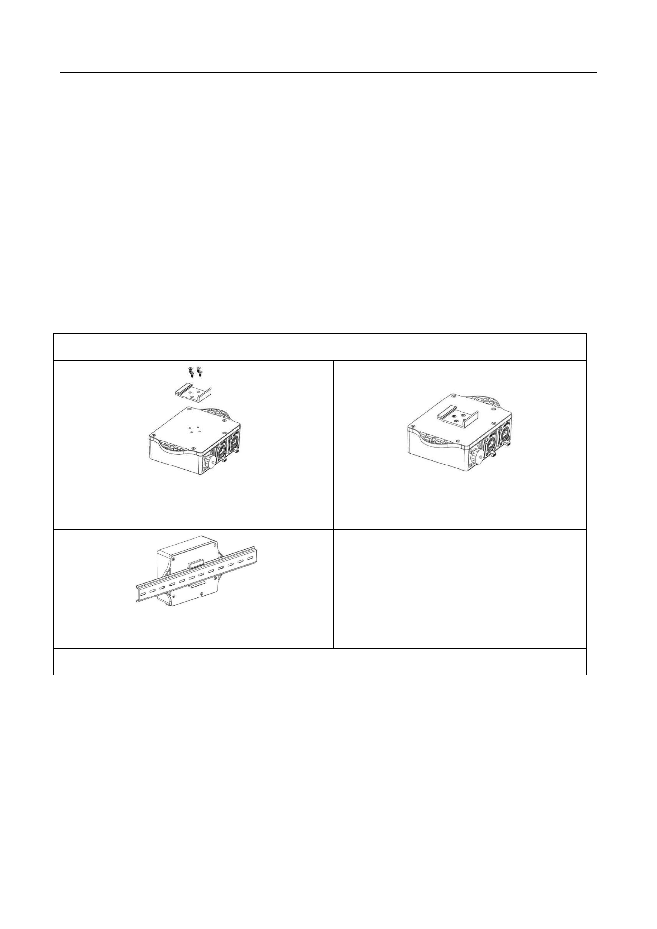
1)The steps and methods of power supply body installation are as follows.
Opt1: Guide rail installation
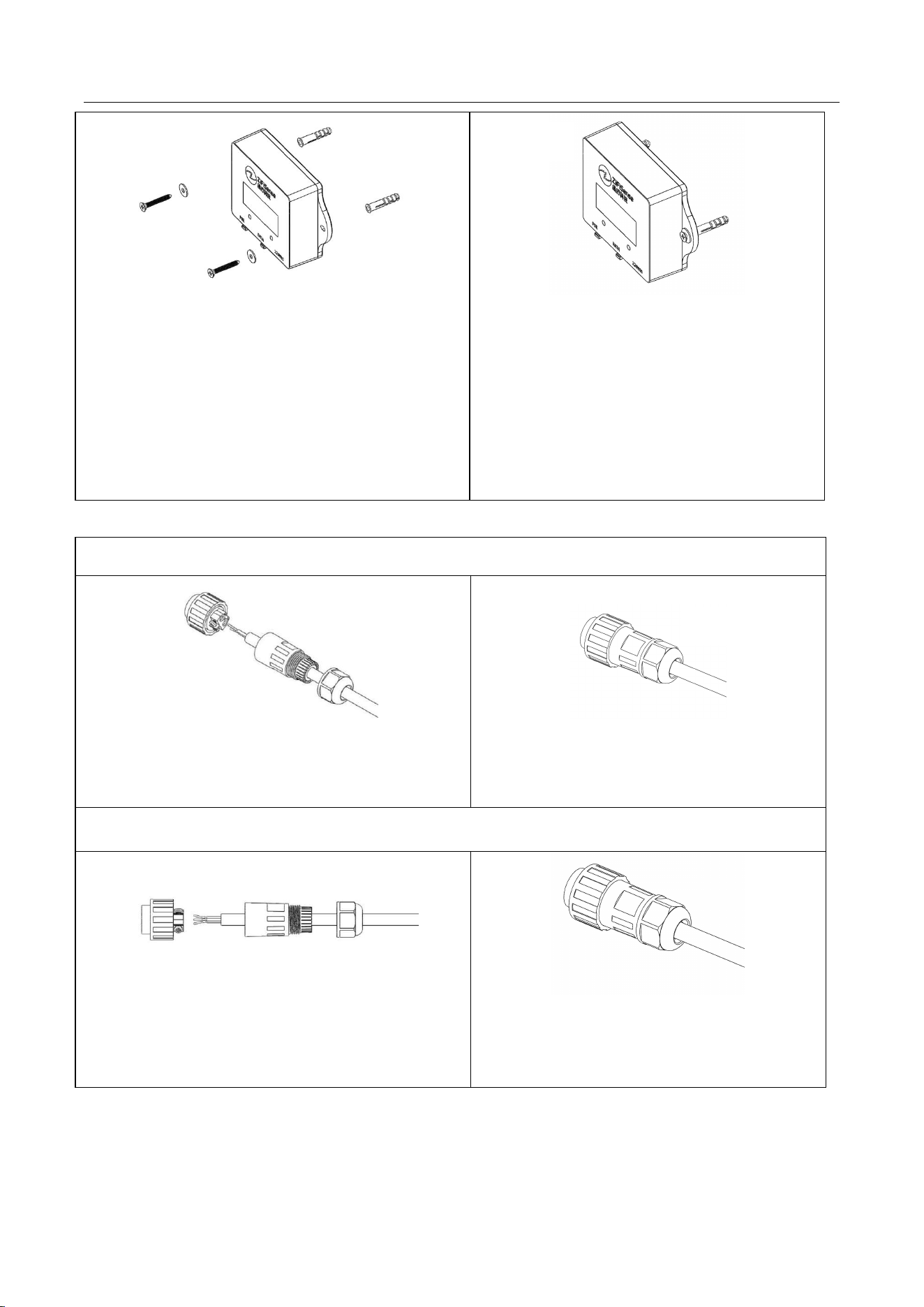
Lock the rail clips to the power module back cover
with 4 self-tapping screws.
Locking screw fixing.
Secure the power module to the U-rail.
Opt2: Nail wall installation
①
②
③
APZC-SDR01
www.zifisense.com
- 15 -
1) pan the power module to the target location on the
wall and mark the location of the 2 screw holes on
the wall with a marker;
2) Drill 2 holes 40mm deep in the marked screw
holes on the wall with an 8mm drill bit;
3) hammering 2 expansion screws into the 2 drilled
holes;
Locking the power module to the wall with 2
screws + spacers
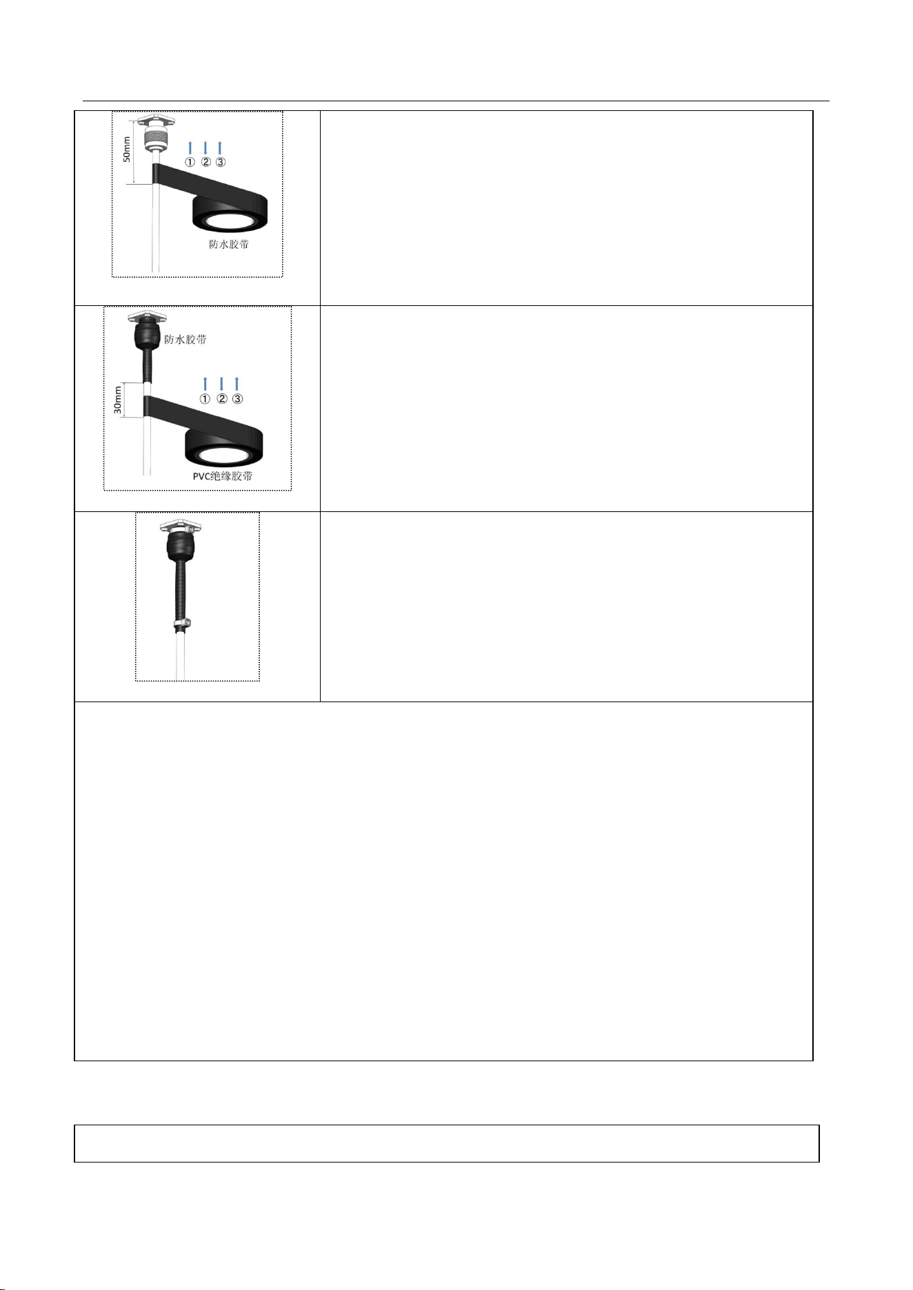
2)The power cord installation steps and methods are as follows.
DC Power Installation
Pass the power cable through the waterproof head
after stripping the core, positive->L, negative->N.
Rotate and tighten the three parts of the
connector
AC Power Installation
Strip the power cord after the core through the
waterproof head, fire -> L, zero -> N, ground ->
ground.
Rotate and tighten the three parts of the
connector
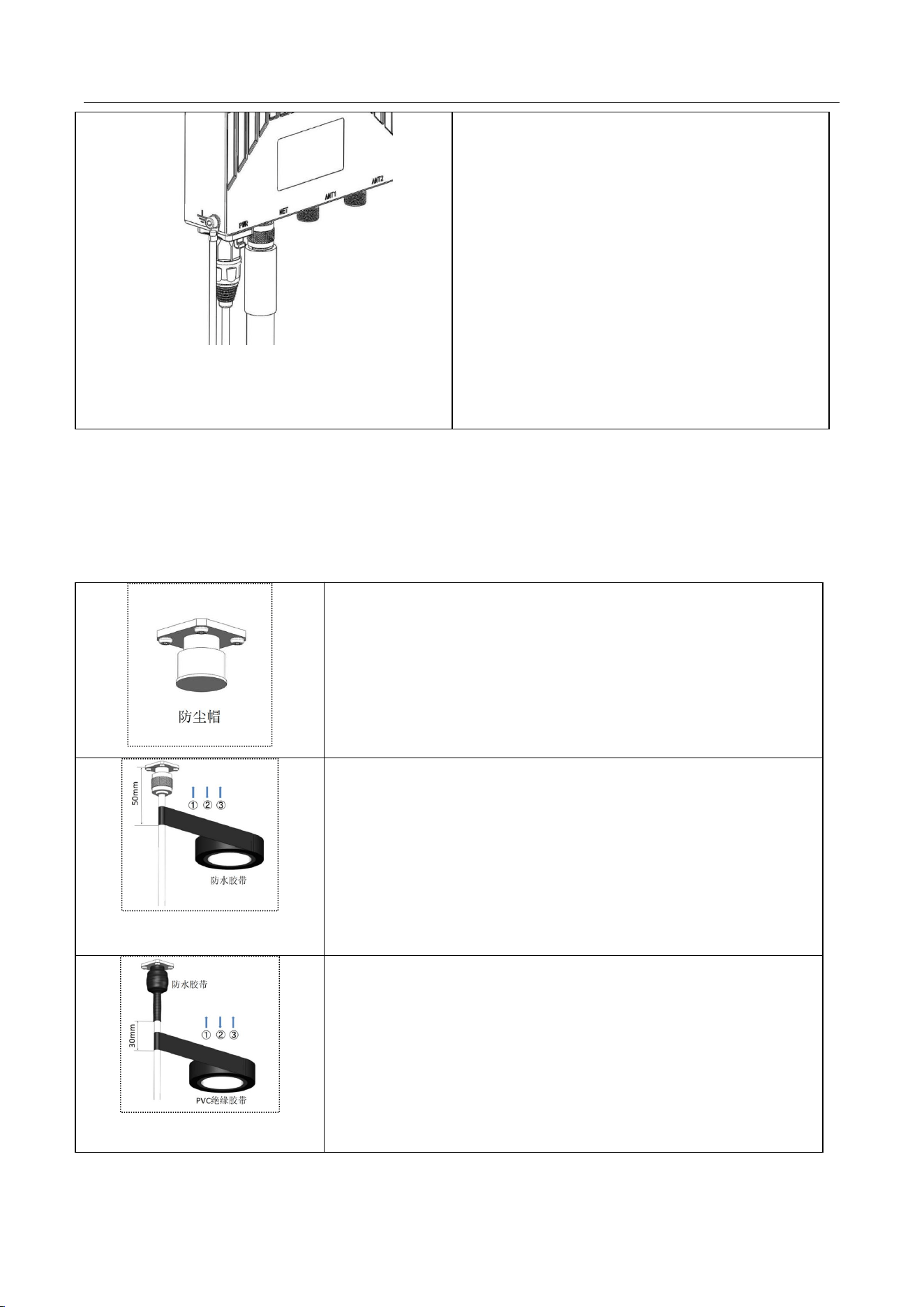
3)The steps for waterproofing the power data terminals are as follows.
①
②
①
②
①
②
APZC-SDR01
www.zifisense.com
- 16 -
Wrap three layers of waterproof tape
Start winding from the bottom 50mm of the antenna connector
to the top of the connector, first from bottom to top layer by layer,
then from top to bottom layer by layer, and finally from bottom to
top layer by layer. Cut the tape after all three layers are wrapped.
When each layer is finished, pinch the bottom tape by hand to
ensure the waterproof.
Wrap three layers of PVC insulation tape
Wrap from 30mm below the waterproof tape to the top of the
connector, first from the bottom to the top layer by layer, then from
the top to the bottom layer by layer, and finally from the bottom to
the top layer by layer. Cut the tape after all three layers are
wrapped. When each layer is finished, pinch the tape at the bottom
by hand to ensure that it is waterproof.
Tie the wire buckle at 3mm~5mm from the end of the PVC
insulation tape to prevent the tape from aging.
Notice:
When winding waterproof tape, the tape needs to be stretched evenly so that its
length is twice the original length.
When winding PVC insulation tape, the tape should not be stretched.
When winding the tape layer by layer, the upper layer covers more than 1/2 of the
next layer, and each layer should be pulled tight and compacted to avoid wrinkles
and gaps.
Completely bond and self-fuse to avoid loosening.
Make sure that the adhesive side of the tape is covered with the tape already
wrapped.
A margin of 3mm to 5mm is required when cutting the cable tie fastener.
4.3.5 Step5: Gateway Grounding
Gateway grounding requirements and steps
APZC-SDR01
www.zifisense.com
- 17 -
Requirements:
Grounding cable cross-sectional area required
6mm², grounding terminal OT6-5
Steps:
1 ) Fix the grounding terminal at the joint of the
antenna and tighten it with tool pliers
2 ) The other end of the grounding wire is
connected to the end of the lightning protection
network in the field construction area, pay
attention to the whole process to ensure the
connection with the metal
4.3.6 Step6: Dust cap waterproof
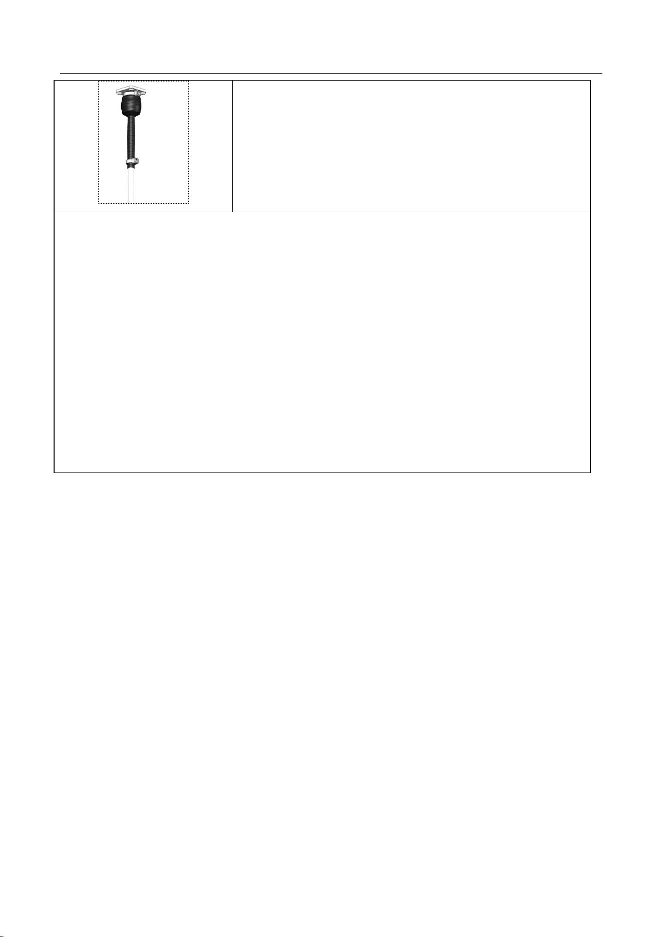
Do not remove the dust cap from the antenna connector that is not in use or is not in use for a while.
The operation steps are as follows.
Confirm that the dust cap has not been removed;
Wrap three layers of waterproof tape
Start winding from the bottom 50mm of the antenna connector
to the top of the connector, first from bottom to top layer by layer,
then from top to bottom layer by layer, and finally from bottom to
top layer by layer. Cut the tape after all three layers are wrapped.
When each layer is finished, pinch the bottom tape by hand to
ensure the waterproof.
Wrap three layers of PVC insulation tape
Wrap from 30mm below the waterproof tape to the top of the
connector, first from the bottom to the top layer by layer, then from
the top to the bottom layer by layer, and finally from the bottom to
the top layer by layer. Cut the tape after all three layers are
wrapped. When each layer is finished, pinch the tape at the bottom
by hand to ensure that it is waterproof.
APZC-SDR01
www.zifisense.com
- 18 -
Tie the wire buckle at 3mm~5mm from the end of the PVC
insulation tape to prevent the tape from aging.
Notice
:
When winding waterproof tape, the tape needs to be stretched evenly so that its
length is twice the original length.
When winding PVC insulation tape, the tape should not be stretched.
When winding the tape layer by layer, the upper layer covers more than 1/2 of the
next layer, and each layer should be pulled tight and compacted to avoid wrinkles
and gaps.
Completely bond and self-fuse to avoid loosening.
Make sure that the adhesive side of the tape is covered with the tape already
wrapped.
A margin of 3mm to 5mm is required when cutting the cable tie fastener.
5 FAQ
When the device is commissioned, if the gateway is powered up and no online prompt
is seen on the platform:
Check the power supply, make sure the gateway power supply is normal
Check the antenna, whether the antenna is connected correctly and whether it is
properly screwed
Check the network cable, check whether the network cable is normally connected
Check the SIM card, whether it is inserted normally
Check the status light, check whether the indicators are normal
Check the platform device status, in the (device management - gateway management)
list, check whether the current device status is "online"
Check whether the heartbeat packet (once every 3 minutes) data of the gateway is
normal
If it still does not work, you can re-power the gateway device and start it again to see if it
is restored

APZC-SDR01
www.zifisense.com
- 19 -

This device complies with part 15 of the FCC Rules. Operation is subject to the
following two conditions: (1) This device may not cause harmful interference, and (2)
this device must accept any interference received, including interference that may cause
undesired operation.
Any Changes or modifications not expressly approved by the party responsible for
compliance could void the user's authority to operate the equipment.
Note: This equipment has been tested and found to comply with the limits for a Class B
digital device, pursuant to part 15 of the FCC Rules. These limits are designed to
provide reasonable protection against harmful interference in a residential installation.
This equipment generates uses and can radiate radio frequency energy and, if not
installed and used in accordance with the instructions, may cause harmful interference
to radio communications. However, there is no guarantee that interference will not
occur in a particular installation. If this equipment does cause harmful interference to
radio or television reception, which can be determined by turning the equipment off and
on, the user is encouraged to try to correct the interference by one or more of the
following measures:
-Reorient or relocate the receiving antenna.
-Increase the separation between the equipment and receiver.
-Connect the equipment into an outlet on a circuit different from that to which the
receiver is connected.
-Consult the dealer or an experienced radio/TV technician for help.
This equipment complies with FCC radiation exposure limits set forth for an
uncontrolled environment. This equipment should be installed and operated with
minimum distance 20cm between the radiator & your body.