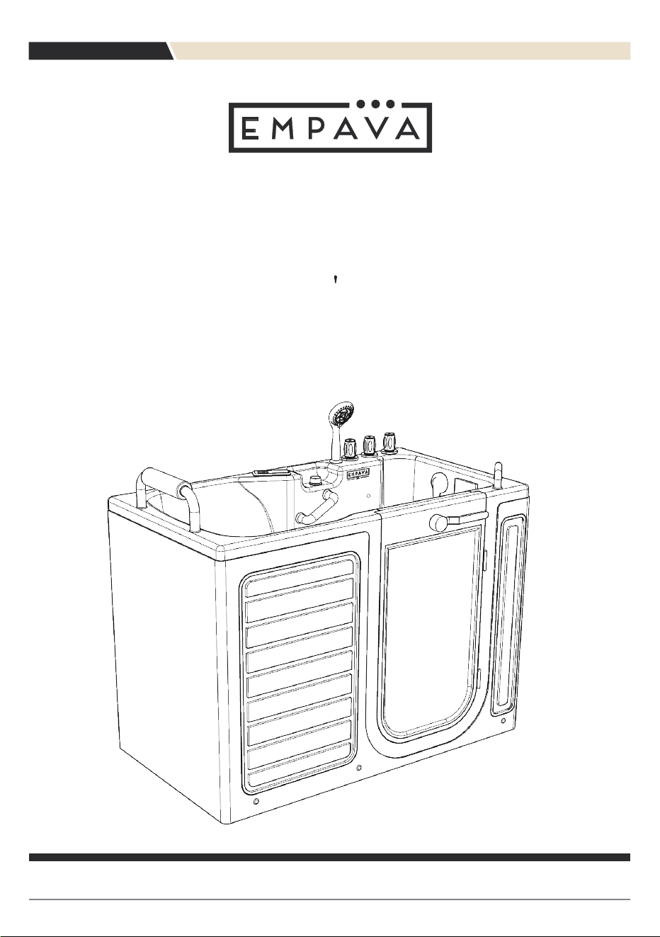
EMPV-54WIT08

TABLE OF CONTENTS
Instruction before installation
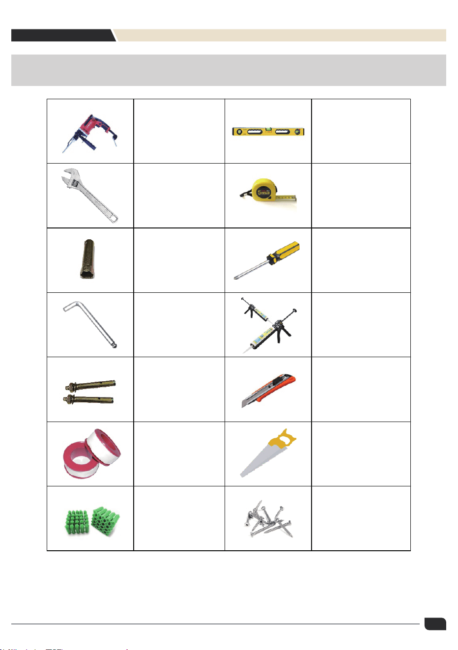
Preparing tools before installation
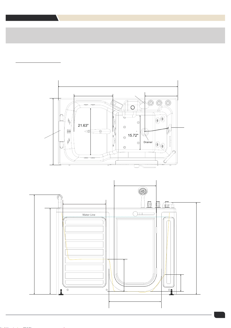
Size chart
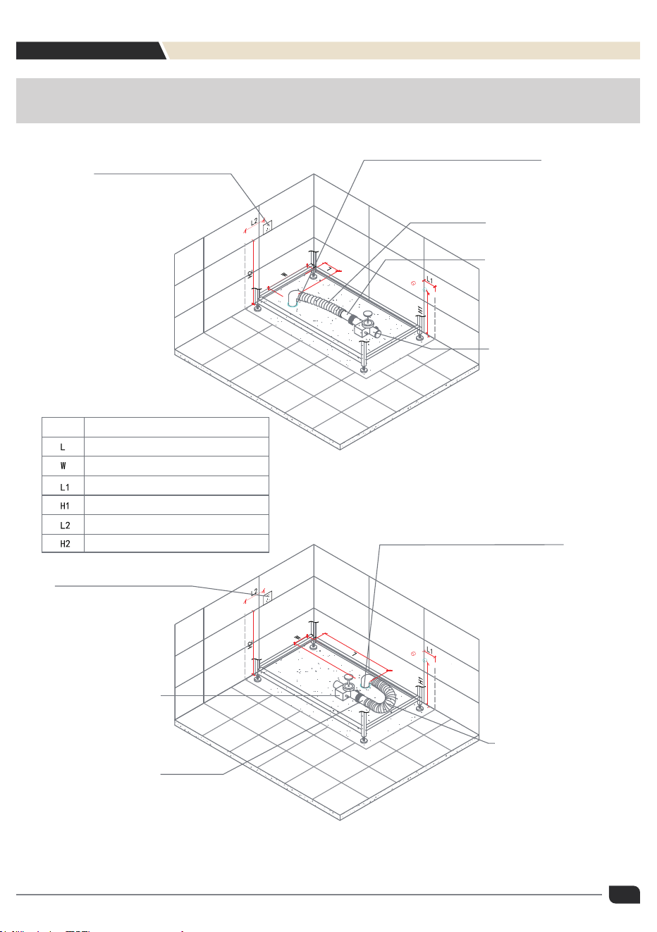
Bathtub Plumbing Locator Diagram
Installation procedures
Operational use
Care and Maintenance
Troubleshooting Guide
01
02
03
04
05
08
10
10

Instruction before installation
Testing your walk-in tub before installation by following procedures
WARNING :
when usingthis tub,the following basic procautions should be followed:
IMPORTANT :
Failure to follow the pre-installation instruction and water test the
bathtub before installation, manufacturer will not be liable for the
removal or installation of the bathtub.
1.Before unpack the unit,please inspect the carton carefully for any damage.any damage,
please take a picture or record all admage carefully.if necessary,contact your dealer/
distributor immediately. to file a freight claim.
2.Unpack the carton,then inspect thr carton carefully for any damage and check if all the
spare parts are there. if there is any damage,please take a picture or record all it carefully.
if necessary,contact your dealer/distributor immediately.
3.Water test before installation .although all our walk-in tub are water tested before they
leave our factory,there may be some loose of the hose connections due to the transport.
(1) Place the tub on a flat surface in an area where it may be drained after testing.
(2) Check if there is any loose of the connection system.
(3) Close the door,fill the tub with water to the overflow and allow standing for a few minutes
to inspect the tub for leaks.
Avoid the risk of electrical shock Connect only to a circuit protected by a grount-fault circuit-
innterrupter(GFCI).Grounding is required; All electrical connections should be made by a
licensed electrician,in accordance with requirements of national electrical codes and
procedures.
Installer/owenr bears all responsibilty to comply with all state and local building codes when
installing this unit
1
Preparing tools before installation
2
Impact drill
Adjustable
wrench
19mm Sleeve
5mm
hexagonal
key
10*100mm
expansion
bolts
Waste bunker
Expansion
tube
Spirit level
Tape rule
Phillips
screwdriver
Glass Glue
& Rob
Art knife
A hand saw
Stainless steel
screws
3
Size chart
54.33"x30.31"x39.76"
PRODUCT
size
Water Line
39.76"
19.27"
23.89"
14.91"
7.97"
41.93"
19.25"
45.48"
Switch Drainer
Shower Head
Drainer
Head Restraint
15.72"
21.63"
30.31"
54.33"
17.72"
15.02"
Bathtub Plumbing Locator Diagram
4
Five-hole socket (with a
separate circuit for grounding,
10A current)
Cold water
Right outer edge
line of the bathtub
Hot water
Cold water
Right outer edge
line of the bathtub
Hot water
Bathtub position
Bathtub position
Front outer edge
line of the bathtub
Front outer edge
line of the bathtub
Five-hole socket (with a
separate circuit for grounding,
10A current)
Reserved Bathtub Drain Outlet ø50-ø100
Flexible Drain Hose
Flexible Drain Hose
Rigid Drain Pipe
Rigid Drain Pipe
Drain Body Housing
Drain Body Housing
Bathtub Installation Plumbing
and Electrical Schematic 1
Bathtub Installation Plumbing
and Electrical Schematic 2
Legend in
the Diagram
Range of Values
Bathtub Adjustment Foot Position
Bathtub Adjustment Foot Position
Within the Range of 200-500mm from the Bathtub Surface
Space Below the Bathtub Surface
Within the Range of 200-500mm from the Bathtub Surface
Height from Ground: 600-800mm
Be sure to avoid the positions of the adjustable foot pads,
the drain body, and the hard drain pipe.
Reserved Bathtub Drain Outlet ø50-ø100
Be sure to avoid the positions of the adjustable foot pads,
the drain body, and the hard drain pipe.
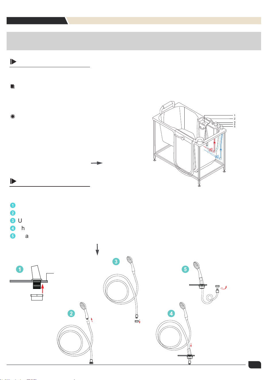
The bathtub's water supply pipes consist of cold water inlet and hot water inlet pipes. As
shown in the diagram, connect the cold water pipe and the hot water pipe to the corresponding
fittings reserved at the blade corners.
1、Hydraulic Flow Regulator
2、Handheld Showerhead (with Detachable Hose)
3、Hot Water Inlet Valve
4、Showerhead/Waterfall Control Valve
1
Start by installing the showerhead base.
2
Install the showerhead.
3
Unscrew the hexagonal nut at the other end of the shower hose.
4
Thread the shower hose through the showerhead base.
5
Reattach the hexagonal nut, then connect it to the shower control knob.
Installation procedures
5
Installation Step 1:
Connecting Bathtub Water Supply and Drainage Pipes (Faucet Assembly)
Installation Step 2:
Installation of the Showerhead
Manual
As shown in the diagram below
Hot water
Cold water
Bathtub surface
Connect the shower
control knob
As shown in the diagram right
Note:
If the bathtub is not leveled, the cylinder may be twisted and deformed, resulting in water leakage.
After adjusting the level of the bathtub, check whether the upper doorway is too narrow or too wide,
and if so, adjust it according to step 6
Installation Step 4:
Installation of the Backrest
Installation Step 5:
Leveling the Bathtub
6
Installation Step 3:
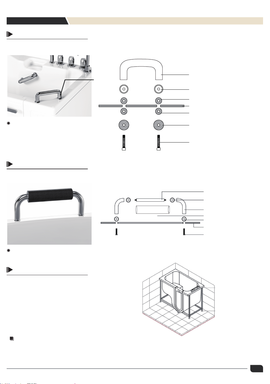
Installation of the U-shaped Handrail
U-shaped Handrail
Stainless Steel Decorative Cover
Rubber Washers
Rubber Washers
Metal Washers
Bolts
Bathtub Surface
Accessories List:
Stainless Steel Decorative Cover × (2)
Bolts × (2)
Rubber Washers × (2)
Metal Washers × (2)
Accessories List:
Decorative Cover × (2) Bolts × (2)
Bracket Central Axis
Decorative Cover
Bracket Legs
Bathtub Surface
Bolts
Backrest
Bracket Spindle
1、Use a wrench to loosen the nut on the upper
part of the footpad.
2、Twist the adjustable feet at the four corners of
the bathtub until the level of the cylinder surface.
3、Tighten the adjusted nut with a wrench.
Spirit level
Adjustable feet
U-shaped
Handrail
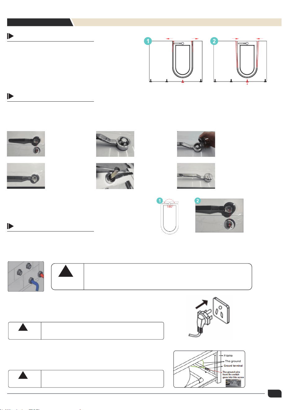
1、When the doorway is small up and big down,
adjust the adjusting foot under the door downward.
2、When the doorway is large and small,
adjust the adjustable feet under the door upward.
The door handle must be installed correctly in its position in order to avoid damage to the
internal mechanisms of the door.
2、Enlarge the diagram showing the installation
positioning point of the handle
For ease of use, our bathtub is equipped withstainless steel cold and hot water hoses (connector 3/4").
Please connect the cold and hot water hoses tothe bathroom's cold and hot water hoses accordingly
Make sure the ground is connected. One side of the ground
should be connected to the ground terminal of the motor and
the stainless steel frame; the other side should be connected
to the ground wires of the plug
1:
Align the positioning point
of the handle with the slot
of the door handle hole
and insert it
3:
The M12 threaded
rod is inside the
central threaded hole
5:
Tighten the exterior
decorative cover
6:
Installation completed
7
Installation Step 6:
Adjust the size of the door gap
Installation Step 7:
Door Handle Installation
Installation step 8:
2:
Press down with your
hand completely; it should
not be suspended.
4:
Use a socket wrench
to tighten
1、Diagram illustrating the range of handle rotation
180°
How to connect water ?
How to connect the clectricity ?
Notice
Notice
The red hose stands for hot water hose;the blue hose stands for cold water hose;
Drain-pipe should be installed with slope above 1:50;
Do not hold the drain-pipe and cold/hot water hoses when moving the bathtub,
and do not crash it with hard objects.
The bathtub must be connected to the ground. The power outlet
must be sealed well.Make sure the surface of each wire is in tact.
Notice
The product should be installedalongside ground
and electric leakageswitches by a licensed electrician.
Users need to prepare the power supply for 110-120V plugs,
install the proper dedicated plug with a ground electrode tothe
power line,Then insert the plug frmly.
From electrical source 110-120W
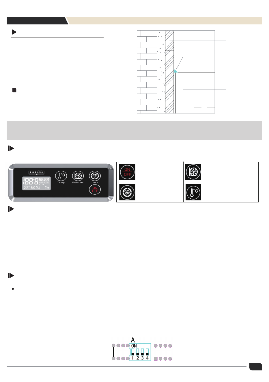
(1) Main Board Description and DIP Jumper Settings (see Figure 6)
1、Total On/Off Function Mode: Power On Mode and Standby Mod
2、Maximum 3KW Constant Temperature Heating Function, Water Temperature Display
and Setting Function
3、1 Water Pump
4、1 Wind Pump
5、The DIP switch can select different functions.
6、Error Code Indication
A1: OFF: Display Fahrenheit Temperature
ON: Display Celsius Temperature
A2: OFF: With Water Level Sensor
ON: Without Water Level Sensor
A3: OFF: Water Flow Sensor, Heater Does Not Operate When No Water Flow is Detected
ON: Without Water Flow Sensor
A4:
To ensure the stability and prolong the lifespan
of the bathtub, apply silicone sealant at the
points where the bathtub walls make contact.
This helps keep the bottom of the bathtub dry,
thus extending its lifespan
(as shown in the diagram below).
Overview of the Main System Panel
Function Brief
Operation of Common Functions
Installation completed
Note:
After installation is complete, please conduct an
electricity and water test to ensure that all systems
are functioning properly.
Wall tiles
Silicone sealant
Bathtub body
Figure 1: Panel Structure Diagram
Operational use
8
Total Open/Key Wind Pump On/Key
Water Pump On/Key Temperature Setting Key
Figure 6: Switchbank A/B

(2) When first powered on, the display shows “- - -”, indicating that the system is in
standby mode (see Figure 12)
(3) Operation for Powering On/Off
(4) Function Operations in Power On Mode
In standby mode (see Figure 12), press the " " key,The "---" disappears, and all loads are in the
off state.
Operation of the Surf Water Pump
The " " key controls the on/off state of the surf water pump. The surf water pump will automatically
turn off after 1 hour.
Note: The surf water pump will not start if the water level sensor detects no water.
Operation of the " " Key.
The " " key controls the on/off state of the wind pump. The wind pump will automatically turn off
after 15 minutes.
Temperature Control (77-104°F/25-40°C)
Press the " " key for the first time to enter the temperature setting mode. The set temperature
will flash on the screen. Before the temperature stops flashing, each press of the " " key
increases the set temperature by 1°C. Holding down the " " key continuously increases the
set temperature until it reaches the maximum setting of 40°C (104°F). Pressing the " " key
once more resets the set temperature to the minimum setting of 25°C (77°F).
Heating Function Description
When the temperature is in Celsius, the temperature control range is -1°C. This means that
when the set temperature TsetT_{set}Tset is 30°C, the heater will turn off when the water
temperature reaches 30°C. The heater will restart when the water temperature drops to 29°C
or below.
When the temperature is in Fahrenheit, the temperature control range is -2°F. This means that when
the set temperature TsetT_{set}Tset is 90°F, the heater will turn off when the water temperature
reaches 90°F. The heater will restart when the water temperature drops to 88°F or below.
In power on mode (see Figure 13), press the " " key, "---" appears, and all high-voltage loads
are turned off.
Attention:
1、All jumper settings are only effective when power is cycled. The power-off interval should be greater than
60 seconds.
2、All jumpers have been set at the factory. It is recommended that users do not change the product settings.
Note:
The heating function automatically starts when the water pump is turned on; the heating function automatically
stops when the water pump is turned off.
9
Figure 12: Standby Mode Figure 13: Power On Mode
EMPAVA APPLIANCES INC.
15253 DON JULIAN RD CITY OF INDUSTRY,CA 91745
TEL:888-682-8882
WWW.EMPAVA.COM
Walk-in bathtubs require regular maintenance to keep them clean and in top working condition.
After using the old man's tank, wash it with water and dry it with a clean rag.
Care and Maintenance
Troubleshooting Guide
SYMPTOMS PROBLEMS SOLUTIONS
Door leaks slightly
1.Door lock is not closed tightly;
2.There is some debris on the door seal.
1.Close the door lock tightly;
2.Clean the debris on door seal.
Water hose leaks
1.Rubber ring is not good;
2.Screw nut is not tightened, the connection
is not good.
1.Change a new rubber ring;
2.Tighten screw nut and make sure its
connection is good.
10
1.For equipment used in multi-family residences, a clearly labeled emergency switch must be
provided during installation. The user should have unobstructed access to this switch, and it must
be installed at least 1.52 meters away, near the equipment and within the user's line of sight.
2.If any wiring is damaged, it must be replaced immediately.
3.Power must be turned off before repairing or replacing any wiring connected to the equipment.
4.To prevent the risk of electric shock and/or water damage to the controller, all unused wire lead
outlets must be sealed with plugs.
5.This controller must not be installed near highly flammable substances.
6.Do not enter the water when any error indications are present!
Warnings and Error Indications