Due to our commitment to continued product improvement, specications are subject to change without notice. No. REF MANUAL
Krowne • 100 Haul Rd. Wayne, NJ 07470 • P: (800) 631-0442 • F: (973) 872-1129 • support@krowne.com • krowne.com
For Commercial Use Only. Not Residential.
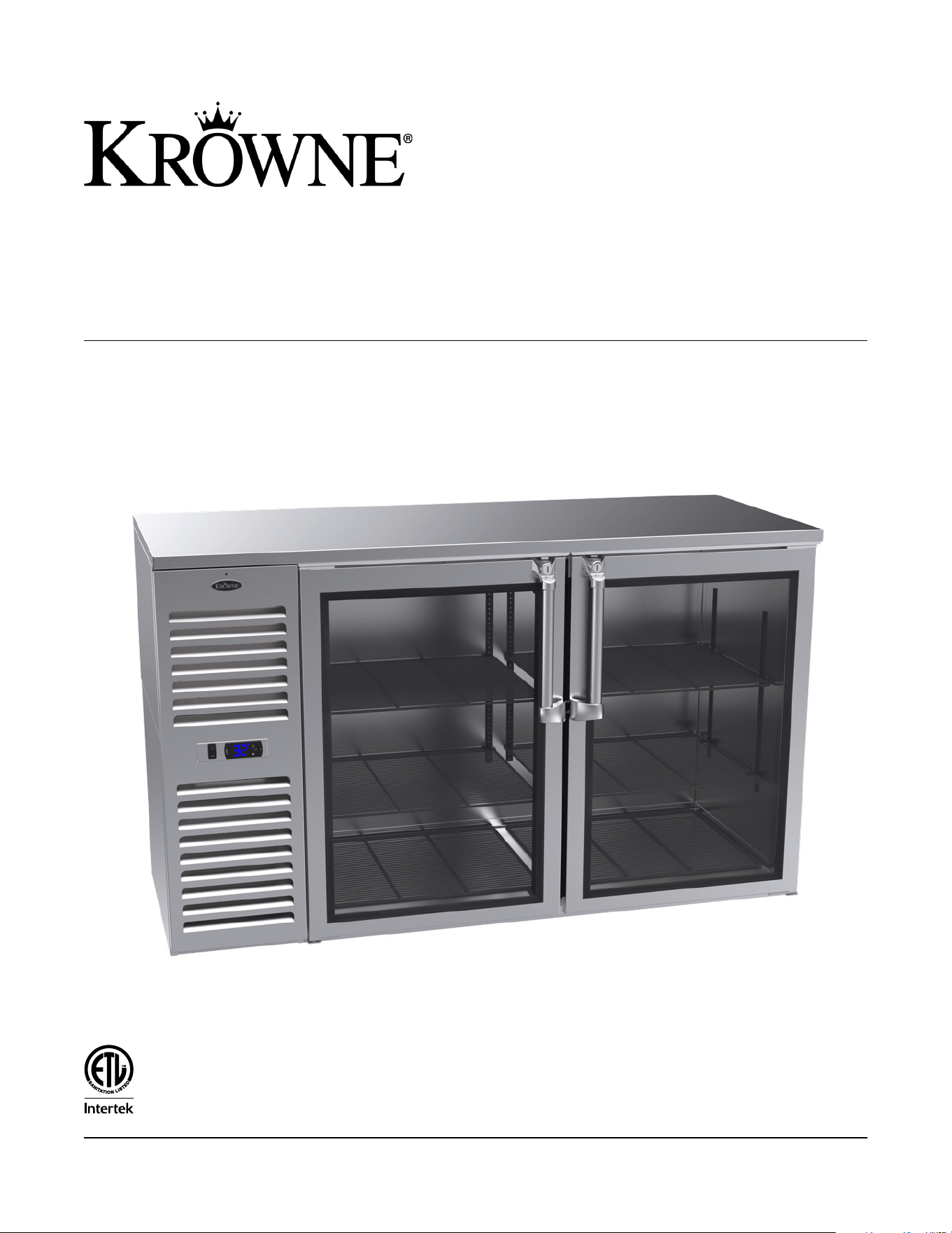
Refrigeration
Installation & Operating Manual
2 Krowne • 100 Haul Rd. Wayne, NJ 07470 • krowne.com
Refrigeration Installation & Operating Manual
Installation ............................................................................. 3
Operating Temperature and Defrosting .............................. 3
Thermostat.............................................................................. 4
Cleaning Instructions ............................................................ 4
Safety Notices ....................................................................... 4
Specifications .................................................................... 5-6
Wire Diagrams .................................................................. 7-8
Replacement Parts: Compressor Housing ........................... 9
Replacement Parts: Locks, Handles, & Doors ..............10-11
Replacement Parts: Mechanical & Lighting ...................... 12
Replacement Parts: Temperature Control .......................... 13
Replacement Parts: Shelving .............................................. 14
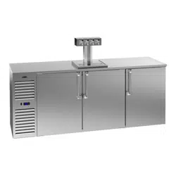
Direct Draw Coolers Parts & Accessories ......................... 15
Legs, Casters, Accessories..................................................16
Troubleshooting ................................................................... 17
Changing a Door Handle .................................................. 18
Changing a Stainless Steel Top ......................................... 19
Installing a New Stainless Steel Top ..................................20
Changing a Swing Door .................................................... 21
Changing a Sliding Door ................................................... 21
Changing LED Lights ........................................................... 22
Adjusting Shelving ..............................................................22
Installing Dispensing Faucets .............................................23
Installing Dispensing Towers ..............................................24
Warranty .............................................................................25
Terms ....................................................................................26
Notes ...................................................................................27
Table of Contents
Need replacement parts?
Refrigeration replacement parts available for all units.
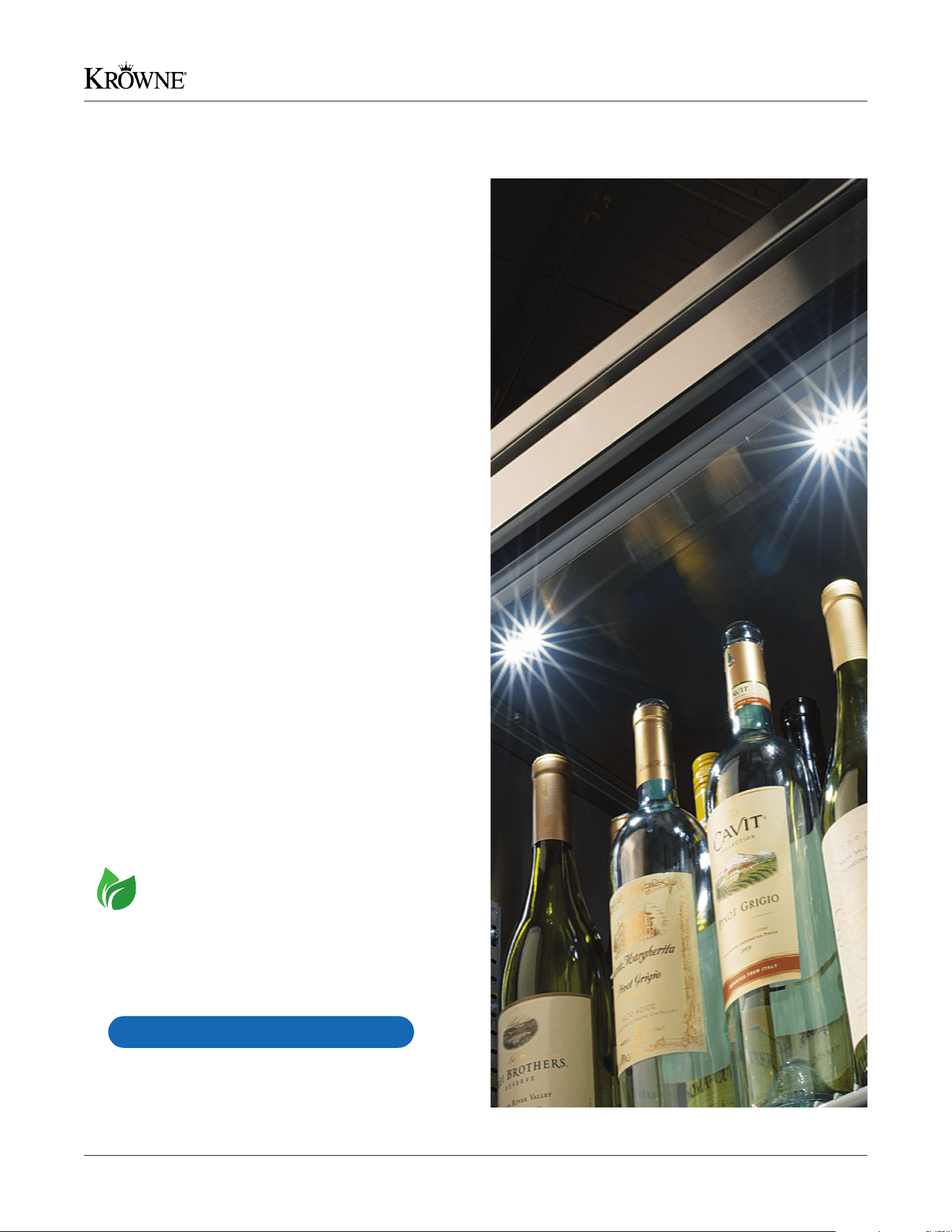
Natural
Refrigerant
Natural Refrigerant
Hydrocarbon refrigerants are natural, nontoxic refrigerants
that are one of the most climate-friendly and cost-efcient
refrigerants with no ozone depleting properties.
partsbykrowne.com
3Krowne • 100 Haul Rd. Wayne, NJ 07470 • krowne.com
Refrigeration Installation & Operating Manual
Installation
Operating Temperature & Defrosting
SELF-CONTAINED UNITS:
Digital thermostat can be found on the front condensing unit cover. To set to desired temperature, follow the steps below.
1. Press SET for 1 second. The set value will start flashing after a few moments
2. Increase or decrease the value using UP or DOWN
3. Press SET to confirm new value
Manual defrost cycle: Press DOWN for more than 3 seconds
The operating temperature for the Self-Contained Back Bar Cooler is preset at the factory for an average of 35°F.
Average operating range is from 29°F to 38°F.
Remote units need to be set by a certified refrigeration technician.
CAUTION:
This temperature is only a set point. If set to 32°F, product will not be 32°F and air temperature inside unit will not be 32°F.
Operating temperature/average temperature is usually 4°F to 5°F above set temperature.
Inspection Upon Receipt
Remove all shipping material from unit before operation.
Please inspect the unit for any hidden freight damage and
report any damage immediately to Krowne Metal Corp.
If included, install optional casters or legs to bottom of
unit. Please avoid turning unit on its side or rear to install
accessories. If this cannot be avoided, unit must be left in
the upright position for 24 hours before operating. All units
come equipped with predetermined mounting holes and self
starting bolts for easy install (bolts are provided only when
casters or legs are ordered from factory). It is important
to check that casters or legs are securely attached with
appropriate mounting hardware.
Electrical Requirements
115 Volt AC, 1 Phase, 60Hz. We recommend using a
dedicated 15 amp circuit minimum. 8’-0” grounded
cord standard on Self Contained Back Bar Coolers, Bottle
Coolers and Mug Frosters. Remote units come with a
terminal block inside the box for a hard wire connection
(supplied by the end user).
Plumbing
Self-Contained Back Bar Coolers have an evaporating pan
and do not require any plumbing hook-up. Remote units
require a drain hook-up. We recommend using 1/2” tubing
and running it through the same knockout used for the
refrigeration hook-up.
At Krowne Metal Corporation we are dedicated to customer satisfaction. This installation guide is provided to clarify and
answer any questions you may have regarding our line of Commercial Refrigerators. Please read this guide before attempting
installation or operation. Thank you for choosing Krowne as your refrigeration provider.
Installing of Shelves (Back Bar Coolers)
Shelves and installation clips are shipped within the cooler.
Shelves can be installed based on owner’s preference.
Location
Place unit in desired location and level. It is important for
the unit to be level, or it will not drain properly, and the
doors will not close properly, which in turn will affect the
function of the cooler and void any factory warranty. Allow
2” clearance for Back Bar Coolers in the back. If unit is being
installed directly to the oor, without legs or casters, the
equipment is required to be sealed to the oor or counter
to establish proper sanitary operation.It is recommended to
be sealed to the oor using an NSF certied silicone sealer.
The intended purpose of sealing equipment to the oor is to
prevent liquid spillage passing under inaccessible portions
of the equipment and to maintain the equipment’s NSF
sanitation certication. DO NOT BLOCK OR OBSTRUCT
FRONT GRILL. THIS EQUIPMENT IS INTENDED FOR
USE IN AN AREA WHERE THE AMBIENT TEMPERATURE
TYPICALLY DOES NOT EXCEED 75°F (24°C).
4 Krowne • 100 Haul Rd. Wayne, NJ 07470 • krowne.com
Refrigeration Installation & Operating Manual
Make sure to avoid all products which may corrode the
stainless steel such as steel wool and chlorine based
bleaches. The cooler should be cleaned with a mild
detergent, warm water and a soft cloth. All cleaning
materials should be washed away and the cooler
completely dried.
DO NOT CLEAN WITH ANY BLEACH PRODUCTS
Condenser must be cleaned every 60 days or may void
warranty. Prior to removing front panel on Back Bar Coolers,
you must shut off the unit (shut off switch is located next
to digital thermostat). Remove front grill for access to
condenser. If the condenser is not regularly cleaned, loss of
efciency and ultimately condenser failure may occur.
Doors as well as the interior of the cooler should be cleaned
occasionally to prevent buildup of liquids and other matter
that may interfere with operation. To clean these surfaces use
a mild detergent, warm water and a soft cloth. Dry completely!
DANGER: Risk of re or explosion. Flammable refrigerant
used. To be repaired only by trained service personnel.
Consult repair manual/owner’s guide before attempting
to service this product. Dispose of properly in accordance
with federal or local regulations. All safety precautions must
be followed. Do not puncture refrigerant tubing.
IMPORTANT: Keep clear of obstruction all ventilation
openings in the appliance enclosure or in the structure for
building-in.
IMPORTANT: Component parts shall be replaced with like
components. Servicing shall be done by factory authorized
service personnel, as to minimize the risk of possible ignition
due to incorrect parts or improper service.
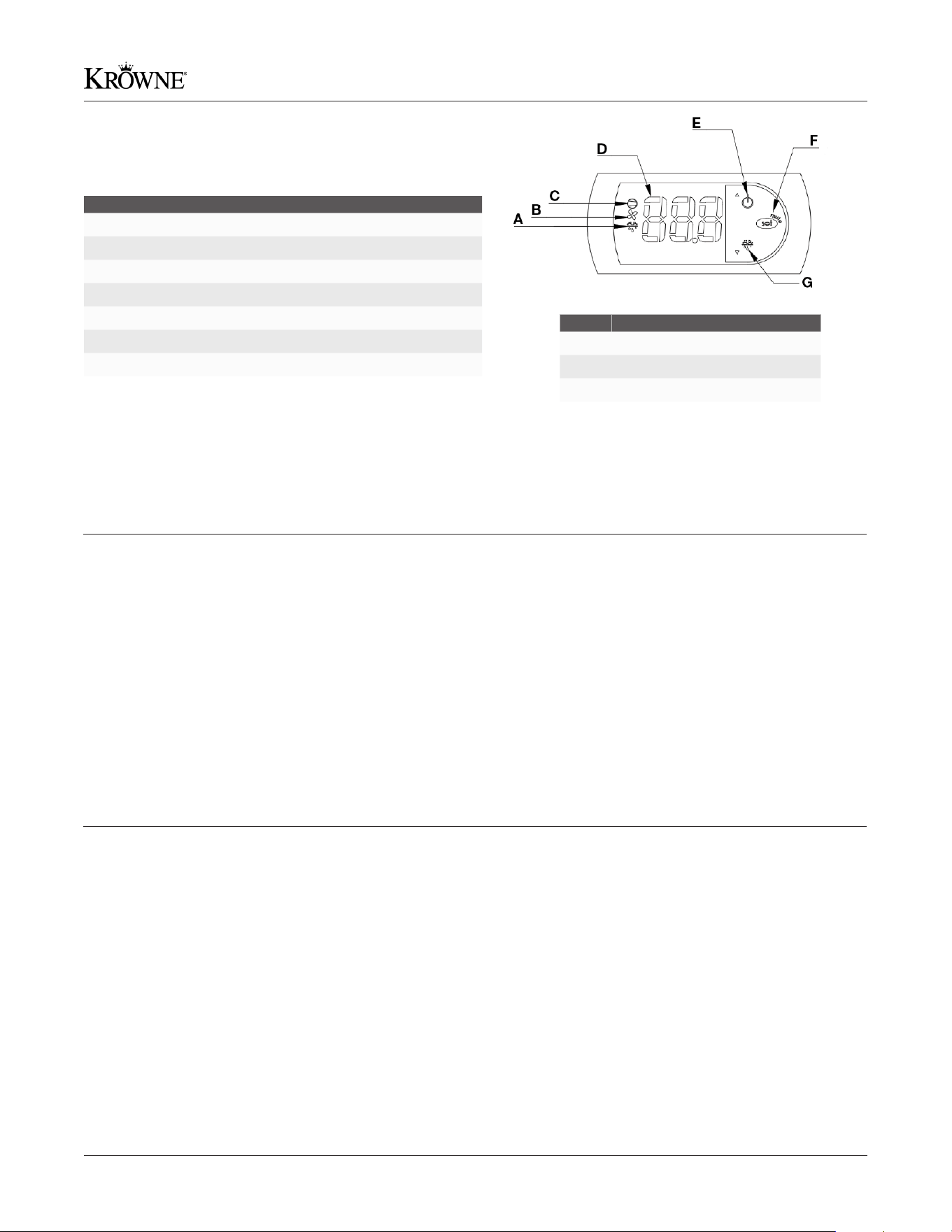
Thermostat Key
Alarm Key
Code Alarm
E0 Box temperature probe error
E1 Evaporator defrost probe
DF Unit is running in defrost
Label Alarm
A Defrost ON/OFF LED
B* Fan ON/OFF LED
C Compressor ON/OFF LED
D Temperature Display (Avg. Inside Air Temp.)
E UP Button or HOLD for ON/OFF Compressor Power
F SET/MUTE Button
G DOWN Button or HOLD for Defrost Override
IMPORTANT: All service should be performed by a certied
refrigeration technician.
*B is only available on Mug Froster Congurations
Note:
All Mug Frosters have an evaporator coil defrost
every 4 hours and a full box defrost between
5 AM - 9 AM daily. Time is preset at factory.
Warning:
If the thermostat is flashing the word “OFF” and
the temperature, this means your compressor
turned off. To resolve, hold the power button for
3 seconds and the compressor will turn on.
Below Notices apply to Hydrocarbon Refrigeration only (R290)
Thermostat
Cleaning Instructions
Safety Notices
5Krowne • 100 Haul Rd. Wayne, NJ 07470 • krowne.com
Refrigeration Installation & Operating Manual
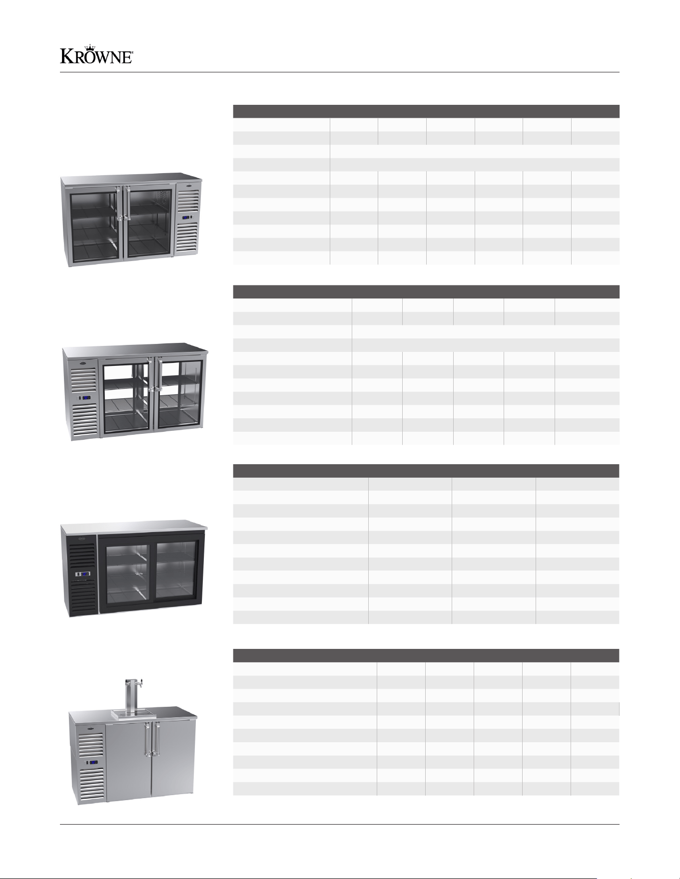
Model No. BS36 BS60 BS84 BS108 NS52 NS72
Number of Doors 1 2 3 4 2 3
Length 36”L 60”L 84”L 108”L 52”L 72”L
Depth All models are 24”D. 25”D with optional 1” stainless steel top
Height All models are 35”H. 36”H with optional 1” stainless steel top
Refrigerant Type R290 R290 R290 R290 R290 R290
Charge 2.75 oz. 2.6 oz. 3.1 oz. 3.85 oz. 2.6 oz. 2.6 oz.
Design Pressure H/L 450/130 450/130 450/130 450/130 450/130 450/130
H.P. 1/5 1/4 1/3 1/3 1/4 1/4
Full Load Amps 1.7 2.2 2.7 2.8 2.2 2.2
Case Capacity 7.0 15.7 24.5 30.0 12.0 19.0
Weight (lbs.) 285 360 480 525 300 420
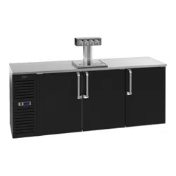
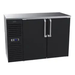
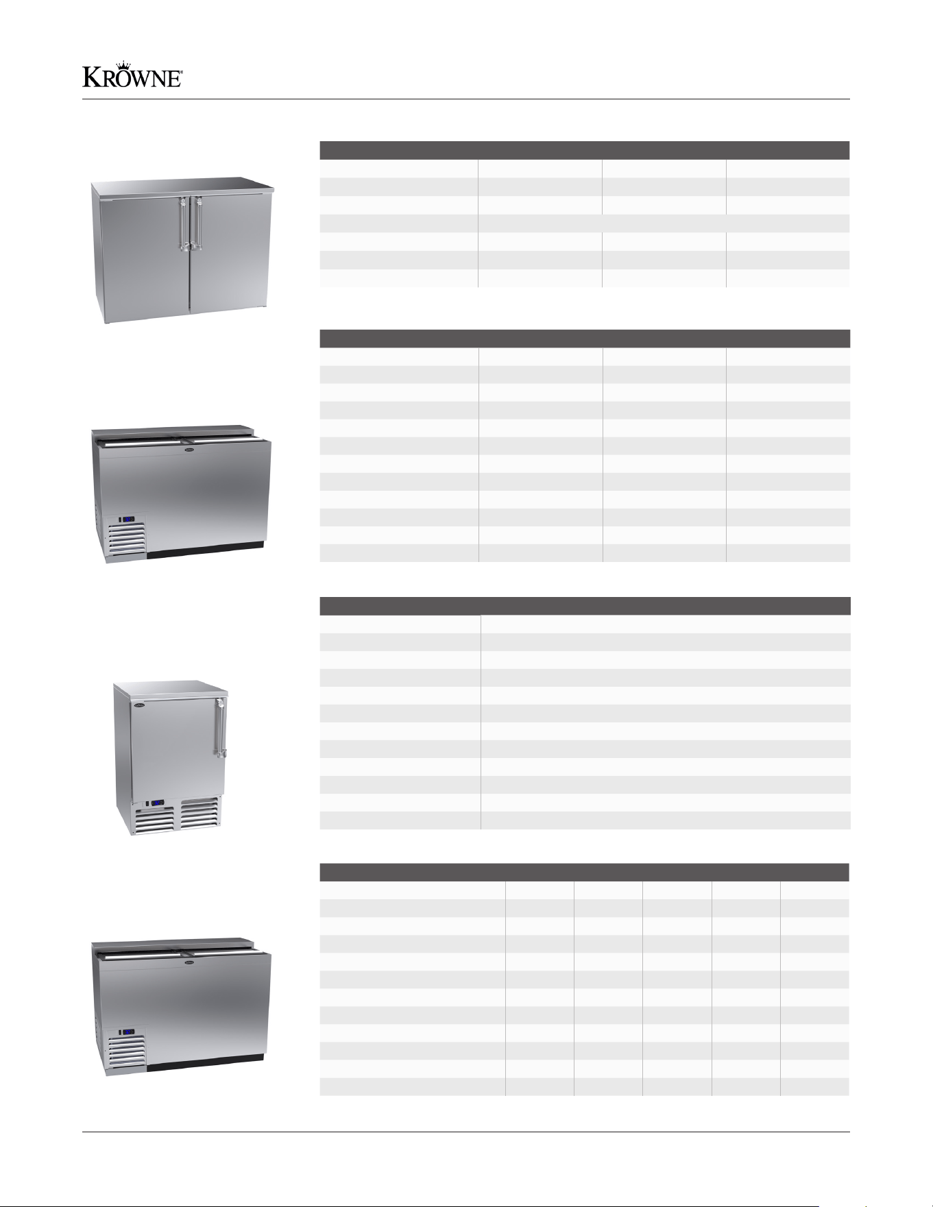
Self-Contained
Back Bar Coolers
All units are 115V, 1 Phase, 60 Hz
Pass Thru
Back Bar Coolers
All units are 115V, 1 Phase, 60 Hz
* With optional 1” stainless steel top, PTSD60L is 27-1/4”D and 36”H
Sliding Door
Back Bar Coolers
All units are 115V, 1 Phase, 60 Hz
Direct Draw Coolers
All units are 115V, 1 Phase, 60 Hz
Model No. SD60 SD108 PTSD60L
Number of Doors 2 4 4
Length 60”L 108”L 60”L
Depth 25”D 25”D 26”D *
Height 36”H 36”H 35”H *
Refrigerant Type R290 R290 R290
Charge 2.6 oz. 3.85 oz. 2.6 oz.
Design Pressure H/L 450/130 450/130 450/130
H.P. 1/4 1/3 1/4
Full Load Amps 2.2 2.8 2.2
Case Capacity (12 oz. Bottles) 15.7 31 15.7
Weight (lbs.) 360 720 380
Model No. KPT36L KPT52L KPT60L KPT72L KPT84L
Number of Doors 2 4 4 6 6
Length 36”L 52”L 60”L 72”L 84”L
Depth All models are 26”D. 27-¼”D with optional 1” stainless steel top
Height All models are 35”H. 36”H with optional 1” stainless steel top
Refrigerant Type R290 R290 R290 R290 R290
Charge 2.75 oz. 2.6 oz. 2.6 oz. 2.6 oz. 3.1 oz.
Design Pressure H/L 450/130 450/130 450/130 450/130 450/130
H.P. 1/5 1/4 1/4 1/4 1/3
Full Load Amps 1.7 2.2 2.2 2.2 2.7
Case Capacity (12 oz. Bottles) 7.0 12.0 15.7 19.0 24.5
Weight (lbs.) 290 320 360 460 520
Model No. DB36 DB52 DB60 DB72 DB84 DB108
Number of Doors 1 2 2 2 3 4
Length 36”L 52”L 60”L 72”L 84”L 108”L
Depth 25”D 25”D 25”D 25”D 25”D 25”D
Height 36”H 36”H 36”H 36”H 36”H 36”H
Refrigerant Type R290 R290 R290 R290 R290 R290
Refrigerant Ounces 2.75 2.6 2.6 2.6 3.1 3.85
Design Pressure H/L 450/130 450/130 450/130 450/130 450/130 450/130
H.P. 1/5 1/4 1/4 1/4 1/3 1/3
Full Load Amps 1.7 2.2 2.2 2.2 2.7 2.8
Weight (lbs.) 285 300 360 420 480 525
Specifications
6 Krowne • 100 Haul Rd. Wayne, NJ 07470 • krowne.com
Refrigeration Installation & Operating Manual
Model No. BR48 BR72 BR96
Number of Doors 2 3 4
Length 48”L 72” L 96”L
Depth 24”D 24”D 24”D
Height All models are 35”H. 36”H with optional 1” stainless steel top
Amps 1.0 (Lights and Fans) 1.5 (Lights and Fans) 2.0 (Lights and Fans)
Weight (lbs.) 280 395 510
Case Capacity 12 20 30
Model No. MC24 MC36 MC48
Number of Doors 1 1 2
Length 24”L 36”L 48”L
Depth 24”D 24”D 24”D
Height 34”H 34”H 34”H
Refrigerant Type R290 R290 R290
Layers of Shelving 2 2 2
Charge 3 oz. 3 oz. 3 oz.
Design Pressure H/L 450/130 450/130 450/130
H.P. 1/3 1/3 1/3
Full Load Amps 2.5 2.6 2.7
Mug Capacity 10. oz 95 165 240
Weight (lbs.) 185 240 295
Model No. FMC24
Number of Doors 1
Length 24”L
Depth 24”D
Height 35”H. 36”H with optional 1” stainless steel top
Refrigerant Type R290
Layers of Shelving 2
Charge 3 oz.
Design Pressure H/L 450/130
H.P. 1/3
Full Load Amps 2.5
Mug Capacity 10. oz 90
Weight (lbs.) 220
Model No. BC24 BC36 BC48 BC72 BC96
Number of Doors 1 1 2 2 3
Length 24”L 36”L 48”L 72”L 96”L
Depth 24”D 24”D 24”D 24”D 24”D
Height 34”H 34”H 34”H 34”H 34”H
Refrigerant Type R290 R290 R290 R290 R290
Divider Racks 1 1 2 2 3
Charge 2.5 oz. 2.6 oz. 3 oz. 3 oz. 3.5 oz.
Design Pressure H/L 450/130 450/130 450/130 450/130 450/130
H.P. 1/5 1/5 1/4 1/4 1/3
Full Load Amps 1.53 1.53 2.18 2.53 2.71
Case Capacity (12 oz. Bottles) 6 9.5 15.5 25.5 37
Weight (lbs.) 185 240 295 410 455
Remote Back Bar Coolers
All units are 115V, 1 Phase, 60 Hz
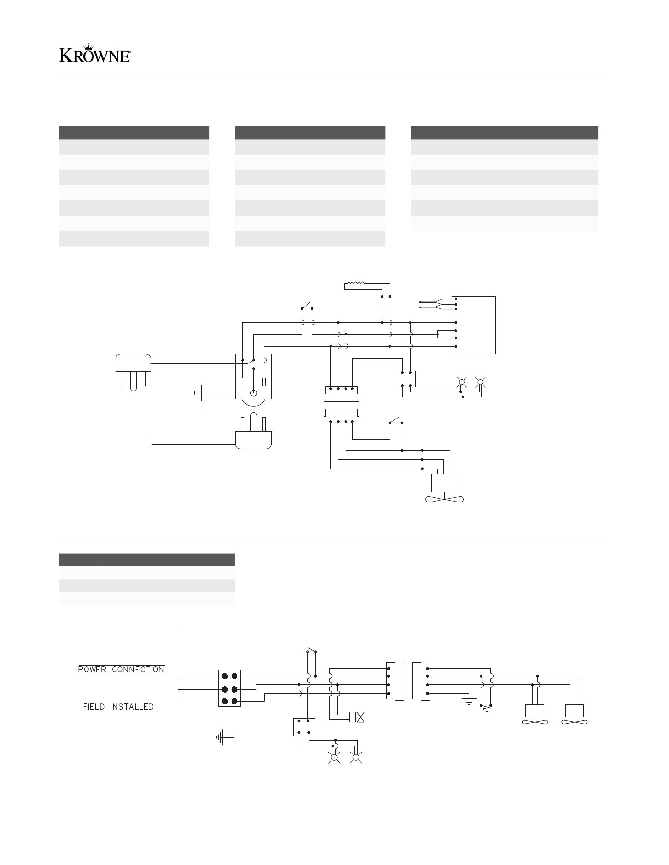
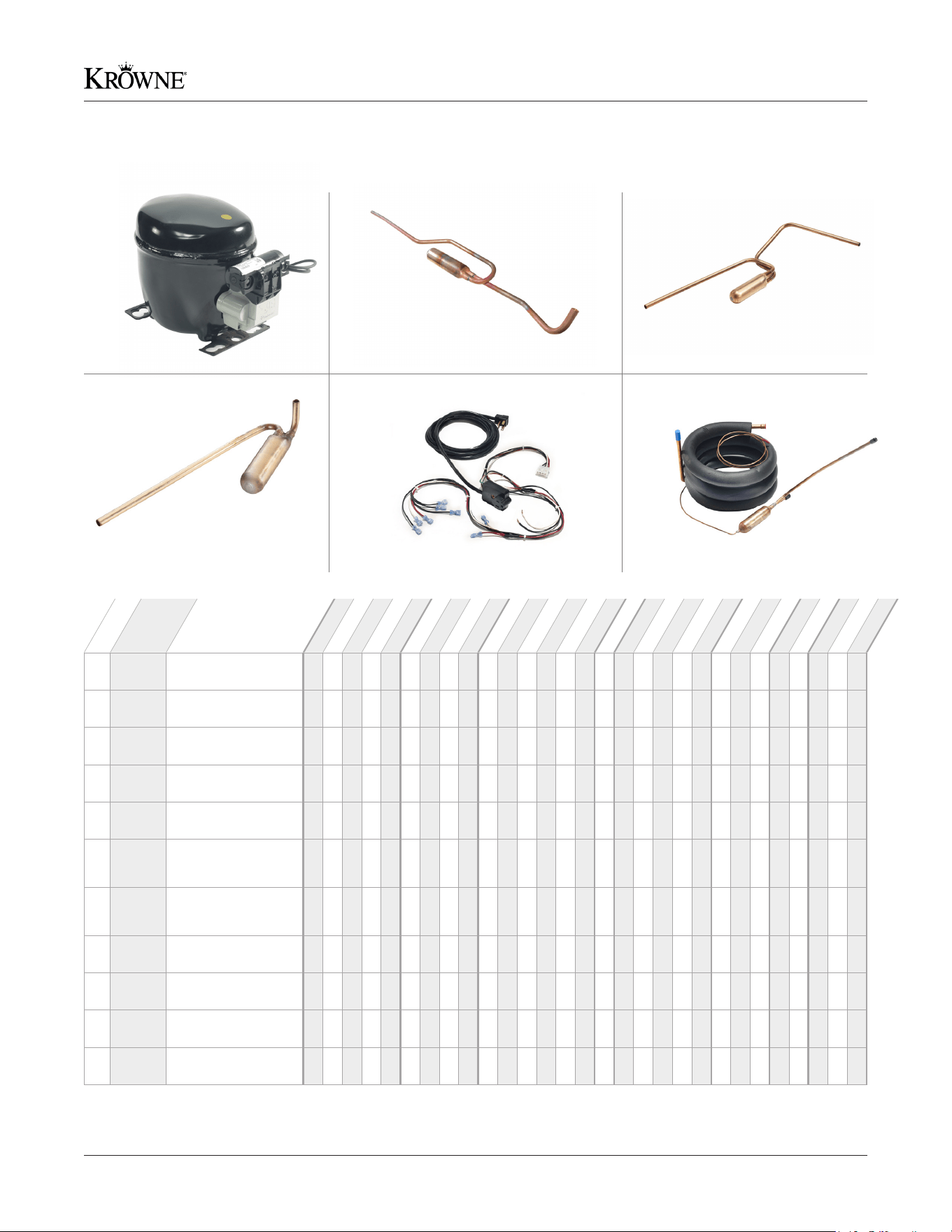
Slide Top Mug Frosters
All units are 115V, 1 Phase, 60 Hz
Front Door Mug Frosters
All units are 115V, 1 Phase, 60 Hz
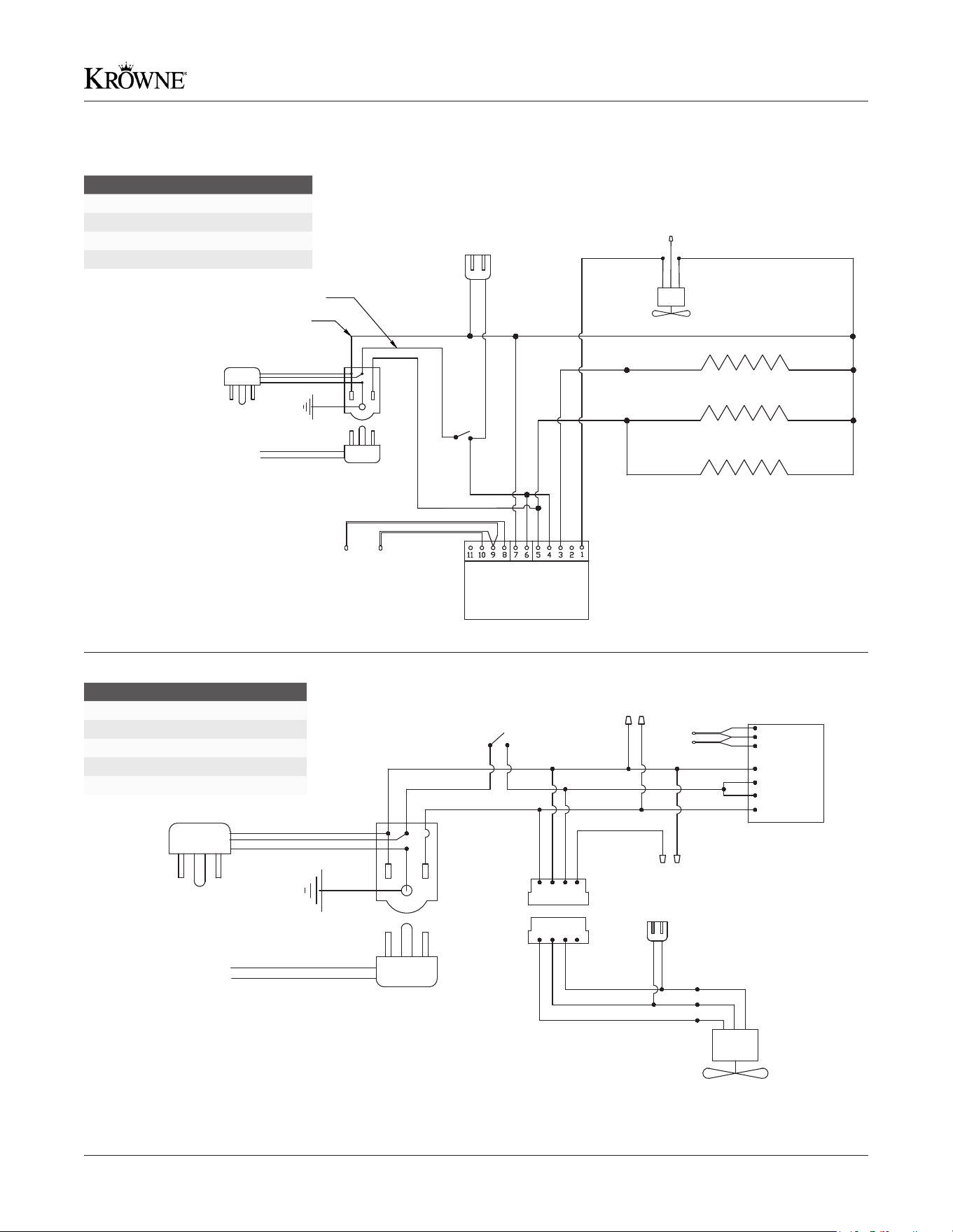
Bottle Coolers
All units are 115V, 1 Phase, 60 Hz
7Krowne • 100 Haul Rd. Wayne, NJ 07470 • krowne.com
Refrigeration Installation & Operating Manual
Model Description
BS36 36” Back Bar Cooler
BS60 60” Back Bar Cooler
BS84 84” Back Bar Cooler
BS108 108” Back Bar Cooler
DB36 36” Direct Draw Cooler
DB52 52” Direct Draw Cooler
DB60 60” Direct Draw Cooler
Model Description
DB72 72” Direct Draw Cooler
DB84 84” Direct Draw Cooler
DB108 108” Direct Draw Cooler
KPT36 36” Pass Thru Cooler
KPT52 52” Pass Thru Cooler
KPT60 60” Pass Thru Cooler
KPT72 72” Pass Thru Cooler
Model Description
KPT84 84” Pass Thru Cooler
NS52 52” Narrow Door Back Bar Cooler
NS72 72” Narrow Door Back Bar Cooler
PTSD60 60” Sliding Door Pass Thru Cooler
SD60 60” Sliding Door Back Bar Cooler
SD108 108” Sliding Door Back Bar Cooler
Model Description
BR48 48” Remote Back Bar Cooler
BR72 72” Remote Back Bar Cooler
BR96 96” Remote Back Bar Cooler
PLUG-IN-CORD
115 VOLTS 15 AMPS RECOMMENDED
TO THE CONDENSING UNIT
EVAPORATOR FAN MOTOR, 2 SPEED(BS36 BLACK
WIRE NOT CONNECTED TO RED (1 SPEED))
BLACK
WHITE
RED
BLACK
BLACK
BROWN BROWN
WHITE
RED BLACK
BLUE
LED LIGHTS
(2 PER DOOR)
RED (+DC)
BLACK (-DC)
12VDC
LED
POWER
SUPPLY
LIGHT SWITCH
TEMPERATURE
PROBE
8
9
7
6
4
3
DIGITAL
TEMPERATURE
CONTROL
PIN&SOCKET
CONNECTOR
4 WIRE FEMALE
RECEPTACLE
PIN&SOCKET
CONNECTOR
4 WIRE MALE PLUG
GROUND
POWER SWITCH
10
DEFROST PROBE
MULLION HEATER( 1 PER POST)
EVAPORATOR FAN MOTORS
(3 MOTORS 96" MODEL)
LED LIGHTS
(2 PER DOOR)
RED (+DC)
BLACK (-DC)
LED
12VDC
POWER
SUPPLY
LIGHT SWITCH
GROUND
115VAC
Note:
Field wiring to the cabinet
and from the cabinet to the
condensing unit must comply with
all local and electrical codes
BLACK
WHITE
GROUND
CONNECTION BLOCK
(right/left side of
evaporator housing
remove cover)
WHITE
BLACK
GREEN
PURPLE
SOLENOID
VALVE (IF USED)
RED
PIN & SOCKET CONNECTOR 4
WIRE FEMALE RECEPTACLE
PIN & SOCKET CONNECTOR 4
WIRE MALE PLUG
MECHANICAL
THERMOSTAT (IF USED)
RED
BLACK
WHITE
GREEN
Wire Diagrams
8 Krowne • 100 Haul Rd. Wayne, NJ 07470 • krowne.com
Refrigeration Installation & Operating Manual
DIGITAL
TEMPERATURE
CONTROL
BOX
TEMP
SENSOR
TO THE CONDENSING
UNIT
(RED)
110V PLUG-IN CORD
POWER BLACK
NEUTRAL
WHITE
LIGHT CONNECTION
(OPTIONAL)
(WHITE)
(BLACK)
POWER
SWITCH
(BLACK)
EVAP
DEFROST
SENSOR
(BLUE)
CENTER PIECE MULLION HEATER
(ONLY ON 48” UNITS)
FRAME MULLION HEATER
EVAPORATOR DEFROST HEATER
(RED)
(YELLOW)
(BLUE)
(WHITE)
EVAPORATOR FAN
(BLUE)
(BLACK)
(BROWN)
PLUG-IN-CORD
115 VOLTS 15 AMPS RECOMMENDED
TO THE CONDENSING UNIT
EVAPORATOR FAN MOTOR, 2 SPEED(2 MOTORS BC96
MODEL, BC24 AND BC36 MODELS BLACK WIRE NOT
CONNECTED TO RED (1 SPEED))
BLACK
WHITE
RED
BLACK
BROWN
WHITE BLUE
BLACK BLACK
TEMPERATURE
PROBE
8
9
7
6
4
3
DIGITAL
TEMPERATURE
CONTROL
PIN & SOCKET
CONNECTOR
4 WIRE FEMALE
RECEPTACLE
PIN & SOCKET
CONNECTOR
4 WIRE MALE PLUG
GROUND
BOTTLE COOLERS
1,2 AND 3 Door
POWER SWITCH
10
DEFROST PROBE
BROWN
LIGHT CONNECTION
(OPTIONAL)
Model Description
MC24 24” Slide Top Mug Froster
MC36 36” Slide Top Mug Froster
MC48 48” Slide Top Mug Froster
FMC24 24” Front Door Mug Froster
Model Description
BC24 24” Slide Top Bottle Cooler
BC36 36” Slide Top Bottle Cooler
BC48 48” Slide Top Bottle Cooler
BC72 72” Slide Top Bottle Cooler
BC96 96” Slide Top Bottle Cooler
Wire Diagrams
9Krowne • 100 Haul Rd. Wayne, NJ 07470 • krowne.com
Refrigeration Installation & Operating Manual
1A, 1B, 1C
4A, 4B
2
5
3
6A, 6B, 6C
1A BC-755
Compressor Head,
R290 (Propane) 1/6 HP
1B BC-756
Compressor Head,
R290 (Propane) 1/3 HP
1C BC-757
Compressor Head,
R290 (Propane) 1/4 HP
2 BC-668
Mug Froster
Accumulator Assembly
3 BC-669
Bottle Cooler
Accumulator Assembly
4A BC-766
Back Bar Accumulator
Assembly for Left
Side Compressors
4B BC-767
Back Bar Accumulator
Assembly for Right
Side Compressors
5 BC-772
Wire Harness Power
Supply
6A BC-670*
Suction Line &
Cap Tube Assembly
6B BC-671*
Suction Line &
Cap Tube Assembly
6C BC-683
Suction Line &
Cap Tube Assembly
No.
Model
Desc.
BC24
BC36
BC48
BC72
BC96
BS36
BS60
BS84
BS108
DB36
DB52
DB60
DB72
DB84
DB108
FMC24
KPT36L
KPT52L
KPT60L
KPT72L
KPT84L
MC24
MC36
MC48
NS52
NS72
PTSD60
SD60
SD108
*Note: When ordering BC-670 and BC-671, please specify the compressor side of your unit so correct part is shipped.
Replacement Parts - Compressor Housing
10 Krowne • 100 Haul Rd. Wayne, NJ 07470 • krowne.com
Refrigeration Installation & Operating Manual
1A, 1B 2A, 2B
9A, 9B8A, 8B7A, 7B, 7C
3A, 3B 4A, 4B 5
6
Note: BC96 uses (2) 33” Sliding Doors (BC-712 or BC-713) and (1) 21” Sliding Door (BC-710 or BC-711)
1A BC-700 Black Vinyl Door
1B BC-694
Black Vinyl Door
(Narrow)
2A BC-701 Stainless Steel Door
2B BC-697
Stainless Steel Door
(Narrow)
3A BC-705
Glass Door with
Black Vinyl
3B BC-695
Glass Door with
Black Vinyl (Narrow)
4A BC-706
Glass Door with
Stainless Steel
4B BC-698
Glass Door with
Stainless Steel
(Narrow)
5 BC-715
Stainless Steel Door
for Mug Frosters
6 BC-716
Black Vinyl Door
for Mug Frosters
7A BC-552
Door Gasket for
Regular Doors
7B BC-553
Door Gasket for
Narrow Doors
7C BC-657 Door Gasket for FMC
8A BC-710
21” Sliding Door
with Lock
8B BC-712
33” Sliding Door
with Lock
9A BC-711
21” Sliding Door
(no lock)
9B BC-713
33” Sliding Door
(no lock)
No.
Model
Desc.
BC24
BC36
BC48
BC72
BC96
BR48
BR72
BR96
BS36
BS60
BS84
BS108
DB36
DB52
DB60
DB72
DB84
DB108
FMC24
KPT36L
KPT52L
KPT60L
KPT72L
KPT84L
MC24
MC36
MC48
NS52
NS72
Replacement Parts - Locks, Handles & Doors
11Krowne • 100 Haul Rd. Wayne, NJ 07470 • krowne.com
Refrigeration Installation & Operating Manual
10
16A, 16B
11 12 13
18
14
19
15
20
17A, 17B,
17C, 17D, 17E
Note: BC-590 - Bottom Door Hinge and BC-591 - Top Door Hinge (Spring Loaded) are included with doors.
10 BC-619
Door Lock Assembly
for Bottle Coolers &
Mug Frosters
11 BC-828
Back Bar Door
Handle Full Assembly
12 BC-789
Back Bar Door
Handle Lock
13 BC-816
Back Bar Door
Handle Top
14 BC-817
Back Bar Door
Handle Bottom
15 BC-830
Back Bar Door
Handle Tube
16A 1575
Top Door Support
Bracket
16B 1576
Top Door Support
Bracket (Narrow)
17A BC-608
24” Gasket for
Bottle Coolers &
Mug Frosters
17B BC-609
36” Gasket for
Bottle Coolers &
Mug Frosters
17C BC-610
48” Gasket for
Bottle Coolers &
Mug Frosters
17D BC-611
72” Gasket for
Bottle Coolers &
Mug Frosters
17E BC-612
96” Gasket for
Bottle Coolers &
Mug Frosters
18 BC-590 Bottom Door Hinge
19 BC-591
Top Door Hinge
(Spring Loaded)
20 BC-592
Zinc Plated
L-Bracket
No.
Model
Desc.
BC24
BC36
BC48
BC72
BC96
BR48
BR72
BR96
BS36
BS60
BS84
BS108
DB36
DB52
DB60
DB72
DB84
DB108
FMC24
KPT36L
KPT52L
KPT60L
KPT72L
KPT84L
MC24
MC36
MC48
NS52
NS72
Replacement Parts - Locks, Handles & Doors
12 Krowne • 100 Haul Rd. Wayne, NJ 07470 • krowne.com
Refrigeration Installation & Operating Manual
1
5
2
6
3
7A, 7B 8
4
1 BC-760 Fan Blade
2 BC-761* Fan Motor
3 BC-776 Fan Guard
4 BC-788
Evaporator Fan
Assembly
5 BC-774 LED Power Supply
6 BC-598 LED Converter
7A BC-814 Power Switch
7B BC-814 Light Switch
8 BC-100
Bottle Cooler LED
Interior Light Kit
9A 2164**
White LED Light
Assembly for
Standard Doors
9B 2165**
White LED Light
Assembly for
Narrow Doors
10 BC-823**
Warm White LED
Light Assembly
(3500K)
11 BS-500**
Blue LED Light
Assembly
No.
Model
Desc.
BC24
BC36
BC48
BC72
BC96
BR48
BR72
BR96
BS36
BS60
BS84
BS108
DB36
DB52
DB60
DB72
DB84
DB108
FMC24
KPT36L
KPT52L
KPT60L
KPT72L
KPT84L
MC24
MC36
MC48
NS52
NS72
PTSD60
SD60
SD108
*Note: BC-761 is also used as an Evaporator motor for BC, FMC, and MC units.
**Note: Light Assemblies are designed on a per door basis. For example, a 2-Door unit requires (2) Light Assemblies.
9A, 9B 10 11
Replacement Parts - Mechanical & Lighting
13Krowne • 100 Haul Rd. Wayne, NJ 07470 • krowne.com
Refrigeration Installation & Operating Manual
1A, 1B, 1C
5A, 5B
2A, 2B, 2C, 2D
6
3A, 3B, 3C, 3D
7 8
4A, 4B, 4C
1A BC-557 Evaporator Coil
1B BC-558 Evaporator Coil
1C BC-519 Evaporator Coil
2A BC-630 Evaporator Coil
2B BC-502 Evaporator Coil
2C BC-503 Evaporator Coil
2D BC-504 Evaporator Coil
3A BC-505 Evaporator Coil
3B BC-506 Evaporator Coil
3C BC-507 Evaporator Coil
3D BC-822 Evaporator Coil
4A BC-513
Thermostat Sensor
for Mug Frosters
4B BC-537
Thermostat Sensor
for Back Bar
4C BC-517
Thermostat Sensor
(Long)
5A BC-509
Digital Thermostat
for Mug Frosters
5B BC-535 Digital Thermostat
6 BC-655
Evaporator Defrost
Heater (Mug Frost-
ers)
7 BC-627 Condenser Coil
8 BC-642 Condenser Coil
No.
Model
Desc.
BC24
BC36
BC48
BC72
BC96
BR48
BR72
BR96
BS36
BS60
BS84
BS108
DB36
DB52
DB60
DB72
DB84
DB108
FMC24
KPT36L
KPT52L
KPT60L
KPT72L
KPT84L
MC24
MC36
MC48
NS52
NS72
PTSD60
SD60
SD108
Replacement Parts - Temperature Control
14 Krowne • 100 Haul Rd. Wayne, NJ 07470 • krowne.com
Refrigeration Installation & Operating Manual
1A, 1B, 1C, 1D, 1E, 1F, 1G, 1H
4
2
5A, 5B, 5C, 5D
3
6A, 6B, 6C 7
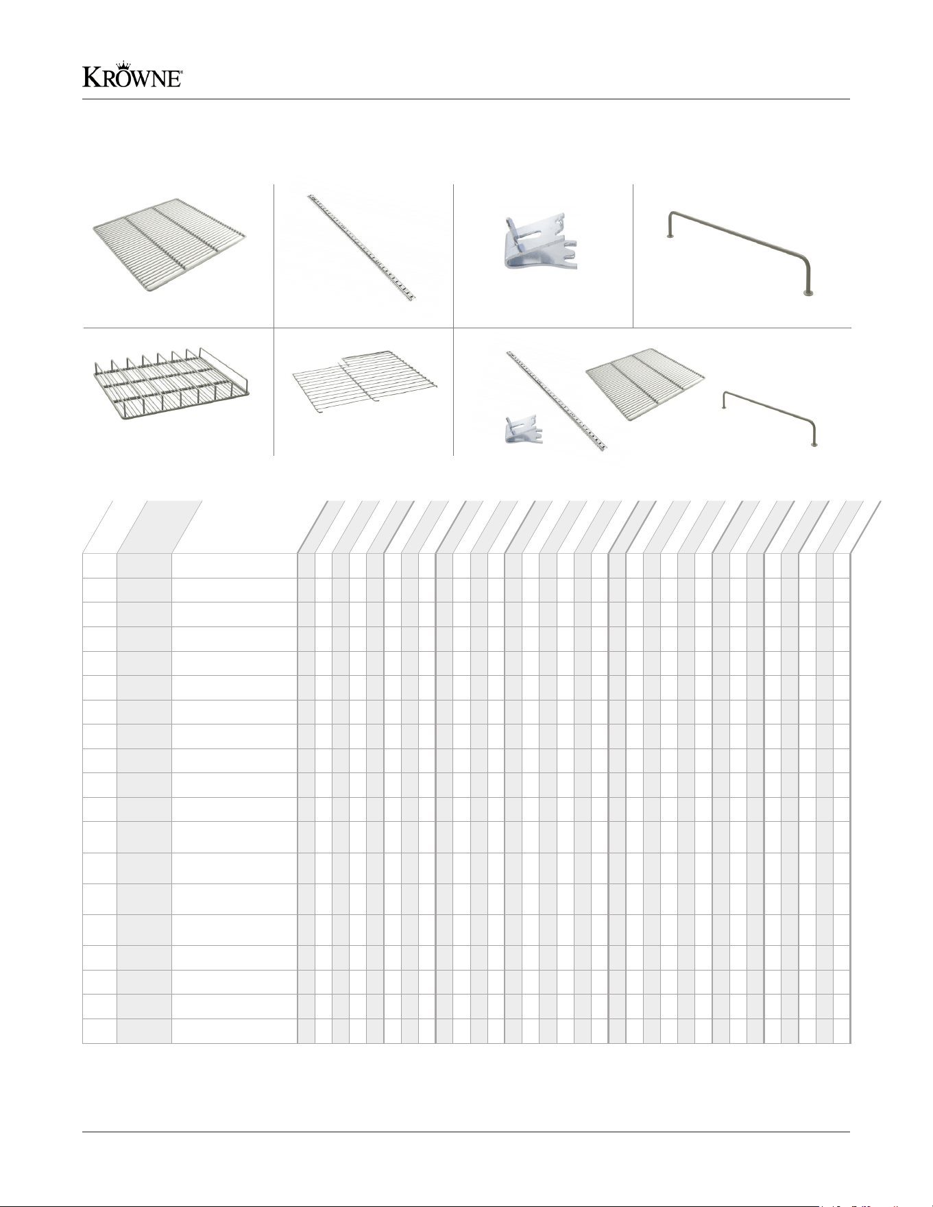
1A BC-538 21-5/8” x 18” Shelf
1B BC-539 23-5/8” x 18” Shelf
1C BC-647 7” x 19-3/4” Shelf
1D BC-648 19-¼” x 19-¾” Shelf
1E BC-649 12” x 19-3/4” Shelf
1F BC-650 15” x 19-3/4” Shelf
1G BC-747 17-5/8” x 18” Shelf
1H BC-748 19-5/8” x 18” Shelf
2
T22-0018
Pilaster (18”)
3 30-317 Pilaster Clip
4 BC-811 Side Guard Rail
5A BC-496
Shelf w/ Bottle
Dividers (L or R Door)
5B BC-497
Shelf w/ Bottle
Dividers (Center Door)
5C BC-485
Shelf w/ Bottle Dividers
(L or R Narrow Door)
5D BC-499
Shelf w/ Bottle Dividers
(Center Narrow Door)
6A BC-536 Wire Partition
6B BC-540 Wire Partition
6C BC-541 Wire Partition
7 BC-498* Back Bar Shelving Kit
No.
Model
Desc.
BC24
BC36
BC48
BC72
BC96
BR48
BR72
BR96
BS36
BS60
BS84
BS108
DB36
DB52
DB60
DB72
DB84
DB108
FMC24
KPT36L
KPT52L
KPT60L
KPT72L
KPT84L
MC24
MC36
MC48
NS52
NS72
PTSD60
SD60
SD108
*Note: BC-498 is a Back Bar Shelving Kit designed for Direct Draw Coolers in which one door section requires shelving.
The Kit contains 30-317 - Pilaster Clip (qty. 12), T22-0018 - Pilaster (18”) (qty. 4), BC-811 - Side Guard Rail (qty. 3), and shelves for the specied unit (qty. 3).
Replacement Parts - Shelving
15Krowne • 100 Haul Rd. Wayne, NJ 07470 • krowne.com
Refrigeration Installation & Operating Manual
1
7
13A, 13B
2
8
14
3
9
15
4
10
16
5A, 5B, 5C, 5D, 5E
11
17
6B
6A
12A, 12B
18
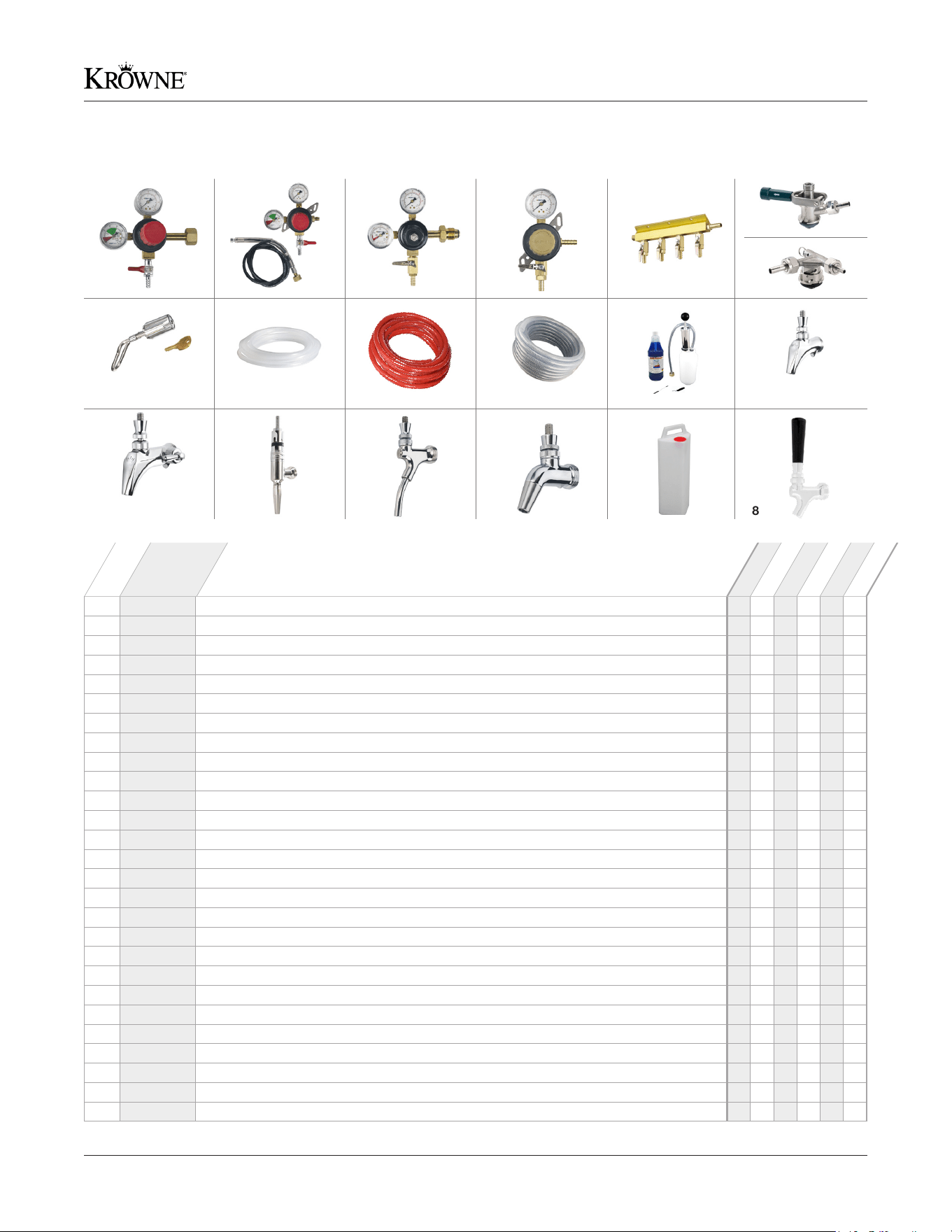
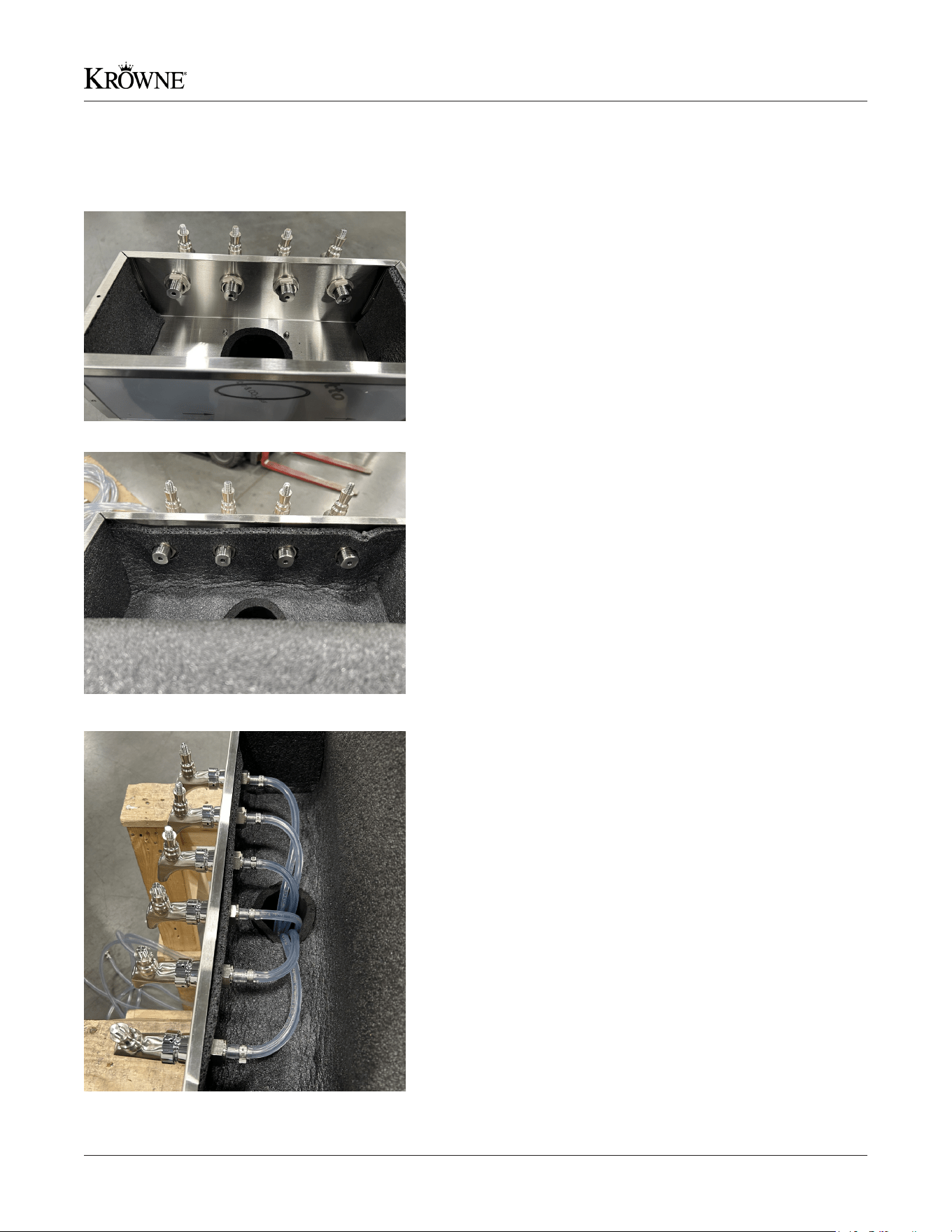
1 BC-792 CO2 Tank Mount Primary Regulator
2 BC-793 CO2 Tank Mount Primary Bulk Regulator
3 BC-794 CO2 Tank Mount Primary Nitrogen Regulator
4 BC-843 CO2 Tank Mount Secondary Regulator
5A BC-795 2-Way Manifold
5B BC-796 3-Way Manifold
5C BC-797 4-Way Manifold
5D BC-798 5-Way Manifold
5E BC-799 6-Way Manifold
6A BC-932 Sankey Keg Tap, Stainless Steel Probe for Domestic Kegs (D System)
6A BC-933 Sankey Keg Tap, Stainless Steel Probe for Import Kegs (S System)
6B BC-936 Low Prole Sankey Keg Tap, Stainless Steel Probe for Domestic Kegs (D System)
6B BC-937 Low Prole Sankey Keg Tap, Stainless Steel Probe for Import Kegs (S System)
7 BC-801 Beer Faucet Lock
8 BC-802 1/2” ID Clear Vinyl Drain Line (For Drip Pan Drain)
9 BC-803 5/16” ID Nylon Braided Air Line (Regulator to Manifold)
10 BC-804 5/16” ID Nylon Braided Air Line (Manifold to Keg Tap)
11 BC-805 Line Cleaning Kit
12A BC-300 Royal Series Standard Beer Faucet (Satin Finish)
12B BC-900 Royal Series Standard Beer Faucet (Stainless Finish)
13A BC-325 Royal Series Flow Control Beer Faucet (Satin Finish)
13B BC-925 Royal Series Flow Control Beer Faucet (Stainless Finish)
14 BC-806 Nitro Faucet, for Stouts and Coffee
15 BC-808 Wine Faucet with Long Spout
16 BC-812 Intertap Forward Sealing High-Performance Faucet
17 BC-824 Drain Container - 4 gallon capacity
18 BC-807 Standard Black Tap Handle
No.
Model
Desc.
DB36
DB52
DB60
DB72
DB84
DB108
Direct Draw Coolers Parts & Accessories
16 Krowne • 100 Haul Rd. Wayne, NJ 07470 • krowne.com
Refrigeration Installation & Operating Manual
31
4
2
5
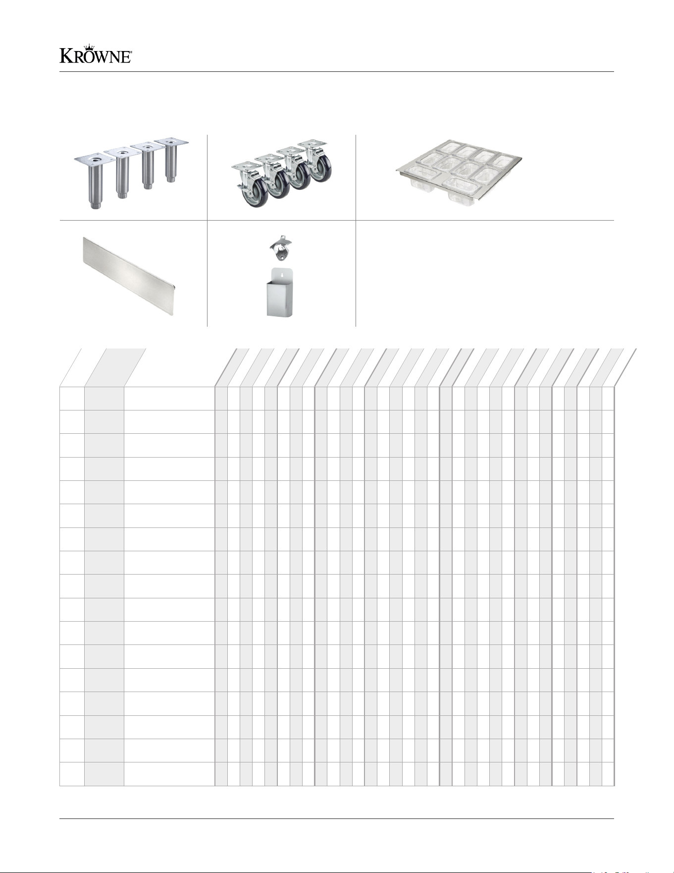
1A BS-100
6” Stainless Steel
Legs (Set of 4)
1B BS-101
6” Stainless Steel
Legs (Set of 6)
1C BS-102
4” Stainless Steel
Legs (Set of 4)
1D BS-103
4” Stainless Steel
Legs (Set of 6)
2A BC-130
2” Overall Casters
(1” Wheels, Set of 4)
2B BC-131
2” Overall Casters
(1” Wheels, Set of 6)
2C BC-132
3” Overall Casters
(2” Wheels, Set of 4)
2D BC-133
3” Overall Casters
(2” Wheels, Set of 6)
2E BC-134
4” Overall Casters
(3” Wheels, Set of 4)
2F BC-135
4” Overall Casters
(3” Wheels, Set of 6)
2G BC-136
5” Overall Casters
(4” Wheels, Set of 4)
2H BC-137
5” Overall Casters
(4” Wheels, Set of 6)
2I BC-138
6” Overall Casters
(5” Wheels, Set of 4)
2J BC-139
6” Overall Casters
(5” Wheels, Set of 6)
3 BD-101
Garnish Insert for
Drawers
4 BD-102
(3) Adjustable Wine
Dividers for Drawers
5 BC-111
Bottle Opener and
Cap Catcher
No.
Model
Desc.
BC24
BC36
BC48
BC72
BC96
BR48
BR72
BR96
BS36
BS60
BS84
BS108
DB36
DB52
DB60
DB72
DB84
DB108
FMC24
KPT36L
KPT52L
KPT60L
KPT72L
KPT84L
MC24
MC36
MC48
NS52
NS72
PTSD60
SD60
SD108
Legs & Casters Installation Note:
Avoid turning unit on its side or rear to install accessories.
If this cannot be avoided, unit must be left in the upright
position for 24 hours before operating. All units come
equipped with predetermined mounting holes and self
starting bolts for easy install (bolts are provided only when
casters or legs are ordered from factory). It is important
to check that casters or legs are securely attached with
appropriate mounting hardware.
Legs, Casters, and Accessories
17Krowne • 100 Haul Rd. Wayne, NJ 07470 • krowne.com
Refrigeration Installation & Operating Manual
Problem Cause Solution
There is no interior
light on in the
refrigeration unit.
Light switch is in OFF position. Flip switch to ON.
LED board is inoperable. Contact your dealer.
Refrigeration unit is
running noisy.
Soft sounds from compressor, fan motor
& valves.
Normal operation.
Refrigeration unit is
not running correctly.
No power is getting to the unit.
GFI is tripped or the circuit breaker is tripped.
Reset the circuit breaker.
The compartments are
warmer than usual in
the refrigeration unit.
Control preset is not set properly. Reset preset temperature if necessary
Condenser is dirty or obstructed. Clean condenser and clear obstruction.
Door has been left open for an extended
period of time.
Wait 24 hours and recheck temperature.
Internal louvers and/or fan guard obstructed. Ensure louvers and/or fan is not obstructed.
Warm product was placed in the unit. Remove warm product and wait 24 hours.
Refrigeration system
runs for long period
of time.
Condenser is dirty or obstructed. Clean condenser and clear obstruction.
Door has been left open for an extended
period of time.
Wait 24 hours and recheck temperature.
Warm product was placed in the unit. Remove warm product and wait 24 hours.
Hot day and/or warm room temperature. Normal for system to run more frequently.
Condensation forms
on the inside of the
compartments.
High humidity and/or frequent door opening. Normal operation.
Door not closing and sealing properly.
Ensure door is closing properly. Check door
seals and replace if necessary. If condensation
persists, contact your dealer.
Condensation forms
on the outside of the
compartments.
High humidity and/or frequent door opening. Normal operation.
Door not closing and sealing properly.
Make sure door is closing properly. Check door
seals and replace if necessary. If condensation
persists, contact your dealer.
Thermostat ashing
the word “OFF” and
the temperature.
The compressor was turned off.
Hold the power button for 3 seconds and the
compressor will turn back on.
Before calling for service, please use this table to troubleshoot your issue.
Troubleshooting
18 Krowne • 100 Haul Rd. Wayne, NJ 07470 • krowne.com
Refrigeration Installation & Operating Manual
Top Bracket
Handle Rod
Key
Lock
Bottom Bracket
Tools Required: Phillips Head Screwdriver
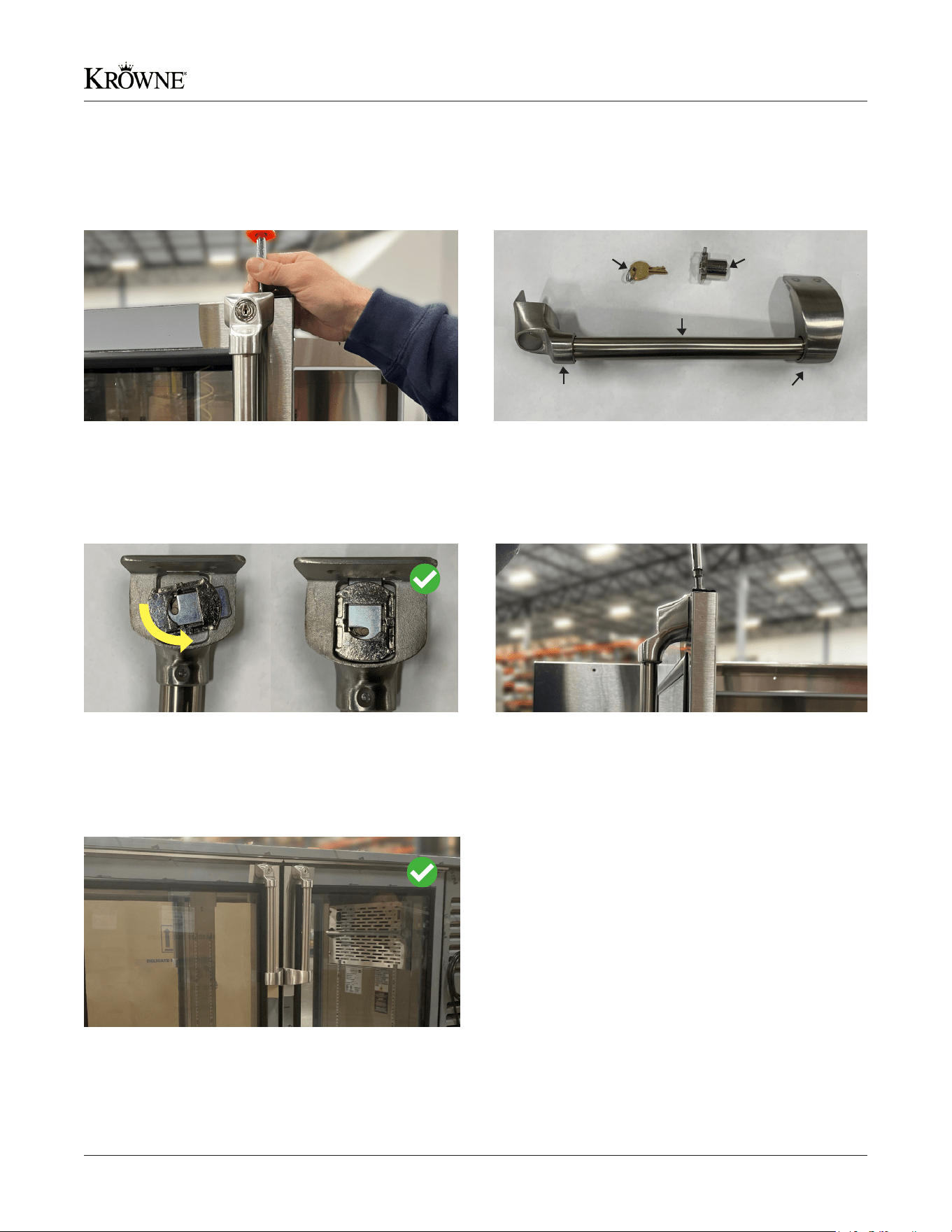
1. Remove the eight 32 x 1/2” Phillips head screws located
on the top and bottom bracket of your existing door
handle. Remove the handle and set the screws aside.
These screws will be used on the new handle.
2. Assemble your new handle by sliding the handle rod into
the bottom bracket and top bracket.
3. Insert the lock at an angle into the slot on the backside
of the top bracket. Turn the lock counter clockwise until
it falls into place. Make sure the lock is positioned facing
down as pictured.
4. Position the new handle by aligning the top bracket with
the holes on the top of the door. Secure with existing
screws.
5. Align the bottom bracket with the holes on the side of
the door. Secure with existing screws. Repeat steps for
additional handles.
Changing a Door Handle
19Krowne • 100 Haul Rd. Wayne, NJ 07470 • krowne.com
Refrigeration Installation & Operating Manual
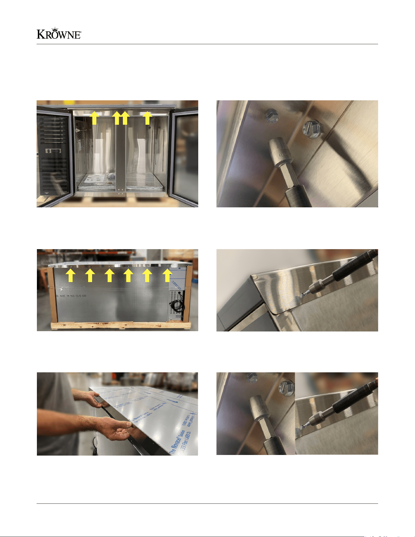
Tools Required: 1/4” Hex Screwdriver
2. Remove the 1/4” hex screws on the front of the unit
above the doors. Set the screws aside. These will be
used on the new refrigeration top.
4. Remove the 1/4” hex screws on the back of the unit.
Set the screws aside. These will be used on the new
refrigeration top.
3. Locate the 1/4” hex screws on the back of the unit.
5. With 2 or more people, lift the existing stainless steel top
off and set aside. Next, place the new stainless steel top
on your unit.
1. Locate the 1/4” hex screws on the front of the unit.
6. Secure the new top by screwing in the hex screws on the
back and front of the unit.
Changing a Stainless Steel Top
20 Krowne • 100 Haul Rd. Wayne, NJ 07470 • krowne.com
Refrigeration Installation & Operating Manual
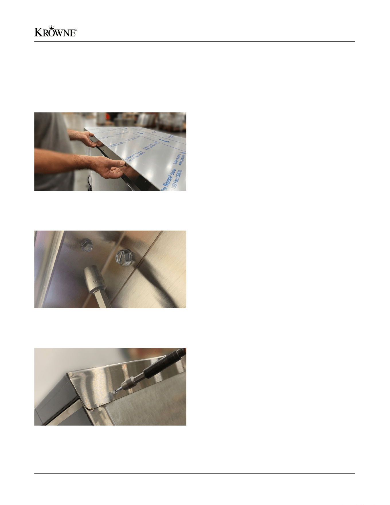
Tools Required: 1/4” Hex Screwdriver
3. On the back of the unit, screw the supplied 1/4” hex
screws into the pre-existing holes to fully secure the
stainless steel top.
1. With two or more people, open the crate and carefully
remove the stainless steel top. Do not discard the 1”
foam insert. The 1” foam insert will be placed inside
the stainless steel top. With two or more people, lift the
stainless steel top and place on top of the unit.
2. On the front of the unit, open the doors. Use the supplied
1/4” hex screws to secure the front of the stainless steel
top to the door hinge.
Installing a New Stainless Steel Top
21Krowne • 100 Haul Rd. Wayne, NJ 07470 • krowne.com
Refrigeration Installation & Operating Manual
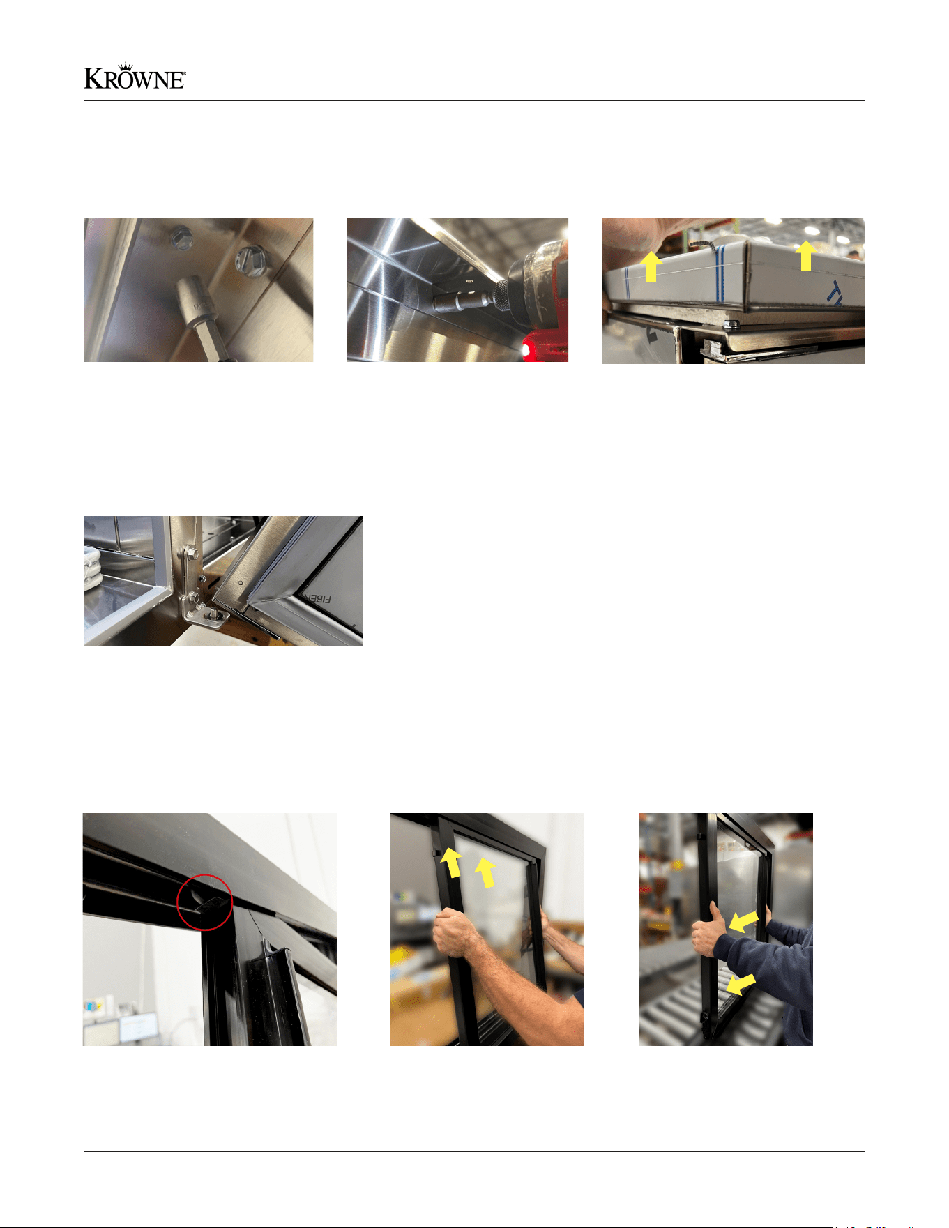
1. Locate hex screws on the
underside of the stainless steel
top and unscrew with a 1/4” hex
screwdriver. (Skip steps 1-3 if
your unit has an unnished top)
3. Once all hex screws are removed,
lift stainless steel top up to remove.
CAUTION: When the top is removed,
the door(s) should pull away and drop
rapidly. We recommend having 2 or
more people assist with this step.
2. Unscrew the (3) 3/8” hex screws
that are located on the top frame
of each door using a 3/8” hex
screwdriver.
1. Locate the spring on the top frame of
your refrigeration unit.
2. Insert the top half into the
frame. Make sure the spring
is pulled back with the door.
3. Apply pressure and push
the bottom half in until you
hear it snap into place.
4. For unfinished top units: Align new door with the bottom hinge
and re-screw the top (3) 3/8” hex bolts to secure the door.
For stainless steel top units: Align new door with the bottom
hinge and re-screw the top (3) 3/8” hex bolts to secure the door.
Place the stainless steel top back onto the unit and secure with
the 1/4” hex bolts.
Tools Required: 1/4” Hex Screwdriver & 3/8” Hex Screwdriver
Tools Required: None
Changing a Swing Door
Changing a Sliding Door
22 Krowne • 100 Haul Rd. Wayne, NJ 07470 • krowne.com
Refrigeration Installation & Operating Manual
1. Power down the unit. After the unit is off, remove the (4)
1/4” hex screws to remove the existing light.
2. Remove light and cut off both wire caps
3. Reconnect wires with wires from the new light. Red to
red, black to black. Reattach the electrical connector to
the new wires.
4. Put all the screws back. Ensure wires are not pinched
under new brackets.
1. Remove shelving.
Locate the pilaster clip
and apply pressure to
the bottom of the clip
and slide out to remove.
2. Align clips to desired
height by using the
numbered slots on the
pilaster strips. Adjust all
clips to the same number
on the pilaster strips.
4. Repeat until all other
clips are secured in their
slots. Place your shelves
onto clips.
3. Insert the top part of the
clip into the slot and apply
pressure to the bottom
half of the clip until the
clip snaps into place.
Tools Required: 1/4” Hex Screwdriver
Tools Required: None
Changing LED Lights
Adjusting Shelving
23Krowne • 100 Haul Rd. Wayne, NJ 07470 • krowne.com
Refrigeration Installation & Operating Manual
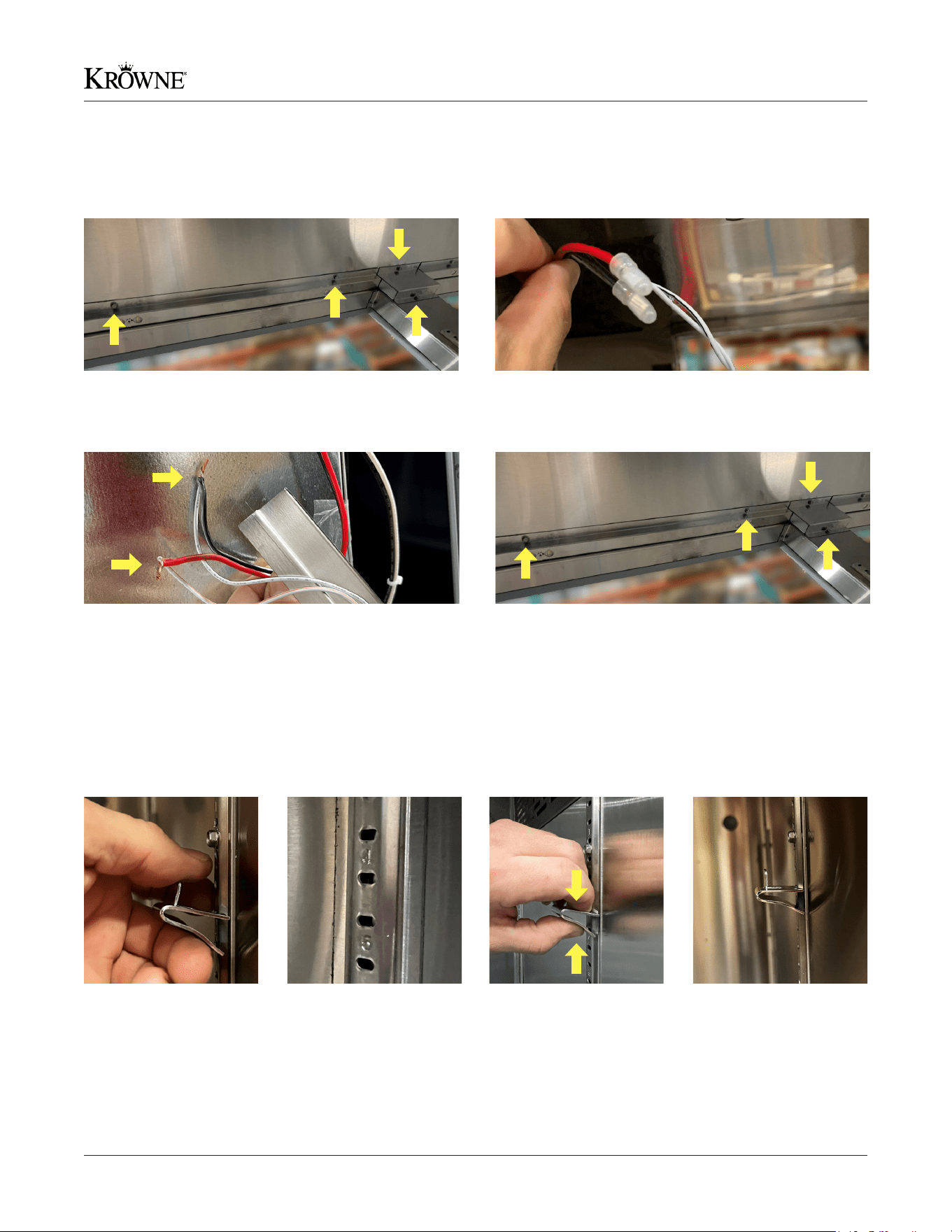
Installing Dispensing Faucets
1. Remove 1-1/8” nut from shank. Insert the shank into the
corresponding hole on the tower.
2. Install the nut onto the shank inside the tower. Install the
faucet onto the shank and tighten the nut inside the tower.
While doing this, make sure the faucets are straight or
aligned with each other.
4. Install a black insulation foam sheet into tower. Make sure
to insulate around the shank and the sides. Make sure to
pull the black round foam insulation up into the tower to
prevent air leaks.
5. Install beer lines and silicone washers (shank, washer,
tailpipe, beer line) onto shanks and tighten until snug.
Route the lines down into the column.
3. After all shanks are installed, used a spanner wrench
(Krowne model BC-902) to tighten the faucet onto the
shank itself.
24 Krowne • 100 Haul Rd. Wayne, NJ 07470 • krowne.com
Refrigeration Installation & Operating Manual
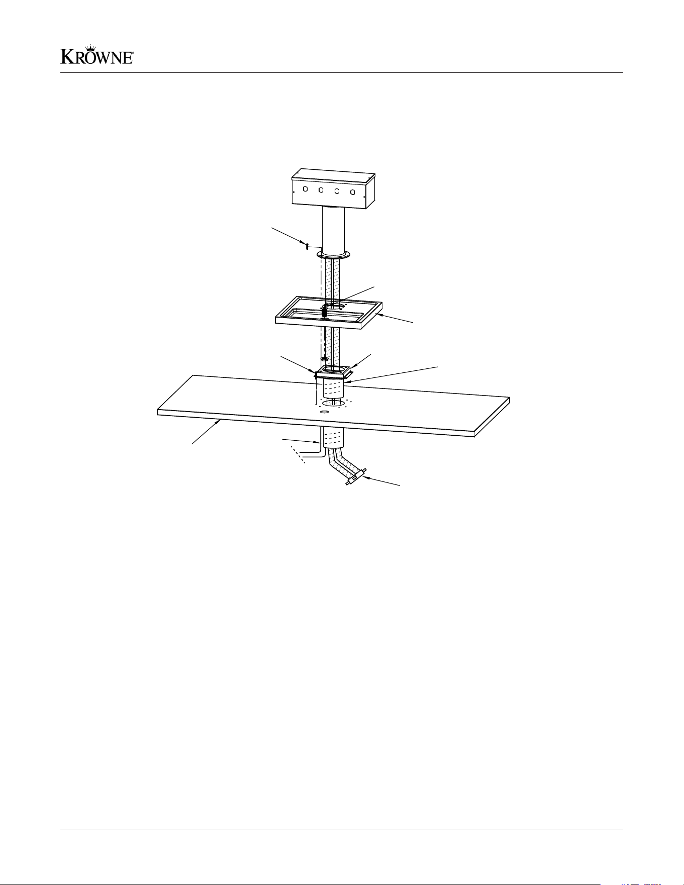
1. Cut out 3-3/4” holes in the counter top for the beer lines and 1-1/2” holes for the drip pan drain. Use the supplied drain
pan as a guide for hole locations.
2. Attach 1” tall square bracket to the countertop based on your application.
3. Cut black 4” round foam tube to length to insulate the area between the unit and the mounting bracket (through
countertop).
4. Attach gray hose to white 1” barb that is mounted inside the unit and up out of the countertop. Cut gray air hose to
required length – For 1 to 3 taps, the hose should be about 75% up into the tower. For 4 to 8 taps, the hose should be just
inside the “box” of taps.
5. Apply a small amount of silicone to at mating surface on the underside of pan to ensure no liquid gets between drain pan
and stainless top. This also results in better insulation. Set drain pan over the square bracket and align the four holes as
best as possible.
6. Feed the beer lines from the tower to the larger hole around the gray air hose.
7. Thread the attached straight 1/2” barb onto the drain that may still need to be mounted to the drain pan with silicone.
Tighten the supplied nut on the under side of the pan.
8. Cut the supplied clear drain hose to length to get it as close as possible to the top of the body to eliminate liquid traps in
the drain line.
9. Inside the unit, attach the 90° white 1/2” elbow to the drain line that is already installed in the unit.
10. Place the tower over the pan and apply the rubber gasket and (4) 10-32 counter sunk screws (screws are supplied).
Tools Required: Phillips Head Screwdriver, Silicone, & Mounting
Hardware according to Countertop
Installing Dispensing Towers
1” GREY AIR HOSE
CLEAR 1/2”
DRAIN HOSE
STONE OR WOOD
COUNTERTOP
SCREWS BASED
ON APPLICATION (8)
ARMAFLEX 3-1/8” OD X 3/8”
WALL X 6’ FLEXIBLE BLACK
TUBE INSULATION
5” X 5” X 1”
#10-32X.75
SS FLAT HEAD
SCREWS (4)
APPLY A GOOD BEAD
OF SILICONE UNDER THE DRIP TRAY
ALL THE WAY AROUND
1” DRAIN
25Krowne • 100 Haul Rd. Wayne, NJ 07470 • krowne.com
Refrigeration Installation & Operating Manual
(2) Two Year Parts & Labor Warranty
Parts Warranty
Any part found defective under normal use within two years of ship date will be replaced by Krowne. Warranty is void in the
absence of proper maintenance, operation and authorized service. Warranty is also void on units that have been damaged in
freight, eld altered, lack of proper electrical requirements, re, ood or natural disaster.
Defective Parts and Replacements
Must be returned to Krowne prepaid. Credit will be issued upon return and inspection of defective part.
Labor Warranty
Labor service MUST be approved by Krowne before work is done. If authorization is not obtained, warranty is void. Krowne is
not responsible for any loss of product or sales during that time. Any additional costs due to after hour services or excessive
travel time (more than an hour) will be incurred by end user. Labor warranty covers all 50 states.
Note: Parts, labor and compressor warranty applies to all commercial applications installed by a licensed installer. For
residential applications, we provide a two year parts warranty and ve year compressor warranty, however labor is not
covered in residential applications.
(5) Five Year Compressor Warranty
Compressor is covered by a 5 year replacement warranty and a 1 year labor warranty from the original factory ship date.
Condenser must be cleaned every 60 days or may void warranty. Warranty work must be authorized by factory prior to
service being done. Labor is not covered on the compressor replacement.
Remote Backbar Units
2 years parts, 1 year compressor (no labor).
All Krowne Metal Corporation refrigeration products are warranted to be free of defects in material and workmanship within
(2) two years of factory ship date. Visit krowne.com/warranty and register your product online. Registration must be complete
within (2) two weeks of install. Failure to do so may void labor warranty.
Certifications
Warranty

26 Krowne • 100 Haul Rd. Wayne, NJ 07470 • krowne.com
Refrigeration Installation & Operating Manual
This Standard Warranty and Limitation of Liability (the “Warranty”) sets forth the warranty provided by Krowne Metal Corporation (hereinafter “Krowne”) with respect to the product
purchased by Purchaser (the “Equipment). By accepting delivery of the Equipment, Purchaser agrees to be bound by and accept these terms and conditions. All defined terms
within the Warranty shall have the same meaning and definition as provided elsewhere in the Warranty. Equipment covered by the Warranty shall only be warranted in connec-
tion with its original installation only. KROWNE WILL ONLY BE OBLIGATED TO HONOR THE WARRANTY SET FORTH IN THESE TERMS AND CONDITIONS UPON RECEIPT OF FULL
PAYMENT FOR THE EQUIPMENT.
1. WARRANTY COVERAGE
A. Subject to the conditions and exclusions set forth below, including, with respect to Diamond
Series Plumbing, Purchaser’s completion and delivery to Krowne of a warranty registration card
or online Warranty registration, Krowne warrants to Purchaser that (i) Krowne holds and will pass
marketable title to the goods sold hereunder, and (ii) the goods sold hereunder will be free from
defects in materials and workmanship (subject to tolerances and variances permitted by the trade
hereunder) for the applicable Warranty Period, as listed above (the “Warranty Period”).
B. Krowne’s obligation under this Warranty is limited to, at Krowne’s option, replacing or repair-
ing, any Equipment or part thereof that is found by Krowne not to conform to the Equipment’s
specifications. Krowne shall have a reasonable period of time to make such replacements or
repairs and all labor associated therewith shall be performed during Krowne’s regular working
hours.
C. Krowne shall pay transportation charges for the return of any defective portion of the Equip-
ment. If returned Equipment is repaired or replaced under the terms of this Warranty, Krowne will
prepay transportation charges back to Purchaser; otherwise, Purchaser shall pay transportation
charges to return the Equipment back to the Purchaser. All returns must be pre-approved by
Krowne before shipment. Krowne shall not be obligated to pay freight for any unapproved return.
D. Any replacement parts or Equipment will be new, comparable in function and performance
to the original part of Equipment, and warranted for the remainder of the Warranty Period.
Purchasing additional parts or Equipment from Krowne does not extend this Warranty Period.
E. With regard to the Equipment, a defect shall refer to a variance from the design specifica-
tions that prohibit the Equipment from operating for its intended use. The Warranty provided by
Krowne does not impose any duty or liability upon Krowne for degradation that occurs in the
normal course over time, or due to improper installation of the Equipment by Purchaser or their
representative.
THIS LIMITED WARRANTY IS THE ONLY WARRANTY APPLICABLE TO THE EQUIPMENT AND
REPLACES ALL OTHER WARRANTIES OR CONDITIONS, EXPRESS OR IMPLIED, INCLUDING,
WITHOUT LIMITATION, THE IMPLIED WARRANTIES OR CONDITIONS OF MERCHANTABILITY
AND FITNESS FOR A PARTICULAR PURPOSE. SPECIFICALLY, EXCEPT AS PROVIDED HEREIN,
KROWNE UNDERTAKES NO RESPONSIBILITY FOR THE QUALITY OF THE EQUIPMENT OR THAT
THE EQUIPMENT WILL BE FIT FOR ANY PARTICULAR PURPOSE FOR WHICH PURCHASER MAY
BE BUYING THE EQUIPMENT. ANY IMPLIED WARRANTY IS LIMITED IN DURATION TO THE WAR-
RANTY PERIOD. NO ORAL OR WRITTEN INFORMATION, OR ADVICE GIVEN BY THE COMPANY, ITS
AGENTS OR EMPLOYEES, SHALL CREATE A WARRANTY OR IN ANY WAY INCREASE THE SCOPE
OF THIS LIMITED WARRANTY.
2. EXCLUSION FROM WARRANTY COVERAGE
The Warranty provided by Krowne does not impose any duty or liability upon Krowne for:
A. Any damage occurring, at any time, during shipping of Equipment unless otherwise provided
for in the Agreement. When returning Equipment to Krowne for repair or replacement, Purchaser
assumes all risk of loss or damage, and agrees to use any shipping containers that might be
provided by Krowne and to ship the Equipment in the manner prescribed by Krowne;
B. Damage caused by the failure to provide a continuously suitable environment, but not limited
to: (i) neglect or misuse, (ii) a failure or sudden surge of electrical power, (iii) improper air condi-
tioning or humidity control, or (iv) any other cause other than ordinary use;
C. Damage caused by the unauthorized installation, adjustment, repair or service of the Equip-
ment by anyone other than Krowne or Krowne’s expressly authorized designee;
D. Damage caused by fire, flood, earthquake, water, severe wind, lightning or other natural
disaster, strike, inability to obtain materials or utilities, war, terrorism, civil disturbance or any
other cause beyond Krowne’s reasonable control;
E. Failure to adjust, repair or replace any item of Equipment if it would be impractical for Krowne
personnel to do so because of connection of the Equipment by mechanical or electrical means to
another device not supplied by Krowne, or the existence of general environmental conditions at
the site that pose a danger to Krowne personnel;
F. Any statements made about the product by salesmen, dealers, distributors or agents, unless
such statements are in a written document signed by an officer of Krowne. Such statements
as are not included in a signed writing do not constitute warranties, shall not be relied upon by
Purchaser and are not part of the contract of sale;
G. Any damage arising from the use of Krowne products in any application other than the com-
mercial and industrial applications for which they are intended, unless, upon request, such use is
specifically approved in writing by Krowne; or
H. Any performance of preventive maintenance
3. PURCHASER’S INSPECTION UPON RECEIPT OF
EQUIPMENT
All Equipment shall be carefully inspected by Purchaser upon receipt, be installed by
persons who are trained and certified professionals with respect to such installations, and
be installed, used, repaired and maintained by Purchaser in accordance with all applicable
local laws, codes and regulations.
4. LIMITATION OF LIABILITY
In no event shall Krowne (including its subsidiaries, affiliates, officers, directors, employees,
or agents) be liable for any special, consequential, incidental or exemplary damages
arising out of or in any way connected with the Equipment or otherwise, including, without
limitation, to damages for lost profits, cost of substitute or replacement Equipment, down
time, lost data, injury to property or any damages or sums paid by Purchaser to third
parties, even if Krowne has been advised of the possibility of such damages. The foregoing
limitation of liability shall apply whether any claim is based upon principles of contract, tort
or statutory duty, principles of indemnity or contribution, or otherwise.
In no event shall Krowne be liable to Purchaser or any other party for loss, damage, or
injury of any kind or nature arising out of or in connection with this Warranty in excess of
the purchase price of the Equipment actually delivered to and paid for by the Purchaser.
The Purchaser’s remedy in any dispute under this Warranty shall be ultimately limited to
the Purchase Price of the Equipment to the extent the Purchase Price has been paid.
5. ASSIGNMENT OF RIGHTS
The Warranty contained herein extends only to the original Purchaser of the Equipment and
no attempt to extend the Warranty to any subsequent user or transferee of the Equipment
shall be valid or enforceable without the express written consent of Krowne. Any attempt
by Purchaser to assign this Warranty shall render the Warranty, but not any disclaimers or
limitations, void, and the goods shall be sold AS IS.
6. COMPONENT PASS THROUGH WARRANTY
Except as provided herein, although Krowne does not warrant components, it will pass
through any warranties received by third-party component suppliers, to the extent permit-
ted by the terms and conditions of such warranties.
7. NOTICE AND TIME OF CLAIMS
Purchaser shall make any claim for loss or damage to Equipment sustained during ship-
ment within five (5) days of receipt of such Equipment.
8. DISPUTE RESOLUTION
Any dispute between the parties will be resolved exclusively and finally by arbitration and
conducted under the assigned arbitrator rules, except as otherwise provided below. The
arbitration will be conducted before a single arbitrator. The arbitration shall be held in Essex
County, New Jersey. Any decision rendered in such arbitration proceedings will be final
and binding on each of the parties, and judgment may be entered thereon in any court of
competent jurisdiction. This arbitration agreement is made pursuant to a transaction involv-
ing interstate commerce, and shall be governed by the Federal Arbitration Act.
9. GOVERNING LAW
Both parties consent to the application of the laws of the State of New Jersey to govern,
interpret, and enforce all of Purchaser and Krowne’s rights, duties, and obligations arising
from, or relating in any manner to, the subject matter of this Warranty, without regard to
conflict of law principles. In no event shall the rights and obligations of the parties under
this warranty shall not be governed by the provisions of the United Nations Convention on
Contracts for the International Sales of Goods of 1980.
Terms
27Krowne • 100 Haul Rd. Wayne, NJ 07470 • krowne.com
Refrigeration Installation & Operating Manual
Notes

Krowne
100 Haul Rd. Wayne, NJ 07470
P: (800) 631-0442
krowne.com
Due to our commitment to continued product improvement, specications are subject to change without notice. No. REF MANUAL