List of pictograms used
Direct current/voltage
Alternating current/voltage
Safety information
Instructions for use
Protective ground
LED Spotlight
Introduction
The instructions for use are a part of the product. They con-
tain important information about the safety, use and disposal
of the product. Before using the product, please learn about
all the safety information and usage instructions. Only use
the product as described and for the specified applications.
If you lend the product to someone else, please also give all
the instructions.
US-EN
US-ENUS-ENUS-EN
US-EN US-EN US-EN
US-EN
US-EN
US-EN
US-EN
US-EN
US-EN
US-EN
US-EN
US-EN
US-ENUS-ENUS-ENUS-ENUS-ENUS-ENUS-ENUS-EN
cable into the holes of the connection terminal
7
. Pay
attention to the markings on the connection terminal
7
(L for live, N for neutral, and
for the ground wire)
(Fig. C). The overall length of the connection cable
should not exceed 8.20 ft (2.50 m). Close the connec-
tion terminal
7
by fastening the screws.
Note: The min. temperature of the supply conductors
is 194 °F (90 °C).
Make sure each wire of the connection cable is com-
pletely inserted into the end of the holes of the terminal
and further check the security fixation.
Make sure that the gasket
16
is correctly installed. Then
lock the terminal cover
6
and cable gland
5
again.
Now attach the LED spotlight
2
to the bracket
4
us-
ing the included locking screws
3
, spring washers
15
,
flat washers
14
, and tooth lock washers
13
(Fig. D).
Adjust the product so that it points in the desired direc-
tion. To do this, you may need to loosen the locking
screws
3
between the bracket
4
and the LED spot-
light
2
. After adjustment, tighten the locking screws
3
again to ensure a secure hold.
After the fuse has been inserted or the fuse panel is
switched on again, your product is ready for use.
Operation
Mode knob
You can use the mode knob
8
to
- switch the product on,
- select the lighting type,
- set the light intensity at which the product is being
activated,
- switch the product off.
Turn the mode knob
8
to position to activate DAY
mode. The motion sensor
1
detects movements in
daylight as well as in the dark. The LED spotlight
2
turns on automatically as soon as motion is detected.
Turn the mode knob
8
to position to activate NIGHT
mode. The motion sensor
1
detects movements only
in the dark. The LED spotlight
2
turns on automatically
as soon as motion is detected.
Turn the mode knob
8
to position ON. The LED spot-
light
2
is permanently on.
Turn the mode knob
8
to position OFF to switch off
the product.
Note: The product confirms the mode change by
briefly flashing the LED spotlight
2
. The light mode is
now set.
Turn the time knob
9
clockwise to increase the lighting
duration. The lighting duration can be adjusted from
5 seconds (= 5 S) to 10 minutes (= 10 M).
Cleaning and care
Remove the fuse in the fuse box or
switch off the circuit breaker in the breaker panel before
cleaning.
The product becomes hot when it is
switched on. Allow the product to cool down completely
before cleaning.
Never immerse the product in water or
other liquids. These can damage the product.
Clean the product with a lint-free, slightly moist cloth
and a mild cleaning agent.
After cleaning, replace the fuse or switch on the circuit
breaker.
Three year limited warranty
What does this warranty cover?
The warranty covers:
· Damage, breakage or inoperability due to defect.
· Damage not caused by normal wear and tear or failure to
follow the safety and maintenance instructions provided
in the user manual.
What is not covered by the warranty?
The warranty does not cover damage caused by:
· Normal wear and tear of the product, including fragile
parts (such as switches, glass, etc.);
· Improper use or transport;
· Disregarding safety and maintenance instructions;
· Accidents or acts of nature (e.g. lightning, fire, water, etc.);
· Tampering with the product (such as removing cover, un-
screwing screws etc.).
Consequential and incidental damages are also not covered
under this warranty. However, some states do not allow the
exclusion or limitation of incidental or consequential dam-
ages, so this limitation or exclusion may not apply to you.
What is the period of coverage and warranty
resolution?
The warranty is for 3 years from the date of purchase. At
our discretion, product will either be refunded or replaced.
What will we not do?
We will not:
·
Start a new warranty period upon product exchange;
· Repair product.
How to process the warranty?
To initiate, please:
· Call customer service at 1 (844) 543-5872
· Visit the Website Customer Service Platform at
www.lidl.com/contact-us
or
· Visit a LIDL store for further assistance
To ensure the quickest warranty return process, please
have the following available:
· The original sales receipt that includes the date purchased;
· The product and manual in the original package;
· A statement of the problem.
What must you do to keep the warranty in effect?
· Retain the original receipt;
· Follow all product instructions;
· Do not repair or modify the product.
How does state law relate to this warranty?
This warranty gives you specific legal rights, and you may
also have other rights which vary from state to state. All
implied warranties are limited by the duration and terms of
this warranty. Some states do not allow limitations on how
long an implied warranty lasts, s
o the above limitation may
not apply to you.
Sensitivity knob
Use the sensitivity knob
10
to adjust the sensitivity of
the motion sensor
1
. The detection angle expands or
decreases automatically with the selected sensitivity.
Turn the mode knob
8
to position (DAY mode)/
(NIGHT mode) to activate the motion sensor
1
.
Note: The product confirms the mode change by
briefly flashing the LED spotlight
2
. The light mode is
now set.
Turn the sensitivity knob
10
from 25% to 100% to set
the sensitivity of the sensor.
Sensitivity level
(sensitivity knob
10
)
The LED spotlight
2
responds
to movements within a radius of
25% up to 39.37 in (1 m)
100% up to 314.96 in (8 m)
Time knob
Use the time knob
9
to set the length of time that the
product will light up after being triggered by the mo-
tion sensor
1
.
Turn the mode knob
8
to position (DAY mode)/
(NIGHT mode) to activate the motion sensor
1
.
Disposal
Dispose of the packaging through your local recycling fa-
cilities and in compliance with all federal, state and local
regulations.
b
a
Please note the package markings regarding
waste separation, indicated by abbreviations
(a) and numbers (b), meaning: 1–7: plastics/
20–22: paper and cardboard/80–98: com-
posite materials.
Contact your local waste management authority
for additional information on how to dispose of
the used product.
To help protect the environment, please dispose of the
product properly when it has reached the end of its useful
life, do not throw in the garbage. Information on collection
sites and their opening hours is available from your local
authority.
Make sure the motion sensor
1
covers the desired area.
The motion sensor
1
has a maximum coverage range
of 8 m, with a coverage angle of 160 ° (depending on
the mounting height – a height of 70.9 in–98.4 in
(1.8 m–2.5 m) is ideal).
Make sure the motion sensor
1
is not illuminated at
night by street lighting. This can interfere with its function.
Do not point the motion sensor
1
toward trees, bushes,
or locations where animals could easily be detected. Do
not point the motion sensor
1
toward fan heaters, air
conditioners, pools, or other objects with fast-changing
temperatures.
Use the bracket
4
as a pattern to mark the drilling
holes on the wall. Make sure that there are no cables
or
wires in this area in the wall. Drill two holes (D 0.24 in
(6 mm)) and insert the wall plugs
12
. Screw the bracket
4
with the help of the screws
11
and check for a tight fit.
Loosen the cable gland
5
and terminal cover
6
, then
run the connection cable (not included) - type SJTW
18AWG 0.824 mm² - through the cable gland
5
and
terminal cover
6
to the connection terminal
7
. For
the suitable length of the connecting wires, please refer
to Fig. C.
Open the connection terminal
7
by using a crosshead
screwdriver to loosen the screws. Insert the connection
remove the fuse or switch off the circuit breaker in the
fuse box (0 position).
Use a voltage tester to verify the that the is de-energized.
The included mounting material is suitable for ordinary
solid concrete or masonry construction. Check which
mounting material is suitable for your actual mounting
surface. If necessary, consult a professional.
Installation
Make sure you will not be drilling into electrical, gas, or
water lines inside the wall. Use a power drill to drill the
holes into the brick wall. Always observe all safety instruc-
tions for the power drill in the manual of the power drill.
Death or injury due to electric shock may otherwise occur.
When selecting the mounting location, pay attention to the
following:
Select a sturdy and vibration-free wall.
Keep a minimum distance of 7.87 in (20 cm) to other
objects to ensure good ventilation.
Only mount the product in one direction. The “UP” label/
arrow on the product should be pointed upward (Fig. D).
Make sure that the LED spotlight
2
illuminates the
desired area. You can move the product vertically to
adjust the angle.
Do not stare at the operating light
source.
The product is not dimmable.
The LED and LED driver cannot be
replaced.
If the illuminants fail at the end of their
lives, the entire product must be replaced.
SAVE THESE
INSTRUCTIONS
Before installation
Note: Remove all packaging materials from the product.
Important: The electrical connection must be established
by a qualified electrician or a person trained in electrical
installations. This person must be familiar with the proper-
ties of the product and electrical code.
Before installing the product, make sure the circuit the
product will be connected to is not live. To do so,
The spotlight is only suited for use
with the built-in LED control gear.
Suitable for wet locations.
Even with the lamp off, the product
continues to draw a small amount of
power as long as it is connected to the
power supply. To switch the product off
completely, remove the fuse or switch
off the circuit breaker at the fuse box.
Do not use this product for dimmers
or electronic switches. It is not suitable
for these purposes.
Before installation, check whether the
included mounting material is suitable
for the ceiling on which you are plan-
ning to mount the product.
Do not use the light if it is visibly dam-
aged in any way.
and has cooled down for at least 15
min before touching it. The product can
become very hot.
=
RISK OF INJURY! Broken
lamp glass must be replaced
before continuing to use the
product.
RISK OF ELECTRIC SHOCK!
RISK OF FIRE!
Only install out of arm’s reach.
Please note that the warranty does not
cover damage due to improper use,
non-observance of the operating instruc-
tions
and safety notes, or unauthorized
use.
Do not use the product if you detect
any damage.
In the event of damage, repairs, or other
problems with the product, please
consult an electrician.
Never open any of the components of
the electrical equipment or insert any
objects into these components. This
would pose a risk of fatal injury from
electric shock.
For installation, please contact a qual-
ified electrician if you have any doubts.
Failure to observe
the following warnings can result
in injuries or property damage.
RISK OF BURNS! To prevent burns,
verify that the product is switched off
(1) This product may not cause harm-
ful interference, and
(2) this product must accept any inter-
ference received, including interference
that may cause undesired operation.
Risk of electric shock
Always check the product for damage
before connecting it to power. Never
use the product if you detect any kind
of damage.
Before installing the product, verify
that the available line voltage corre-
sponds with the voltage required to
operate the product (120 V∼ 60 Hz).
Otherwise, do not install the product.
reception, which can be determined
by turning the product off and on, the
user is encouraged to try and correct
the interference by one or more of the
following measures:
• Reorient or relocate the receiving
antenna.
• Increase the separation between
the product and the receiver.
• Connect the product to an outlet on
a circuit different from that to which
the receiver is connected.
•
Consult the dealer or an experienced
radio/TV technician for help.
This product complies with part 15 of
the FCC Rules. Operation is subject to
the following two conditions:
could void the user‘s authority to op-
erate the product.
Note: This product has been tested
and complies with the limits for a Class B
digital product in accordance with Part
15 of the FCC Rules. These limits are
designed to provide reasonable pro-
tection against harmful interference in
a residential installation.
This product generates, uses, and can
radiate radio frequency energy and, if
not installed and used in accordance
with the instructions, may cause harmful
interference to radio communications.
However, there is no guarantee that
interference will not occur in a partic-
ular installation. If this product causes
harmful interference to radio or television
39.37 in
(1 m)
FIRE HAZARD! Install the
product so that it is at least
39.37 in (1 m) from the item
to be illuminated. Excessive heat can
result in fire.
Consult a qualified electrician to ensure
that the branch circuit conductor is
correctly installed.
This product must be installed in ac-
cordance with the applicable installa-
tion code by a person familiar with
the construction and operation of the
product and the hazards involved.
Changes or modifications to this
product not expressly approved by
the party responsible for compliance
packaging material poses a suffocation
hazard. Children frequently underesti-
mate the dangers. Always keep children
away from the product.
This product is not intended for use by
persons (including children) with reduced
physical, sensory, or mental capabilities
or who lack experience and knowledge
unless supervised or instructed in the use
of the product by a person responsible
for their safety. Children should be su-
pervised to ensure they do not play
with the product.
DANGER OF SUFFOCATION!
Children could choke on small parts
included (e.g., screws). Keep children
away from the work area during as-
sembly.
IMPORTANT
SAFETY NOTES
READ ALL INSTRUCTIONS. KEEP FOR
FUTURE REFERENCE. INCLUDE ALL
DOCUMENTATION WHEN PASSING
THIS PRODUCT ON TO OTHERS.
Failure to observe
the following warnings may re-
sult in death or serious injuries.
DANGER TO LIFE AND
ACCIDENT HAZARD
FOR TODDLERS AND
SMALL CHILDREN!
Never leave
children unattended or unsupervised
with the packaging material. The
Weight: 1.32 lb (600 g)
Overall dimension: 7.09 in x 4.92 in x 2.36 in
(18 cm x 12.5 cm x 6 cm)
Projected area: max. 34.87 in
2
(225 cm
2
)
Mounting height: 70.9 in–98.4 in (1.8 m–2.5 m)
Frequency band: 5.740 GHz–5.835 GHz
FCC ID:
2BWF3-FL180X125
Contents
Verify that all parts are present and that the product is in
good condition immediately after unpacking the product.
1 LED outdoor floodlight
2 Wall plugs (D 0.24 in
(6 mm))
2 Screws (D 0.16 in x
1.18 in (4 mm x 30 mm))
1 Terminal cover
1 Cable gland
1 Set of instructions for use
Intended use
This product is intended to illuminate outdoor areas only.
This product is intended for household use.
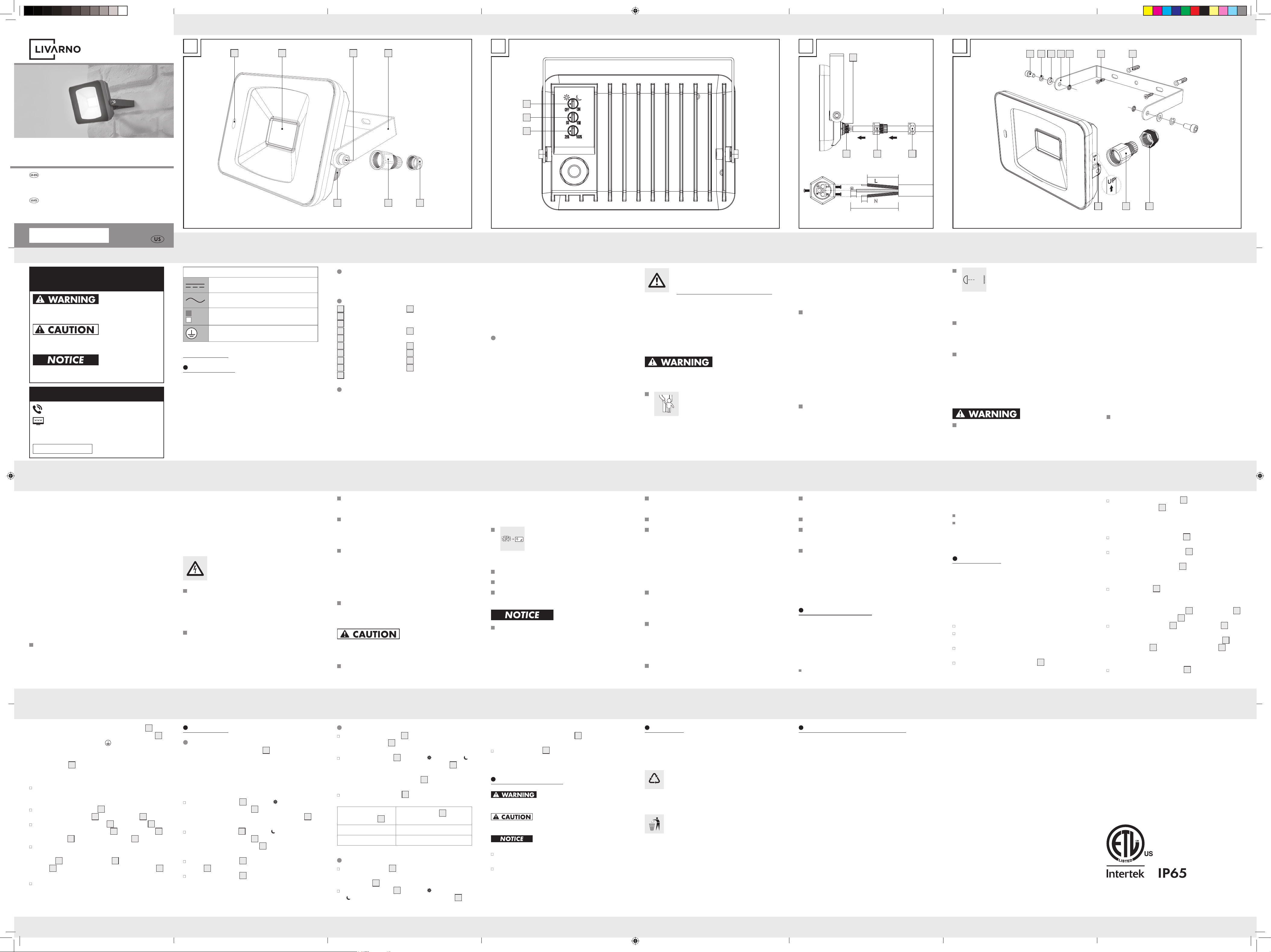
Parts description
1
Motion sensor
2
LED spotlight
3
Locking screw
4
Bracket
5
Cable gland
6
Terminal cover
7
Connection terminal
8
Mode knob
9
Time knob
10
Sensitivity knob
11
Screws
(D 0.16 in x 1.18 in
(4 mm x 30 mm))
12
Wall plug
(D 0.24 in (6 mm))
13
Tooth lock washer
14
Flat washer
15
Spring washer
16
Gasket
Technical data
Operating voltage: 120 V∼ 60 Hz
Total power consumption: 22 W
Motion sensor: Range: max. 314.96 in (8 m)
(adjustable),
Detection angle: 160 ° horizontal
Protection class: I
Degrees of protection: IP65 (dust-tight/water jets
protected)
IAN 553487_2601
LED SPOTLIGHT/
REFLECTOR LED PARA EXTERIORES
LED SPOTLIGHT
Assembly, operating and safety instructions
REFLECTOR LED PARA EXTERIORES
Manual de montaje, uso e indicaciones de seguridad
A
1 2 43
567
B
8
9
10
0.59 in - 0.78 in
(15 mm - 20 mm)
1.38 in - 1.77 in
(35 mm - 45 mm)
0.28 in (7 mm)
0.28 in (7 mm)
C
16
567
D
3 15 14 4 13 11 12
567
1
V2.0
DESCRIPTION OF SIGNAL
WORDS
WARNING indicates a hazardous situation that, if not
avoided, could result in death or serious injury.
CAUTION indicates a hazardous situation that, if not
avoided, could result in minor or moderate injury.
NOTICE indicates information considered important, but not
hazard related (e.g. messages related to property damage).
CUSTOMER SERVICE
Call customer service at 1 (844) 543-5872
Visit the Website Customer Service Platform at
www.lidl.com/contact-us
Visit a LIDL store for further assistance.
IAN 553487_2601
Please have your IAN
number ready.
553487_2601_V2.0_liv_LED-Aussenstrahler_A_US.indd 1 01.06.26 11:32
US-ES
US-ES
US-ES
US-ES
US-ES
US-ES
US-ES
US-ES
US-ES
US-ES
US-ES
US-ES
US-ES
US-ES
US-ES
US-ES
US-ES
US-ES
US-ES
US-ES
US-ES
US-ES
US-ES
US-ES
US-ES
US-ES
US-ES
¿Qué debe hacer usted para mantener la
garantía vigente?
· Guardar el recibo original.
· Seguir todas las instrucciones para el uso del producto.
· No realizar ninguna reparación ni alteración al producto.
¿De qué manera influyen las leyes estatales
con esta garantía?
La presente garantía le otorga derechos legales específi-
cos, y pudiera usted contar con otros derechos los cuales
varían de un estado a otro. Todas las garantías implícitas
se encuentran limitadas a la duración y términos de la pre-
sente garantía. Algunos estados no permiten limitaciones
al período de tiempo y términos de la garantía implícita,
por lo que dichas limitaciones pudieran no aplicarse en su
caso.
Período de cobertura y resolución de la garantía
La garantía es válida por 3 años a partir de la fecha de
compra. La empresa, según lo estime conveniente, devol-
verá el dinero o repondrá el producto.
La empresa no:
· Dará inicio a un nuevo período de garantía al hacerse el
cambio del producto.
· Reparará el producto.
¿Cómo se tramita la garantía?
Recomendamos que primero usted:
· Llame al Servicio de atención al cliente al
1 (844) 543-5872
· Visite el Portal de atención al cliente en
www.lidl.com/contact-us
· Visite una de nuestras tiendas LIDL en caso de cualquier
inquietud.
A fin de acelerar el trámite de la garantía, tenga a bien
contar con lo siguiente:
· Recibo de venta original que incluya la fecha de compra.
· Producto y manual en su empaque original.
· Descripción del problema.
· Daños que no hayan sido causados por el desgaste pro-
pio del uso o por no seguir las instrucciones de seguridad
y mantención incluidas en el manual para el usuario.
Lo que no cubre esta garantía
La garantía no cubre daños causados por:
· El desgaste propio del uso del producto, incluidas las
partes frágiles (como interruptores, piezas de vidrio, etc.).
· Uso o transporte no indicado del producto.
·
Desatención a las instrucciones de seguridad y mantención.
· Accidentes o causas de fuerza mayor (e.g. relámpagos,
incendio, inundación, etc.).
· Manipulación mal intencionada del producto (retirar la
cubierta, tornillos, etc.).
La presente gar
antía tampoco cubre daños indirectos o
emergentes. Sin embargo algunos estados no permiten la
exclusión o limitación de daños indirectos o emergentes, por
lo que dicha exclusión o limitación pudiera no aplicarse
en su caso.
b
a
Observe las señales del material de empaque
para la separación de residuos, los cuales están
señalados con abreviaturas (a) y números (b)
que significan lo siguiente: 1–7: plásticos/
20–22: papel y tablero de fibra/80–98:
materiales mixtos.
Contacte a las autoridades locales correspon-
dientes para la eliminación de desechos para
mayor información sobre cómo desechar su
producto desgastado.
Para ayudar a proteger el medio ambiente, elimine el pro-
ducto adecuadamente al final de su vida útil, no lo tire en
la basura normal. Puede obtener información de sus auto-
ridades locales sobre los puntos de recolección y horarios
de atención.
Garantía limitada de 3 años
Lo que cubre la presente garantía
La garantía incluye:
·
Daños, quebraduras o incapacidad para funcionar debido
a defectos.
de la iluminación se puede ajustar en un periodo de
5 segundos (= 5 S) a 10 minutos (= 10 M).
Limpieza y cuidado
Retire el fusible en la caja de
fusibles o apague el disyuntor en el panel del disyuntor
antes de limpiar.
El producto se calienta cuando está
encendido. Deje que el producto se enfríe completamente
antes de limpiarlo.
Nunca sumerja el producto en agua u
otros líquidos. Esto podría dañar el producto.
Limpie el producto con un trapo ligeramente húmedo
y sin pelusa y un detergente suave.
Después de la limpieza, vuelva a colocar el fusible o
encienda el disyuntor.
Eliminación
Deshágase del empaque mediante sus instalaciones de re-
ciclaje locales y de acuerdo con las regulaciones federales,
estatales y locales.
Nota: el producto confirma el cambio de modo con
un parpadeo breve del reflector LED
2
. El modo de
luz está ahora configurado.
Gire la perilla de sensibilidad
10
de 25 % a 100 %
para la sensibilidad del sensor.
Nivel de sensibilidad
(perilla de sensibilidad
10
)
El reflector LED
2
responde
a movimientos en un radio de
25 % hasta 39.37 in (1 m)
100 % hasta 314.96 in (8 m)
Perilla de tiempo
Utilice la perilla de tiempo
9
para ajustar la duración
de tiempo en que el producto se enciende después de
ser activado por el sensor de movimiento
1
.
Gire la perilla de modo
8
a la posición (modo
DAY)/
(modo NIGHT) para activar el sensor de mo-
vimiento
1
.
Nota: el producto confirma el cambio de modo con
un parpadeo breve del reflector LED
2
. El modo de
luz está ahora configurado.
Gire la perilla de tiempo
9
en sentido horario para
aumentar la duración de la iluminación. La duración
Gire la perilla de modo
8
a la posición para activar
el modo DAY (día). El sensor de movimiento
1
detecta
movimientos con luz de día, así como en la oscuridad.
El reflector LED
2
se enciende automáticamente tan
pronto como se detecta movimiento.
Gire la perilla de modo
8
a la posición para activar
el modo NIGHT (noche). El sensor de movimiento
1
detecta movimientos solo en la oscuridad. El reflector
LED
2
se enciende automáticamente tan pronto como
se detecta movimiento.
Gire el perillo de modo
8
a la posición ON. El reflector
LED
2
se enciende de forma permanente.
Gire la perilla de modo
8
a la posición OFF para
apagar el producto.
Perilla de sensibilidad
Use la perilla de sensibilidad
10
para ajustar la sensi-
bilidad del sensor de movimiento
1
. El ángulo de de-
tección aumenta o disminuye automáticamente con la
sensibilidad seleccionada.
Gire la perilla de modo
8
a la posición (modo
DAY)/
(modo NIGHT) para activar el sensor de
movimiento
1
.
Asegúrese de que la junta tórica
16
esté correctamente
instalada. Luego bloquee nuevamente la tapa terminal
6
y el pasamuros
5
.
Ahora coloque el reflector LED
2
al soporte
4
usando
los tornillos de fijación
3
, las arandelas de resorte
15
,
las arandelas planas
14
y las arandelas de seguridad
dentadas
13
(fig. D).
Ajuste el producto a la dirección deseada. Para este fin
es posible que necesite aflojar los tornillos de fijación
3
entre el soporte
4
y reflector LED
2
. Después del
ajuste, apriete los tornillos de fijación
3
en la articu-
lación para que quede asegurada.
Después de insertar el fusible o de encender la caja
de fusibles, su producto está listo para usarse.
Funcionamiento
Perilla de modo
Puede usar la perilla de modo
8
para
- encender el producto,
- seleccionar el tipo de iluminación,
- configurar con qué intensidad se debe activar el pro-
ducto,
- apagar el producto.
haya cables ni alambres en esta área de la pared.
Haga dos orificios (D 0.24 in (6 mm)) e inserte los ta-
quetes
12
. Atornille el soporte
4
con ayuda de los
tornillos
11
y compruebe que esté apretado.
Afloje el pasamuros
5
y la tapa terminal
6
, luego
pase el cable de conexión (no incluido), tipo SJTW
18AWG 0.824 mm², a través del pasamuros
5
y ala
tapa terminal
6
a la terminal de conexiones
7
. Para
conocer el largo ade
cuado para los cables de cone-
xión, consulte la figura C.
Abra la terminal de conexiones
7
usando un desar-
mador de cruz para aflojar los tornillos. Inserte el ca-
ble de conexión en los orificios de la terminal de los
conexiones
7
. Ponga atención a las marcas en la ter-
minal de conexiones
7
(L vivo, N neutro y para el
cable de puesta a tierra) (fig. C). No se debe superar
la longitud total del cable de alimentación de 8.20 ft
(2.50 m). Cierre la terminal de conexiones
7
apre-
tando los tornillos.
Nota: la temperatura mín. de los conductores de
alimentación es 194 °F (90 °C).
Asegúrese de que cada alambre del cable de conexión
esté completamente insertado en el extremo de los ori-
ficios de la terminal y compruebe que estén fijados de
forma segura.
Seleccione una pared sólida y no sujeta a vibraciones.
Mantenga una distancia mínima de 7.87 in (20 cm) a
otros objetos para garantizar una buena ventilación.
Monte el producto solo en una dirección. La etiqueta
”UP” (arriba) en el producto en relación con la flecha
debe apunta hacia arriba (fig. D).
Asegúrese de que el reflector LED
2
ilumine el área
deseada. Puede mover el producto en forma vertical
para ajustar el ángulo.
Asegúrese de que el sensor de movimiento
1
cubra el
área deseada. El sensor de movimiento
1
tiene un rango
máximo de cobertura de 8 m, con un ángulo de cober-
tura de 160 ° (dependiendo de la altura de montaje,
es ideal una altura de 70.9 in–98.4 in (1.8 m–2.5 m)).
Asegúrese de que el sensor de movimiento
1
no sea
iluminado por el alumbrado público en la noche. Esto
puede afectar su funcionamiento.
No ajuste el sensor de movimiento
1
hacia árboles,
arbustos o lugares donde los animales puedan ser de-
tectados fácilmente. No ajuste el sensor de movimiento
1
hacia calefactores, aires acondicionados, albercas
u otros objetos con temperaturas que cambian rápida-
mente.
Use el soporte
4
como plantilla para marcar los
orificios a taladrar en la pared. Asegúrese de que no
estar familiarizada con las propiedades del producto y la
normativa sobre conexiones.
Antes de instalarla, asegúrese de que el circuito al que
se conecta el producto no esté energizado. Coloque
nuevamente el fusible o encienda el disyuntor (posi-
ción 0) dentro de la caja de fusibles.
Use un comprobador de voltaje para verificar que no
haya carga.
El material de montaje incluido es adecuado para es-
tructuras normales de tabique y concreto sólido. Verifi-
que que el material de montaje sea adecuado para la
superficie donde va a instalar. De ser necesario, consulte
a un experto.
Instalación
Asegúrese de no perforar conductos eléctricos, de gas o
agua dentro de la pared. Utilice un taladro eléctrico para
taladrar los orificios en la pared de ladrillos. Siga siempre
las instrucciones de seguridad del taladro eléctrico en su
manual de instrucciones correspondiente. De lo contrario,
existe riesgo de muerte o lesiones por descarga eléctrica.
Al seleccionar el sitio de montaje, ponga atención a lo si-
guiente:
No use la luz si se ve dañada de al-
guna forma.
No mire a la fuente de luz en funcio-
namiento.
El producto no es atenuable.
El LED y el controlador del LED no
pueden ser reemplazado.
Si las fuentes de iluminación fallan al
final de su vida útil, el producto debe
ser reemplazado por completo.
GUARDE ESTAS
INSTRUCCIONES
Antes de la instalación
Nota: retire todos los materiales de empaque del producto.
Importante: la conexión eléctrica debe ser realizada
por un electricista calificado o una persona capacitada
para realizar instalaciones eléctricas. Esta persona deberá
El reflector solo es apto para usarse
con el control LED integrado.
Apto para sitios húmedos.
El producto sigue absorbiendo una
pequeña cantidad de energía incluso
si la lámpara está apagada y mientras
el producto esté conectado a la co-
rriente eléctrica. Para apagar el pro-
ducto completamente, retire el fusible
o apague el disyuntor en la caja de
fusibles.
No use este producto con atenuado-
res o interruptores electrónicos. No
está diseñado para estos fines.
Antes de la instalación, compruebe que
el material de montaje incluido sea
apto para el techo en el que desea
montar el producto.
=
¡RIESGO DE LESIONES!
Si se daña el vidrio de la
lámpara se debe reemplazar
antes de continuar utilizando el pro-
ducto.
¡RIESGO DE DESCARGA ELÉC-
TRICA!
¡RIESGO DE INCENDIO!
Solo se debe instalar a una distancia
superior a la de una brazada.
Tenga en cuenta que la garantía no
cubre daños derivados del uso inade-
cuado, no hacer caso de las instruccio-
nes
de uso ni los avisos de seguridad
o por un uso no autorizado.
Nunca abra ninguno de los componen-
tes
del equipo eléctrico ni inserte obje-
tos en ellos. Existe el riesgo de lesiones
mortales por descarga eléctrica.
Para la instalación, póngase en con-
tacto con un electricista calificado si
tiene dudas.
El incumpli-
miento de las siguientes adver-
tencias puede provocar lesiones
o daños materiales.
¡RIESGO DE QUEMADURAS!
Para evitar quemaduras, verifique que
el producto esté apagado y se enfríe
durante al menos 15 minutos antes
de tocarlo. El producto se puede ca-
lentar mucho.
Riesgo de descarga
eléctrica
Siempre verifique que el producto esté
intacto antes de conectarlo a la alimen-
tación. Nunca use el producto si detecta
algún daño.
Antes de instalar el producto, verifique
que el voltaje disponible corresponde
al voltaje requerido para utilizar el
producto (120 V∼ 60 Hz). De lo con-
trario, no instale el producto.
No utilice el producto si detecta cual-
quier tipo de daño.
En caso de daño, reparaciones u otros
problemas con el producto, consulte
a un electricista.
• Solicite ayuda a su proveedor o a
algún técnico experto de radio/te-
levisión.
Este producto cumple con el apartado
15 del reglamento FCC. La opera-
ción está sujeta a las siguientes dos
condiciones:
(1) Puede que este producto no cause
interferencia dañina, y
(2) este producto debe aceptar cual-
quier interferencia recibida, incluyendo
aquella que pueda causar una ope-
ración no deseada.
Sin embargo, no existe ninguna garan-
tía de que no se produzcan interferen-
cias en una instalación en particular. Si
este producto causa una interferencia
dañina a la recepción de radio o tele-
visión, la cual puede ser determinada
encendiendo y apagando el producto,
se alienta al usuario a intentar corregir
las interferencias siguiendo las siguien-
tes medidas:
• Oriente o localice de nuevo la an-
tena receptora.
• Aumente la separación entre el
producto y el receptor.
• Conecte el producto a una toma
de corriente en un circuito distinto
de aquel al que esté conectado el
receptor.
del cumplimiento podrían anular la
autorización del usuario para operar
el producto.
Nota: este producto ha sido probado
y cumple con los límites para un pro-
ducto digital clase B, de acuerdo con
el apartado 15 de las normas de la
FCC. Estos límites están diseñados
para brindar protección razonable
contra interferencias perjudiciales en
una instalación residencial.
Este producto genera, usa y puede
emitir energía de radiofrecuencia y en
caso de no ser instalado y utilizado
de acuerdo a las instr
ucciones puede
causar interferencias perjudiciales a
las radiocomunicaciones.
(1 m) alejado del artículo a ser ilumi-
nado. El calor excesivo puede provo-
car un incendio.
Consulte a un eléctrico calificado para
asegurarse de que el conductor del
ramal eléctrico esté instalado correc-
tamente.
Este producto se debe instalar de
acuerdo con el reglamento de instala-
ción correspondiente, por parte de una
persona familiarizada con la construc-
ción y la operación del producto y los
riesgo que implica.
Los cambios o modificaciones a este
producto que no sean expresamente
aprobados por la parte responsable
niños) con capacidades físicas, sen-
soriales o mentales reducidas o con
falta de experiencia y conocimiento,
a menos que sean supervisadas o ins-
truidas por una persona responsable
de su seguridad. Supervise siempre a
los niños para asegurarse de que no
jueguen con el producto.
¡PELIGRO DE ASFIXIA! Los niños
podrían tragar y ahogarse con las
piezas pequeñas incluidas (p. ej. tor-
nillos). Mantenga a los niños aleja-
dos del área de trabajo durante el
ensamblaje.
39.37 in
(1 m)
¡PELIGRO DE INCENDIO!
Instale el producto para que
esté al menos a 39.37 in
TACIÓN AL PASAR ESTE PRODUCTO
A TERCEROS.
El incumpli-
miento de las siguientes adver-
tencias puede provocar lesiones
graves o la muerte.
¡PELIGRO DE MUERTE Y
RIESGO DE ACCIDENTE
PARA BEBÉS Y NIÑOS!
Nunca deje a los niños solos y sin su-
pervisión con el material de empaque
.
El material de empaque puede provo-
car asfixia. Los niños suelen subesti-
mar los peligros. Mantenga siempre
este producto alejado de los niños.
Este producto no está diseñado para
ser usado por personas (incluyendo
Contenido
Inmediatamente después de desempacar, verifique que
las piezas estén completas y que el producto esté en
buen estado.
1 reflector LED para exterio-
res
2 taquetes
(D 0.24 in (6 mm))
2 tornillos
(D 0.16 in x 1.18 in
(4 mm x 30 mm))
1 tapa terminal
1 pasamuros
1 juego de instrucciones de
uso
INSTRUCCIONES
IMPORTANTES
DE SEGURIDAD
LEA TODAS LAS INSTRUCCIONES.
CONSERVE PARA FUTURAS REFEREN-
CIAS. INCLUYA TODA LA DOCUMEN-
12
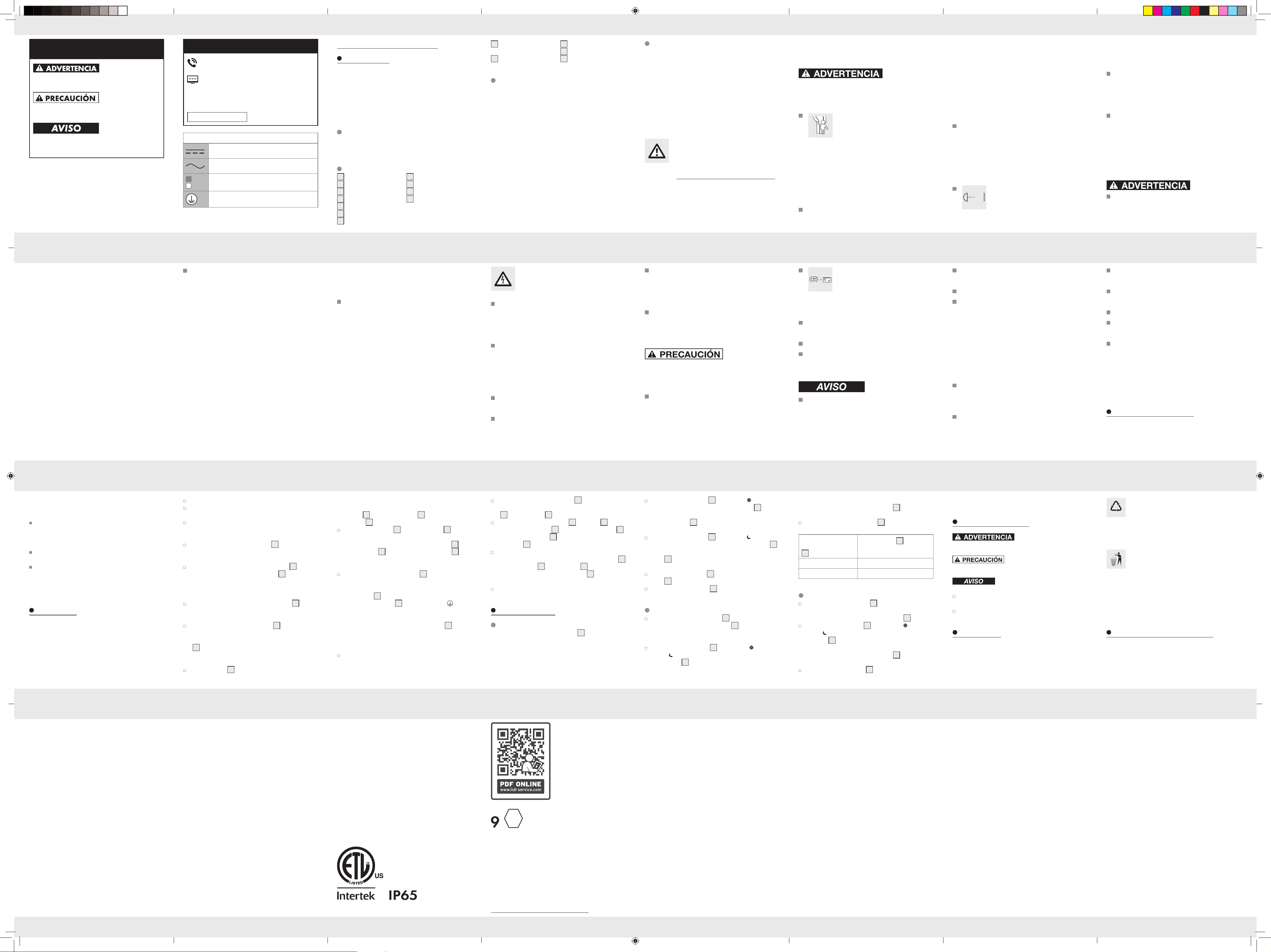
Taquete
(D 0.24 in (6 mm))
13
Arandela de seguridad
dentada
14
Arandela plana
15
Arandela de resorte
16
Junta tórica
Información técnica
Voltaje de operación: 120 V∼ 60 Hz
Consumo total de energía: 22 W
Sensor de movimiento: Rango: máx. 314.96 in (8 m)
(ajustable),
Ángulo de detección: 160 °
horizontal
Clase de protección: I
Grados de protección: IP65 (a prueba de polvo/pro-
tegido contra chorros de
agua)
Peso: 1.32 lb (600 g)
Dimensiones generales: 7.09 in x 4.92 in x 2.36 in
(18 cm x 12.5 cm x 6 cm)
Área de proyección: máx. 34.87 in
2
(225 cm
2
)
Altura de montaje: 70.9 in–98.4 in (1.8 m–2.5 m)
Banda de frecuencia: 5.740 GHz–5.835 GHz
Potencia máx. transmitida: 3 dBm
ID de la FCC: 2BWF3-FL180X125
Reflector LED para exteriores
Introducción
Las instrucciones de uso son parte del producto. Contienen
información importante respecto a la seguridad, el uso y la
eliminación. Antes de usar el producto, familiarícese con
toda la información de seguridad y las instrucciones de uso.
Utilice la unidad únicamente como se describe y para las
aplicaciones indicadas. Si traspasa el producto a alquien más,
por favor asegúrese de incluir toda la documentación con él.
Uso previsto
Este producto está diseñado para iluminar únicamente
áreas en exteriores. Este producto está diseñado sólo para
uso doméstico.
Descripción de las piezas
1
Sensor de movimiento
2
Reflector LED
3
Tornillo de fijación
4
Soporte
5
Pasamuros
6
Tapa terminal
7
Terminal de conexiones
8
Perilla de modo
9
Perilla de tiempo
10
Perilla de sensibilidad
11
Tornillos
(D 0.16 in x 1.18 in
(4 mm x 30 mm))
Lista de pictogramas utilizados
Corriente directa/voltaje
Corriente alterna/voltaje
Información de seguridad
Instrucciones de uso
Tierra de protección
DESCRIPCIÓN DE LAS PALABRAS
DE ADVERTENCIA
ADVERTENCIA indica una situación peligrosa, que puede
provocar la muerte o lesiones graves si no se evita.
PRECAUCIÓN indica una situación peligrosa, que puede
provocar lesiones leves o moderadas si no se evita.
AVISO indica información que se considera importante,
pero que no implica un peligro (p. ej. mensajes relacio-
nados con daños materiales).
SERVICIO AL CLIENTE
Llame al Servicio de atención al cliente al
1 (844) 543-5872
Visite el Portal de atención al cliente en
www.lidl.com/contact-us
Visite una de nuestras tiendas LIDL en caso de cualquier
inquietud.
IAN 553487_2601
Por favor tenga su número
IAN a la mano.
Distributed by/Distribuido por:
LIDL US, LLC, Arlington, VA 22202
Model No./Modelo Núm.:
HG14764A-US
Version/Versión: 08/2026
Made in/Hecho en: Ningbo, China
Last Information Update · Estado de las informaciones:
05/2026 · Ident.-No.: HG14764A-US052026-9
553487_2601_V2.0_liv_LED-Aussenstrahler_A_US.indd 2 01.06.26 11:32