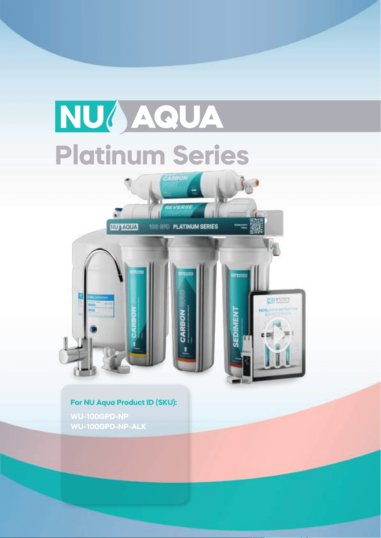
Platinum Series
Installation Manual
For NU Aqua Product ID (SKU):
WU-100GPD-NP
WU-100GPD-NP-ALK
WU-100GPD-NP-UV
WU-100GPD-NP-UV-ALk
WU-100GPD-WP
WU-100GPD-WP-ALK
WU-100GPD-WP-UV
WU-100GPD-WP-UV-ALk
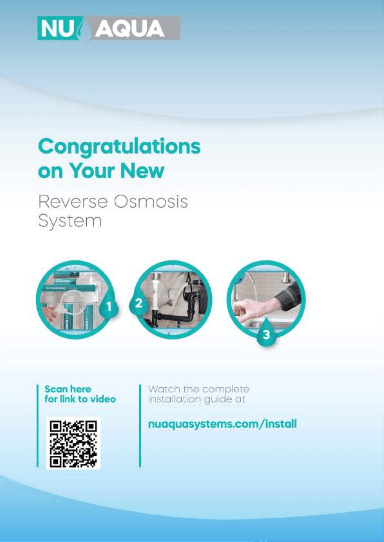
Congratulations
on Your New
Reverse Osmosis
System
Scan here
for link to video
Watch the complete
installation guide at
nuaquasystems.com/install
1
2
3

Table of contents
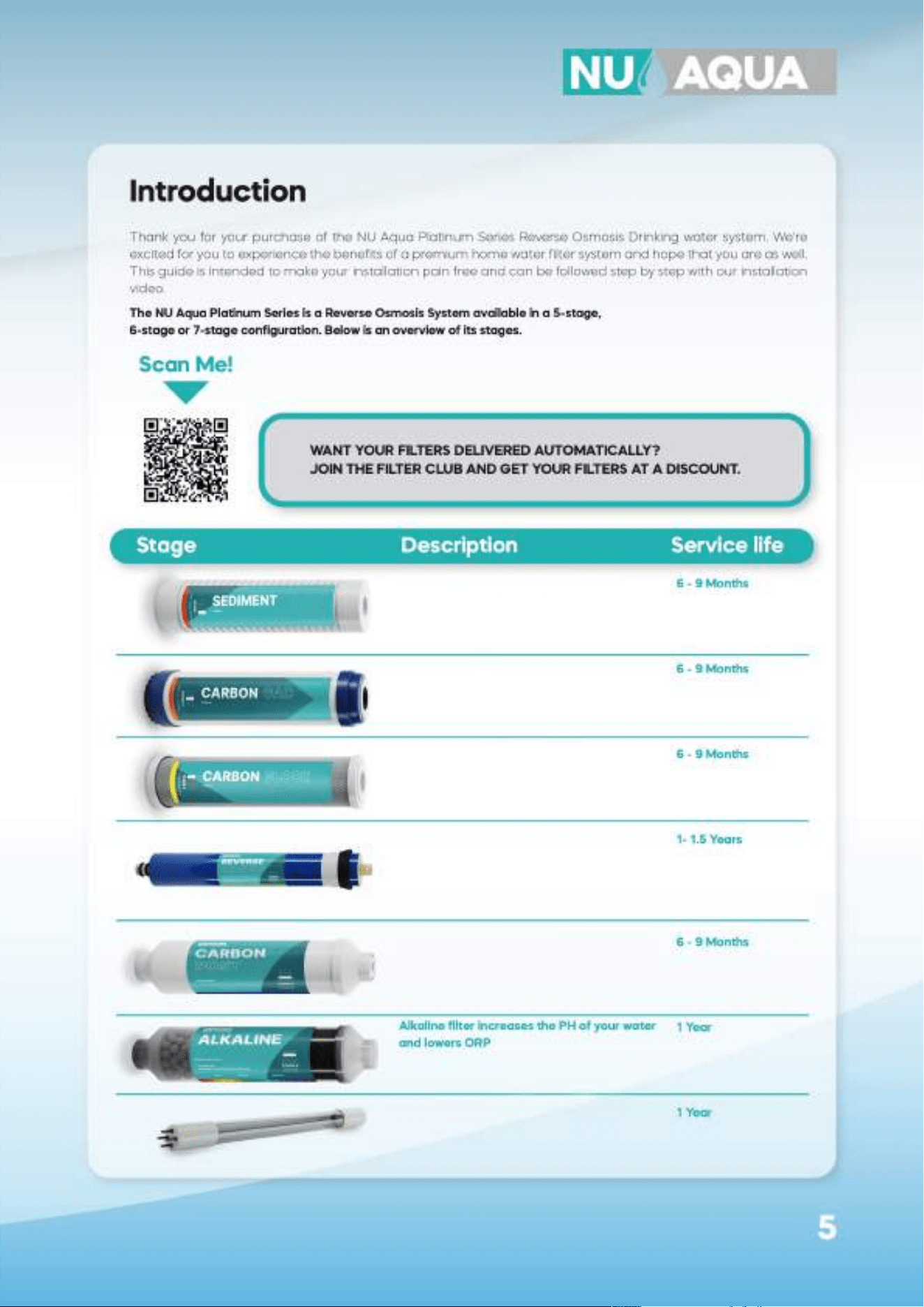
Introduction
Conditions Page 4
Introduction Page 5
Preparation
Inspection Page 6
Recommended tools Page 6
System requirements Page 6
Installation components Page 6
Quick connect guide Page 7
Tube cutting guide Page 7
Installation
Feed water adapter Page 8
Leak stop valve Page 9
Drain saddle Page 10
Faucet installation Page 11
Tank installation Page 12
Filter housing install Page 13
Optional alkaline filter install Page 14
Optional uv filter install Page 14
System connections
5 stage Page 15
6 stage alkaline Page 16
6 stage uv Page 17
7 stage Page 18
5 stage with pump Page 19
6 stage alkaline with pump Page 20
6 stage uv with pump Page 21
7 stage with pump Page 22
Optional refrigerator kit Page 23
System use and care
System startup Page 24
Filter changes Page 25
System sanitizing Page 26
Vacation mode Page 26
Trouble shooting Page 27
System diagrams Page 28-35
Service data sheet Page 36-37
Warranty Page 38-39
4
INCOMING WATER
Incoming water pressure must be between 45 PSI and 80 PSI for NU Aqua no pump reverse osmosis systems.
For incoming water pressure below 45 PSI and as low as 15 PSI, we recommend our reverse osmosis systems
with booster pumps. Test your water pressure occasionally to make sure the system is performing. If your water
is microbiologically unsafe or of unknown quality do not use this system without adequate disinfection before
or after the system. Extremely hot or cold incoming water will damage the system and cannot be used. Do not
install where water hammer conditions exist, you should install a water hammer arrestor
LEAKS
The included Leak Stop Valve must be installed. Inspect all connections after the installation to make sure no
leaks occur, wait until after the system is pressurized (turned on) to inspect again. Check the system occasional-
ly after installation or maintenance to make sure no leaks have developed. Install the system in a location with
adequate drainage.
GENERAL
This RO System unit is for climate controlled indoor use only. Exposure to overly high or low temperature ranges
will damage the unit. Follow all of your state and local laws and codes regarding plumbing even if they dier
from what is stated in this manual. If your state law requires it or you prefer to we recommend using a professio-
nal licensed installer or plumber who meets the requirements of this system. All O-Rings, fittings, tubing, filter
canisters, and teflon tape wear out after a certain period of time. The lifetime of your components are subject
to change with the quality of the water supplied. Do not handle an unwrapped filter directly with your bare
hands as this can cause early filter failure. Use appropriate eye and face protection when performing any
drilling.
MAINTENANCE
The owner/user is obligated to properly maintain the RO System when necessary, at least every 1 year. This
includes the following:
-Always use NU Aqua Systems replacement filters in accordance with the filter change schedule.
-Sanitize your system as often as needed (how often changes with the quality of incoming water).
At least every 3 years:
-Replace the tubing, fittings, and filter cartridges
-Replace leak stop valve.
-Replace the teflon tape on all threaded connections and fittings.
-Replace the O-rings on the filter housings, membrane housing, fittings and filter cartridges.
-Replace any connectors and filter housings with proper replacement parts.
At least every 5 years:
-Replace the faucet
-Replace water storage tank
LIMIT OF LIABILITY
In all circumstances, NU Aqua System’s maximum liability is limited to the purchase price of the product(s) sold.
NU Aqua Systems is not responsible or financially liable for any water damage, property damage, or personal
injury, direct or indirect, that may occur from normal or correct use of the products we sell, catastrophic failure
of the products we sell, failure to properly connect the units to water supply lines, and/or failure to understand
and observe the proper water pressure ratings and requirements for these units. Use, install and monitor all of
our products solely at your own risk. Always check all connections for leaks periodically. NU Aqua Systems is not
responsible for any leaks or water damage. In case some states do not allow the exclusion or limitation of
incidental or consequential damages, you may choose to return the system. If you choose to keep it, you insist
this exclusion still applies to you.
Conditions
READ THIS FIRST
-Please pay attention to the following installation and safety recommendations:
-Read the installation manual before installing this system.
5
Thank you for your purchase of the NU Aqua Platinum Series Reverse Osmosis Drinking water system. We're
excited for you to experience the benefits of a premium home water filter system and hope that you are as well.
This guide is intended to make your installation pain free and can be followed step by step with our installation
video.
The NU Aqua Platinum Series is a Reverse Osmosis System available in a 5-stage,
6-stage or 7-stage configuration. Below is an overview of its stages.
Introduction
Spun polypropylene sediment filter
removes dirt, rust and larger particles
Mesh coconut shell granular activated
carbon cartridge for removal of chlorine
and organic chemicals
Coconut shell carbon block for removing
volatile organic carbon compounds,
insecticides/pesticides and chemicals
For removing the following contaminants
in your water: Arsenic, Barium, Cadmium,
Chromium, Copper, Turbidity, Fluoride,
Lead, Radium, Selenium and TDS
Coconut shell post carbon filter for chlorine,
taste and odor reduction
Alkaline filter increases the PH of your water
and lowers ORP
UV-C light treatment — supplemental
ultraviolet treatment stage
WANT YOUR FILTERS DELIVERED AUTOMATICALLY?
JOIN THE FILTER CLUB AND GET YOUR FILTERS AT A DISCOUNT.
Scan Me!
Stage Description Service life
6 - 9 Months
6 - 9 Months
6 - 9 Months
1- 1.5 Years
6 - 9 Months
1 Year
1 Year
UV-C light treatment — supplemental
ultraviolet treatment stage
Filters arsenic, barium, cadmium,
chromium, copper, turbidity, sluoride,
lead, radium, selenium and TDS.
Coconut shell post carbon filters chlorine,
taste, and odor.
Coconut shell carbon block filters
volatile organic carbon compounds,
and chemicals.
Granular carbon block cartridge filters
chlorine, and organic chemicals.
Spun polypropylene sediment filters
dirt, rust, and larger particles.
6
After unpacking your new RO system and all the components, we recommend that you thoroughly inspect all
fittings and tubing to ensure nothing has come loose during shipping. If any part appears cracked or broken
from shipping, do not proceed with installation and contact us directly.
Email: support@nuaquasystems.com
Phone: 1(888) 621-0460
Inspection
Drill with a 1/4"
and 1/2" drill bit
Open ended
wrench
Phillips
screwdriver
Razor blade 14 mm
wrench
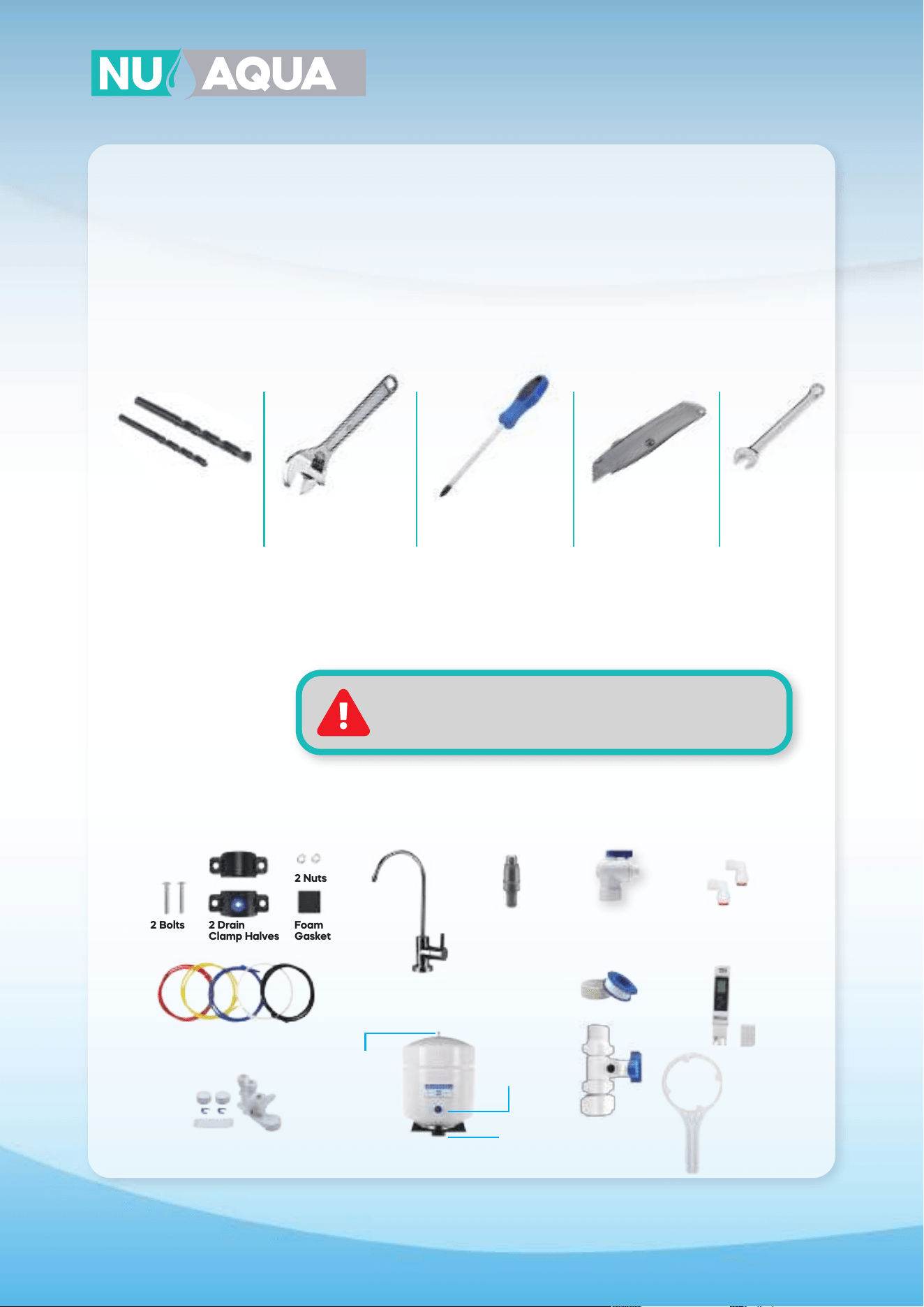
Recommended Tools
System Requirements
System Operating Pressure: 45 - 80 PSI (No Pump Systems)
System Operating Pressure: 15 - 45 PSI (With Pump Systems)
Incoming Water Temperature: 40° - 100°F (5°-38°C)
A Water Pressure Must Not Exceed 80PSI
Temperature must not exceed 100°F or go below 40°F
System is for indoor use only
Installation components
Drain saddle
RO Faucet
Tank Ball Valve
Filter Protection
Valve
Teflon Tape
Feed Water
Adapter
Elbows
(no pump systems)
Filter Housing
Wrench
TDS Meter
Air
Valve
Tank is
pressurized
at 7-10 PSI
(on empty)
Tank
Stand
2 Drain
Clamp Halves
Color coded 1/4” Tubing
Leak stop valve
2 Bolts Foam
Gasket
2 Nuts
7
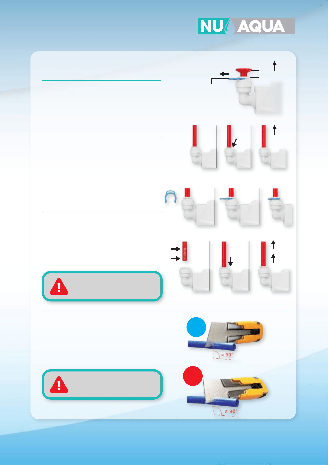
Tubing/Fittings/
Plug Removal
If there is a retaining clip on the collet of the fitting
it must be removed first. Push and hold the collet
down to unlock the tubing and gently pull the
tube/fitting/plug to remove it.
Quick Connect Guide
Install or Remove
Retaining Clips
To lock a tube in it’s fitting make sure that it is fully
inserted. Slide the retaining clip between the collet
and fitting. Before tubing can be removed from a
fitting you must remove this clip first. To remove the
retaining clip simply pull the clip away from the
fitting until it slide completely out.
Insert Tubing
Push the tubing straight and level into the fitting.
When inserting the tubing make sure you push until
it stops to ensure the lock is activated. The tubing
will travel 5/8” into the fitting. Gently pull on the
tubing to check that the lock is activated.
How to Cut Tubing
When cutting the supplied tubing its important to
use a sharp razor blade. Place the tubing on a flat
surface and cut straight through the tubing. All cuts
to your tubing must be perfectly straight to ensure
the best connections.
NOTE:
Always check each connection
to make sure its secure
NOTE:
Improperly cut tubing may cause
a leak
Plug
Collet
Locking
Clip
Pull Up
Hold
Down
Unlocked Locked
5/8”
5/8”
OK
X
8
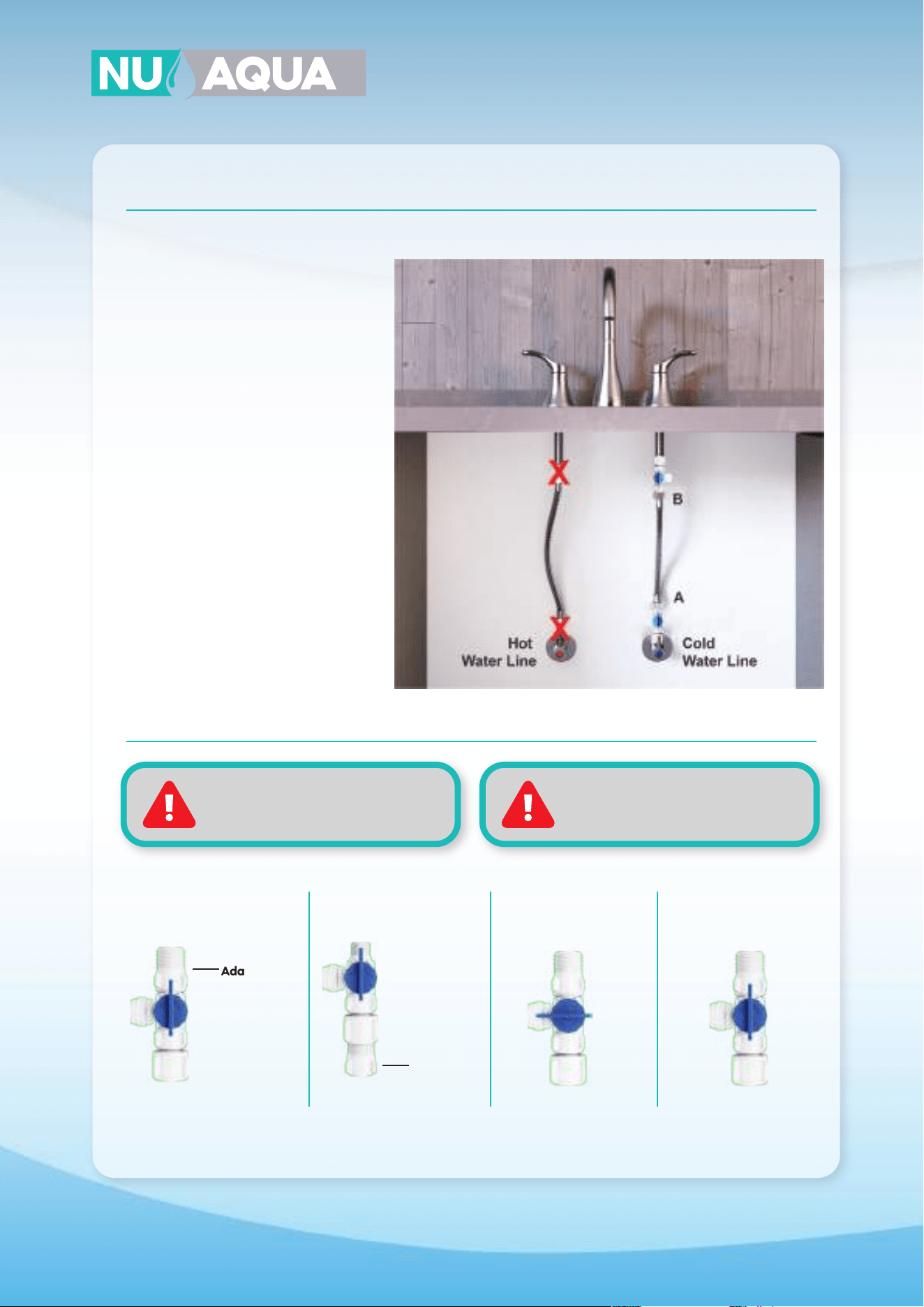
Installation
Feed Water Adapter
1. Locate and turn o the cold water
valve under your sink. Next turn on the
cold water faucet to drain any remai-
ning water in the line
2. Place a towel below your cold water
valve to catch any remaining water in
the line. Loosen the nut on the water
line where it is attached to the valve.
Feed water adapter can be installed in
either location A or B as illustrated in
the diagram”
3. Wrap the threads of the water valve
and feed water adapter 8-10 times with
teflon tape. Using a adjustable wrench
secure the feed water adapter onto the
cold water valve and the water line to
the feed water adapter.
4. Turn the feed water valve to the o
position for the remainder of the instal-
lation process.
5. Insert one end of your red tubing into
the quick connect fitting on your feed
water adapter. Secure in place with a
retaining clip.
WARNINGS:
Only connect to cold water line.
Hot water will damage your system.
WARNINGS:
Turn the hot water valve o when
installing on a single handed faucet.
1/2” Connection 3/8” Connection Open Closed
Adapter
Adapter
9
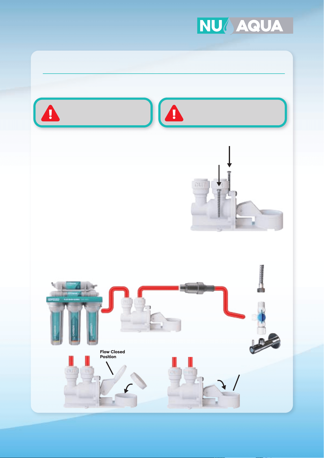
Installation
Filter Protection Valve & Leak Stop Valve Installation
WARNING:
failure to install Leak Stop Valve and
Pressure Regulator will void Warranty
NOTE:
it may be best to insert the cartridge after
the initial startup is complete
Flow Closed
Position
Flow Open
Position
Red Tube Red Tube
1. Locate the red tubing coming from the feedwater adapter
and make a cut approximately 6” away from the feedwater
adapter. Connect the end of the filter protection valve with
the longer barrel to the tubing coming from the feed water
adapter and connect the extra tubing to the other end of
the filter protection valve.
2. Locate the lowest point within your cabinet or installation
location. Using the included screws, secure your leak stop
valve in this location
3. Locate the red tubing coming from the filter protection
valve and cut it near the location of the leak stopper.
Connect the end of the red tubing coming from the feed
water adapter to the quick connect on the leak stop valve
labeled “in”.
4. Take o the plastic wrap o the leak cartridge and place it
inside the leak stop valve as shown.
5. Turn the leak stop valve switch down to put it in the on
position.
10
Installation
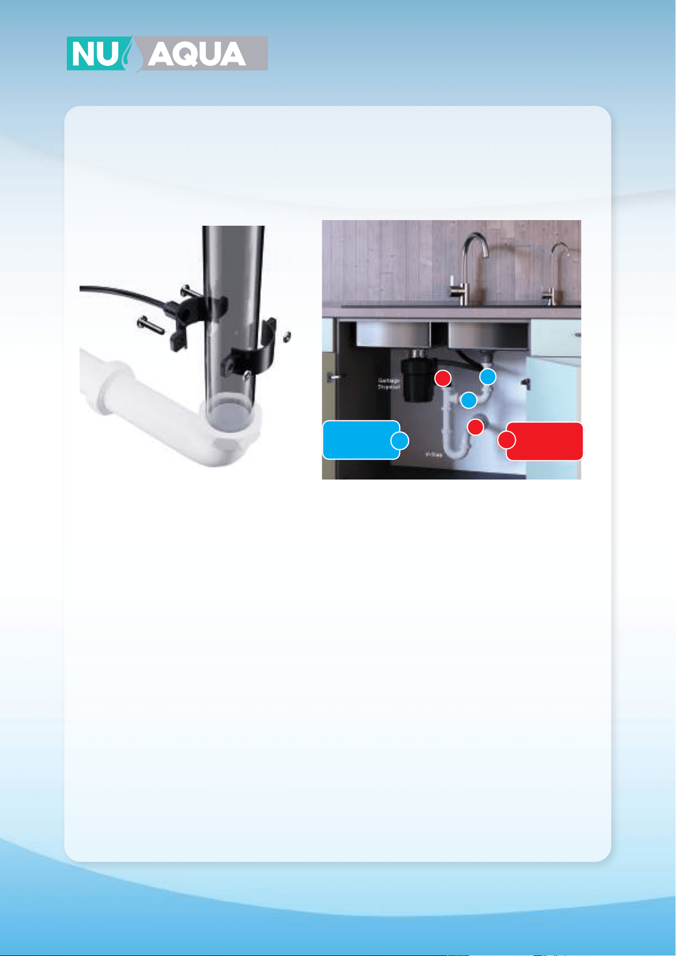
Drain Saddle
1. Locate a section on your drain plumbing using the
image above and mark the location with a pen. If the
drain saddle is to be installed on a horizontal section
you must position the hole on top of the pipe.
2. Use a drill with a 1/4” drill bit on the section you
marked. Be careful to drill only through one side of
the pipe.
3. Remove the center of the foam pad included with
the drain saddle. Peel o the adhesive tape on the
back side and attach it to the drain saddle half with
the quick connect fitting. Make sure the center hole
aligns with the hole in the drain saddle.
4. Press the two nuts into the back of the drain
saddle by hand.
5. Slide a small screwdriver through the quick
connect fitting on the drain saddle half and through
the hole drilled in your drain pipe. This will keep the
holes aligned during the installation.
6. While holding the drain saddle in place secure the
back half using the two supplied screws and a screw-
driver. Tighten both screws till the drain saddle is
secure. You may remove the screwdriver holding the
drain saddle in place.
7. Locate your black tubing and insert one end into
the quick connect fitting on your drain saddle.
OK
OK
X
X
OK
Mount Drain
Saddle at either
location
WARNING!
Never mount
there!
X
11
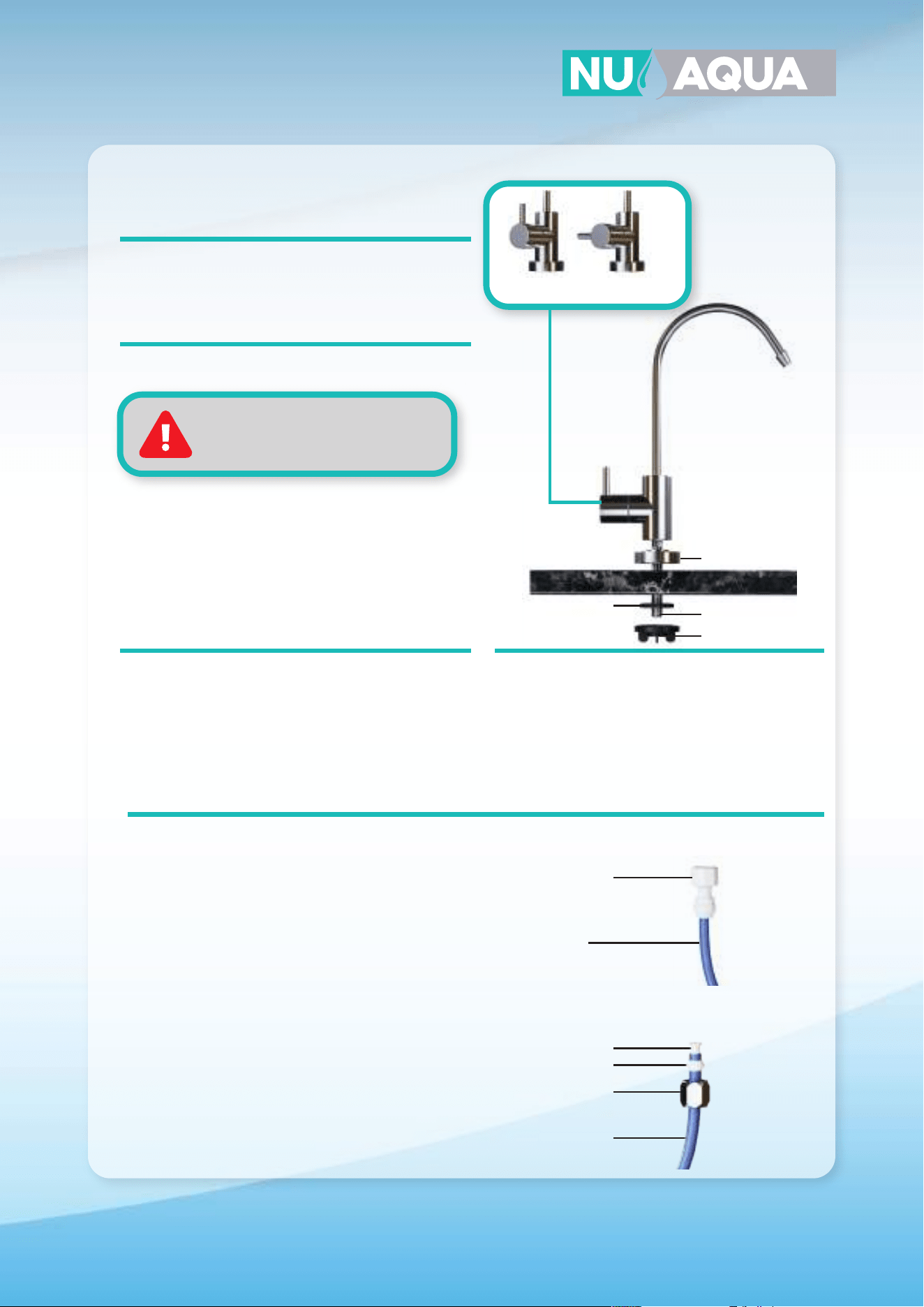
Installation
Faucet Installation
Drilling
If your sink has a existing hole this can be used for
your faucet. If you have to drill a new hole follow the
steps below.
1. Locate the section on your countertop to install
your faucet. Using plumbers clay form a ring around
the section you will be drilling. This will be used to
retain water for the drilling process.
2. Fill the ring with water. Using a diamond tip hole
saw drill bit slowly begin drilling. Apply light, and even
pressure and let the drill do the work.
1. Locate the section on your countertop to install
your faucet and drill a 1/4” pilot hole. Once comple-
tely drilled through switch to a 1/2” drill bit and re-drill
the same hole.
Granite / Marble / Quartz sinks
Stainless Sink
Keep the drill bit and hole wet
during the drilling process
1. Slide the base plate on the threaded faucet
stem. Insert the faucet into the hole in your coun-
tertop.
2. Under your sink slide the rubber washer on the
faucet stem. Secure the faucet in place by hand
with the wing nut.
Installation
TYPE A
1. Connect the blue tubing to the quick connect
fitting on your faucet adapter.
2. Screw the faucet adapter onto the threaded
faucet stem.
TYPE B
1. Slide the compression nut with the open end facing
upwards down your blue tubing. Follow the nut with
your sleeve.
2. Slide the insert into the opening of your tubing
firmly.
3. Insert your tubing into the faucet stem and tighten
the compression nut to secure it in place. Do not over
tighten.
Tubing Connection
TYPE B
TYPE A
OpenClosed
Open and Closed Position
Base Plate
Threaded Faucet
Stem
Rubber Washer
Faucet Adapter
Wing nut
Insert
Sleeve
Compression Nut
1/4” Tube
1/4” Tube
12
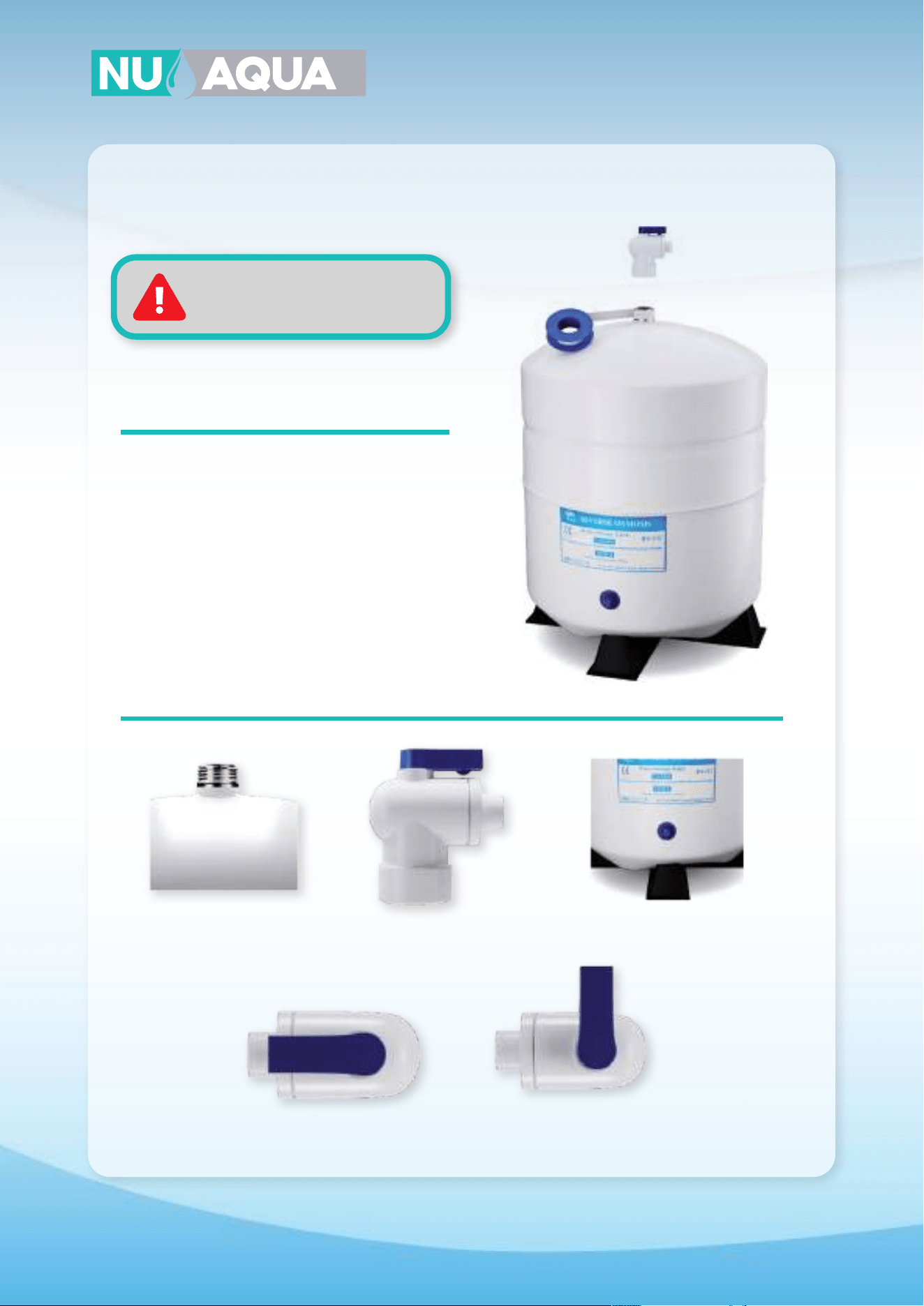
Installation
Tank Ball Valve
1. Apply 8-10 clockwise wraps of teflon tape to the
threads on the top of your storage tank.
2. Install your tank ball valve on the tank threads
and tighten by hand.
3. Unscrew the cap from the tank ball valve and
slide it down the yellow tubing.
4. Slide the yellow tubing into the tank ball valve
until it stops. Slide the cap up the yellow tubing and
tighten on to the ball valve by hand.
Do not release pressure
from storage tank unless needed.
NOTE: Tanks come pressurized between 7-10psi
when empty.
Tank Thread Tank Valve Tank Stand
Open
Closed
13
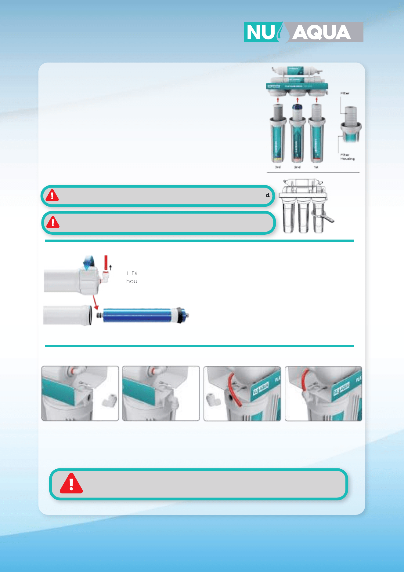
1. Remove the plastic wrapper from each filter and reinsert them back into
their housing. When inserting the stage 2 carbon GAC filter make sure the
white washer is facing up.
2. While keeping the filters standing vertically in the housing, attach them to
the system by threading it onto the cap. Refer to diagram for each filters
placement.
3. With all the filter housings installed, use the filter housing wrench to tighten
them fully into place.
Installation
Filter Housing Install
Membrane Installation
Elbow Installation (no pump systems only)
3. Reinstall the housing cap by hand then tighten with the housing wrench to ensure a proper seal.
2. Lubricate the double o-rings with water and insert
membrane. Make sure membrane is fully inserted.
1. Disconnect the red tubing connected to the membrane housing cap. Use the
housing wrench to loosen and remove the cap.
1. Screw in your elbow into the inlet side of the
system. DO NOT OVERTIGHTEN OR USE TOOLS
TO TIGHTEN.
2. Screw in your elbow into the outlet side of the system.
DO NOT OVERTIGHTEN OR USE TOOLS TO TIGHTEN.
Once installed connect the loose red tubing to
this fitting.
Food grade lubricant is used on the o-rings. Do not clean this o, it’s used to
prevent over tightening.
DO NOT OVERTIGHTEN HOUSING. Labels may not face forward when tightened.
When installing elbow fittings do not use tools to tighten.
Teflon is preapplied to elbows for you convenience. Do not remove. However, if necessary,
apply 8-10 wraps of teflon tape to the elbow fitting threads.
14
Installation
6 Stage System Assembly
For Product ID (SKU):
WU-100GPD-NP-ALK, WU-100GPD-WP-ALK
WARNING: Do not forget to install
o-ring on quartz tube
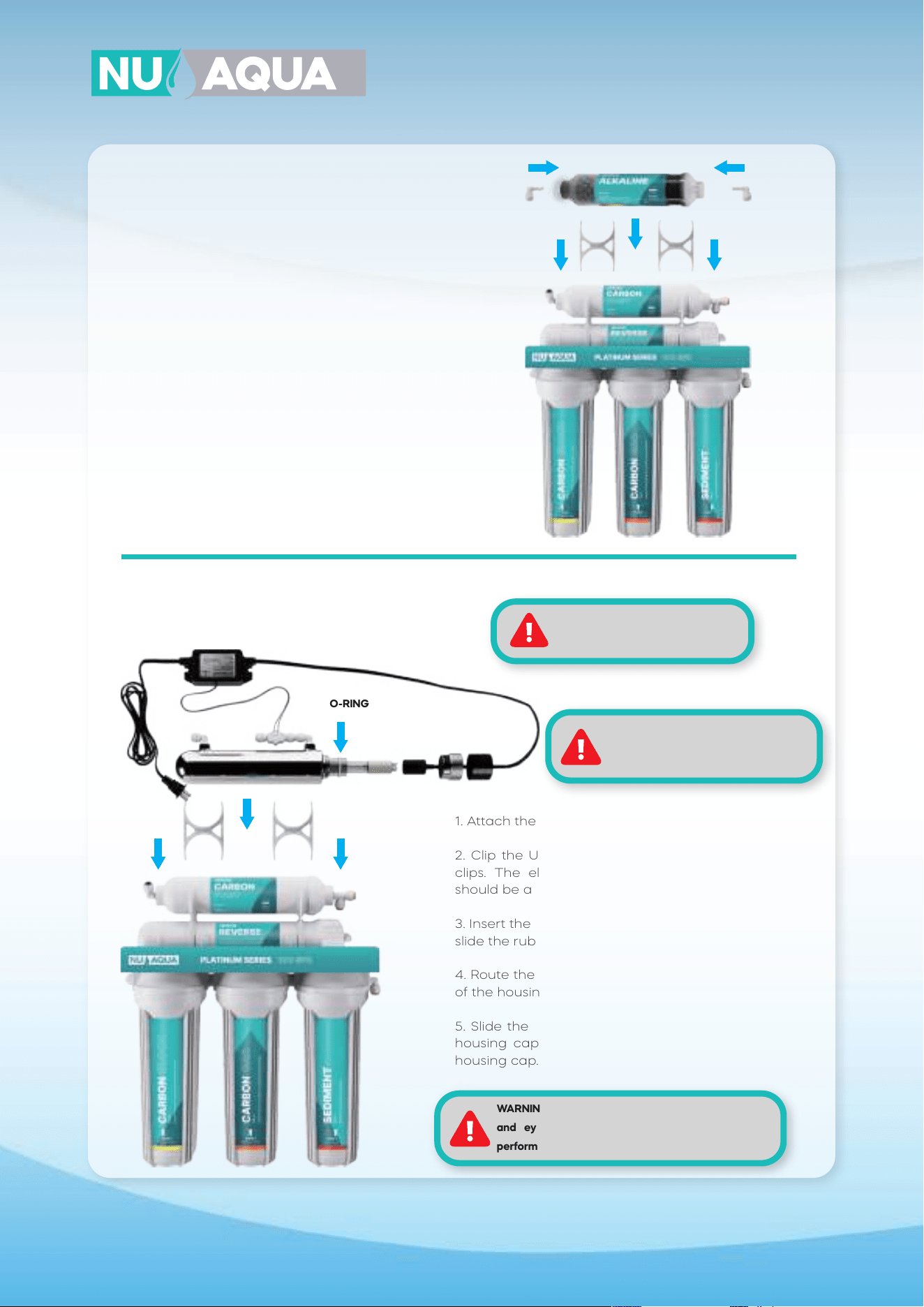
1. Insert one quick connect elbow into the quick
connect fitting on each end of the alkaline filter.
2. Attach the filter housing clips to the post filter.
3.. Clip the alkaline filter into the two housing clips.
1. Attach the filter housing clips to the post filter.
2. Clip the UV filter housing into the two housing
clips. The elbow fitting without the flow sensor
should be above the exit of the post filter.
3. Insert the quartz tube into the filter housing and
slide the rubber o-ring onto the quartz tube.
4. Route the UV ballast bulb plug through the cap
of the housing and connect it to the bulb.
5. Slide the bulb into the quartz tube, tighten the
housing cap, and slide the rubber cap over the
housing cap.
UV Filter Installation
For Product ID (SKU):
WU-100GPD-NP-UV, WU-100GPD-WP-UV
Alkaline Filter Installation
O-RING
WARNING: Wear gloves when
handling UV bulb. Oil from your hands
can lower the lifespan of the bulb.
WARNING: Do not look directly at UV light. Avoid skin
and eye exposure. Always unplug power before
performing any maintenance.
15
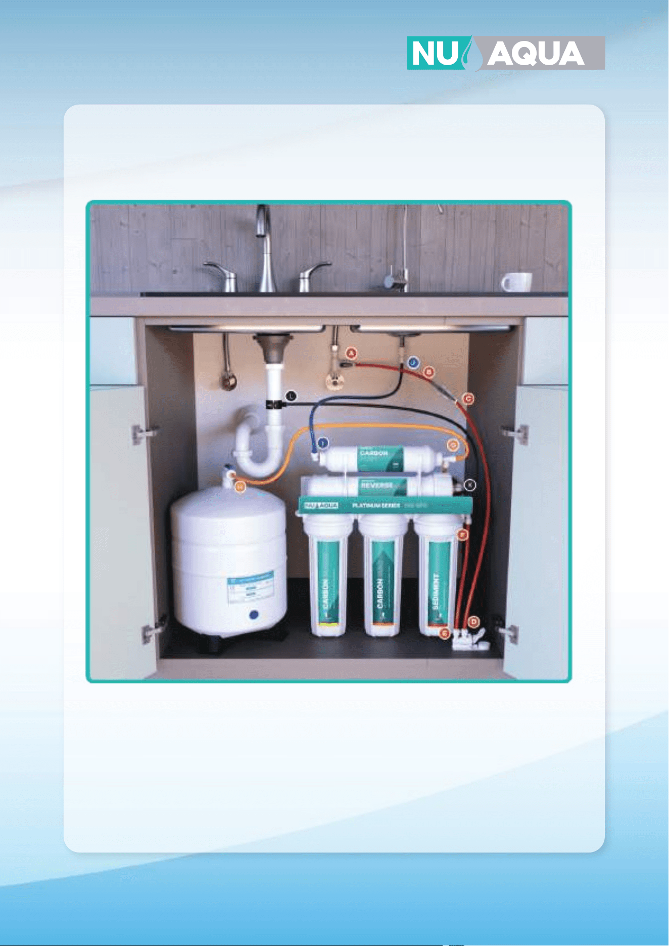
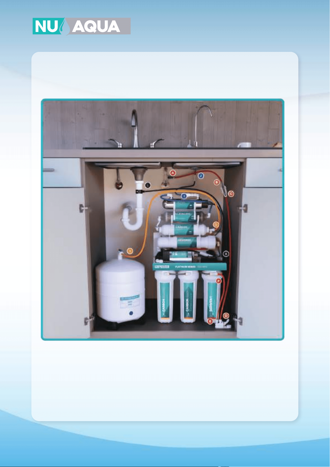
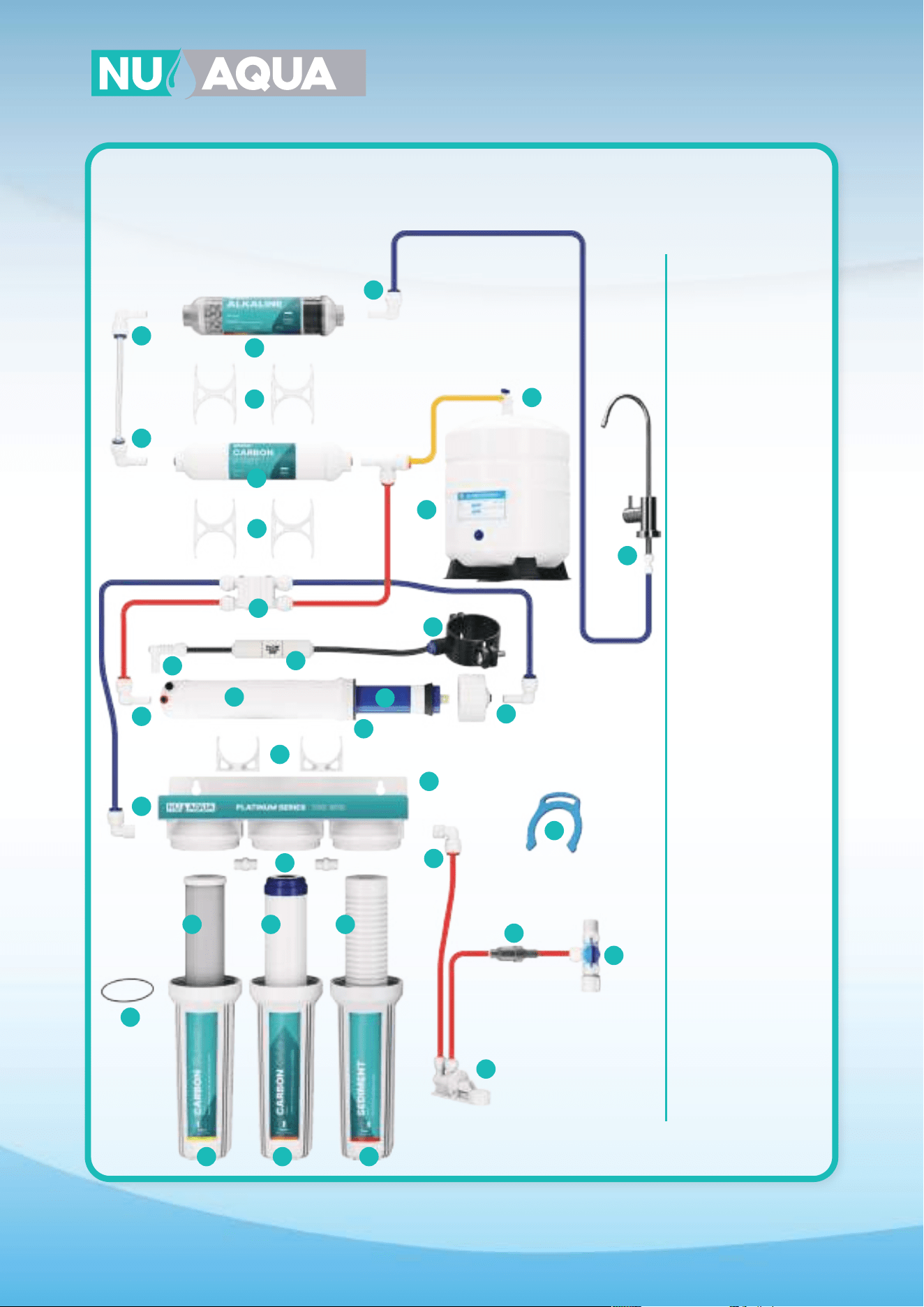
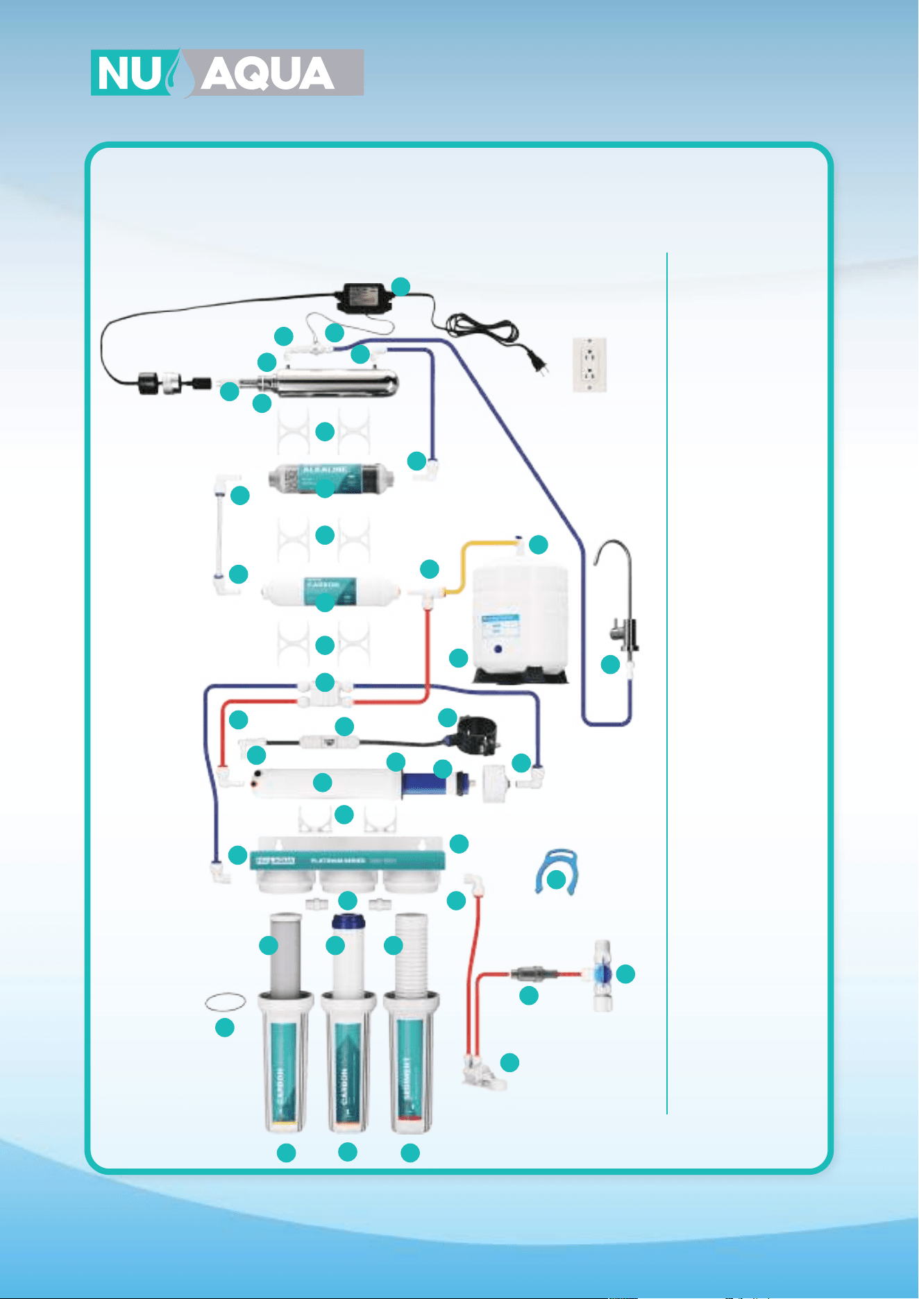
System Connections
5 Stage Connections
Product ID (SKU): WU-100GPD-NP, WU-100GPD-WP
A
H
J
G
F
E
I
D
C
B
A-B Connect red tubing to feed the water adapter and to the inlet of the filter protection valve.
C-D Connect red tubing from the outlet of the filter protection valve to the inlet of the leak detector.
E-F Connect red tubing from the outlet of the leak detector to the water inlet of the first stage.
G-H Connect yellow tubing from the T fitting on the post filter to the tank ball valve.
I-J Connect blue tubing from the outlet of the post filter to the faucet.
K-L Connect the black tubing from the flow restirctor to the drain saddle.
16
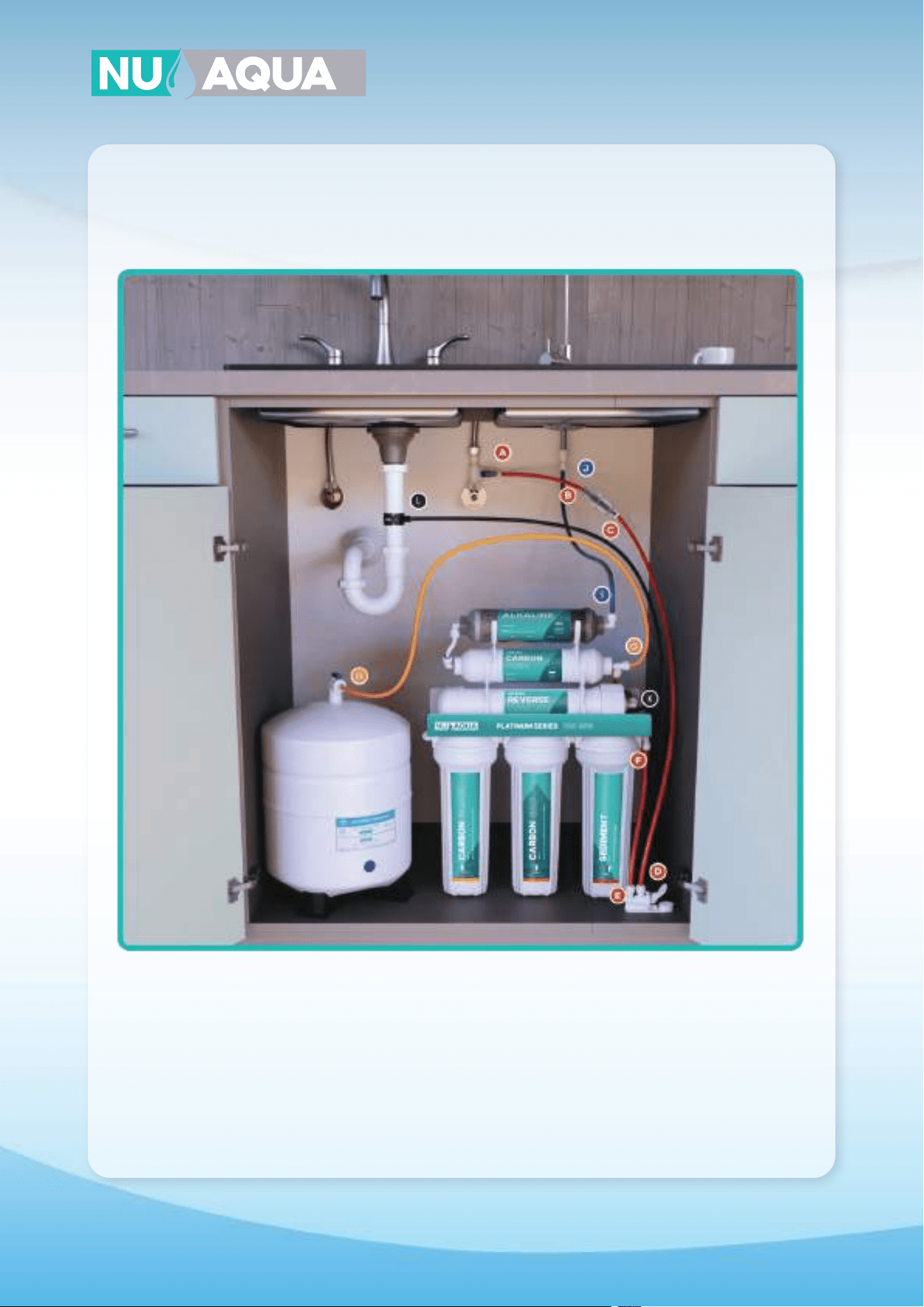
System Connections
6 Stage Alkaline Connections
For Product ID (SKU): WU-100GPD-NP-ALK
A
H
J
G
E
I
D
C
B
F
A-B Connect red tubing to feed the water adapter and to the inlet of the filter protection valve.
C-D Connect red tubing from the outlet of the filter protection valve to the inlet of the leak detector.
E-F Connect red tubing from the outlet of the leak detector to the water inlet of the first stage.
G-H Connect yellow tubing from the T fitting on the post filter to the tank ball valve.
I-J Connect blue tubing from the outlet of the alkaline filter to the faucet.
K-L Connect the black tubing from the flow restirctor to the drain saddle.
17
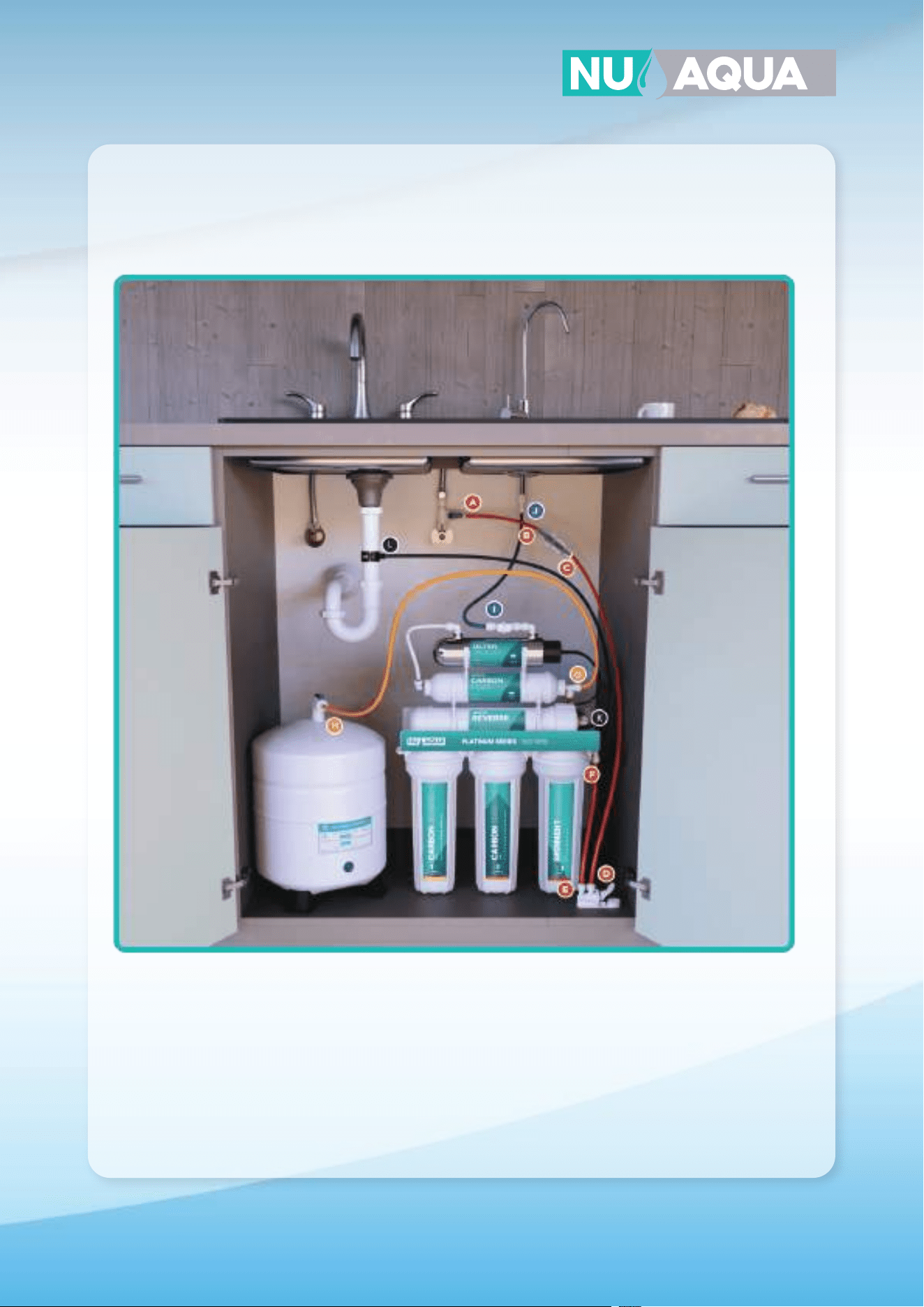
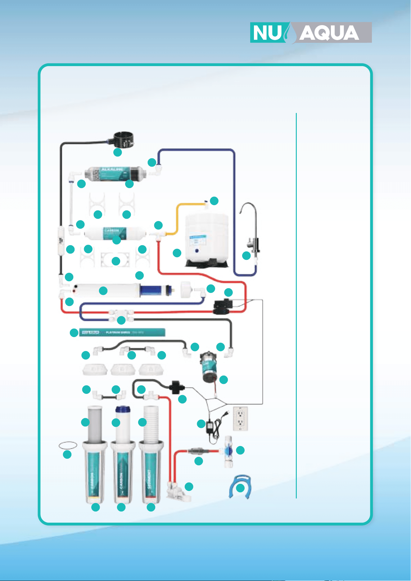
System Connections
6 Stage UV Connections
For Product ID (SKU): WU-100GPD-NP-UV
A
H
J
G
F
E
I
D
C
B
A-B Connect red tubing to feed the water adapter and to the inlet of the filter protection valve.
C-D Connect red tubing from the outlet of the filter protection valve to the inlet of the leak detector.
E-F Connect red tubing from the outlet of the leak detector to the water inlet of the first stage.
G-H Connect yellow tubing from the T fitting on the post filter to the tank ball valve.
I-J Connect blue tubing from the outlet of the UV filter to the faucet.
K-L Connect the black tubing from the flow restirctor to the drain saddle.
18
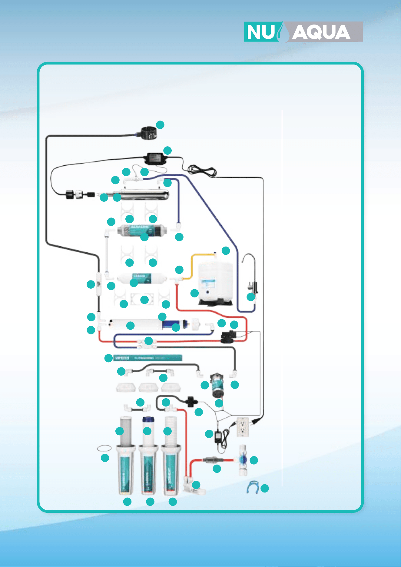
System Connections
7 Stage Connections
For Product ID (SKU): WU-100GPD-NP-UV-ALK
A H
J
G
E
I
D
C
B
F
A-B Connect red tubing to feed the water adapter and to the inlet of the filter protection valve.
C-D Connect red tubing from the outlet of the filter protection valve to the inlet of the leak detector.
E-F Connect red tubing from the outlet of the leak detector to the water inlet of the first stage.
G-H Connect yellow tubing from the T fitting on the post filter to the tank ball valve.
I-J Connect blue tubing from the outlet of the UV filter to the faucet.
K-L Connect the black tubing from the flow restirctor to the drain saddle.
19
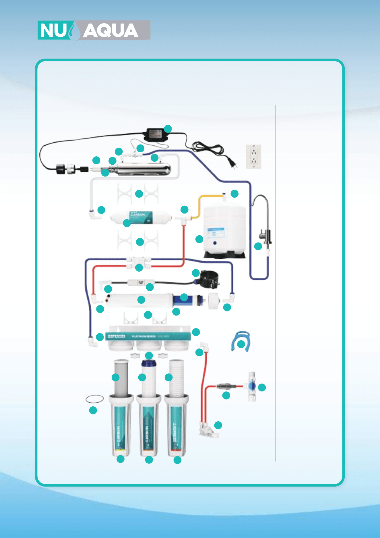
System Connections
5 Stage Pump Connections
For Product ID (SKU): WU-100GPD-WP
A
H
J
G
F
E
I
D
C
B
A-B Connect red tubing to feed the water adapter and to the inlet of the filter protection valve.
C-D Connect red tubing from the outlet of the filter protection valve to the inlet of the leak detector.
E-F Connect red tubing from the outlet of the leak detector to the water inlet of the first stage.
G-H Connect yellow tubing from the T fitting on the post filter to the tank ball valve.
I-J Connect blue tubing from the outlet of the post filter to the faucet.
K-L Connect the black tubing from the flow restirctor to the drain saddle.
20
System Connections
6 Stage Alkaline Pump Connections
For Product ID (SKU): WU-100GPD-WP-ALK
A
H
J
G
E
I
D
C
B
F
A-B Connect red tubing to feed the water adapter and to the inlet of the filter protection valve.
C-D Connect red tubing from the outlet of the filter protection valve to the inlet of the leak detector.
E-F Connect red tubing from the outlet of the leak detector to the water inlet of the first stage.
G-H Connect yellow tubing from the T fitting on the post filter to the tank ball valve.
I-J Connect blue tubing from the outlet of the alkaline filter to the faucet.
K-L Connect the black tubing from the flow restirctor to the drain saddle.
21
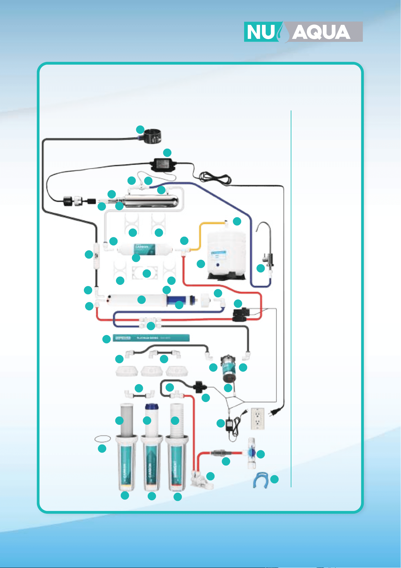
System Connections
6 Stage UV Pump Connections
For Product ID (SKU): WU-100GPD-WP-UV
A
H
J
G
F
E
I
D
C
B
A-B Connect red tubing to feed the water adapter and to the inlet of the filter protection valve.
C-D Connect red tubing from the outlet of the filter protection valve to the inlet of the leak detector.
E-F Connect red tubing from the outlet of the leak detector to the water inlet of the first stage.
G-H Connect yellow tubing from the T fitting on the post filter to the tank ball valve.
I-J Connect blue tubing from the outlet of the UV filter to the faucet.
K-L Connect the black tubing from the flow restirctor to the drain saddle.
22
System Connections
7 Stage Pump Connections
For Product ID (SKU): WU-100GPD-WP-UV-ALK
A
H
J
G
E
I
D
C
B
F
A-B Connect red tubing to feed the water adapter and to the inlet of the filter protection valve.
C-D Connect red tubing from the outlet of the filter protection valve to the inlet of the leak detector.
E-F Connect red tubing from the outlet of the leak detector to the water inlet of the first stage.
G-H Connect yellow tubing from the T fitting on the post filter to the tank ball valve.
I-J Connect blue tubing from the outlet of the UV filter to the faucet.
K-L Connect the black tubing from the flow restirctor to the drain saddle.
23
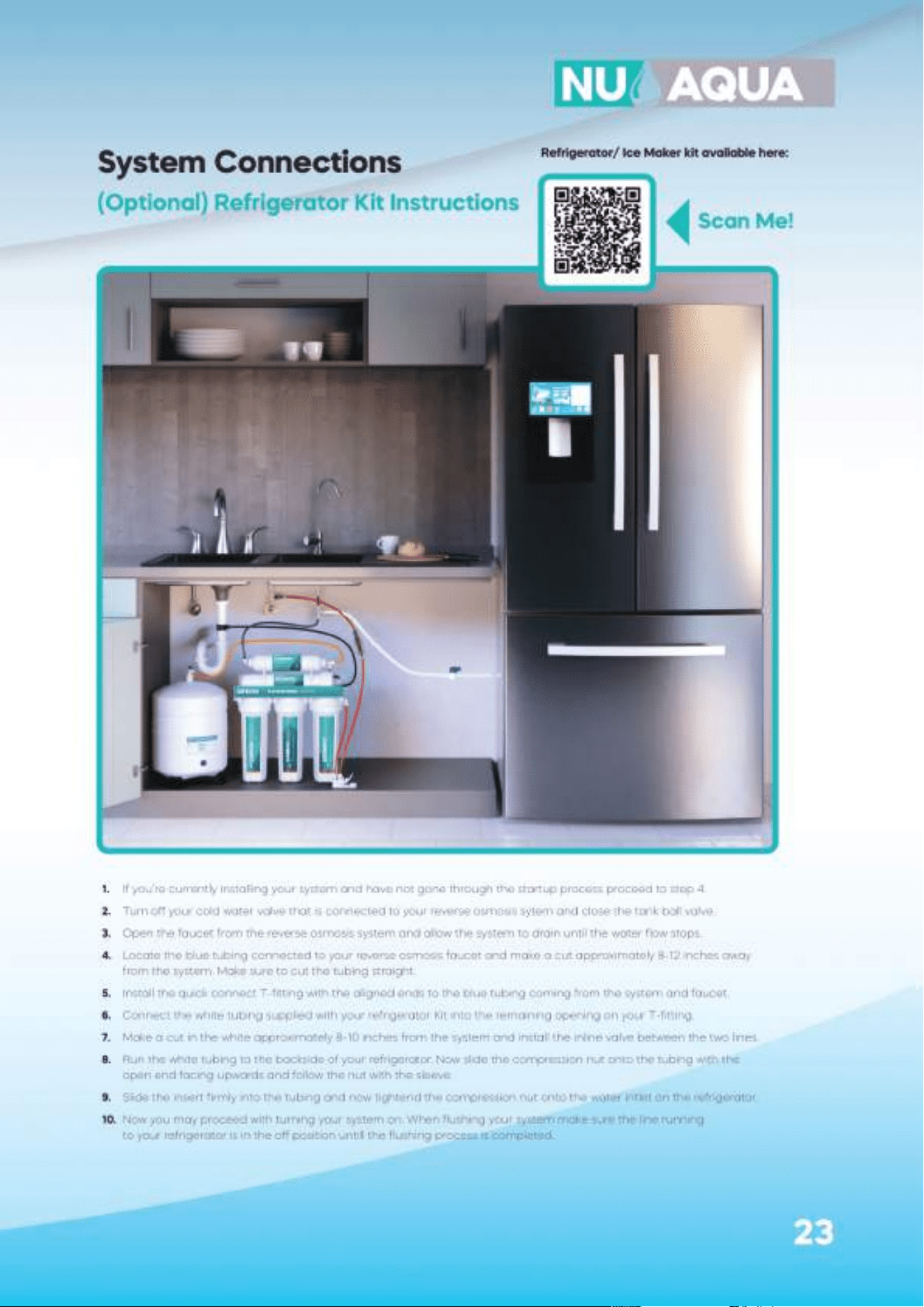
System Connections
(Optional) Refrigerator Kit Instructions
1. If you’re currently installing your system and have not gone through the startup process proceed to step 4.
2. Turn o your cold water valve that is connected to your reverse osmosis sytem and close the tank ball valve.
3. Open the faucet from the reverse osmosis system and allow the system to drain until the water flow stops.
4. Locate the blue tubing connected to your reverse osmosis faucet and make a cut approximately 8-12 inches away
from the system. Make sure to cut the tubing straight.
5. Install the quick connect T-fitting with the aligned ends to the blue tubing coming from the system and faucet.
6. Connect the white tubing supplied with your refrigerator Kit into the remaining opening on your T-fitting.
7. Make a cut in the white approximately 8-10 inches from the system and install the inline valve between the two lines.
8. Run the white tubing to the backside of your refrigerator. Now slide the compression nut onto the tubing with the
open end facing upwards and follow the nut with the sleeve.
9. Slide the insert firmly into the tubing and now tightend the compression nut onto the water intlet on the refrigerator.
10. Now you may proceed with turning your system on. When flushing your system make sure the line running
to your refrigerator is in the o position untill the flushing process is completed.
Scan Me!
Refrigerator/ Ice Maker kit available here:
24
System Startup
WARNING:
Before sending any water through your system fully check every connection
on the system. Remove any retaining clips and push the tubing into the quick
connect to ensure its fully inserted. Reinstall each retaining clip.
NOTE: DO NOT DRINK ANY WATER UNTIL COMPLETING THE FLUSHING PROCESS BELOW.
1. Turn the valve on your tank to the o position. This is to prevent any loose filters media from entering
your tank.
2. Open your cold water line fully then open your feed water adapter.
3. If your system is equiped with a booster pump plug in the electrical cord into your outlet.
4. If your system is equiped with a UV filter plug the electrical cord into your outlet.
5. Turn the handle on your reverse osmosis faucet to the open position. This may take up to 10 minutes
for water to begin to drip from the faucet. Once water begins to drip, let it run for 30 minutes.
6. After 30 minutes have passed close the reverse osmosis faucet and wait 10 minutes for the system
to pressurize. Once pressurized feel and visually check each fitting and connection for leaks.
If no leaks are present, proceed. If you do have a leak, locate the source and turn o the cold water valve.
Address the leak, if unable to resolve, contact our customer support.
7. Turn the tank ball valve to the open position.
8. Wait for the tank to fill, this will take approximately 1-3 hours.
9. Now that the tank is full, flush the system by opening the reverse osmosis faucet until the storage tank is
completely drained. The water flow will be reduced to a slow trickle once the tank is empty.
10. Repeat steps 6-7 three to five times to ensure your system is properly flushed. Once completed your system
is ready for use.
IMPORTANT: Check for leaks daily during the first two weeks after installation.
NOTE: Your water may have a slightly milky color during the first week of use. This is caused
by tiny air bubbles in the water and will go away with use.
NOTE: If your system has an alkaline filter your water’s TDS will register higher. For accurate
testing, test water that has not been processed by the alkaline filter.
25
Prefilers Stage 1-3
1. Turn o the cold water valve that your system is connected to and open the reverse osmosis faucet to drain
the system. Unplug your system if it has a booster pump or UV filter.
2. Place your system in a small bucket or water collection tray and loosen stages 1-3 with your housing wrench.
3. Remove and discard the old filters.
4. Using dish soap wash the prefilter housings. Thoroughly rinse the housings to ensure all the soap is removed.
5. Wash your hands before unwrapping and handling your new replacement filters.
6. Unwrap and drop in your new replacement filters in their housing.
7. Before tightening the housings make sure that each housing has it’s o-ring in the correct location.
8. Tighten the filter housings using your housing wrench.
9. If you’re not replacing any other filters follow the system restart procedure on page 21.
Membrane
1. Turn o the cold water valve that your system is connected to and open the reverse osmosis faucet to drain
the system. Unplug plug your system if it has a booster pump or UV filter.
2. Place your system in a small bucket or water collection tray and loosen stages 1-3 with your housing wrench.
3. Disconnect the red tubing from the membrane housing cap and open the membrane housing with the
housing wrench.
4. Pull out the old membrane. You may need pliers to help pull out the membrane.
4. Push in the new membrane firmly into the housing. Tighten the housing cap with your housing wrench.
5. If you’re not replacing any other filters follow the system restart procedure on page 21.
Post Filter
NOTE: Make sure you’ve already turned o your system. If not follow step #1 from Prefilters.
1. Disconnect your tubing from both ends of the filter and remove the push fittings from the filter.
2. Remove the old filter from the housing clips and discard.
3. Attach your new post filter to the housing clips in the same orientation as the one previously removed.
4. Reinsert the two push fittings from your older filter and attach your tubing.
5. If you’re not replacing any other filters follow the system restart procedure on page 21.
Alkaline Filter
NOTE: Make sure you’ve already turned o your system. If not follow step #1 from Prefilters.
1. Disconnect your tubing from both ends of the filter and remove the push fittings from the filter.
2. Remove the old filter from the housing clips and discard.
3. Attach your new alkaline filter to the housing clips in the same orientation as the one previously removed.
4. Reinsert the two push fittings from your older filter and attach your tubing.
5. If you’re not replacing any other filters follow the system restart procedure on page 21.
UV Filter
NOTE: DO NOT unscrew the UV filters metal cap. This is not needed to change the bulb.
1. Make sure the UV power cord is unplugged from the power outlet.
2. Slide o the black plastic cap o of the UV filter and slide the bulb out of the filter housing.
3. Unplug and discard the old bulb.
4. Connect new bulb to power supply and slide into filter housing. Reinstall black plastic cap.
Filter Changes
WANT YOUR FILTERS DELIVERED AUTOMATICALLY?
JOIN THE FILTER CLUB AND GET YOUR FILTERS
AT A DISCOUNT.
Scan Me!
NOTE:
It is not necessary to disconnect the automatic shut o valve during a filter
change. If you do disconnect it refer to system diagrams on page 28-35.
WARNING: Do not look directly at UV light. Avoid skin and eye exposure.
Always unplug power before performing any maintenance.
26
To keep your system in the best operating conditions it’s recommended that you sanitize your system once every 12
months. We recommend using Sani Systems liquid sanitizer.
NOTE: Make sure you’ve already turned o your system. If not follow step #1 from Prefilters on page 22.
1. You should sanitize your system during a complete filter replacement.
2. Turn o the cold water supply line to your system.
3. Open your reverse osmosis faucet to drain the system.
4. Once the flow from your faucet has stopped remove your stage 1 sediment filter, stage 2 GAC filter,
stage 3 carbon block filter, and reverse osmosis membrane. Do not remove the stage 5 carbon post filter.
5. Follow Sani Systems solution instructions to mix solution with water.
6. Fill stages 1-3 prefilter housings with your mixed solution and reinstall the housings onto the system.
7. Close the reverse osmosis faucet, turn on the cold water supply line, and let your system run for 10
minutes. Make sure your tank is in the open position so that your tank is sanitized. After holding tank is full,
let system stand idle for a minimum of 60 seconds.
8. Open your reverse osmosis faucet and let your system drain for approximately 10 minutes.
9. Close the reverse osmosis faucet and allow tank to refill before draining the system.
10. Repeat steps 8-9 at least 2 times to completely flush the system.
11. Your system is not completely sanitize. You may now proceed with replacing your filters.
Vacation Mode
1-2 Weeks
Turning o your system
1. Turn o your feed water valve and unplug any electrical cords coming from your system if you have a
booster pump or UV filter.
Turning on your system
1. Open the feed water adapter and reconnect your electrical plugs if applicable.
2. Flush your system 2-3 times to reactivate your filters.
1+ Months
Turning o your system
1. Turn o your feed water valve and unplug any electrical cords coming from your system if you have a
booster pump or UV filter.
2. Open the reverse osmosis faucet and fully drain the system.
3. Remove each filter from your system and place them vertically to allow them to dry.
4. Once dry, plastic wrap each filter air tight and store them in the refrigerator. Only store filters less than 3
months old. If they’re older than 3 months its best to replace the filter.
5. Leave the filter housings o to ensure the system drys to prevent bacteria from growing.
Turning on your system
1. Thoroughly wash your filter housings and reinstall your filters. Turn on your feed water valve.
2. Flush your system 2-3 times to reactivate your filters.
Sanitizing Your System
Troubleshooting
Problem
Milky colored water
Air bubbles in water
Loud or noisy system
Slow production or no water
from RO faucet
Water taste or an
oensive smell
No drain water
Leaks
No water
Tank not filling
UV light
not turning on
Solution
• Air in the system is normal with initial
installation and startup. This will clear up
within 1 to 2 weeks.
• Will disappear after system shutdown.
• Relocate drain saddle above P-trap.
• Blockage sometimes caused by debris
from garbage disposal or dishwasher.
•Normally it takes 1-3 hours to fill the
tank. Low water pressure and/or
temperature
can reduce production rate.
• Add pressure to the storage tank. The
pressure should be 7-10 PSI when the
tank is empty.
• Add a booster pump.
• Make sure tubing is straight.
• Replace prefilters.
• Replace RO membrane.
• Check for clog in drain line and clear.
•Replace inline carbon filter.
•Replace RO membrane.
• Replace the flow restrictor.
• Tighten fittings as necessary.
• Replace the O-ring.
. Realign drain saddle.
. Replace teflon tape with 7-10 wraps.
• Replace leak stop valve.
• Check water flows from feed water
adapter. If no water comes through,
replace the feed water adapter
• Connect the tank directly to feed
water adapter and fill for 1 minute. This
will help prime the tank
• Test on a new outlet that is known
to be working.
• Replace UV bulb
• Contact support
Causes
• Air in the system
• Air gap faucet
• Location of drain saddle
• Restrictions in drain line
• System just starting up
• Air pressure in water storage
tank is low
• Tank valve is closed
• Low water pressure
• Crimps in tubing
• Clogged prefilters
• Fouled RO membrane
• Drain line clogged
• Inline post carbon filter is depleted
• Fouled RO membrane
• Clogged flow restrictor
• Fittings are not tightened
• Twisted/damaged O-ring
• Misalignment of hole in drain saddle
• Threaded connections
• Check leak stop valve
• Check feed water adapter valve
• Tank needs to be primed
• Low incoming water pressure
• Faulty ballast
• Plug shared with garbage
disposal
27
28
16
16
10
10
11
27
1
17
13
14
15
12
2
3
28
5
5
5
6
22
23
21
20
19
16
24
25
26
1. WU-RCLIP
2. WU-FWA-02
3. WU-14LSV
4. WU-FH10-CLEAR-SL
5. WU-FH10-WHITE-SL
6. WU-FHRING-SL
7. WU-S-1M
8. WU-GAC-1M
9. WU-CB-5M
10. WU-14X14-ELB
11. WU-AHN-0202
12. WU-CL-204-T
13. WU-CHK-VLV-PF
14. WU-FL-300
15. WU-14DS
16. WU-14PF
17. WU-MHP-1812-PF
18. WU-MHP-OR-SL
19. WU-100GPD-MB
20. WU-14-ASOV
21. WU-2.5X2CLP
22. WU-PST
23. WU-14X14XPF
24. WU-BV-14
25. WU-4GTANK
26. WU-FAU-606CP
27. WU-NP-BRKT
28. WU-FPV-70
18
78
9
System Diagrams
5 Stage
For Product ID (SKU): WU-100GPD-NP
29
18
18
18
10
11
11
11
11
11
27
1
17
13
14
15
12
2
3
555
6
7
89
22 22
23
28
21
20
19
16
24
25
26
1. WU-RCLIP
2. WU-FWA-02
3. WU-14LSV
4. WU-FH10-CLEAR-SL
5. WU-FH10-WHITE-SL
6. WU-FHRING-SL
7. WU-S-1M
8. WU-GAC-1M
9. WU-CB-5M
10. WU-WP-T
11. WU-14X14-ELB
12. WU-WP-BRKT
13. WU-PUMP
14. WU-PUMP-LPS
15. WU-PUMP-HPS
16. WU-14-ASOV
17. WU-CHK-VLV-PF
18. WU-14-PF
19. WU-MHP-1812-PF
20. WU-MHP-OR-SL
21. WU-CL-204-T
22. WU-2.5X2CLP
23. WU-PST
24. WU-14X14XPF
25. WU-BV-14
26. WU-46GTANK
27. WU-FAU-606CP
28. WU-14DS
28. WU-PUMP-PS
29. WU-FPV-40
System Diagrams
5 Stage with Pump
For Product ID (SKU): WU-100GPD-WP
28
29
30
16
16
16
16
10
10
11
27
28
1
17
13
14
15
12
2
30
3
555
6
22
21
20
19
16
24
25
26
1. WU-RCLIP
2. WU-FWA-02
3. WU-14LSV
4. WU-FH10-CLEAR-SL
5. WU-FH10-WHITE-SL
6. WU-FHRING-SL
7. WU-S-1M
8. WU-GAC-1M
9. WU-CB-5M
10. WU-14X14-ELB
11. WU-AHN-0202
12. WU-CL-204-T
13. WU-CHK-VLV-PF
14. WU-FL-300
15. WU-14DS
16. WU-14PF
17. WU-MHP-1812-PF
18. WU-MHP-OR-SL
19. WU-100GPD-MB
20. WU-14-ASOV
21. WU-2.5X2CLP
22. WU-PST
23. WU-14X14XPF
24. WU-BV-14
25. WU-4GTANK
26. WU-FAU-606CP
27. WU-2X2-CLP
28. WU-ALK-FO
29. WU-NP-BRKT
30. WU-FPV-70
18
789
29
System Diagrams
6 Stage Alkaline
For Product ID (SKU):
WU-100GPD-NP-ALK
31
18
18
18
18
18
10
11
11 1111
11 11
11
27
1
17
13
14
15
12
2
33
3
555
6
7
8
9
22
30
31
22
28
29
28
21
23
20
19
16
24
25
26
1. WU-RCLIP
2. WU-FWA-02
3. WU-14LSV
4. WU-FH10-CLEAR-SL
5. WU-FH10-WHITE-SL
6. WU-FHRING-SL
7. WU-S-1M
8. WU-GAC-1M
9. WU-CB-5M
10. WU-WP-T
11. WU-14X14-ELB
12. WU-WP-BRKT
13. WU-PUMP
14. WU-PUMP-LPS
15. WU-PUMP-HPS
16. WU-14-ASOV
17. WU-CHK-VLV-PF
18. WU-14-PF
19. WU-MHP-1812-PF
20. WU-MHP-OR-SL
21. WU-CL204-T
22. WU-2.5X2CLP
23. WU-PST
24. WU-14X14XPF
25. WU-BV-14
26. WU-4GTANK
27. WU-FAU-606CP
28. WU-2X2-CLP
29. WU-ALK-FO
30. WU-FL-300
31. WU-14DS
32. WU-PUMP-PS
33. WU-FPV-40
System Diagrams
6 Stage with Pump
For Product ID (SKU): WU-100GPD-WP-ALK
32
32
16
31
32
16
10
10
11
27
28
28
1
17
13
14
15
12
2
35
3
5
5
5
6
22
23
21
20
19
16
24
25
26
18
789
System Diagrams
6 Stage Ultraviolet
For Product ID (SKU): WU-100GPD-NP-UV
29
1. WU-RCLIP
2. WU-FWA-02
3. WU-14LSV
4. WU-FH10-CLEAR-SL
5. WU-FH10-WHITE-SL
6. WU-FHRING-SL
7. WU-S-1M
8. WU-GAC-1M
9. WU-CB-5M
10. WU-14X14-ELB
11. WU-AHN-0202
12. WU-CL-204-T
13. WU-CHK-VLV-PF
14. WU-FL-300
15. WU-14DS
16. WU-14PF
17. WU-MHP-1812-PF
18. WU-MHP-OR-SL
19. WU-100GPD-MB
20. WU-14-ASOV
21. WU-2.5X2CLP
22. WU-PST
23. WU-14X14XPF
24. WU-BV-14
25. WU-4GTANK
26. WU-FAU-606CP
27. WU-2X2-CLP
28. WU-14X14-QC
29. WU-FLW-S
30. WU-UV-GLASS
31. WU-UV-ORING
32. WU-UV-BULB
33. WU-UV-BLST
34. WU-NP-BRKT
35. WU-FPV-70
33
30
34
33
31
32
16
10
1111
11
11 11
27
28 28
1
17
13
14
15
12
2
39
3
5
5
5
6
22 22
23
21
20
19
36
24
25
26
18
18
38
7
8
9
System Diagrams
6 Stage Ultraviolet with Pump
For Product ID (SKU): WU-100GPD-WP-UV
29
1. WU-RCLIP
2. WU-FWA-02
3. WU-14LSV
4. WU-FH10-CLEAR-SL
5. WU-FH10-WHITE-SL
6. WU-FHRING-SL
7. WU-S-1M
8. WU-GAC-1M
9. WU-CB-5M
10. WU-WP-T
11. WU-14X14-ELB
12. WU-WP-BRKT
13. WU-PUMP
14. WU-PUMP-LPS
15. WU-PUMP-HPS
16. WU-14-ASOV
17. WU-CHK-VLV-PF
18. WU-14-PF
19. WU-MHP-1812-PF
20. WU-MHP-OR-SL
21. WU-CL-204-T
22. WU-2.5X2CLP
23. WU-PST
24. WU-14X14XPF
25. WU-BV-14
26. WU-4GTANK
27. WU-FAU-606CP
28. WU-2X2-CLP
29. WU-FLW-S
30. WU-FL-300
31. WU-UV- BLST
32. WU-14DS
33. WU-UV-BULB
34. WU-UV-GLASS
35. WU-UV-ORING
36. WU-100GPD-MB
37. WU-PUMP-PS
38 WU-14X14-QC
39. WU-FPV-40
33
34
35
30
18
37
38
33
31
32
16
10
1111
11
11 11
27
28 28
1
17
13
14
15
12
2
39
3
5
5
5
6
22 22
23
21
20
19
36
24
25
26
18
18
38
7
8
9
System Diagrams
6 Stage Ultraviolet with Pump
For Product ID (SKU): WU-100GPD-WP-UV
29
1. WU-RCLIP
2. WU-FWA-02
3. WU-14LSV
4. WU-FH10-CLEAR-SL
5. WU-FH10-WHITE-SL
6. WU-FHRING-SL
7. WU-S-1M
8. WU-GAC-1M
9. WU-CB-5M
10. WU-WP-T
11. WU-14X14-ELB
12. WU-WP-BRKT
13. WU-PUMP
14. WU-PUMP-LPS
15. WU-PUMP-HPS
16. WU-14-ASOV
17. WU-CHK-VLV-PF
18. WU-14-PF
19. WU-MHP-1812-PF
20. WU-MHP-OR-SL
21. WU-CL-204-T
22. WU-2.5X2CLP
23. WU-PST
24. WU-14X14XPF
25. WU-BV-14
26. WU-4GTANK
27. WU-FAU-606CP
28. WU-2X2-CLP
29. WU-FLW-S
30. WU-FL-300
31. WU-UV- BLST
32. WU-14DS
33. WU-UV-BULB
34. WU-UV-GLASS
35. WU-UV-ORING
36. WU-100GPD-MB
37. WU-PUMP-PS
38 WU-14X14-QC
39. WU-FPV-40
33
34
35
30
18
37
38
34
16
16
16
31
32
16
10
1011
27
27
35
28
1
17
13
14
15
12
2
36
3
5
55
6
22
23
21
20
19
16
24
25
26
18
789
System Diagrams
7 Stage
For Product ID (SKU): WU-100GPD-NP-UV-ALK
29
29
1. WU-RCLIP
2. WU-FWA-02
3. WU-14LSV
4. WU-FH10-CLEAR-SL
5. WU-FH10-WHITE-SL
6. WU-FHRING-SL
7. WU-S-1M
8. WU-GAC-1M
9. WU-CB-5M
10. WU-14X14-ELB
11. WU-AHN-0202
12. WU-CL-204-T
13. WU-CHK-VLV-PF
14. WU-FL-300
15. WU-14DS
16. WU-14PF
17. WU-MHP-1812-PF
18. WU-MHP-OR-SL
19. WU-100GPD-MB
20. WU-14-ASOV
21. WU-2.5X2CLP
22. WU-PST
23. WU-14X14XPF
24. WU-BV-14
25. WU-4GTANK
26. WU-FAU-606CP
27. WU-2X2-CLP
28. WU-ALK-FO
29. WU-14X14-QC
30. WU-FLW-S
31. WU-UV-GLASS
32. WU-UV-ORING
33. WU-UV-BULB
34. WU-UV-BLST
35. WU-NP-BRKT
36. WU-FPV-70
33
30
34
35
31
37
32
16
1011
11
11
11
11
27
28 28
28 28
17
13
14
15
12
2
1
39
3
5 55
6
22
22
23
21
20
19
36
24
25
26
18
18
18
18
7
8
9
System Diagrams
7 Stage with Pump
For Product ID (SKU): WU-100GPD-WP-UV-ALK
29
1. WU-RCLIP
2. WU-FWA-02
3. WU-14LSV
4. WU-FH10-CLEAR-SL
5. WU-FH10-WHITE-SL
6. WU-FHRING-SL
7. WU-S-1M
8. WU-GAC-1M
9. WU-CB-5M
10. WU-WP-T
11. WU-14X14-ELB
12. WU-WP-BRKT
13. WU-PUMP
14. WU-PUMP-LPS
15. WU-PUMP-HPS
16. WU-14-ASOV
17. WU-CHK-VLV-PF
18. WU-14X14-QC
19. WU-MHP-1812-PF
20. WU-MHP-OR-SL
21. WU-CL-204-T
22. WU-2.5X2CLP
23. WU-PST
24. WU-14X14XPF
25. WU-BV-14
26. WU-4GTANK
27. WU-FAU-606CP
28. WU-2X2-CLP
29. WU-FLW-S
30. WU-FL-300
31. WU-UV-BLST
32. WU-14DS
33. WU-UV-BULB
34. WU-UV-GLASS
35. WU-UV-ORING
36. WU-100GPD-MB
37. WU-ALK-FO
38. WU-PUMP-PS
39. WU-FPV-40
33
34
35
30
18
18
38
18
36
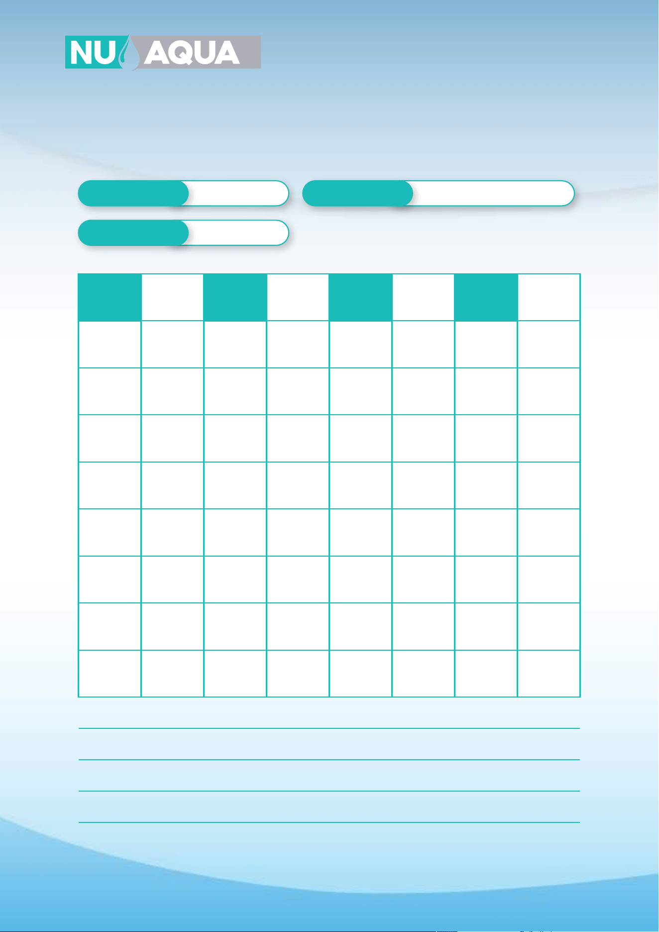
Service Record
Date of Purchase
Date of Install
Installed By
DATE 2 ST STAGE
CARBON
GAC
RO
MEMBRANE
ALKALINE
FILTER
3 ST STAGE
CARBON
BLOCK
5 ST STAGE
CARBON POST
FILTER
UV
BULB
1 ST STAGE
SEDIMENT
NOTES:
37
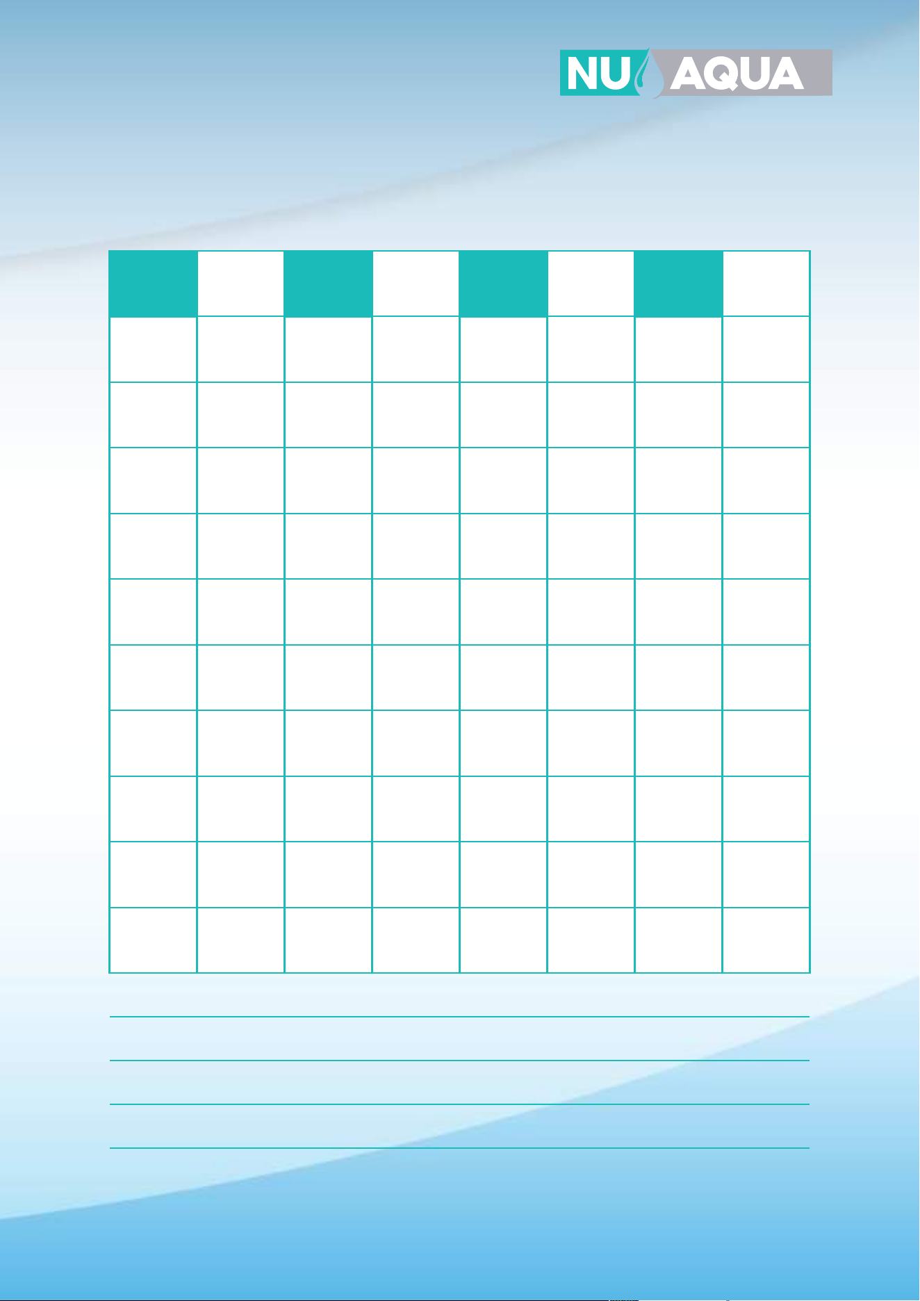
Service Record
DATE 2 ST STAGE
CARBON
GAC
RO
MEMBRANE
ALKALINE
FILTER
3 ST STAGE
CARBON
BLOCK
5 ST STAGE
CARBON POST
FILTER
UV
BULB
1 ST STAGE
SEDIMENT
NOTES:
38
Limited Product Warranty
SCOPE
NU Aqua Systems takes pride in selling the highest quality reverse osmosis system (“Product”) on the market. As such, NU Aqua
Systems expressly warrants to the original purchaser that, for a period of three (3) years from the date of purchase, the Product
will be reasonably free of defects in materials and workmanship. Within that three (3) year period from the original purchase,
NU Aqua Systems will, at its option, repair or replace the Product without charge, or refund the cost of the Product, if the
Product fails or does not perform as warranted solely due to a manufacturing defect within the warranty period, subject to the
limitations and exclusions set forth in this Limited Product Warranty. This Limited Product Warranty only applies when the
Product is used, stored, handled, fabricated and/or installed in the manner recommended by NU Aqua Systems in the Installa-
tion Instruction & Owner's Manual (“Manual”).
REPAIR OR REPLACEMENT
Repair or replacement during this three (3) year warranty does not include labor charges, freight charges or any other local
charges from third parties other than NU Aqua Systems, unless NU Aqua Systems expressly approves such charges in writing.
During the entire three (3) year warranty, NU Aqua Systems's obligation to repair or replace shall further be limited to repair or
replacement with the styles, models, products, colors, etc. of the Product that are available at the time of the repair or replace-
ment, and shall be limited to the repair or replacement of only the specific Product that fails due to a manufacturing defect.
Any repaired or replaced product shall also remain subject to the original three (3) year warranty from the date of the original
purchase, and any repair or replacement shall not extend the original warranty period in any manner or start a new warranty
period.
CONDITIONS OF VALIDITY OF THIS LIMITED PRODUCT WARRANTY
Even though the Product has extremely high endurance for operating conditions such as pH, maximum TDS, temperature, and
optimum water pressure,
THIS LIMITED PRODUCT WARRANTY SHALL ONLY BE VALID IF:
1. The replaceable filters and membrane are changed and maintained on a regular basis as directed in the
Manual. Moreover, depending on local water input water quality, regular maintenance may need to be increased.
2. The Product is operated within the confines of the following feed water conditions:
• Water Pressure: 45 - 80 PSI (No Pump Systems) and 15-45 PSI (Booster Pump Systems)
• PH Range: 2-11 Max. TDS: 1000 PPM Water Temperature: 40°-100° F SDI: 5
Any information or suggestion by NU Aqua Systems with respect to the Product concerning applications, specifications or
compliance with codes and standards is provided solely for your convenient reference and is made without any representation
as to accuracy or suitability. You must verify and test the suitability of any information with respect to the Product for your
specific application.
NON-COVERED DEFECTS
THIS LIMITED PRODUCT WARRANTY DOES NOT COVER DEFECTS CAUSED BY:
1. Improper storage, installation, maintenance, handling, use and/or alterations of the Product, including, but not limited to,
noncompliance with the installation, maintenance and standard operation conditions stated in the Manual and this Limited
Product Warranty.
2. Unreasonable use, unintended use, or misuse of the Product for something other than its intended purpose as a reverse
osmosis system.
3. Use of replacement parts, filters, membranes or other accessories that are not sold or manufactured by NU Aqua Systems
for use with this particular Product.
4. Damage not resulting from manufacturing defects that occur while the Product is in the original purchaser's possession.
5. Installation of the Product with known or visible manufacturing defects at the time of installation.
6. Damage caused by freezing, flood, fire or Act of God.

39
Conditions That Render This Limited Product Warranty Void
THIS LIMITED PRODUCT WARRANTY SHALL BE VOID IF:
1. The Product is not operated in compliance with normal municipal water conditions for which the particular model of this
Product is intended.
2. The person seeking to invoke the warranty is not the original purchaser. That is, this Limited Product Warranty only extends
to original purchasers.
3. The Product is purchased used. That is, this Limited Product Warranty only covers new products.
4. The Product is purchased from someone other than NU Aqua Systems or one of NU Aqua Systems authorized dealers. This
is because, unless the Product was sold by NU Aqua Systems or one of its authorized dealers, NU Aqua Systems cannot verify
or guarantee the integrity or authenticity of the Product.
GENERAL CONDITIONS
The warranties set forth herein are the only warranties made by NU Aqua Systems in connection with the product. NU Aqua
Systems cannot and does not make any implied or express warranties with respect to the product, and disclaims all other
warranties, including, but not limited to, any warranty of merchantability or fitness for a particular purpose. Products sold by NU
Aqua Systems are sold only to the specifications specifically set forth by NU Aqua Systems in writing. Other than the limited
product warranty set forth herein, NU Aqua Systems makes no other warranties, express or implied. NU Aqua Systems’s sole
obligation under this warranty shall be repair or replacement of a non-conforming product or parts of the product, or at the
option of NU Aqua Systems, return of the product and a refund of the purchase price. Buyer assumes all risk whatsoever as to
the result of the use of the product purchased, whether used singularly or in combination with any other products or substances.
No claim by the buyer/owner of any kind, including claims for indemnification, shall be greater in amount than the purchase
price of the products in respect to which damages are claimed. In no event shall NU Aqua Systems be liable to buyer/owner in
tort, contract or otherwise, for any special, indirect, incidental, consequential, reliance, statutory, special, punitive or exemplary
damages, including, but not limited to, lost profits, loss of use, loss of time, inconvenience, damage to goodwill or reputation, or
loss of data, even if advised of the possibility of such damages or such damages could have been reasonably foreseen, in
connection with, arising out of, or as a result of, the sale, delivery, servicing, use or loss of use of the products sold hereunder, or
for any liability of buyer to any third party with respect thereto.
In case some states do not allow the exclusion or limitation of incidental or consequential damages, you may choose to return
the Product. If you choose to keep it, you insist this exclusion still applies to you.
OBTAINING WARRANTY COVERAGE OR GENERAL INQUIRIES
If coverage is available, you may obtain coverage under this Limited Product Warranty by providing NU Aqua Systems with
proof of original purchase, and that you are the original purchaser. For service under this Limited Product Warranty, you must
notify NU Aqua Systems by phone at 1-888-621-0460, by email at support@nuaquasystems.com. In making the claim, please
provide your name, address, phone number, a description of the product involved, and an explanation of the defect.
LIMITED LIFETIME* WARRANTY
NU Aqua Systems provides a Limited Lifetime* Warranty when original purchaser enrolls in the NU Aqua Systems Filter Club
Subscription service and changes the Product's filters at the recommended cadence with genuine NU Aqua System replace-
ment filters. The lifetime warranty does not cover normal wear and tear parts such as O-Rings, fittings, tubing, filters, faucets
and teflon tape.
*The term Lifetime refers to the lifetime of the Product. This does not mean the purchaser's lifetime, but rather the expected
lifetime of the Product. The expected lifetime of the Product is 10 Years. However, at NU Aqua Systems discretion, we may cover
warranty claims in excess of the Product expected lifetime.