Hearth & Home Technologies • Fireside Burner/Hearth Kits • 4004-304 Rev J • 01/2022
1
tm
tm
Models:
MHK18NG
MHK24NG
STMHK18NG
STMHK24NG
Fireside Burner/Hearth Kits
For Natural Gas Use Only
Installation
Instructions
Check with your local building code agency before you begin installation to ensure compliance with local codes, including the need
for permits and follow-up inspections. If you encounter any problems regarding code approvals, or if you need clarication of any of
the instructions contained here, contact the Technical Services Dept., Hearth & Home Technologies Inc., phone 1-888-427-3973 or
1-800-927-6841.
DO NOT DISCARD THIS MANUAL
CAUTION
• Important operating and
maintenance instructions
included.
•
Leave this manual with
party responsible for use
and operation.
•
Read, understand
and follow these
instructions for safe
installation and
operation.
DO NOT
DISCARD
If the information in these instruc-
tions is not followed exactly, a
re may result causing property
damage, personal injury, or death.
• Do not store or use gasoline or other ammable
vapors and liquids in the vicinity of this or any
other appliance.
• What to do if you smell gas:
- Do
not try to light any appliance.
- Do not touch any electrical switch. Do not
use any phone in your building.
- Immediately call your gas supplier from a
neighbor’s phone. Follow the gas supplier’s
instructions.
- If you cannot reach your gas supplier, call the
re department.
• Installation and service must be performed by
a qualied installer, service agency, or the gas
supplier.
WARNING
HOT! DO NOT TOUCH.
SEVERE BURNS MAY RESULT.
CLOTHING IGNITION MAY RESULT.
WARNING
• Keep children away.
• CAREFULLY SUPERVISE children in same room as
appliance.
• Alert children and adults to hazards of high temperatures.
• Keep clothing, furniture, draperies and other combustibles
away.
Glass and other surfaces are hot during operation
and cool down.
Installation and service of this appli-
ance should be performed by qualied
personnel. Hearth & Home Tech-
nologies suggests NFI certified or
factory-trained professionals, or tech-
nicians supervised by
an NFI certied pro-
fessional.
In the Commonwealth of Massachusetts:
• is appliance must be installed by a licensed plumber or gas
tter.
• e chimney ue damper, when used with gas logs, will be
welded open or completely removed.
• A CO detector shall be installed in the room where the appliance
is installed.
Hearth & Home Technologies • Fireside Burner/Hearth Kits • 4004-304 Rev J• 01/2022
2
Read this manual before installing or operating this appliance.
Please retain this owner’s manual for future reference.
Congratulations on selecting a Hearth & Home Technologies gas
log set—an elegant and clean alternative to burning wood. e
Hearth & Home Technologies gas log set you have selected is de-
signed to provide the utmost in safety, reliability, and eciency.
As the owner of this new gas log set, you’ll want to read and care-
fully follow all of the instructions contained in this owner’s manu-
al. Pay special attention to all cautions and warnings.
is owner’s manual should be retained for future reference. We
suggest you keep it with your other important documents and
product manuals.
e information contained in this owner’s manual, unless noted
otherwise, applies to all models and gas control systems.
Your new gas log set will give you years of durable use and trou-
ble-free enjoyment. Welcome to the Hearth & Home Technologies
family of appliance products!
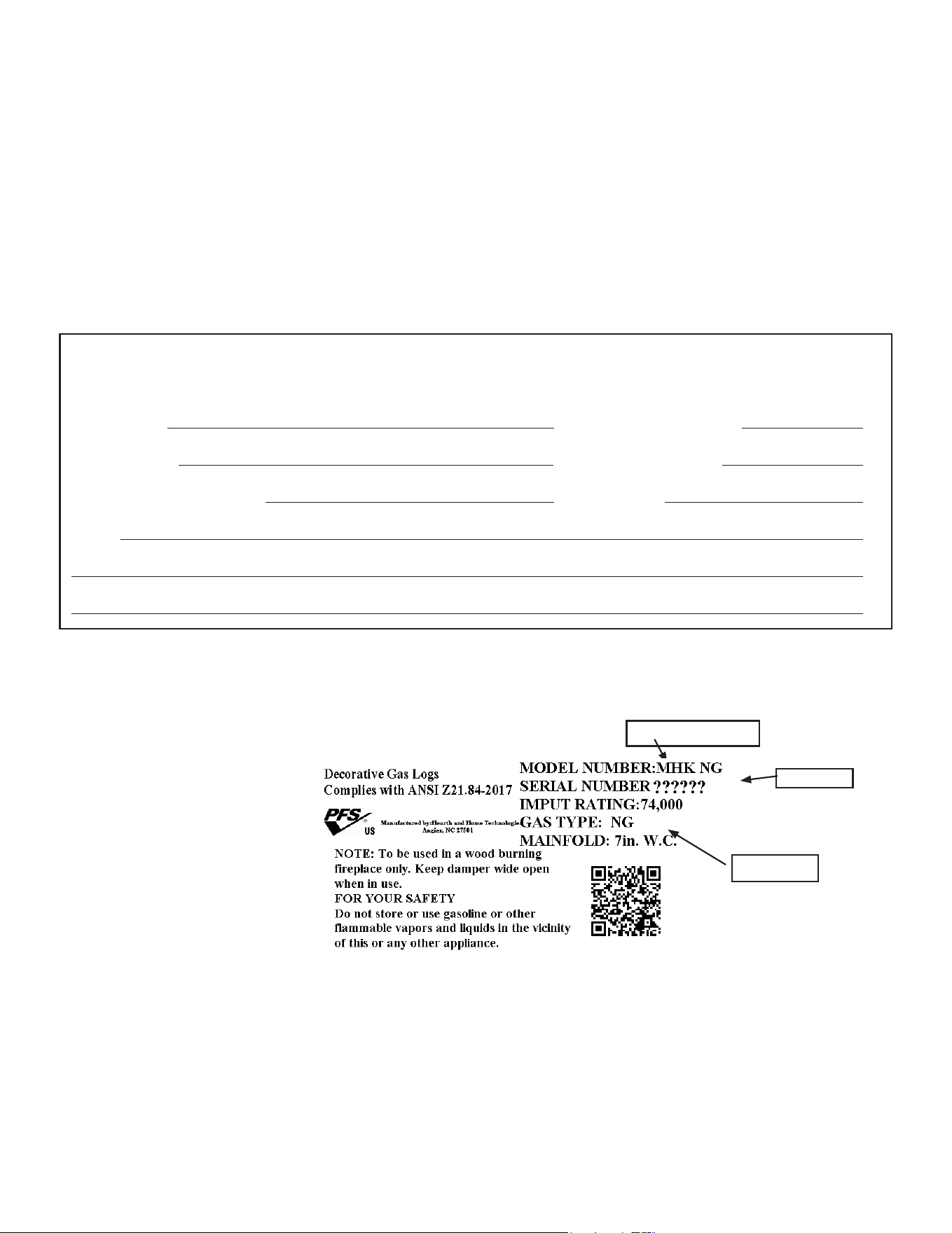
Listing Label Information/Location
e model information regarding your specic gas log set can be found on the rating plate.
Congratulations
Homeowner Reference Information
Model Name: Date purchased/installed:
Serial Number: Location on appliance:
Dealership purchased from: Dealer phone:
Notes:
We recommend that you record the following pertinent
information about your gas log set:
SERIAL #
MODEL NUMBER
GAS TYPE

Hearth & Home Technologies • Fireside Burner/Hearth Kits • 4004-304 Rev J • 01/2022
3
Table of Contents
1 Listing and Code Approvals
A. Appliance Certication. . . . . . . . . . . . . . . . . . . . . . . . . . . . . . . . 4
B. Table 1 ..............................................4
C. Table 2 ............................................. 5
2 Getting Started
A. Size of Firebox .......................................6
B. Negative Pressure ....................................6
C. Tools and Supplies Needed ............................6
D. Inspect the Appliance and Components .................6
E. Components of the Gas Hearth Kit .....................7
3 Appliance Preparation
A. Gas Supply Connection ...............................8
B. Convert to Le Side Gas Piping ........................8
C. Gas Pressure .........................................9
4 Installation Instructions
A. Install the Damper Stop ..............................10
B. Install the Burner/Pan Assembly ......................10
C. Install the Grate .....................................10
D. Place Sand and Rockwool ............................10
E. Install the Logs ......................................11
F. Adjust the Burner Flame .............................11
G. Inspect the Venting System ...........................11
5 Operating Instructions
A. Lighting Instructions ................................12
B. Glass Doors ........................................13
C. Important Safeguards ................................13
6 Maintaining and Servicing the Appliance
A. Servicing Your Appliance .............................14
B. Cleaning Your Appliance .............................14
C. Annual Inspection ................................... 14
D. Troubleshooting. . . . . . . . . . . . . . . . . . . . . . . . . . . . . . . . . . . . . 15
7 Reference Materials
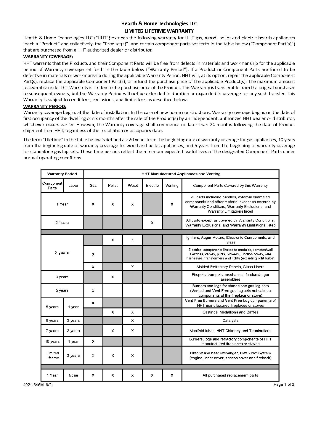
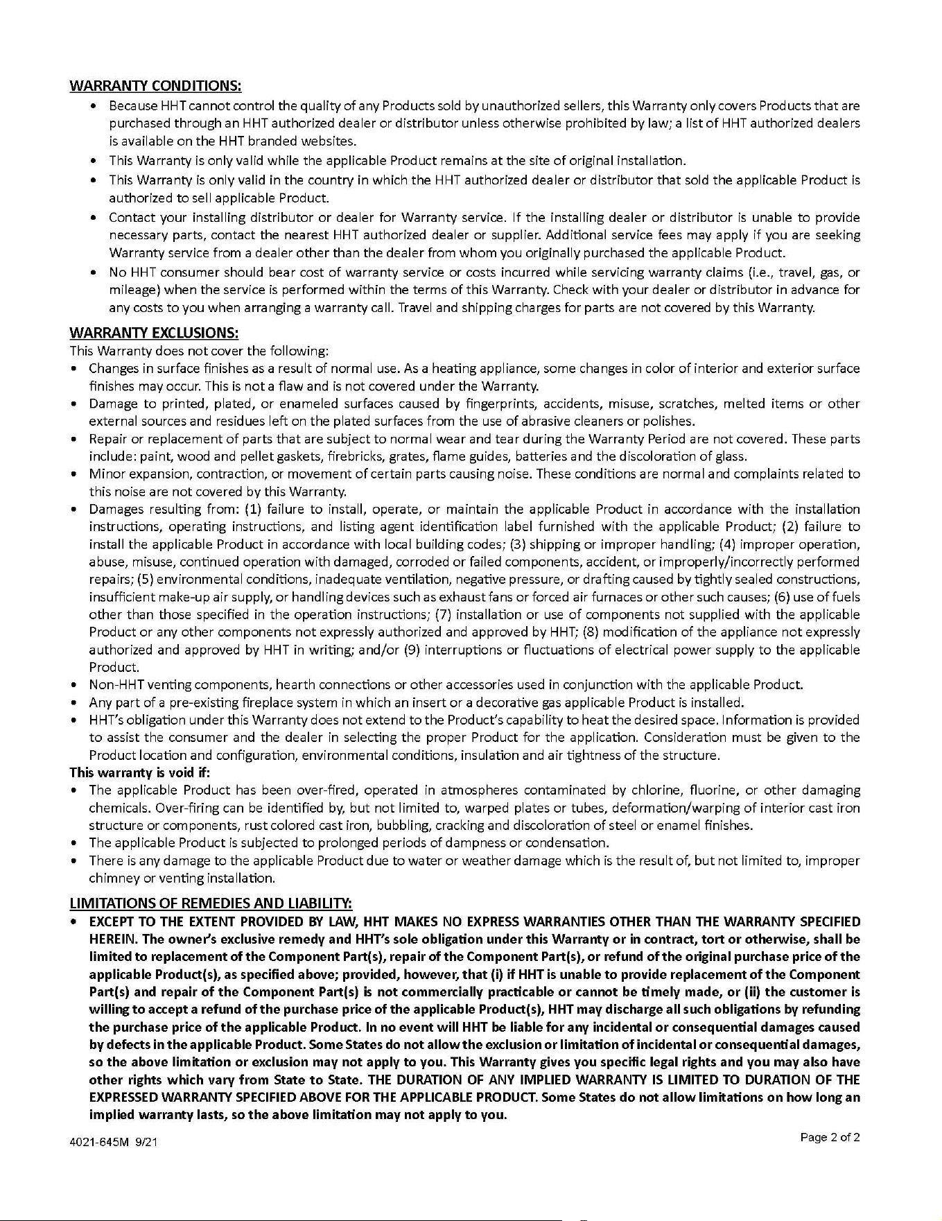
A. Replacement Parts ................................ 16-17
B. Warranty ........................................ 18-19
C. Contact Information ................................. 20
Hearth & Home Technologies • Fireside Burner/Hearth Kits • 4004-304 Rev J• 01/2022
4
11
Listing and Code Approvals
A. Appliance Certication
e Gas Log Hearth Kits have been tested and listed in the U.S. in
accordance with ANSI Z21.84‑2017 (Gas Log Set). ey have
been listed by PFS Test Labs for installation and operation in the
United States and Canada as described in these Installation and
Operating Instructions. All components are UL, OMNI or CSA
safety certied.
Check with your local building code agency prior to installing
this appliance to ensure compliance with local codes, including
the need for permits and follow-up inspections. In the absence of
local codes, comply with the National Fuel Gas Code, ANSI
Z223.1‑Latest Edition in the U.S. If any assistance is required
during installation, please contact your local dealer or call the
Technical Services Department at 1-888-427-3973 or 1-800-927-
6841.
B. Table 1
Product MHK18NG MHK24NG STMHK18NG STMHK24NG
Inlet BTU/KW/HR Nat 74,000/21.7 84,000/24.6 65,000/19 75,000/22
Max. Inlet Pressure
IN. WC/KPa Nat 10.0/.052 10.0/.052 10.0/.052 10.0/.052
Min. Inlet Pressure
WC/KPa Nat 3.5/.018 3.5/.018 3.5/.018 3.5/.018
Or ice S ize
In./mm Nat (#26) .147 (#20) .161 (#30) .128 (#28) .141
Minimum Fireplace Front 28/71.1 34/86.4 28/71.1 34/86.4
Opening S i ze
Rear 16/40.6 18/45.7
In./cm Depth 14/35.6 16/40.6 16/40.6 16/40.6
Height 16/40.6 18/45.7 18/45.7 18/45.7
Weight Pounds 26 31 44 45
Fire Risk
Exhaust Fumes Risk
• Do NOT use this appliance as a “vent-free
heater.
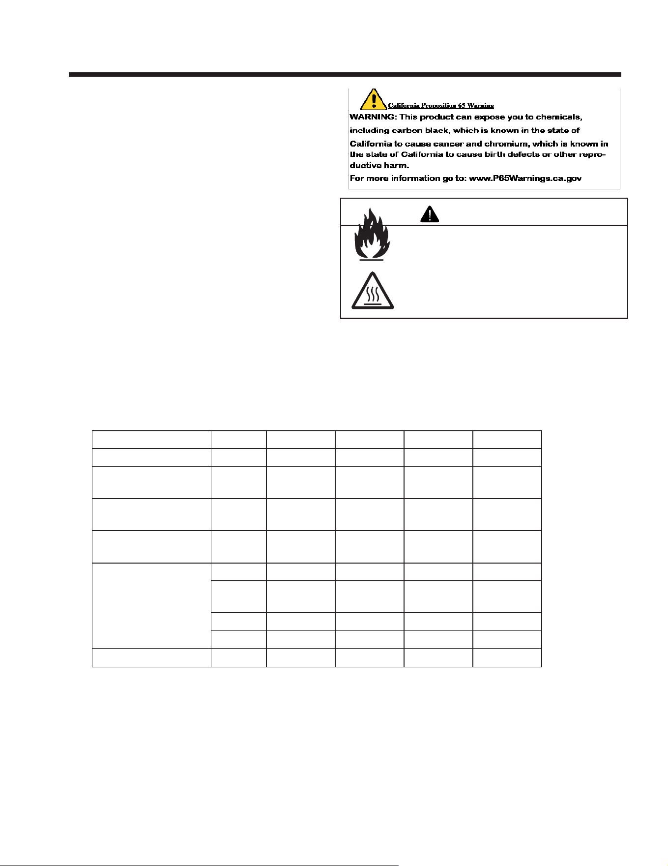
e ue must be permanently open. Refer to
Table 1.
WARNING
Hearth & Home Technologies • Fireside Burner/Hearth Kits • 4004-304 Rev J • 01/2022
5
C. Table 2
Hearth & Home Technologies • Fireside Burner/Hearth Kits • 4004-304 Rev J• 01/2022
6
2 2
Getting Started
A. Size of Firebox
See Table 1 in Section 1.B.
Asphyxiation Risk
is appliance produces carbon monoxide (CO).
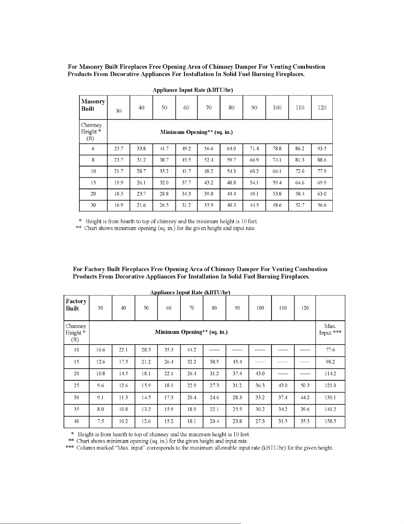
• e free opening areas (in square inches) of
the chimney damper as shown in C. Table 2
must be met.
• User must make sure damper is locked open.
• e installer is responsible to ensure proper
ventilation of ue gases before appliance is
used.
Fire needs to dra properly for safe operation.
WARNING
B. Negative Pressure
Negative pressure results from the imbalance of air available for
the replace to operate properly. Causes for this imbalance include:
• Exhaust fans (kitchen, bath, etc.).
• Range hoods.
• Combustion air requirements for furnaces, water heaters and
other combustion appliances.
• Clothes dryers.
• Location of return-air vents to furnace or air conditioning.
• Imbalances of the HVAC air handling system.
• Upper level air leaks: recessed lighting, attic hatch opening, duct
leaks.
C. Tools and Supplies Needed
Tools and supplies normally required for installation:
Pliers
Phillips screwdriver
Tape measure
Crescent wrenches
Gas shuto valve
Non-corrosive leak check solution
3/4 in. wrench, 7/16 in. wrench
Sharp Edges
• Wear protective gloves
and safety glasses during
installation.
CAUTION
D. Inspect the Appliance and Components
• Remove the contents from the carton. Attached to the burner are
tags identifying the manufacturer name, serial number, model
number (including gas log size), BTU ratings, gas type, etc.
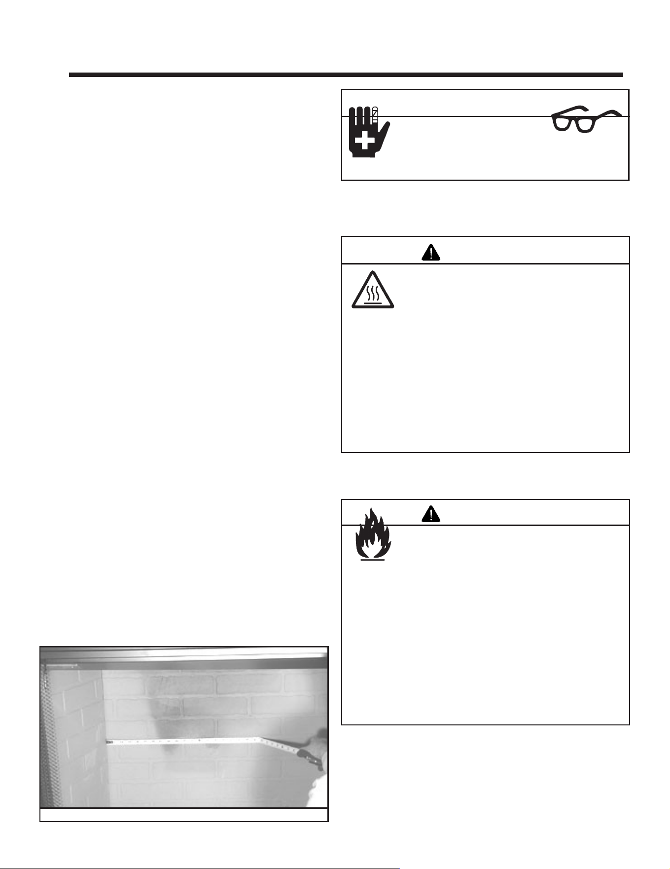
• Review the attached tags before proceeding. Ensure that all
minimum fireplace dimension requirements are achieved
using Table 1 in Section 1.B. See Figure 2.1. Ensure the gas type
provided in the replace coincide with the gas type marked on
the tag.
Figure 2.1 Measure Firebox
Hearth & Home Technologies disclaims any
responsibility for, and the warranty will be voided
by, the following actions:
• Installation and use of any damaged appliance or vent
system component.
• Modication of the appliance or vent system.
• Installation other than as instructed by Hearth & Home
Technologies.
• Improper positioning of the gas logs or the glass door.
• Installation and/or use of any component part not approved
by Hearth & Home Technologies.
Any such action may cause a re hazard.
WARNING
Hearth & Home Technologies • Fireside Burner/Hearth Kits • 4004-304 Rev J • 01/2022
7
E. Components of the Gas Hearth Kit
e Burner/Hearth Kit consists of the following:
• Burner/Pan Assembly
• Grate Assembly
• Glowing Embers
• Sand
• Lava Rock
• Damper Stop
• Aluminum Tubing Assembly
• Brass Elbow Connector
• Brass Orice & Cap
• Log Set (sold separately)
Keep appliance dry.
• Mold or rust may cause odors.
• Water may damage controls.
WARNING
Do NOT use this appliance if any part has been under water.
Immediately call a qualied service technician to inspect the
appliance and to replace any part of the control system and
any gas control which has been under water.
WARNING
Inspect appliance and components for damage.
Damaged parts may impair safe operation.
• Do NOT install damaged components.
• Do NOT install incomplete components.
• Do NOT install substitute components.
Report damaged parts to dealer.
WARNING
Shock Risk
Fire Risk
Use ONLY optional accessories approved for this
appliance.
• Using non-listed accessories voids warranty.
• Using non-listed accessories may result in a
safety hazard.
• Only Hearth & Home Technologies approved
accessories may be used safely.
WARNING
Improper installation, adjustment, alteration, service or
maintenance can cause injury or property damage. Refer to
the owner’s information manual provided with this appliance.
For assistance or additional information consult a qualied
installer, service agency or the gas supplier.
WARNING
Hearth & Home Technologies • Fireside Burner/Hearth Kits • 4004-304 Rev J• 01/2022
8
A. Gas Supply Connection
Ensure ttings are of the appropriate size and type on the gas line
connection. If the tubing has to be cut to length be sure to use the
proper cutting and aring tool. Also, be careful not to crimp the
tubing while bending. If the tubing becomes crimped, do not use
for installation.
Fire Risk
Explosion Risk
Verify inlet pressures.
• High pressure may cause overre condition.
• Low pressure may cause explosion.
Install regulator upstream of valve if line pressure is
greater than 1/2 psig.
WARNING
3 3
Appliance Preparation
B. Convert to Left Side Gas Piping
• Remove the brass elbow from the right side.
• Remove the cap from the le side.
Note: Prior to installing the ttings, use Teon tape or joint
compound on the male threads.
Note: An individual manual shuto valve (not supplied) is
required when installing this appliance. e manual shuto
valve must be located in an easily accessible area, no more than
6 feet from the appliance.
Note: Have the gas supply line installed in accordance with local
building codes, if any. If not, follow ANSI 223.1. Installation
should be done by a qualied installer approved and/or licensed as
required by the locality. (In the Commonwealth of Massachusetts
installation must be performed by a licensed plumber or gas tter.)
Note: A listed (and Commonwealth of Massachusetts approved)
1/2 in. (13 mm) T-handle manual shut-o valve and exible gas
connector are connected to the 1/2 in. (13 mm) control valve inlet.
• If substituting for these components, please consult
local codes for compliance.
WARNING
Gas Leak Risk
• Support control when attaching pipe to
prevent bending gas line.
WARNING
Fire Risk
Explosion Risk
• Gas build-up during line purge may ignite.
• Purge should be performed by qualified
technician.
• Ensure adequate ventilation.
• Ensure there are no ignition sources such as
sparks or open ames.
Fire Risk
Explosion Risk
Personal Injury Risk
An explosion could occur if a connection is made
directly to an unregulated propane (LP) tank.
WARNING
Joint compound or Teon tape must be used on all threaded male
connections to ensure a tight seal.
• Replace the cap on the opposite end of the burner tube.
• Install the brass elbow on the le side of the burner.
Hearth & Home Technologies • Fireside Burner/Hearth Kits • 4004-304 Rev J • 01/2022
9
C. Gas Pressure
Proper input pressures are required for optimum appliance per-
formance. Gas line sizing requirements need to be made following
NFPA51.
Fire Risk
Explosion Risk
High pressure will damage valve.
• Disconnect gas supply piping BEFORE
pressure testing gas line at test pressures above
1/2 psig.
• Close the manual shutoff valve BEFORE
pressure testing gas line at test pressures equal
to or less than 1/2 psig.
WARNING
High Altitude Derate
In the USA, input BTU shall be derated 4% (one orice size)
per 1000 feet for altitudes above 2000 feet. In Canada, input
BTU shall be derated 10% (two orice sizes) at altitudes from
2000-4500 feet.
• Gas Supply Pressure: Minimum inlet gas supply pressure must
be 3.5 in. W.C. for the purpose of input adjustment. Maximum
inlet gas pressure must not exceed 10.0 in. W.C. e gas line
supplying the appliance must be sucient size to furnish the
appropriate supply pressure to the appliance while operating in
the “High” setting. (Minimum line ID of 1/2 in. required if the
line is longer than 20 .
• Gas Line Pressure Test: Perform pressure test according to state
and local code (if pressure exceeds 1/2 in. psi [3.5 kPa]) before
appliance is connected. Be sure to release air pressure from the
gas line before connection is made to the appliance.
• Gas Leak Test: Make sure the gas connections are tight. Turn
on the gas and coat each joint with a non-corrosive gas leak
check solution. Air bubbles will form indicating any leaks. DO
NOT USE A FLAME OR ANY TYPE OF IGNITION SOURCE
TO CHECK FOR LEAKS. All leaks must be corrected before
proceeding with installation.
• e appliance must only be installed in a solid-fuel burning
replace with the ue damper clamped open. e replace
must be constructed of non-combustible material.
• e minimum permanent free opening (in square inches) that
must be provided by the replace chimney or damper to vent the
ue gases is provided in C.Table 2. If the free opening is smaller
than the specied area, do not use this appliance.
• e damper must be removed or xed in a manner in which
will secure it open. Some jurisdictions require the damper to be
removed or permanently welded fully open. Check with state
and local codes.
• Be sure that the chimney is completely unobstructed to ensure
proper ventilation of ue gases including carbon monoxide
(CO). CO (a poisonous gas) is tasteless, odorless, colorless and
undetectable without proper equipment.
WARNING
CHECK FOR GAS LEAKS
Fire Risk
Explosion Risk
Asphyxiation Risk
• Check all ttings and connections.
• Do not use open ame.
• Aer the gas line installation is complete, all
connections must be tightened and checked
for leaks with a commercially available, non-
corrosive leak check solution. Be sure to rinse
o all leak check solution following testing.
Fittings and connections may have loosened
during shipping and handling.
Hearth & Home Technologies • Fireside Burner/Hearth Kits • 4004-304 Rev J• 01/2022
10
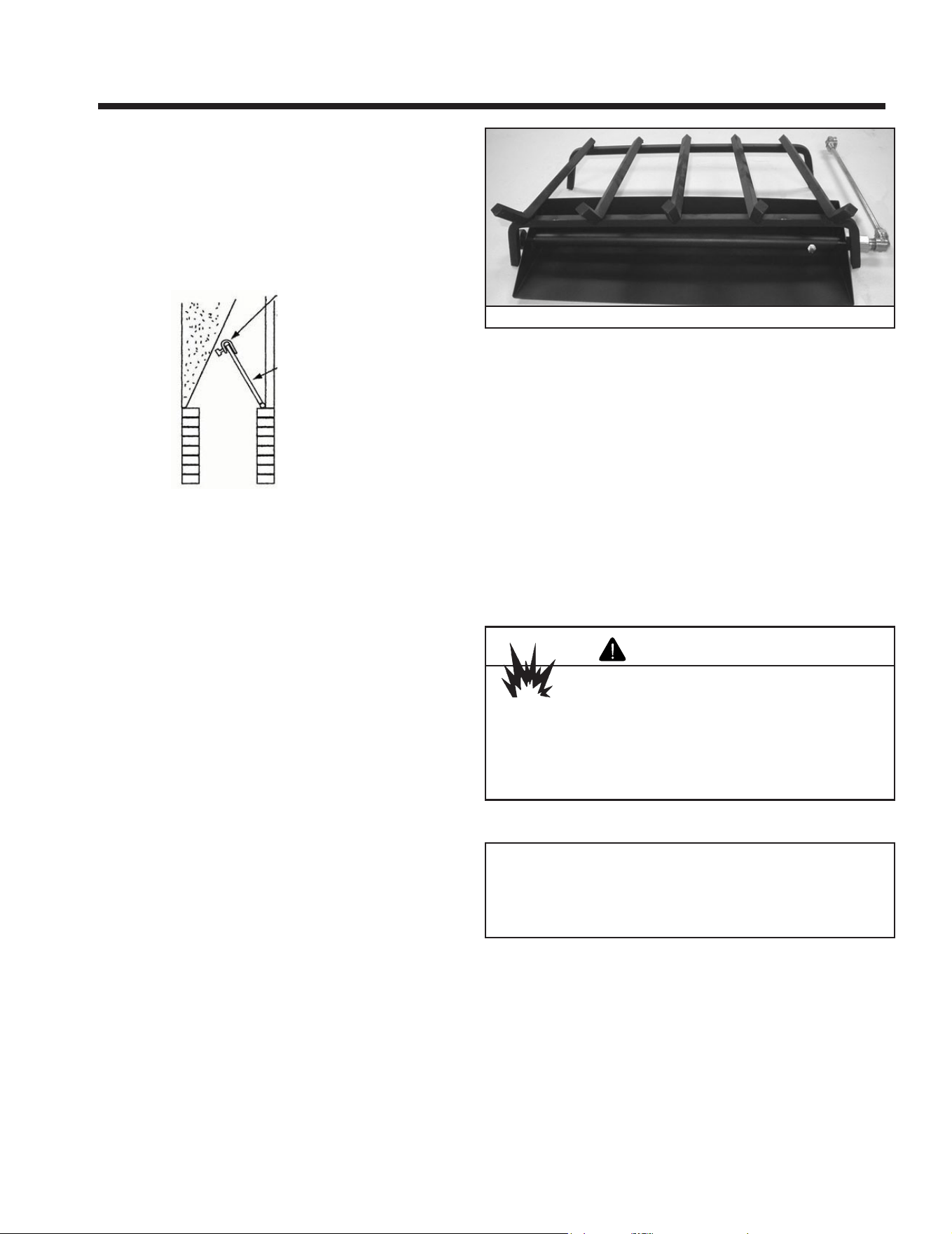
Figure 4.2 Center Grate Over Burner Pan
4 4
Installation Instructions
A. Install the Damper Stop
• Open the damper to the fully open position and secure it open
with the stop as shown in Figure 4.1.
• If the damper stop doesn’t t your application, use a permanent
means that will keep the damper open at least to the minimum
vent opening as outlined in Table 2, Section 1.C.
Figure 4.1 Damper Operation
B. Install the Burner/Pan Assembly
e burner/pan assembly is shipped ready for right-hand gas con-
nection. See Section 3.B. for le-hand connection.
• Remove the existing cap or gas jet assembly from the gas stub in
your replace. Clean the threads using a wire brush or steel wool.
Apply Teon tape or pipe dope to the steel tting and attach the
provided brass adapter to the stub.
• Place the burner/pan assembly in the replace. e pan should
be centered both front to back and side to side.
• Bend the provided gas connector to facilitate its installation
between the burner and the gas stub.
• Attach one end of the gas connector to the brass elbow or safety
pilot tting. Attach the other end to the brass adapter at the gas
tube.
C. Install the Grate
• e grate should be centered over the burner pan, side to side. If
the grate sits toward the front of the burner pan, the ames will
be larger coming through the logs. If the grate sits toward the
back of the burner pan, the ember bed will be more prominent.
Refer to Figure 4.2.
D. Place Sand and Rockwool
• Pour the sand into the burner pan. Sand should follow the slope
of pan, covering it and the burner tube completely.
• Allow the sand to spill out the front of the pan and over the sides
onto the replace oor.
• Lightly place dime-sized pieces of rockwool evenly on top of the
sand or vermiculite.
• e gas burns at the point of the least resistance. In case of an
uneven ame pattern it may be necessary to adjust the materials
in the pans (using an object such as a screwdriver) to achieve
the desired eect.
Explosion Risk
• Follow rockwool placement instructions in
this manual.
• Replace rockwool material annually.
Improperly placed rockwool interferes with
proper burner operation.
WARNING
Note: For best results, do not pack down the rock wool. e
placement of rock wool can have an eect on ame pattern and
may need to be adjusted to achieve a desired appearance.
Hearth & Home Technologies • Fireside Burner/Hearth Kits • 4004-304 Rev J • 01/2022
11
E. Install the Logs F. Adjust the Burner Flame
• e burner ame can be adjusted at the manual shuto valve
beside the replace to obtain the desired ame appearance.
• e ame color will stabilize aer ten minutes of operation.
G. Inspect the Venting System
e replace venting system is designed and constructed to
develop a positive ow adequate to remove ue gases to the outside
atmosphere. See replace installation instructions.
A spillage test must be made before the installed
appliance is left with the consumer
• Close all doors and windows in the home.
• Light the log set.
• Aer three minutes, test with a smoke match, smoke candle, stick
incense or “hand held portable CO detector” one inch below
the top of the opening (lintel) moving across the full width. If
spillage (smoke drawn into the room) occurs, it will most likely
be near the top, outside corners.
Possible Cures if Spilling Occurs
• e damper should be fully open.
• e replace opening needs to be reduced by adding a drop
panel across the top under the lintel.
• e air supply from outdoors needs to be increased. Open the
outside air kit if the appliance is so equipped, or crack open a
door or window.
• If necessary, seek expert advice. Do not operate this appliance.
Cleaning
• Periodic examination and cleaning of the venting system of the
replace should be done before initial use and at least annually
by a qualied agency.
Fire Risk
Explosion Risk
Inspect external vent cap regularly.
• Ensure no debris blocks cap.
• Combustible materials blocking cap may
ignite.
• Restricted air ow aects burner operation.
WARNING
Fire Risk
Explosion Risk
Personal Injury Risk
Failure to position the parts in accordance with
the diagrams provided with the log packages
or failure to use only parts approved with this
appliance may result in property damage or
personal injury.
WARNING
Note: If your log set is the burnt-out type, place the rock wool
in the center of the logs to give a glowing ember eect.
• Install the logs using the installation instructions included with
them.
• Light the burner as outlined in the operating section. Allow
the ame pattern to stabilize. If you are satised with the ame
pattern go to the next step. If you want more or less ame around
the front log, turn o the gas and move the grate backward or
forward.
• Once you are satised, turn on the gas and go on to the next
step.
• Arrange the top logs as shown in your log set up instructions.
Light the burner as outlined in the operating instructions and
allow the ame to stabilize.
• Spread the lava rock around the outside of the burner pan on the
oor of the replace. If possible, cover the gas connector with
the cinders.
Hearth & Home Technologies • Fireside Burner/Hearth Kits • 4004-304 Rev J• 01/2022
12
5 5
Operating Instructions
A. Lighting Instructions
Hearth & Home Technologies • Fireside Burner/Hearth Kits • 4004-304 Rev J • 01/2022
13
B. Glass Doors
If your replace is equipped with glass doors:
• Glass doors should be in fully open poisition when appliance is
operating.
• Operating in the closed position will block the radiant heat
output and may cause incomplete combustion of the gas and
minimize overheating of any valve installation.
C. Important Safeguards
• Other Fuels
- Although your gas log set is very realistic in appearance,
it is not a real woodburning re and must not be used for
burning any fuel other than natural gas.
- To avoid irreparable damage to the appliance and/or personal
injury, wood, matches, paper, garbage or any other material
must not be placed or thrown on top of the logs.
• Appliance Safety
- To avoid personal injury, do not touch hot surfaces when
the appliance is operating.
- Always ensure that the replace screen is closed when the
appliance is operating.
- Close supervision is necessary when the appliance is being
used near children.
• Do not remove any of the attached metal plates, which contain
important safety and operating information.
• Keep the appliance area clear and free of all combustible
materials, gasoline and other ammable vapors and liquids.
• A qualied service technician must perform installation
and repair. e appliance should be inspected and cleaned
annually by a qualified service technician. More frequent
cleaning may be required due to excessive lint, dust, pet hair,
etc. It is imperative that the control compartments, burners and
air passageways are unobstructed during operation.
- Review proper placement of logs, rockwool, lava rock, sand
or vermiculite.
- Ensure there are no gas leaks.
- Ensure the ow of combustion and ventilation air is not
obstructed (front grilles and vent caps).
• Before installing into a solid fuel burning replace, the chimney
and rebox should be inspected and cleaned to remove soot,
creosote, ashes, paint, bird nests etc.
• Annual examination of the chimney must be performed by a
qualied agency to ensure proper ventilation of ue gases created
by this appliance.
• Have the chimney and adjacent structure inspected and cleaned
by qualified professionals. Hearth & Home Technologies
recommends that NFI certied professionals, or technicians
under the direction of certified professionals, conduct a
minimum of an NFPA 211 Level 2 inspection of the chimney.
• Replace component parts of the chimney and fireplace as
specied by the professionals.
• Ensure all joints are properly engaged and the chimmney is
properly secured.
• Do not allow fans to blow directly into the replace. Avoid any
dras that alter burner ame pattern.
• Do not use a blower insert, heat exchanger insert or other
accessories not approved for use with this appliance.
Solid fuels shall not be burned in a replace where a decorative
appliance is installed.
• If glass doors are present, the glass doors must be fully
opened while appliance is in operation.
Do NOT use this appliance if any part has been under water.
Immediately call a qualied service technician to inspect the
appliance and to replace any part of the control system and
any gas control which has been under water.
WARNING
Fire Risk
High Temperatures
Keep combustible household items away from
appliance.
Do NOT obstruct combustion and ventilation air.
• Do NOT place combustible items on top of
or in front of appliance.
• Keep furniture, draperies away from appliance.
WARNING
Fire Risk
Explosion Risk
Do not close the glass doors during appliance
operation.
• Could cause incomplete combustion of the
gas.
WARNING
• Glass doors may be closed when the hearth kit is not being used.
Hearth & Home Technologies • Fireside Burner/Hearth Kits • 4004-304 Rev J• 01/2022
14
6 6
Maintaining and Servicing the Appliance
A. Servicing Your Appliance
B. Cleaning Your Appliance
Your gas logs require little care. Keep the burner assembly, logs and
burner area surrounding the logs clean by vacuuming or brushing
with a dry paint brush at least twice a year.
• e logs become fragile aer burning. Take care in handling.
• Always turn o the gas before cleaning. For relighting, refer to
lighting instructions located in Section 5.A. of these instructions.
• Always keep the appliance clear and free from combustible
materials, gasoline, and other ammable vapors and liquids.
• Never obstruct the ow of combustion and ventilation air. Keep
the front of the appliance clear of all obstacles and materials.
• Leave clearance of at least 36 in. from the front of the replace.
• e air shutter should not be blocked.
• Logs can get very hot. Handle only when they are cool.
CAUTION
Risk of injury or property damage
Before servicing:
• Turn o gas.
• Turn o electricity to appliance.
• Disable remote control, if one is present.
• Ensure appliance is completely cooled.
After Servicing:
• Replace any screen or barrier that was removed.
• Reseal and reinstall any venting removed for servicing.
WARNING
C. Annual Inspection
Annual inspection by qualified technician
recommended.
Check:
• Condition of doors, surrounds and fronts.
• Obstructions of combustion and ventilation air.
• Condition of logs.
• Condition of rebox.
• Gas connections and ttings.
• Obstructions of termination cap.
Clean:
• Glass.
• Logs.
• Burner, burner ports.
Risk of:
• Fire
• Delayed ignition or explosion
• Exposure to combustion fumes
• Odors
WARNING
• Repair and replacement work should be done by a qualied
service technician.
• Always shut o the gas supply and make sure the appliance is
cool before beginning any service operation.
• Always check for gas leaks aer servicing.
• Always check for proper venting.

Hearth & Home Technologies • Fireside Burner/Hearth Kits • 4004-304 Rev J • 01/2022
15
D. Troubleshooting
With proper installation and maintenance, your new decorative
gas appliance should provide years of trouble-free service. If you
do experience a problem, refer to the troubleshooting guide below.
is guide will assist you or a qualied service technician in the
diagnosis of problems and the corrective action to be taken.
Symptons
Possible Causes Corrective Action
1. A match will
not light the
main burner; no
gas to the main
burner
Main gas shuto valve is
closed.
Make sure the shuto valve located
on the incoming gas line is open
There is air in the gas line. Bleed air from the gas line; wait
ve minutes and attempt to relight
the main burner.
No gas supply to the appli-
ance.
Check the plumbing to ensure the
appliance has been hooked up to the
gas supply line.
A blockage is preventing gas
ow.
Inspect the burner orice for ob-
struction. Call a qualied service
technician.
Hearth & Home Technologies • Fireside Burner/Hearth Kits • 4004-304 Rev J• 01/2022
16
Service Parts
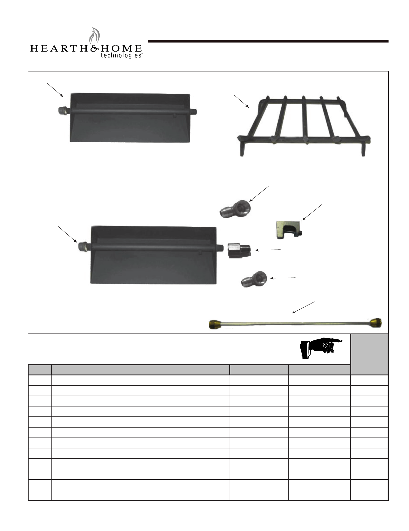
MHK18NG
Beginning Manufacturing Date: Jun 2006
Ending Manufacturing Date: Active
IMPORTANT: THIS IS DATED INFORMATION. When requesting service or replacement
parts for your appliance please provide model number and serial number. All parts listed
in this manual may be ordered from an authorized dealer.
Stocked
at Depot
ITEM DESCRIPTION COMMENTS PART NUMBER
1 Burner Pan Assembly SRVAGLBP14
2 Grate Assembly SRVAG16
3 Orice BPO-2-26
4 Connector Tube SRV3814NXN
5 Damper Stop Assembly SRV500-SC
6 Elbow, 3/8” MFL x 3/8” FPT Brass 01-1050
7 Elbow, 3/8” Flare x 1/2” FIP Brass 10-1037
8 Cap, 1/2” Malleable Pipe 10-1053
Sand SRVACC15
Lava Rock SRVACC10
Glowing Embers SRVACC12
Installation Instructions 4004-304
2/21
18” Hearth Kit
1
2
3
7
6
5
4
8
Hearth & Home Technologies • Fireside Burner/Hearth Kits • 4004-304 Rev J • 01/2022
17
Service Parts
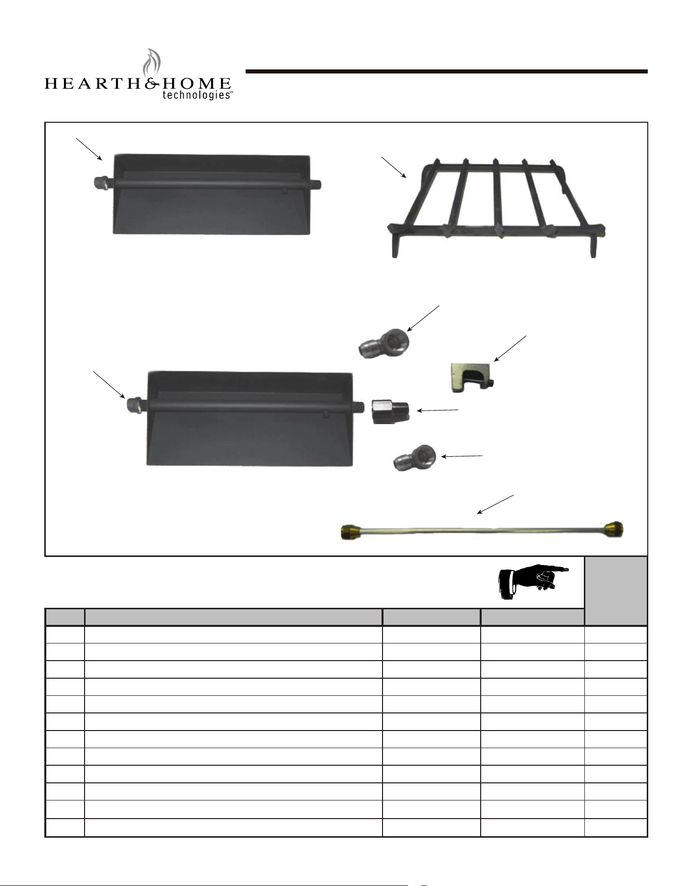
MHK24NG
Beginning Manufacturing Date: Jun 2006
Ending Manufacturing Date: Active
IMPORTANT: THIS IS DATED INFORMATION. When requesting service or replacement
parts for your appliance please provide model number and serial number. All parts listed
in this manual may be ordered from an authorized dealer.
Stocked
at Depot
ITEM DESCRIPTION COMMENTS PART NUMBER
1 Burner Pan Assembly SRVAGLBP18
2 Grate Assembly SRVAG18
3 Orice BPO-2-20
4 Connector Tube SRV3814NXN
5 Damper Stop Assembly SRV500-SC
6 Elbow, 3/8” MFL x 3/8” FPT Brass 01-1050
7 Elbow, 3/8” Flare x 1/2” FIP Brass 10-1037
8 Cap, 1/2” Malleable Pipe 10-1053
Sand SRVACC15
Lava Rock SRVACC10
Glowing Embers SRVACC12
Installation Instructions 4004-304
2/21
24” Hearth Kit
1
2
3
7
6
5
4
8
Hearth & Home Technologies • Fireside Burner/Hearth Kits • 4004-304 Rev J• 01/2022
18
Service Parts
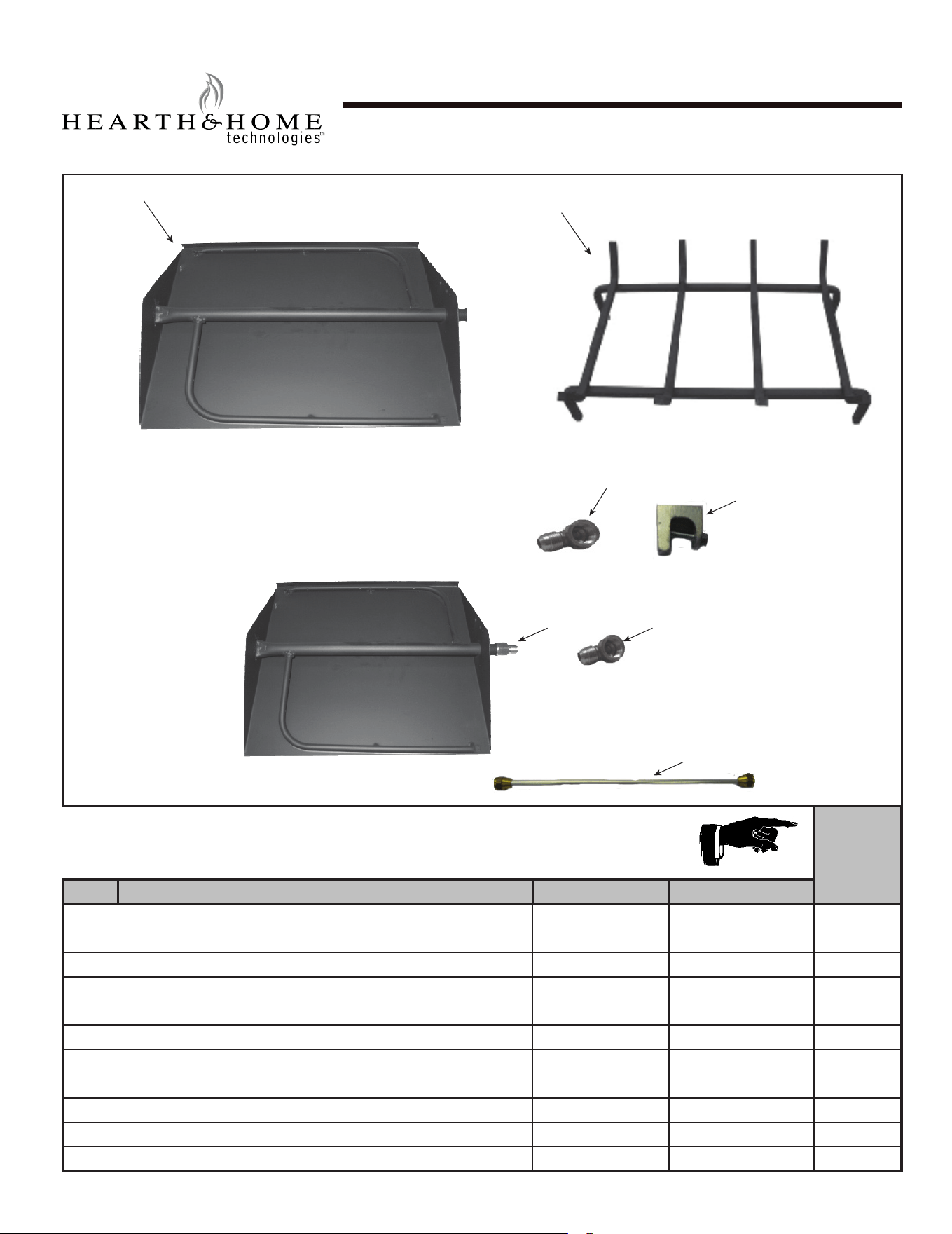
STMHK18NG
Beginning Manufacturing Date: June 2006
Ending Manufacturing Date: Mar 2019
IMPORTANT: THIS IS DATED INFORMATION. When requesting service or replacement
parts for your appliance please provide model number and serial number. All parts listed
in this manual may be ordered from an authorized dealer.
Stocked
at Depot
ITEM DESCRIPTION COMMENTS PART NUMBER
1 Burner Pan Assembly SRVOBP-18ST
2 Grate Assembly SRVAG16
3 Orice BPO-2-26
4 Connector Tube SRV3814NXN
5 Damper Stop Assembly SRV500-SC
6 Elbow, 3/8” MFL x 3/8” FPT Brass 01-1050
7 Elbow, 3/8” Flare x 1/2” FIP Brass 10-1037
Sand Qty. 2 Req. SRVACC15
Lava Rock Qty. 2 Req. SRVACC10
Glowing Embers Qty. 2 Req. SRVACC12
Installation Instructions 4004-304
2/21
18” Matchlight See Thru Hearth Kit
1
2
3
4
5
6
7
Hearth & Home Technologies • Fireside Burner/Hearth Kits • 4004-304 Rev J • 01/2022
19
Service Parts
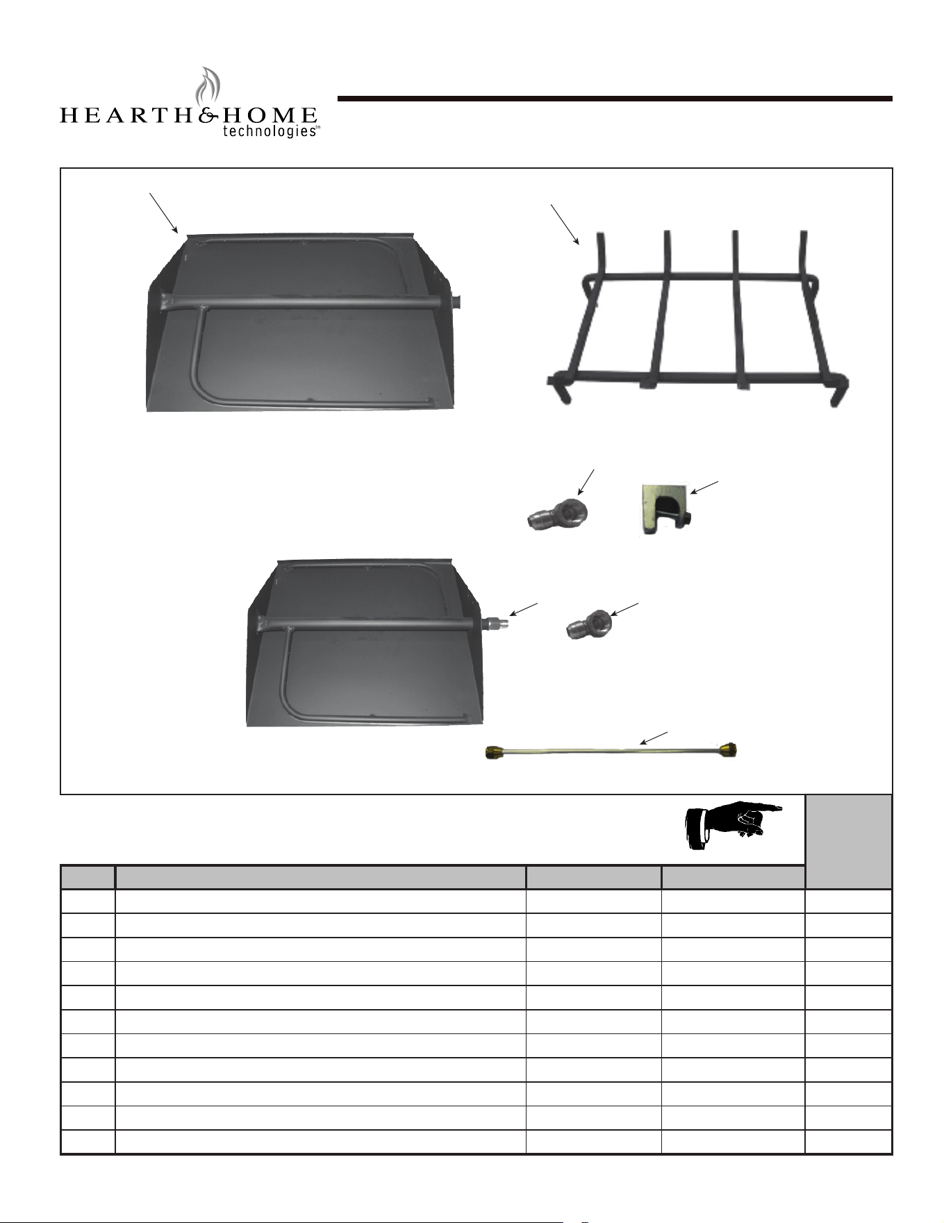
STMHK24NG
Beginning Manufacturing Date: June 2006
Ending Manufacturing Date: Mar 2019
IMPORTANT: THIS IS DATED INFORMATION. When requesting service or replacement
parts for your appliance please provide model number and serial number. All parts listed
in this manual may be ordered from an authorized dealer.
Stocked
at Depot
ITEM DESCRIPTION COMMENTS PART NUMBER
1 Burner Pan Assembly SRVOBP-18ST
2 Grate Assembly SRVAG16
3 Orice BPO-2-26
4 Connector Tube SRV3814NXN
5 Damper Stop Assembly SRV500-SC
6 Elbow, 3/8” MFL x 3/8” FPT Brass 01-1050
7 Elbow, 3/8” Flare x 1/2” FIP Brass 10-1037
Sand Qty. 2 Req. SRVACC15
Lava Rock Qty. 2 Req. SRVACC10
Glowing Embers Qty. 2 Req. SRVACC12
Installation Instructions 4004-304
2/21
24” Matchlight See Thru Hearth Kit
1
2
3
4
5
6
7
Hearth & Home Technologies • Fireside Burner/Hearth Kits • 4004-304 Rev J• 01/2022
20
Hearth & Home Technologies • Fireside Burner/Hearth Kits • 4004-304 Rev J • 01/2022
21
Hearth & Home Technologies • Fireside Burner/Hearth Kits • 4004-304 Rev J• 01/2022
22
C. Contact Information
Please contact your Hearth & Home Technologies dealer with any questions or concerns.
For the number of your nearest Hearth & Home Technologies dealer, please call 1-800-927-6841 or 1-888-427-3973.
- NOTES -
DO NOT DISCARD THIS MANUAL
CAUTION
• Important operating and
maintenance instructions
included.
•
Leave this manual with
party responsible for use
and operation.
•
Read, understand
and follow these
instructions for safe
installation and
operation.
DO NOT
DISCARD
tm
tm