1
Hearth & Home Technologies • PHSI-MCE Instructions • 2560-973 Rev. C • 5/21
Ducted Passive Heat System for Heat Management
Ducted Passive Heat - Side Discharge: PHSI-MCE
Passive Heat Appliance Models: MEZZO36-C / MEZZO48-C Series,
CRAVE4836-C / CRAVE6048-C Series, ECHELON36-C / ECHELON48-C Series
Installation Instructions
Leave this manual with party responsible for use
and operation.
CAUTION! Risk of Cuts, Abrasions or Flying Debris.
Wear protective gloves and safety glasses during instal-
lation. Sheet metal edges are sharp.
DANGER
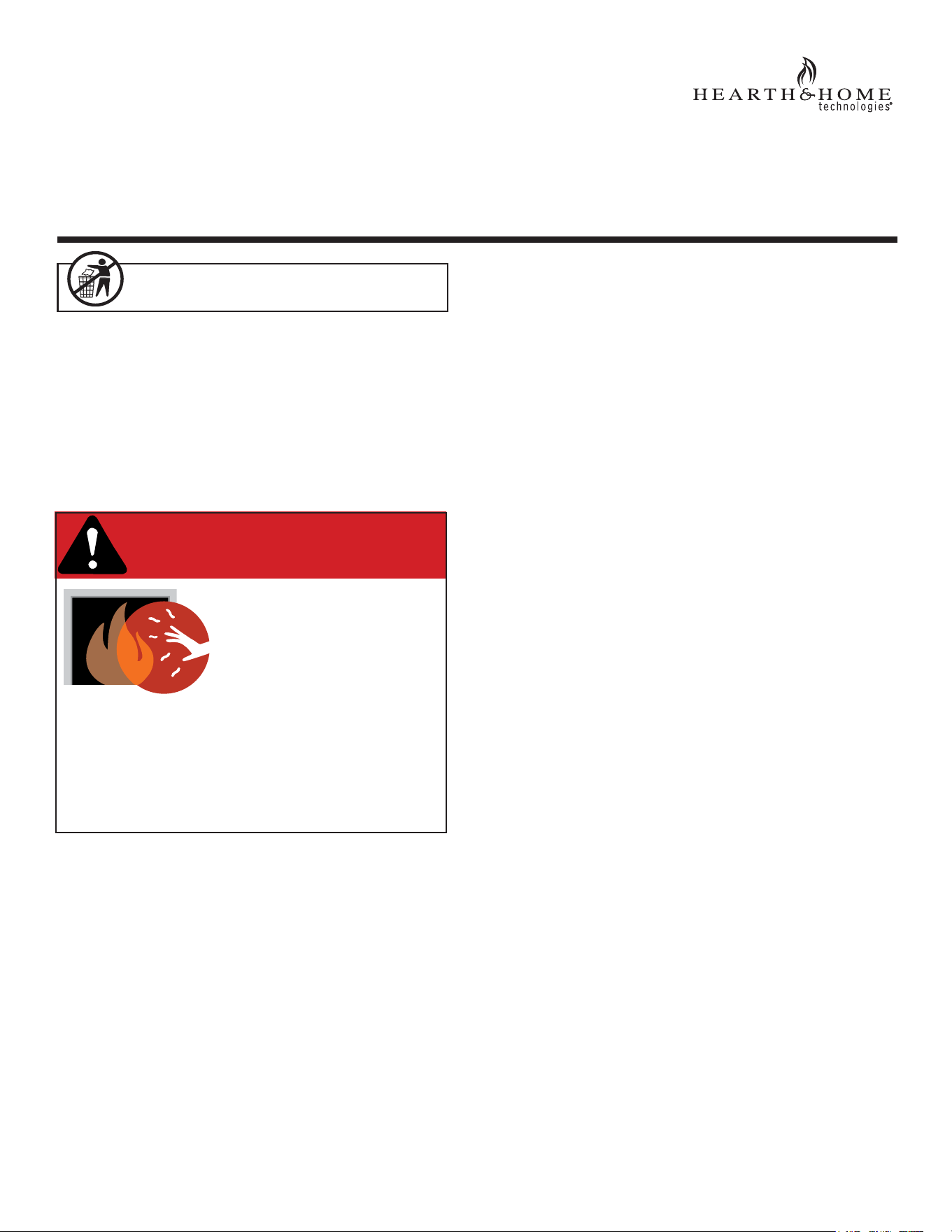
HOT GLASS WILL
CAUSE BURNS.
DO NOT TOUCH GLASS
UNTIL COOLED.
NEVER ALLOW CHILDREN
TO TOUCH GLASS.
A barrier designed to reduce the risk of
burns from the hot viewing glass is provided
with this appliance and must be installed for
the protection of children and other at-risk
individuals.
CAUTION! Do not install damaged components.
WARNING! Risk of Fire!
• Combustible materials MUST NOT overlap or be placed
behind a decorative front.
• DO NOT apply combustible materials beyond the
minimum clearances. Comply with all minimum
clearances to combustibles as specied. Overlapping
materials could ignite and will interfere with proper
operation of decorative fronts.
If any parts are missing or damaged, contact your dealer before
starting installation. DO NOT install a damaged kit.
Table of Contents
1. Introduction .....................................1
2. Kit Contents ....................................2
3. Preparation ..................................... 3
4. Framing (2 X 4 Studs) ............................5
5. Installation Instructions ............................ 6
6. Finishing Instructions - Side Discharge ............. 11
1. Introduction
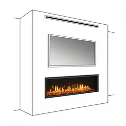
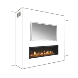
The Side Discharge Ducted Passive Heat (PHSI-MCE)
System conveys warm air from the replace into the same
room through a front discharge slot connected to the ap-
pliance heat management knock outs with the provided
ex ducting. Installation of the Ducted Passive Heat kit
must be done in conjunction with the appliance installation.
Installation of this kit MUST be performed by a qualied
service technician.
WARNING! Risk of Fire! DO NOT install the Ducted
Passive Heat (PHSI-MCE) Heat Management System
with models that are not approved. Overheating will occur.
The Side Discharge Passive Heat Kit is not approved for
use on 60 or 72 sized appliances.
The Ducted Passive Heat kit is tested and safe when
installed in accordance with this installation manual. It is
your responsibility to read all instructions before starting
installation and to follow these instructions carefully during
installation.
The Ducted Passive Heat kit is carefully engineered and
must be installed only as specied. If you modify it or any
of its components you will void the warranty, and you may
possibly cause a re hazard. Installation must be done
according to applicable local, state, provincial, and/or
national codes.
2
Hearth & Home Technologies • PHSI-MCE Instructions • 2560-973 Rev. C • 5/21
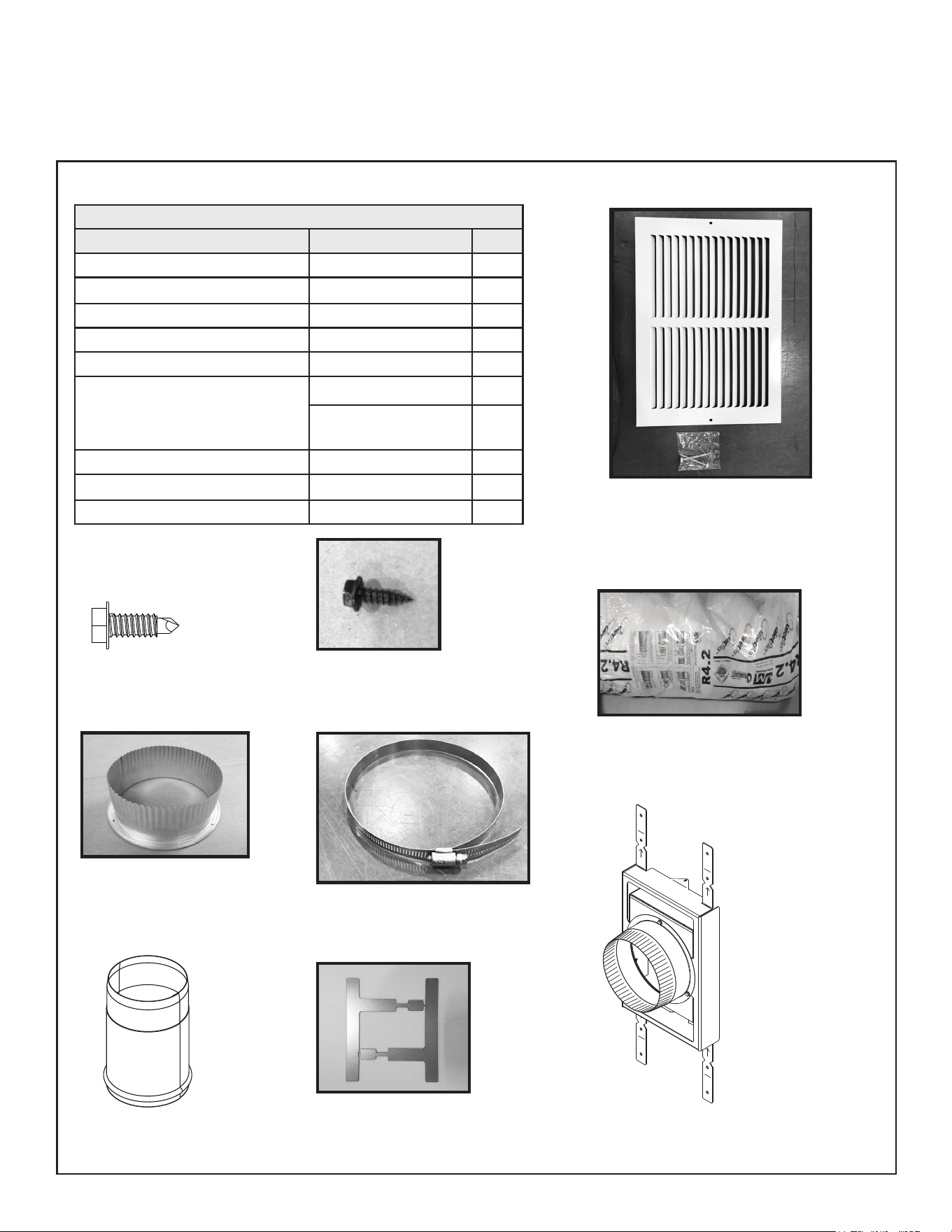
Figure 2.1 Front Discharge Passive Heat Kit Components
659-200
6 Inch Round Duct
SRV659-125 Collar
SRV662-803
Gear Clamp: Large
2005-861
Hurricane Screw
Contents of Ducted Side Discharge Passive Heat Kit (PHSI-MCE)
2. Kit Contents
Verify and remove contents from packaging before
beginning installation. See Figure 2.1.
Self-Tapping #8 Screw
2600-200 Pull Tool
(1 Set)
Inner Flue, Top
Note: The exible duct used with the Ducted Passive Heat
is manufactured and marked to the requirements of UL-
181, Class I air duct.
SIDE DISCHARGE / OPEN TOP DISCHARGE KITS (PHSI-MCE)
DESCRIPTION SERVICE PART NO. QTY
12 in. X 8 in. Register Cover 2560-120 2
Side Discharge Assembly 2560-015 2
Collar SRV659-125 2
Flex Air Duct (6” Diameter x 25 ft.) 659-200 1
Gear Clamp: Large SRV662-803 4
Hurricane Screw
2005-861 8
Replacement part:
2005-861/25
1
Pull Tool 2600-200 1 Set
Inner Flue, Top Service part not available 2
Self-Tapping #8 Screw Service part not available 4
2560-120
12 in. x 8 in. Register Cover
(Screws Included)
2560-015
Side Discharge Assembly
3
Hearth & Home Technologies • PHSI-MCE Instructions • 2560-973 Rev. C • 5/21
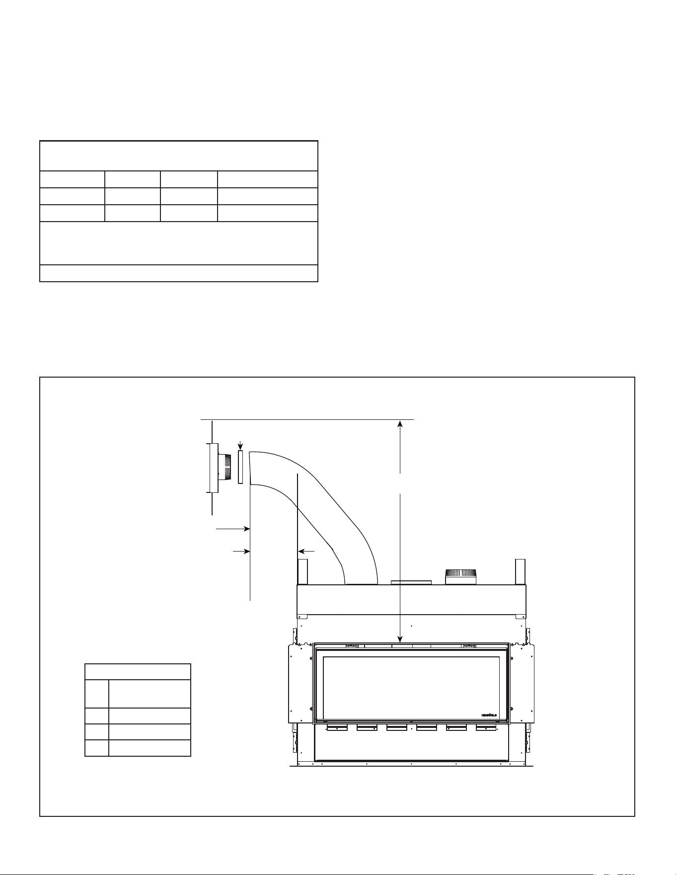
Table 3.1 Air Duct Length & Clearances
Figure 3.1 Side Discharge - Maintain Pitch
3. Preparation
Plan the location of the appliance and the warm air duct
runs. See Table 3.1.
WARNING! Risk of Fire! DO NOT fold/kink/pinch/ob-
struct 6 inch exible ducts. Appliance could overheat.
Things to consider:
Electrical Wiring:
It is recommended to maintain wire routing inside the stud
pockets to reduce temperatures and visibility of wires.
Construction Materials:
It is recommended to plan ahead to reduce the amount of
exposed nishing materials visible through the openings.
PITCH (In Inches)
X
Y Min.PRIMO60
PRIMO60ST
0 52
12 64
24 76
If alternate heat management systems are used with the
Ducted Passive Heat Kit (PHFR-MCE-XX), they must use
an outside heat management knockout location on the far
left or right of the appliance.
AIR DUCT LENGTH
(Measurements in Inches)
SIZE MIN. MAX.* DUCT Quantity
36 28 150 2
48 28 150 2
*This is the maximum vent run length possible with
the included ex duct. Additional ex duct required
for longer vent runs. Contact dealer to order.
PHSI-MCE is not approved for 60 and 72 inch models.
PHSI-MCE
Y
24 IN. MAX.
HORIZONTAL
MAINTAIN
MINIMUM
12/12 PITCH
HOSE CLAMP
X
TOP OF SIDE DISCHARGE ASSEMBLY
4
Hearth & Home Technologies • PHSI-MCE Instructions • 2560-973 Rev. C • 5/21
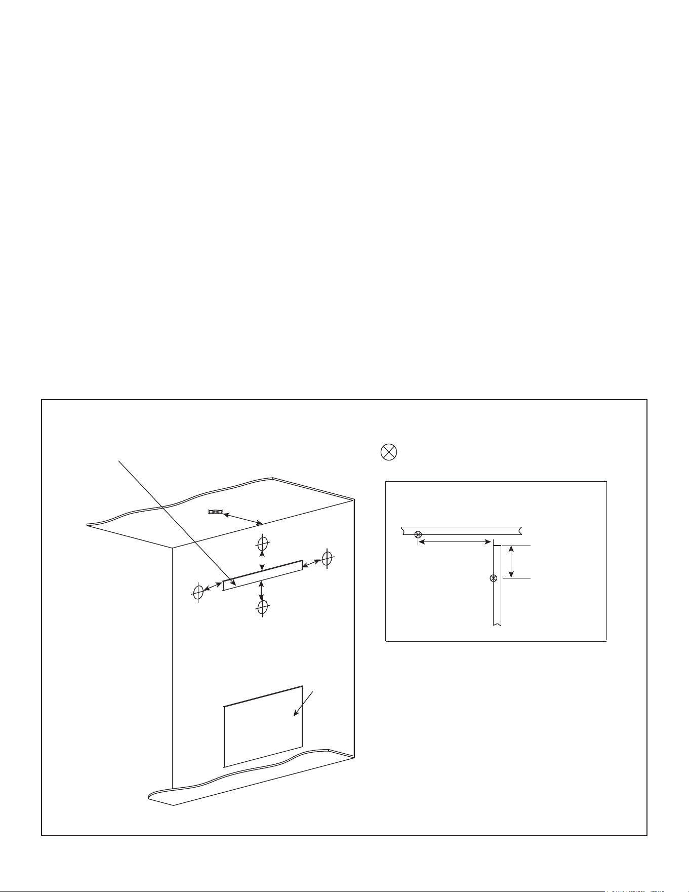
Clearance - Sprinkler to Passive Heat
Figure 3.2 references the clearances that must be ad-
hered to when installing a sprinkler head near a passive
heat discharge opening.
* If the distance from the top of the passive heat
front discharge opening to the ceiling is 36 inches
or greater, then there is no 36 inch clearance
requirement. This is for a ceiling sprinkler head
installation only.
Note: When installing a sprinkler head near a heat
discharge opening, it is recommended to use
a sprinkler head with an Extra High sprinkler
activation temperature rating.
• When installing a sprinkler head exterior of the chase,
maintain the following clearances to discharge openings
(convection slots, passive heat registers, heat zone
registers, etc.): 36 inches top, 18 inches sides and 6
inches bottom.
• DO NOT install a sprinkler head inside a chase that is
set up for passive heat.
INTERIOR WALL
FLOOR
CEILING
36 IN.
36 IN.
6 IN.
18 IN.
18 IN.
PASSIVE HEAT FRONT DISCHARGE OPENING
(Clearances for front and side discharge installations)
FIREPLACE
*
CEILING
INTERIOR WALL
6 IN.
36 IN.
= SPRINKLER HEAD
PASSIVE HEAT OPEN TOP DISCHARGE OPENING
Figure 3.2 Sprinkler Head Clearance
5
Hearth & Home Technologies • PHSI-MCE Instructions • 2560-973 Rev. C • 5/21
4. Framing (2 X 4 Studs)
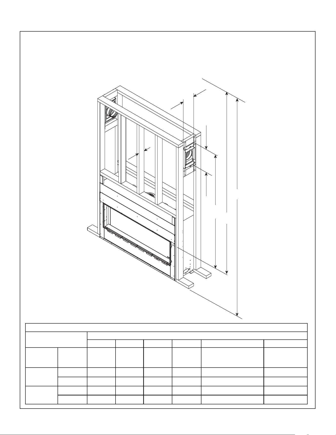
Figure 4.1 Clearances to Combustibles - Passive Heat Side Discharge
Ducted Passive Heat Side Discharge (PHSI-MCE)
Single-Sided or See-Through
Clearances to Combustibles
MINIMUM FRAMING DIMENSIONS
SIDE DISCHARGE
A B C D E F
MODEL
SIZE
Height of
Discharge
Opening
Width of
Discharge
Opening
Clearance
Opening to
Framing
Clearance
Opening to
Ceiling
Clearance
Bottom of Appliance
to Ceiling
2 X 4 Studs
36
Inches 16 10-3/16 50 52 76-1/2 3-1/2
millimeters 406 259 1270 1321 1943 89
48
Inches 16 10-3/16 50 52 76-1/2 3-1/2
millimeters 406 259 1270 1321 1943 89
C
B
A
D
E
F
WARNING! Risk of Fire! DO NOT allow any combustible or non-combustible objects or materials to be placed
where the disruption of airow in discharge zone could occur. Appliance and combustible materials will overheat.
6
Hearth & Home Technologies • PHSI-MCE Instructions • 2560-973 Rev. C • 5/21
5. Installation Instructions
PHSI-MCE kits must be installed on the two inside
passive heat knockouts unless a HEAT-OUT-GAS or
HEAT-ZONE-GAS will also be installed. Outer knockouts
may be used for additional heat management systems
(HEAT-OUT-GAS, HEAT-ZONE-GAS). Do not remove
the outer knockouts if they will not be used.
Only one passive heat option may be installed on a single
appliance. Passive Heat kits without ducts may not be
used in conjunction with the Ducted Passive Heat kit.
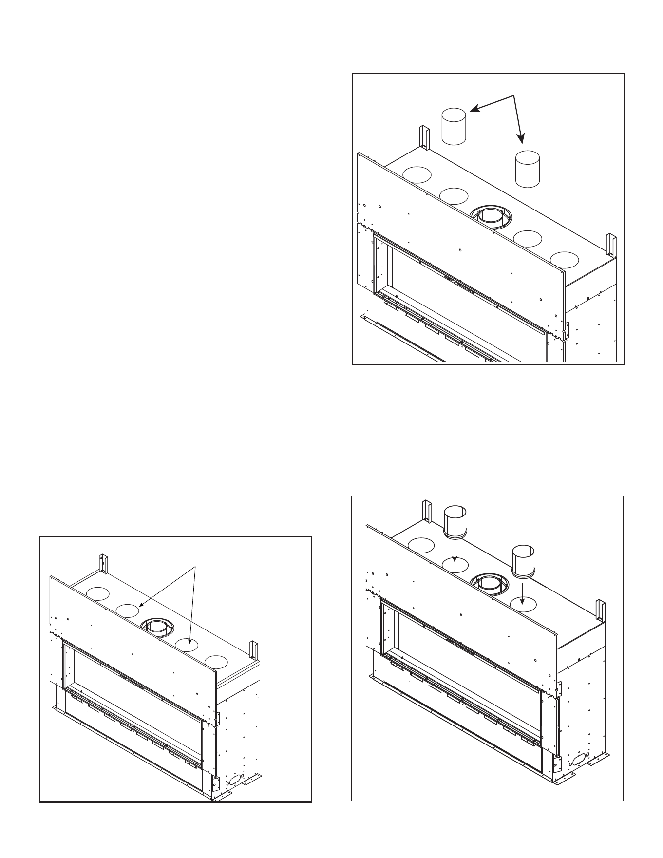
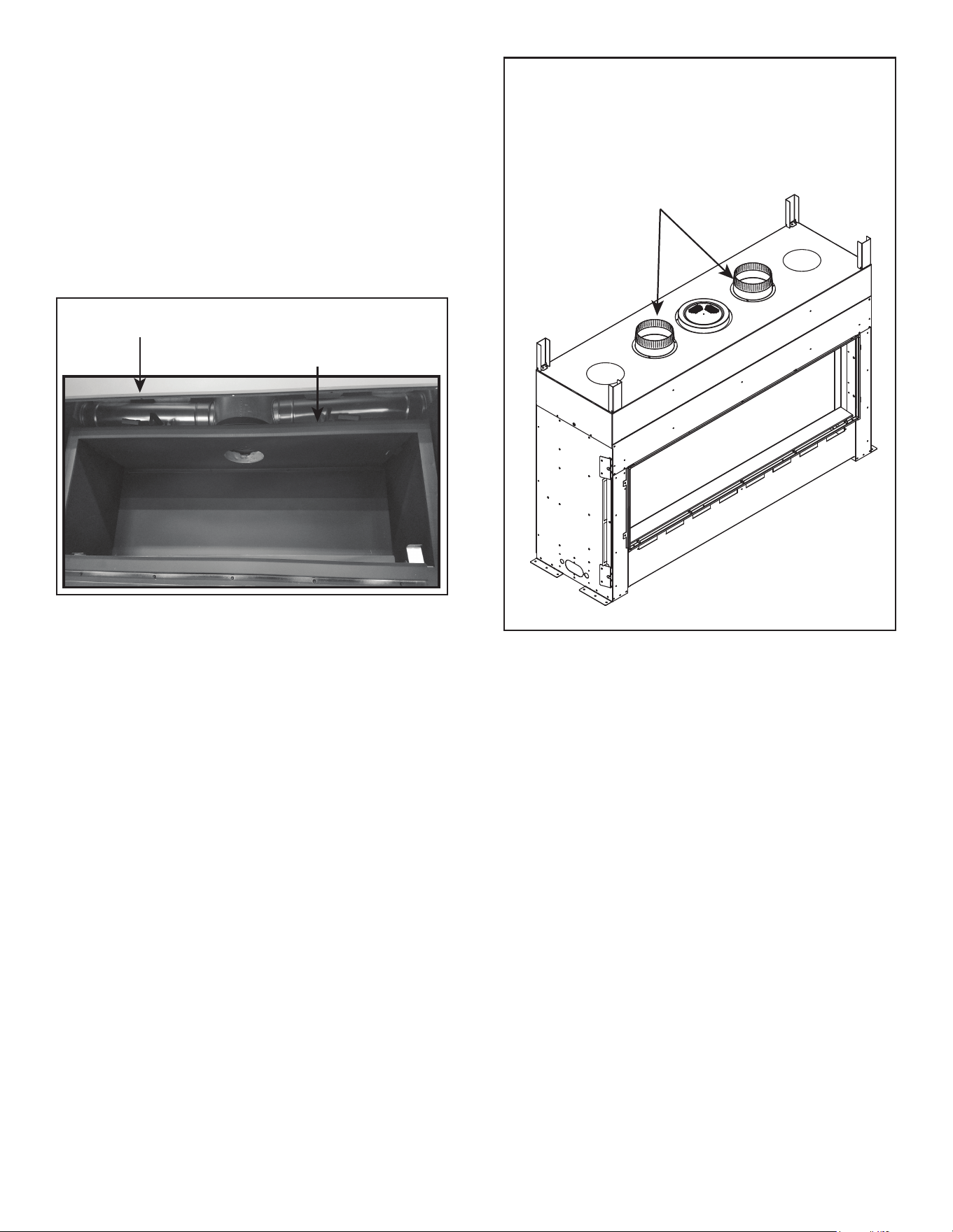
1. Remove the two inner heat management knockouts
from the top of the appliance by dislodging them with
a hammer and then using a screwdriver to remove
from the holes. See Figure 5.1 and Figure 5.2. Install
collars over the openings using hurricane screws
provided in the kit.
WARNING! Risk of Overheating! Both passive heat
side discharge assemblies included with kit MUST be
installed and operational. Overheating of appliance and
combustible materials will occur.
Install Assemblies and Flexible Duct - Side Discharge
CAUTION! Risk of Cuts, Abrasions or Flying Debris.
Wear protective gloves and safety glasses during
installation. Sheet metal edges are sharp.
WARNING! Risk of Fire! Remove ONLY the knockouts
required for the specic heat management kits being
installed. Appliance and combustible materials will
overheat.
REMOVE ONLY TWO INNER KNOCKOUTS
Figure 5.1 Remove Knockouts
3. Set a collar in each of the holes where the knockouts
were removed. See Figure 5.3.
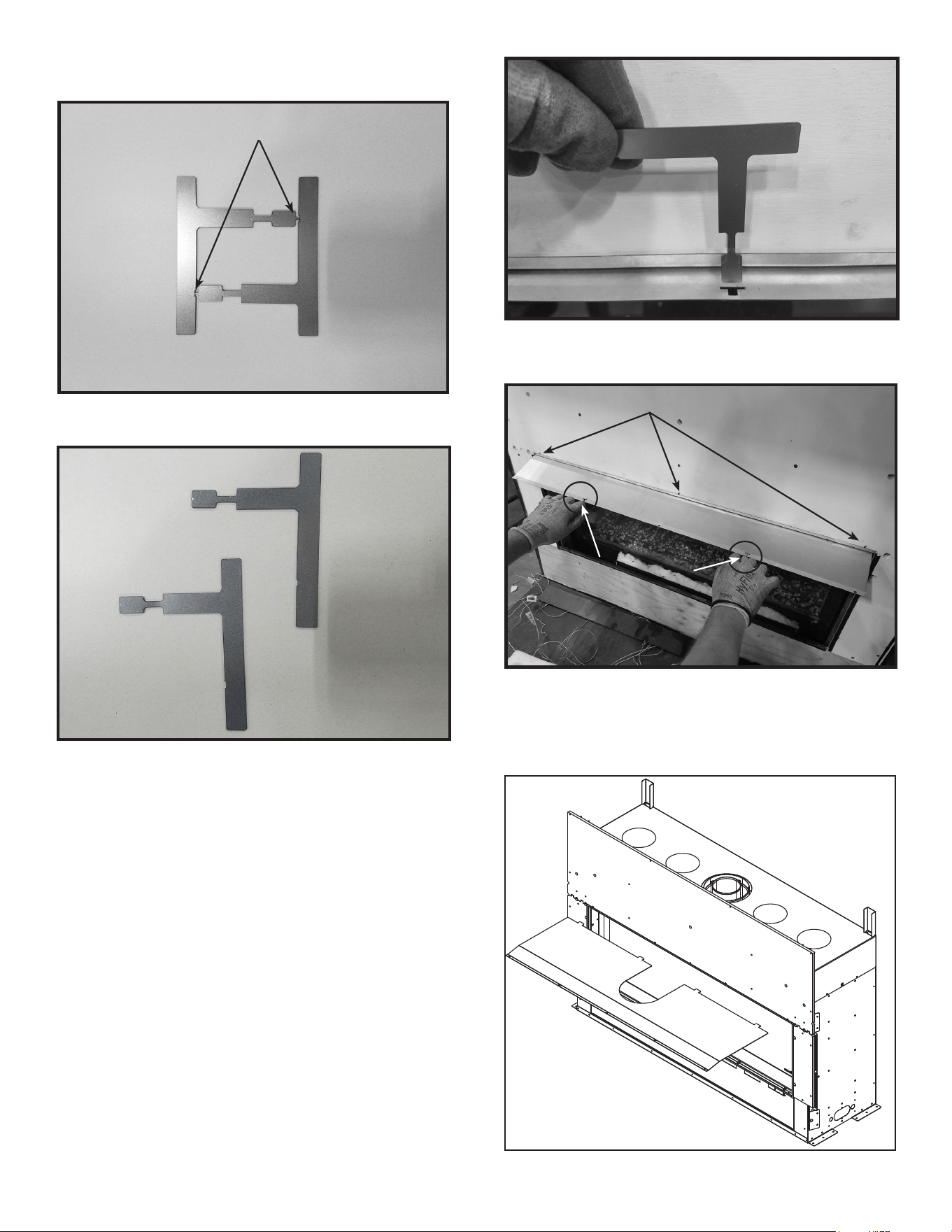
4. Remove the screws from the heat shield as shown in
Figure 5.7. Quantity and location of screws will vary
between models.
REMOVE INSULATION PLUGS
Figure 5.2 Remove Insulation Plugs
Figure 5.3 Install Inner Flues
2. Remove the insulation plug from each knockout.
Discard. See Figure 9.
7
Hearth & Home Technologies • PHSI-MCE Instructions • 2560-973 Rev. C • 5/21
Figure 5.2 Remove Insulation Plugs
6. Insert pull tool into slots on left and right sides of
appliance. See Figure 5.6.
7. Carefully pull the heat shield out of the appliance as
shown in Figure 5.7 and Figure 5.8. Discard heat
shield. Repeat procedure on other side if application
is on a see-through appliance.
Figure 5.7 Use Pull Tools to Remove Heat Shield
Figure 5.5 Pull Tools Separated
Figure 5.6 Pull Tool Inserted Into Slot
REMOVE SCREWSREMOVE SCREWS
PULL TOOLSPULL TOOLS
Figure 5.8 Remove Heat Shield
5. Bend pull tools and break apart as shown in Figure
5.4 and Figure 5.5.
BREAK HEREBREAK HERE
Figure 5.4 Bend and Break Pull Tools Apart
8
Hearth & Home Technologies • PHSI-MCE Instructions • 2560-973 Rev. C • 5/21
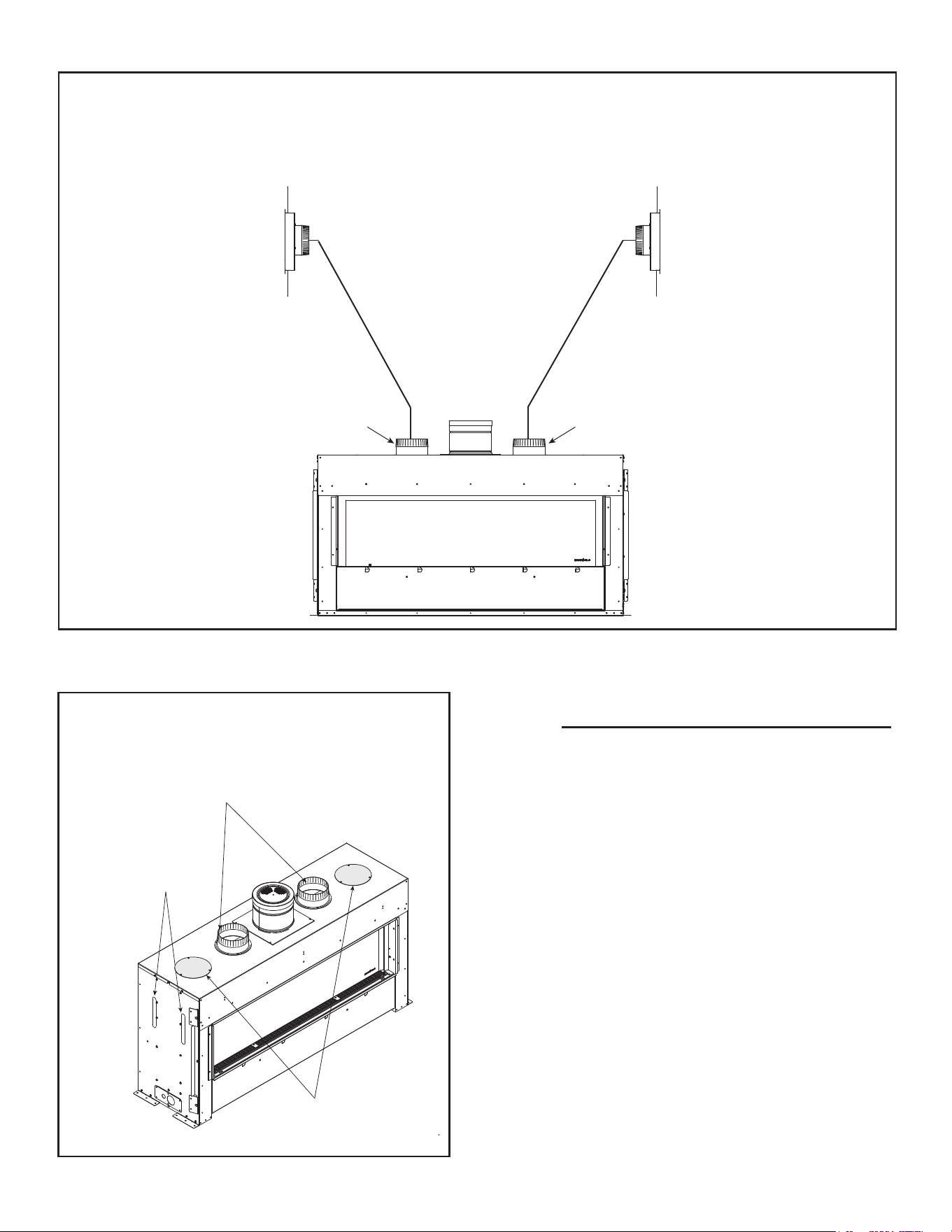
9. Install collars over the openings using hurricane
screws provided in the kit. PHSI-MCE kits must be
installed on the two inside passive heat knockouts.
See Figure 5.10 and Figure 5.11.
WARNING! Risk of Fire! Remove all debris and objects
from rebox top and appliance top before operating the
appliance.
8. Inspect for and remove all debris that may have
accumulated or objects that may have been placed on
the rebox top and appliance top during the installation
process. All debris and objects must be removed
prior to operation of the appliance. Firebox top and
appliance top are shown in Figure 5.9.
Figure 5.9
APPLIANCE TOP
FIREBOX TOP
Figure 5.10 Remove Passive Heat Knockouts
WARNING! Risk of Fire! DO NOT remove appliance
heat management knock-outs unless an approved
heat management system is installed. Appliance and
combustible materials will overheat.
COLLAR LOCATIONS
9
Hearth & Home Technologies • PHSI-MCE Instructions • 2560-973 Rev. C • 5/21
WARNING! Risk of Fire! DO NOT remove unused
outer heat management knock-outs. Overheating
of appliance and combustible materials will occur.
Figure 5.12 Install Collars Over Heat Management Openings
DO NOT
REMOVE
KNOCKOUTS
PASSIVE HEAT COLLARS TO BE LOCATED
ON THE TWO INSIDE HEAT MANAGEMENT
KNOCK-OUTS.
HEAT MANAGEMENT KNOCK-OUTS
AVAILABLE FOR HEAT-OUT-GAS OR
HEAT-ZONE-GAS
Figure 5.11 Ducted Passive Heat - Side Discharge Conguration / Remove Heat Management Knockouts.
Collar
SIDE DISCHARGE ASSEMBLY
SIDE DISCHARGE ASSEMBLY
*Only one passive heat option may be installed on a single appliance.
Ductless passive heat kits may not be used in conjuction with the ducted passive heat kits.
One outside heat management knockout may be used for alternate heat management
(HEAT-ZONE-GAS, HEAT-OUT-GAS)
Collar
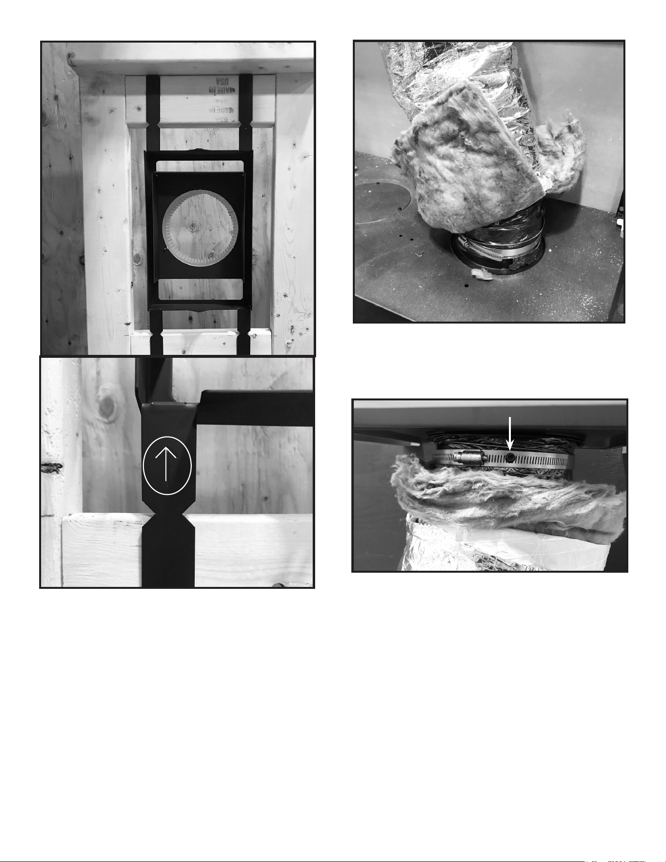
2. Place the side discharge assembly into the wall with
the arrows on the nailing tabs facing upward.
See Figure 5.13. The height of the side discharge
assembly is denoted by the notches in the nailing tabs
that are to be lined up with the edge of the header
closest to the side discharge assembly. Ensure
the side discharge assembly is centered in the wall.
Mount side discharge assemblies into wall using
drywall framing screws or nails.
3. Repeat Step 2 to install the second side discharge
assembly on the other side of the appliance.
10
Hearth & Home Technologies • PHSI-MCE Instructions • 2560-973 Rev. C • 5/21
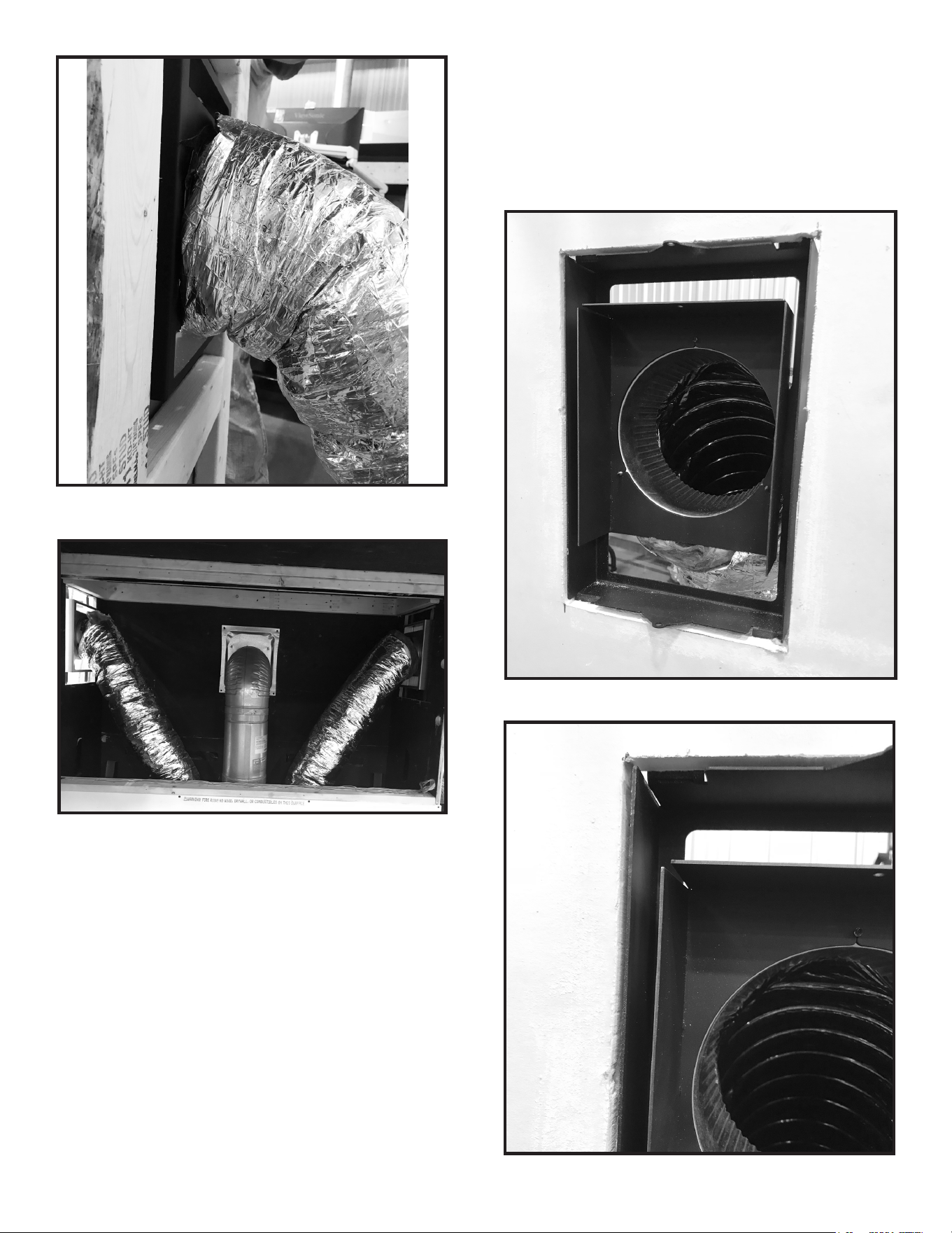
4. Cut ex venting to appropriate length to run from
top of the appliance to the back side of the side dis-
charge assembly ensuring there are not any kinks.
Be sure that the ex venting is not so tight as to col-
lapse where attached to the side discharge assembly
and restrict airow. Refer to Section 3 and Figure 3.1
regarding length and pitch requirements.
Figure 5.14 Install Flex Venting to Appliance
WARNING! Risk of Fire! DO NOT fold/kink/pinch/ob-
struct 6 inch exible ducts. Overheating of appliance and
combustible materials will occur.
NAILING TAB
ARROW UP
Figure 5.13 Side Discharge Assembly Nailing Tab Orientation
5. Secure the ex venting to the collars on both the
appliance and the bottom of the side discharge
assembly using the provided gear clamps. See Figure
5.14-5.17.
DISCHARGE ASSEMBLY
CENTERED IN FRAMING
6. Install self-tapping screw through gear clamp into
collar. Repeat for all collars. See Figure 5.15.
Figure 5.15 Install Screw into Collar
SCREWSCREW
11
Hearth & Home Technologies • PHSI-MCE Instructions • 2560-973 Rev. C • 5/21
6. Finishing Instructions - Side Discharge
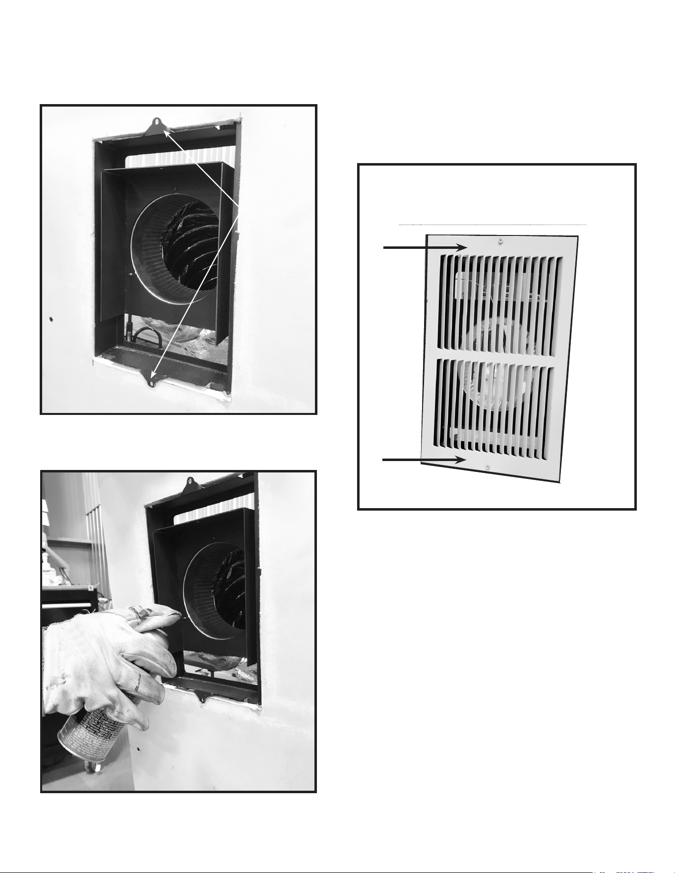
1. Apply wall sheathing material, such as drywall, up
to 1/2 inch thick up to the edge of the installed side
discharge assembly. See Figure 6.1 and Figure 6.2.
Figure 6.2 Finishing Edge
Figure 6.1 Wall Sheathing Installed
WARNING! Risk of Overheating! DO NOT apply wall
sheathing past outside edge of plenum. Overheating of
appliance and combustible materials will occur.
Figure 5.16 Install Flex Venting to Side Discharge Assembly
Figure 5.17 Flex Venting Installed
12
Hearth & Home Technologies • PHSI-MCE Instructions • 2560-973 Rev. C • 5/21
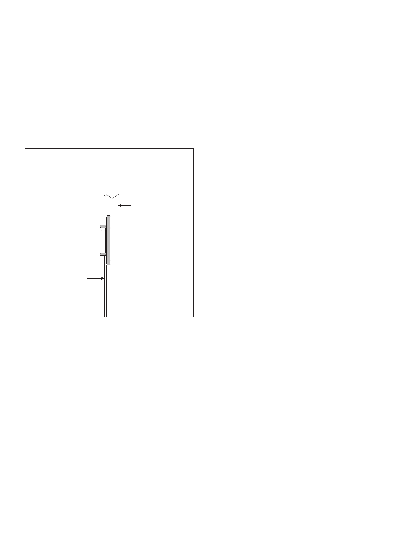
Figure 6.3 Bend Register Cover Tabs
2. Bend over both register cover tabs. See Figure 6.3.
Note: It is permissible to paint the outer wrapping of the
ex vent with black paint, if desired. See Figure 6.4.
Figure 6.4 Paint Outer Wrapping of Flex Vent (Optional)
TABS
LOUVERS FACING THE FRONT OF THE APPLIANCE
(CONTROL SIDE)
Figure 6.5 Correct Register Orientation
WARNING! Risk of Fire! DO NOT block passive heat
registers! Overheating of appliance and combustible
materials will occur.
3. Install register cover with louvers facing the front of the
replace (control side) using provided screws. See
Figure 6.5.
13
Hearth & Home Technologies • PHSI-MCE Instructions • 2560-973 Rev. C • 5/21
Painting
Side Discharge:
If desired nishing includes a painted register cover,
Hearth & Home Technologies recommends using high
temperature paint with a minimum of 300 °F (149 °C) con-
tinuous exposure rating.
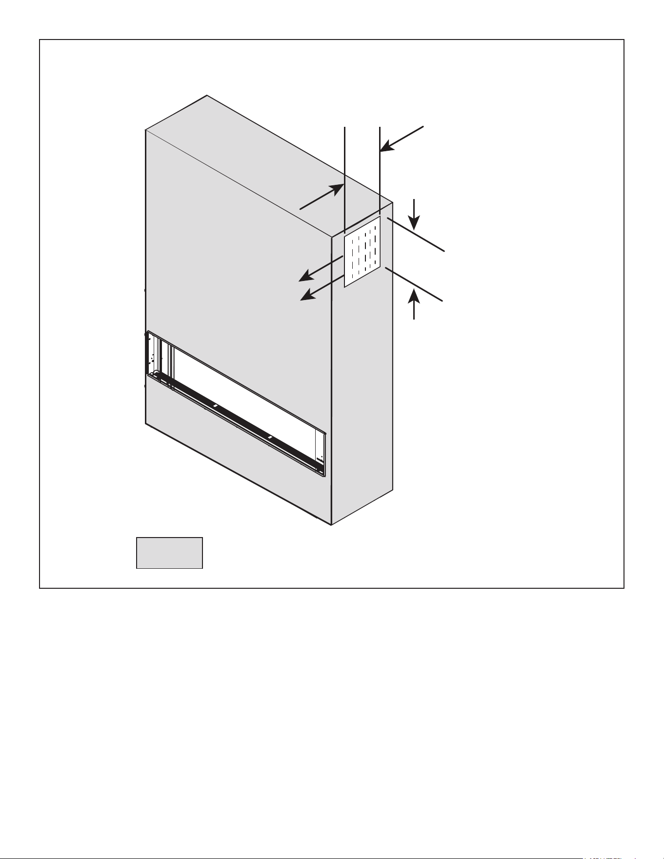
4. Facing Material with Side Discharge Register Cov-
ers
The passive heat kit register covers are designed to
be mounted directly to the drywall surface. Additional
facing materials must not be placed behind the regis-
ter covers. It is acceptable to place Non-Combustible
facing materials up to the edge of the register covers.
See Figure 6.6 and Figure 6.7. Consult the appliance
Installation Manual to determine maximum facing ma-
terial thickness.
5. Install the required register covers as instructed to
complete the installation.
NON-COMBUSTIBLE
FINISHING MATERIAL
1/2 IN. THICK WALL
SHEATHING
NON-COMBUSTIBLE FACING
MATERIAL PLACEMENT
Figure 6.6 Finishing Material Installed
14
Hearth & Home Technologies • PHSI-MCE Instructions • 2560-973 Rev. C • 5/21
Please contact your Hearth & Home Technologies
dealer with any questions or concerns.
For the location of your nearest Hearth & Home Technologies
dealer,
please visit www.hearthnhome.com.
Hearth & Home Technologies
7571 215th Street West, Lakeville, MN 55044
www.hearthnhome.com
CEILING
12-1/4 IN.
(311 mm)
8-3/4 IN.
(222 mm)
SIDE DISCHARGE
(DISCHARGE SLOTS ON BOTH SIDES OF APPLIANCE)
= COMBUSTIBLE MATERIAL ALLOWED
Figure 6.7 Finishing Material Installed