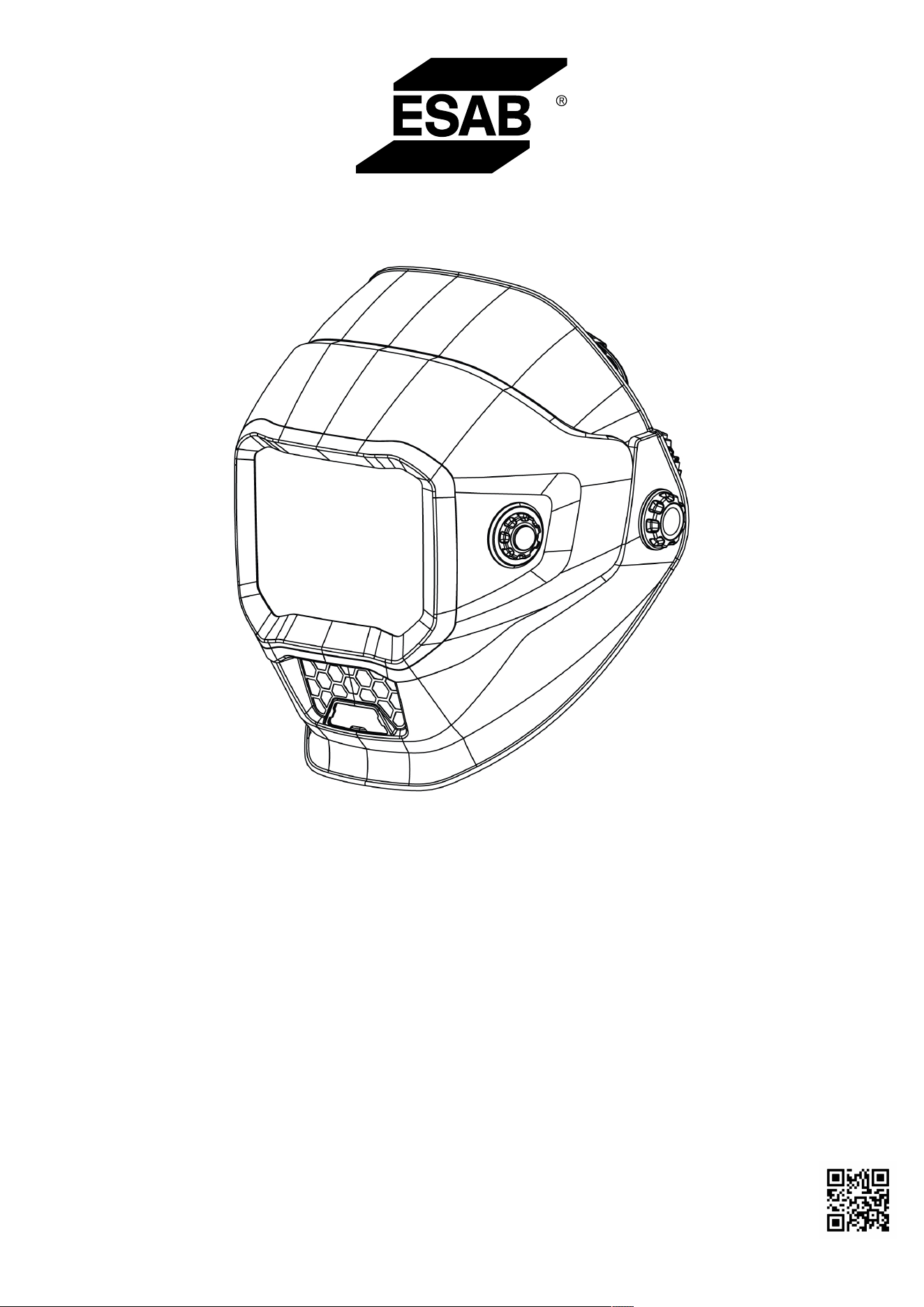
Sentinel A70 PRO
Auto Darkening Welding Helmet
Instruction manual and Spare parts list
PLEASE READ AND UNDERSTAND ALL INSTRUCTION BEFORE USE. RETAIN
THIS MANUAL FOR FUTURE REFERENCE.
Complete User Manual at:
Manual Number: 0448 599 001
Revision Date: 2026-01-16
Revision Number: A
Language: English UK

TABLE OF CONTENTS
0448 599 001
- 3 -
© ESAB AB 2026
1 SAFETY ...................................................................................................................................... 4
1.1 Meaning of symbols .................................................................................................... 4
1.2 Safety instructions for auto-darkening welding helmet and filter .......................... 4
1.3 Safety precautions ...................................................................................................... 5
1.4 California proposition 65 warning ............................................................................. 9
1.5 Regulatory information ............................................................................................... 9
2 INTRODUCTION ......................................................................................................................... 10
2.1 Range of application ................................................................................................... 10
2.2 Shade levels................................................................................................................. 10
2.3 Certification and control labels.................................................................................. 11
2.4 Certification markings explanation ........................................................................... 11
3 TECHNICAL DATA ..................................................................................................................... 12
4 OPERATION ............................................................................................................................... 13
4.1 Battery indicator .......................................................................................................... 13
4.2 Charging the battery ................................................................................................... 13
4.3 Activating the LCD display ......................................................................................... 13
4.4 Locking/unlocking external control function............................................................ 13
4.5 Setting shade number................................................................................................. 14
4.6 Setting sensitivity........................................................................................................ 14
4.7 Setting delay ................................................................................................................ 14
4.8 Cutting mode ............................................................................................................... 15
4.9 Saving parameters to memory settings .................................................................... 15
4.10 Optional settings ......................................................................................................... 15
4.11 Using the work light .................................................................................................... 17
4.12 Removing/installing the ADF flip shell...................................................................... 17
4.13 Adjusting the fit of the helmet.................................................................................... 18
5 MAINTENANCE.......................................................................................................................... 20
5.1 Replacing the grind lens............................................................................................. 20
5.2 Replacing the outer ADF cover lens.......................................................................... 20
5.3 Replacing the inner ADF cover lens.......................................................................... 20
5.4 Replacing the LED work light cover lens .................................................................. 21
5.5 Replacing the auto-darkening filter (ADF) and battery case................................... 21
5.6 Cleaning the equipment.............................................................................................. 22
6 TROUBLESHOOTING ................................................................................................................ 23
SPARE PARTS ...................................................................................................................................... 24
1 SAFETY
0448 599 001
- 4 -
© ESAB AB 2026
1SAFETY
1 SAFETY
1.1 Meaning of symbols
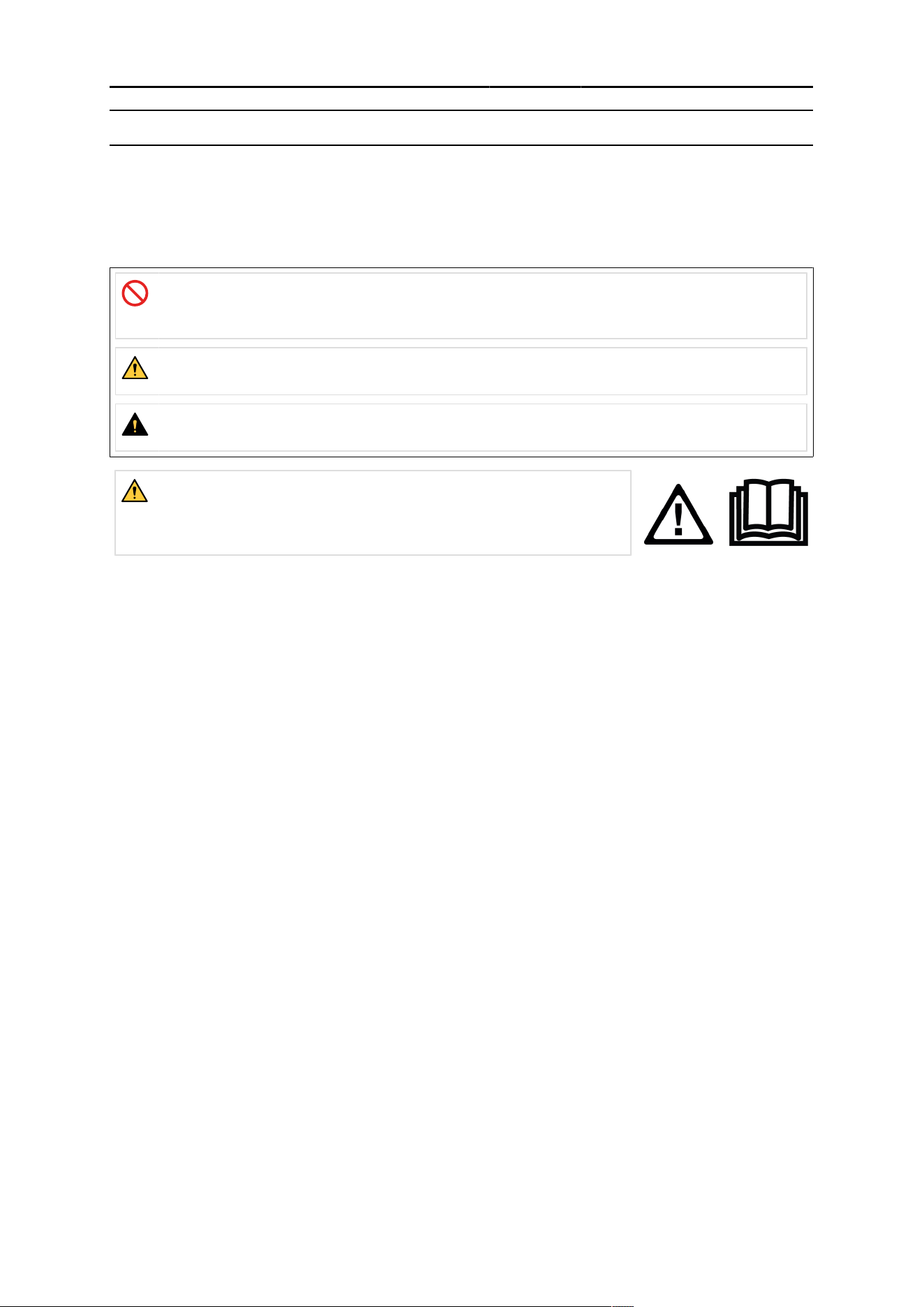
As used throughout this manual: Means Attention! Be Alert!
DANGER!
Means immediate hazards which, if not avoided, will result in immediate, serious
personal injury or loss of life.
WARNING!
Means potential hazards which could result in personal injury or loss of life.
CAUTION!
Means hazards which could result in minor personal injury.
WARNING!
Before use, read and understand the instruction manual and
follow all labels, employer´s safety practices and Safety Data
Sheets (SDSs).
1.2 Safety instructions for auto-darkening welding
helmet and filter
Before use
The auto-darkening welding helmet comes assembled, but before it can be used, perform the
following:
• Adjust the helmet to fit the user properly.
• Check battery surfaces and contacts and clean them if necessary.
• Verify that the battery is in good condition and properly installed.
• Set up for delay time, sensitivity, and shade number for your application.
Usage
• The helmet is not suitable for laser welding.
• Never place the helmet and auto-darkening filter on a hot surface.
• The helmet will not protect against severe impact hazards.
• The helmet will not protect against explosive devices or corrosive liquids.
• Should the helmet not darken upon striking an arc, stop welding immediately and contact ESAB.
• Do not immerse the filter in water.
• The materials which may come into contact with the wearer’s skin can cause allergic reactions in
some circumstances.
• The filter shall only be used in conjunction with the inner cover lens.
Maintenance
• The helmet should be stored in a cool, dry, and dark place. Recharge the battery before long-time
storage.
• Protect filter from contact with liquid and dirt.
○ Clean the filter surface regularly by using clean water and a lint-free or microfiber cloth; do not
use strong cleaning solutions. Always keep the sensors and solar cells clean using a clean
lint-free tissue or microfiber cloth.
○ Regularly replace the cracked/scratched/pitted front cover lens. Avoid setting the helmet down
directly on the cover lens to avoid premature damage to the cover lens.
1 SAFETY
0448 599 001
- 5 -
© ESAB AB 2026
• Never open or tamper with the filter. There are no user-serviceable parts inside.
• Do not make any modifications to either the filter or helmet, unless specified in this manual.
• Only use replacement parts that are specified in this manual.
• Unauthorized modifications and replacement parts will void the warranty and expose the operator to
personal injury.
• Do not use any solvents on the filter screen or helmet components.
1.3 Safety precautions
WARNING!
These Safety Precautions are for your protection. They summarise precautionary information
from the references listed in Additional Safety Information section. Before performing any
installation or operating procedures, be sure to read and follow the safety precautions listed
below as well as all other manuals, material safety data sheets, labels, etc. Failure to observe
Safety Precautions can result in injury or death.
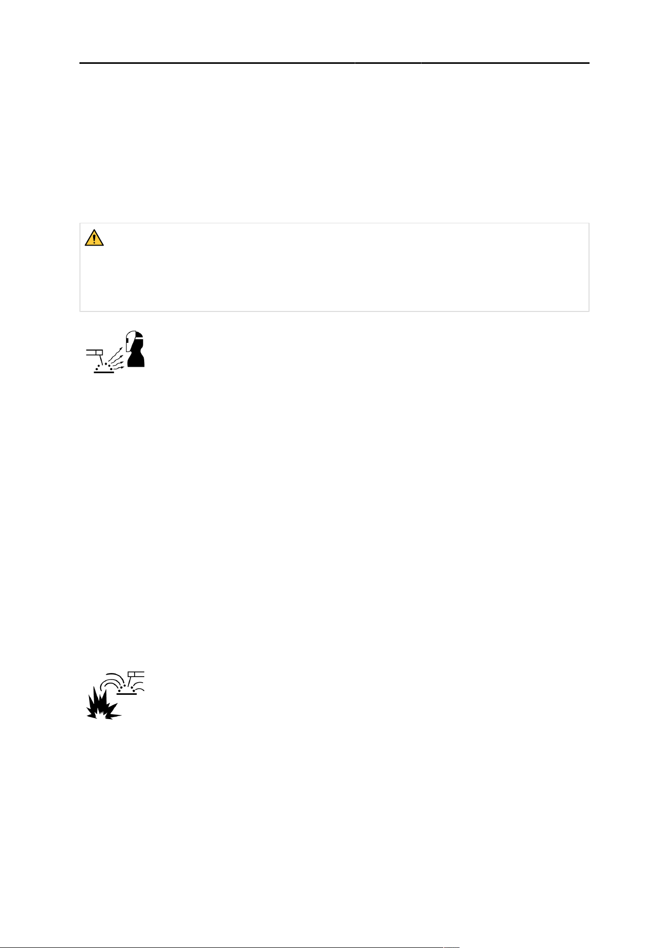
PROTECT YOURSELF AND OTHERS
Some welding, cutting and gouging processes are noisy and require ear
protection. The arc, like the sun, emits ultraviolet (UV) and other radiation
and can injure skin and eyes. Hot metal can cause burns. Training in the
proper use of the processes and equipment is essential to prevent
accidents. Therefore:
1. Wear a welding helmet fitted with a proper shade of filter to protect your face and eyes when
welding or watching.
2. Always wear safety glasses with side shields in any work area, even if welding helmets face shields
and goggles are also required.
3. Use a face shield fitted with the correct filter and cover plates to protect your eyes, face, neck and
ears from sparks and rays of the arc when operating or observing operations. Warn bystanders not
to watch the arc and not to expose themselves to the rays of the electric-arc or hot metal.
4. Wear flameproof gauntlet type gloves, heavy long-sleeve shirt, cuff less trousers, high-topped shoes
and a welding helmet or cap for protection, to protect against arc rays and hot sparks or hot metal.
A flameproof apron may also be desirable as protection against radiated heat and sparks.
5. Hot sparks or metal can lodge in rolled up sleeves, trouser cuffs, or pockets. Sleeves and collars
should be kept buttoned and open pockets eliminated from the front of clothing.
6. Protect other personnel from arc rays and hot sparks with a suitable non-flammable partition or
curtains.
7. Use goggles over safety glasses when chipping slag or grinding. Chipped slag may be hot and can
fly far. Bystanders should also wear goggles over safety glasses.
FIRES AND EXPLOSIONS
Heat from flames and arcs can start fires. Hot slag or sparks can also cause
fires and explosions. Therefore:
1. Protect yourself and others from flying sparks and hot metal.
2. Remove all combustible materials well away from the work area or cover the materials with a
protective non-flammable covering. Combustible materials include wood, cloth, sawdust, liquid and
gas fuels, solvents, paints and coatings paper, etc.
3. Hot sparks or hot metal can fall through cracks or crevices in floors or wall openings and cause a
hidden smoldering fire or fires on the floor below. Make certain that such openings are protected
from hot sparks and metal.
4. Do not weld, cut or perform other hot work until the work piece has been completely cleaned so that
there are no substances on the work piece which might produce flammable or toxic vapors. Do not
do hot work on closed containers, they may explode.
1 SAFETY
0448 599 001
- 6 -
© ESAB AB 2026
5. Have fire extinguishing equipment handy for instant use, such as a garden hose, water pail, sand
bucket, or portable fire extinguisher. Be sure you are trained in its use.
6. Do not use equipment beyond its ratings. For example, an overloaded welding cable can overheat
and create a fire hazard.
7. After completing operations, inspect the work area to make certain there are no hot sparks or hot
metal which could cause a later fire. Use fire watchers when necessary.
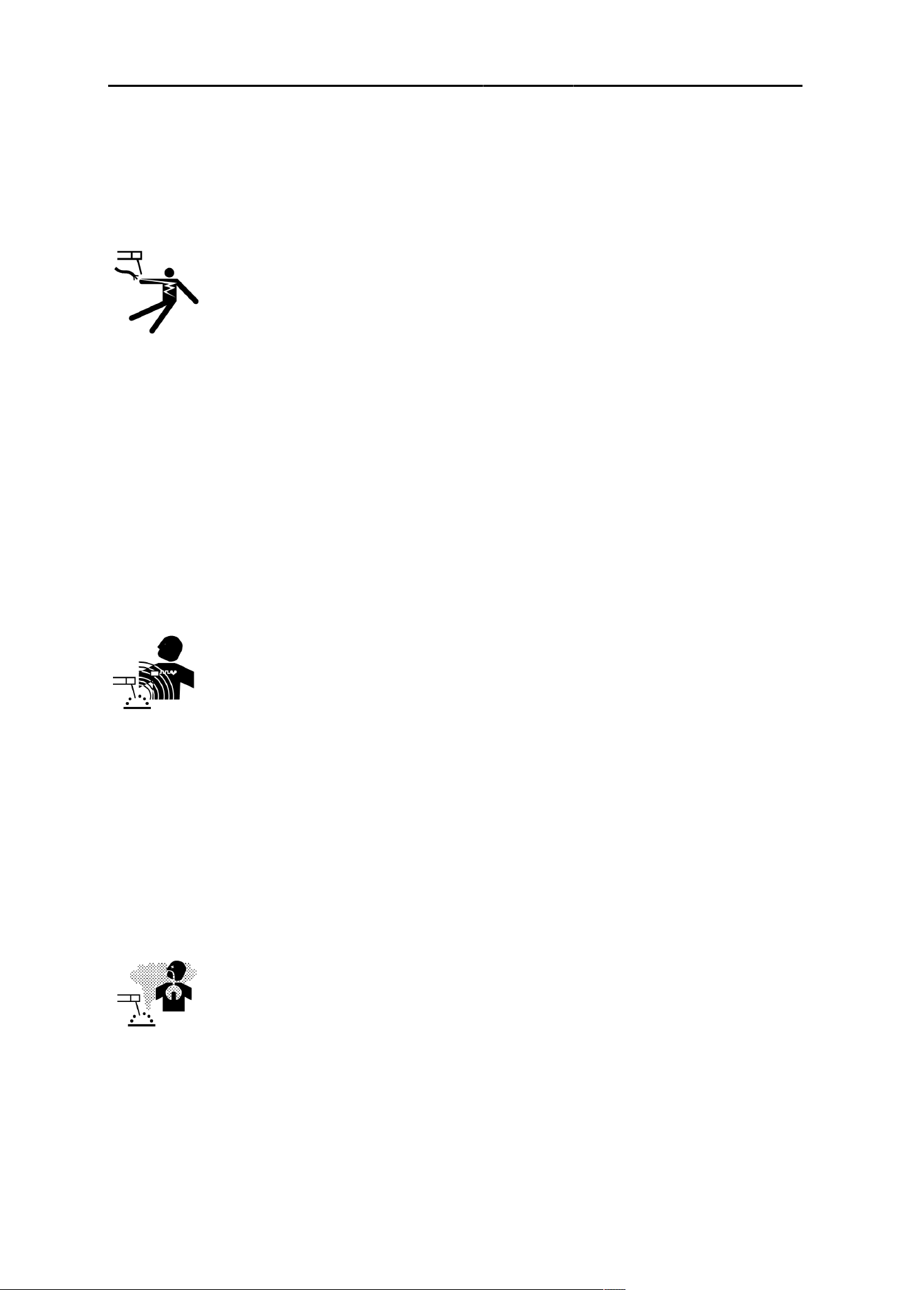
ELECTRICAL SHOCK
Contact with live electrical parts and ground can cause severe injury or
death. DO NOT use AC welding current in damp areas, if movement is
confined, or if there is danger of falling. Therefore:
1. Be sure the power source frame (chassis) is connected to the ground system of the input power.
2. Connect the workpiece to a good electrical ground.
3. Connect the work cable to the workpiece. A poor or missing connection can expose you or others to
a fatal shock.
4. Use well-maintained equipment. Replace worn or damaged cables.
5. Keep everything dry, including clothing, work area, cables, torch/electrode holder and power source.
6. Make sure that all parts of your body are insulated from both the work piece and from the ground.
7. Do not stand directly on metal or the earth while working in tight quarters or a damp area; stand on
dry boards or an insulating platform and wear rubber-soled shoes.
8. Put on dry, hole-free gloves before turning on the power.
9. Turn off the power before removing your gloves.
10.Refer to ANSI/ASC Standard Z49.1 for specific grounding recommendations. Do not mistake the
work lead for a ground cable.
ELECTRIC AND MAGNETIC FIELDS
May be dangerous. Electric current flowing through any conductor causes
localized Electric and Magnetic Fields (EMF). Welding and cutting current
creates EMF around welding cables and welding machines. Therefore:
1. Welders having pacemakers should consult their physician before welding. EMF may interfere with
some pacemakers.
2. Exposure to EMF may have other health effects which are unknown.
3. Welders should use the following procedures to minimise exposure to EMF:
a) Route the electrode and work cables together. Secure them with tape when possible.
b) Never coil the torch or work cable around your body.
c) Do not place your body between the torch and work cables. Route cables on the same side of
your body.
d) Connect the work cable to the workpiece as close as possible to the area being welded.
e) Keep welding power source and cables as far away from your body as possible.
FUMES AND GASES
Fumes and gases, can cause discomfort or harm, particularly in confined
spaces. Shielding gases can cause asphyxiation. Therefore:
1. Keep your head out of the fumes. Do not breathe the fumes and gases.
2. Always provide adequate ventilation in the work area by natural or mechanical means. Do not weld,
cut or gouge on materials such as galvanized steel, stainless steel, copper, zinc, lead beryllium or
cadmium unless positive mechanical ventilation is provided. Do not breathe fumes from these
materials.
3. Do not operate near degreasing and spraying operations. The heat or arc can react with chlorinated
hydrocarbon vapors to form phosgene, a highly toxic gas and other irritant gases.
1 SAFETY
0448 599 001
- 7 -
© ESAB AB 2026
4. If you develop momentary eye, nose or throat irritation while operating, this is an indication that
ventilation is not adequate. Stop work and take necessary steps to improve ventilation in the work
area. Do not continue to operate if physical discomfort persists.
5. Refer to ANSI/ASC Standard Z49.1 for specific ventilation recommendations.
6. WARNING: This product when used for welding or cutting, produces fumes or gases which contain
chemicals known to the State of California to cause birth defects and in some cases cancer
(California Health & Safety Code §25249.5 et seq.)
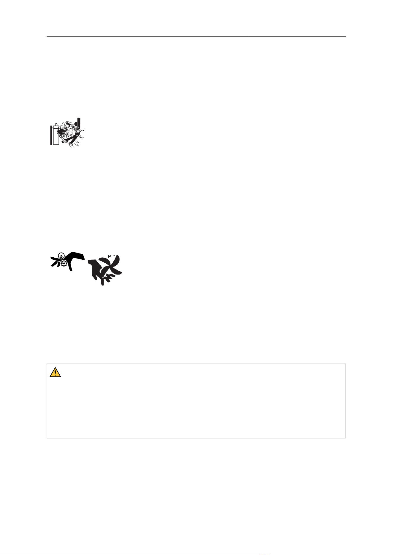
CYLINDER HANDLING
Cylinders, if mishandled, can rupture and violently release gas. A sudden
rupture of cylinder valve or relief device can injure or kill. Therefore:
1. Locate cylinders away from heat, sparks and flames. Never strike an arc on a cylinder.
2. Use the proper gas for the process and use the proper pressure reducing regulator designed to
operate from the compressed gas cylinder. Do not use adaptors. Maintain hoses and fittings in good
condition. Follow manufacturer's operating instructions for mounting regulator to a compressed gas
cylinder.
3. Always secure cylinders in an upright position by chain or strap to suitable hand trucks,
undercarriages, benches, wall, post or racks. Never secure cylinders to work tables or fixtures
where they may become part of an electrical circuit.
4. When not in use, keep cylinder valves closed. Have valve protection cap in place if regulator is not
connected. Secure and move cylinders by using suitable hand trucks.
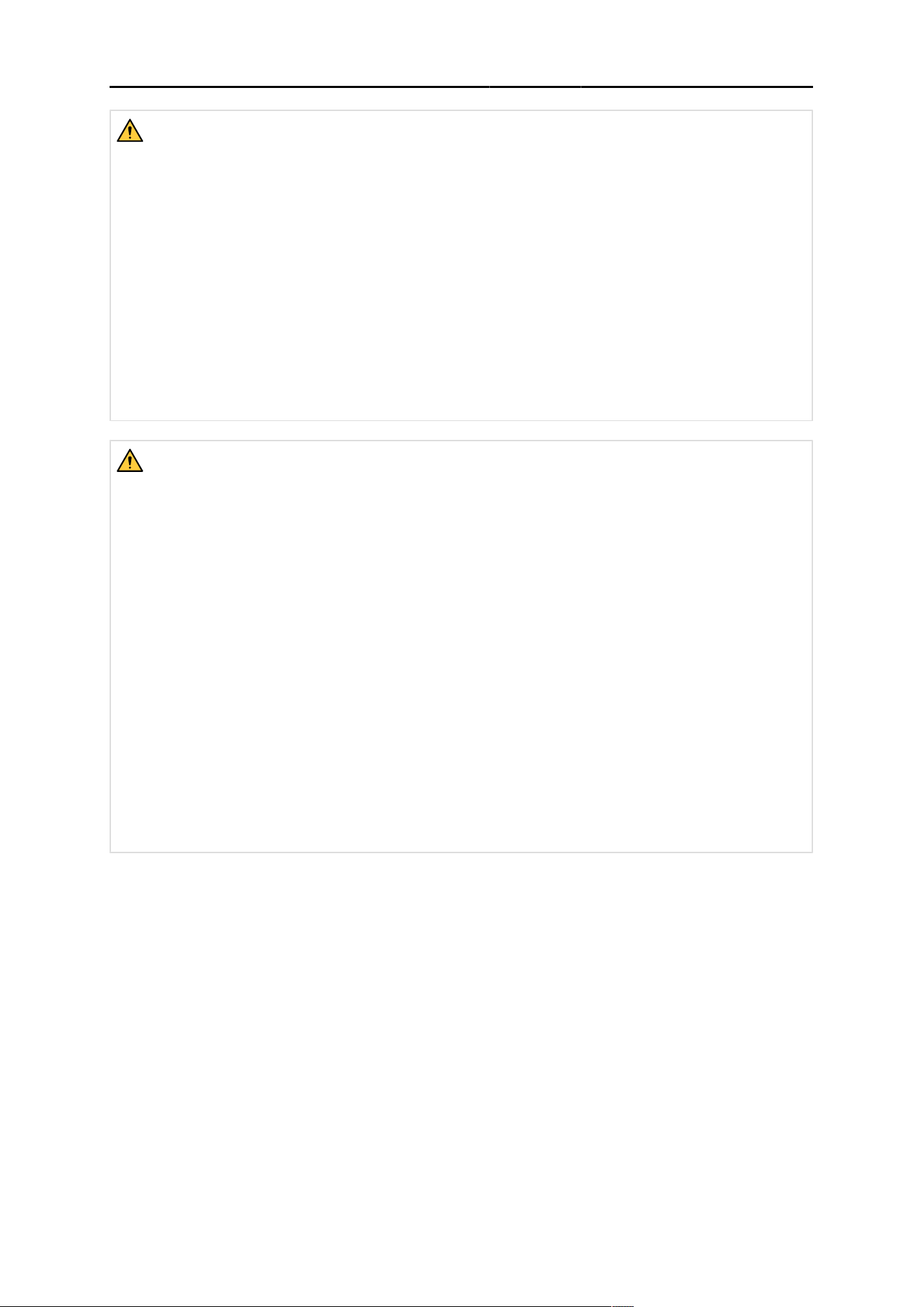
MOVING PARTS
Moving parts, such as fans, rotors and belts can cause injury.
Therefore:
1. Keep all doors, panels, guards and covers closed and securely in place.
2. Stop engine or drive systems before installing or connecting unit.
3. Have only qualified people remove covers for maintenance and troubleshooting as necessary.
4. To prevent accidental starting of equipment during service, disconnect negative (-) battery cable
from battery.
5. Keep hands, hair, loose clothing and tools away from moving parts.
6. Reinstall panels or covers and close doors when service is finished and before starting engine.
WARNING!
FALLING EQUIPMENT CAN INJURE
• Only use lifting eye to lift unit. Do NOT use running gear, gas cylinders or any other
accessories.
• Use equipment of adequate capacity to lift and support unit.
• If using lift forks to move unit, be sure forks are long enough to extend beyond opposite side
of unit.
• Keep cables and cords away from moving vehicles when working from an aerial location.
1 SAFETY
0448 599 001
- 8 -
© ESAB AB 2026
WARNING!
EQUIPMENT MAINTENANCE
Faulty or improperly maintained equipment can cause injury or death. Therefore:
1. Always have qualified personnel perform the installation, troubleshooting and maintenance
work. Do not perform any electrical work unless you are qualified to perform such work.
2. Before performing any maintenance work inside a power source, disconnect the power
source from the incoming electrical power.
3. Maintain cables, earthing wire, connections, power cord and power supply in safe working
order. Do not operate any equipment in faulty condition.
4. Do not abuse any equipment or accessories. Keep equipment away from heat sources such
as furnaces, wet conditions such as water puddles, oil or grease, corrosive atmospheres
and inclement weather.
5. Keep all safety devices and cabinet covers in position and in good repair.
6. Use equipment only for its intended purpose. Do not modify it in any manner.
WARNING!
WELDING HELMET CRITERIA
1. The protection according to Z87.1 is only given if it is ensured that the product is assembled
according to the manufacturer's instructions.
2. The eye-protectors against high-speed particles worn over standard ophthalmic spectacles
may transmit impacts, thus creating a hazard to the wearer.
3. If the impact letter followed by letter "T", you can use it for protection against high-speed
particles at extremes of temperature. If the impact letter does not follow by letter "T", you
should only use the eye protector for protection against high-speed particles at room
temperature.
4. A visual inspection of the complete protector is necessary before each use.
5. This protector is appropriate for the headform 1-M.
6. Protector can affect the recognition of colours and/or signal light detection.
7. Protectors that have been subject to impact shall not be used and shall be discarded and
replaced.
8. If the impact level symbols are not equal on both the lens/filter and the frame, then it is the
lower level that shall be assigned to the complete protector.
9. The protections corresponding to the code numbers/letter 7, 9, CH are provided by the
complete protector only if the respective symbols are equal on both the lens and the frame.
10.Not suitable for driving and road use.
1 SAFETY
0448 599 001
- 9 -
© ESAB AB 2026
CAUTION!
ADDITIONAL SAFETY INFORMATION
For more information on safe practices for electric arc welding and cutting equipment,
ask your supplier for a copy of “Precautions and Safe Practices for Arc Welding,
Cutting and Gouging”, Form 52-529.
The following publications are recommended:
• ANSI/ASC Z49.1 - “Safety in Welding and Cutting”
• AWS C5.5 - “Recommended Practices for Gas Tungsten Arc Welding”
• AWS C5.6 - “Recommended Practices for Gas Metal Arc welding”
• AWS SP - “Safe practices” - Reprint, Welding Handbook
• ANSI/AWS F4.1 - “Recommended Safe Practices for Welding and Cutting of Containers
That Have Held Hazardous Substances”
• OSHA 29 CFR 1910 - "Safety and health standards"
• CSA W117.2 - "Code for safety in welding and cutting"
• NFPA Standard 51B, “Fire Prevention During Welding, Cutting, and Other Hot Work"
• CGA Standard P-1, “Precautions for Safe Handling of Compressed Gases in Cylinders”
• ANSI Z87.1, "Occupational and Educational Personal Eye and Face Protection Devices"
1.4 California proposition 65 warning
WARNING!
Welding or cutting equipment produces fumes or gases which contain chemicals known in the
State of California to cause birth defects and, in some cases, cancer. (California Health &
Safety Code Section 25249.5 et seq.)
WARNING!
This product can expose you to chemicals including lead, which are known to the state of
California to cause cancer and birth defects or other reproductive harm. Wash hands after use.
For more information, go to www.P65Warnings.ca.gov.
1.5 Regulatory information
Please take attention that changes or modification not expressly approved by the party responsible for
compliance could void the user’s authority to operate the equipment.
This device complies with Part 15 of the FCC Rules. Operation is subject to the following two
conditions:
(1) This device may not cause harmful interference, and
(2) This device must accept any interference received, including interference that may cause
undesired operation.
2 INTRODUCTION
0448 599 001
- 10 -
© ESAB AB 2026
2INTRODUCTION
2 INTRODUCTION
The Sentinel A70 PRO is a light weight welding helmet intended for use in electric arc welding to
protect against UV/IR rays, heat and sparks in any state from clear to dark. The protection shades of
the welding helmets have been chosen to avoid eye damage caused by the welding arc. The helmet
does not have to be flipped up and down during welding so both hands are kept free.
ESAB has an assortment of welding accessories and personal protection equipment for
purchase. For ordering information contact your local ESAB dealer or visit us on our website.
2.1 Range of application
The Sentinel A70 PRO welding helmet can be used for the following applications:
• Electrode
• MIG
• Mag
• TIG (>=3A)
The Sentinel A70 PRO welding helmets are not suitable for use with laser systems and oxyacetylene
(gas welding) applications. The welding filter must not be used for any other purpose other than arc
welding. The helmet should never be used as sunglasses when driving as this could lead to incorrect
identification of the color of traffic light.
The automatic welding filter will operate well under extreme low light conditions and very strong
sunlight.
2.2 Shade levels
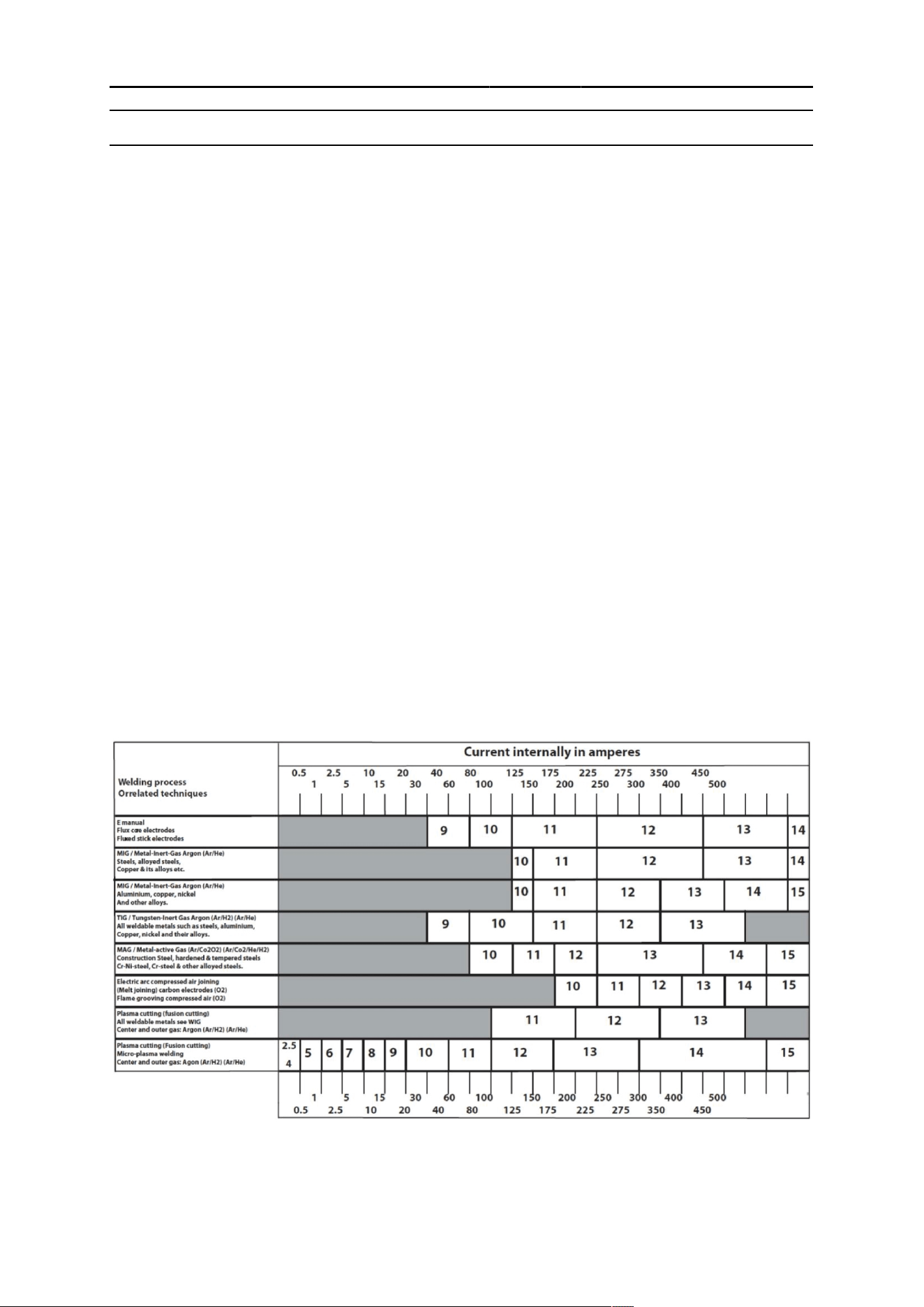
Sentinel A70 PRO welding helmets may be used only in connection with arc welding. The following
table shows how to choose the most suitable shade level:
(1)
As a rule of thumb, start with a shade that is too dark, then go to a lighter shade which gives a
sufficient view of the weld zone without going below the minimum. In oxyfuel gas welding or cutting
where the torch produces a high yellow light, it is desirable to use a filter lens that absorbs the yellow
or sodium line the visible light of the (spectrum) operation.
2 INTRODUCTION
0448 599 001
- 11 -
© ESAB AB 2026
(2)
These values apply where the actual arc is seen. Experience has shown that lighter filters may be
used when the arc is hidden by the workpiece. Data from ANSI Z49.1-2005.
2.3 Certification and control labels
European conformity mark.
This confirms that the product fulfils the requirements of the PPE Regulation 2016/425.
2.4 Certification markings explanation
Welding helmet
EN ISO 16321: 16321 ESAB W15 E 1-M CE
16321 = Number of the standard
ESAB = Manufacturer code
W15 = PROimum shade number of welding filter
E = Impact level (120 m/s)
1-M = Head-form size
CE = European Conformity
Front/inside cover lens
EN ISO 16321: ESAB 1 E CE
ESAB = Manufacturer code
1 = Enhanced optical performance
E = Impact level (120 m/s)
CE = European Conformity
Auto-darkening filter
EN ISO 16321: 16321 ESAB W3/5-13 V1 CE
16321 = Number of the standard
ESAB = Manufacturer code
W = Welding filter
3 = Light state scale number
This helmet was tested and certified by:
ECS GmbH
Huettfeldstrasse 50, Obere Bahnstrasse 74
73430 AALEN, GERMANY
Notified body number 1883
3 TECHNICAL DATA
0448 599 001
- 12 -
© ESAB AB 2026
3TECHNICALDATA
3 TECHNICAL DATA
Dimensions l×w×h 280 × 286 × 332 mm
Weight 900 g
Optical class ISO V1
Viewing area 123 × 76 mm (4.65'' × 2.8'')
Arc sensors 4
Light state DIN 3
Grind state DIN 3
Welding mode Shade No. from 5-9/9-13
Shade control Internal and external digital control
Power On/Off Automatic On/Off
Sensitivity control 10-step, digital control (internal and external)
UV/IR protection Up to shade DIN 16 at all times
Power supply Solar cell. Rechargable Li-Ion battery
Switching time 1/25,000 s. from light to dark
Grinding Yes – through flip-up ADF design
Cutting Selectable from shade 5-13
Delay (dark to light) 10-step, digital control (internal and external)
from 0.1 ~ 0.9 s
Low amperage TIG rated ≥ 3 amps
Operating temperature -10℃ to 65℃ (14℉ to 149℉)
Storing temperature -20℃ to 85℃ (-4℉ to 185℉)
Approved certifications CE, ANSI Z87.1, CSA Z94.3, AS/NZS 1338.1
4 OPERATION
0448 599 001
- 13 -
© ESAB AB 2026
4OPERATION
4 OPERATION
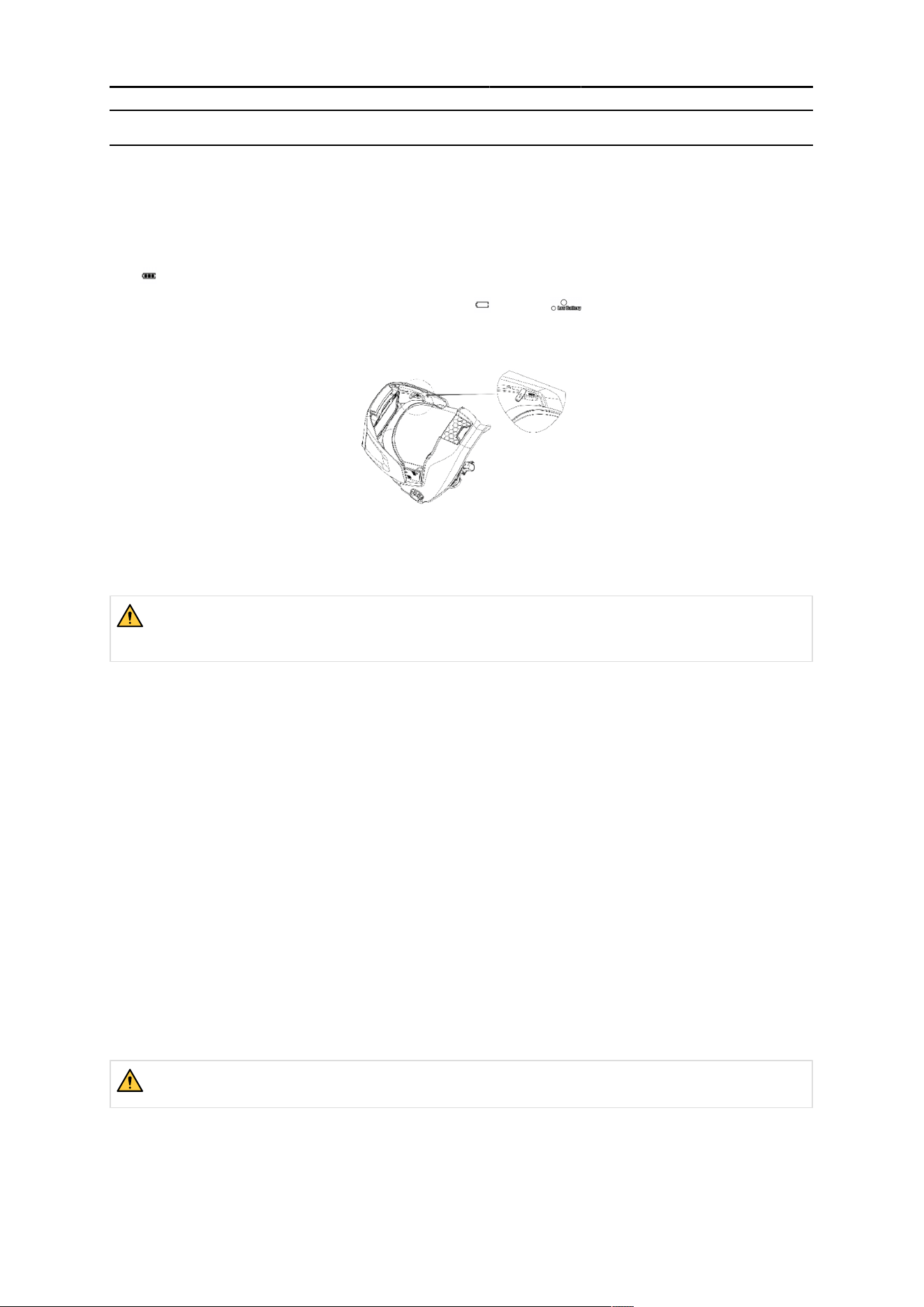
4.1 Battery indicator
This Auto-Darkening Filter (ADF) is powered by a rechargeable battery.
The symbol shows the current state of the battery.
Charge the battery when the indicator symbol shows and the red LED is continuously
illuminated.
4.2 Charging the battery
WARNING!
Fully charge the battery before initial use! Charge the battery when “Low battery” LED is
illuminated.
1) Locate the USB-C charge port.
2) Open the protective cover on charge port.
3) Charge by using the included USB-C type cable connected to a power source of 5V/2A.
The ADF screen shows the charge status.
4.3 Activating the LCD display
1) Press any button on the ADF’s control panel or press the external button to activate the
LCD display.
The LCD display automatically turns off after 3 seconds if there is no operation. Symbols on the LCD
display are illuminated with a yellow block during adjustment.
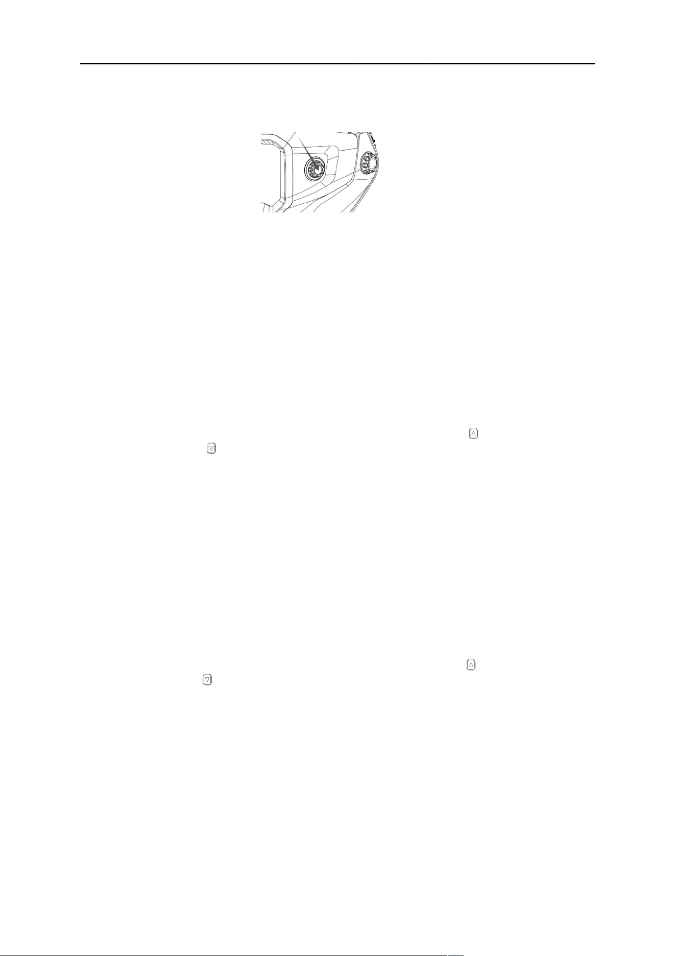
4.4 Locking/unlocking external control function
WARNING!
Unlock the external control function when using the external control!
4 OPERATION
0448 599 001
- 14 -
© ESAB AB 2026
1) Press the external button, as shown in the following illustration, to unlock the external
control function.
The external control function locks when the LCD display is blank or inactive.
4.5 Setting shade number
Shade selection can only be adjusted while using the welding mode.
1) Select “Welding mode” by pressing the external button for more than 2 seconds, or press
the “Mode” button on the internal ADF control panel.
2) Select the shade number by pressing the external button on shell, or press the “Set” button
on the internal ADF control panel. The shade number is illuminated by a yellow block when
the setting is ready for adjustment.
3)
Rotate the external control dial to adjust shade from shade 5-13; or press to increase
the shade number or to reduce the shade setting on the internal ADF control panel.
4) Select the proper shade number for your welding or cutting process according to the shade
level table in this manual.
4.6 Setting sensitivity
Sensitivity can be adjusted only while using the welding mode.
1) Select “Welding mode” by pressing the external button for more than 2 seconds, or press
the “Mode” button on the internal ADF control panel.
2) Select the sensitivity setting by pressing the external button until the “Sens” setting is
illuminated by a yellow box, or press the “Set” button on the internal ADF control panel.
3)
Rotate external control to adjust sensitivity level from level 1-10, or press to increase the
sensitivity level, and to reduce the sentivity level on internal ADF control panel.
The sensitivity setting allows the ADF to become more or less sensitive to arc light, for different
welding processes.
• Low sensitivity is suitable for outdoor use where excessive ambient/environmental light conditions
exist, and/or with higher amperage SMAW and FCAW operations.
• High sensitivity is suitable for low amperage welding typically used with GTAW or GMAW
operations.
• Under normal welding conditions, a higher sensitivity setting is recommended.
4.7 Setting delay
Delay can be adjusted only while using the welding mode.

4 OPERATION
0448 599 001
- 15 -
© ESAB AB 2026
1) Select “Welding mode” by pressing the external button for more than 2 seconds, or press
the “Mode” button on the internal ADF control panel.
2) Select the sensitivity setting by pressing the external button until the “Delay” setting is
illuminated by a yellow box, or press the “Set” button on the internal ADF control panel.
3)
Rotate external control to adjust delay level from level 1-10, or press to increase the
Delay level, and to reduce the sentivity level on internal ADF control panel .
The delay setting adjusts the amount of time the ADF takes to lighten back to shade 3 after welding.
• The longest time is about 0.9 seconds depending upon welding point temperature and the shade
setting. This setting is ideal for welding at high amperage where there is an afterglow from the
welding operation.
• The shortest time is about 0.1 second depending upon welding point temperature and shade
setting. This setting is ideal for tack welding or production welding with short weld durations.
4.8 Cutting mode
1) Select “Cutting mode” by pressing the external button for more than 2 seconds, or press
the “Mode” button on the internal ADF control panel.
“Cutting” shows in the internal display to indicate the selected mode, and a green LED light
flashes continuously.
2) Rotate external control to adjust shade number from 5-13, or select the shade number from
5-13 by pressing and on the ADF’s internal control panel.
3) Press the external button for more than 2 seconds on shell, or press the “Mode” button on
the internal ADF control panel to revert the ADF back to “welding mode".
4.9 Saving parameters to memory settings
It's possible to save the setting parameters into a memory setting. Users can recall a memory at any
time they need. The system can save up to 20 sets of parameters. Take memory setting 1 as an
example:
1) Set shade, sensitivity, and delay according to previously steps.
2)
Press the button on the ADF control panel for more than 2 seconds, and select memory
set to position “1” by pressing or .
3) Press the “set” button or press the external button.
The memory position will be position “1”.
4) MEMORY 2 to MEMORY 20 can be set the same way.
Users can call out the MEMORY setting by selecting the memory position via short press
“MEMORY” first and then choosing the desired memory number via and . The ADF
will change to the selected setting from memory automatically after 10 seconds.
4.10 Optional settings
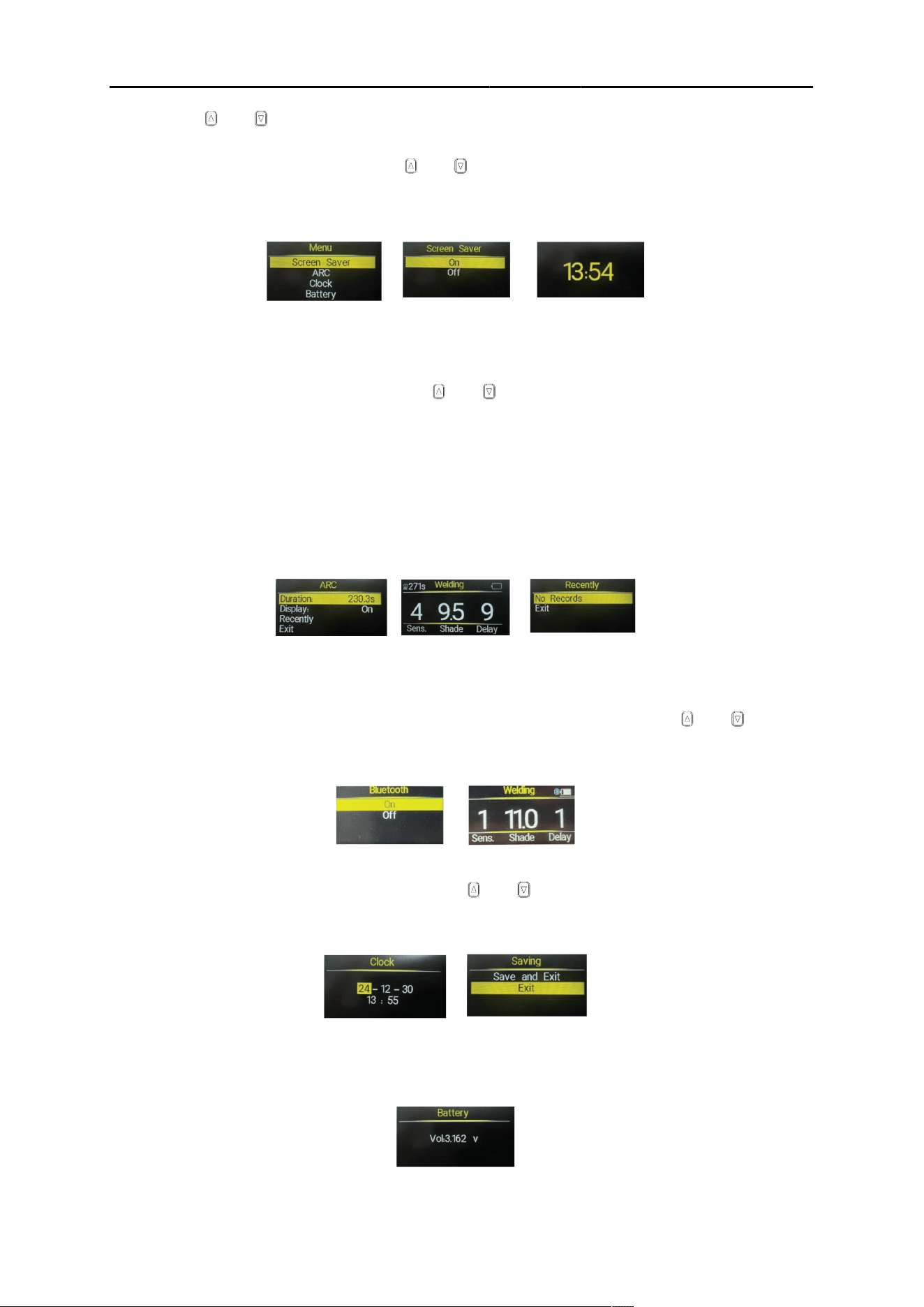
1) Press the “set” button on ADF’s internal control panel for more than 2 seconds to open the
optional settings menu.
4 OPERATION
0448 599 001
- 16 -
© ESAB AB 2026
2)
Press the and buttons to select various parameter settings.
a) Screen saver
Choose ON/OFF by by pressing the and buttons and then press “set” confirm and
exit.
When “ON” is chosen, the LCD display will show a 24-hour clock clock .
b) ARC –welding acr recording
ARC is used to record the amount of time the ADF has spent in any darkened or active
state.
To choose a different function, press the and buttons, and exit by pressing the
“set” button after choosing the “Exit” icon
Duration = Total ADF activation time during one day . This setting will clear and revert to
“0” when the clock reaches “0:00”. Press “set” will clear all of the data.
Display = Total welding time record. This will show at the left corner of LCD display
when “ON” is selected.
Recent = Total ARC activation time over the course of 7 days. Press “Set” to review the
data .
c) Bluetooth
Bluetooth is available to connect the helmet operations to a mobile device. The helmet
may be used with the ESAB mobile app to to change settings on the helmet, view data
and find helpful online tools. Toggle the BT function ON/OFF by pressing the and
buttons to select and then press “set” confirm and exit. The LCD display will include a
Bluetooth icon when the function is set to “on”.
d) Clock
Set the current date and time by pressing the and buttons to to increase and
reduce the selected value. Setting values follow Year -> Month -> Day -> Hour ->
Minutes-> Save and Exit/ Exit in sequence by pressing the “set” button.
e) Battery
The battery function will show the actual real time battery voltage. Exit by pressing the
“set” button.
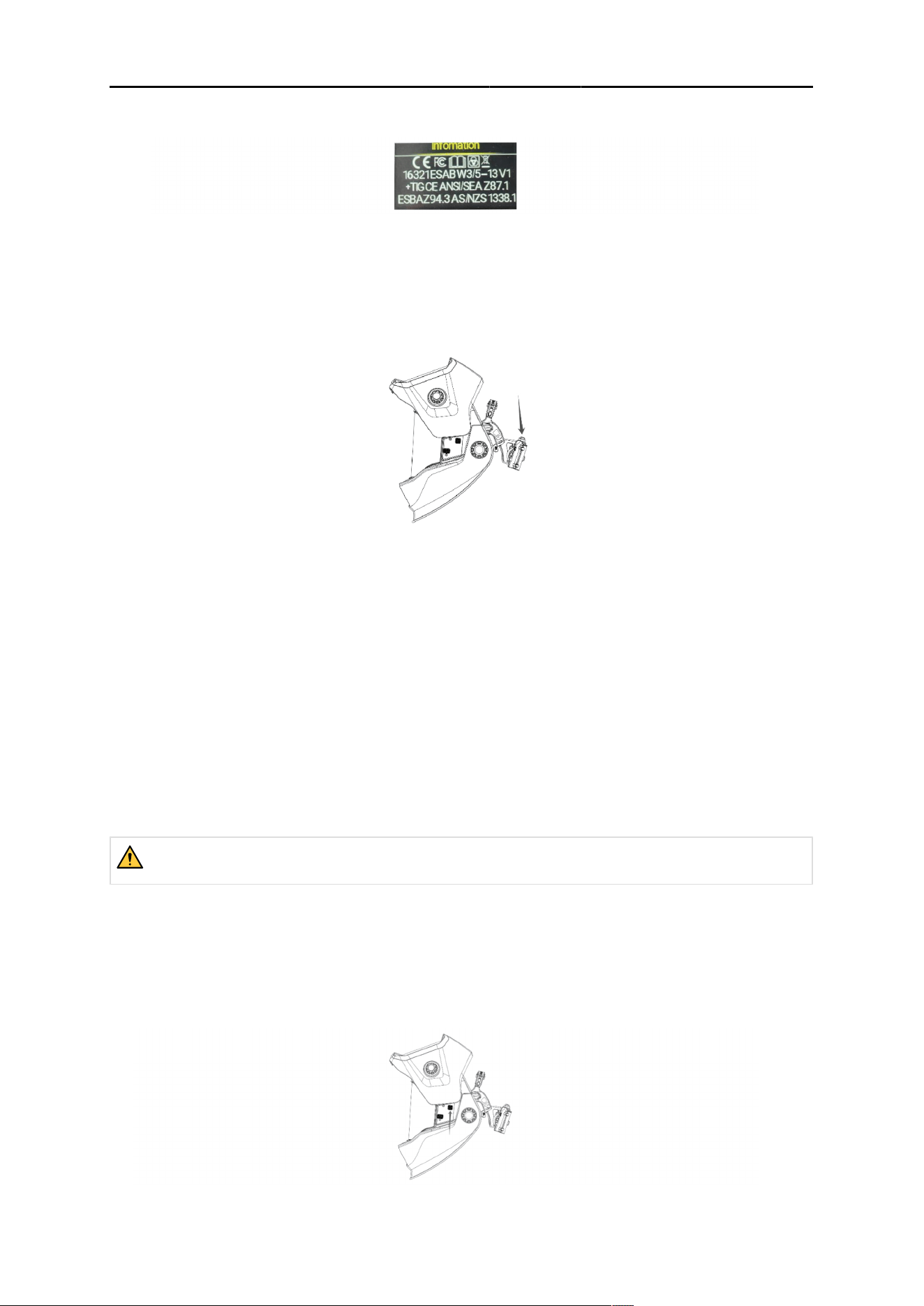
f) Infomation
The information function will display the associated certificates to which the helmet is
tested.
4 OPERATION
0448 599 001
- 17 -
© ESAB AB 2026
Exit by pressing the “set” button.
4.11 Using the work light
The LED work light, located at the bottom of the main helmet shell, is powered by its own “AA” battery,
which is located on the back of the headgear.
1) Press the button located on top of the battery case to turn the work light on or off.
When an arc or strong ambient light is detected, the work light will automatically turn off,
and turn on again when the arc is complete or the ambient conditions darken. This allows
premium battery life.
2) To install and replace the “AA” battery, lift the cover of the battery compartment to access
the battery.
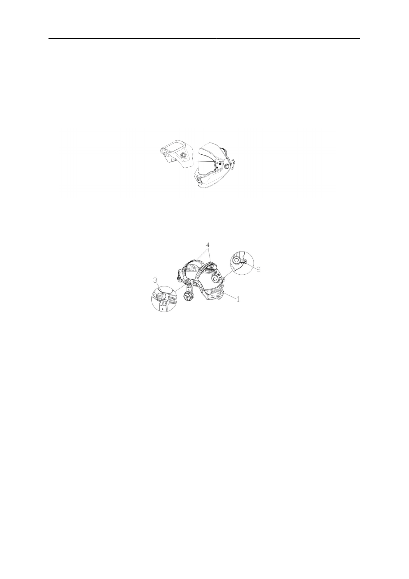
4.12 Removing/installing the ADF flip shell
The Sentinel A70 PRO helmet can be used as a grinding helmet by flipping up the outer ADF shell or
by removing the outer ADF shell completely. Removing the shell allows for a better configuration
during longer grinding or other finishing operations.
WARNING!
Only weld when the ADF shell is attached and in the lowered position!
Removing the outer ADF shell
1) Raise the outer ADF shell.
2) Press both of the upper buttons buttons found on the outer sides of the main shell.
3) While pressing both buttons, slide the outer ADF shell forward to remove.
4 OPERATION
0448 599 001
- 18 -
© ESAB AB 2026
Installing the outer ADF shell
1) Reverse the removal process by sliding the ADF shell into the guide slots. The outer ADF
shell must be in the “raised” position.
2) The outer ADF shell will click into place on both sides of the main shell when it is seated
correctly.
3) Ensure that the outer ADF shell is correctly and firmly attached prior to any welding
or cutting operation.
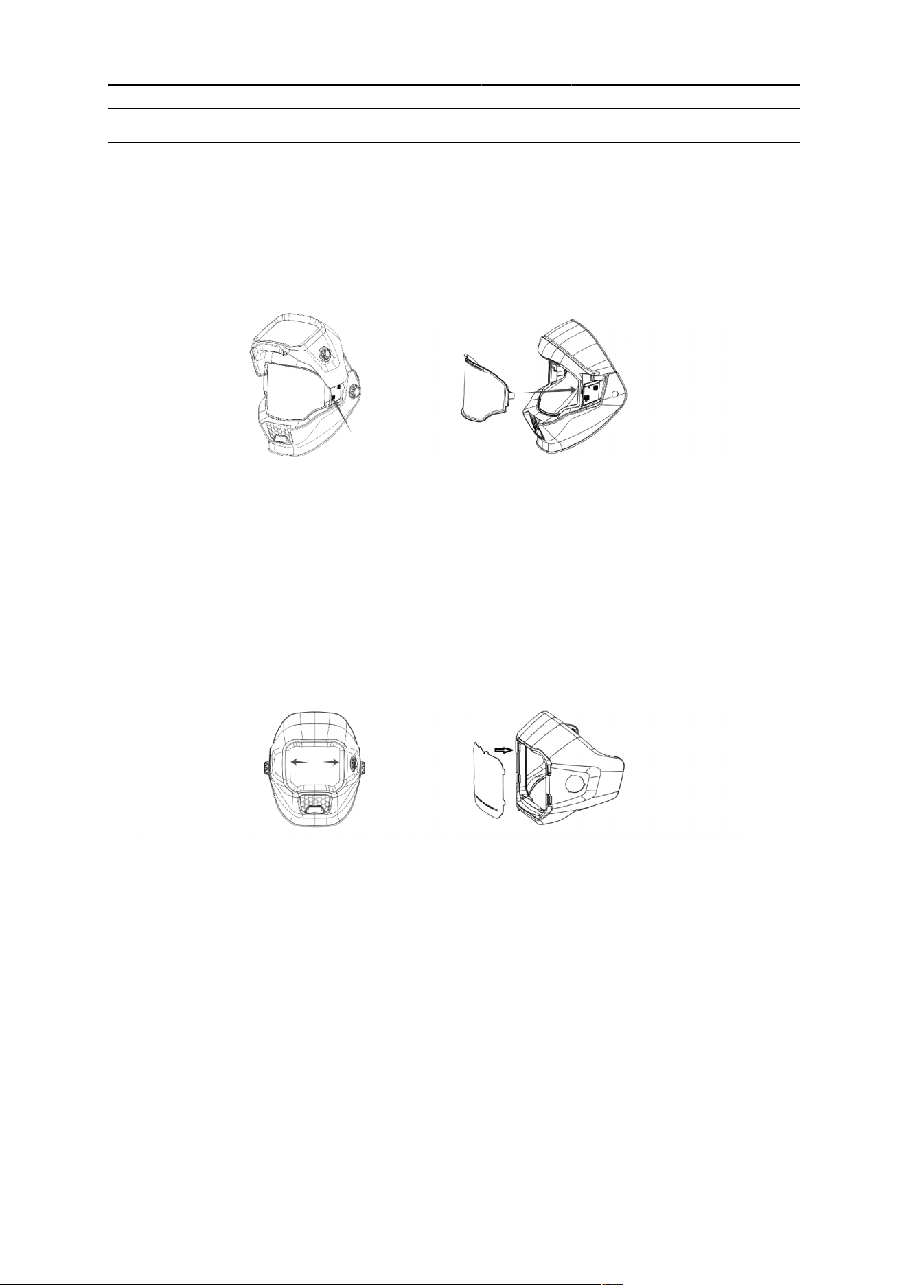
4.13 Adjusting the fit of the helmet
Adjusting the circumference of the headband
1) Rotate the knob (1) on the back of the headband to make the overall circumference of the
headband larger or smaller.
This can be done while wearing the helmet and allows easy micro-level tension adjustment
to keep the helmet firmly on the head without it being too tight.
2) If the headband is riding too high or too low on your head, adjust the straps (4) which
passes over the top of your head.
a) Release the end of the band by pushing the locking pin out of the band’s hole.
b) Slide the two portions of the band to a greater or lesser width as required.
c) Push the locking pin through the nearest hole.
Adjusting the distance between the helmet and face
1) Press and hold the slider locking mecahnism (3) on both sides, and slide the headgear
back and forth within the helmet.
2) Ensure the slider is locked back into position and make certain the distance between the
lens to both eyes is equal. This avoids issues with uneven ADF darkness.
Adjusting view angle position
1) The tilt adjustment is located on the right side of the helmet.
2) Loosen the right headgear tension knob (2) and adjust the lever forward or back to the
desired position.

4 OPERATION
0448 599 001
- 19 -
© ESAB AB 2026
3) Retighten the right headgear tension knob.
5 MAINTENANCE
0448 599 001
- 20 -
© ESAB AB 2026
5MAINTENANCE
5 MAINTENANCE
5.1 Replacing the grind lens
Replace the grind lens if it becomes scratched or damaged.
1) Press the lower-positioned buttons on both side of shell and remove the grind lens by
pulling forward.
2) To install the grind lens, simple insert both sides into the slots. The grind lens locks
automaticly when installed properly and sounds a click.
5.2 Replacing the outer ADF cover lens
Replace the outer ADF cover lens if it becomes scratched or damaged.
1) Pull the front cover retainer bracket from both sides to remove the retainer.
2) Remove the cover lens by grasping the lens from the top and pulling forward.
3) Place a new lens in the shell by gently bending the lens and setting the left and right edges
into the slots located on the ADF shell.
4) Reinstall the front cover retainer bracket.
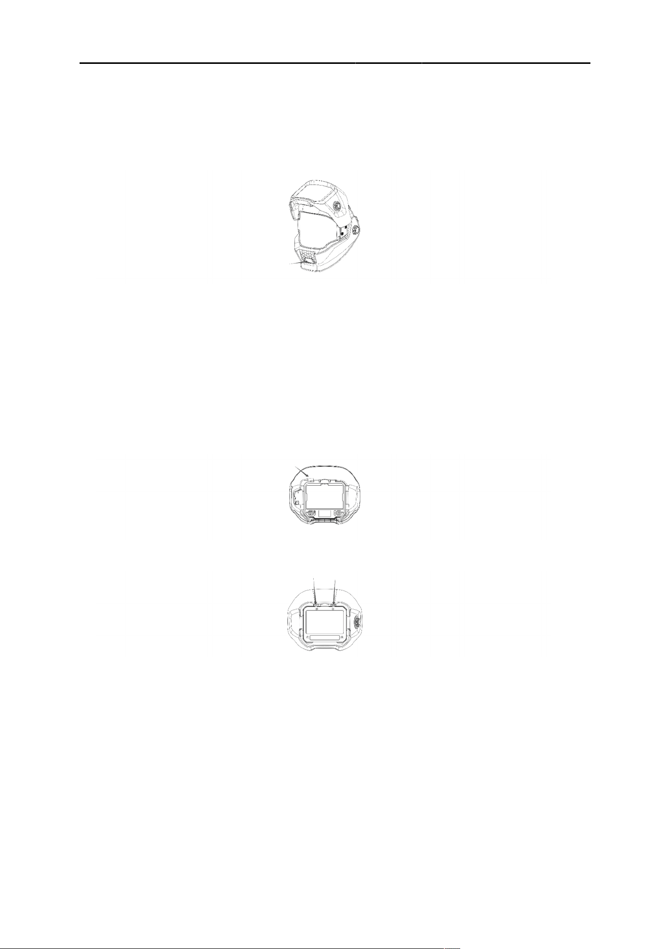
5.3 Replacing the inner ADF cover lens
Replace the inner ADF cover lens if it becomes scratched or damaged.
1) Remove the outer ADF shell as noted in the instruction “Removing and installing the ADF
flip shell” .
2) Lift the inner ADF cover lens at the recess found at the top of the ADF. The inside cover
lens will flex upward and release from the cartridge.
3) To install a new inner cover lens, gently bend the lens and place the left and right edges
into the retaining bracket.
5 MAINTENANCE
0448 599 001
- 21 -
© ESAB AB 2026
5.4 Replacing the LED work light cover lens
Replace the LED light cover lens if it is damaged.
1) Remove the cover lens by pulling the lens out by using the cutout on the lens found at the
bottom center.
2) Reinstall a new cover lens by inserting both edges into the bracket.
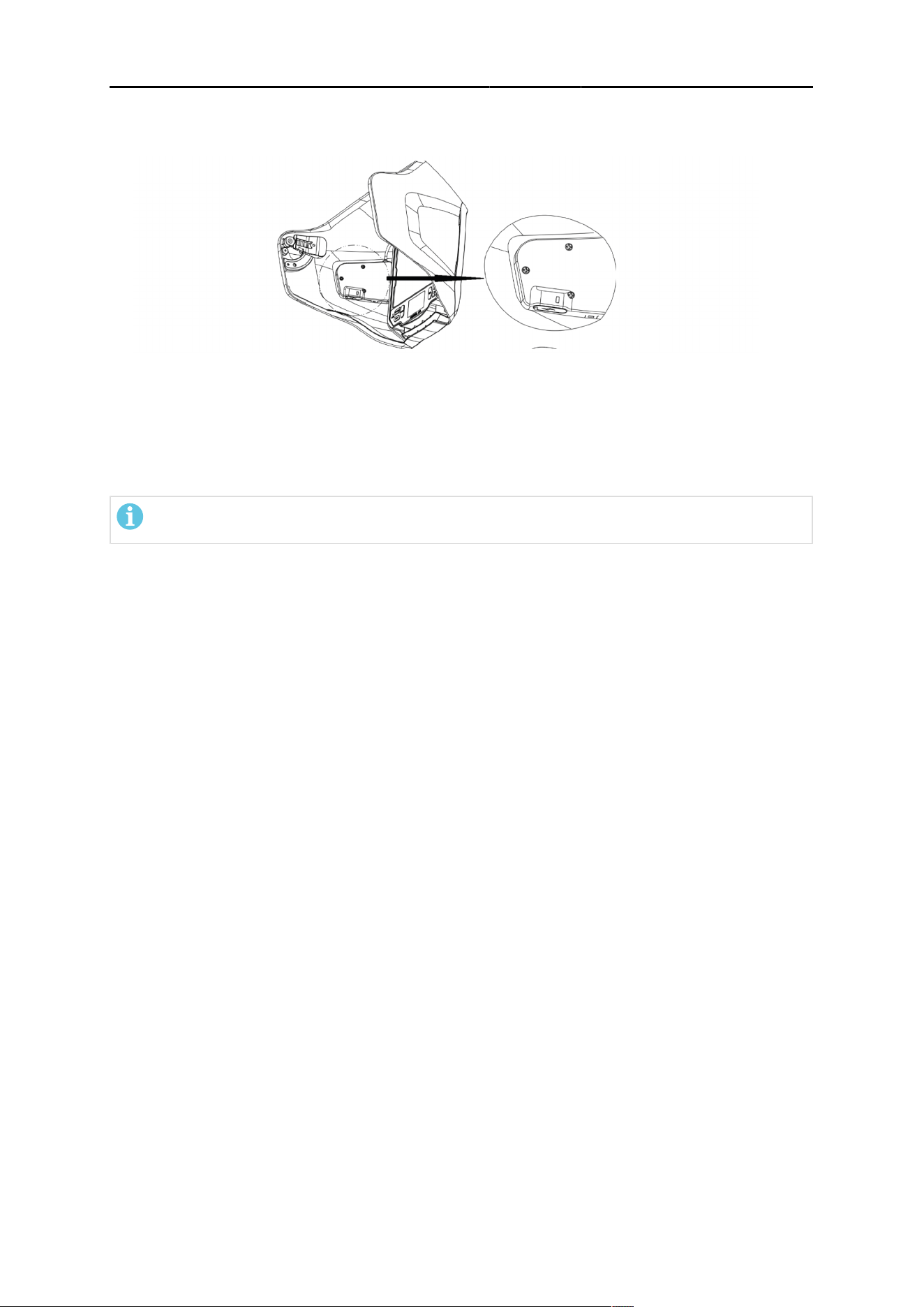
5.5 Replacing the auto-darkening filter (ADF) and
battery case
1) Remove outer cover and outer cover lens as described in “Replacing the outer ADF cover
lens”.
2) Disconnect the battery cable from the ADF.
3) Press two retaining clips and remove the ADF from the front of the helmet.
4) Install a new ADF, by reversing the removal procedure, making sure the ADF is locked in
place by the two retaining clips.
5) Install outer cover lens and cover.
5 MAINTENANCE
0448 599 001
- 22 -
© ESAB AB 2026
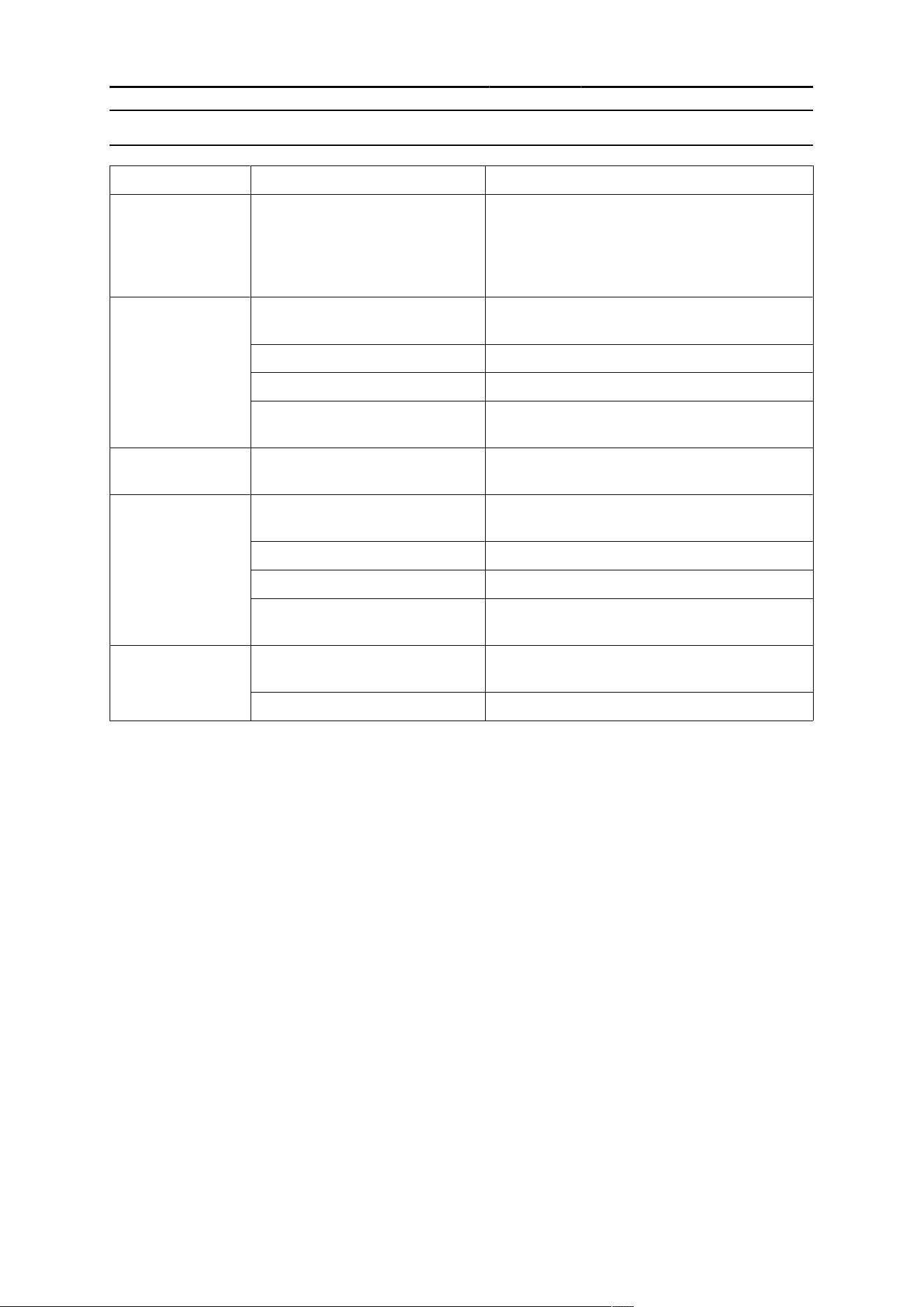
6) To replace the rechargeable battery and external digital dial, remove the three retaining
screws using a Phillips screwdriver.
7) Install the new rechargeable battery and digital dial by using the retaining screws, and
ensure the ADF is plugged into the battery.
5.6 Cleaning the equipment
NOTE!
Do not use strong cleaning solutions.
1) Clean helmet by wiping with a soft, dry cloth.
2) Clean the cartridge surfaces regularly.
6 TROUBLESHOOTING
0448 599 001
- 23 -
© ESAB AB 2026
6TROUBLESHOOTING
6 TROUBLESHOOTING
Type of fault Possible cause Corrective action
Irregular darkening
or dimming
Wrong position of the headgear Make sure the fore/aft adjustment to the
headgear is set to the same position on both
sides of the headgear. This ensures the
correct and equal distance of the
Auto-Darkeing Filter (ADF) to the user’s eyes.
The ADF does not
darken or flicker
The front cover lens is soiled or
damaged
Change the cover lens.
Sensors are soiled Clean the surface of the sensor.
Welding current is too low Increase the sensitivity level.
Problem with battery Check the battery and verify it is in good
condition. Refer to "Charging the battery".
Slow response The operating temperature is
too low
Do not use at temperatures below -5 °C or 23
°F.
Poor vision Front / inside cover lens and/or
the filter is soiled
Change lens.
Insufficient ambient light Increase ambient light.
Shade number is incorrectly set Reset the shade number.
The protective film is still on the
outer cover lens
Ensure the protective film has been removed
from the outer cover lens before first use.
Welding helmet
does not feel
secure
Headgear is not properly
adjusted
Readjust the headgear.
Headgear is damaged Replace the headgear.
APPENDIX
0448 599 001
- 24 -
© ESAB AB 2026
7APPENDIX
APPENDIX
SPARE PARTS
Item Description Part number
1 Sentinel A70PRO Outer cover lens retainer 0700900702
2 Sentinel A70PRO Outer cover lens 0700900703
3 Sentinel A70PRO ADF flip-up shell 0700900704
4 Sentinel A70PRO ADF (digital dial and battery not included) 0700900705
Sentinel A70PRO ADF external digital dial and battery assembly
(with USB-C cable)
0700900706
5 Sentinel A70PRO inner cover lens 0700900707
6 Sentinel A70PRO LED work light cover lens 0700900708
7 Sentinel A70PRO LED light kit (with USB-C cable) 0700900709
8 Sentinel A70PRO Grind protective lens 0700900710
9 Sentinel A70PRO main shell 0700900711
10 Sentinel A70PRO headgear 0700900713
Sentinel A70PRO LED work light power kit 0700900714
Sentinel A70PRO FR rear head and shoulder cover (FR) 0700900716
Sentinel A70PRO split leather rear head and shoulder cover
(optional)
0700900717
Sentinel A70PRO front neck protector (FR) 0700900718

APPENDIX
0448 599 001
- 25 -
© ESAB AB 2026
Item Description Part number
Sentinel A70PRO split leather front neck and chest protector
(optional)
0700900719
Sentinel A70PRO Hard Hat Adapter for Slotted Caps 0700900722

ESAB AB ESAB Corporation ESAB Holdings Ltd
Lindholmsallén 9 2800 Airport Road 322 High Holborn
Box 8004 Denton, TX 76207 WC1V 7PB
402 77 Gothenburg USA London, Great Britain
Sweden Phone +1 800 378 8123 Phone +44 (0) 1992 768515
Phone +46 (0) 31 50 90 00
For contact information visit esab.com
manuals.esab.com