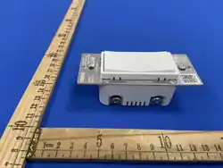
SWITCH-ZW
In-Wall Smart Paddle Switch
Z-Wave 800 Long Range · 908.42 MHz · S2 Security · SmartStart
I N S T A L L A T I O N M A N U A L
V0000785 · © 2026 Versa Wireless Inc.
Specicaons
Input voltage 125 VAC, 60 Hz
Frequency 908.42 MHz (Z-Wave US)
Range
Up to 1300 / direct-to-controller (LR) ·
3302/ (1002m) per hop (mesh)
Tungsten / INC / ballast /
LED
1250 W (10 A) max
GP / resisve 1875 W (15 A) max
Motor load 1/2 HP max
Wiring Single-pole or 3-way; neutral required
Wire Copper only, 14 AWG or larger, 80 °C min
Terminal torque 12 lbf-in (14 kgf-cm)
Operang temp. 32–104 °F (0–40 °C)
Use
Indoor installaAon only, dry locaAon — see
Safety & Warnings
Lisng
ETL Listed — UL 60730-1 · CSA E60730-
1:2015 · Intertek 5030071
FCC ID 2AD9XSWITCH-ZW
Version
1.0 (Z-Wave SDK 7.24.1, Z-Wave version
8.2)
Warranty 2 years
Features
• In-wall on/oK — single-pole or 3-way
• Z-Wave 800 Long Range, S2 security, SmartStart
• Central Scene support (2-tap each paddle)
• Restores state a/er power failure
• Built-in Z-Wave repeater
• Works with any Z-Wave cerAMed hub
LED indicator
State Meaning
Solid blue Switch status (see parameter 2)
Blue Nashing Inclusion or exclusion in progress
Green solid 2 s Inclusion or exclusion success
Red solid 2 s Inclusion or exclusion failed
Green Nashing 3× Parameter changed successfully
Red Nashing 3× Parameter change failed
Purple Nashing Factory reset in progress
Purple solid 2 s Factory reset complete
B E F O R E Y O U I N S T A L L
⚠ TURN OFF the breaker before removing the wall plate. Verify
with a non-contact voltage tester. Lighng loads only — see Safety
& Warnings for the full list of loads this switch must not control.
You will need
• Phillips & Nat-blade screwdrivers, wire stripper, voltage tester
• Single-gang wall box, 2-3/4″ min depth; 14 AWG or larger
copper wire
Idenfy wires
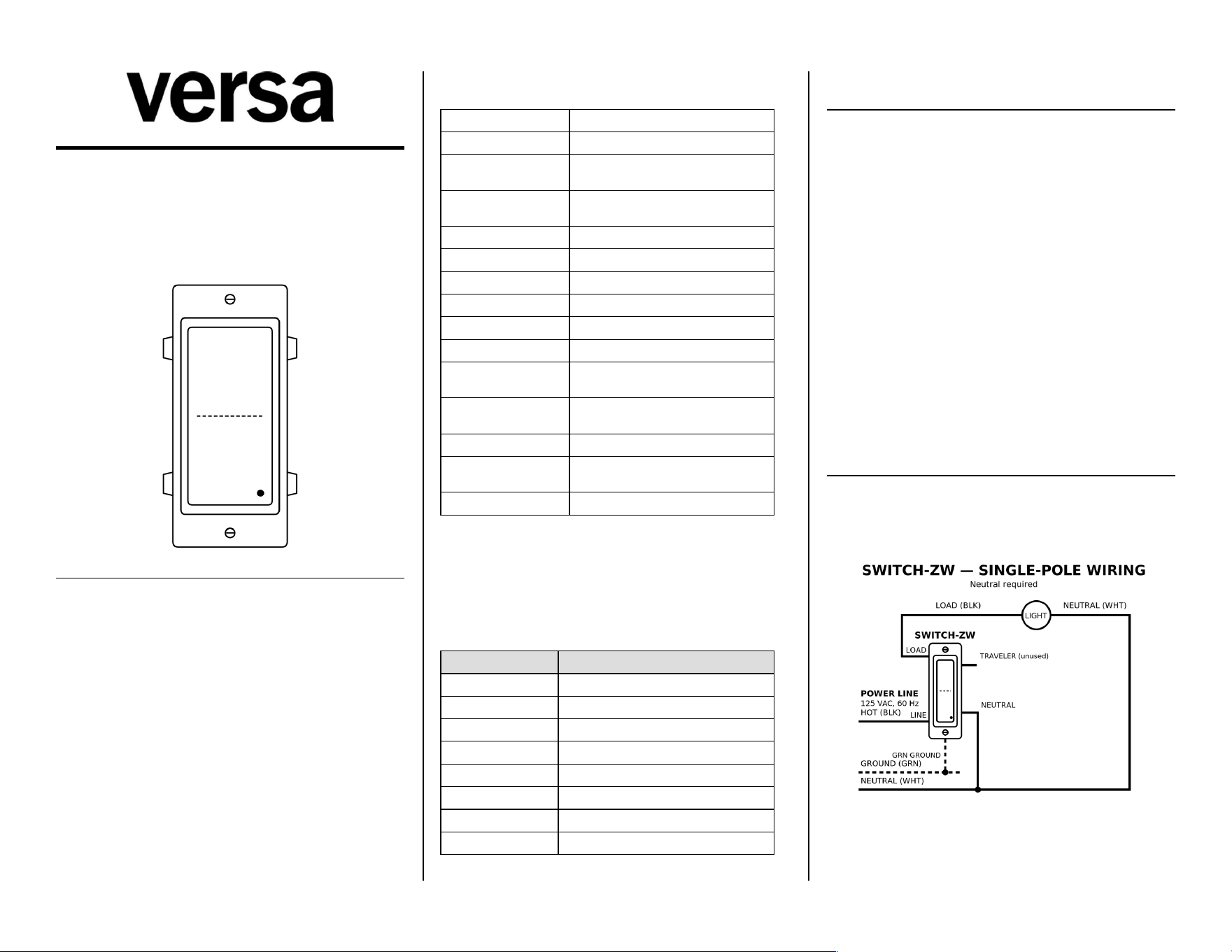
• Line (black) → LINE terminal
• Load (black/red) → LOAD terminal — line and load can't be
swapped
• Neutral (white) → NEUTRAL terminal — required
• Ground (bare/green) → GROUND terminal (green, top of the
switch)
• Traveler (3-way only, red) → TRAVELER terminal
Install wires into the terminals
Strip each wire 5/8″ (16 mm). Loosen the screw terminal counter-
clockwise a few turns unAl you feel resistance. There are two holes
behind each terminal — insert the straight wire into one of them
and Aghten the screw clockwise to 12 lbf-in (14 kgf-cm). Don't wrap
wires around the screws, and don't use power tools.
W I R I N G — S I N G L E - P O L E
Power OFF. Ground → GROUND, Neutral → NEUTRAL, Line → LINE,
Load → LOAD. The neutral is usually a bundle — land the supplied
white jumper from that bundle on the NEUTRAL terminal. Tug-test
each wire, fold the wires back into the box, mount the switch, then
restore power.
Doc: V0000785
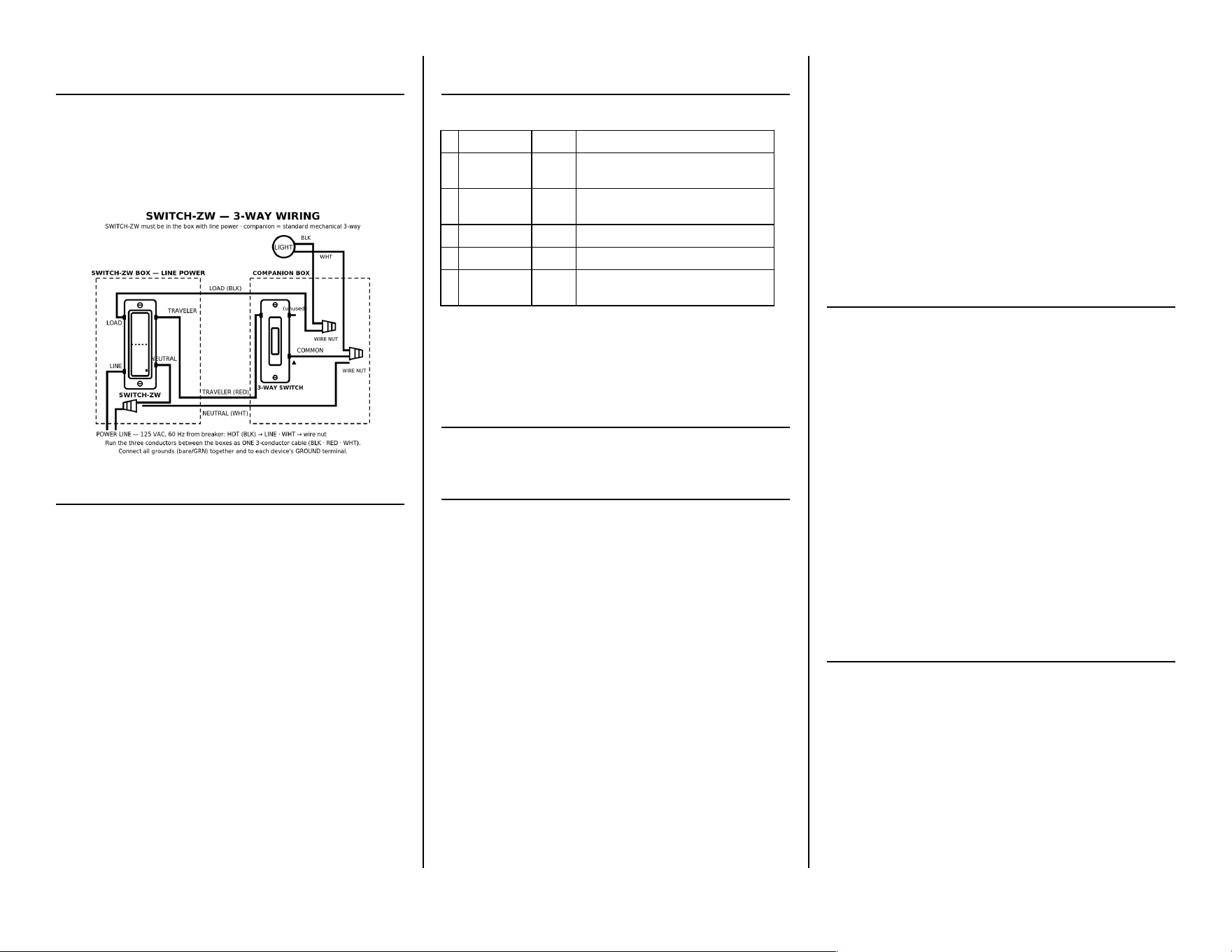
W I R I N G — 3 - W A Y
SWITCH-ZW must be installed in the box that has line power. The
companion must be a standard mechanical 3-way switch. Run the
traveler (red) from the TRAVELER terminal to a traveler screw on the
companion, and run a white conductor from the companion's
COMMON screw back into the neutral bundle. The companion
makes and breaks that loop only — no load current passes through
it.
If your wiring doesn't match, stop and consult an electrician.
Z - W A V E N E T W O R K S E T U P
Add the device (inclusion)
Set your controller to add a device. Press the TOP paddle 3× quickly
— the blue LED Nashes. Green 2 s = success. Red 2 s = failed, retry.
Remove the device (exclusion)
Set your controller to remove a device. Press the BOTTOM paddle 3×
quickly.
Factory reset
Press the BOTTOM paddle 2× quickly, then hold for at least 10
seconds. Purple Nashing → solid purple 2 s = reset complete.
SmartStart
Scan the Z-Wave QR code on the metal yoke under the paddle with a
SmartStart-capable controller. The full DSK is printed on the carton.
The switch is added automaAcally within 10 minutes.
First power-up
A switch that has never joined a network powers up with the relay
OFF and the blue LED on. A switch that was already in a network
returns to its last state with a so/ start.
Associaon groups
Group 1 — Lifeline (5 nodes, Binary Switch Report)
Group 2 — Single Press (5 nodes, sends Basic Set on a local paddle
press)
P A R A M E T E R S E T T I N G S
Set from your hub. The LED Nashes green 3× for success, red 3× for
failure.
# Parameter Default Values
1
BuXon
FuncAon
0
0=Top ON/Bot OFF (def), 1=Top OFF/Bot
ON, 2=both toggle
2 LED Indicator 0
0=paddle posiAon (def), 1=relay, 2=oK,
3=on
4 Auto Turn-OK 0 Minutes 1–65535. 0=disabled.
6 Auto Turn-On 0 Minutes 1–65535. 0=disabled.
8
Restore A/er
Power Fail
2 0=oK, 1=on, 2=last state (def)
Paddle funcons
• Top 1×: ON · BoXom 1×: OFF (Param 1)
• Top 2×: Scene 1 · BoXom 2×: Scene 2
• Top 3×: include · BoXom 3×: exclude
• Top 8×: cycle Param 1 · BoXom 8×: cycle Param 8
• BoXom 10×: cycle Param 2
Z - W A V E I N T E R O P E R A B I L I T Y
Works with any Z-Wave cerAMed network. All non-baXery nodes act
as repeaters. SWITCH-ZW supports Lifeline (group 1); most
controllers conMgure this automaAcally during inclusion.
C E R T I F I C A T I O N S & C O M P L I A N C E
• ETL Listed (c-US) — UL 60730-1 · CSA E60730-1:2015 · Intertek
5030071
• FCC Part 15 Class B · FCC ID: 2AD9XSWITCH-ZW
• Z-Wave Plus cerAMed · Z-Wave 800 Long Range, SDK 7.24.1
FCC compliance
This device complies with Part 15 of the FCC Rules. OperaAon is
subject to: (1) this device may not cause harmful interference; (2)
this device must accept any interference received, including
interference that may cause undesired operaAon. Changes or
modiMcaAons not expressly approved by the party responsible for
compliance could void the user's authority to operate the
equipment.
FCC Class B
This equipment has been tested and complies with Part 15 Class B
limits, providing reasonable protecAon against interference in
residenAal installaAons. If interference occurs (verify by powering oK
and on), try:
• Reorient or relocate the receiving antenna.
• Increase separaAon between equipment and receiver.
• Connect to a circuit diKerent from the receiver.
• Consult a qualiMed radio/TV technician.
RF exposure
This equipment complies with FCC radiaAon exposure limits set forth
for an uncontrolled environment. Install and operate with a
minimum distance of 20 cm between the radiator and any person.
S A F E T Y & W A R N I N G S
⚠ RISK OF FIRE / ELECTRIC SHOCK / BURNS
TURN OFF the breaker before installaAon. Verify with a voltage
tester before touching any wires.
Do not exceed 1875 W (15 A) general purpose or resisAve, 1250 W
(10 A) tungsten/incandescent/ballast/LED, or 1/2 HP motor. Use
copper conductors only. DO NOT use to control receptacles,
tube/Nuorescent Mxtures, transformer-supplied Mxtures, heat lamps,
or sun lamps.
Medical equipment
Do not use this switch to control medical or life-support equipment.
Controlling appliances
Use extreme cauAon with appliances. Schedules, automaAons, or
network errors may cycle a device unintenAonally. Do not include
appliance-controlling devices in groups or scenes, and do not use Z-
Wave to control electric heaters or any device that could become
hazardous if unaXended.
Cauon — please read
Install per the NaAonal Electrical Code and local regulaAons. Where
required by code, installaAon must be performed by a qualiMed,
licensed electrician. If unsure, consult an electrician.
W A R R A N T Y
Versa Wireless products are warranted free from manufacturing
defects for two years from the original date of consumer purchase.
Limited to repair or replacement; does not cover consequenAal or
incidental damage. This warranty is in lieu of all other warranAes
expressed or implied. Some states do not allow such limitaAons, so
they may not apply to you. You may have other rights that vary by
state.
versawireless.com
Doc: V0000785