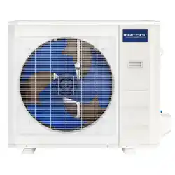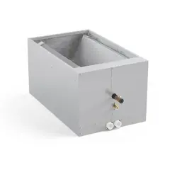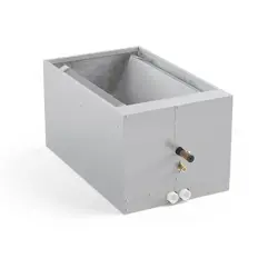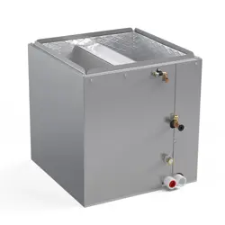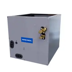
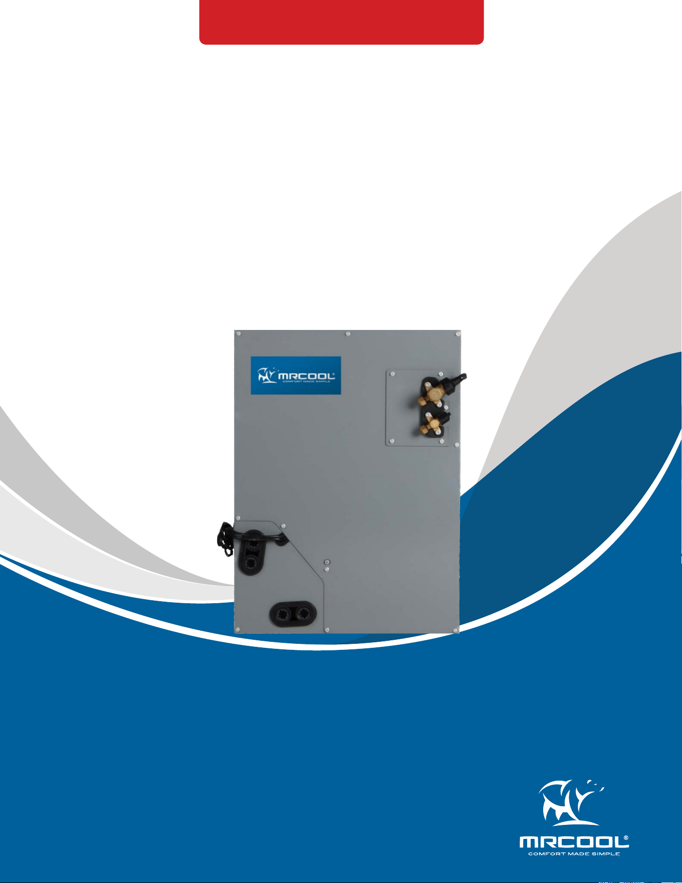
MODELS:
Read this manual carefully before installation and keep it where
the operator can easily nd it for future reference.
Due to updates and constantly improving performance, the
information and instructions within this manual are subject to
change without notice.
Version Date: June 19, 2025
Please visit www.mrcool.com/documentation
to ensure you have the latest version of this manual.
MCMP*OTB
This product utilizes R-454B refrigerant
MRCOOL®
A-Coil
Service Manual

mrcool.com1
CONTENTS
SAFETY ............................................................................................................................... 2
SYSTEM OVERVIEW ........................................................................................................... 9
2.1 System Introduction ............................................................................................ 9
2.2 Dimensional Drawings ........................................................................................ 9
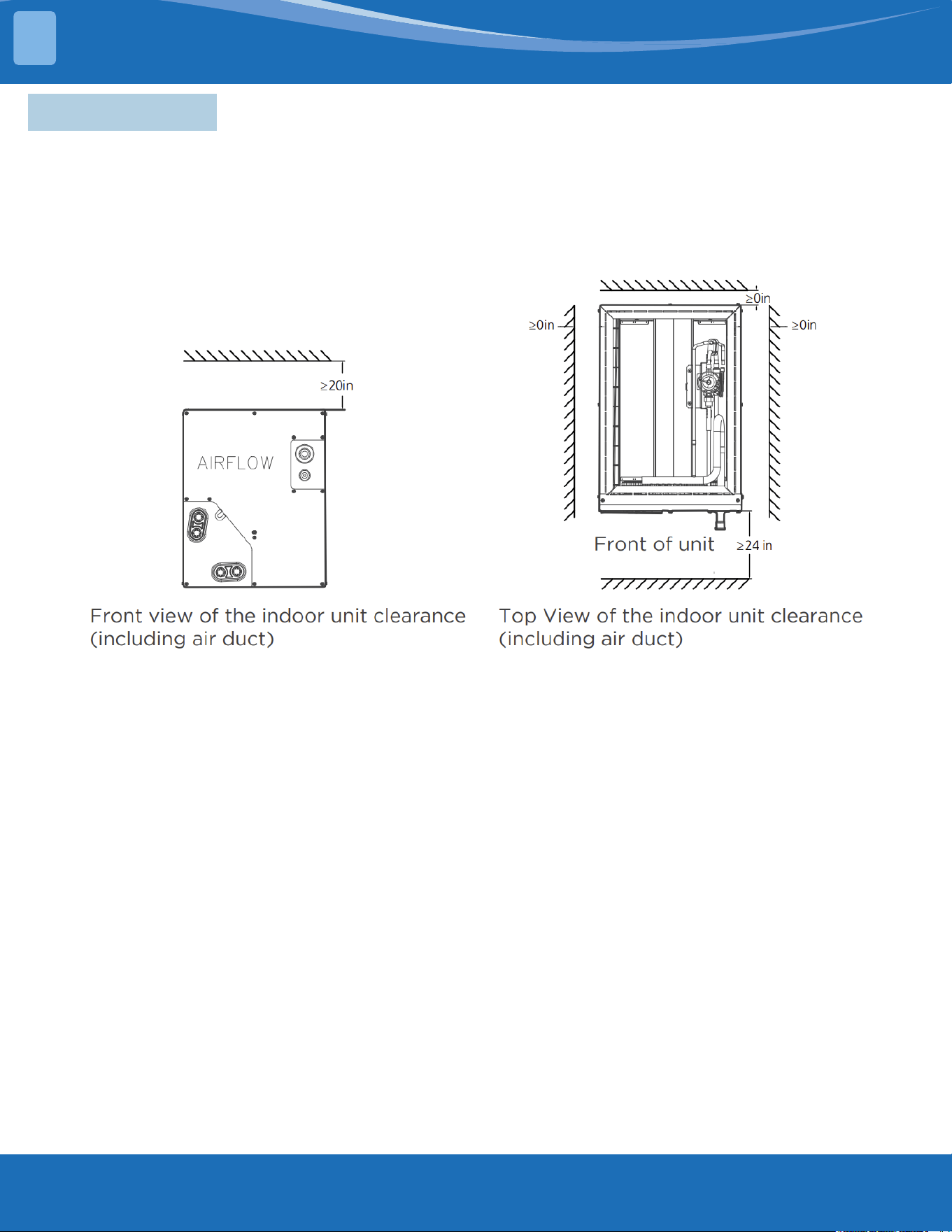
2.3 Clearances .......................................................................................................... 11
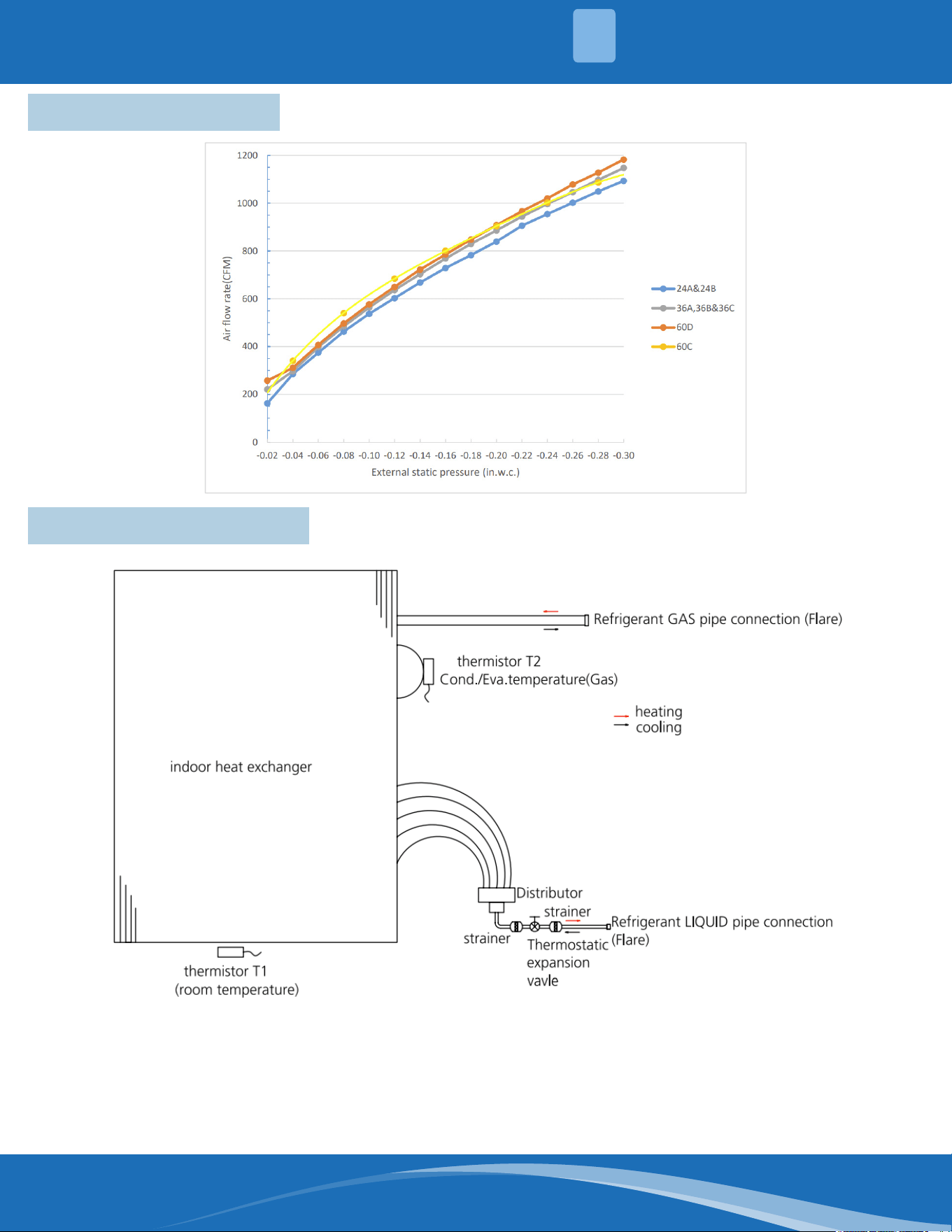
2.4 Fan Performance ............................................................................................... 12
2.5 Refrigerant Diagram ......................................................................................... 12
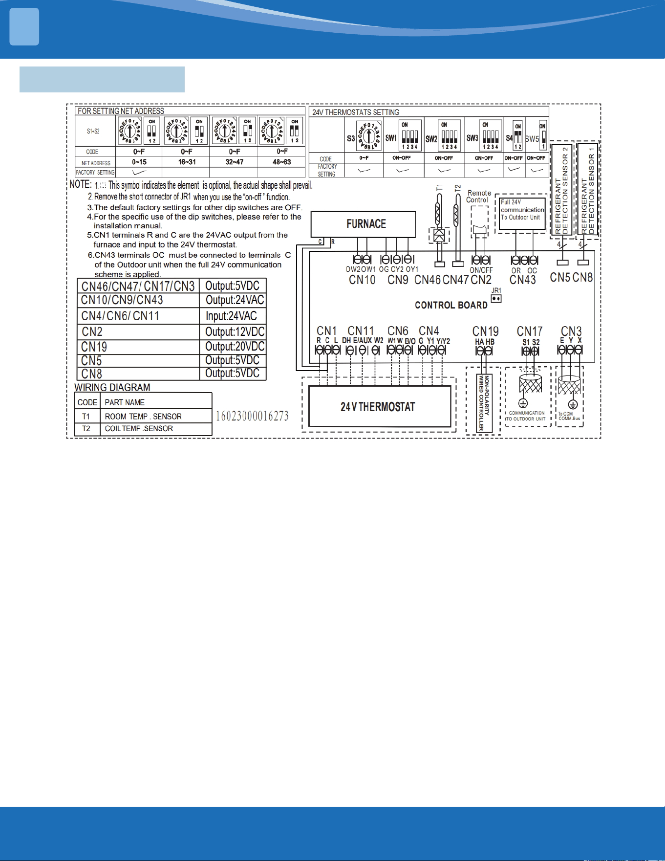
2.6 Wiring Diagram .................................................................................................. 13
2.7 DIP Switch Denitions ....................................................................................... 14
INSTALLATION ................................................................................................................ 18
3.1 Location Selection ............................................................................................. 18
3.2 Indoor Unit Installation (A-COIL) ..................................................................... 18
3.3 Installation of MINI Interface ........................................................................... 21
3.4 Refrigerant Pipe Installation ............................................................................ 22
3.5 Insulation ............................................................................................................ 23
3.6 Electrical Wiring ................................................................................................. 34
PRODUCT FEATURES ...................................................................................................... 26
4.1 Wiring .................................................................................................................. 26
4.2 Controls .............................................................................................................. 28
4.3 Safety Features (NON-24V Control) ................................................................. 30
TROUBLESHOOTING ...................................................................................................... 33
5.1 Safety Caution .................................................................................................... 33
5.2 Error Display (Indoor Unit) ............................................................................... 34
5.3 Information Inquiry & Setting .......................................................................... 35
5.4 Error Diagnosis Without Error Code ................................................................ 40
5.5 Quick Maintenance by Error Code .................................................................. 47
5.6 Troubleshooting by Error Code ....................................................................... 48
5.7 Check Procedures .............................................................................................. 68
TEMPERATURE SENSOR RESISTANCE TABLE ............................................................... 69
SYSTEM PRESSURE TABLE .............................................................................................. 71
Contents
1
2
3
4
5
6
7
mrcool.com 2 2
SAFETY
1
Incorrect usage may cause serious damage or injury.
The symbols below are used throughout this manual to indicate instructions that should be
followed closely or actions that should be avoided to prevent death, injury, and/or property
damage.
Safety Precautions
CAUTION
Indicates the possibility of personal injury or loss of life.
Indicates the possibility of property damage or serious
consequences.
Read Before Using
WARNING
WARNING FOR PRODUCT INSTALLATION
INSTALLATION MUST BE PERFORMED BY AN AUTHORIZED DEALER OR SPECIALIST. DEFECTIVE
INSTALLATION CAN CAUSE WATER LEAKAGE, ELECTRICAL SHOCK, OR FIRE.
****ELECTRICAL WORK MUST BE COMPLETED BY A QUALIFIED ELECTRICAL TECHNICIAN****
DO NOT install the unit in a location that may be exposed to combustible gas leaks. If
combustiblegasaccumulatesaroundtheunit,itcouldcausere.
DO NOT turn on the power until the installation and all work has been completed.
1. Installation must be performed according to the installation instructions. Improper installation could cause
water leakage, electrical shock, or re.
2. Contact an authorized service technician for repair or maintenance of this unit.
3. This appliance must be installed in accordance with national wiring regulations.
4. Only use the included accessories, parts, and specied parts for installation. Using non-standard parts can
cause water leakage, electrical shock, re, and/or failure of the unit.
5. Install the unit in a rm location that can support the unit’s weight. If the location cannot support the unit’s
weight, or the installation is not done properly, the unit may drop and cause serious injury and damage.
6. Install the drainage piping according to the instructions in this manual. Improper drainage could cause
water damage to your home and/or property.
7. When moving or relocating the air conditioner, consult experienced service technicians for disconnection
and re-installation of the unit.
8. For detailed information of how to install the indoor and outdoor units to their respective supports, please
refer to the indoor unit installation and outdoor unit installation sections of this manual.
9. USB device access, replacement, and maintenance operations must be carried out by professional sta.
WARNING FOR CLEANING & MAINTENANCE
1. DO NOT clean the unit with excessive amounts of water.
2. DO NOT clean the unit with combustible cleaning agents, as these could cause deformation and/or re.
3. Turn o the device and disconnect the power before cleaning. Failure to do this could result in electrical
shock.
TAKE NOTE OF FUSE SPECIFICATIONS
• The unit’s circuit board (PCB) is designed with a fuse to provide over-current protection.
• The specications of the fuse are printed on the circuit board, examples of such are T5A/250VAC and
T10A/250VAC.
Note: Only a blast-proof ceramic fuse can be used.
mrcool.com3
SAFETY
1
WARNING FOR PRODUCT USE
DO NOT insertngers,rods,orotherobjectsintotheairinletoroutlet.Thiscouldcauseinjury,
since the fan may be rotating at high speeds.
DO NOT useammablesprayssuchashairspray,lacquerorpaintneartheunit,asthiscould
causereand/oranexplosion.
DO NOT operate the unit in places near or around combustible gases. Emitted gas may collect
around the unit and cause an explosion.
DO NOT allow children to play with the appliance. Children must be supervised around
the unit at all times.
DO NOT operate the unit in a room where it could be exposed to excessive amounts of water,
such as a bathroom or laundry room. Exposure to excessive water amounts can cause the
electrical components to short circuit.
DO NOT exposeyourbodydirectlytodirectcoolairowfromtheunitforaprolongedperiod
of time.
1. If the unit operates abnormally (emits strange noises or a burning smell), immediately turn o the unit
and disconnect the power in order to avoid electric shock, re, and/or injury. Call your local dealer, or
MRCOOL® tech support at (270) 366-0457, for further assistance.
2. If the air conditioner is used together with burners or other heating devices, thoroughly ventilate the room
in order to avoid an oxygen deciency.
3. In certain functional environments (such as kitchens and server rooms etc.), the use of specially designed
air-conditioning units is highly recommended.
4. This appliance is not intended for use by persons(including children) with reduced physical, sensory or
mental capabilities, or lack of experience and knowledge, unless they have been given supervision or
instruction concerning use of the appliance by a person responsible for their safety. Children should be
supervised to ensure that they do not play with the appliance.
5. Turn o the unit and disconnect the power before performing any cleaning, installation, or repairing.
Failure to do so can cause electric shock.
ELECTRICAL WARNINGS
****ELECTRICAL WORK MUST BE COMPLETED BY A QUALIFIED ELECTRICAL TECHNICIAN****
DO NOT sharethepowersupplywithotherappliances.Animproperorinsucientpower
supplycouldcausereand/orelectricalshock.
1. Only use the specied wire. If the wire is damaged, it must be replaced by the manufacturer, its service
agent or similarly qualied persons in order to avoid a hazard.
2. The product must be properly grounded during installation or electrical shock could occur.
3. Appropriate wiring standards, regulations, and the installation manual must be followed for all electrical
work.
4. If connecting power to xed wiring, an all-pole disconnection device must be incorporated in the xed
wiring in accordance with the wiring rules and must meet the following requirements: at least 3 mm of
clearances in all poles, a leakage current that may exceed 10 mA, and a residual current device (RCD)
having a rated residual operating current not exceeding 30 mA.
5. Connect cables tightly and clamp them securely to prevent external forces from damaging the terminal.
CAUTION
DO NOT allow the air conditioner to operate for extended periods of time with the doors or
windows open, or in very high humidity.
DO NOT operate the air conditioner with wet hands, as this could cause electric shock.
DO NOT use device for any other purpose than its intended use.
DO NOT climbontoorplaceobjectsontopoftheoutdoorunit.
1. Make sure that water condensation can drain smoothly and unhindered from the unit.
2. Turn o the unit and disconnect the power if the unit will not be used for an extended period of time.
3. Turn o and unplug the unit during storms.
mrcool.com 4
4
SAFETY
1
FLAMMABLE REFRIGERANT WARNINGS
1. The installation of pipe-work should be kept to a minimum and should be protected from physical damage.
2. Refrigerant pipes should comply with national gas regulations.
3. All mechanical connections and ventilation openings should be kept clear of obstruction.
4. Utilize proper disposal processes based on national regulations.
5. Any person involved with working on or breaking into a refrigerant circuit should hold a current valid
certicate from an industry-accredited assessment authority, which authorizes their competence to handle
refrigerants safely in accordance with an industry recognized assessment specication.
6. Maintenance and repair requiring the assistance of other skilled personnel shall be carried out under the
supervision of the person competent in the use of ammable refrigerants.
7. Do not use any means to accelerate the defrosting process or to clean, other than those recommended by
the manufacturer.
8. The appliance shall be stored in a room without continuously operating ignition sources (for example: open
ames, an operating gas appliance, or an operating electric heater).
9. Do not allow foreign matter (oil, water, etc.) to enter the piping, and securely seal the opening by pinching,
taping, etc.
10. Do not pierce or burn.
11. Refrigerants may not contain an odor.
12. Working procedures that aect safety should only be carried out by competent persons.
13. The unit should be stored in a well-ventilated area where the room size corresponds to the room area as
specic for operation, and should be stored so as to prevent potential mechanical damage from occurring.
14. Joints should be tested with detection equipment with a capability of 5 g/year of refrigerant or better, with
the equipment in standstill and under operation or under a pressure of at least these standstill or operation
conditions after installation. Detachable joints should NOT be used in the indoor side of the unit (brazed,
welded joint could be used).
15. A leak detection system is installed. The unit must be powered except for service. For units with a refrigerant
sensor, the indoor unit will display an error code and emit a buzzing sound, the compressor of the outdoor
unit will immediately stop, and the indoor fan will start running. The service life of the refrigerant sensor
is 15 years. When the refrigerant sensor malfunctions, the indoor unit will display the error code "FHCC".
The refrigerant sensor cannot be repaired and can only be replaced by the manufacturer. It should only be
replaced with the sensor specied by the manufacturer.
16. When a ammable refrigerant is used, the requirements for installation space of the appliance and/or
ventilation requirements are determined according to:
• The mass charge amount (M) used in the unit.
• The installation location.
• The type of ventilation of the location of the unit.
• Piping material, pipe routing, and installation must include protection from physical damage in
operation and service. This must be in compliance with local codes and standards, such as ASHRAE
15, IAPMO Uniform Mechanical Code, ICC International Mechanical Code, or CSA B52. All eld joints
must be accessible for inspection prior to being covered or enclosed.
• Protection devices, piping and ttings must be protected as much as possible against adverse
environmental eects. For example, against the danger of water collecting and freezing in relief pipes
or against accumulation of dirt or debris.
ELECTRICAL WARNINGS
Improper electrical connections could overheat, causing re and/or electrical shock.
5. All electrical connections must be made according to the Electrical Connection Diagram located on the
panels of the indoor and outdoor units.
6. All wiring must be properly arranged to ensure that the control board cover can close properly. If the
control board cover is not properly closed, it can lead to corrosion and cause the connection points on the
terminal to heat up, catch re, or cause electrical shock.
7. Disconnection must be incorporated in the xed wiring in accordance with the wiring rules.
mrcool.com5
SAFETY
1
FLAMMABLE REFRIGERANT WARNINGS
• Piping in refrigeration systems must be designed and installed to minimize the likelihood of hydraulic
shock, resulting in damage from the system.
• Steel pipes and components must be protected against corrosion with a rust-proof coating before
applying insulation.
• Precautions must be taken against excessive vibration or movement of the unit.
• The minimum oor area of the room must be mentioned in the form of a table or a single gure
without reference to a formula.
17. After completion of eld piping for split systems, the eld pipework should be pressure tested with an inert
gas and then vacuum tested prior to refrigerant charging, according to the following requirements:
• The minimum test pressure for the low side of the system should be the low side design pressure and
the minimum test pressure for the high side of the system should be the high side design pressure,
unless the high side of the system cannot be isolated from the low side of the system in which case the
entire system should not be pressure tested to the low side design pressure.
• The test pressure after removal of pressure source shall be maintained for at least 1 hour with no
decrease of pressure indicated by the test gauge, with test gauge resolution not exceeding 5% of the
test pressure.
18. Prior to beginning work on systems containing ammable refrigerants, safety checks are necessary
to ensure that the risk of ignition is minimized. For repairs to the refrigerating system, the following
precautions shall be complied with prior to conducting work on the system.
19. Work should be undertaken under a controlled procedure so as to minimize the risk of a ammable gas or
vapor being present while the work is being performed.
20. All maintenance sta and others working in the local area should be instructed on the nature of work being
carried out. Avoid work in conned spaces.
21. The area should be checked with an appropriate refrigerant detector prior to and during work, to ensure the
technician is aware of potentially ammable atmospheres. Ensure that the leak detection equipment being
used is suitable for use with ammable refrigerants, i.e. no sparking, adequately sealed, or intrinsically safe.
22. If any hot work is to be conducted on the refrigeration equipment or any associated parts, appropriate re
extinguishing equipment should be on site and readily available. Have a dry power or CO2 re extinguisher
adjacent to the charging area.
23. No person carrying out work in relation to a refrigerating system which involves exposing any pipe work
should use any sources of ignition in such a manner that it may lead to the risk of re or explosion. All
possible ignition sources, including cigarette smoking, should be kept suciently far away from the site
of installation, repairing, removing, and disposal, during which refrigerant can possibly be released to the
surrounding space. Prior to work taking place, the area around the equipment is to be surveyed to make
sure that there are no ammable hazards or ignition risks. "No Smoking" signs should be displayed.
24. Ensure that the area is in the open or that it is adequately ventilated before breaking into the system or
conducting any hot work. A degree of ventilation shall continue during the period that the work is carried
out. The ventilation should safely disperse any released refrigerant and preferably expel it externally into the
atmosphere.
23. Where electrical components are being changed, they shall be t for the purpose and to the correct
specication. At all times the manufacturer's maintenance ad service guidelines shall be followed. If in
doubt, consult the manufacturer's technical department for assistance. The following checks should be
applied to installations using ammable refrigerants:
• the actual refrigerant charge is in accordance with the room size within which the refrigerant containing
parts are installed;
• the ventilation machinery and outlets are operating adequately and are not obstructed;
• if an indirect refrigerating circuit is being used, the secondary circuits should be checked for the
presence of refrigerant;
• marking to the equipment continues to be visible and legible, marking and signs that are illegible
should be corrected;
• refrigerant pipe or components are installed in a position where they are unlikely to be exposed to
any substance which may corrode refrigerant containing components, unless the components are
constructed of materials which are inherently resistant to or protected against corrosion.
mrcool.com 6
6
SAFETY
1
FLAMMABLE REFRIGERANT WARNINGS
24. Repair and maintenance to electrical components shall include initial safety checks and component
inspection procedures. If a fault exists that could compromise safety, then no electrical supply shall be
connected to the circuit until it is satisfactorily dealt with. If the fault cannot be corrected immediately but it
is necessary to continue operation, an adequate temporary solution should be used.
25. Initial safety checks should include:
• that capacitors are discharged: this should be done in a safe manner to avoid the possibility of sparking;
• that there are no live electrical components and wiring are exposed while charging, recovering, or
purging the system;
• that there is continuity of earth bonding.
26. Sealed electrical components should be replaced if damaged.
27. Intrinsically safe components should be replaced if damaged.
28. Check that wiring will not be subject to wear, corrosion, excessive pressure, vibration, sharp edges, or
any other adverse environmental eects. The check shall also take into account the eects of aging or
continual vibration from sources such as compressors or fans.
29. Under no circumstances should potential sources of ignition be used in the search for or detection of
refrigerant leaks. A halide torch (or any other detector using a naked ame) should not be used. The
following leak detection methods are deemed acceptable for refrigerant systems. Electronic leak detectors
may be used to detect refrigerant leaks but, in the case of ammable refrigerants, the sensitivity may
not be adequate, or may need re-calibration. (Detection equipment shall be calibrated in a refrigerant-
free area.) Ensure that the detector is not a potential source of ignition and is suitable for the refrigerant
used. Leak detection equipment shall be set at a percentage of the LFL of the refrigerant and should
be calibrated to the refrigerant employed, and the appropriate percentage of gas (25% minimum) is
conrmed. Leak detection uids are also suitable for use with most refrigerants but the use of detergents
containing chlorine may react with the refrigerant and corrode the copper work. Examples of leak
detection uids are the bubble method, uorescent method agents, etc. If a leak is suspected, all naked
ames should be removed/extinguished. If a leakage of refrigerant is found which requires brazing, all of
the refrigerant should be recovered from the system, or isolated (by means of shut-o valves) in a part of
the system remote from the leak. See the following instructions of removal of refrigerant.
30. When breaking into the refrigerant circuit to make repairs, or for any other purpose, conventional
procedures should be used. However, for ammable refrigerants, it is even more vital to follow best
practice. The following procedure should be adhered to:
• safely remove refrigerant following local and national regulations;
• evacuate;
• purge the circuit with inert gas;
• evacuate;
• continuously ush or purge with inert gas when using ame to open circuit;
• open the circuit
31. The refrigerant charge should be recovered into the correct recovery cylinders if venting is not allowed by
local and national codes. For units containing ammable refrigerants, the system should be purged with
oxygen-free nitrogen to render the appliance safe for ammable refrigerants. This process might need to
be repeated several times. Compressed air or oxygen shall not be used for purging refrigerant systems.
For appliances containing ammable refrigerants, refrigerant purging should be achieved by breaking the
vacuum in the system with oxygen-free nitrogen and continuing to ll the working pressure is achieved,
then venting to atmosphere, and nally pulling down to a vacuum. This process should be repeated until
no refrigerant is within the system. When the nal oxygen-free nitrogen charge is used, the system should
be vented down to atmospheric pressure to enable work to take place. The outlet for the vacuum pump
should not be close to any potential ignition sources, and ventilation should be available.
32. In addition to conventional charging procedures, the following requirements should be followed:
• Work should be undertaken with appropriate tools only (in case of uncertainty, please consult the
manufacturer of the tools for use with ammable refrigerants)
• Ensure that contamination of dierent refrigerants does not occur when using charging equipment.
Hoses or lines shall be as short as possible to minimize the amount of refrigerant contained in them.
mrcool.com7
FLAMMABLE REFRIGERANT WARNINGS
• Ensure that the refrigeration system is grounded prior to charging the system with refrigerant.
• Label the system when charging is complete (if not already).
• Extreme care should be taken not to overll the refrigeration system.
• Prior to recharging the system, it should be pressure tested with oxygen-free nitrogen (OFN). The
system should be leak-tested on completion of charging but prior to commissioning. A follow-up leak
test shall be carried out prior to leaving the site.
33. Before carrying out this procedure, it is essential that the technician is completely familiar with the
equipment and all its detail. It is good recommended practice that all refrigerants are recovered safely.
Prior to the task being carried out, an oil and refrigerant sample should be taken in case analysis is
required prior to re-use of recovered refrigerant. It is essential that electrical power is available before the
task is commenced.
a. Become familiar with the equipment and its operation.
b. Isolate the system electrically.
c. Before attempting the procedure ensure that:
• mechanical handling equipment is available, if required, for handling refrigerant cylinders;
• all personal protective equipment is available and being used correctly;
• the recovery process is supervised at all times by a competent person;
• recovery equipment and cylinders conform to the appropriate standards
Pump down refrigerant system, if possible.
e. If a vacuum is not possible, make a manifold so that refrigerant can be removed from various parts of
the system.
f. Make sure that the cylinder is situated on the scales before recovery takes place.
g. Start the recovery machine and operate in accordance with instructions.
h. Do not overll cylinders (no more than 80% volume liquid charge).
i. Do not exceed the maximum working pressure of the cylinder, even temporarily.
j. When the cylinders have been lled correctly and the process completed, make sure that the cylinders
and equipment are removed from the site promptly and all isolation valves on the equipment are closed o.
k. Recovered refrigerant should not be charged into another refrigeration system unless it has been
cleaned and checked.
34. Equipment shall be labeled stating that it has been decommissioned and emptied of refrigerant. The label
should be dated and signed. For appliances containing ammable refrigerants, ensure that there are labels
on the equipment stating the equipment contains ammable refrigerant.
35. When removing refrigerant from a system, either for servicing or decommissioning, it is good
recommended practice that all refrigerants are removed safely. When transferring refrigerant into
cylinders, ensure that only appropriate refrigerant recovery cylinders are employed. Ensure that the
correct number of cylinders for holding the total system charge is available. All cylinders to be used should
be designated for the recovered refrigerant and labeled for that refrigerant (i.e. special cylinders for the
recovery of refrigerant). Cylinders shall be complete with pressure-relief valve and associated shut-o
valves in good working order. Empty recovery cylinders are evacuated and, if possible, cooled before
recovery occurs. The recovery equipment should be in good working order with a set of instructions
concerning the equipment that is at hand and should be suitable for the recovery of the ammable
refrigerant. If in doubt, the manufacturer should be consulted. In addition, a set of calibrated weighing
scales should be available and in good working order. Hoses should be complete with leak-free disconnect
couplings and in good condition. The recovered refrigerant should be processed according to local
legislation in the correct recovery cylinder, and the relevant waste transfer note arranged. Do not mix
refrigerants in recovery units and especially not in cylinders.
36. If compressors or compressor oils are to be removed, ensure that they have been evacuated to an
acceptable level to make certain that ammable refrigerant does not remain within the lubricant. The
compressor body should not be heated by an open ame or other ignition sources to accelerate this
process. When oil is drained from a system, it should be carried out safely.
37. An unventilated area where the appliance using ammable refrigerants is installed should be constructed
so that should any refrigerant leak, it will not stagnate so as to create a re or explosion hazard. If
appliances connected via an air duct system to one or more rooms below the ventilation requirements,
SAFETY
1
mrcool.com 8
8
FLAMMABLE REFRIGERANT WARNINGS
that room should never contain potential ignition sources. A ame-producing device may be installed
in the space if the device is provided with an eective ame arrest. Auxiliary devices which may be a
potential ignition source should not be installed in the duct work. Examples of such are hot surfaces with
a temperature exceeding 1292°F (700°C) and electric switching devices. Only auxiliary devices (such as
a certied heater kit) approved by the manufacturer or declared suitable with the refrigerant should be
installed in connecting ductwork. False or drop ceilings may be used as a return air plenum if a refrigerant
detection system is provided in the appliance and any external connections are also provided with a sensor
immediately below the return air plenum duct joint. Refrigerant sensors for refrigerant detection systems
should only be replaced with sensors specied by the manufacturer. A leak detection system is installed.
The unit must be powered except for service.
38. Transport of equipment containing ammable refrigerants should comply with transportation regulations.
39. Marking of equipment using signs should comply with local regulations.
40. Disposal of equipment using ammable refrigerants should comply with national regulations.
41. Storage of equipment/appliances should be in accordance with the manufacturer's instructions.
42. Storage of packed (unsold) equipment should be constructed so that mechanical damage to the equipment
inside the package will not cause a leak of the refrigerant charge. The maximum number of pieces of
equipment permitted to be stored together will be determined by local regulations.
43. During the evacuation test, after achieving a vacuum level specied in the manual or less, the refrigeration
system shall be isolated from the vacuum pump and the pressure shall not rise above 1500 microns within
10 minutes. The vacuum pressure level should be specied in the manual, and should be the lessor of 500
microns of the value required for compliance with national and local codes and standards, which may vary
between residential, commercial, and industrial buildings.
• Field-made refrigerant joints indoors should be tightness-tested according to the following
requirements: the test method should have a sensitivity of 5 grams per year of refrigerant or better
under a pressure of at least 0.25 times the maximum allowable pressure. No leak should be detected.
• Any servicing should be performed only as recommended by MRCOOL®.
43. Any maintenance, service, or repair operations must be performed by qualied personnel. Every working
procedure that aects safety should only be carried out by competent persons that are both trained and
certied. The training of these procedures should be carried out by national training organizations or
manufacturers that are accredited to teach the relevant national competency standards that may be set in
legislation. All training should follow the ANNEX HH requirements of UL 60334-2-40 4th Edition.
Examples of such working procedures are:
• breaking into a refrigerant circuit
• opening of sealed components
• opening of ventilated enclosures
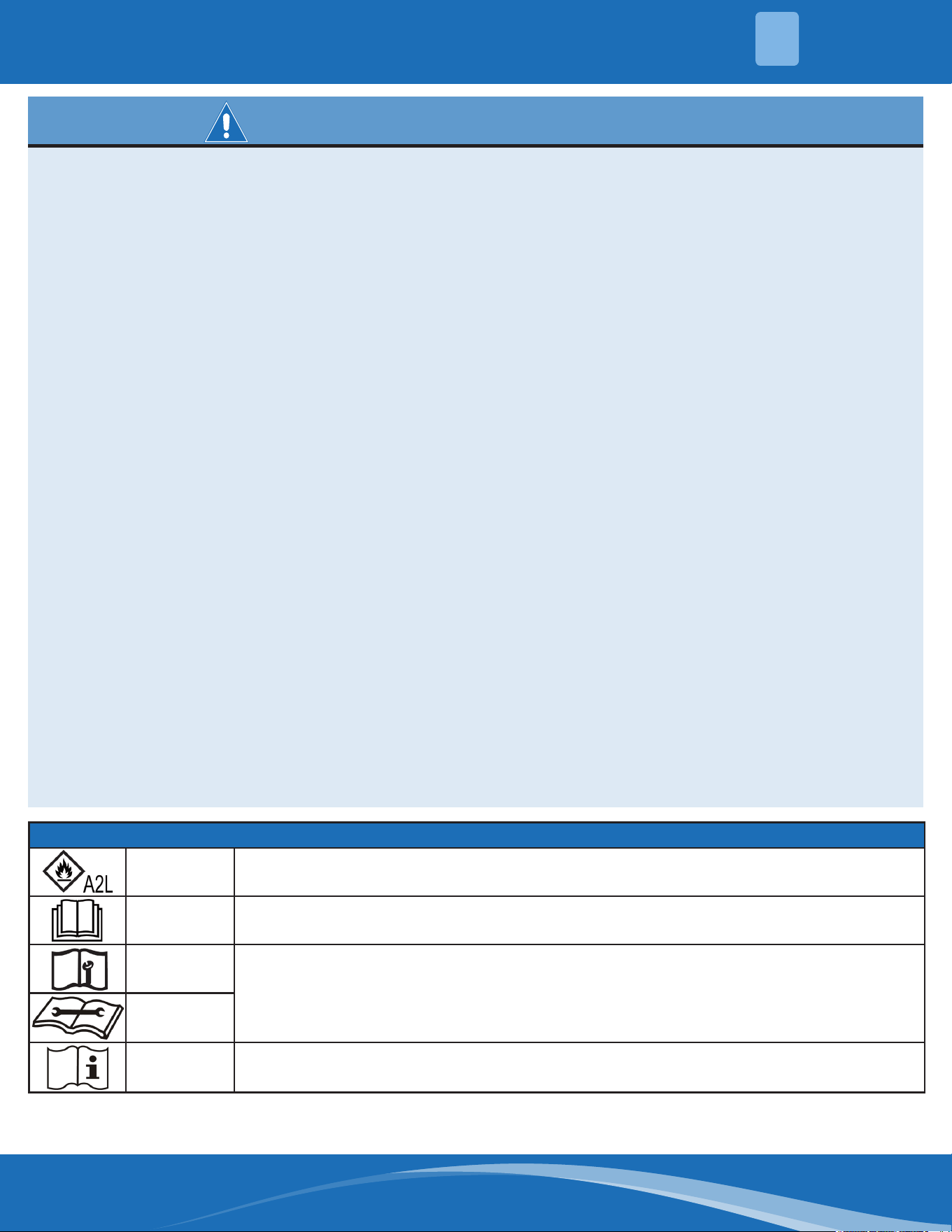
Symbols Displayed on Indoor & Outdoor Unit
WARNING
This symbol shows that this appliance uses a ammable refrigerant. If the refrigerant
is leaked and exposed to an external ignition source, there is a risk of re.
CAUTION This symbol shows that the operation manual should be read carefully.
CAUTION
This symbol shows that a service personnel should be handling this equipment with
reference to the installation manual.
CAUTION
CAUTION
This symbol shows that information is available such as the operating manual or
installation manual.
SAFETY
1
mrcool.com9
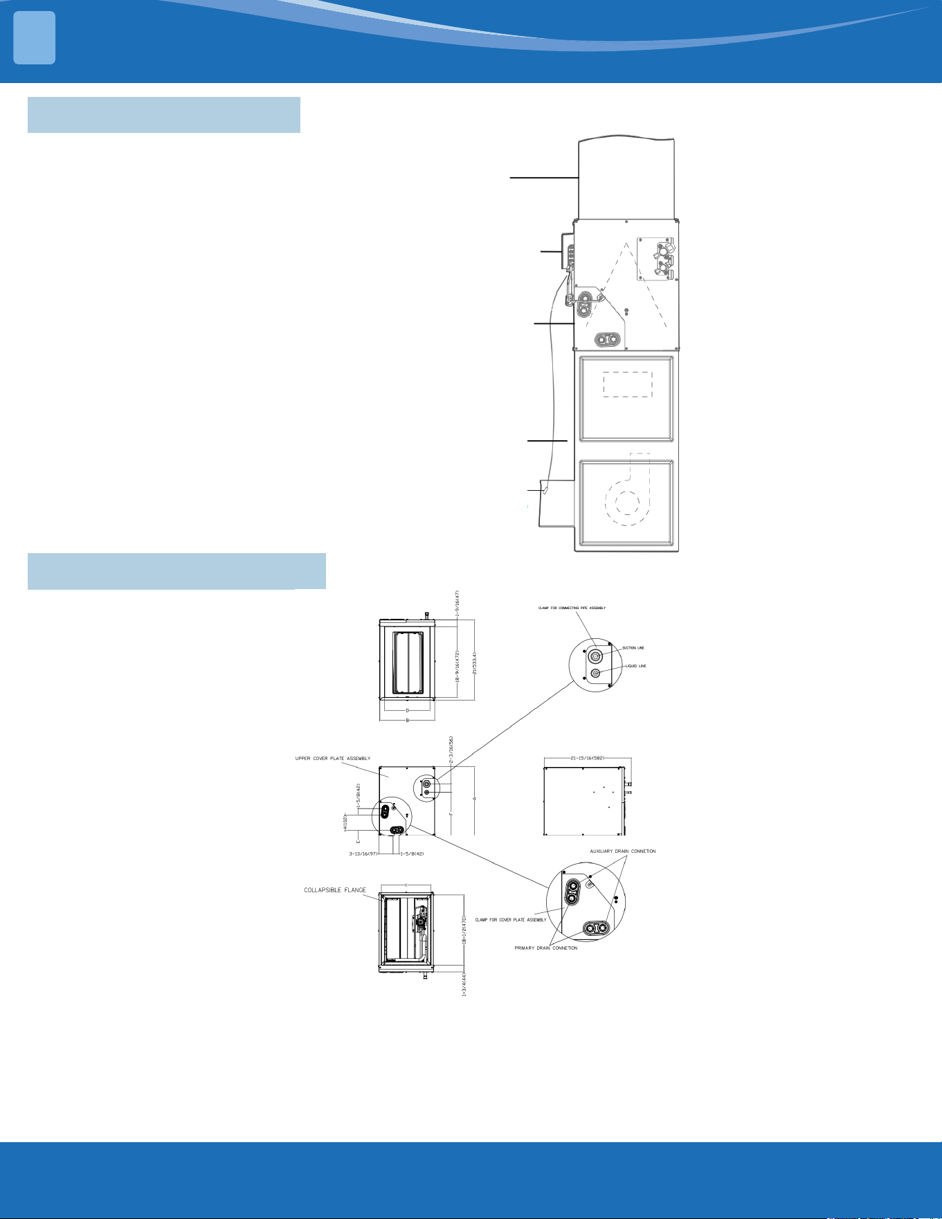
2.1 System Introduction
SYSTEM OVERVIEW
2
Duct
A-Coil Mini
Interface
Coil
Furnace
Room temperature Sensor (T1)
(Installed in the gas furnace return
air outlet)
2.2 Dimensional Drawings
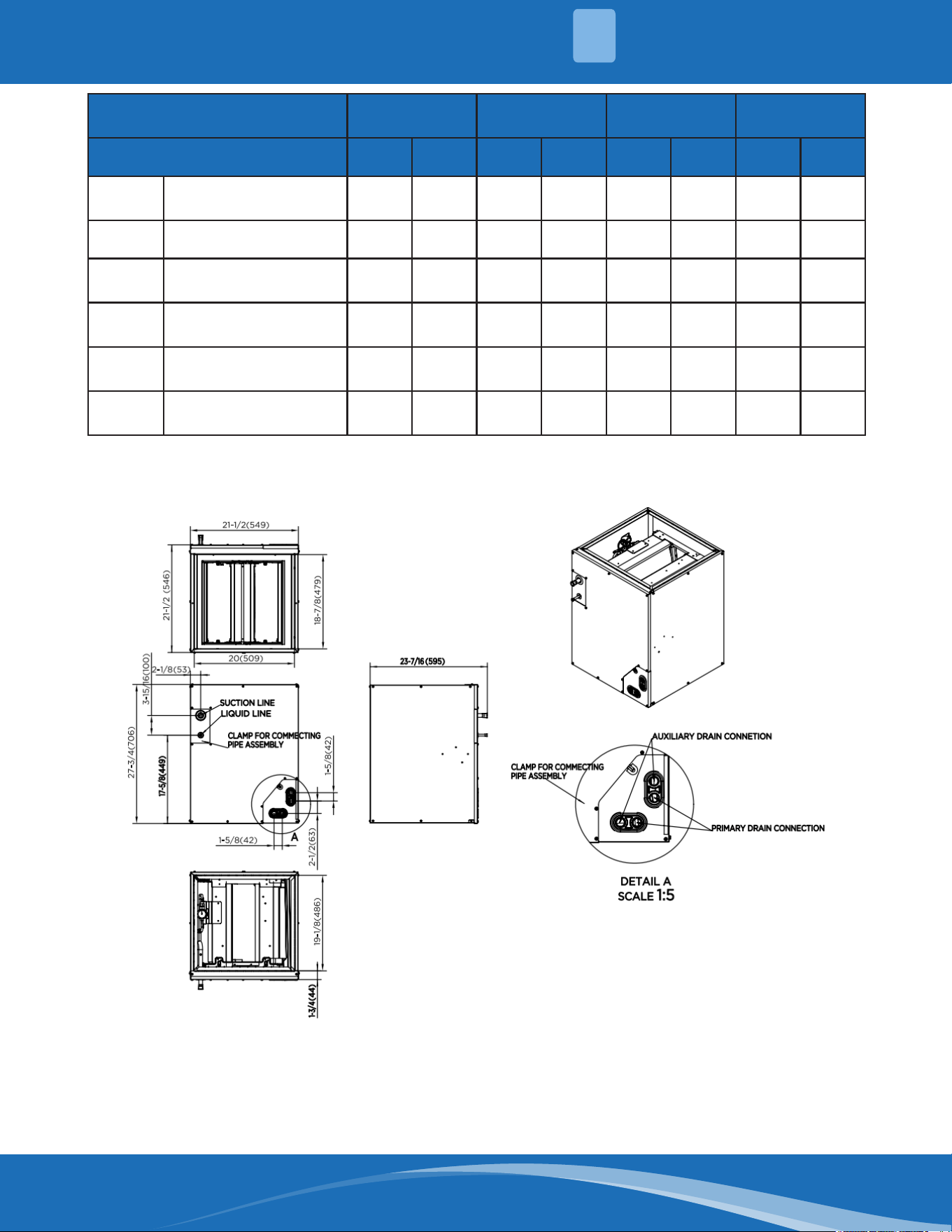
mrcool.com 10
10
2
SYSTEM OVERVIEW
Model
MCMP-
1824AOTB
MCMP-
1824BTOPB
MCMP-
3036BOTB
MCMP-
4860DOTB
Dimensions inch mm inch mm inch mm inch mm
A Model Height 18 457 18 457
23-
9/16
599 28 711
B Model Width 14-1/2 368 17-1/2 445 17-1/2 445 24-1/2 622
C
Supply Air Opening
Width
13-1/4 336
16-
3/16
411
16-
3/16
411 23-1/4 591
D
Return Air Opening
Width
11-
15/16
303
14-
15/16
380
14-
15/16
380 23-1/8 587
E
Condensate Drain
Height
1-7/16 38 1-7/16 38 1-7/16 38 2-3/16 55
F Liquid Line Height 11-3/8 290 11-3/8 290 16-3/8 417
21-
7/16
545
MCMP4860COTB
mrcool.com11
SYSTEM OVERVIEW
2
2.3 Clearances
Following clearances should be provided during installation.
A. Maintenance and service access, including coil cleaning and coil assembly removal.
B. Refrigerant piping and connections.
C. Condensate drain line.
Ensure proper installation, place on a solid and level site.
Ensure there is enough space required for installation and maintenance.
mrcool.com 12
12
2
SYSTEM OVERVIEW
2.4 Fan Performance
2.5 Refrigerant Diagram
mrcool.com13
SYSTEM OVERVIEW
2
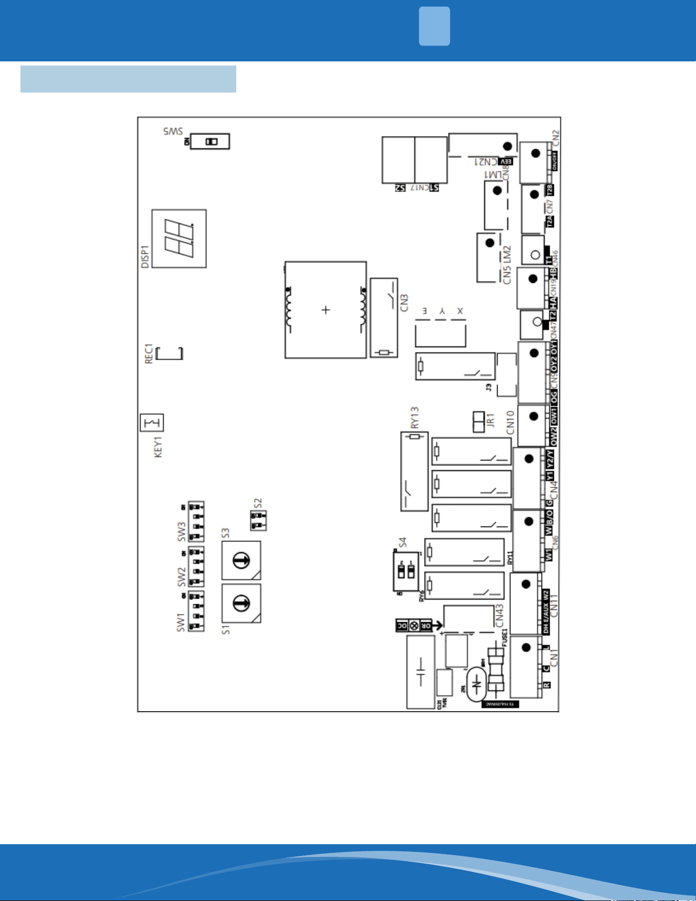
2.6 Wiring Diagram
mrcool.com 14
14
2
SYSTEM OVERVIEW
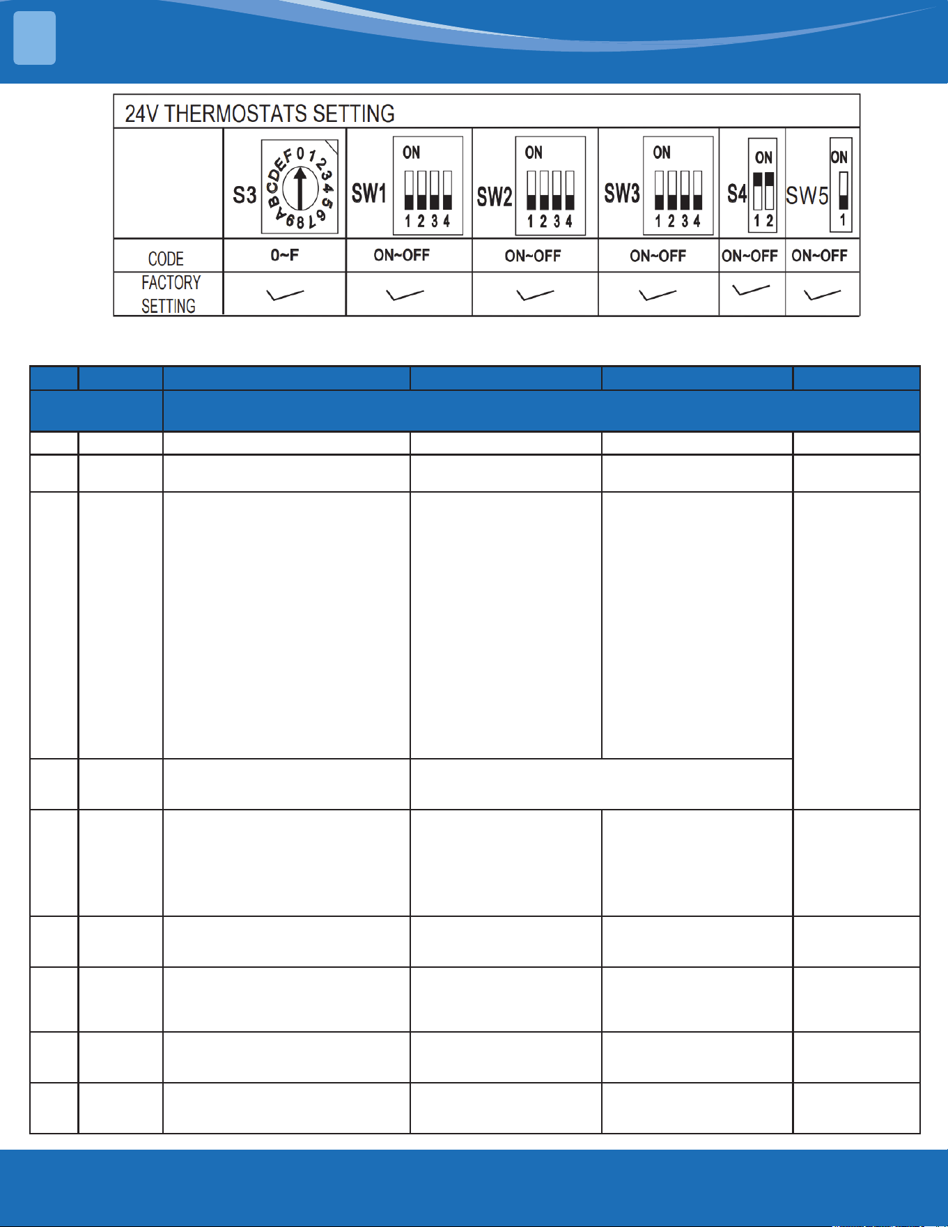
2.7DIPSwitchDenitions
mrcool.com15
SYSTEM OVERVIEW
2
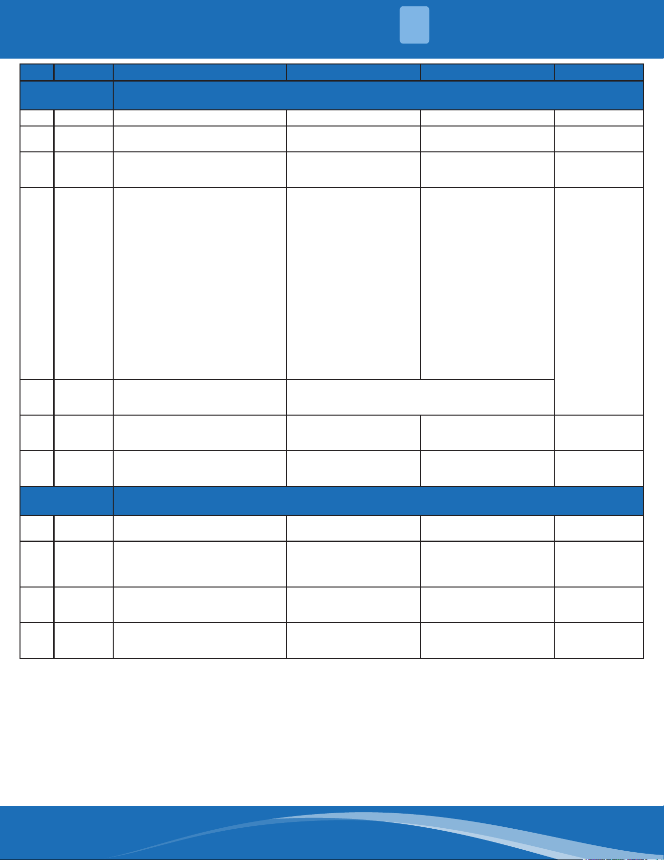
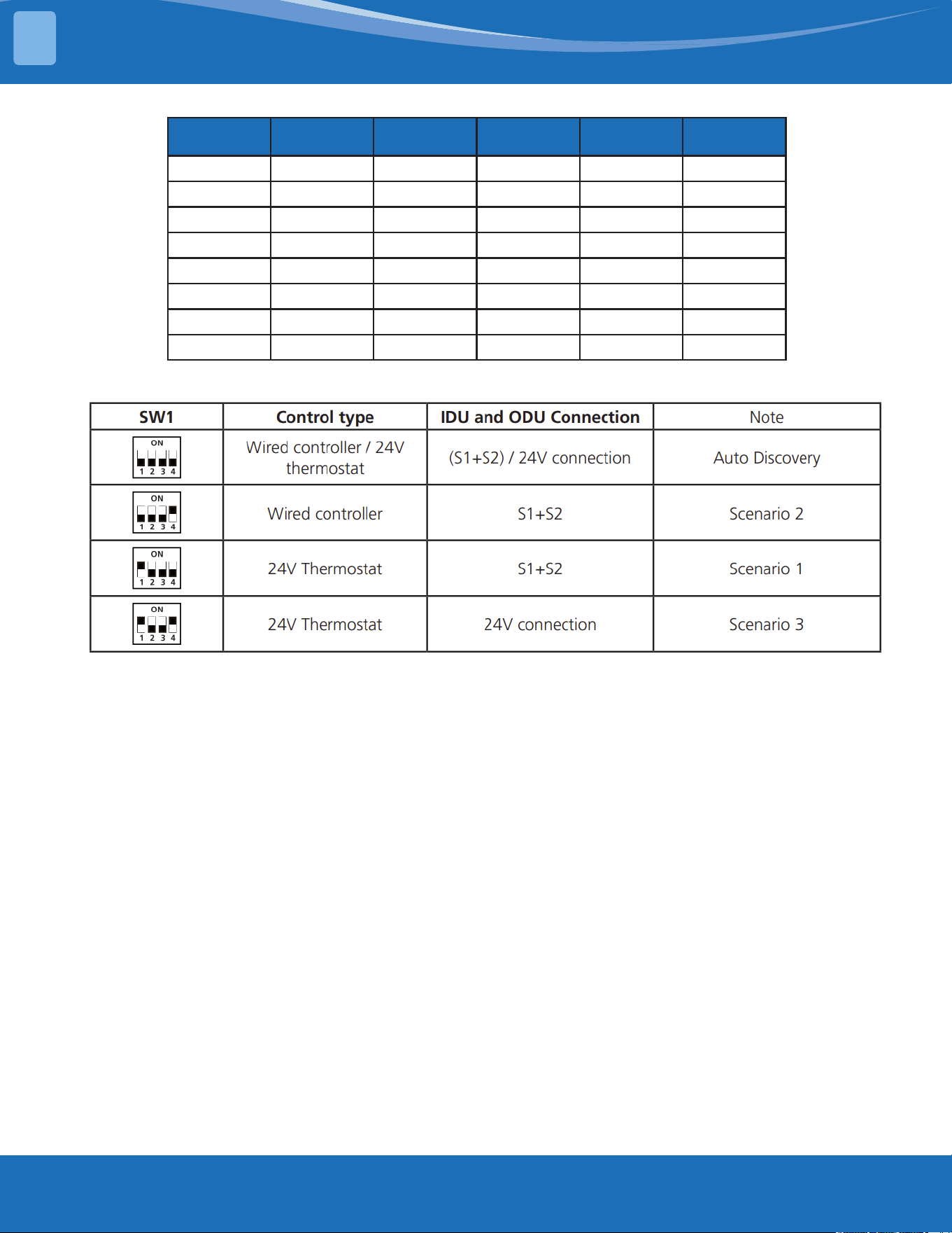
A. Function DIP Switch Settings
The 24V thermostat mode needs to refer to the following settings
No. Dial Code Function ON OFF ( Default) Note
Control
Scenario
Scenario 1: 24V Tstat, S1+S2
1 SW1-2 Anti-cold blow protection option No (Default) Yes
2 SW1-3
Single cooling/heating and cooling
options
Cooling (Default) Cooling & Heating
3 SW2-4 Compressor
The operation of the heat
pump is limited by the
outdoor temperature, and
the operation of auxiliary
heat is not limited. The
system makes judgments
according to the following
rules:1) The compressor
can be operated when
the outdoor temperature
is ≥S3 DIP switch
temperature +2°C.
2) The compressor cannot
be operated when the
outdoor temperature is
lower than S3 DIP switch
temperature.
[Default] The operation
of the heat pump is
limited by the outdoor
temperature, and the
operation of auxiliary heat
is not limited. The system
makes judgments based
on the following rules: 1)
The compreessor cannot
be operated when the
outdoor temperature is
lower than the S3 DIP
switch.
2) The compressor can
be operated when the
outdoor temperature
is ≥S3 DIP switch
temperature +2°C.
SW2-4 and S3
need to be
working together
4
Rotary
Switch S3
Set outdoor temperature
Limitation (for auxiliary heating or
compressor)
Table A
5 SW3-1
Maximum continuous runtime
allowed before the system
automatically stages up capacity
to satisfy set point. This adds 1 to
5 °F to the user set point in the
calculated control point to increase
capacity and satisfy user set point.
30 minutes [Default] 90 minutes
6 SW3-2
Cooling and heating Y/
Y2 temperature dierential
adjustment.
Compressor slower speed
[Default] Faster
Compressor
Only aects
compressor
7 S4-1 Default ON
[Default] For single stage
supplemental heat, W1 and
W2 are connected.
For dual stage
supplemental heat, W1
and W2 are controlled
independently.
8 S4-2 DH function selection
[Default} Dehumidication
control not available.
Dehumidication feature
is enabled through the
thermostat.
9 SW5
Selection of the second Refrigerant
Sensor
Both Refrigerant Sensor
are used
Only use the rst
Refrigerant Sensor,
interface is CN8
mrcool.com 16
16
2
SYSTEM OVERVIEW
No. Dial Code Function ON OFF ( Default) Note
Control
Scenario
Scenario 2: Wired Controller: S1+S2
1 SW1-2 Anti-cold blow protection option No (Default) Yes
2 SW1-3
Single cooling/heating and cooling
options
Cooling (Default) Cooling & Heating
3 SW2-1
Temperature dierential to active
rst stage furnace heating for
HP+furnace mode
1°C [Default] 2°C
4 SW2-4
Compressor/Auxiliary heat outdoor
ambient lockout
The operation of the heat
pump is limited by the
outdoor temperature, and
the operation of auxiliary
heat is not limited. The
system makes judgments
according to the following
rules:1) The compressor
can be operated when
the outdoor temperature
is ≥S3 DIP switch
temperature +2°C.
2) The compressor cannot
be operated when the
outdoor temperature is
lower than S3 DIP switch
temperature.
[Default] Only one heat
pump or auxiliary heat
can be operated. The
system makes judgments
according to the following
rules: 1) When the
outdoor temperature is
lower than the S3 DIP
switch temperature,
the compressor is not
allowed to be operated,
but the auxiliary heat
is allowed to operate;
2) When the outdoor
temperature is ≥S3 DIP
switch temperature +2°C,
the compressor can be
operated, but the auxiliary
heat cannot be operated.
SW2-4 and S3
need to be
working together
5
Rotary
Switch S3
Set outdoor temperature
Limitation (for auxiliary heating or
compressor)
Table A
6 SW3-3
Temperature dierential to active
second stage furnace heating for
furnace only or HP+furnace
3°C [Default] 2°C
7 SW5
Selection of the second Refrigerant
Sensor
Both Refrigerant Sensor
are used
Only use the rst
Refrigerant Sensor,
interface is CN8
Control
Scenario
Scenario 2: Wired Controller: S1+S2
1 SW1-3
Single cooling/heating and cooling
options
Cooling [Default] Cooling & Heating
2 S4-1 Default ON
[Default] For single stage
supplemental heat, W1 and
W2 are connected.
For dual stage
supplemental heat, W1
and W2 are controlled
independently.
3 S4-2 DH function selection
[Default] Dehumidication
control not available
Dehumidication feature
is enabled through the
thermostat
4 SW5
Selection of the second Refrigerant
Sensor
Both Refrigerant Sensor
are used
Only use the rst
Refrigerant Sensor,
interface is CN8
mrcool.com17
SYSTEM OVERVIEW
2
S3 S3 (°F) S3 (°C) S3 S3 (°F) S3 (°C)
0 OFF OFF 8 10 -12
1 -22 -30 9 18 -8
2 -18 -28 A 25 -4
3 -15 -26 B 32 0
4 -11 -24 C 36 2
5 -8 -22 D 39 4
6 -4 -20 E 43 6
7 3 -16 F 46 8
Table A
Function Combination Table of SW1-1 and SW1-4
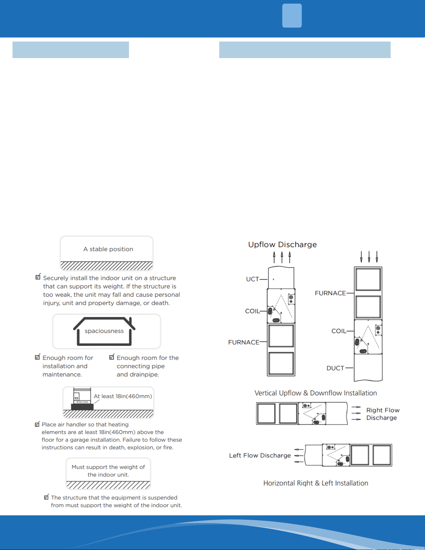
mrcool.com 18
18
3.1 Location Selection
DO NOT install the unit in the following Locations:
• DO NOT install the indoor unit in a moist
environment. Excessive moisture can corrode
the equipment, electrical components, and cause
electrical shorts.
• Areas with strong electromagnetic waves.
• Coastal areas with high salt content in the air.
• Areas with oil drilling or fracking.
• Areas that store ammable materials or gas.
• Areas where there may be detergent or other
corrosive gases in the air, such as bathrooms, or
laundry rooms.
• Areas where the air inlet and outlet may be
obstructed.
• Danger of explosion. Keep ammable materials
and vapors, such as gasoline, away from the air
handler.
WARNING: MUST BE INSTALLED IN A LOCATION
THAT MEETS THE FOLLOWING REQUIREMENTS:
3.2 Indoor Unit Installation (A-COIL)
Installation and Trap Connection:
1. See the following gure for the coil installation
and drain connection.
2. Installation steps for cased coil:
A. Shut o or disconnect gas furnace's power and
remove gas pipe if necessary.
B. Disconnect and remove a sucient portion of
the supply ductwork to provide clearance for the
cased coil.
C. Ensure that the coil is leveled well and seal the gap
between the coil and furnace. See Fig. 3-1. In case
that the coil and furnace sizes are not matched,
use the proper size of sheet metal or other
material to ll the gap and seal the gap to prevent
air leaks.
D. Reconnect the ductwork to the coil case, and seal
any leakage.
E. Reconnect the power line on the gas furnace, turn
on the furnace to check any sign of leakage.
Typical Coil Installation on Furnace:
Downow Discharge
INSTALLATION
3
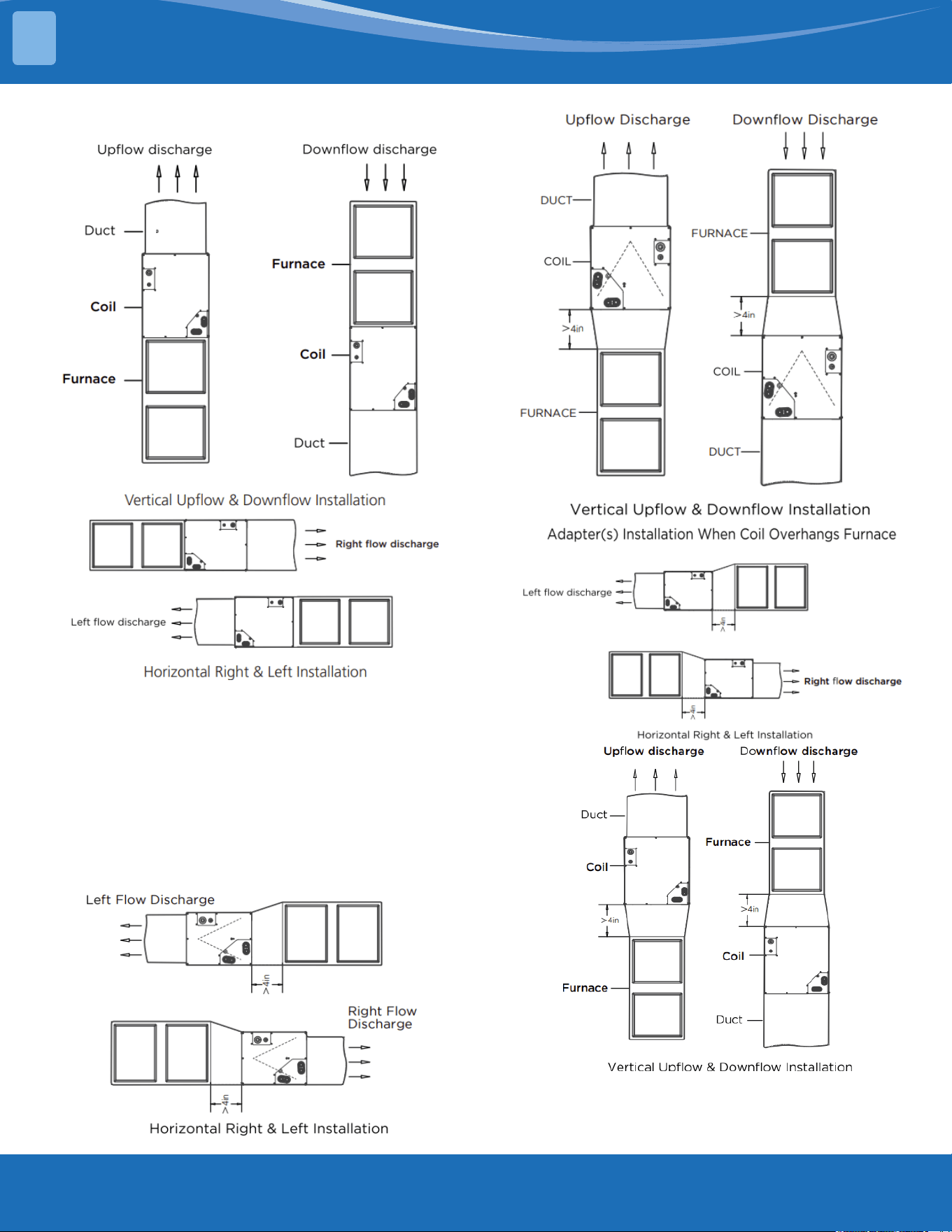
mrcool.com19
Model MVBM-60C28T6N10 coil installation on
furnace
UpowCoilInstallation:
The cased coil is designed to r furnaces of the same
width.
1. Set the coil in place on a upow furnaces
discharge air opening.
2. Ensure the coil is level for proper condensate
drainage. Do not tip the coil toward the
condensate drain. The coil casing does not need to
be fastened or screwed to the furnace.
3. When installing a wider coil and a narrow furnace,
create a eld fabricated adapter.
Adapter(s) installation when Model MVBM-
60C28T6N10 coil overhangs furnace
INSTALLATION
3
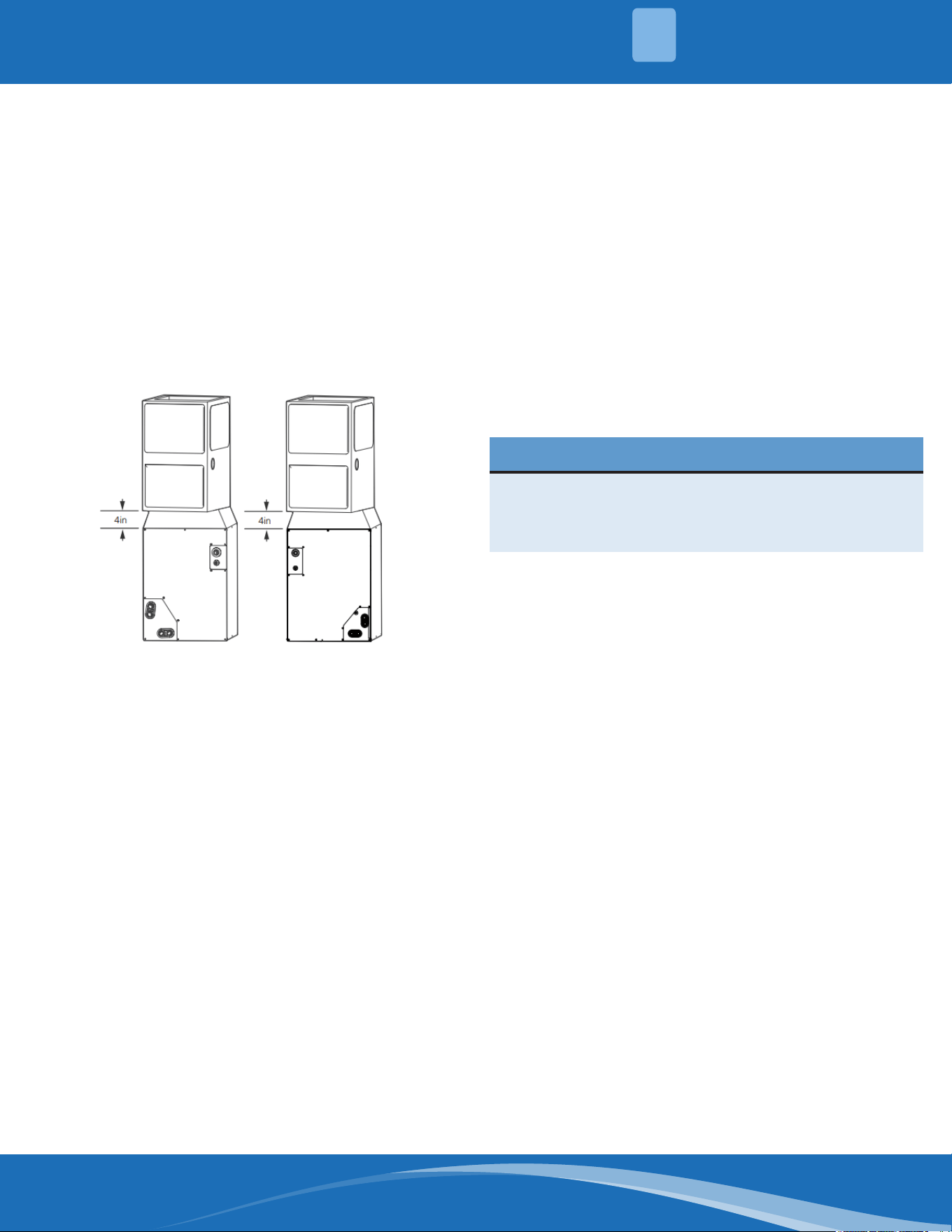
mrcool.com 20
20
NOTE: On upow installations where the indoor coil
is placed in an unconditioned space, a 6" wide piece
of insulation should be applied and wrapped around
the outside of the coil casing and supply duct contact
point.
NOTE: Consult the furnace installation instructions for
any special requirements when installing the coil to
the furnace.
DownowCoilInstallation:
IMPORTANT: if the airow is high due to ductwork or
other causes, and there is a chance for water blow
o, it is recommended that a 4-in. minimum eld-
supplied adapter be placed between the coil and the
furnace to allow the air to distribute evenly to both
coil slabs.
1. Set the cased coil on the supply duct opening.
2. Place a eld fabricated 4-in. minimum adapter on
the coil casing. The adapter should be tapered to
r the coil/furnace combination when one of them
is larger than the other.
3. Set the furnace on the adapter.
NOTE: In a downow installation with a 4-way
multiplies furnace, break o the perforated duct
anges on the furnace. See furnace installation
instructions.
Horizontal Coil Installation:
The unit can be installed on a work platform, secured
to roof trusses in the attic, suspended from hangers
on oor joist in a crawl space, or installed on blocks. It
is designed to allow airow in either direction, to mate
with a horizontal-left or horizontal-right furnace.
Ensure the coil cabinet is level side to side and front
to back. It is allowable to add up to 1/2-in additional
slope over length and depth of the coil cabinet in the
direction of the drain pan.
Horizontal Right Installation:
1. Use a eld fabricated attachment plate to secure
the coil to the furnace.
2. Use self-tapping screws to mount the attachment
plates to the coil casing.
3. Connect the furnace snugly against the coil casing.
4. Seal the joint between the coil casing and the
furnace to create and air tight seal using locally
approved materials.
5. If the coil is wider than the furnace, use a 4-in
minimum transition and self-tapping screws to
attach the furnace.
Horizontal Left Installation:
1. Unbend the 4 tabs at the right side of the casing.
2. Connect the furnace snugly against the coil casing.
3. Use the self-tapping screws to attach the furnace.
4. Seal the joints between the coil casing and the
furnace to create an air tight seal using locally
approved materials.
5. If the coil is wider than the furnace, use a 4-in
minimum transition and self-tapping screws to
attach the furnace.
Condensate Drain Line Connection
CAUTION
Failure to follow this caution may result in property
damage. When installing over a nished ceiling and/
or living area, install a eld-fabricated secondary
condensate pan under the entire unit.
The coil is designed to dispose of accumulated
water through built-in condensate drain ttings. It
is recommended that PVC ttings be used on the
condensate pan. Do not over-tighten, nger tighten
plus 1-1/2 turns. Be sure to install plastic plugs in
the unused condensate drain ttings. Two 3/4in
female threaded pipe connections are provided in
each coil condensate pan. A trap is not necessary on
the condensate line if on the supply air side of the
furnace. Consult local codes for additional restrictions
or precautions. If the local codes require a trap, then
the following guidelines are suggested to assure
proper drainage. Install a trap in the condensate line
of the coil as close to the coil as possible. Make the
trap at least 3in (76mm) deep and no higher than the
bottom of the units condensate drain opening. Pitch
the condensate line 1in (25.4mm) for every 10ft. of
length to an open drain, sump, exterior drainage.
Make sure that the outlet of each trap is below
its connection to the condensate pan to prevent
condensate from overowing the drain pan. Prime all
traps, test for leaks, and insulate the traps and lines if
located above a living area.
INSTALLATION
3
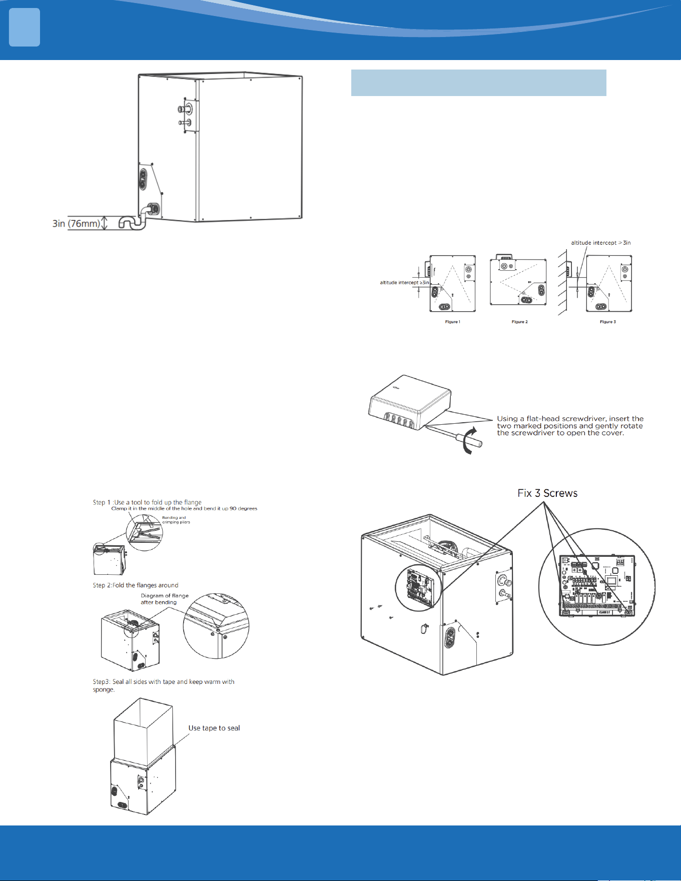
mrcool.com21
NOTE: If the unit is located in or above a living space
where damage may result from condensate overow,
a eld-supplied, external condensate pan should be
installed underneath the entire unit, and a secondary
condensate line (with an appropriate trap) should
be ran from the unit into the pan. Any condensate
in this external condensate pan should be drained
to a noticeable place. As an alternative to using an
external condensate pan, some localities may allow
the running of a separate 3/4in (19mm) condensate
line (with an appropriate trap) per local code to a
place where the condensate will be noticeable. The
owner of the structure must be informed that when
condensate ows from a secondary drain or external
condensate pan, the unit requires servicing or water
damage will occur. To further protect against water
damage, install a oat switch to shut the unit o if the
water in the secondary pan gets to high.
Air Duct Installation:
3.3 Installation of MINI Interface
1. Choose your install location.
Priority should be given to installing on the front of
the coil, or you can choose to install it on the side or
on a nearby wall as needed.
2. Dismantling panels.
Figure 1: installed on the side of the coil (vertical
mounting, you can choose left or right).
Figure 2: Installed on the wall of the coil (horizontal
mounting).
Figure 3: Installed on the wall of the coil.
3. Dismantling the control box.
Using a screwdriver, pull at the two positions shown
in the diagram.
4. Fixed box.
Fix 3 screws, 2 of which require drilling.
5. Cut o the cover wiring port.
INSTALLATION
3
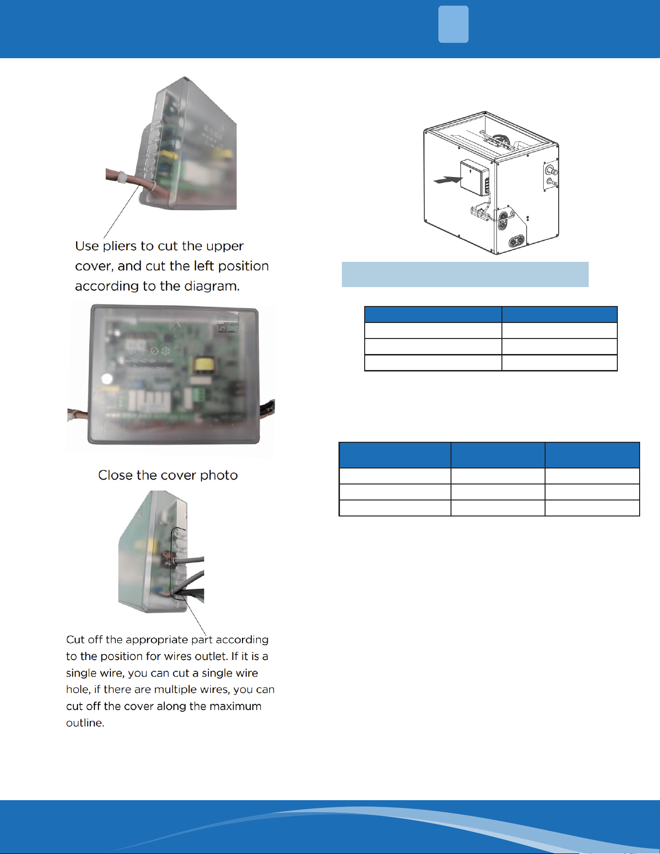
mrcool.com 22
6. Close the lid.
Close the cover to complete the installation of the
control box.
3.4 Refrigerant Pipe Installation
Recommended Copper Pipe Thickness:
Pipe Diameter (inch(mm)) Thickness(inch/mm)
Ø3/8 (Ø9.52) 0.028/0.7
Ø5/8 (Ø15.9) 0.03/0.75
Ø3/4 (Ø19) 0.031/0.8
Maximum Length and Drop Height:
Ensure that the length of the refrigerant pipe, the
number of bends, and the drop height between the
indoor and outdoor units meets the requirements
shown in the following table.
Capacity(kBtu/h)
Max. Length
(ft/m)
Max. Elevation
(ft/m)
18 98.4/30 65.6/20
24~30 164/50 82/25
36~60 246/75 98.4/30
Caution:
1. The capacity test is based on the standard length
and the maximum permissive length is based on
the system reliability.
2. Oil traps
• If oil ows back into the outdoor unit's
compressor, this might cause liquid compression
or deterioration of oil return. Oil traps in the rising
gas piping can prevent this.
• An oil trap should be installed every 20ft (6m) of
vertical suction line riser (<36000Btu/h unit).
• An oil trap should be installed every 32.8ft (10m)
of vertical suction line riser (≥36000Btu/h unit).
INSTALLATION
3
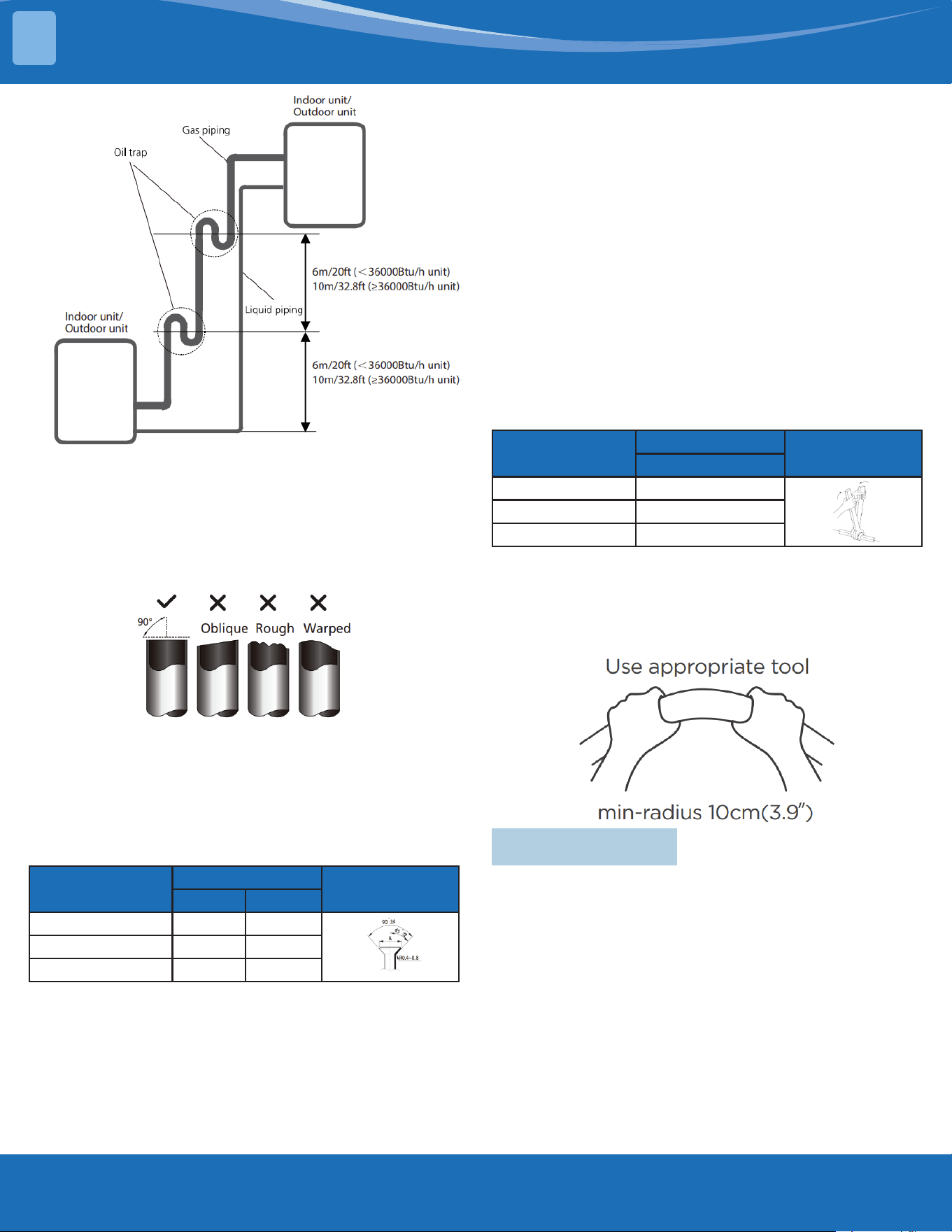
mrcool.com23
The Procedure of Connecting Pipes:
1. Choose the pipe size according to the specication
table.
2. Conrm the cross way of the pipes.
3. Measure the necessary pipe length.
4. Cut the selected pipe with a pipe cutter.
• Make the section at and smooth.
5. Insulate the copper pipe.
• Before test operation, the joint parts should not
be heat insulated.
6. Flare the pipe.
• Inset a are nut into the pipe before aring the
pipe
• According to the following table to are the pipe.
Pipe Diameter
(inch(mm))
Flare Dimension A
Flare Shape
Min. Max.
Ø3/8 (Ø9.52) 0.52/13.2 0.53/13.5
Ø5/8 (Ø15.9) 0.76/19.2 0.78/19.7
Ø3/4 (Ø19) 0.91/23.2 0.93/23.7
• After aring the pipe, the opening part must
be sealed by the end cover or adhesive tape to
avoid duct or exogenous impurity's will ender
the pipe.
7. Drill holes if the pipes need to pass the wall.
8. According to the eld condition to bend the pipes
so that it can pass the wall smoothly.
9. Bind and wrap the wire together with the
insulated pipe if necessary.
10. Set the wall conduit.
11. Set the supporter for the pipe.
12. Locate the pipe and x it by the supporter.
• For horizontal refrigerant pipe, the distance
between supporters should not exceed 3.28ft
(1m.
• For vertical refrigerant pipe, the distance
between supporters should not exceed 4.9ft
(1.5m).
13. Connect the pie to the indoor and outdoor unit by
using two crescent wrenches.
• Be sure to use two crescent wrenches and
proper torque to fasten the nut, too much
torque will damage the bellmouthing, and too
little may cause a leak. Refer to the following
table for dierent pipe connections.
Pipe Diameter
(inch(mm))
Torque
Sketch Map
N.m (lb.ft)
Ø3/8 (Ø9.52) 32~39 (23.6~28.8)
Ø5/8 (Ø15.9) 57~71 (42~52.4)
Ø3/4 (Ø19) 67~101 (49.4~74.5)
NOTE: MINIMUM BEND RADIUS
Carefully bend the tubing in the middle according to
the diagram below.
DO NOT bend the tubing more than 90° or more than
3 times.
3.5 Insulation
Insulation of Refrigerant Pipe:
Cut the pipe—insulation (except joint section)—are
the pipe—piping layout and connection—vacuum—
insulate the joining parts
Purpose of Refrigerant Pipe Insulation:
• During operation the temperature of the gas pipe
and liquid pipe will be hot/cold. Therefore, it is
necessary to install insulation; otherwise it will
lower performance or burn up the compressor.
• The gas pipe temperature is low during cooling.
If there is insucient insulation it will condensate
and drip.
• The temperature of the gas pipe is high
(122°F~212°F(50°C~100°C) during heating.
Insulation must be installed to prevent burns.
INSTALLATION
3
mrcool.com 24
24
Insulation Material Selection for Refrigerant Pipe:
• The insulation rating should be over 248°F (120°C).
• Choose insulation according to local codes and
ordnances.
• The thickness of the insulation should be above
0.39in(10mm). If in a hot or wet environment use
thicker insulation.
Humidity<80%RH Humidity≥80%RH
10mm/0.39in 15mm/0.59in
Installation Highlights:
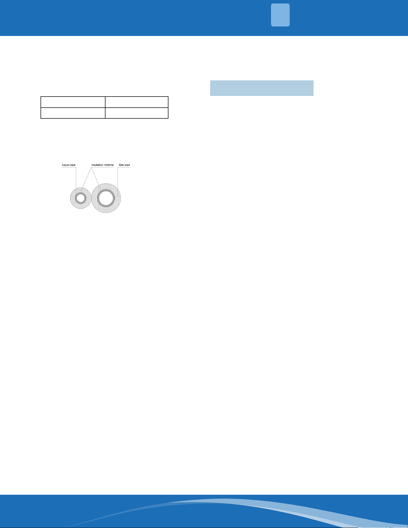
• The gas and liquid pipe should be insulated
separately, if the gas pipe and liquid pipe
were insulated together it will decrease the
performance of the system.
• The insulation material at the joint pipe should be
1.97in~3.97in(5cm~10cm) longer than the gap of
insulation material.
• The insulation material at the joint pipe should be
inserted into the gap of the insulation material.
• The insulation material at the joint pipe should be
banded to the gap pipe and liquid pipe tightly.
• The a joining part should be glued together.
• Be sure not to bind the insulating material over-
tight, it may extrude out the air in the material and
cause it to rot.
Insulation of Drainage Pipe:
Operational procedure of refrigerant pipe
insulation.
Select the suitable pipe—insulation (except joint
section)—Piping layout and connection—drainage
test—insulate the joint parts.
Purpose of drainage pipe insulation.
The temperature of the condensate drainage water
is very low. If the insulation is not enough, it shall for
dew and may leak which will cause damage to the
house.
Insulation material selection for drainage pipe.
• The insulation material should be ame retardant
material, the ame retardancy of the material
should be selected according to the local law.
• Thickness of the insulation layer is usually above
10mm/0.39in.
• Use specic glue to past the seam of insulation
material, and then bind with adhesive tape. The
width of tape shall not be less than 5cm/1.97in.
Make sure it is rm and avoid dew.
Installation and highlights of insulation
construction.
• The single pipe should be insulated before
connecting to another pipe, the joint part should
be insulated after the drainage test.
• There should be no insulation gap between the
insulation material.
3.6 Electrical Wiring
Highlights of Electrical Wiring Installation:
• All wiring must comply with local and national
electrical codes, regulations, and must be installed
by a licensed electrician.
• All electrical connections must be made according
to the Electrical Connection Diagram located on
the panels of the indoor and outdoor unit.
• If there is a serious safety issue with the power
supply, stop work immediately. Explain your
reasoning to the client, and refuse to install the
unit until the safety issue is properly resolved.
• Power voltage should be within 90~110% of the
rated voltage. Insucient power supply can cause
malfunction, electrical shock, or re.
• Installation of an external surge suppressor at the
outdoor disconnect is recommended.
• If connecting power to xed wiring, a switch or
circuit breaker that disconnects all poles and has
a contact separation of at least 1/8in(3mm) must
be incorporated in the xed wiring. The qualied
technician must use an approved circuit breaker
or switch.
• Only connect the unit to an individual branch
circuit. Do not connect another appliance to that
outlet.
• Make sure to properly ground the air conditioner.
• Every wire must be rmly connected. Loose wiring
can cause the terminal to overheat, resulting in
product malfunction and possible re.
• Do not let wires touch or rest against refrigerant
tubing, the compressor, or any moving parts
within the unit.
• If the unit has an auxiliary electric heater, it must
be installed at least 40in(1m) away from any
combustible material.
• To avoid electrical shock, never touch the electrical
components after the power supply has been
turned o. After turning o the power, always wait
10 minutes or more before you touch the electrical
components.
• Make sure that you do not cross your electrical
wiring with your signal wiring as this may cause
distortion, interference, or possibly damage to the
circuit boards.
• No other equipment should be connected to the
same power circuit.
• Connect the outdoor wires before connecting the
indoor wires.
INSTALLATION
3
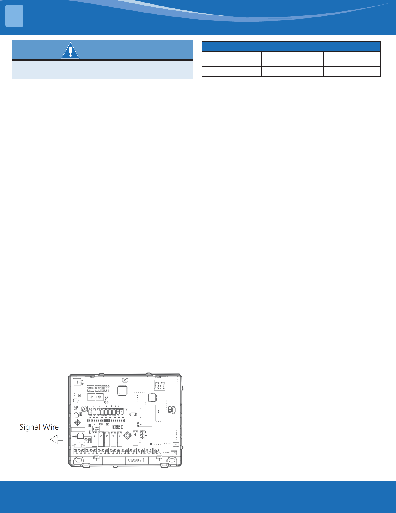
mrcool.com25
WARNING
Before performing any electrical or wiring work, turn
o the main power to the system.
Indoor Wiring:
The power to the unit must be disconnected before
any wiring. Be sure to show application of a ferrite
clamp and room temp sensor and cable. Make a note
to review the dierent application (scenarios) options
for proper wiring. Make sure a strain relief and
proper conduit are used when connecting to the box,
recommended use of metal-clad cable.
NOTE: Use copper wire only. Separate the power
supply leads and communication leads by the strain
relief or segregate the power supply leads from the
communication leads.
Instruction for installation of the critical-to-safety
wiring connection of the leak detection sensor or
leak detection system to the furnace assembly. The
wiring shall not be less than 18 AWG with a minimum
insulation thickness of 1.58mm (1.58mm) or protected
from damage. Critical-to safety wiring is any eld
installed wiring necessary to fulll the requirements of
the minimum room area in the event of a detection of
a leak.
The appliance shall not be installed on furnaces with
an inductive electrical greater than Le as calculated as
follows:
The switched electrical load (Le) in kVA is less than or
equal to:
-Le=5*(6,7/Su)4 when breaking all phases;
-Le=2,5*(6,7/Su)4 when breaking two legs of a three-
phase load, or when breaking one or two legs of a
single phase load.
Where Le is the switched inductive electrical load in
kilo volt-amperes (kVA);
Su is the burning velocity of a refrigerant in
centimeters per second (cm/s).
Detection of a leak shall turn on the indoor fan at the
highest available speed or turn it on to no less than
the minimum airow (Qhmin).
Line Gauge
Outdoor-Indoor
Signal Wire
Line Diameter (AWG) 20
24V Signal Wire Line Diameter (AWG) 18
INSTALLATION
3
mrcool.com 26
26
Ratings:
Electrical-Inputs:
Input Type Input Rating Terminals
Recommended Wire
Range/Torque
Power Input
24VAC, 60Hz, 300mA,
Class 2
Terminal Block CN1-3(R),
CN1-2(C)
14-22 AWG/0.5N·m
Remove Control Signal
Input
12VDC, SELV CN2 14-22 AWG/0.5N·m
Communication:
Type Rating Terminal
Recommended Wire
Range/Torque
Communication Between
Indoor and Outdoor Unit
5VDC, Class 2, Limited
Energy (≤15W)
CN17
14-22 AWG/0.5N·m
Communication Between
Data Conversion Board
and External Thermostat
24VAC, 60Hz, Class 2 CN4, CN6, CN11
Communication Between
Data Conversion Module
PWB and Centralized
Controller
5VDC, Class 2 CN3
External Communication
18VDC, Class 2, Limited
Energy (15W)
CN19
Communication Between
Data Conversion Module
PWB and Refrigerant
Sensor
5 VDC, Class 2 CN5, CN8
Outputs:
Type Rating Terminal
Recommended Wire
Range/Torque
Control Device for
Furnace (Relay, RY7, RY8)
24VAC, 60Hz, Class 2,
General Use (Signal Use)
CN9
14-22 AWG/0.5N·m
Control Device for
Furnace (Relay, RY9, RY10)
24VAC, 60Hz, Class 2,
General Use (Signal Use)
CN10
Control Device for
Outdoor Unit When Full
24V communication
(Relay, RY11)
CN43
4.1 Wiring
PRODUCT FEATURES
4
mrcool.com27
Wiring Methods:
WARNING
Please refer to the wiring nameplate for the wiring method. DO NOT connect the power cord to the
communication line as this may damage the system.
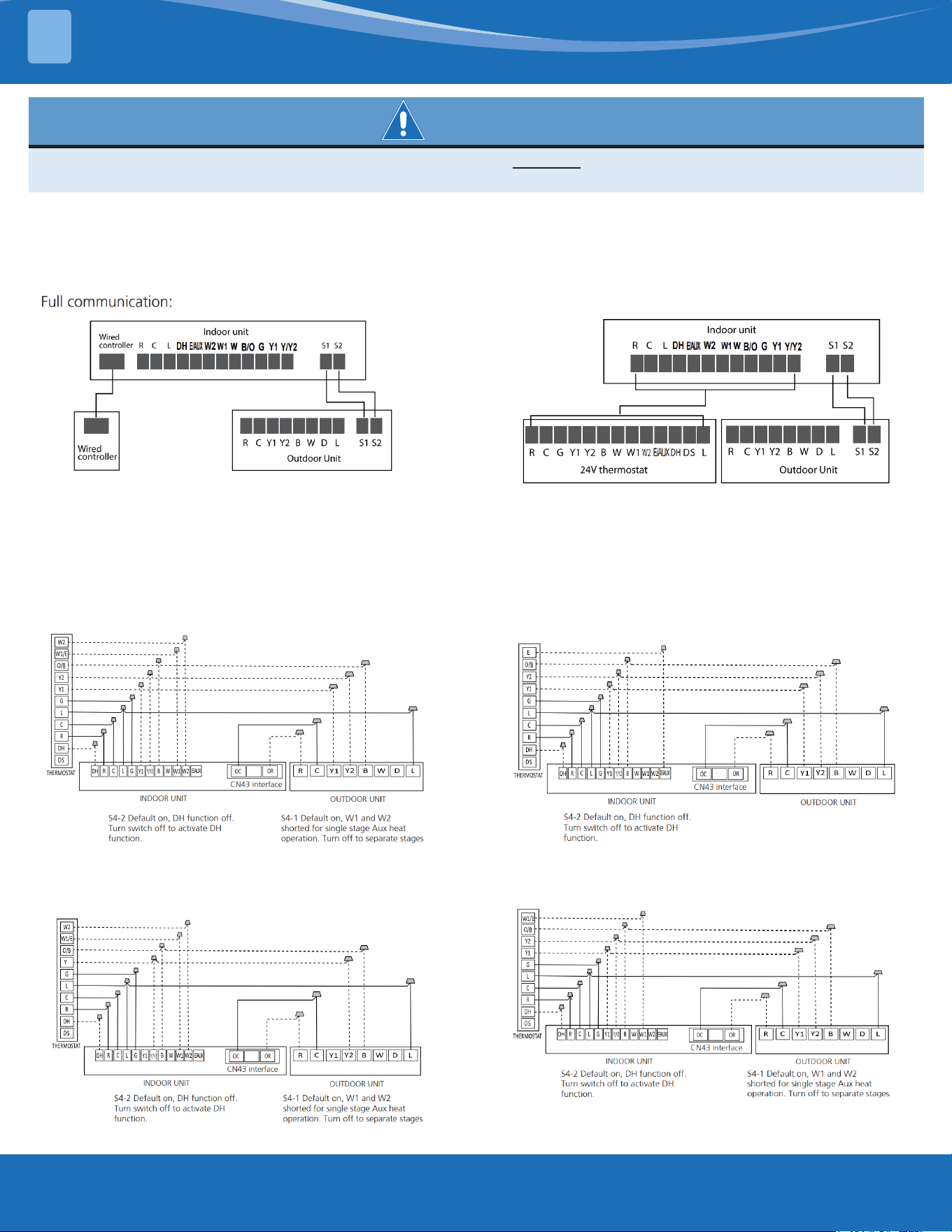
Connection method C:
The following wiring diagrams are suitable for the IDU and ODU with 24V thermostat.
Non-Communicating scheme wiring reference
NOTE: CN43 terminals OC of A-COIL Mini Interface must be connected to the outdoor unit when the full 24V communication
scheme is applied. That will stop the operation of the outdoor unit for safety if there is a refrigerant leak.
NOTE: For method A & B the equipment must have S1 & S2 communication between the indoor and outdoor
units.
Connection Method A:
Connection Method B:
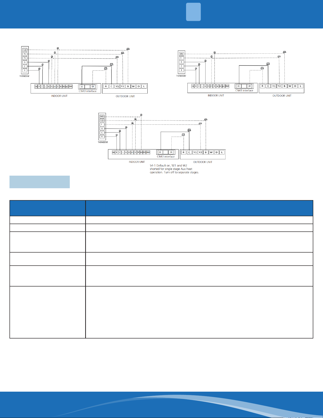
To use a 24V thermostat, you need
to refer to the following wiring:
Wiring for 4H and 2C thermostat
Wiring for 3H and 1C thermostat
Wiring for 3H and 2C thermostat
Wiring for 3H and 3C thermostat
PRODUCT FEATURES
4
mrcool.com 28
28
Wiring for 2H and 2C thermostat Wiring for 1H and 1C thermostat
Wiring for 2H and 1C thermostat
Connector Usage
R Provides 24VAC power from the furnace to the board.
C The 24VAC common wire between the furnace and the board.
OW1
First stage of furnace command line from the board to the furnace.
If the furnaces that only have a W and do not have a S2, connect OW1 to the W of the furnace and
make no connection with the OW2 signal wire.
OW2
Second stage of furnace command line from the board to the furnace. OW2 cannot be ON unless
OW1 is already ON.
OY1/OG
For 1-speed conguration, connect the OG signal to G of the furnace.
For 2-speed conguration, connect the OG signal to G of the furnace and connect the OY1 signal to
Y1 of the furnace.
OY2
For 1-speed conguration, connect this signal to Y of the furnace. In this conguration, the OY2 signal
turns on when the fan is requested while in Cool or Heat mode using the heat pump.
For 2-speed conguration, connect this signal to Y2 of the furnace. In this conguration, the OY2
signal turns on as follows:
In Fan, Cool, or Heat mode with the HP when high speed fan is requested.
In Auto Fan and Cool mode, the signal goes to high speed when the dierence between room
temperature and set point temperature is more than or equal to 1.5°C. The signal goes back to low
speed when the temperature dierence is less than 1°C.
4.2 Controls
Control signals to the furnace are the standard thermostat control signals R,C,OW1,OW2,OG,OY1, and OY2.
In addition:
Room temperature sensor to be installed in the return air.
Duct temperature sensor to be installed on the COIL as specied.
PRODUCT FEATURES
4
mrcool.com29
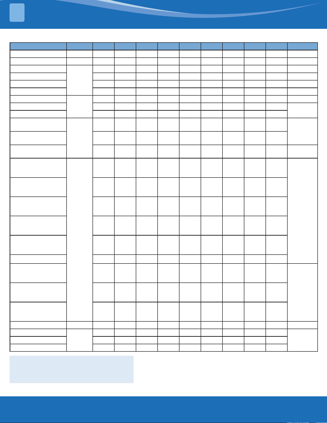
Mode Priority G Y1 Y/Y2 B W W1 W2 E/AUX DH Display
OFF / 0 0 0 0 0 0 0 0 * 00
FAN 7 1 0 0 * 0 0 0 0 * 01
Cooling Stage 1
6
* 1 0 0 0 0 0 0 1 02
Cooling Stage 2 * * 1 0 0 0 0 0 1 03
Dehumidication 1 * 1 0 0 0 0 0 0 0 04
Dehumidication 2 * * 1 0 0 0 0 0 0 05
Heat Pump Stage 1
5
* 1 0 1 0 0 0 0 1 06
Heat Pump Stage 2 * * 1 1 0 0 0 0 1
07
Heat Pump Stage 2 * * * * 1 0 0 0 1
Furnace
3
* 0 0 * 0 1 0 0 *
12
Furnace * 0 0 * 0 0 1 0 *
Furnace * 0 0 * 0 1 1 0 * 12
Furnace
4
* 1 0 1 0 1 0 0 1
12
Furnace * 1 0 1 0 0 1 0 1
Furnace * * 1 1 0 1 0 0 1
Furnace * * * * 1 1 0 0 1
Furnace * * 1 1 0 0 1 0 1
Furnace * * * * 1 0 1 0 1
Furnace * 1 0 1 0 1 1 0 1
12Furnace * * 1 1 0 1 1 0 1
Furnace * * * * 1 1 1 0 1
Furnace 1 * * * * * * * 1 * 12
Heating Zone Control
2
* 1 0 1 0 * * 0 0
13Heating Zone Control * * 1 1 0 * * 0 0
Heating Zone Control * * * * 1 * * 0 0
24V Signal Chart (Cooling & Heating)
Note:
1: 24V signal
0: No 24V signal
*: 1 or 0
The AHU will turn o if the 24V input cannot meet the table.
PRODUCT FEATURES
4
mrcool.com 30
4.3 Safety Features (NON-24V control)
SensorRedundancyandAutomaticShuto:
If one temperature sensor malfunctions, the air
conditioner continues operation and displays the
corresponding error code, allowing for emergency
use.
• When more than one temperature sensor is
malfunctioning, the air conditioner ceases
operation.
Basic Functions (NON-24V control)
Unit Element Abbreviations
Abbreviation Element
T1 Indoor room temperature sensor
T2 Evaporator coil temperature sensor
T3 Condenser coil temperature sensor
T4 Outdoor ambient temperature sensor
TP Compressor discharge temperature sensor
TS Setting Temperature
Tsc Adjusted setting temperature
Fan Mode:
When fan mode is activated
• Temperature control is disabled and no
temperature setting is displayed.
• Auto Fan: In fan-only mode, the system operates
the same as auto fan in cooling mode with the
temperature set at 75°F (24°C).
Cooling Mode:
Indoor Fan Control
1. In cooling mode, the indoor fan operates
continuously. The fan speed can be set to low,
medium, high, turbo, and auto:
2. Auto fan action in cooling mode:
• Descent Curve
• When T1-Tsc is lower than 6°F/3.5°C, the fan
speed reduces to high (OY1+OY2).
• When T1-Tsc is lower than 1°F/2°C, the fan speed
reduces to medium (OY1).
• When T1-Tsc is lower than 0.5°F/1°C, the fan
speed reduces to low (OY1).
• Rise Curve
• When T1-Tsc is higher than or equal to 1°F/2°C,
the fan speed increases to medium (OY1).
• When T1-Tsc is higher than or equal to 3°F/1.5°C,
the fan speed increases to high (OY1+OY2).
• When T1-Tsc is higher than or equal to 7°F/4°C,
the fan speed increases to turbo (OY1+OY2).
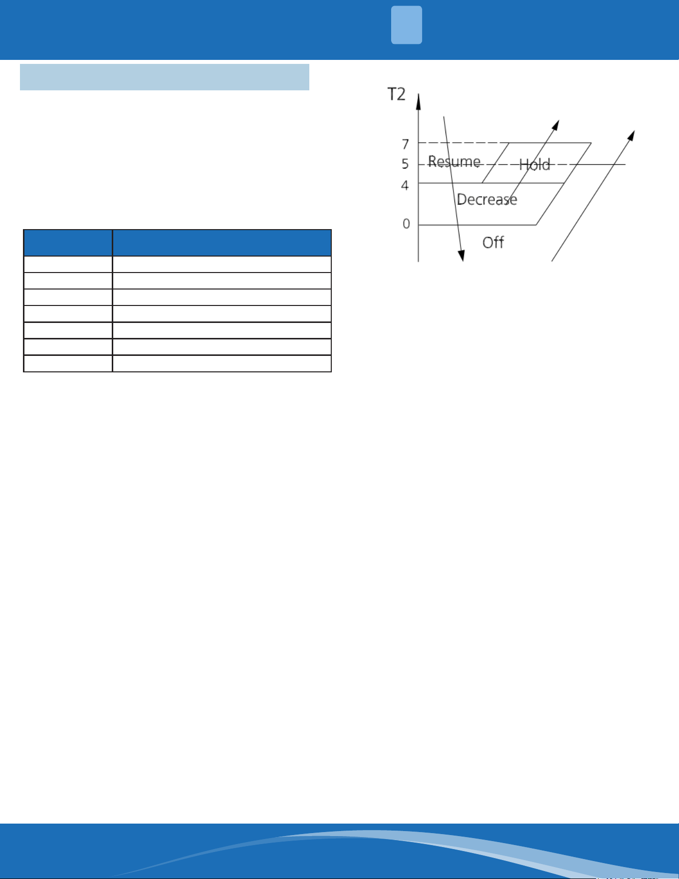
Evaporator Temperature Protection:
• O: Compressor Stops.
• Decrease: Decreases the running frequency to the
lower level per 1 minute.
• Hold: Keep the current frequency.
• Resume: No limitation for frequency.
HEATING MODE:
Indoor Fan Control
1. In heating mode, the indoor fan operates
continuously. The fan speed can be set to low,
medium, high, turbo, and auto.
• Anti-cold air function.
• Set machine: G1 G2 does not output within 1
minute of compressor stop or compressor turn
on in single heat pump mode, and output the set
fan after 1 minute of compressor opening.
• Set machine: After exiting defrost, the fan is
delayed for 30s before output.
• Single indoor machine: no anti-cold air function,
according to the set fan output. (When the
indoor unit is faulty, the set fan output will still
be sent according to the display).
2. Auto fan action in heating mode:
• Rise Curve
• When T1-Tsc is lower than -3°F/-1.5°C, the fan
speed reduces to high (OY1+OY2).
• When T1-Tsc is lower than 0°F/0°C, the fan speed
reduces to medium (OY1).
• When T1-Tsc is lower than 1°F/0..5°C, the fan
speed reduces to low (OY1).
• Descent Curve
• When T1-Tsc is higher than or equal to 0°F/0°C,
the fan speed increases to medium.
• When T1-Tsc is higher than or equal to
-3°F/-1.5°C, the fan speed increases to high
(OY1+OY2).
• When T1-Tsc is higher than or equal to -5°F/-3°C,
the fan speed increases to turbo (OY1+OY2).
PRODUCT FEATURES
4
mrcool.com31
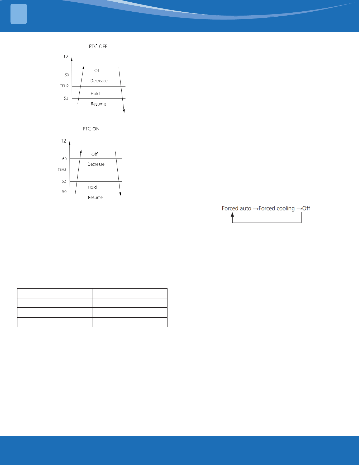
Evaporator Coil Temperature Protection:
• O: Compressor stops.
• Decrease: Decrease the running frequency to the
lower level per 20 seconds.
• Hold: Keep the current frequency.
• Resume: No limitation for frequency.
Auto-Mode:
• This mode can be selected with the remote
controller and the temperature setting can be
adjusted between 61°F~86°F (16°C~30°C).
• In auto mode, the machine selects cooling,
heating, or fan-only mode on the basis of ΔT
(ΔT=T1-Ts).
ΔT Running Mode
ΔT>3.6°F (2°C) Cooling
-5.4°F (-3°C)≤ΔT≤3.6°F (2°C) Fan-Only
ΔT< -5.4°F (-3°C) Heating*
Heating*: In auto mode, cooling only models run the
fan
• Indoor fan will run at auto fan speed.
• If the machine switches mode between heating
and cooling, the compressor will keep stopping
for a certain time and then choose the mode
according to the ΔT.
Drying Mode:
Indoor Fan Control
1. In drying mode, the indoor fan operates
continuously. The fan speed can be set to low,
medium, high, turbo, and auto.
2. Auto fan action in drying mode:
• Descent curve
• When T1-Tsc is lower than 6°F/3.5°C, the fan
speed reduces to high (OY1+OY2).
• When T1-Tsc is lower than 2°F/1°C, the fan speed
reduces to medium (OY1).
• When T1-Tsc is lower than 1°F/0.5°C, the fan
speed reduces to low (OG).
• Rise Curve
• When T1-Tsc is higher than or equal to 2°F/1°C,
the fan speed increases to medium (OY1).
• When T1-Tsc is higher than or equal to 3°F/1.5°C,
the fan speed increases to high (OY1+OY2).
• When T1-Tsc is higher than or equal to 7°F/4°C,
the fan speed increases to turbo (OY1+OY2).
• All protections are activated and operate the
same as they do in cooling mode.
Low temperature protection
If the room temperature is lower than 50°F/10°C, the
compressor ceases operations and does not resume
until the room temperature exceeds 54°F/12°C.
Forced Operation Function:
Press the AUTO/COOL button, the system will run as
the sequence below:
• Forced cooling mode:
The compressor and outdoor fan continue to run and
the indoor fan runs at breeze speed. After running for
30 minutes, the system will switch to auto mode with
a preset temperature of 76°F/24°C.
• Forced auto mode:
Forced auto mode operates the same as normal auto
mode with a preset temperature of 76°F/24°C.
• The unit exits forced operation when it receives
the following signals:
Receives the remote signal to change the running
mode:
Timer Function:
• The timing range is 24 hours.
• Timer On. The machine turns on automatically at
the preset time.
• Timer O. The machine turns o automatically at
the preset time.
• Timer On/O. The machine turns on automatically
at the preset On Time, and then turns o
automatically at the preset O Time.
• Timer O/On. The machine turns o automatically
at the preset O Time and then turns on
automatically at the preset On Time.
• The timer does not change the units operation
mode. If the unit is o now, it does not start up
immediately after the "timer o" function is set.
When the setting time is reached, the timer LED
switches o and the unit running mode remains
PRODUCT FEATURES
4

mrcool.com 32
unchanged.
• The timer uses relative time, not clock time.
Sleep Function:
• The sleep function is available in cooling, heating,
auto mode, or Heat Pump + Electric Heater.
• The operational process for sleep mode is as
follows:
• When cooling, the temperature rises 2°F/1°C
(to no higher than 86°F/30°C) every hour. After
2 hours, the temperature stops rising and the
indoor fan is xed at a low speed.
• When heating, the temperature decreases
2°F/1°C (to no lower than 61°F/16°C) every hour.
After 2 hours, the temperature stops decreasing
and the indoor fan is xed at a low speed. Anti-
cold wind function takes priority.
• When in auto mode, the fan speed is also xed at
a low speed. After 1 hour, if the actual operation
mode is cooling mode, the set temperature will
rise by 2°F/1°C, if it is in heating mode, the set
temperature will decrease by 2°F/1°C, if it is in
fan mode, the set temperature will not change,
and the set temperature will not change after two
hours of operation.
• The timer setting is available in this mode.
Auto-Restart Function:
• The indoor unit has an auto-restart module
that allows the unit to restart automatically. The
module automatically stores the current settings
and in the case of a sudden power failure, will
restore those settings automatically within 3
minutes after power returns.
PRODUCT FEATURES
4

mrcool.com33
5.1 Safety Caution
WARNING
Besuretoturnoallpowersuppliesordisconnectallwirestoavoidelectricshock.Whilecheckingthe
indoor/outdoorPCB,pleaseequipyourselfwithanti-staticglovesorawriststraptoavoiddamaging
the board.
Electricitywillremainincapacitorsevenwhenthepowersupplyiso.Ensurethecapacitorsarefully
discharged before troubleshooting
TROUBLESHOOTING
5
mrcool.com 34
5.2 Error Display (Indoor Unit)
Display Error Information Solution
EC 07
ODU fan speed out of control TS21
EC 0d
ODU malfunction TS38
EC 51
ODU EEPROM parameter error TS19
EC 52
ODU coil temp. sensor (T3) error TS23
EC 53
ODU ambient temp. sensor (T4) error TS23
EC 54
COMP. discharge temp. sensor (TP) error TS23
EC 56
IDU coil outlet temp. sensor (T2B) error (multi-zone) TS23
EC C1
Other IDU refrigerant sensor detects leakage (multi-zone) TS35
EH 00
IDU EEPROM Malfunction TS19
EH 03
IDU fan speed out of control TS21
EH 0A
IDU EEPROM parameter error TS19
EH 0B
IDU main control board and display board communication error TS39
EH 0E
Water-level alarm malfunction TS25
EH 3A
External fan DC bus voltage is too high fault TS35
EH 3b
External fan DC bus voltage is too high fault TS35
EH 60
IDU room temp. sensor (T1) error TS23
EH 61
IDU evaporator coil temp. sensor (T2) error TS23
EH bA
Communication error between the indoor unit and external fan module TS35
EH C1
Refrigerant sensor detects leakage TS37
EH C2
Refrigerant sensor is out of range and leakage is detected TS37
EH C3
Refrigerant sensor is out of range TS36
EL 01
IDU & ODU communication error TS20
EL 0C
System lacks refrigerant TS23
EL 16
Communication malfunction between adapter board and outdoor main board TS40
FH CC
Refrigerant sensor error TS36
FL 09
Mismatch between the new and old platforms TS40
PC 00
ODU IPM module protection TS26
PC 01
ODU voltage protection TS27
PC 02
Compressor top (or IPM) temp. protection TS32
PC 03
Pressure protection (low or high pressure) (for some models) TS29
PC 04
Inverter compressor drive error TS28
PC 0L
Low ambient temperature protection (for some models) TS33
----
IDUs mode conict (Multi-zone) --
For Other Errors:
The display board may show a garbled code or a code undened
by the service manual. Ensure that this code is not a temperature
reading.
Troubleshooting:
Test the unit using the remote control. If the unit does not
respond to the remote, the indoor PCB requires replacement. If
the unit responds, the display board requires replacement.
LEDashFrequency:
TROUBLESHOOTING
5
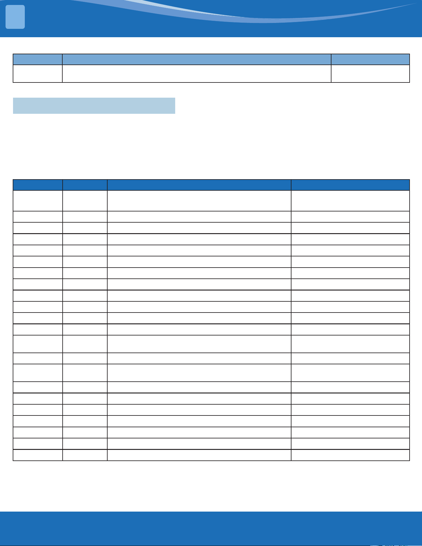
mrcool.com35
Display Error Information Solution
EH b3
Communication malfunction between wire and master control (for KJR-120X/KJR-
120M/KJR-120N series wired controller)
TS34
Error Display on Two Way Communication Wired Controller:
The other error codes displayed on the wire controller are the same from those on the unit.
5.3InformationInquiry&Setting
In order to enter to engineering mode and check the data of the system (data checking mode), please
follow these steps:
• Make sure that the system is in standby status or working in non-locked conditions.
• Press the "Power" + "Fan" buttons together for 7s until the remote controller screen shows "0", and
also "Auto, Cool, Dry, Heat, Battery" icons will be displayed at the same time.
• Press the "UP" or "Down" buttons to choose dierent channel numbers that want to check (from
0-30) on the remote controller, and then the display will show the parameter value.
Channel Code Meaning Remark
0 Error Code
Refer to the next list of error codes
Empty means no error code
1
T1
Room temperature Actual data, °C
2
T2
Indoor coil temperature Actual data, °C
3
T3
Outdoor coil temperature Actual data, °C
4
T4
Ambient temperature Actual data, °C
5
TP
Discharge temperature Actual data, °C
6
FT
Targeted frequency Actual data
7
Fr
Actual frequency Actual data
8
dl
Running current 3.2A-3
9
Ac
AC voltage
10
Sn
Reserved
11
--
Indoor operating mode
12
Pr
Outdoor fan speed
1:low, 2:middle, 3:high, 4:turbo
(OW1/OW2)
13
Lr
EXV opening steps Actual data/8
14
Ir
Indoor fan speed
1:low, 2:middle, 3:high, 4:turbo
(OW1/OW2)
15
Hu
Humidity (if a sensor is there) Actual data, %
16
TT
Set temperature including compensation Actual data, °C
17
nA
Reserved
18
nA
Reserved
19
Uo
Outdoor DC bus voltage
20
oT
Target Frequency calculated by indoor Without limitation
21~30
nA
Reserve
Note:
1. The channel number indicates a certain parameter value (Check next table).
2. The indoor unit display will show the code for 2s and then the parameter value.
3. In the engineering mode, the other keys or operations are invalid except for the following buttons "Power", "Up", "Down", and "Ok".
4. In order to exit from the engineering mode, press the "Power" + "Fan" buttons together for 2s to quit checking and return back to the
home screen
5. The engineering mode will be exited if there is no valid input data for 60s.
TROUBLESHOOTING
5
mrcool.com 36
Error Code of Engineer Mode:
Display Error Information
EH 00
IDU EEPROM malfunction
EH 0A
Indoor EEPROM parameter error
EL 01
IDU & ODU communication error
EH bA
Communication error between indoor unit and indoor external fan module
EH 30
Parameters error of indoor external fan
EH 35
Phase failure of indoor external fan
EH 36
Indoor external fan current sampling bias fault
EH 37
Indoor external fan zero speed failure
EH 38
Indoor external fan stall failure
EH 39
Out of step failure of indoor external fan
EH 3A
Low voltage protection of indoor external fan DC bus
EH 3b
Indoor external fan DC bus voltage is too high fault
EH 3E
Indoor external fan overcurrent fault
EH 3F
Indoor external fan module protection/hardware overcurrent protection
EH 03
IDU fan speed out of control
EC 51
ODU EEPROM parameter error
EC 52
ODU coil temp. sensor (T3) error
EC 53
ODU ambient temp. sensor (T4) error
EC 54
COMP. Discharge temp. sensor (TP) error
EC 55
ODU IPM module temp. sensor (TH) error
EC 0d
Outdoor unit malfunction
EH 60
IDU room temp. sensor (T1) error
EH 61
Evaporator coil temperature sensor T2 is in open circuit or short circuit
EC 71
Outdoor external fan overcurrent fault
EC 75
Outdoor external fan module protection/hardware overcurrent protection
EC 72
Outdoor external fan phase failure
EC 74
Outdoor external fan current sampling bias fault
EC 73
Zero speed failure of outdoor unit DC fan
EC 07
ODU fan speed out of control
EH b5
Intelligent eye communication failure
EL 0C
System lacks refrigerant
EH 0E
Water-level alarm malfunction
EH 0F
Intelligent eye malfunction
FH 07
Communication malfunction between indoor unit and auto-lifting panel
PC 00
ODU IPM module protection
PC 10
Over low voltage protection
PC 11
Over voltage protection
PC 12
DC voltage protection
TROUBLESHOOTING
5
mrcool.com37
Display Error Information
PC 02
Top temperature protection of compressor High temperature protection of IPM module
PC 40
Communication error between outdoor main chip and compressor driven chip
PC 41
Current Input detection protection
PC 42
Compressor start error
PC 43
Lack of phase (3 phase) protection
PC 44
Outdoor unit zero speed protection
PC 45
341PWM error
PC 46
Compressor speed malfunction
PC 49
Compressor over current protection
PC 06
Compressor discharge temperature protection
PC 08
Outdoor current protection
PH 09
Anti-cold air in heating mode
PC 0f
PFC module malfunction
PC 30
System overpressure protection
PC 31
System pressure is too low protection
PC 03
Pressure protection
PC 0L
Outdoor low ambient temperature protection
PH 90
Evaporator coil temperature over high protection
PH 91
Evaporator coil temperature over low protection
PC 0A
Condenser high temperature protection
PH 0C
Indoor unit humidity sensor failure
LH 00
Frequency limit caused by T2
LH 30
Indoor external fan current limit
Lh 31
Indoor external fan voltage limit
LC 01
Frequency limit caused by T3
LC 02
Frequency limit caused by TP
LC 05
Frequency limit caused by voltage
LC 03
Frequency limit caused by current
LC 06
Frequency limit caused by PFC
LC 30
Frequency limit caused by high pressure
LC 31
Frequency limit caused by low pressure
LH 07
Frequency limit caused by remote controller
----
IDUs comm. conict (match with multi outdoor unit)
NA
No malfunction and protection
TROUBLESHOOTING
5

mrcool.com 38
In order to enter to the engineering mode and check the advanced function settings please follow
these steps.
If you want to check the current functions set value (Presetting Page):
1. First, you will need to disconnect the power supply from the unit and wait 1 minute.
2. Then re-connect the power supply to the unit and it should enter standby mode.
3. Press the "Power" + "Fan" buttons together for 7s until the remote controller screen shows "0",
then the "Auto, Cool, Dry, Heat, Battery" icons will be displayed at the same time.
4. Press "UP" or "Down" buttons to choose dierent channel numbers that you want to check (from
0-30) on the remote controller.
5. The press the "Power" button for 2s until the remote controller screen shows "Ch".
6. Press the "OK" button to query the current function set value while the remote controller shows
"Ch" and the function set vale will be shows on the indoor units display.
If you want to change the current functions set value:
1. First, you will need to disconnect the power supply form the unit and wait 1 minute.
2. Then connect the power supply again to the unit and it should enter standby mode.
3. Press the "Power" + "Fan" buttons together for 7s until the remote controller screen shows "0" then
the "Auto, Cool, Dry, Heat, Battery" icons will be displayed at the same time.
4. Press the "UP" or "Down" buttons to choose dierent channel numbers that you want to change
(from 0~30) on the remote controller.
5. The press the "Power" button for 2s until the remote controller screen shows "Ch".
6. Press the "Up" or "Down" button to choose the desired set value from the screen of the remote
control.
7. The press "OK" to send the new set value to the indoor unit, the indoor will display "CS" which
means that the new set value is uploaded successfully.
8. Finally, disconnect the power supply again from the unit and wait for 10 minutes then re-connect.
Note:
1. The channel number indicates a certain function and each number will be showed on the indoor
units screen indicates the current function set value (Check the table following table).
2. In the engineering mode the other keys or operations are invalid except for the following buttons
"Power", "Up", "Down", and "OK".
3. I order to set a new set value successfully you need to nish the steps (from 2 to 7) within 1 minute
only.
4. The engineering mode will be exited if there is no valid input data for 60s.
5. In order to exit from the engineering mode please follow these steps.
• Press the "Power" button for 2s until the remote controller screen shows "0".
• The press the "Power" + "Fan" buttons together for 2s to quit the engineering mode and back to
the home screen.
Advanced Function Setting:
TROUBLESHOOTING
5
mrcool.com39
Channel Function Parameter Value Meaning Remark
0 Capacity setting (Btu/h) 1-100K
1 Auto-restart function
0- Inactive
1- Active
24V control is invalid
2 Fan control when Ts reached
1- Fan stop
2- Fan runs at lowest RPM
3- Fan runs at setting RPM
4- Fan stops for 4 mins and runs for 1 min
5- Fan stops for 8 mins and runs for 1 min
6- Fan stops for 16 mins and runs for 1 min
7- Fan stops for 24 mins and runs for 1 min
8- Fan stops for 48 mins and runs for 1 min
9- Fan stops for 15 mins and runs for 2.5 mins
10- Fan stops for 30 mins and runs for 2.5 mins
11- Fan stops for 60 mins and runs for 2.5 mins
12- Fan runs at setting RPM, but stops if automatic speed
is chosen
13- Fan runs at lowest speed, but stops if automatic speed
is chosen
24V control is invalid
3 Mode lock
CH- Cooling and heating (all modes)
CC- Cooling only (Cooling + Drying + Fan only)
Remote controller will change as well.
4 Lowest setting temperature 16-24
Remote controller will change as well.
24V control is invalid
5 Highest setting temperature 25-30
Remote controller will change as well.
24V control is invalid
6 Reserved Nothing to set
7 / Nothing to set
8 / Nothing to set
9 / Nothing to set
10 / Nothing to set
11
Min. frequency limitation in
cooling mode
10,11,12,..., 49,50,-- (cancel) Single indoor unit is invalid
12
Min. frequency limitation in
heating mode
20,21,22,...,49,50,-- (cancel) Single indoor unit is invalid
13 / Nothing to set
14 / Nothing to set
15
Frequency selection of
outdoor forced-operation
10,11,12,...,249,250,-- (cancel) Single indoor unit is invalid
16 One button reset rS- Reset
17 nA Nothing to set
18 / Nothing to set
19
Max. frequency selection in
cooling mode
40,41,42,..,83,84,-- (cancel) Single indoor unit is invalid
20 / Nothing to set Without limitation
21
Cooling temperature
compensation
-3.0,-2.5,-2.0,...,3.0,3.5,-- (cancel) 24V control is invalid
22
Heating temperature
compensation
-6.5,-6.0,-5.5,...,0.5,1.0,1.5,...,7.0,7.5,-- (cancel) 24V control is invalid
23 Reserved Nothing to set
TROUBLESHOOTING
5
mrcool.com 40
Channel Function Parameter Value Meaning Remark
24 Reserved Nothing to set
25 Reserved Nothing to set
26 Reserved Nothing to set
27 Defrosting type
A0- Normal defrosting
A1- Enhanced defrosting
Single indoor unit is invalid
28 Reserved Nothing to set
29 Reserved Nothing to set
30 Reserved Nothing to set
5.4 Error Diagnosis Without Error Code
Remote Maintenance:
Suggestion: When troubles occur, please check the following points with the customer before eld maintenance.
No. Problem Solution
1 Unit will not start TS14-TS15
2 The power switch is on but fans will not start TS14-TS-15
3 The temperature on the display board cannot be set TS14-TS-15
4 Unit is on but the air is not cold/hot TS14-TS-15
5 Unit runs but shortly stops TS14-TS-15
6 The unit starts up and stops frequently TS14-TS-15
7 Unit runs continuously but insucient cooling/heating TS14-TS-15
8 Cool cannot change to heat TS14-TS-15
9 Unit is noisy TS14-TS-15
Field Maintenance:
No. Problem Solution
1 Unit will not start TS16-TS17
2 Compressor will not start but fans run TS16-TS17
3 Compressor and condenser fan will not start TS16-TS17
4 Air handler fan will not start TS16-TS17
5 Condenser fan will not start TS16-TS17
6 Unit runs but shortly stops TS16-TS17
7 Compressor short-cycles due to overload TS16-TS17
8 High suction pressure TS16-TS17
9 Low discharge pressure TS16-TS17
10 High suction pressure TS16-TS17
11 Low suction pressure TS16-TS17
12 Unit runs continuously but insucient cooling TS16-TS17
13 Too cool TS16-TS17
14 Compressor is noisy TS16-TS17
15 Horizontal louver cannot revolve TS16-TS17
TROUBLESHOOTING
5
mrcool.com41
1. Remote
Maintenance
Electrical Circuit Refrigerant Circuit
Possible causes of
trouble
Power failure
The main power tripped
Loose connections
Faulty transformer
The voltage too high or too low
Theremotecontrolispoweredo
Broken the remote control
Dirtyairlter
Dirtycondenserns
Thesettingtemperatureishigher/lower
thantheroom's(cooling/heating)
Theambienttemperatureistoohigh/
lowwhenthemodeiscooling/heating
Fan mode
Silence function is activate
Frostinganddefrostingfrequency
Unit will not start √ √ √ √ X X X X X X X X X X
The power switch is
on but fans will not
start
X X √ √ √ X X X X X X X X X
The temperature
on the playboard
cannot be set
X X X X X √ √ X X X X X X X
Unit is on but the air
is not cold/hot
X X X X X X X X X √ √ √ X X
Unit runs but shortly
stops
X X X X √ X X X √ √ X X X
The unit startup and
stops frequently
X X X X √ X X X X X √ X X √
Unit runs
continuously but
insucient cooling/
heating
X X X X X X X √ √ √ √ X √ X
Cool cannot change
to heat
X X X X X X X X X X X X X X
Unit is noisy X X X X X X X X X X X X X X
Testmethod/
remedy
Test voltage
Close the power switch
Inspect connections - tighten
Change the transformer
Test voltage
Replace the battery of the
remote control
Replace the remote control
Clean or replace
Clean
Adjustthesettingtemperature
Turn on the unit later
Adjusttocoolmode
Turnothesilencefunction
Turn on the unit later
TROUBLESHOOTING
5
mrcool.com 42
1. Remote
Maintenance
Others
Possible causes of
trouble
Heavy load condition
Loosen hold down bolts or screws
Bad airproof
The air inlet or outlet of either unit is
blocked
Interference from cell phone towers and
remote boosters
Shipping plates remain attached
Unit will not start X X X X X X
The power switch is
on but fans will not
start
X X X X √ X
The temperature
on the playboard
cannot be set
X X X X X X
Unit is on but the air
is not cold/hot
X X X X X X
Unit runs but shortly
stops
X X X X X X
The unit startup and
stops frequently
X X X √ X X
Unit runs
continuously but
insucient cooling/
heating
√ X √ √ X X
Cool cannot change
to heat
X X X X X X
Unit is noisy X √ X X X √
Testmethod/
remedy
Check heat load
Tighten bolts and screws
Close all windows and doors
Remove the obstacles
Reconnect the power or press
ON/OFFbuttonontheremoteto
restart operation
Remove item
TROUBLESHOOTING
5
mrcool.com43
2. Field
Maintenance
Refrigerant Circuit Others
Possible
causes of
trouble
Compressor stuck
Shortage of refrigerant
Restrictedliquidline
Dirtyairlter
Dirty evaporator coil
Insucientairthrough
evaporator coil
Overcharge of refrigerant
Dirty or partially blocked
condenser
Air or incompressible gas in
refrigerant cycle
Short cycling of condensing air
High temperature condensing
medium
Insucientcondensingmedium
Broken compressor internal parts
Inecientcompressor
Expansion valve obstructed
Expansion valve or capillary tube
close completely
Leaking power element on
expansion valve
Poor installation of feeler bulb
Heavy load condition
Loosenholddownboltsand/or
screws
Shipping plates remain attached
Poor choices of capacity
Contact of piping with other
piping or external plate
Unit will not
start
X X X X X X X X X X X X X X X X X X X X X X X
Compressor
will not start
but fans run
√ X X X X X X X X X X X X X X X X X X X X X X
Compressor
and condenser
fan will not
start
X X X X X X X X X X X X X X X X X X X X X X X
Air handler fan
will not start
X X X X X X X X X X X X X X X X X X X X X X X
Condenser fan
will not start
X X X X X X X X X X X X X X X X X X X X X X X
Unit runs but
shortly stops
X √ √ X X X √ √ X X X X X X X √ √ X X X X X X
Compressor
short-cycles
due to overload
X √ X X X X √ √ X X X X X X X X X X X X X X X
High discharge
pressure
X X X X X X √ √ √ √ √ √ X X X X X X X X X X X
Low discharge
pressure
X √ X X X X X X X X X X X √ X X X X X X X X X
Testmethod/
remedy
Replace the compressor
Leak test
Replace restricted part
Clean or replace
Clean coil
Check fan
Change charged refrigerant
volume
Clean condenser or remove
obstacle
Purge, evacuate and recharge
Removeobstructiontoairow
Remove obstruction in air or
waterow
Remove obstruction in air or
waterow
Replace compressor
Testcompressoreciency
Replace valve
Replace valve
Replace valve
Fix feeler bulb
Check heat load
Tighten bolts or screws
Remove them
Choose system of larger capacity
or add another system
Rectify piping so as to not contact
with each other or with external
plate
TROUBLESHOOTING
5
mrcool.com 44
TROUBLESHOOTING
5
2. Field
Maintenance
Refrigerant Circuit Others
Possible causes of
trouble
Compressor stuck
Shortage of refrigerant
Restrictedliquidline
Dirtyairlter
Dirty evaporator coil
Insucientairthroughevaporator
coil
Overcharge of refrigerant
Dirty or partially blocked condenser
Air or incompressible gas in
refrigerant cycle
Short cycling of condensing air
High temperature condensing
medium
Insucientcondensingmedium
Broken compressor internal parts
Inecientcompressor
Expansion valve obstructed
Expansion valve or capillary tube
close completely
Leaking power element on
expansion valve
Poor installation of feeler bulb
Heavy load condition
Loosenholddownboltsand/or
screws
Shipping plates remain attached
Poor choices of capacity
Contact of piping with other piping
or external plate
High suction
pressure
X X X X X X √ X X X X X X √ X X X √ √ X X X X
Low suction
pressure
X √ √ √ √ √ X X X X X X X X √ √ √ X X X X X X
Unit runs
continuously but
insucient cooling
X √ √ √ √ √ X √ √ √ X X X √ X X X X √ X X √ X
Too Cool X X X X X X X X X X X X X X X X X X X X X X X
Compressor is
noisy
X X X X X X √ X X X X X √ X X X X X X √ √ X √
Horizontal louver
cannot revolve
X X X X X X X X X X X X X X X X X X X X X X X
Testmethod/
remedy
Replace the compressor
Leak test
Replace restricted part
Clean or replace
Clean coil
Check fan
Change charged refrigerant volume
Clean condenser or remove obstacle
Purge, evacuate and recharge
Removeobstructiontoairow
Removeobstructioninairorwaterow
Removeobstructioninairorwaterow
Replace compressor
Testcompressoreciency
Replace valve
Replace valve
Replace valve
Fix feeler bulb
Check heat load
Tighten bolts or screws
Remove them
Choose system of larger capacity or add
another system
Rectify piping so as to not contact with
each other or with external plate
mrcool.com45
TROUBLESHOOTING
5
2. Field
Maintenance
Electrical Circuit
Possible causes of
trouble
Power Failure
Blown fuse or varistor
Loose connections
Shorted or broken wires
Safety device opens
Faultythermostat/room
temperature sensor
Wrong setting place of
temperature sensor
Faulty transformer
Shorted or open capacitor
Faulty magnetic contactor for
compressor
Faulty magnetic contactor for fan
Low voltage
Faulty stepping motor
Shorted or grounded compressor
Shorted or grounded fan motor
Unit will not start √ √ √ √ √ X X √ X X X X X X X
Compressor will
not start but fans
run
X X X √ X √ X √ √ X X X X √ X
Compressor and
condenser fan will
not start
X X X √ X √ X X X √ X X X X X
Air handler fan will
not start
X X X √ X X X X √ X √ X X X √
Condenser fan will
not start
X X X √ X √ X X √ X √ X X X √
Unit runs but
shortly stops
X X X X X X X X X √ X √ X X X
Compressor
short-cycles due to
overload
X X X X X X X X X √ X √ X X X
High discharge
pressure
X X X X X X X X X X X X X X X
Low discharge
pressure
X X X X X X X X X X X X X X X
Testmethod/
remedy
Test voltage
Inspect fuse type & size
Inspect connections - tighten
Test circuits with tester
Test continuity of safety device
Testcontinuityofthermostat/sensor
& wiring
Place the temperature sensor at the
central of the air inlet grille
Check control circuit with tester
Check capacitor with tester
Test continuity of coil & contacts
Test continuity of coil & contacts
Test voltage
Replace the stepping motor
Check resistance with multimeter
Check resistance with multimeter
mrcool.com 46
TROUBLESHOOTING
5
2. Field
Maintenance
Electrical Circuit
Possible causes of
trouble
Power Failure
Blown fuse or varistor
Loose connections
Shorted or broken wires
Safety device opens
Faultythermostat/room
temperature sensor
Wrong setting place of temperature
sensor
Faulty transformer
Shorted or open capacitor
Faulty magnetic contactor for
compressor
Faulty magnetic contactor for fan
Low voltage
Faulty stepping motor
Shorted or grounded compressor
Shorted or grounded fan motor
High suction
pressure
X X X X X X X X X X X X X X X
Low suction
pressure
X X X X X X X X X X X X X X X
Unit runs
continuously but
insucient cooling
X X X X X X X X X X X X X X X
Too cool X X X X X X √ √ X X X X X X X
Compressor is
noisy
X X X X X X X X X X X X X X X
Horizontal louver
can not revolve
X X √ √ X X X X X X X X √ X X
Testmethod/
remedy
Test voltage
Inspect fuse type & size
Inspect connections - tighten
Test circuits with tester
Test continuity of safety device
Testcontinuityofthermostat/sensor
& wiring
Place the temperature sensor at the
central of the air inlet grille
Check control circuit with tester
Check capacitor with tester
Test continuity of coil & contacts
Test continuity of coil & contacts
Test voltage
Replace the stepping motor
Check resistance with multimeter
Check resistance with multimeter
mrcool.com47
TROUBLESHOOTING
5
5.5 Quick Maintenance by Error Code
If you do not have the time to test which specic parts are faulty, you can change the required parts according to
the error code. You can nd the parts to replace by error code in the following table.
PartRequiring
Replacement
Error Code
EH00/
EH 0A
EL 01 EH 03 EH 60 EH 61 EL 0C
EHC1/
EH C2
EH 0E EH 0b
Indoor PCB √ √ √ √ √ √ X √ √
Outdoor PCB X √ X X X X X X X
Indoor Fan Motor X X √ X X X X X X
T1 Sensor X X X √ X X X X X
T2 Sensor X X X X √ √ X √ X
T2B Sensor X X X X X X X X X
T2A sensor X X X X X X X X X
Magnet Ring X √ X X X X X X X
Compressor X X X X X X X X X
Additional Refrigerant X X X X X √ √ √ X
Water-Level Switch X X X X X X X √ X
Water Pump X X X X X X X √ X
Display Board X X X X X X X X √
PartRequiring
Replacement
Error Code
EC 54 EC 51 EC 52 EC 53 EC 56 EC 07 PC 00 PC 01 PC 02 PC 04 PC 03
FH
CC/
EH C3
Indoor PCB X X X X X X X X X X X √
Outdoor PCB √ √ √ √ √ √ √ √ √ √ √ X
Outdoor Fan Motor X X X X X √ √ X √ √ X X
T3 Sensor X X √ X X X X X X X X X
T4 Sensor X X X √ X X X X X X X X
TP Sensor √ X X X X X X X X X X X
T2B Sensor X X X X √ X X X X X X X
Refrigerant Sensor X X X X X X X X X X X √
Reactor Sensor X X X X X X X √ X X X X
Compressor X X X X X X √ X X √ X X
IPM Module Board X X X X X X √ √ √ √ X X
Pressure Protector X X X X X X X X X X √ X
Additional
Refrigerant
X X X X X X X X X X √ X
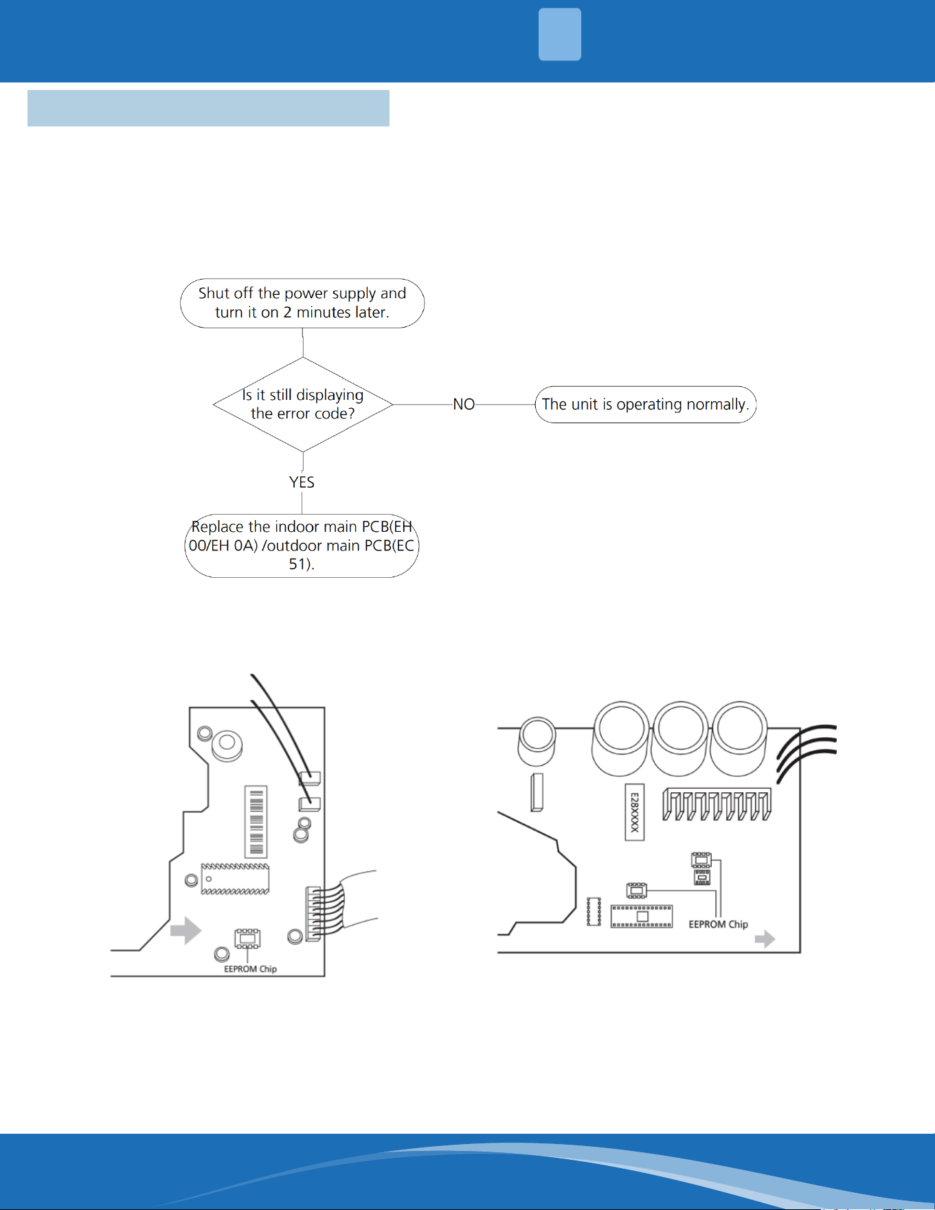
mrcool.com 48
TROUBLESHOOTING
5
5.6 Troubleshooting by Error Code
EH00/EH0A/EC51:EEPROMMalfunctionErrorDiagnosisandSolution.
Description: Indoor PCB main chip does not receive feedback from EEPROM chip.
Recommended parts to prepare:
• Indoor PCB
• Outdoor PCB
Troubleshooting and repair:
Remarks:
EEPROM: A read-only memory whose contents can be erased and reprogrammed using a puled
voltage. The location of the EEPROM chip on the indoor PCB is shown in the following images:
Note: These pictures are for reference, actual appearance may vary.
Troubleshooting and repair of the compressor driven chip EEPROM parameter error and
communication error between the outdoor main chip and compressor driven chip are the same
as EC 51.
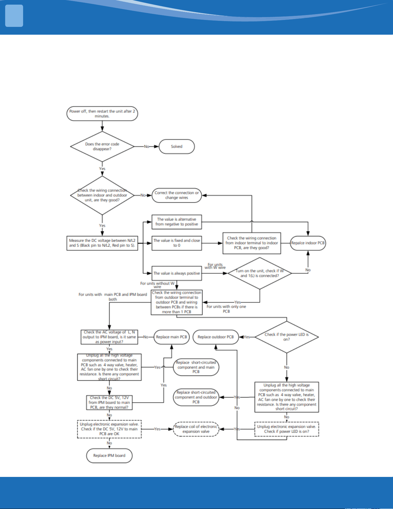
mrcool.com49
TROUBLESHOOTING
5
EL 01: IDU & ODU Communication Error Diagnosis and Solution.
Description: Indoor unit cannot communicate with the outdoor unit.
Recommended parts to prepare:
• Indoor PCB
• Outdoor PCB
• Reactor
Troubleshooting and repair:
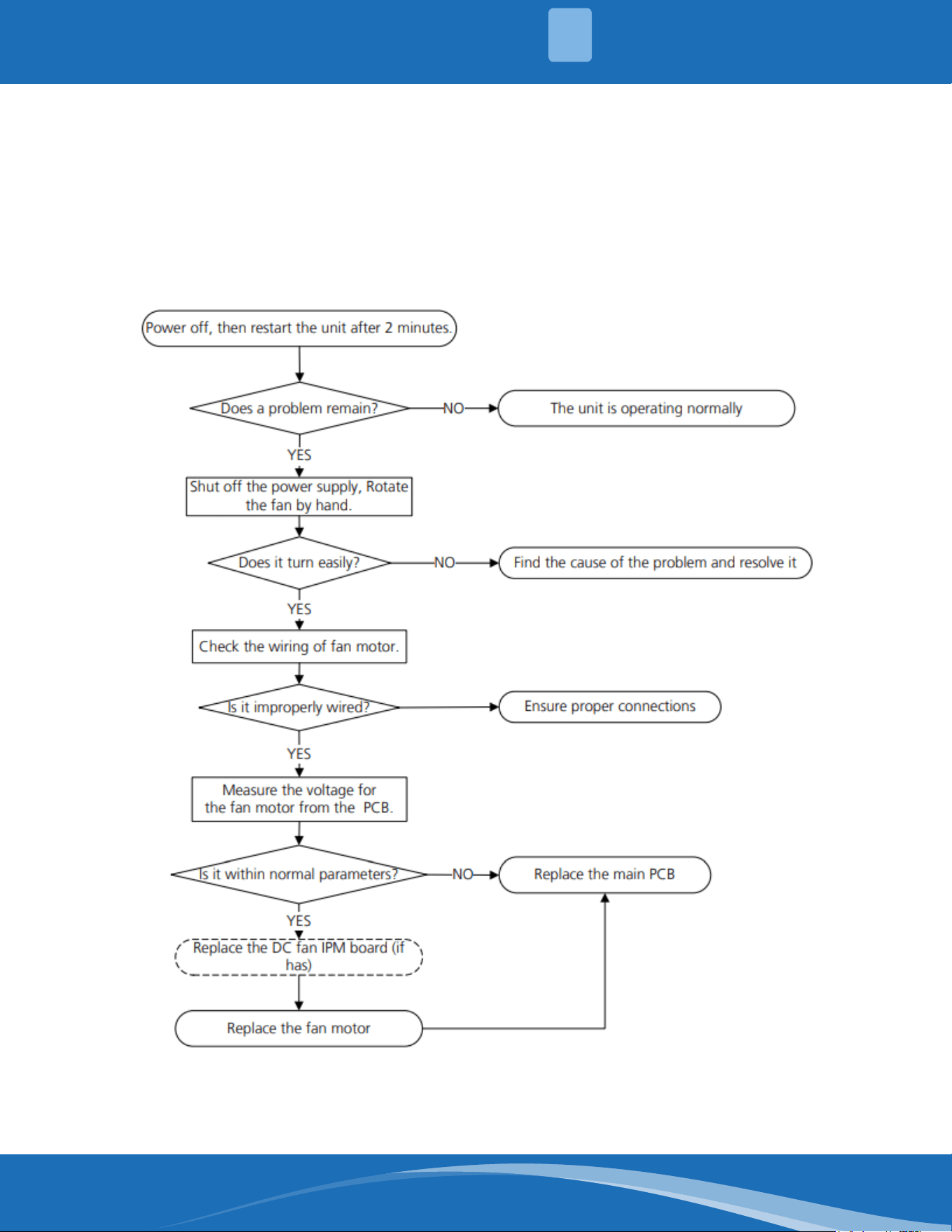
mrcool.com 50
TROUBLESHOOTING
5
EH03/EC07:FanSpeedOutofControlDiagnosisandSolution.
Description: When the indoor/outdoor fan speed keeps too low or too high for a certain time, the unit
ceases operation and the LED displays a fault.
Recommended parts to prepare:
• Connection wires
• Fan assembly
• Fan motor
• PCB
Troubleshooting and repair:
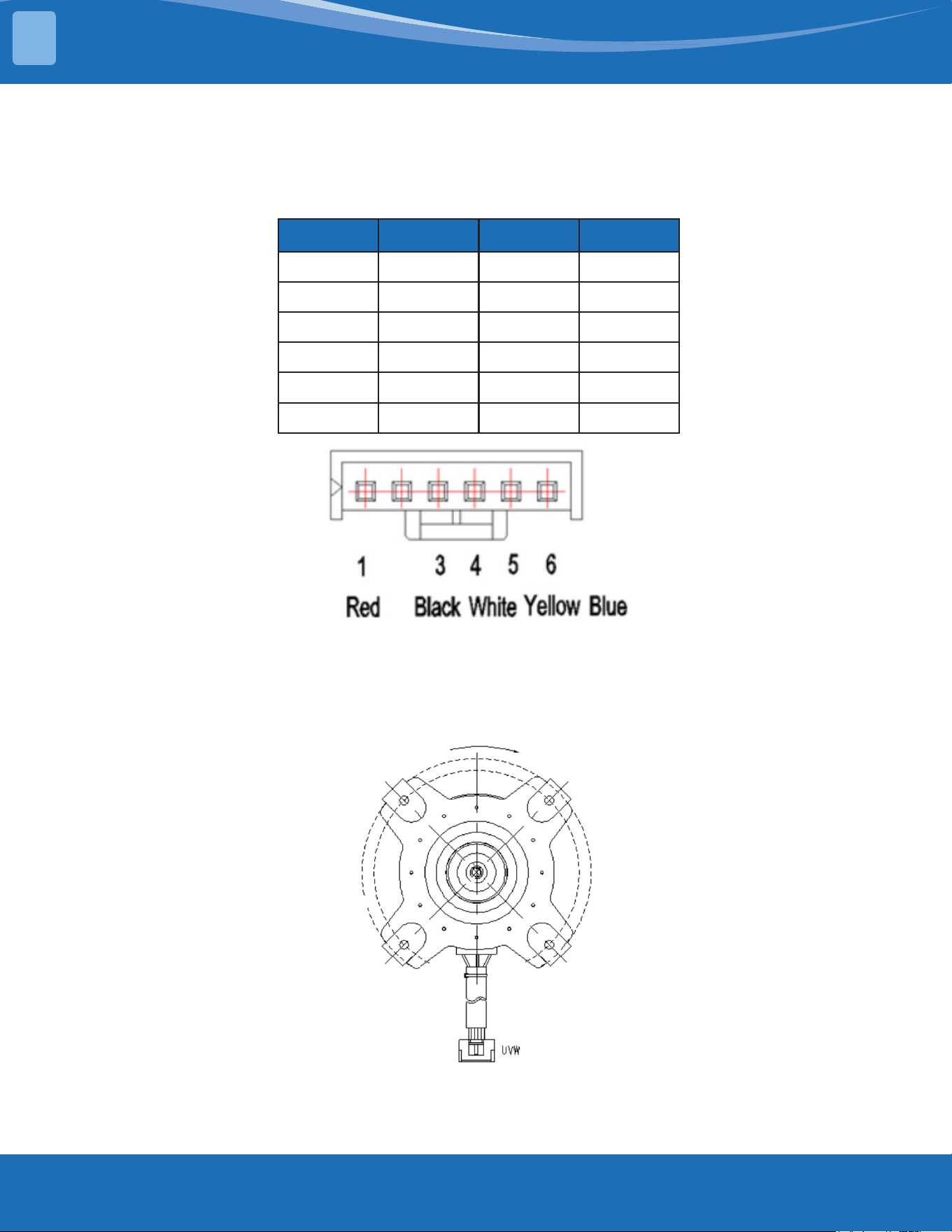
mrcool.com51
TROUBLESHOOTING
5
Index:
1. Indoor or Outdoor DC fan motor (control chip is in fan motor)
Power on and make sure the unit is in standby, measure the voltage of pin1-pin3, pin4-pin3 on the fan
motor connector. If the value of the voltage is not in the range showing in the tables below the PCB
will have problems and will need to be replaced.
NO. Color Signal Voltage
1 Red Vs/Vm 192V~380V
2 --- --- ---
3 Black GND 0V
4 White Vcc 13.5-16.5V
5 Yellow Vsp 0~6.5V
6 Blue FG 13.5-16.5V
Index:
1. Outdoor DC fan motor (control chip is in outdoor PCB)
Release the UVW connector and measure the resistance of U-V, U-W, V-W. If the resistance is not equal
to each other the fan motor has a problem and needs to be replaced. Otherwise the PCB has a
problem and needs to be replaced.
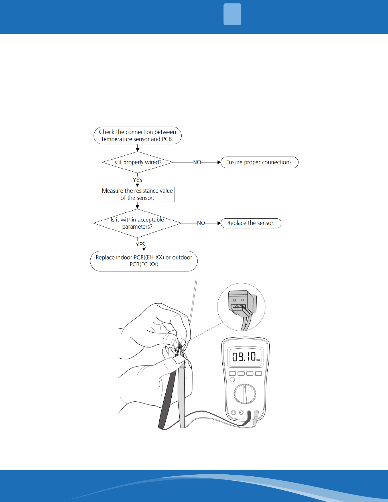
mrcool.com 52
TROUBLESHOOTING
5
EH60/EH61/EC53/EC52/EC54/EC56:OpenCircuitorShortCircuitof
Temperature Sensor Diagnosis and Solution.
Description: If the sampling voltage is lower than 0.06V or higher than 4.94V, the LED displays a fault
code.
Recommended parts to prepare:
• Connection wires
• Sensors
• PCB
Troubleshooting and repair:
Note: The picture and the value are for reference only, actual condition and specic values may vary.
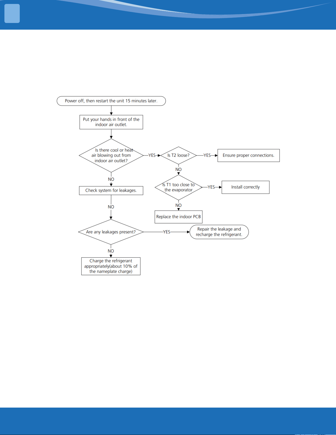
mrcool.com53
TROUBLESHOOTING
5
EL 0C: System Lacks Refrigerant Diagnosis and Solution.
Description: Judging the abnormality of the refrigeration system according to the number of
compressor stops and the changes in operating parameters caused by excessive exhaust temperature.
Recommended parts to prepare:
• Indoor PCB
• Additional refrigerant
Troubleshooting and repair:
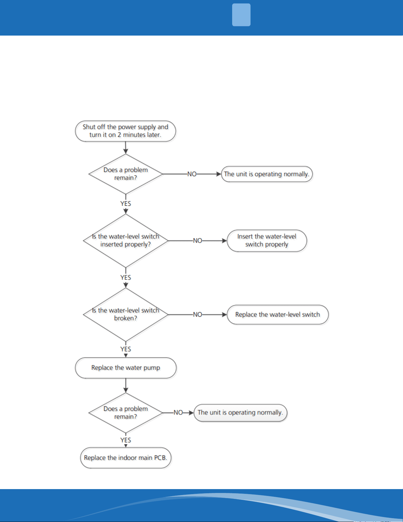
mrcool.com 54
TROUBLESHOOTING
5
EH 0E: Water-Level Alarm Malfunction Diagnosis and Solution.
Description: If the sampling voltage is not 5V, the LED displays a fault code.
Recommended parts to prepare:
• Connection wires
• Water-level switch
• Water pump
• Indoor PCB
Troubleshooting and repair:
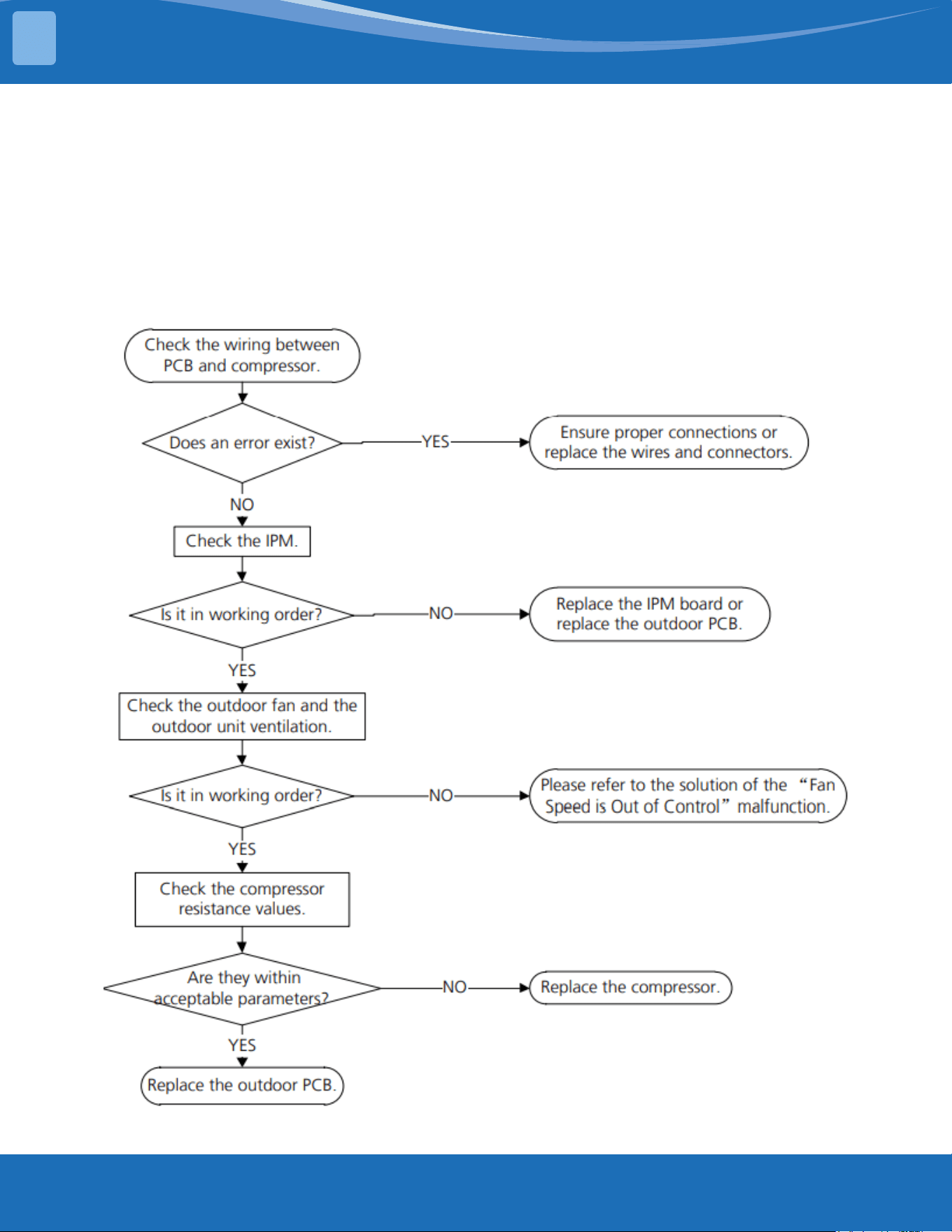
mrcool.com55
TROUBLESHOOTING
5
PC 00: ODU IPM Module Protection Diagnosis and Solution.
Description: When the voltage signal the IPM sends to the compressor drive chip is abnormal, the LED
displays a fault code.
Recommended parts to prepare:
• Connection wires
• IPM module board
• Outdoor fan assembly
• Compressor
• Outdoor PCB
Troubleshooting and repair:
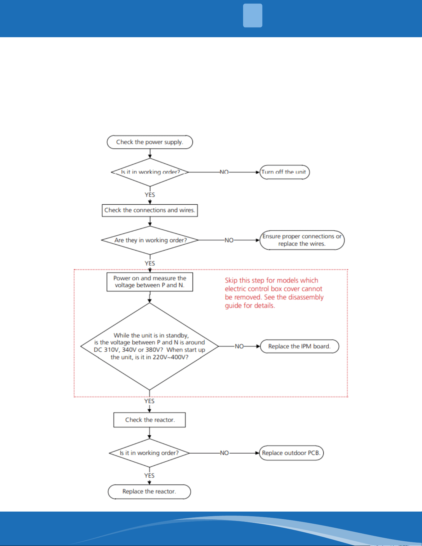
mrcool.com 56
TROUBLESHOOTING
5
PC 01: ODU Voltage Protection Diagnosis and Solution.
Description: Abnormal increases or decreases in voltage are detected by checking the specied
voltage detection circuit.
Recommended parts to prepare:
• Power supply wires
• IPM module board
• PCB
• Reactor
Troubleshooting and repair:
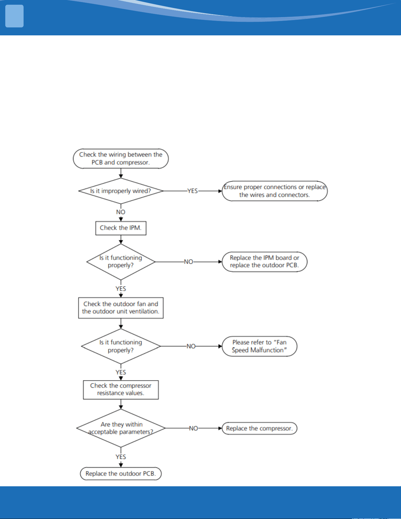
mrcool.com57
TROUBLESHOOTING
5
PC 04: Inverter Compressor Drive Error Diagnosis and Solution.
Description: An abnormal inverter compressor drive is detected by a special detection circuit,
including communication, signal detection, voltage detection, compressor rotation speed signal
detection, and so on.
Recommended parts to prepare:
• Connection wires
• IPM module board
• Outdoor fan assembly
• Compressor
• Outdoor PCB
Troubleshooting and repair:
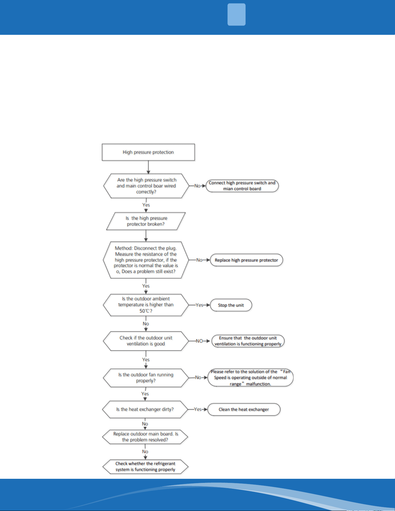
mrcool.com 58
TROUBLESHOOTING
5
PC 03: Pressure Protection (Low or High Pressure) Diagnosis and Solution.
Description: The outdoor pressure switch cut o the system due to high pressure (if pressure is
higher than 638 PSI.(4.4MPa)). Or the outdoor pressure switch cut o the system due to low pressure
(if the pressure is lower than 18.85 PSI.(0.13MPa) the LED will display a fault code.
Recommended parts to prepare:
• Connection wires
• Pressure switch
• Outdoor fan
• Outdoor main PCB
• Refrigerant
Troubleshooting and repair:
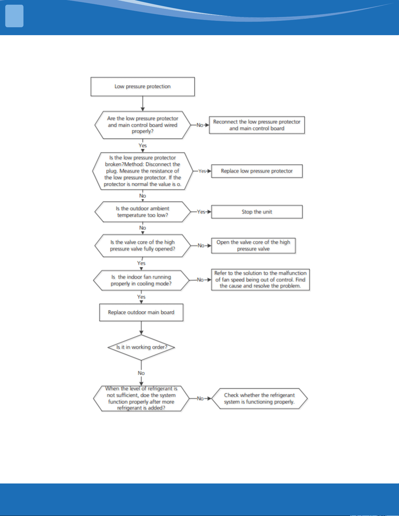
mrcool.com59
TROUBLESHOOTING
5
PC 03: Cont.
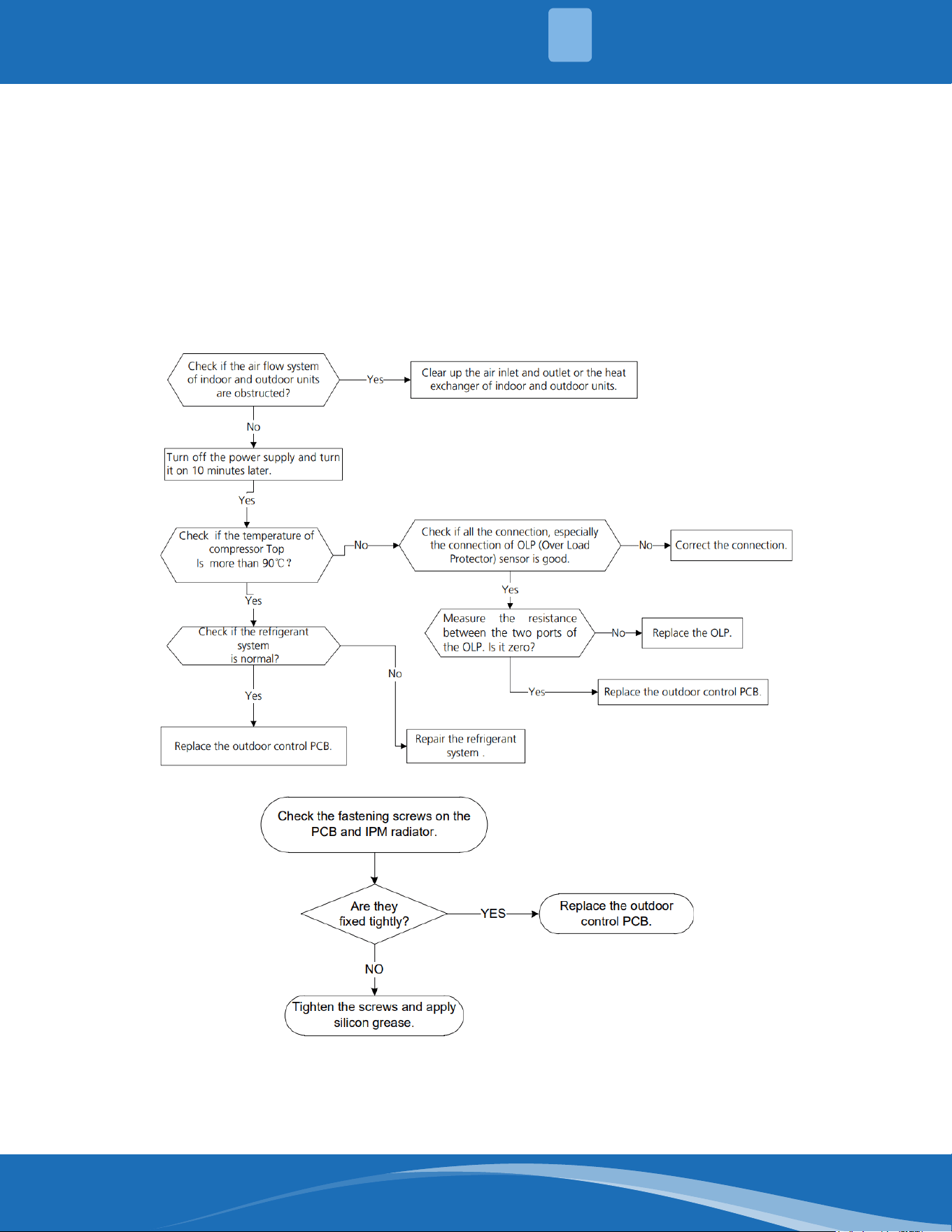
mrcool.com 60
TROUBLESHOOTING
5
PC 02: Compressor Top (or IPM) Temp. Protection Diagnosis and Solution.
Description: (For some models with overload protection). If the sampling voltage is not 5V, the LED
will display a fault code. If the temperature of the IPM module is higher than a certain value, the LED
will display a fault code.
Recommended parts to prepare:
• Connection wires
• Outdoor PCB
• IPM module board
• High pressure protector
• System blockages
Troubleshooting and repair:
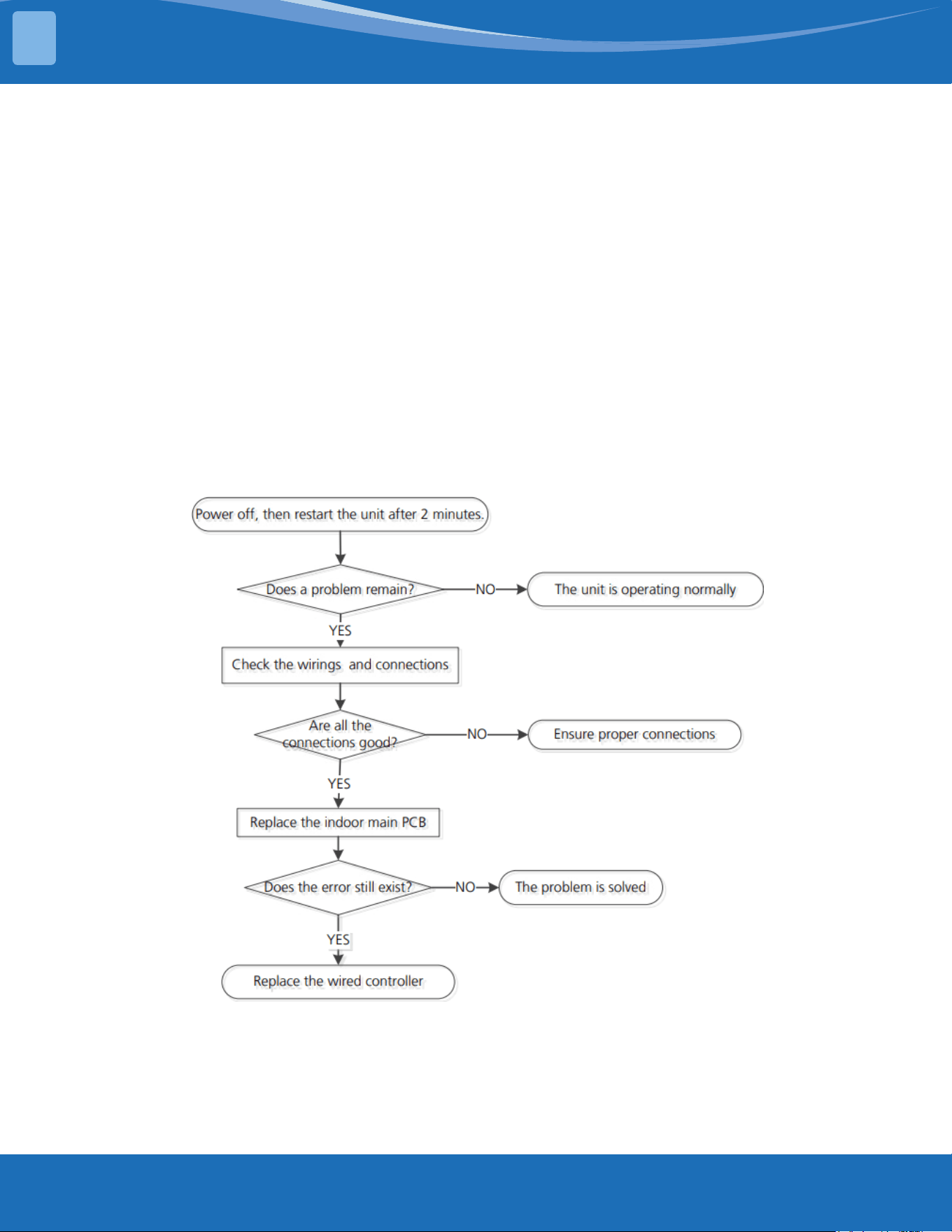
mrcool.com61
TROUBLESHOOTING
5
PC 0L: Low Ambient Temperature Protection.
Description: It is a protection function. When the compressor is o and the outdoor ambient
temperature (T4) is lower than -35°C for 10s, the AC will stop and display the fault code.
When the compressor is on and the outdoor ambient temperature (T4) is lower than -40°C for 10s, the
AC will stop and display the fault code.
When the outdoor ambient temperature (T4) is no lower than -32°C for 10s, the unit will exit the
protection.
EH b3: Communication malfunction Between Wire and Master Control Diagnosis
and Solution.
Description: If the indoor PCB does not receive feedback from the wired controller, the error displays
on the wired controller..
Recommended parts to prepare:
• Connection wires
• Indoor PCB
• Wired Controller
Troubleshooting and repair:
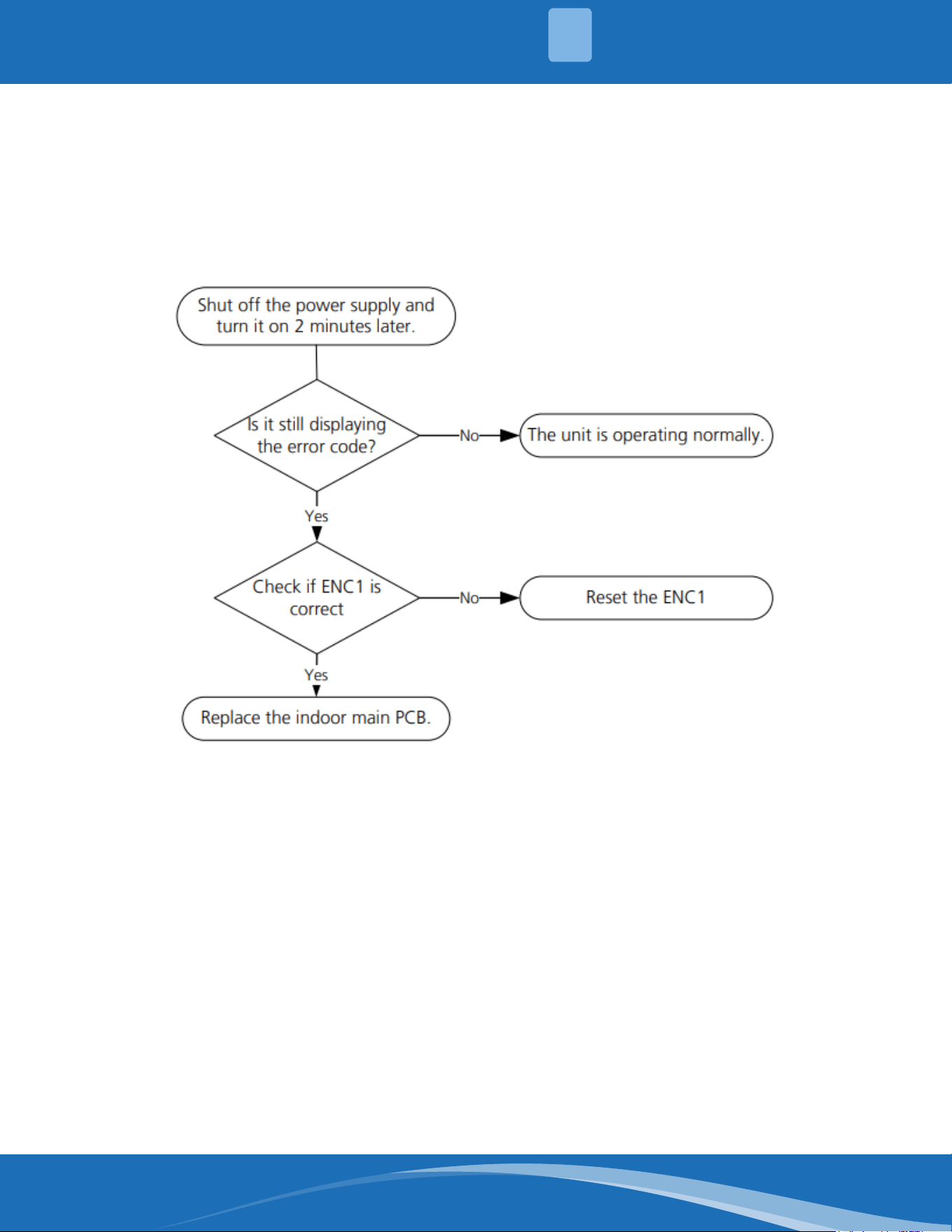
mrcool.com 62
TROUBLESHOOTING
5
EH bA: Communication Error Between the Indoor Unit and the External Fan
module/EH3A:ExternalFanDCBusVoltageistooLowProtection/EH3b:External
fan DC bus voltage is too High Fault Diagnosis and Solution.
Description: The indoor unit does not receive the feedback from the external fan module during 150s
or the indoor unit receives abnormal increases or decreases in voltage from the external fan module.
Recommended parts to prepare:
• Indoor main PCB
Troubleshooting and repair:
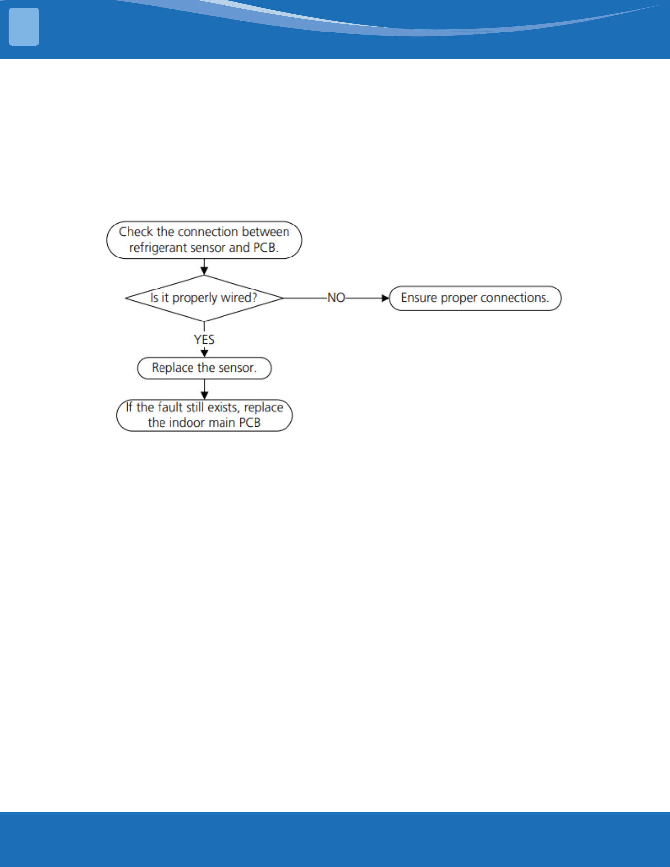
mrcool.com63
TROUBLESHOOTING
5
FHCC:RefrigerantSensorError/EHC3:RefrigerantSensorisOutofRange
Diagnosis and Solution.
Description: Indoor unit receives a fault signal for 10s or the indoor unit does not receive feedback
from the refrigerant sensor for 150s.
Recommended parts to prepare:
• Connection wires
• Sensors
• Indoor man PCB
Troubleshooting and repair:
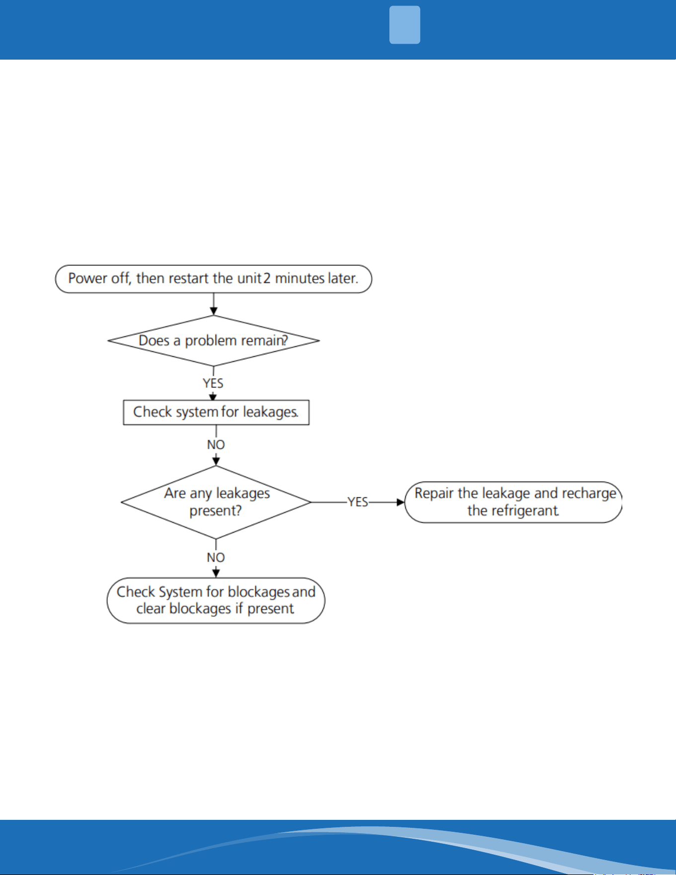
mrcool.com 64
TROUBLESHOOTING
5
EHC1:RefrigerantSensorDetectsLeakage/EHC2:RefrigerantSensorisOutof
Range and Leakage is Detected Diagnosis and Solution
Description: The refrigerant sensor detects a concentration higher than or equal to 10%*LFL for 10
seconds or the refrigerant sensor detects a concentration higher than or equal to 20%*LFL or the multi
model receives the refrigerant leakage protection fault sent by the outdoor unit.
Multi-zone: Only the buzzer of the indoor unit that detects refrigerant leakage continues to sound the
alarm, the shortest sound is 10 seconds and the longest sound is 5 minutes (you can press any key
on the remote control, wired controller, APP, and so on to eliminate the alarm) and any other non-
refrigerant leakage fault the indoor unit will only display ECC1 and the buzzer will not make a sound.
Recommended parts to prepare:
• Additional refrigerant
Troubleshooting and repair:
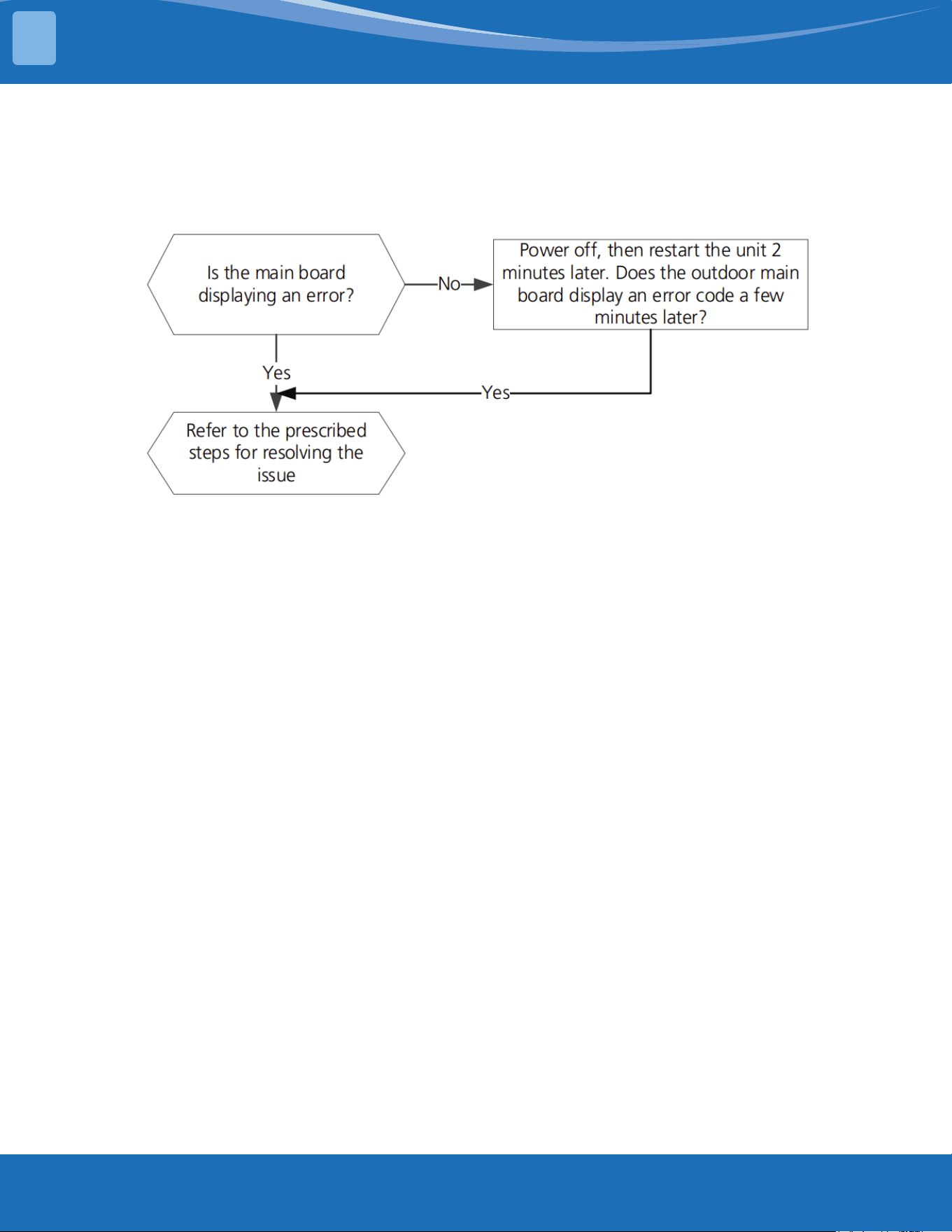
mrcool.com65
TROUBLESHOOTING
5
EC 0d: ODU malfunction diagnosis and solution.
Description: The indoor unit detect the outdoor is having an error.
Recommended parts to prepare:
• Outdoor unit
Troubleshooting and repair:
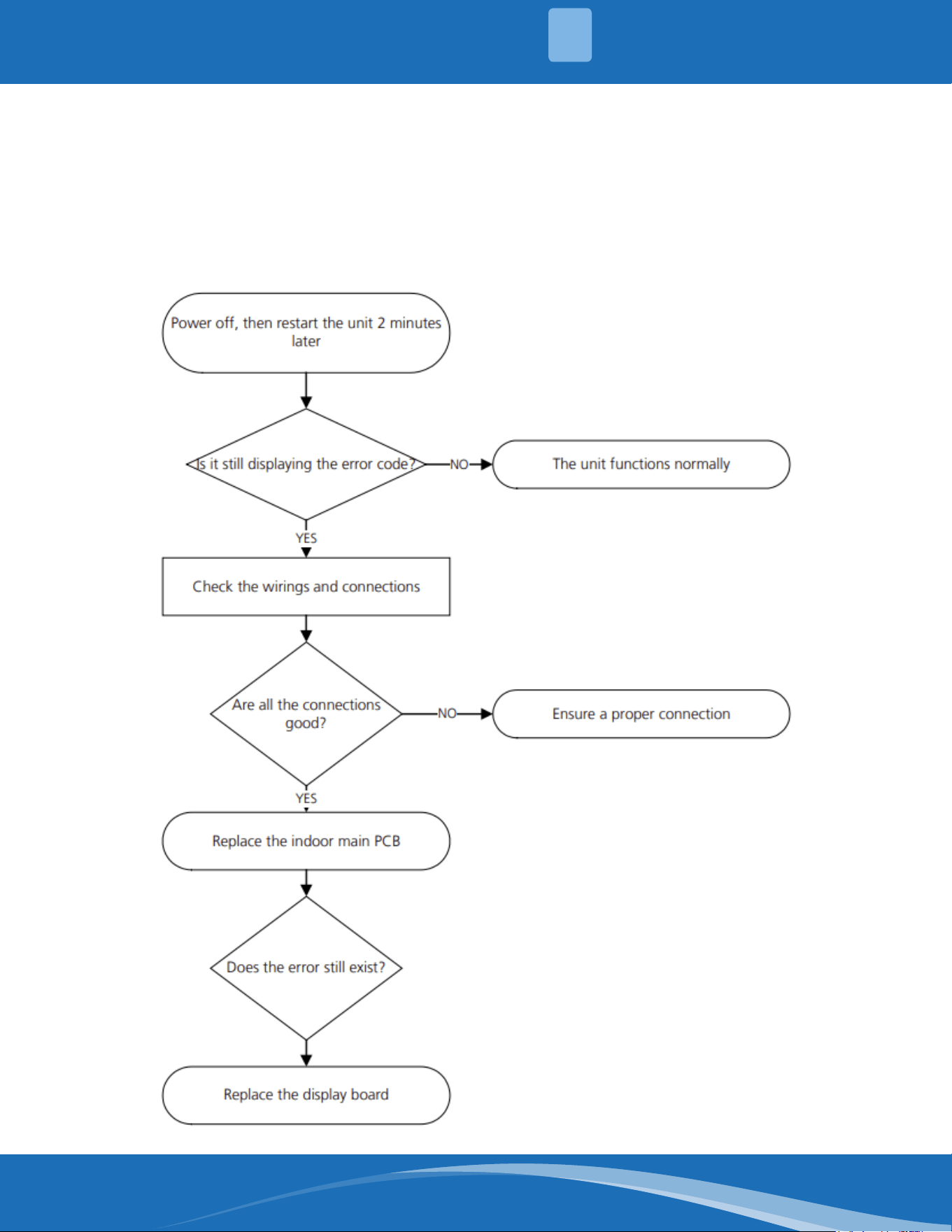
mrcool.com 66
TROUBLESHOOTING
5
EH 0b: IDU main control board and display board communication error diagnosis
and solution.
Description: Indoor PCB does not receive feedback from the display board.
Recommended parts to prepare:
• Communication wire
• Indoor PCB
• Display board
Troubleshooting and repair:
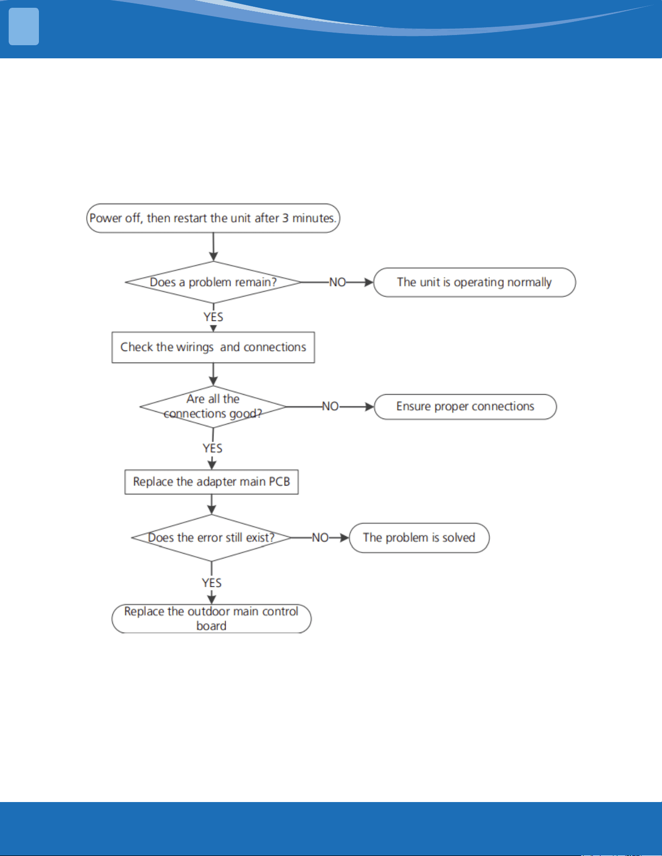
mrcool.com67
TROUBLESHOOTING
5
EL 16: Communication malfunction between adapter board and outdoor main
board diagnosis and solution.
Description: The adapter PCB cannot detect the main control board.
Recommended parts to prepare:
• Connection wires
• Adapter board
• Outdoor main PCB
Troubleshooting and repair:
FL 09: Mismatch between the new and old platforms diagnosis and solution.
Description: Indoor and outdoor units are mismatched, the LED displays this code. Please replace the
matching indoor or outdoor unit.
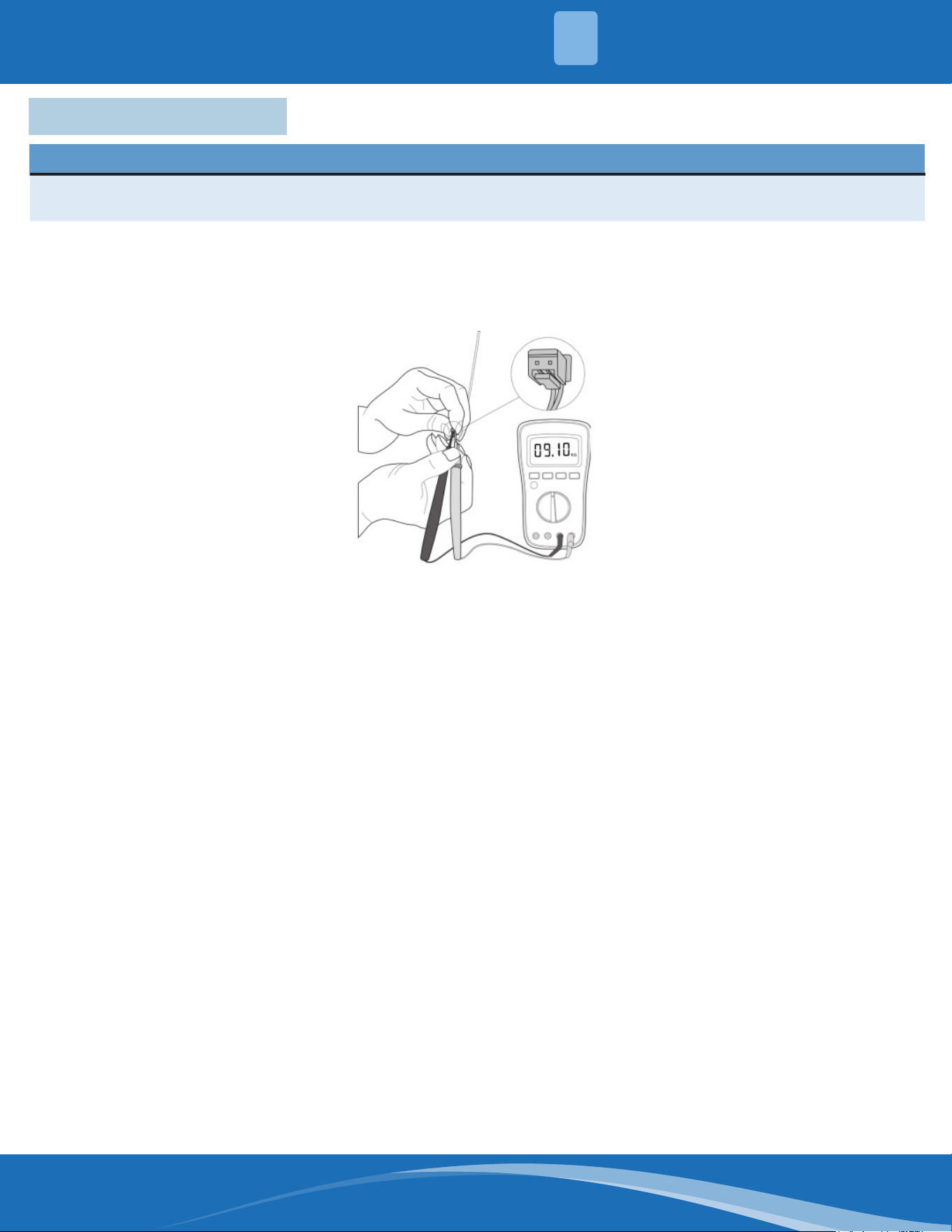
mrcool.com 68
TROUBLESHOOTING
5
5.7 Check Procedures
WARNING
Besuretoturnoallpowersuppliesordisconnectallwirestoavoidelectricshock.Operateonlyafter
thecompressorandcoilhasreturnedtonormaltemperatureincaseofinjury.
1. Disconnect the temperature sensor from the PCB.
2. Measure the resistance value of the sensor using a multi-meter.
3. Check corresponding temperature sensor resistance value table.
Note: The picture and the value are for reference only, actual condition and specic values may vary.
Temperature Sensor Check:
mrcool.com69
°C °F K Ohm °C °F K Ohm °C °F K Ohm °C °F K Ohm
-20 -4 542.7 20 68 68.66 60 140 13.59 100 212 3.702
-19 -2 511.9 21 70 65.62 61 142 13.11 101 214 3.595
-18 0 483 22 72 62.73 62 144 12.65 102 216 3.492
-17 1 455.9 23 73 59.98 63 145 12.21 103 217 3.392
-16 3 430.5 24 75 57.37 64 147 11.79 104 219 3.296
-15 5 406.7 25 77 54.89 65 149 11.38 105 221 3.203
-14 7 384.3 26 79 52.53 66 151 10.99 106 223 3.113
-13 9 363.3 27 81 50.28 67 153 10.61 107 225 3.025
-12 10 343.6 28 82 48.14 68 154 10.25 108 226 2.941
-11 12 325.1 29 84 46.11 69 156 9.902 109 228 2.86
-10 14 307.7 30 86 44.17 70 158 9.569 110 230 2.781
-9 16 291.3 31 88 42.33 71 160 9.248 111 232 2.704
-8 18 275.9 32 90 40.57 72 162 8.94 112 234 2.63
-7 19 261.4 33 91 38.89 73 163 8.643 113 235 2.559
-6 21 247.8 34 93 37.3 74 165 8.358 114 237 2.489
-5 23 234.9 35 95 35.78 75 167 8.084 115 239 2.422
-4 25 222.8 36 97 34.32 76 169 7.82 116 241 2.357
-3 27 211.4 37 99 32.94 77 171 7.566 117 243 2.294
-2 28 200.7 38 100 31.62 78 172 7.321 118 244 2.233
-1 30 190.5 39 102 30.36 79 174 7.086 119 246 2.174
0 32 180.9 40 104 29.15 80 176 6.859 120 248 2.117
1 34 171.9 41 106 28 81 178 6.641 121 250 2.061
2 36 163.3 42 108 26.9 82 180 6.43 122 252 2.007
3 37 155.2 43 109 25.86 83 181 6.228 123 253 1.955
4 39 147.6 44 111 24.85 84 183 6.033 124 255 1.905
5 41 140.4 45 113 23.89 85 185 5.844 125 257 1.856
6 43 133.5 46 115 22.89 86 187 5.663 126 259 1.808
7 45 127.1 47 117 22.1 87 189 5.488 127 261 1.762
8 46 121 48 118 21.26 88 190 5.32 128 262 1.171
9 48 115.2 49 120 20.46 89 192 5.157 129 264 1.674
10 50 109.8 50 122 19.69 90 194 5 130 266 1.632
11 52 104.6 51 124 18.96 91 196 4.849
12 54 99.69 52 126 18.26 92 198 4.703
13 55 95.05 53 127 17.58 93 199 4.562
14 57 90.66 54 129 16.94 94 201 4.426
15 59 86.49 55 131 16.32 95 203 4.294
16 61 82.54 56 133 15.73 96 205 4.167
17 63 78.79 57 135 15.16 97 207 4.045
18 64 75.24 58 136 14.62 98 208 3.927
19 66 71.86 59 138 14.09 99 210 3.812
Temperature Sensor Resistance Value Table (°C-K)
TEMPERATURE SENSOR RESISTANCE TABLE
6
mrcool.com 70
Other Temperature Sensor Resistance Value Table (°C-K)
°C °F K Ohm °C °F K Ohm °C °F K Ohm °C °F K Ohm
-20 -4 115.266 20 68 12.6431 60 140 2.35774 100 212 0.62973
-19 -2 108.146 21 70 12.0561 61 142 2.27249 101 214 0.61148
-18 0 101.517 22 72 11.5 62 144 2.19073 102 216 0.59386
-17 1 96.3423 23 73 10.9731 63 145 2.11241 103 217 0.57683
-16 3 89.5865 24 75 10.4736 64 147 2.03732 104 219 0.56038
-15 5 84.219 25 77 10 65 149 1.96532 105 221 0.54448
-14 7 79.311 26 79 9.55074 66 151 1.89627 106 223 0.52912
-13 9 74.536 27 81 9.12445 67 153 1.89627 107 225 0.51426
-12 10 70.1698 28 82 8.71983 68 154 1.83003 108 226 0.49989
-11 12 66.0898 29 84 8.3356 69 156 1.76647 109 228 0.486
-10 14 62.2756 30 86 7.97078 70 158 1.70547 110 230 0.47256
-9 16 58.7079 31 88 7.62411 71 160 1.64691 111 232 0.45957
-8 18 56.3694 32 90 7.29464 72 162 1.59068 112 234 0.44699
-7 19 52.2438 33 91 6.98142 73 163 1.53668 113 235 0.43482
-6 21 49.3161 34 93 6.68355 74 165 1.48481 114 237 0.42304
-5 23 46.5725 35 95 6.40021 75 167 1.43498 115 239 0.41164
-4 25 44 36 97 6.13059 76 169 1.38703 116 241 0.4006
-3 27 41.5878 37 99 5.87359 77 171 1.34105 117 243 0.38991
-2 28 39.8239 38 100 5.62961 78 172 1.29078 118 244 0.37956
-1 30 37.1988 39 102 5.3689 79 174 1.25423 119 246 0.36954
0 32 35.2024 40 104 5.17519 80 176 1.2133 120 248 0.35982
1 34 33.3269 41 106 4.96392 81 178 1.17393 121 250 0.35042
2 36 31.5635 42 108 4.76253 82 180 1.13604 122 252 0.3413
3 37 29.9058 43 109 4.5705 83 181 1.09958 123 253 0.33246
4 39 28.3459 44 111 4.38736 84 183 1.06448 124 255 0.3239
5 41 26.8778 45 113 4.21263 85 185 1.03069 125 257 0.31559
6 43 25.4954 46 115 4.04589 86 187 0.99815 126 259 0.30754
7 45 24.1932 47 117 3.88673 87 189 0.96681 127 261 0.29974
8 46 22.5662 48 118 3.73476 88 190 0.93662 128 262 0.29216
9 48 21.8094 49 120 3.58962 89 192 0.90753 129 264 0.28482
10 50 20.7184 50 122 3.45097 90 194 0.8795 130 266 0.2777
11 52 19.6891 51 124 3.31847 91 196 0.85248 131 268 0.27078
12 54 18.7177 52 126 3.19183 92 198 0.82643 132 270 0.26408
13 55 17.8005 53 127 3.07075 93 199 0.80132 133 271 0.25757
14 57 16.9341 54 129 2.95896 94 201 0.77709 134 273 0.25125
15 59 16.1156 55 131 2.84421 95 203 0.7537 135 275 0.24512
16 61 15.3418 56 133 2.73823 96 205 0.73119 136 277 0.23916
17 63 14.6181 57 135 2.63682 97 207 0.68844 137 279 0.23338
18 64 13.918 58 136 2.53973 98 208 0.66818 138 280 0.22776
19 66 13.2631 59 138 2.4467 99 210 0.64862 139 282 0.22231
6
TEMPERATURE SENSOR RESISTANCE TABLE
mrcool.com71
Pressure Temperature Pressure Temperature
Kpa Bar PSI °C °F Kpa Bar PSI °C °F
58.196 0.58 8.44 -60 -76 935.23 9.35 135.64 8 46.4
61.517 0.62 8.92 -59 -74.2 963.75 9.64 139.78 9 48.2
64.988 0.65 9.43 -58 -72.4 992.93 9.93 14401 10 50
68.615 0.69 9.95 -57 -70.6 1022.8 10.23 148.34 11 51.8
72.402 .072 10.50 -56 -68.8 1053.3 10.53 152.76 12 53.6
76.354 0.76 11.07 -55 -67 1084.5 10.85 157.29 13 55.4
80.478 0.80 11.67 -54 -65.2 1116.4 11.16 161.91 14 57.2
84.776 0.85 12.30 -53 -63.4 1149 11.49 166.64 15 59
89.256 0.89 12.95 -52 -61.6 1182.3 11.82 171.47 16 60.8
93.923 0.94 13.62 -51 -59.8 1216.3 12.16 176.40 17 62.6
98.781 0.99 14.33 -50 -58 1251.1 12.51 181.45 18 64.4
103.84 1.04 15.06 -49 -56.2 1286.6 12.87 186.60 19 66.2
109.1 1.09 15.82 -48 -54.4 1322.8 13.23 191.85 20 68
114.56 1.15 16.61 -47 -52.6 1359.9 13.60 197.23 21 69.8
120.25 1.20 17.44 -46 -50.8 1397.7 13.98 202.71 22 71.6
126.15 1.26 18.30 -45 -49 1436.3 14.36 208.31 23 73.4
132.28 1.32 19.18 -44 -47.2 1475.7 14.76 214.02 24 75.2
138.64 1.39 20.11 -43 -45.4 1515.9 15.16 219.85 25 77
145.24 1.45 21.06 -42 -43.6 1557 15.57 225.82 26 78.8
152.09 1.52 22.06 -41 -41.8 1598.9 15.99 231.89 27 80.6
159.18 1.59 23.09 -40 -40 1641.6 16.42 238.09 28 82.4
166.54 1.67 24.15 -39 -38.2 1685.2 16.85 244.41 29 84.2
174.15 1.74 25.26 -38 -36.4 1729.7 17.30 250.86 30 86
182.04 1.82 26.40 -37 -34.6 1775 17.75 257.43 31 87.8
190.2 1.90 27.59 -36 -32.8 1821.3 18.21 264.15 32 89.6
198.65 1.99 28.81 -35 -31 1868.4 18.68 270.98 33 91.4
207.39 2.07 30.08 -34 -29.2 1916.5 19.17 277.95 34 93.2
216.42 2.16 31.39 -33 -27.4 1965.6 19.66 285.08 35 95
225.76 2.26 32.74 -32 -25.6 2015.5 20.16 292.31 36 96.8
235.41 2.35 34.14 -31 -23.8 2066.5 20.67 299.71 37 98.6
245.37 2.45 35.59 -30 -22 2118.4 21.18 307.24 38 100.4
255.67 2.56 37.08 -29 -20.2 2171.3 21.71 314.19 39 102.2
266.29 2.66 38.62 -28 -18.4 2225.2 22.25 322.73 40 104
277.25 2.77 40.21 -27 -16.6 2280.2 22.80 330.70 41 105.8
288.56 2.89 41.85 -26 -14.8 2336.1 23.36 38.81 42 107.6
300.22 3.00 43.54 -25 -13 2393.2 23.93 347.09 43 109.4
312.24 3.12 45.28 -24 -11.2 2451.3 24.51 355.52 44 111.2
324.63 3.25 47.08 -23 -9.4 2510.4 25.10 364.09 45 113
337.39 3.37 48.93 -22 -7.6 2570.7 25.71 372.84 46 114.8
350.54 3.51 50.84 -21 -5.8 2632.1 26.32 381.74 47 116.6
364.08 3.64 52.80 -20 -4 2694.7 26.95 390.82 48 118.4
378.02 3.78 54.83 -19 -2.2 2758.33 27.58 400.04 49 120.2
392.37 3.92 56.91 -18 -0.4 2823.2 28.23 409.46 50 122
407.13 4.07 59.05 -17 1.4 2889.3 28.89 419.04 51 123.8
System Pressure Table-R454B
SYSTEM PRESSURE TABLE
7
mrcool.com 72
Pressure Temperature Pressure Temperature
Kpa Bar PSI °C °F Kpa Bar PSI °C °F
422.31 4.22 61.25 -16 3.2 2956.5 29.57 428.79 52 125.6
437.92 4.38 63.5 -15 5 3025 30.25 438.72 53 127.4
453.98 4.54 65.84 -14 6.8 3094.7 30.95 448.83 54 129.2
470.47 4.70 68.23 -13 8.6 3165.7 31.66 459.13 55 131
487.43 4.87 70.69 -12 10.4 3238.1 32.38 469.63 56 132.8
504.84 5.05 73.22 -11 12.2 3311.7 33.12 480.30 57 134.6
522.73 5.23 75.81 -10 14 3386.7 33.87 491.18 58 136.4
541.1 5.41 78.48 -9 15.8 3463 34.63 502.25 59 138.2
559.95 5.60 81.21 -8 17.6 3540.7 35.41 513.52 60 140
579.31 5.79 84.02 -7 19.4 3619.9 36.20 525.00 61 141.8
599.16 5.99 86.90 -6 21.2 3700.5 37.01 536.69 62 143.6
619.54 6.20 89.85 -5 23 3782.7 37.83 548.61 63 145.4
640.43 6.40 92.88 -4 24.8 3866.3 38.66 560.74 64 147.2
661.86 6.62 95.99 -3 26.6 3951.5 39.52 573.10 65 149
683.82 6.84 99.18 -2 28.4 4038.3 40.38 585.69 66 450.28
706.34 7.06 102.44 -1 30.2 4126.8 41.27 598.52 67 152.6
729.41 7.29 105.79 0 32 4217 42.17 611.60 68 154.4
753.06 7.53 109.22 1 33.8 4309 43.09 624.95 69 156.2
777.28 7.77 112.73 2 35.6 4402.9 44.03 638.56 70 158
802.08 8.02 116.33 3 37.4 4498.7 44.99 652.46 71 159.8
827.47 8.27 120.01 4 39.2 4596.5 45.97 666.64 72 161.6
853.49 8.53 123.78 5 41 4696.5 46.97 681.15 73 163.4
880.11 8.80 127.64 6 42.8 4798.9 47.99 696.00 74 165.5
907.35 9.07 131.60 7 44.6 4904.1 49.04 711.25 75 167
System Pressure Table-R454B Cont.
7
SYSTEM PRESSURE TABLE

MRCOOL®
A-Coil
Service Manual
The design and specications of this product and/or manual are subject to change without prior notice.
Consult with the sales agency or manufacturer for details.