ALL TECHNICAL AND WARRANTY QUESTIONS: SHOULD BE DIRECTED TO THE LOCAL DEALER FROM WHOM THE
WATER HEATER WAS PURCHASED. IF YOU ARE UNSUCCESSFUL, PLEASE WRITE TO THE COMPANY LISTED ON THE
RATING PLATE ON THE WATER HEATER.
KEEP THIS MANUAL IN THE POCKET ON HEATER FOR FUTURE REFERENCE WHENEVER MAINTENANCE
ADJUSTMENT OR SERVICE IS REQUIRED.
100341945_2000542152E
PRINTED 0321
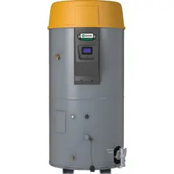
Instruction Manual
RESIDENTIAL GAS WATER HEATERS
POWER VENTED GAS MODELS W/HOT SURFACE IGNITION
NOT FOR USE IN MANUFACTURED (MOBILE) HOMES
LOW LEAD
CONTENT
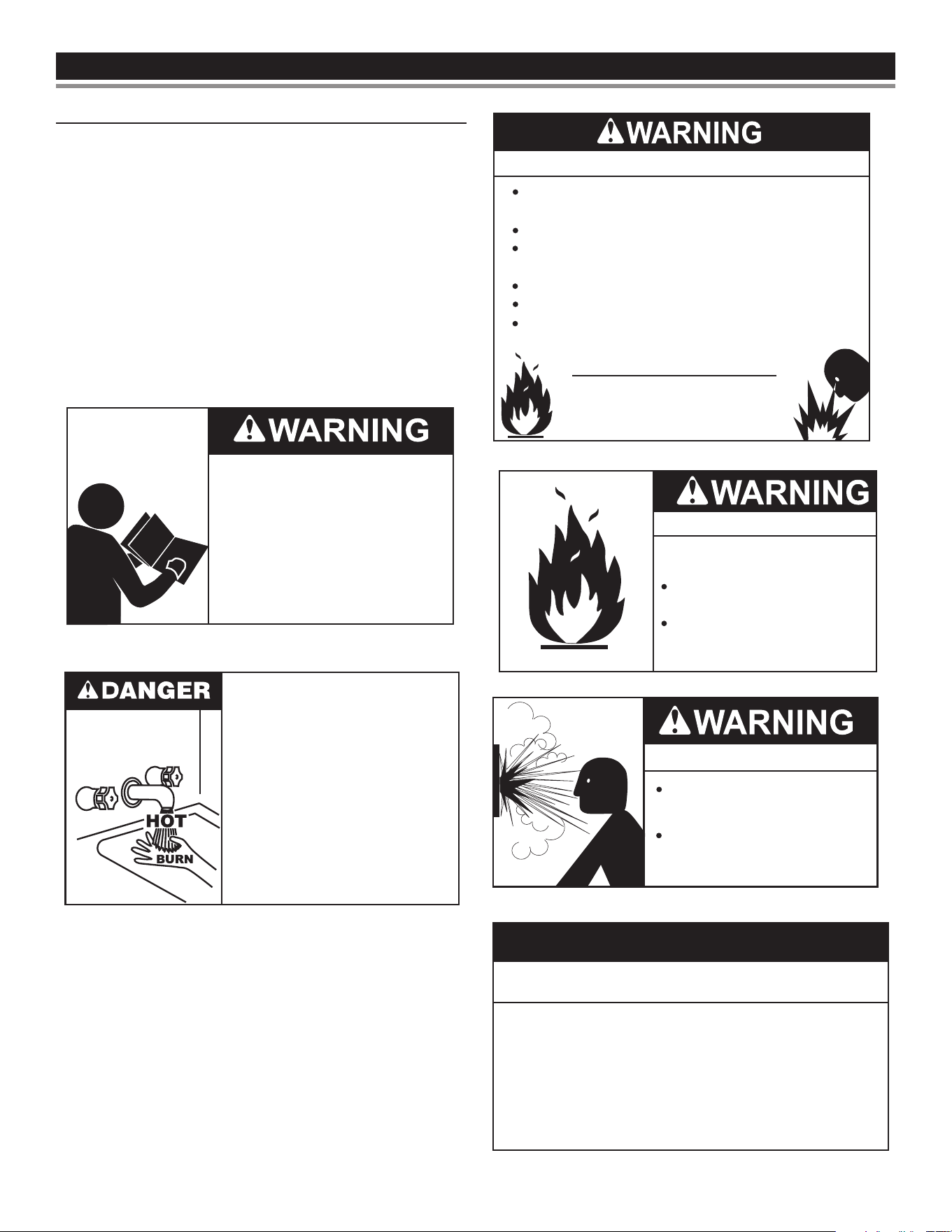
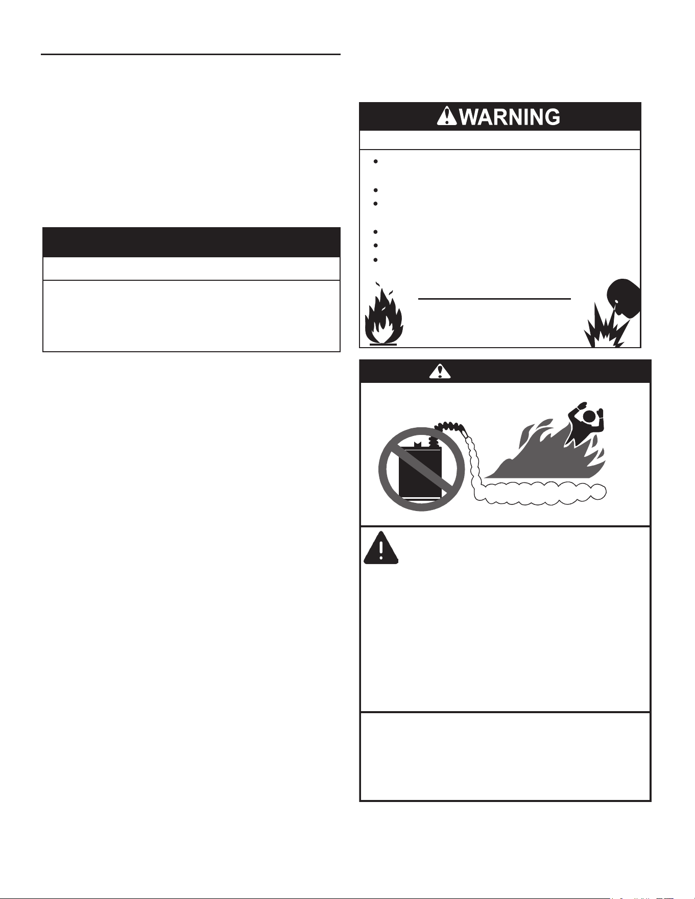
WARNING: If the information in these
instructions is not followed exactly, a fire
or explosion may result causing property
damage, personal injury or death.
Do not store or use gasoline or other
flammable vapors and liquids in the
vicinity of this or any other appliance.
WHAT TO DO IF YOU SMELL GAS:
Do not try to light any appliance.
Do not touch any electrical switch; do
not use any phone in your building.
Immediately call your gas supplier
from a neighbor’s phone. Follow the
gas supplier’s instructions.
If you cannot reach your gas supplier,
call the fire department.
Installation and service must be
performed by a qualified installer,
service agency or the gas supplier.
•
•
•
•
Thank You for purchasing this Thermal Expansion Tank. Properly
installed and maintained, it should give you years of trouble free
service.
Read and understand this instruction
manual and the safety messages
herein before installing, operating or
servicing this water heater.
Failure to follow these instructions and
safety messages could result in death
or serious injury.
This manual must remain with the
water heater.
For Your Safety
AN ODORANT IS ADDED TO THE GAS USED
BY THIS WATER HEATER.

CONTENTSCONTENTS
SAFE INSTALLATION, USE, AND SERVICE .......................3
Important Denitions ............................................................3
APPROVALS ...........................................................................3
GENERAL SAFETY INFORMATION .....................................4
Limiting The Risk Of Scalding ..............................................4
INTRODUCTION ....................................................................6
Qualied Installer or Service Agency ....................................6
Preparing for the Installation ................................................6
RECOMMENDED ACCESSORIES: .....................................6
FEATURES AND COMPONENTS .........................................7
Replacement Parts and Deliming Products ..........................7
INSTALLATION CONSIDERATIONS ....................................9
Rough-In Dimensions ...........................................................9
Locating the New Water Heater .........................................10
Insulation Blankets .............................................................11
INSTALLATION REQUIREMENTS .....................................13
Water Piping .......................................................................13
Thermostatic Point-of-Use Mixing Valves ...........................13
Space Heating and Potable Water System ........................13
Closed Water Systems .......................................................14
Thermal Expansion ............................................................14
Installing T&P Valve and Pipe Insulation (if supplied) ........14
Temperature-Pressure Relief Valve ....................................15
Chemical Vapor Corrosion..................................................16
Air Requirements ................................................................16
Combustion Air and Ventilation ..........................................16
Unconned Space ..............................................................16
Conned Space ..................................................................16
Fresh Air Openings For Conned Spaces ..........................17
Air From Other Indoor Spaces ...........................................18
INSTALLATION REQUIREMENTS FOR THE
COMMONWEALTH OF MASSACHUSETTS ......................19
Commonwealth of Massachusetts .....................................19
VENTING INSTALLATION ...................................................20
Approved vent pipe materials: ............................................20
Planning The Vent System .................................................20
Vent Pipe Termination ........................................................20
Blower Assembly Installation ..............................................21
Vent Sound Silencer ...........................................................21
Installation of Vent System .................................................21
Horizontal Vent Termination Installation .............................22
Vertical Vent Termination Installation ..................................22
Vent Pipe Preparation ........................................................23
Vent Pipe Assembly ............................................................25
Polypropylene Installations .................................................26
Termination Clearances Other than Sidewall Direct Vent ...27
WATER HEATER INSTALLATION .......................................28
Condensate Drain Installation ............................................28
Gas Piping ..........................................................................28
Sediment Traps ..................................................................29
Filling the Water Heater ......................................................30
TEMPERATURE REGULATION ..........................................31
Hot Water Can Scald ..........................................................31
Changing the Temperature Setting .....................................31
High Water Temperature Shut O System .........................32
START UP .............................................................................33
Start Up Conditions ............................................................33
Operational Conditions .......................................................33
High Water Temperature Shuto System ...........................33
High Altitude Installation .....................................................33
Lighting And Operation Label .............................................34
TROUBLESHOOTING GUIDELINES .................................35
Leakage Checkpoints .........................................................38
PERIODIC MAINTENANCE.................................................39
Draining and Flushing ........................................................39
Sediment and Lime Scale Removal ...................................39
Burner Operation and Inspection .......................................40
Burner Cleaning .................................................................40
Anode Rod Inspection ........................................................40
Temperature-Pressure Relief Valve Test ............................40
Vent System Maintenance ..................................................41
Housekeeping ....................................................................41
Service ...............................................................................41
REPAIR PARTS LIST ...........................................................43
WIRING DIAGRAM ...............................................................44
2
SAFE INSTALLATION, USE, AND SERVICESAFE INSTALLATION, USE, AND SERVICE
The proper installation, use and servicing of this water heater is extremely important to your safety and the safety of others.
Many safety-related messages and instructions have been provided in this manual and on your own water heater to warn you and others of
a potential injury hazard. Read and obey all safety messages and instructions throughout this manual. It is very important that the meaning
of each safety message is understood by you and others who install, use, or service this water heater.
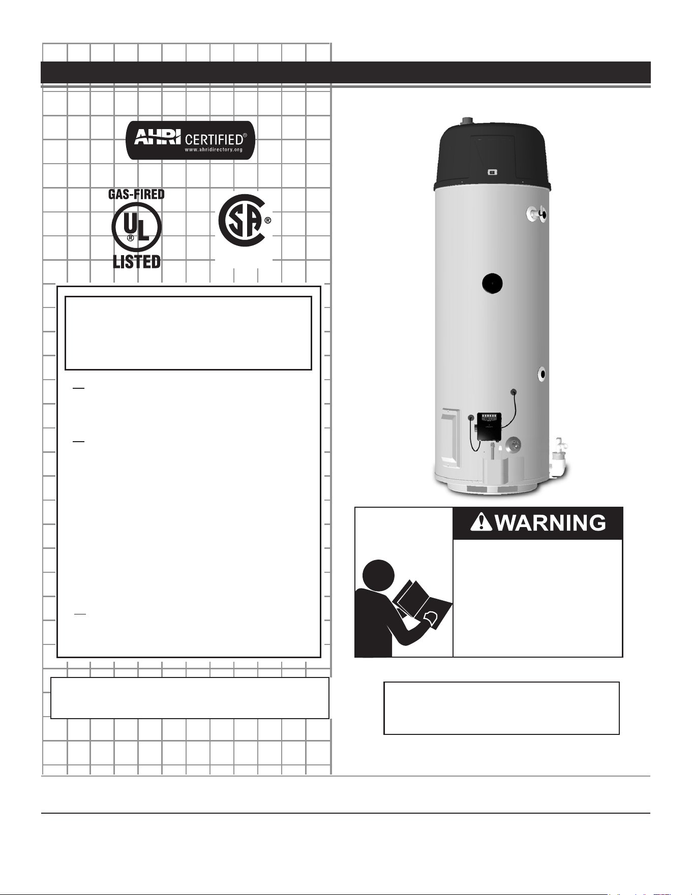
DANGER
WARNING
CAUTION
CAUTION
DANGER indicates an imminently
hazardous situation which, if not avoided,
will result in injury or death.
This is the safety alert symbol. It is used to alert you to
potential personal injury hazards. Obey all safety
messages that follow this symbol to avoid possible
injury or death. Keep this manual near the water heater.
WARNING indicates a potentially hazardous
situation which, if not avoided, could result
in injury or death.
CAUTION indicates a potentially hazardous
situation which, if not avoided, could result in
minor or moderate injury.
CAUTION used without the safety alert
symbol indicates a potentially hazardous
situation which, if not avoided, could result in
property damage.
All safety messages will generally tell you about the type of hazard, what can happen if you do not follow the safety message, and how
to avoid the risk of injury.
IMPORTANT DEFINITIONS
Gas Supplier: The Natural Gas or Propane Utility or service who supplies gas for utilization by the gas burning appliances within this
application. The gas supplier typically has responsibility for the inspection and code approval of gas piping up to and including the Natural
Gas meter or Propane storage tank of a building. Many gas suppliers also oer service and inspection of appliances within the building.
APPROVALSAPPROVALS
LOW LEAD
CONTENT
3
GENERAL SAFETY INFORMATIONGENERAL SAFETY INFORMATION
LIMITING THE RISK OF SCALDING
To reduce the risk of unusually hot water reaching the xtures in
the house, install thermostatic mixing valves at each point of use.
According to a national standard (ASSE 1070) and many local
plumbing codes, the water heater’s gas control valve should not be
used as the sole means to regulate water temperature and avoid
scalds.
A properly adjusted thermostatic mixing valve at each point of use
allows you to set the tank temperature to a higher setting without
increasing risk of scalds. A higher temperature setting allows the
tank to provide much more hot water and can help provide proper
water temperatures for appliances such as dishwashers and washing
machines.
Higher tank temperatures (140°F) also kill bacteria that cause a
condition known as “smelly water” and can reduce the levels of
bacteria that cause water-borne diseases.
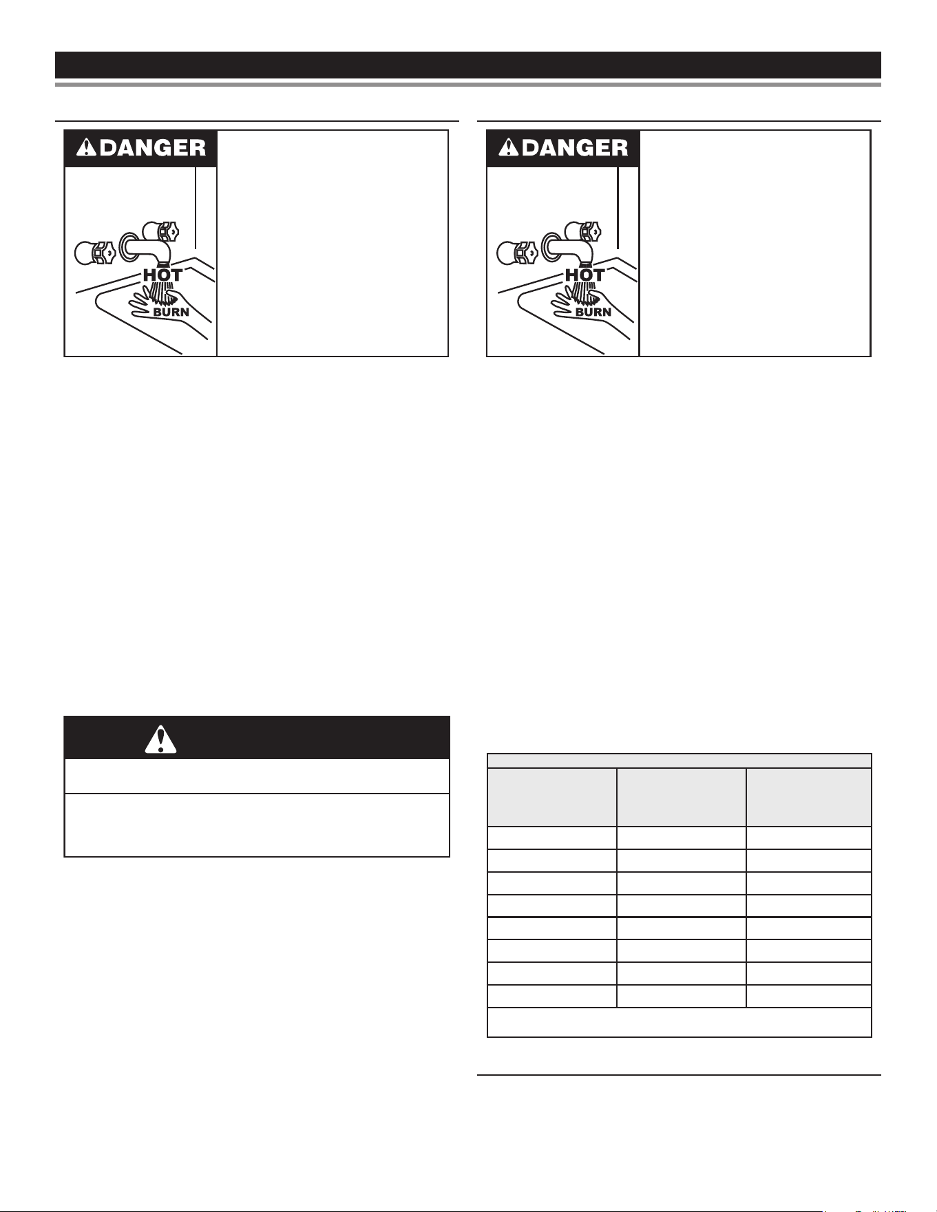
Read and understand this instruction
manual and the safety messages
herein before installing, operating or
servicing this water heater.
Failure to follow these instructions and
safety messages could result in death
or serious injury.
This manual must remain with the
water heater.
Water temperature over 125°F (52°C)
can cause severe burns instantly
resulting in severe injury or death.
Children, the elderly and the physically
or mentally disabled are at highest risk
for scald injury.
Feel water before bathing or showering.
Temperature limiting devices such as
point-of-use mixing valves must be
installed when required by codes and to
ensure safe temperatures at fixtures.
Fire or Explosion Hazard
Read instruction manual before
installing, using or servicing
water heater.
Avoid all ignition sources if you smell gas.
Do not store or use gasoline or other flammable vapors and
liquids in the vicinity of this or any other appliance.
Use only the gas shown on the water heater rating label.
Keep ignition sources away from faucets after extended
periods of non-use.
Maintain required clearances to combustibles.
Do not expose water heater controls to excessive gas
pressure.
Fire Hazard
Do not install water heater on
carpeted floor.
Do not operate water heater if
exposed to flooding or water
damage.
For continued protection against
risk of fire:
Explosion Hazard
Overheated water can cause the
water tank to explode.
Properly-sized temperature and
pressure relief valves must be
installed int the opening provided.
Improper installation, use and service may result
in property damage.
•
Do not operate water heater if any part has been exposed
to flooding or water damage.
•
Inspect anode rods regularly, replace if damaged.
•
Install in location with drainage.
•
Fill tank with water before operation.
•
Properly sized thermal expansion tanks are required on all
closed water systems.
Refer to this manual for installation and service.
CAUTION
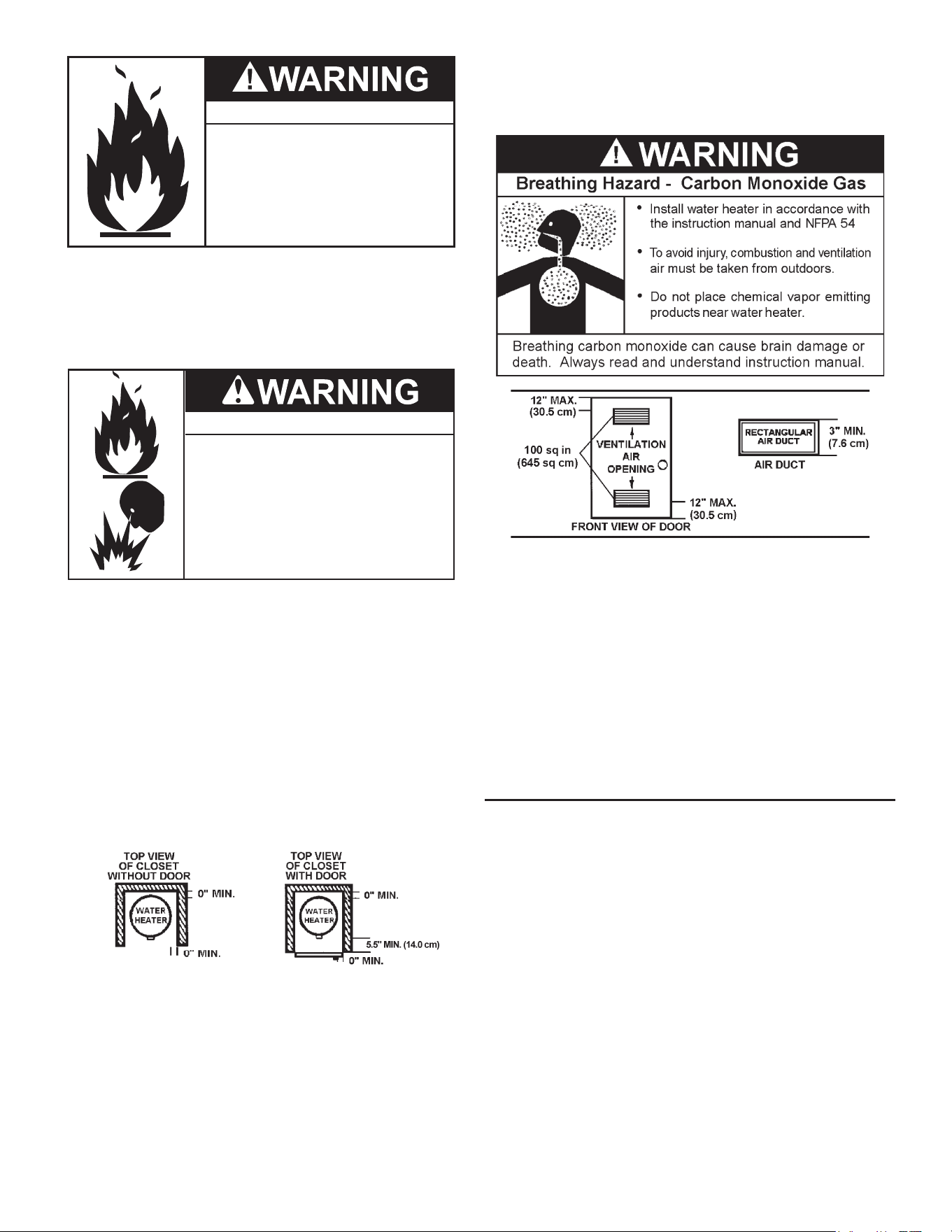
4
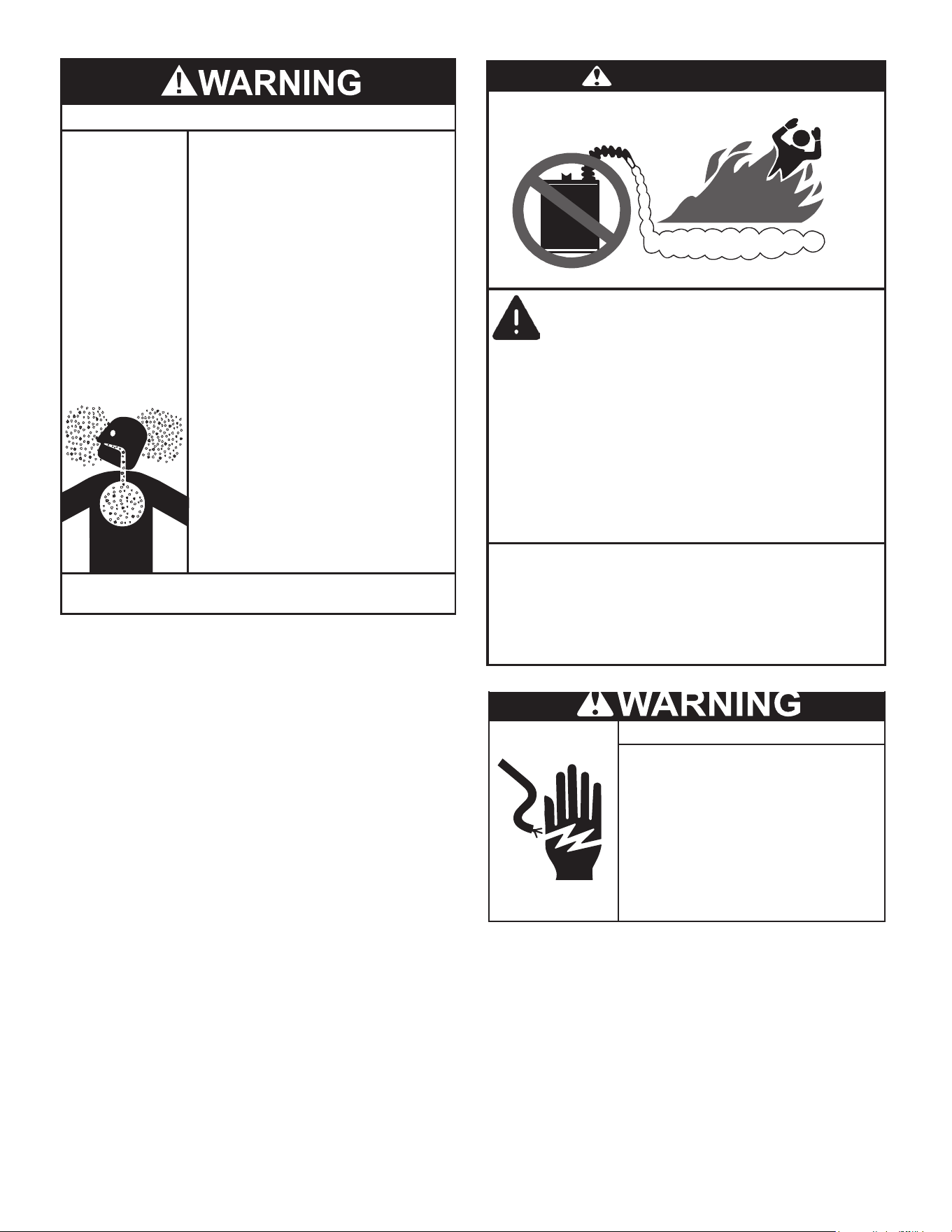
Breathing Hazard - Carbon Monoxide Gas
•
Install vent system in accordance with codes.
•
Do not operate water heater if any part has been
exposed to flooding or water damage.
•
High altitude models should be installed at
elevations
above
5,300
feet
(
1,615 m
).
For operation above
10,100
feet (3,079 m), a high altitude orifice must be installed.
•
Do not operate if soot buildup is present.
•
Do NOT elevate any portion of the field supplied
drain line beyond the 1/2” adaptor above the
adaptor. This must be true for the entire length
of the drain line including the exit into an
appropriate drain.
•
Condensate lines must be free and clear of debris
and must not allow back flow through the hose.
The condensate lines must be able to flow freely
to an appropriate drain.
•
Do not obstruct water heater air intake with
insulating jacket.
•
Do not place chemical vapor emitting products
near water heater.
•
Do not allow condensate lines to become
crimped closed.
•
Analyze the entire vent system to make sure
that condensate will not become trapped in a
section of vent pipe and therefore reduce the open
cross sectional area of the vent.
•
Gas and carbon monoxide detectors are available.
•
No vent damper installation is compatible with
this power vented water heater.
Breathing carbon monoxide can cause brain damage or
death. Always read and understand instruction manual.
Flammable Vapors
FLAMMABLES
DANGER
Vapors from flamable
liquids may explode
and catch fire causing
death or sever burns.
Water heater has a main
burner and ignition device.
The ignition device:
1. Can come on at any time.
2. Will ignight flammable
vapors.
Do not use or store flammable
products, such as gasoline,
solvents, or adhesives in the
same room or area near the
water heater.
Keep flamable products:
1. Fare away from heater.
2. In approved containers.
3. Tightly closed and
4. Out of children’s reach
Vapors:
1. Cannot be seen.
2. Are Heavier than air.
3. Go a long way on the floor.
4. Can be carried from other
rooms to the ignition
device by air currents.
Installation:
Do not install the water heater where flamable products will be
stored or used unless the main burner and hot surface igniter
are at least 18” (457 cm) above the floor. This will reduce, but
not eliminate the risk of vapors being ignited by the main
burner or hot surface igniter.
● Before servicing the water heater, make
sure the blower assembly is unplugged or
the electrical supply to the water heater is
turned OFF.
Electrical Shock Hazard
● Label all wires prior to disconnection when
servicing controls. Wiring errors can cause
improper and dangerous operation. Verify
proper operation after servicing.
● Failure to follow these instructions can
result in personal injury or death.
5

INTRODUCTIONINTRODUCTION
Thank You for purchasing this water heater. Properly installed and
maintained, it should give you years of trouble free service.
Abbreviations Found In This Instruction Manual:
• CSA - Canadian Standards Association
• ANSI - American National Standards Institute
• NFPA - National Fire Protection Association
• ASME - American Society of Mechanical Engineers
• AHRI - Air Conditioning, Heating and Refrigeration Institute
• UL - Underwriters Laboratories Inc.
This gas-red water heater is design certied by Underwriters
Laboratories Inc. under
American National Standard/CSA Standard for Gas
Water Heaters ANSI Z21.10.3 • CSA 4.3 (current edition)
.
QUALIFIED INSTALLER OR SERVICE AGENCY
Installation and service of this water heater requires ability equivalent
to that of a Qualied Agency (as dened by ANSI below) in the eld
involved. Installation skills such as plumbing, air supply, venting,
gas supply and electrical supply are required in addition to electrical
testing skills when performing service.
ANSI Z223.1 2006 Sec. 3.3.83: “Qualied Agency” - “Any individual,
rm, corporation or company that either in person or through a
representative is engaged in and is responsible for (a) the installation,
testing or replacement of gas piping or (b) the connection, installation,
testing, repair or servicing of appliances and equipment; that is
experienced in such work; that is familiar with all precautions
required; and that has complied with all the requirements of the
authority having jurisdiction.”
If you are not qualied (as dened by ANSI above) and licensed or
certied as required by authority having jurisdiction to perform a given
task do not attempt to perform any of the procedures described in this
manual. If you do not understand the instructions given in this manual
do not attempt to perform any procedures outlined in this manual.
PREPARING FOR THE INSTALLATION
1. Read “General Safety Information” section, page 3 and 4 of
this manual rst and then entire manual carefully. If you don’t
follow safety rules, the water heater will not operate properly.
It could cause DEATH, SERIOUS BODILY INJURY AND/OR
PROPERTY DAMAGE.
This manual contains instructions for installation, operation,
and maintenance of the gas-red water heater. It also contains
warnings throughout the manual that you must read and be
aware of. All warnings and all instructions are essential to
proper operation of the water heater and your safety. Since we
cannot put everything on the rst few pages, READ ENTIRE
MANUAL BEFORE ATTEMPTING TO INSTALL OR OPERATE
THE WATER HEATER.
2. The installation must conform with these instructions and local
code authority having jurisdiction. In absence of local codes,
installation must comply with current editions of the
National Fuel
Gas Code, ANSI Z223.1/NFPA 54
and
National Electrical Code
,
NFPA 70
. All
documents are available from Canadian Standards Association,
8501 East Pleasant Valley Road, Cleveland, OH 44131. NFPA
documents are also available from National Fire Protection
Association, 1 Batterymarch Park, Quincy, MA 02269.
3. The water heater when installed must be grounded in accordance
with the local codes, or in the absence of local codes: the
National
Electrical Code (NFPA 70)
.
4. If after reading this manual you have any questions or do not
understand any portion of the instructions, call the local gas utility
or the manufacturer whose name appears on the rating plate.
5. Carefully plan the place where you are going to put the water
heater. Correct combustion, vent action, and vent pipe installation
are very important in preventing death from possible carbon
monoxide poisoning and res, see
Figure 1
(page 7) and
Figure
2
(page 8).
Examine the location to ensure the water heater complies with
Locating the New Water Heater
(page 10).
6. For California installation this water heater must be braced,
anchored, or strapped to avoid falling or moving during an
earthquake. See instructions for correct installation procedures.
Instructions may be obtained from California Oce of the State
Architect, 400 P Street, Sacramento, CA 95814.
7. Massachusetts Code requires this water heater to be installed
in accordance with
Massachusetts 248-CMR 2.00: State Plumbing Code
and 248-CMR 5.00
.
8. Complies with
SCAQMD rule #1146
and districts having equivalent
NOx requirements.
RECOMMENDED ACCESSORIES:
• A metal drain pan.
• Automatic water leak detection and shut-o device.
• Pressure Reducing Valve.
• Thermal Expansion Tank.
• Thermostatic mixing valves at each point of use.
• Fuel gas and carbon monoxide detector.
6
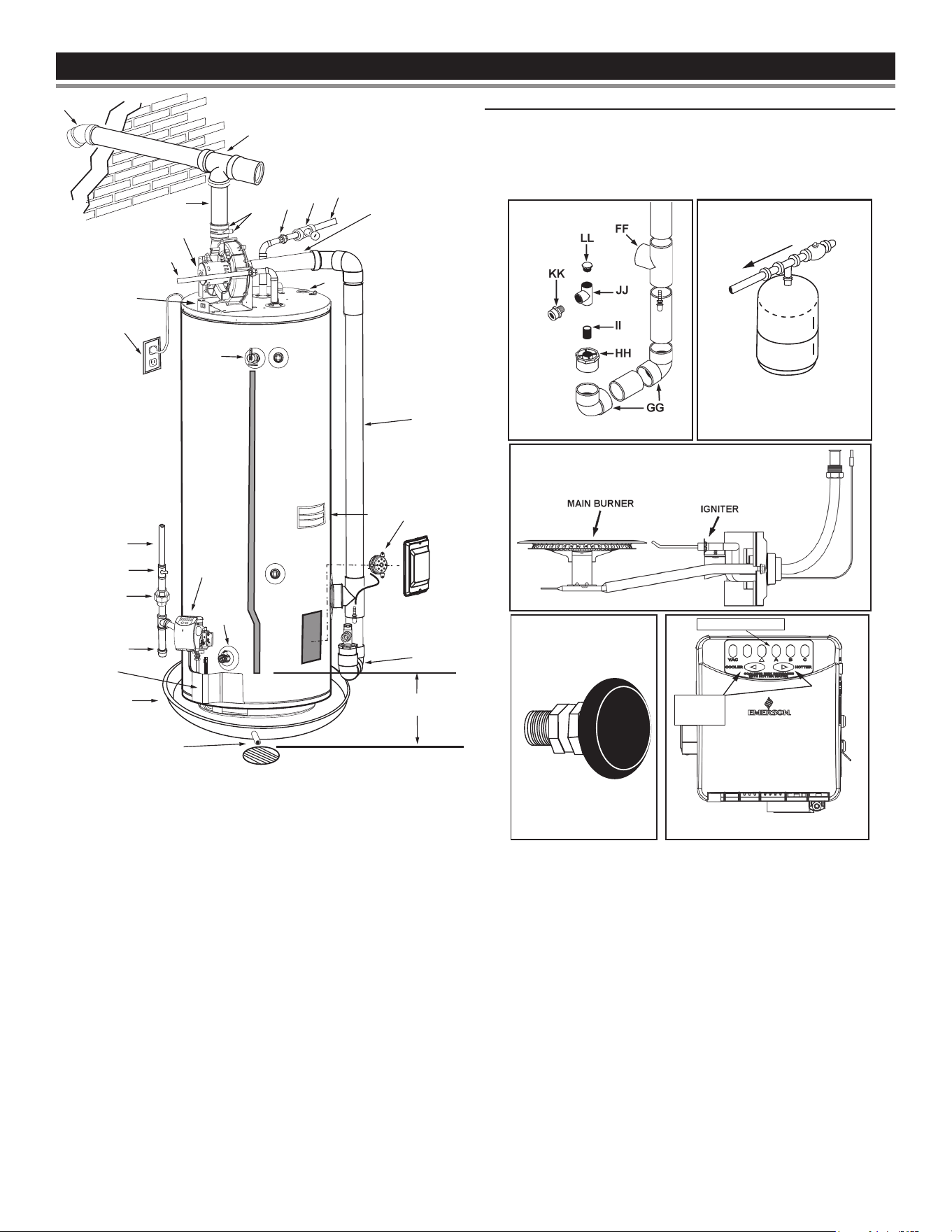
FEATURES AND COMPONENTSFEATURES AND COMPONENTS
EMERSON
EE
L
N
M
S
RR
A
CC
C
D
T
K
W
Q
TO A SUITABLE DRAIN
V
AA
P
B
TT
F
G
H
J
MM
NN
OO
6” (15 cm)
MAXIMUM AIR GAP
REPLACEMENT PARTS AND DELIMING PRODUCTS
Replacement parts and recommended delimer may be ordered
through authorized servicers or distributors. When ordering parts,
provide complete model and serial numbers (see rating plate),
quantity and name of part desired. Standard hardware items may
be purchased locally.
CONDENSATE ASSEMBLY
INSTALL THERMAL EXPANSION
TANK IF WATER HEATER IS
INSTALLED IN A CLOSED
WATER SYSTEM
(U) NATURAL GAS MAIN BURNER WITH IGNITER ASSEMBLY
Vacuum Relief
Valve
Temperature Indicators
Temperature
Adjustment
Buttons
Figure 1. Features and Components - Right Side
* CAUTION HARNESS HAS 120 VAC. IN OPERATION.
** See
Venting Installation
(page 20) and
Condensate Drain Installation
(page 28)
for more information.
*** The side recirculation loop connections may not be used as the primary water inlet and outlet connections. For your convenience, plugs are installed in these
fittings at the factory. Remove these plugs if needed for your specific installation. Otherwise (as with all connections) check for leaks while filling the tank with
water and after completing the installation.
A Vent Pipe Q Rating Plate GG Elbow
B Anode R Insulation HH Bushing
C Hot Water Outlet S Vent Terminal II Nipple
D Outlet (120 VAC) T Drain Valve JJ Condensate Tee
F Gas Supply U Igniter And Main Burner KK Adapter
G Main Manual Gas Shut O Valve V Drain Pan LL Plug
H Ground Joint Union X Temperature Probe Harness MM Vent Pipe Assembly #1
J Sediment Trap Y Control Harness* NN Vent Pipe Assembly #2
K Outer Door Z Temperature Probe OO Vent Pipe Assembly #3
L Union AA Motor & Blower PP Side Recirculation Loop Inlet***
M Inlet Water Shut O Valve CC Condensate Fitting (4 Places Shown)** QQ Side Recirculation Loop Outlet*** (not shown)
N Cold Water Inlet DD Plastic Top RR Vent Sound Silencer (Optional)
O Inlet Dip Tube EE On/O Switch SS Access Door
P Temperature & Pressure Relief Valve FF Exhaust Tee TT Blocked Condensate Air Switch
7
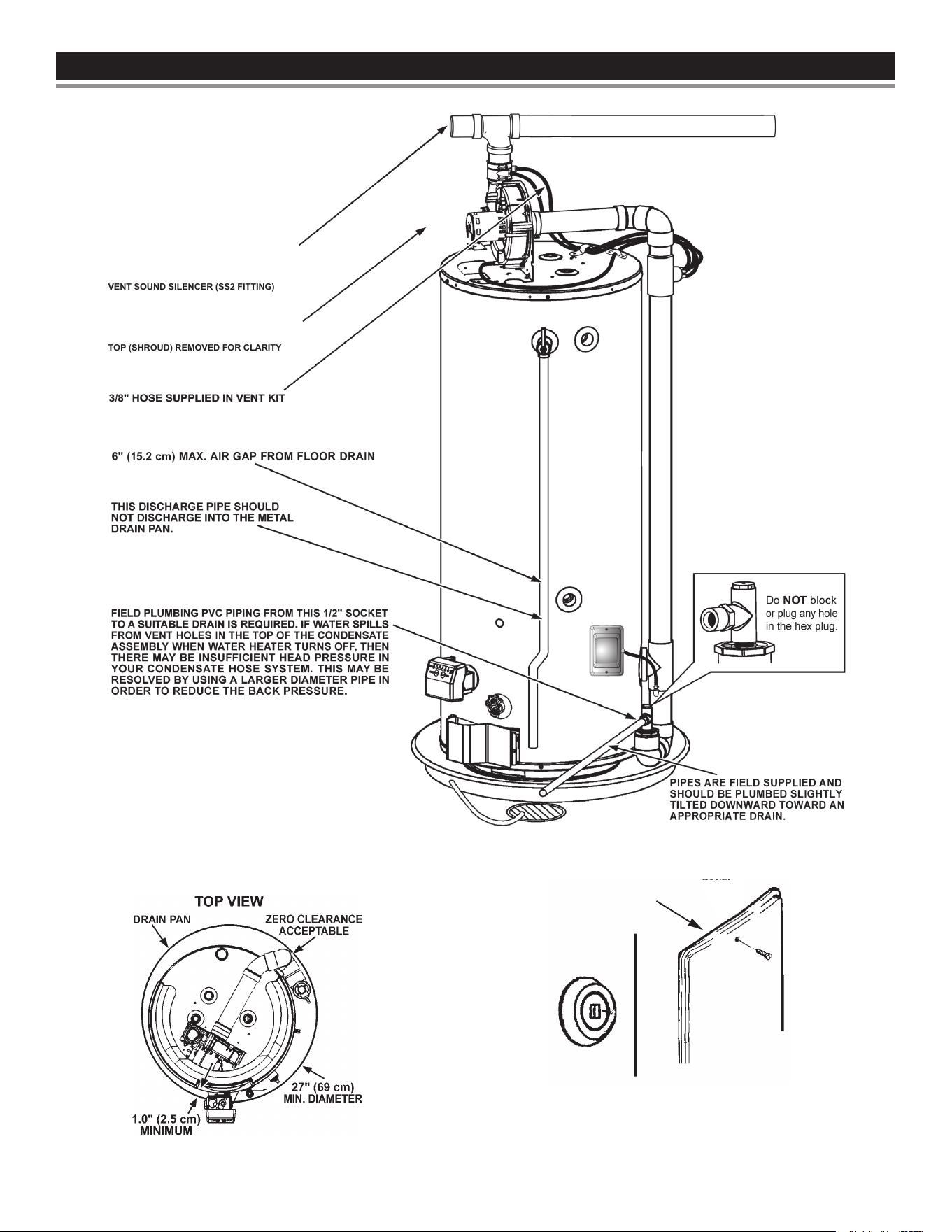
FEATURES AND COMPONENTSFEATURES AND COMPONENTS
TOP (SHROUD) REMOVED FOR CLARITY
VENT SOUND SILENCER (SS2 FITTING)
Figure 2. Features and Components - Left Side
Figure 3. Features and Components - Top
Caution: This access panel covers a 2” NPT plug that
was required during the manufacturing of this water
heater. This 2” NPT flange is not a cleanout fitting,
removing the 2” NPT plug and using this fitting as a
cleanout could void your warranty.
Access
Panel
Figure 4. Manufacturing Access Pannel
8
INSTALLATION CONSIDERATIONSINSTALLATION CONSIDERATIONS
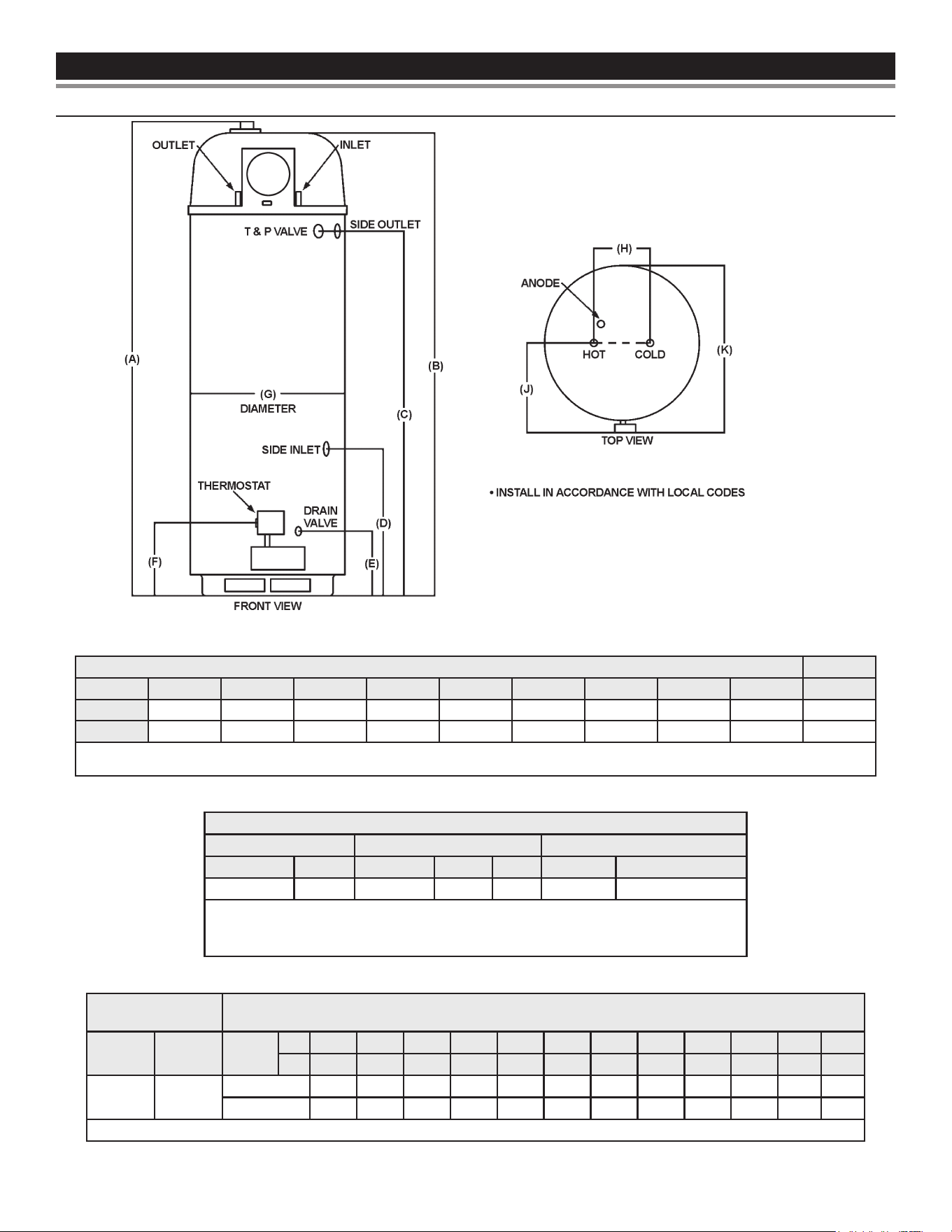
ROUGH-IN DIMENSIONS
Figure 5. Rough-In Dimensions Diagram
Table 1. Rough-In-Dimensions
Units A B C D E F G H J K
Inches
71-1/8 68-3/4 51-7/8 20-7/8 9-1/8 12.5 22 8 15.5 26-5/8
cm
180.64 174.50 131.83 53.09 23.24 31.75 55.88 20.32 39.37 67.63
Top/Side Inlet and Outlet: 3/4″ NPT
Gas Inlet: 1/2” NPT
Table 2. Capacity, Gas and Electrical Characteristics
Approximate Capacity *Manifold Pressure Electrical Characteristics
U.S. Gals. Liters Gas Type “WC kPA Volts/Hz Amperes
50 189 Nat. 4.00 0.99 120/60 <5
All models - Maximum Supply Pressure: 14 inches W.C. (3.48 kPa)
Minimum Supply Pressure for Natural Gas: 5.0 inches W.C. (1.24 kPa)
Minimum pressure must be maintained under both load and no load (dynamic and static) conditions.
Input Table 3. Recovery Capacities - U.S. Gallons/Hr. and Liters/Hr. at Temperature Rise Indicated
Rating
(Btu/hr)
Rating
(kW)
Temp.
Rise
F 30 40 50 60 70 80 90 100 110 120 130 140
C 17 22 28 33 39 44 50 56 61 67 72 78
76,000 22.3
GPH 286 215 172 143 123 107 95 86 78 72 66 61
LPH 1084 813 651 542 465 407 361 325 296 271 250 232
Recovery capacity based on 94% thermal eciency.
9
LOCATING THE NEW WATER HEATER
Carefully choose an indoor location for the new water heater,
because the placement is a very important consideration for the
safety of the occupants in the building and for the most economical
use of the appliance. This water heater is not for use in manufactured
(mobile) homes or outdoor installation.
Whether replacing an old water heater or putting the water heater
in a new location, the following critical points must be observed:
1. Select a location indoors as close as practical to the vent terminal
or location to which the water heater vent piping is going to be
connected, and as centralized with the water piping system as
possible.
2. Selected location must provide adequate clearances for servicing
and proper operation of the water heater.
Property Damage Hazard
All water heaters eventually leak.
•
Do not install without adequate drainage.
•
CAUTION
Installation of the water heater must be accomplished in such a
manner that if the tank or any connections should leak, the ow
will not cause damage to the structure. For this reason, it is not
advisable to install the water heater in an attic or upper oor. When
such locations cannot be avoided, a metal drain pan should be
installed under the water heater. Drain pans are available at your local
hardware store. Such a drain pan must have a clearance of at least
1.0” (2.5cm) greater than any point on the water heater’s outer jacket
and must be piped to an adequate drain. The pan must not restrict
combustion air ow. For example, if a circular pan is used, it must
be a minimum of 27” (69cm) in diameter. See
Figure 1
(page 7).
Water heater life depends upon water quality, water pressure and
the environment in which the water heater is installed. Water heaters
are sometimes installed in locations where leakage may result in
property damage, even with the use of a drain pan piped to a drain.
However, unanticipated damage can be reduced or prevented by
a leak detector or water shutto device used in conjunction with a
piped drain pan. These devices are available from some plumbing
supply wholesalers and retailers, and detect and react to leakage
in various ways:
• Sensors mounted in the drain pan that trigger an alarm or turn o
the incoming water to the water heater when leakage is detected.
• Sensors mounted in the drain pan that turn o the water supply
to the entire building when water is detected in the drain pan.
• Water supply shutto devices that activate based on the water
pressure dierential between the cold water and hot water pipes
connected to the water heater.
• Devices that will turn o the gas supply to a gas water heater
while at the same time shutting o its water supply.
INSTALLATIONS IN AREAS WHERE FLAMMABLE LIQUIDS
(VAPORS) ARE LIKELY TO BE PRESENT OR STORED
(GARAGES, STORAGE AND UTILITY AREAS, ETC.): Flammable
liquids (such as gasoline, solvents, propane (LP or butane, etc.) and
other substances (such as adhesives, etc.) emit ammable vapors
which can be ignited by a gas water heater’s hot surface igniter or
main burner. The resulting ashback and re can cause death or
serious burns to anyone in the area.
Also, the water heater must be located and/or protected so it is not
subject to physical damage by a moving vehicle.
Fire or Explosion Hazard
Read instruction manual before
installing, using or servicing
water heater.
Avoid all ignition sources if you smell gas.
Do not store or use gasoline or other flammable vapors and
liquids in the vicinity of this or any other appliance.
Use only the gas shown on the water heater rating label.
Keep ignition sources away from faucets after extended
periods of non-use.
Maintain required clearances to combustibles.
Do not expose water heater controls to excessive gas
pressure.
Flammable Vapors
FLAMMABLES
DANGER
Vapors from flamable
liquids may explode
and catch fire causing
death or sever burns.
Water heater has a main
burner and ignition device.
The ignition device:
1. Can come on at any time.
2. Will ignight flammable
vapors.
Do not use or store flammable
products, such as gasoline,
solvents, or adhesives in the
same room or area near the
water heater.
Keep flamable products:
1. Fare away from heater.
2. In approved containers.
3. Tightly closed and
4. Out of children’s reach
Vapors:
1. Cannot be seen.
2. Are Heavier than air.
3. Go a long way on the floor.
4. Can be carried from other
rooms to the ignition
device by air currents.
Installation:
Do not install the water heater where flamable products will be
stored or used unless the main burner and hot surface igniter
are at least 18” (457 cm) above the floor. This will reduce, but
not eliminate the risk of vapors being ignited by the main
burner or hot surface igniter.
10
Fire Hazard
For continued protection against risk
of fire:
• Do not install water heater on
carpeted floor.
• Do not operate water heater if any
part has been exposed to flooding
or water damage.
This water heater must not be installed directly on carpeting.
Carpeting must be protected by metal or wood panel beneath the
appliance extending beyond the full width and depth of the appliance
by at least 3” (7.6 cm) in any direction, or if the appliance is installed
in an alcove or closet, the entire oor must be covered by the panel.
Failure to heed this warning may result in a re hazard.
Fire and Explosion Hazard
• Improper use can result in fire or
explosion.
Read the instruction manual before
installing, using, or servicing the water
heater.
• Maintain required clearances to
combustibles.
Minimum clearances between water heater and combustible
construction are 0 inch at the sides and rear, 5.5” (14.0 cm) from the
front and 12” (30.5 cm) from top. (Standard clearance.) If clearances
stated on the heater dier from standard clearances, install water
heater according to clearances stated on the heater.
Adequate clearance 24” (61.0 cm) for servicing this appliance should
be considered before installation, such as changing the anodes, etc.
A minimum clearance of 5.5” (14.0 cm) must be allowed for access
to replaceable parts such as thermostats, drain valve, relief valve
and condensate drain.
When installing the heater, consideration must be given to proper
location. Location selected should be as close to the wall as
practicable and as centralized with the water piping system as
possible.
Figure 6. Wall Clearences for Water Heater Installed in a Closet.
A gas water heater cannot operate properly without the correct
amount of air for combustion. Do not install in a conned area such
as a closet, unless you provide air as shown in
Locating the New Water
Heater
(page 10). Never obstruct the ow of ventilation air. If you
have any doubts or questions at all, call your gas supplier. Failure
to provide the proper amount of combustion air can result in a re or
explosion and cause death, serious bodily injury, or property damage.
Figure 7. Air Vent Requirements for Installation in Closet with Door
If this water heater will be used in beauty shops, barber shops,
cleaning establishments, or self-service laundries with dry cleaning
equipment, it is imperative that the water heater or water heaters
be installed so that combustion and ventilation air be taken from
outside these areas.
Propellants of aerosol sprays and volatile compounds, (cleaners,
chlorine based chemicals, refrigerants, etc.) in addition to being
highly ammable in many cases, will also react to form corrosive
hydrochloric acid when exposed to the combustion products of
the water heater. The results can be hazardous, and also cause
product failure.
INSULATION BLANKETS
Insulation blankets are available to the general public for external
use on gas water heaters but are not necessary with these products.
The purpose of an insulation blanket is to reduce standby heat loss
encountered with storage tank heaters. Your water heater meets or
exceeds the Energy Policy Act standards with respect to insulation
and standby loss requirements, making an insulation blanket
unnecessary.
Should you choose to apply an insulation blanket to this heater, you
should follow these instructions (For identication of components
mentioned below. See
Figure 1
(page 7). Failure to follow these
instructions can restrict the air ow required for proper combustion,
potentially resulting in re, asphyxiation, serious personal injury or
death.
11
Do not obstruct water heater air intake
with insulating blanket.
Gas and carbon monoxide detectors
are available.
Install water heater in accordance with
the instruction manual.
Breathing carbon monoxide can cause brain damage or
death. Always read and understand instruction manual.
Breathing Hazard - Carbon Monoxide Gas
• Do not apply insulation to the top of the water heater, as this will
interfere with safe operation of the blower assembly.
• Do not cover the outer door, thermostat or temperature &
pressure relief valve.
• Do not allow insulation to come within 2” (5.1 cm) of the oor to
prevent blockage of combustion air ow to the burner.
• Do not cover the instruction manual. Keep it on the side of the
water heater or nearby for future reference.
• Do obtain new warning and instruction labels from the
manufacturer for placement on the blanket directly over the
existing labels.
• Do inspect the insulation blanket frequently to make certain it
does not sag, thereby obstructing combustion air ow.
12
INSTALLATION REQUIREMENTSINSTALLATION REQUIREMENTS
WATER PIPING
Water temperature over 125°F (52°C)
can cause severe burns instantly
resulting in severe injury or death.
Children, the elderly and the physically
or mentally disabled are at highest risk
for scald injury.
Feel water before bathing or showering.
Temperature limiting devices such as
point-of-use mixing valves must be
installed when required by codes and to
ensure safe temperatures at fixtures.
HOTTER WATER CAN SCALD
Water heaters are intended to produce hot water. Water heated to
a temperature which will satisfy space heating, clothes washing,
dish washing, cleaning and other sanitizing needs can scald and
permanently injure you upon contact. Some people are more likely
to be permanently injured by hot water than others. These include
the elderly, children, the inrm, or physically/mentally handicapped.
If anyone using hot water ts into one of these groups or if there is
a local code or state law requiring a certain temperature water at the
hot water tap, then you must take special precautions.
In addition to using lowest possible temperature setting that
satises your hot water needs, a means such as a mixing valve,
for example, can be used at hot water taps used by these people
or at the water heater. See
Figure 2
(page 8).
Check State and/or local codes for mixing valve requirements and
installation practices.
Consult a Qualied Installer or Service Agency. Follow manufacturer’s
instructions for installation of valves. Before changing the factory
setting on thermostat, read
Temperature Regulation
(page 31).
Toxic Chemical Hazard
WARNING
● Do not connect to non-potable water
system.
This water heater should not be connected to any heating systems
or component(s) used with a non-potable water heating appliance.
All piping components connected to this unit for space heating
applications should be suitable for use with potable water.
Toxic chemicals, such as those used for boiler treatment should not
be introduced into this system.
When the system requires water for space heating at temperatures
higher than required for domestic water purposes, a mixing
valve must be installed. See
Figure 2
(page 8) for suggested
piping arrangement.
This water heater cannot be used in space heating applications only.
THERMOSTATIC POINT-OF-USE MIXING VALVES
Water temperature over 125°F (52°C)
can cause severe burns instantly
resulting in severe injury or death.
Children, the elderly and the physically
or mentally disabled are at highest risk
for scald injury.
Feel water before bathing or showering.
Temperature limiting devices such as
point-of-use mixing valves must be
installed when required by codes and to
ensure safe temperatures at fixtures.
Water heated to a temperature which will satisfy clothes washing,
dish washing, and other sanitizing needs can scald and cause
permanent injury upon contact. Short repeated heating cycles caused
by small hot water uses can cause temperatures at the point of use
to exceed the water heater’s temperature setting.
Some people are more likely to be permanently injured by hot water
than others. These include the elderly, children, the inrm and the
physically/mentally disabled. Table 1 shows the approximate time-
to-burn relationship for normal adult skin. If anyone using hot water
provided by the water heater being installed ts into one of these
groups or if there is a local code or state law requiring a certain
water temperature at the point of use, then special precautions
must be taken.
In addition to using lowest possible temperature setting that
satises your hot water needs, a means such as a mixing valve,
for example, can be used at hot water taps used by these people
or at the water heater. See
Figure 2
(page 8).
Check State and/or local codes for mixing valve requirements and
installation practices.
Mixing valves are available at plumbing supply stores. Consult
a Qualified Installer or Service Agency. Follow mixing valve
manufacturer’s instructions for installation of the valves.
Table 4. Time to Burn at Dierent Temperatures
Water Temperature
°F (°C)
Time for 1st Degree
Burn
(Less Severe Burns)
Time for Permanent
Burns
2nd & 3rd Degree
(Most Severe Burns
110 (43.3) (normal shower temp.)
116 (46.7) (pain threshold)
116 (46.7) 35 minutes 45 minutes
122 (50) 1 minute 5 minutes
131 (55) 5 seconds 25 seconds
140 (60) 2 seconds 5 seconds
149 (65) 1 second 2 seconds
154 (67.8) instantaneous 1 second
(U.S. Government Memorandum, C.P.S.C., Peter L. Armstrong,
Sept. 15, 1978)
SPACE HEATING AND POTABLE WATER SYSTEM
This appliance has been design certied as complying with
American
National Standard/CSA Standard
for water heaters and is considered
suitable for Water (Potable) Heating and Space Heating.
13
Your water heater is equipped with inlet/outlet connections for use
in space heating applications. See
Figure 2
(page 8). If this water
heater is to be used to supply both space heating and potable
(drinking) water, the instructions listed below must be followed:
• Be sure to follow the manual(s) shipped with the air handler or
other type heating system.
• This water heater is not to be used as a replacement for an
existing boiler installation.
• Do not use with piping that has been treated with chromates,
boiler seal or other chemicals and do not add any chemicals to
the water heater piping
• If the space heating system requires water temperatures in
excess of 120°F (49°C), a mixing valve must be installed per the
manufacturer’s instructions in the potable hot water supply to
limit the risk of scald injury.
• Pumps, valves, piping and ttings must be compatible with
potable water.
• A properly installed ow control valve is required to prevent
thermosiphoning. Thermosiphoning is the result of a continuous
ow of water through the air handler circuit during the o cycle.
Weeping (blow o) of the temperature and pressure relief valve
(T & P) or higher than normal water temperatures are the rst
signs of thermosiphoning.
• The hot water line from the water heater should be vertical past
any mixing valve or supply line to the heating system to remove
air bubbles from the system.
• Do not connect the water heater to any system or components
previously used with non-potable water heating appliances when
used to supply potable water.
Burn Hazard
If the space heating system requires water
temperatures in excess of 129 °F, install
thermostatic mixing valves according to the
manufacturer’s instructions, in the potable hot
water supply at each point of use to limit the
risk of scald injury.
CLOSED WATER SYSTEMS
Water supply systems may, because of code requirements or such
conditions as high line pressure, among others, have installed
devices such as pressure reducing valves, check valves, and back
ow preventers. Devices such as these cause the water system to
be a closed system.
THERMAL EXPANSION
As water is heated, it expands (thermal expansion). In a closed
system the volume of water will grow when it is heated. As the
volume of water grows there will be a corresponding increase in
water pressure due to thermal expansion. Thermal expansion can
cause premature tank failure (leakage). This type of failure is not
covered under the limited warranty. Thermal expansion can also
cause intermittent Temperature-Pressure Relief Valve operation:
water discharged from valve due to excessive pressure build
up. This condition is not covered under the limited warranty. The
Temperature-Pressure Relief Valve is not intended for constant relief
of thermal expansion.
A properly sized thermal expansion tank must be installed on all
closed systems to control the harmful eects of thermal expansion.
Contact a local plumbing service agency to have a thermal expansion
tank installed.
Note: To protect against untimely corrosion of hot and cold water
ttings, it is strongly recommended that di-electric unions or
couplings be installed on this water heater when connected
to copper pipe.
All gas piping must comply with local codes and ordinances or with
the
National Fuel Gas Code (ANSI Z223.1/ NFPA-54)
. Copper and brass
tubing and ttings (except tin lined copper tubing) should not be used.
Property Damage Hazard
● Avoid water heater damage.
● Install thermal expansion tank if necessary.
● Do not apply heat to cold water inlet.
● Contact qualified installer or service agency.
CAUTION
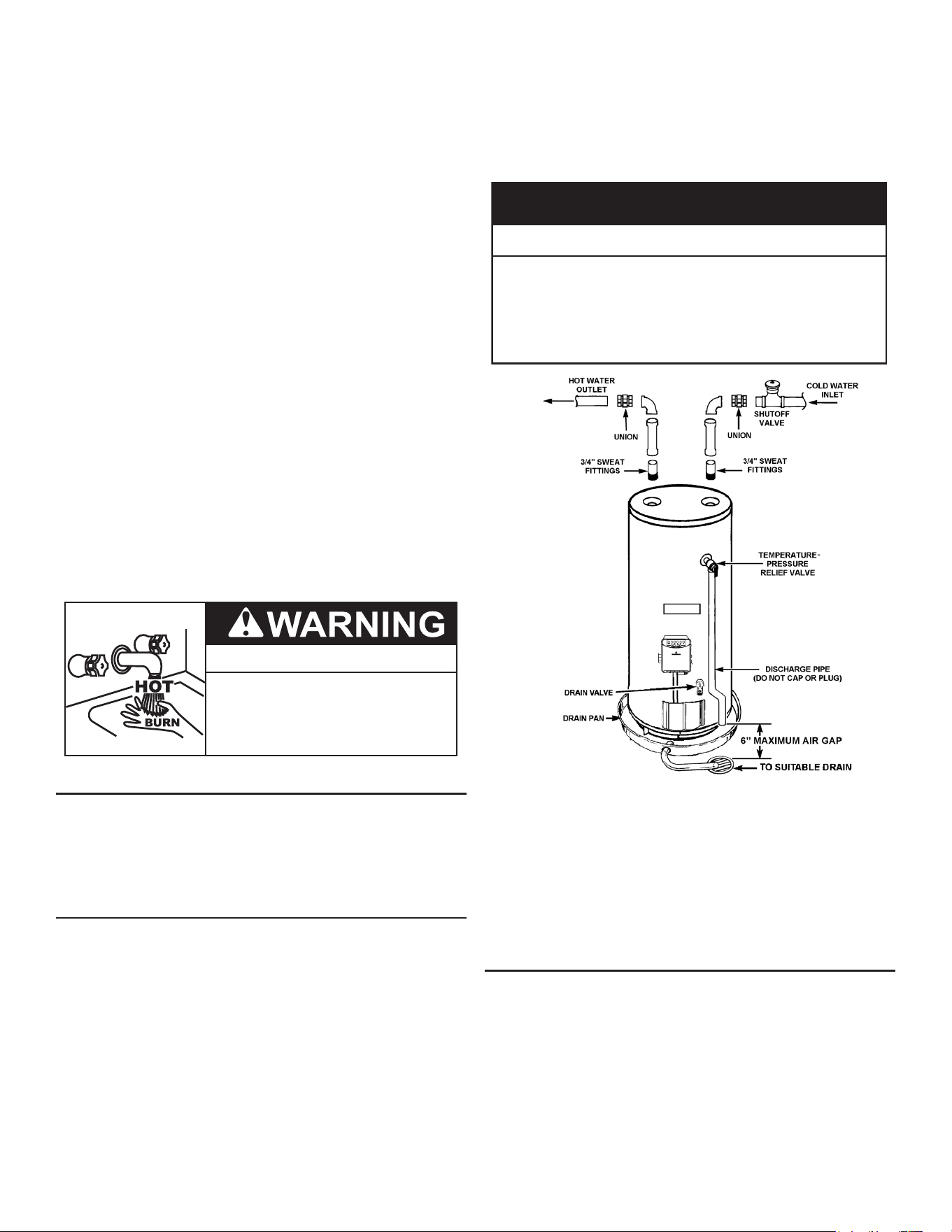
Figure 8. Typical Attachment of Water Piping to the Water Heater
Figure 8
shows typical attachment of water piping to the water heater.
The water heater is equipped with 3/4 inch NPT water connections.
Note: If using copper tubing, solder tubing to an adapter before
attaching the adapter to the water heater connections.
Do not solder the water lines directly to the water heater
connections. It will harm the dip tube and damage the
tank.
INSTALLING T&P VALVE AND PIPE INSULATION (IF SUP-
PLIED)
1. Locate the temperature and pressure relief valve on the water
heater (also known as a T&P relief valve). See
Figure 9
(page
15).
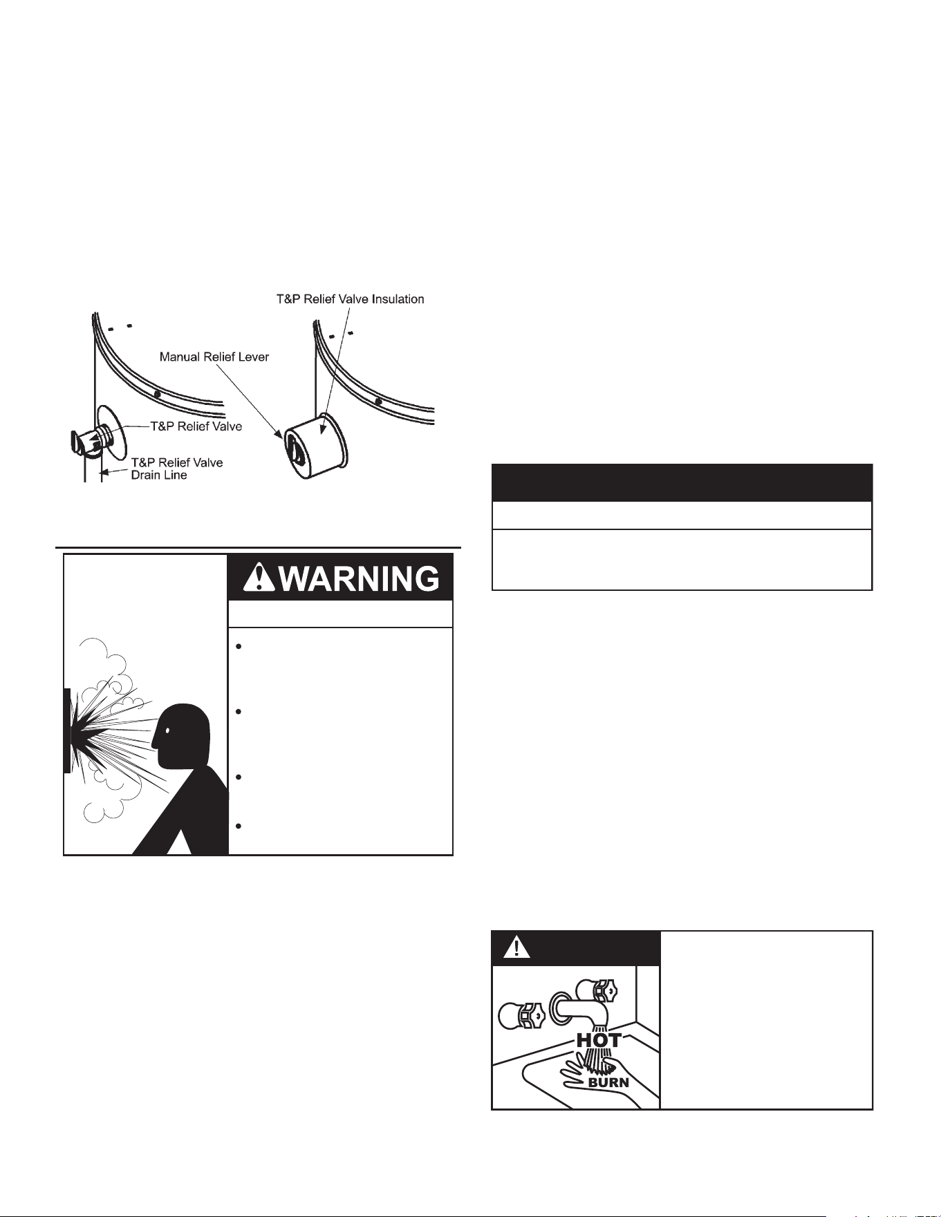
2. Locate the slit running the length of the T&P relief valve insulation.
3. Spread the slit open and t the insulation over the T&P relief valve.
See
Figure 9
(page 15). Apply gentle pressure to the insulation to
ensure that it is fully seated on the T&P Relief Valve. Once seated,
secure the insulation with duct tape, electrical tape, or equivalent.
Important: The insulation and tape must not block the
discharge opening or hinder access to the manual
relief lever. See
Figure 9
(page 15). Ensure
a discharge pipe is installed into the T&P valve
14
discharge opening per the instructions in this
manual.
4. Locate the hot water (outlet) & cold water (inlet) pipes to the
water heater.
5. Locate the slit running the length of a section of pipe insulation.
6. Spread the slit open and slip the insulation over the cold water
(inlet) pipe. Apply gentle pressure along the length of the insulation
to ensure that it is fully seated around the pipe. Also, ensure that
the base of the insulation is ush with the water heater. Once
seated, secure the insulation with duct tape, electrical tape, or
equivalent.
7. Repeat steps 5 and 6 for the hot water (outlet) pipe.
8. Add additional sections of pipe insulation as needed.
Figure 9. Installing Insulation for the T&P Valve
TEMPERATURE-PRESSURE RELIEF VALVE
Explosion Hazard
Temperature-Pressure Relief Valve
must comply with ANSI Z21.22-
CSA 4.4 and ASME code.
Properly sized temperature-
pressure relief valve must be
installed in opening provided.
Can result in overheating and
excessive tank pressure.
Can cause serious injury or death.
This water heater is provided with a properly rated/sized and certied
combination Temperature-Pressure Relief Valve (T&P valve) by
the manufacturer. The valve is certied by a nationally recognized
testing laboratory that maintains periodic inspection of production of
listed equipment of materials as meeting the requirements for
Relief
Valves for Hot Water Supply Systems, ANSI Z21.22 • CSA 4.4
, and the code
requirements of
ASME
.
If replaced, the new T&P valve must meet the requirements of local
codes, but not less than a combination Temperature-Pressure Relief
Valve rated/sized and certied as indicated in the above paragraph.
The new valve must be marked with a maximum set pressure not to
exceed the marked hydrostatic working pressure of the water heater
(150 psi = 1,035 kPa) and a discharge capacity not less than the
water heater Btu/hr or kW input rate as shown on the water heater’s
model rating plate.
Note: In addition to the factory installed Temperature-Pressure
Relief Valve on the water heater, each remote storage
tank that may be installed and piped to a water heating
appliance must also have its own properly sized, rated and
approved Temperature-Pressure Relief Valve installed. Call
the toll free technical support phone number listed on the
back cover of this manual for technical assistance in sizing
a Temperature-Pressure Relief Valve for remote storage
tanks.
For safe operation of the water heater, the Temperature-Pressure
Relief Valve must not be removed from its designated opening nor
plugged. The Temperature-Pressure Relief Valve must be installed
directly into the tting of the water heater designed for the relief valve.
Install discharge piping so that any discharge will exit the pipe within
6 inches (15.2 cm) above an adequate oor drain, or external to the
building. In cold climates it is recommended that it be terminated at
an adequate drain inside the building. Be certain that no contact is
made with any live electrical part. The discharge opening must not
be blocked or reduced in size under any circumstances. Excessive
length, over 30 feet (9.14 m), or use of more than four elbows can
cause restriction and reduce the discharge capacity of the valve.
No valve or other obstruction is to be placed between the
Temperature-Pressure Relief Valve and the tank. Do not connect
discharge piping directly to the drain unless a 6” (15.2 cm) air gap is
provided. To prevent bodily injury, hazard to life, or property damage,
the relief valve must be allowed to discharge water in adequate
quantities should circumstances demand. If the discharge pipe is
not connected to a drain or other suitable means, the water ow may
cause property damage.
CAUTION
•
Temperature-Pressure Relief Valve discharge
pipe must terminate at adequate drain.
Water Damage Hazard
T&P Valve Discharge Pipe Requirements:
• Should not be smaller in size than the outlet pipe size of the valve,
or have any reducing couplings or other restrictions.
• Should not be plugged or blocked.
• Should not be exposed to freezing temperatures.
• Should be of material listed for hot water distribution.
• Should be installed so as to allow complete drainage of both
the Temperature-Pressure Relief Valve and the discharge pipe.
• Must terminate a maximum of six inches above a oor drain or
external to the building. In cold climates, it is recommended that
the discharge pipe be terminated at an adequate drain inside
the building.
• Should not have any valve or other obstruction between the relief
valve and the drain.
DANGER
• Burn hazard.
• Hot water discharge.
• Keep clear of Te mperature-
Pressure Relief Valve
discharge outlet.
The Temperature-Pressure Relief Valve must be manually operated
at least twice a year. Caution should be taken to ensure that (1) no
15
one is in front of or around the outlet of the Temperature-Pressure
Relief Valve discharge line, and (2) the water manually discharged
will not cause any bodily injury or property damage because the
water may be extremely hot. If after manually operating the valve, it
fails to completely reset and continues to release water, immediately
close the cold water inlet to the water heater, follow the draining
instructions in this manual, and replace the Temperature-Pressure
Relief Valve with a properly rated/sized new one.
Note: The purpose of a Temperature-Pressure Relief Valve
is to prevent excessive temperatures and pressures in
the storage tank. The T&P valve is not intended for the
constant relief of thermal expansion. A properly-sized
thermal expansion tank must be installed on all closed
systems to control thermal expansion. See
Closed Water
Systems
(page 14)
and
Thermal Expansion
(page 14).
If you do not understand these instructions or have any questions
regarding the Temperature-Pressure Relief Valve call the toll
free number listed on the back cover of this manual for technical
assistance.
CHEMICAL VAPOR CORROSION
CORROSION OF THE FLUEWAYS AND VENT SYSTEM MAY
OCCUR IF AIR FOR COMBUSTION CONTAINS CERTAIN
CHEMICAL VAPORS. SUCH CORROSION MAY RESULT IN
FAILURE AND RISK OF ASPHYXIATION.
Spray can propellants, cleaning solvents, refrigerator and air
conditioning refrigerants, swimming pool chemicals, calcium and
sodium chloride (water softener salt), waxes, and process chemicals
are typical compounds which are potentially corrosive.
Do not store products of this sort near the heater. Also, air which is
brought in contact with the heater should not contain any of these
chemicals. If necessary, uncontaminated air should be obtained
from remote or outside sources. The limited warranty is voided when
failure of water heater is due to a corrosive atmosphere. (See the
limited warranty for complete terms and conditions).
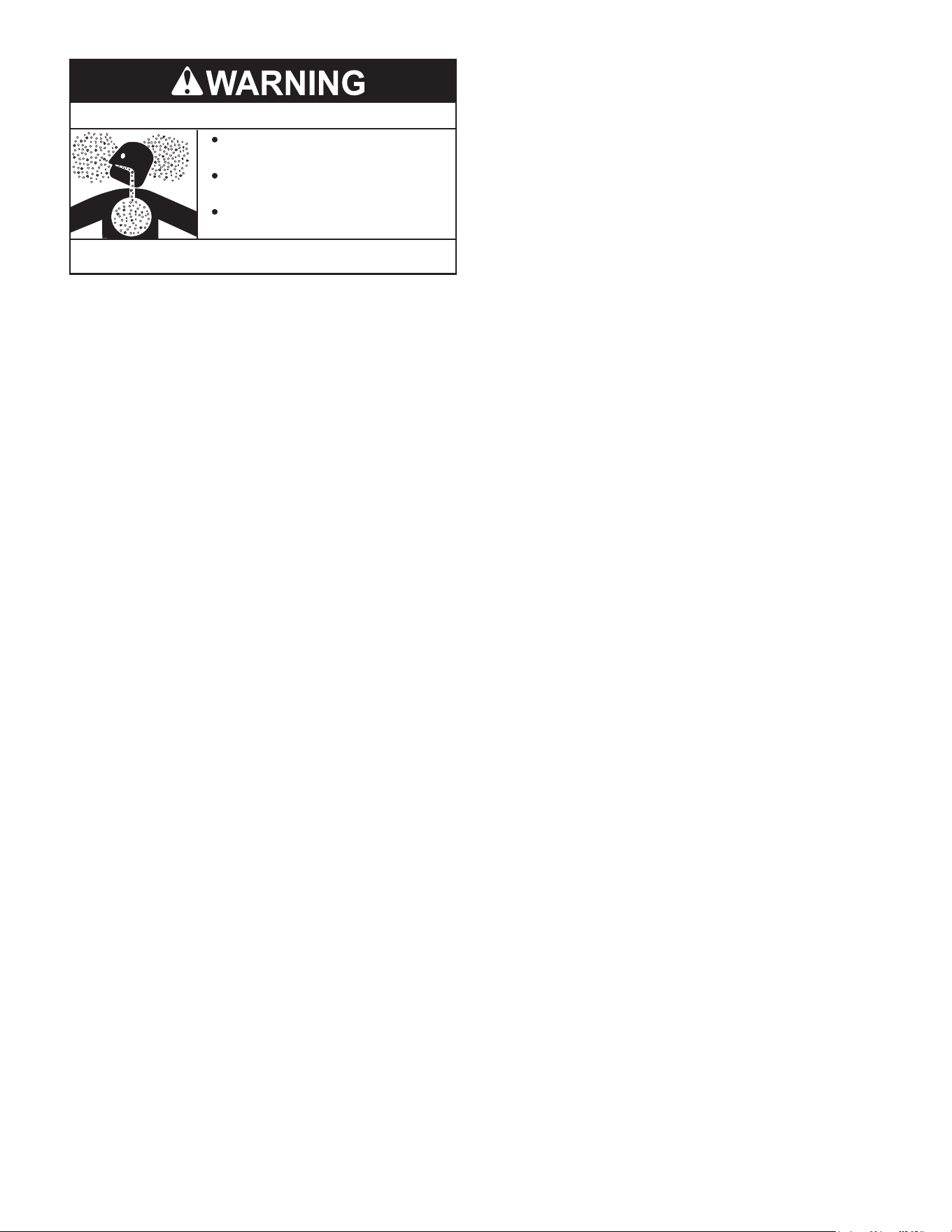
AIR REQUIREMENTS
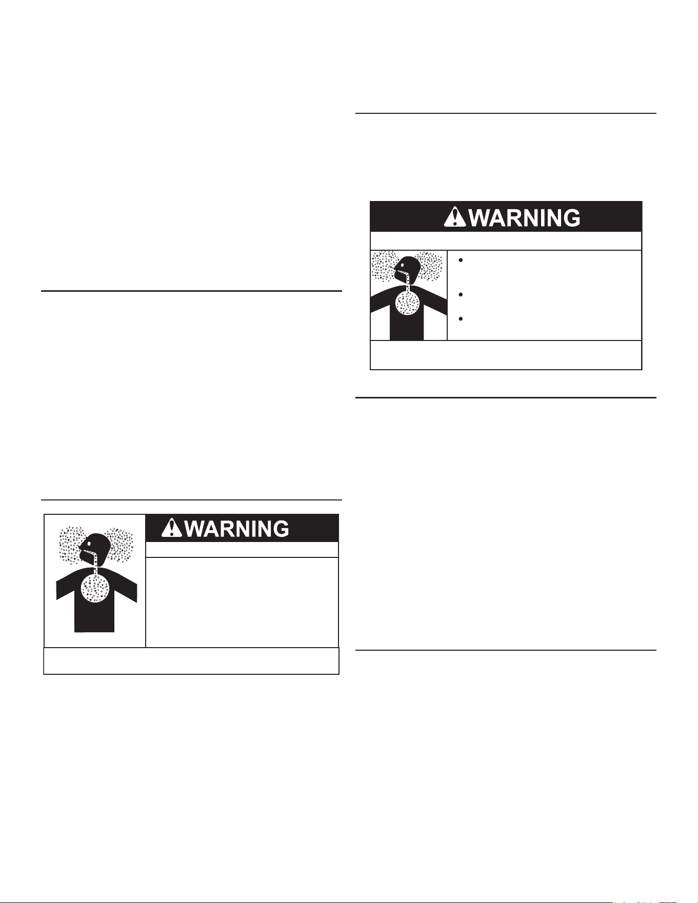
Breathing Hazard
Breathing carbon monoxide can cause brain damage or
death. Always read and understand instruction manual.
•
Install the water heater in accordance with the
instruction manual and NFPA 54.
•
To avoid injury, combustion and ventilation air
must be taken from outdoors.
•
Do not place chemical vapor emitting products
near water heater.
For safe operation an adequate supply of fresh uncontaminated air
for combustion and ventilation must be provided.
An insucient supply of air can cause recirculation of combustion
products resulting in contamination that may be hazardous to life.
Such a condition often will result in a yellow, luminous burner ame,
causing sooting of the combustion chamber, burners and ue tubes
and creates a risk of asphyxiation.
Do not install the water heater in a conned space unless an
adequate supply of air for combustion and ventilation is brought in
to that space using the methods described in the Conned Space
section that follows.
Never obstruct the ow of ventilation air. If you have any doubts or
questions at all, call your gas supplier. Failure to provide the proper
amount of combustion air can result in a re or explosion and cause
property damage, serious bodily injury or death.
COMBUSTION AIR AND VENTILATION
A gas water heater cannot operate properly without the correct
amount of air for combustion. Do not install in a conned area such
as a closet, unless you provide air as shown in
Locating the Water
Heater
(page 10). Never obstruct the ow of ventilation air. If you
have any doubts or questions at all, call your gas supplier. Failure
to provide the proper amount of combustion air can result in a re or
explosion and cause death, serious bodily injury, or property damage.
Breathing Hazard - Carbon Monoxide Gas
Install water heater in accordance with
the Instruction Manual and NFPA 54 or
CAN/CSA-B149.1.
To avoid injury, combustion and ventilation
air must be taken from outdoors.
Do not place chemical vapor emitting
products near water heater.
Breathing carbon monoxide can cause brain damage or
death. Always read and understand instruction manual.
UNCONFINED SPACE
An Unconned Space is one whose volume is not less than 50 cubic
feet per 1,000 Btu/hr (4.8 cubic meters per kW) of the total input
rating of all appliances installed in the space. Rooms communicating
directly with the space, in which the appliances are installed, through
openings not furnished with doors, are considered a part of the
unconned space.
Makeup air requirements for the operation of exhaust fans, kitchen
ventilation systems, clothes dryers and replaces should also be
considered in determining the adequacy of a space to provide
combustion, ventilation and dilution air.
UNUSUALLY TIGHT CONSTRUCTION
In unconned spaces in buildings, inltration may be adequate to
provide air for combustion, ventilation and dilution of ue gases.
However, in buildings of unusually tight construction (for example,
weather stripping, heavily insulated, caulked, vapor barrier, etc.)
additional air must be provided using the methods described in the
Conned Space section that follows.
CONFINED SPACE
A Conned Space is one whose volume is less than 50 cubic feet
per 1,000 Btu/hr (4.8 cubic meters per kW) of the total input rating
of all appliances installed in the space.
Openings must be installed to provide fresh air for combustion,
ventilation and dilution in conned spaces. The required size for the
openings is dependent on the method used to provide fresh air to
the conned space and the total Btu/hr input rating of all appliances
installed in the space.
DIRECT VENT APPLIANCES
Appliances installed in a Direct Vent conguration that derive all
air for combustion from the outdoor atmosphere through sealed
intake air piping are not factored in the total appliance input Btu/hr
calculations used to determine the size of openings providing fresh
air into conned spaces.
16
EXHAUST FANS
Where exhaust fans are installed, additional air should be provided
to replace the exhausted air. When an exhaust fan is installed in
the same space with a water heater, sucient openings to provide
fresh air must be provided that accommodate the requirements for
all appliances in the room and the exhaust fan. Undersized openings
will cause air to be drawn into the room through the water heater’s
vent system causing poor combustion. Sooting, serious damage to
the water heater and the risk of re or explosion may result. It can
also create a risk of asphyxiation.
LOUVERS AND GRILLES
The free areas of fresh air openings in instructions that follow do not
take in to account presence of louvers, grilles or screens in openings.
The required size of openings for combustion, ventilation and dilution
air should be based on the “net free area” of each opening. Where
the free area through a design of louver or grille or screen is known, it
should be used in calculating the size of opening required to provide
the free area specied. Where the louver and grille design and free
area are not known, it should be assumed that wood louvers will
have 25% free area and metal louvers and grilles will have 75%
free area. Non motorized louvers and grilles should be xed in the
open position.
FRESH AIR OPENINGS FOR CONFINED SPACES
The following instructions should be used to calculate the size,
number and placement of openings providing fresh air for combustion,
ventilation and dilution in conned spaces. The illustrations shown
in this section of the manual are a reference for the openings that
provide fresh air into conned spaces only. Do not refer to these
illustrations for the purpose of vent installation. See
Installation of Vent
System
(page 21) for complete venting installation instructions.
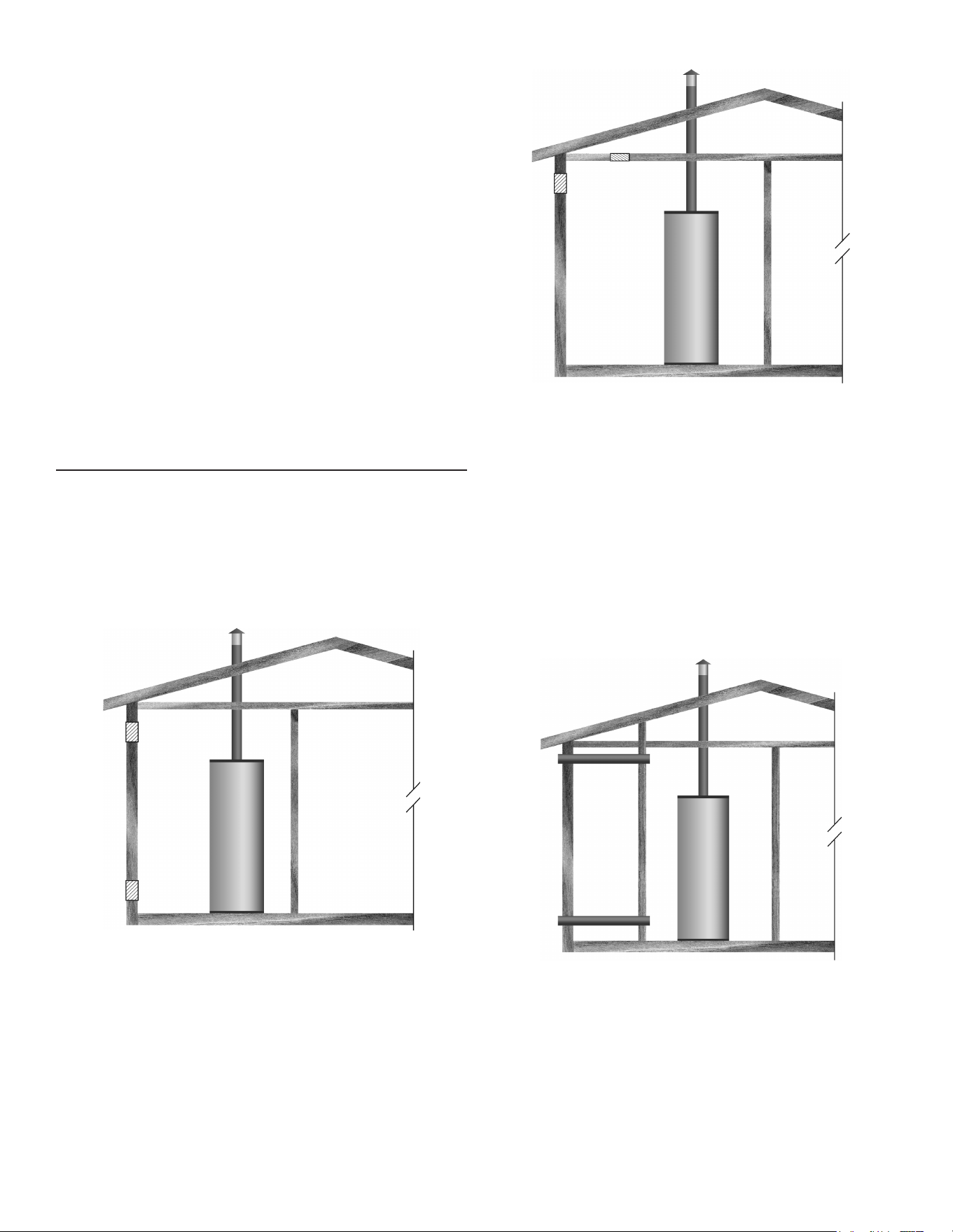
OUTDOOR AIR THROUGH TWO OPENINGS
Figure 10. Outdoor Air Through Two Openings
The confined space should be provided with two permanent
openings, one commencing within 12 inches (300 mm) of the top
and one commencing within 12 inches (300 mm) of the bottom of
the enclosure. The openings should communicate directly with the
outdoors. See
Figure 10.
Each opening should have a minimum free area of 1 square inch
per 4,000 Btu/hr (550 mm
2
per kW) of the aggregate input rating of
all appliances installed in the enclosure. Each opening should not
be less than 100 square inches (645 cm
2
).
OUTDOOR AIR THROUGH ONE OPENING
Figure 11. Outdoor Air Through One Opening
Alternatively a single permanent opening, commencing within 12
inches (300 mm) of the top of the enclosure, should be provided. See
Figure 11
. The water heater should have clearances of at least 1 inch
(25 mm) from the sides and back and 6 inches (150 mm) from the
front of the appliance. The opening should directly communicate with
the outdoors or should communicate through a vertical or horizontal
duct to the outdoors or spaces that freely communicate with the
outdoors and should have a minimum free area of the following:
1. One square inch per 3000 Btu/hr (700 mm
2
per kW) of the total
input rating of all appliances located in the enclosure, and
2. Not less than the sum of the areas of all vent connectors in
space.
OUTDOOR AIR THROUGH TWO HORIZONTAL DUCTS
Figure 12. Outdoor Air Through Two Horizontal Ducts
Conned space should be provided with two permanent horizontal
ducts, one commencing within 12 inches (300 mm) of top and one
commencing within 12 inches (300 mm) of bottom of enclosure.
Horizontal ducts should communicate directly with outdoors. See
Figure 12
.
Each duct opening should have a minimum free area of 1 square
inch per 2,000 Btu/hr (1100 mm
2
per kW) of the aggregate input
rating of all appliances installed in the enclosure.
When ducts are used, they should be of the same cross sectional
area as the free area of the openings to which they connect. The
17
minimum dimension of rectangular air ducts should be not less than
3 inches.
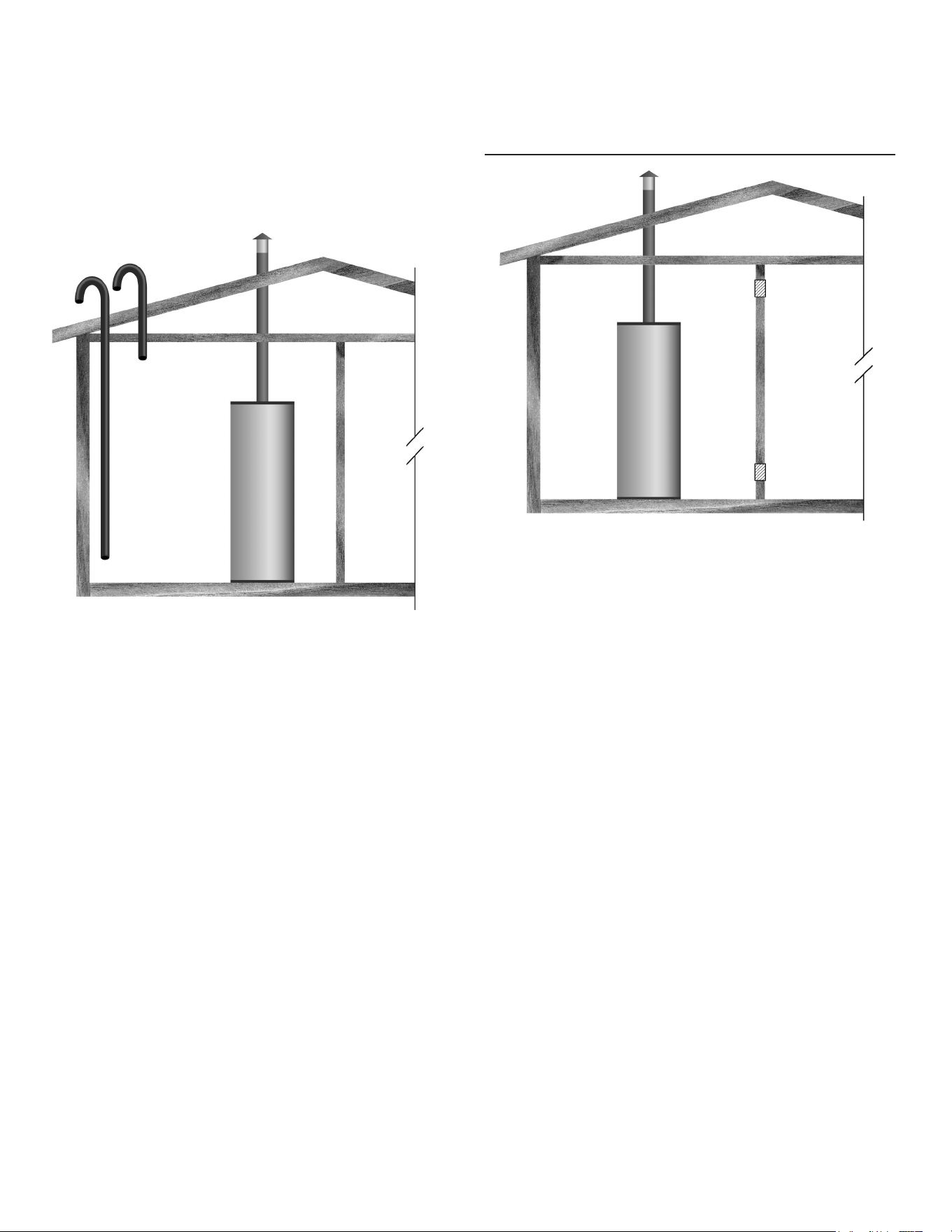
OUTDOOR AIR THROUGH TWO VERTICAL DUCTS
The illustrations shown in this section of the manual are a reference
for the openings that provide fresh air into conned spaces only.
Do not refer to these illustrations for the purpose of vent installation.
See
Installation of Vent System
(page 21) for complete venting
installation instructions.
Figure 13. Outdoor Air Through Two Vertical Ducts
The conned space should be provided with two permanent vertical
ducts, one commencing within 12 inches (300 mm) of the top and
one commencing within 12 inches (300 mm) of the bottom of the
enclosure. The vertical ducts should communicate directly with the
outdoors. See
Figure 13
.
Each duct opening should have a minimum free area of 1 square
inch per 4,000 Btu/hr (550 mm
2
per kW) of the aggregate input rating
of all appliances installed in the enclosure.
When ducts are used, they should be of the same cross sectional
area as the free area of the openings to which they connect. The
minimum dimension of rectangular air ducts should be not less than
3 inches.
AIR FROM OTHER INDOOR SPACES
Figure 14. Air From Other Indoor Spaces
The confined space should be provided with two permanent
openings, one commencing within 12 inches (300 mm) of the top
and one commencing within 12 inches (300 mm) of the bottom of
the enclosure. See
Figure 14
.
Each opening should communicate directly with an additional room(s)
of sucient volume so that the combined volume of all spaces meets
the criteria for an Unconned Space.
Each opening should have a minimum free area of 1 square inch per
1,000 Btu/hr (1100 mm
2
per kW) of the aggregate input rating of all
appliances installed in the enclosure. Each opening should not be
less than 100 square inches (645 cm
2
).
18

INSTALLATION REQUIREMENTS FOR THE COMMONWEALTH OF INSTALLATION REQUIREMENTS FOR THE COMMONWEALTH OF
MASSACHUSETTSMASSACHUSETTS
COMMONWEALTH OF MASSACHUSETTS
For all side wall terminated, horizontally vented power vent, direct
vent, and power direct vent gas fueled water heaters installed in every
dwelling, building or structure used in whole or in part for residential
purposes, including those owned or operated by the Commonwealth
and where the side wall exhaust vent termination is less than seven
(7) feet above nished grade in the area of the venting, including
but not limited to decks and porches, the following requirements
shall be satised:
INSTALLATION OF CARBON MONOXIDE DETECTORS
At the time of installation of the side wall horizontal vented gas fueled
equipment, the installing plumber or gastter shall observe that a
hard wired carbon monoxide detector with an alarm and battery back-
up is installed on the oor level where the gas equipment is to be
installed. In addition, the installing plumber or gastter shall observe
that a battery operated or hard wired carbon monoxide detector
with an alarm is installed on each additional level of the dwelling,
building or structure served by the sidewall horizontal vented gas
fueled equipment. It shall be the responsibility of the property owner
to secure the services of qualied licensed professionals for the
installation of hard wired carbon monoxide detectors.
In the event that the side wall horizontally vented gas fueled
equipment is installed in a crawl space or an attic, the hard wired
carbon monoxide detector with alarm and battery back-up may be
installed on the next adjacent oor level.
In the event that the requirements of this subdivision can not be
met at the time of completion of installation, the owner shall have
a period of thirty (30) days to comply with the above requirements
provided that during said thirty (30) day period, a battery operated
carbon monoxide detector with an alarm shall be installed.
APPROVED CARBON MONOXIDE DETECTORS
Each carbon monoxide detector as required in accordance with
the above provisions shall comply with
NFPA 720
and be
ANSI/UL 2034
listed and
CSA
certied.
SIGNAGE
A metal or plastic identication plate shall be permanently mounted
to the exterior of the building at a minimum height of eight (8) feet
above grade directly in line with the exhaust vent terminal for the
horizontally vented gas fueled heating appliance or equipment. The
sign shall read, in print size no less than one-half (1/2) inch in size,
“gas vent directly below. Keep clear of all obstructions.”
INSPECTION
The state or local gas inspector of the side wall horizontally vented
gas fueled equipment shall not approve the installation unless, upon
inspection, the inspector observes carbon monoxide detectors and
signage installed in accordance with the provisions of 248 CMR
5.08(2)(a) 1 through 4.
EXEMPTIONS
The following equipment is exempt from 248 CMR 5.08(2)(a)1
through 4:
1. The equipment listed in Chapter 10 entitled “Equipment Not
Required To Be Vented” in the most current edition of NFPA 54
as adopted by the Board; and
2. Product Approved side wall horizontally vented gas fueled
equipment installed in a room or structure separate from the
dwelling, building, or structure used in whole or in part for
residential purposes.
MANUFACTURER REQUIREMENTS - GAS EQUIPMENT
VENTING SYSTEM PROVIDED
When the manufacturer of Product Approved side wall horizontally
vented gas equipment provides a venting system design or venting
system components with the equipment, the instructions provided
by the manufacturer for installation of the equipment and the venting
system shall include:
1. Detailed instructions for the installation of the venting system
design or the venting system components; and
2. A complete parts list for the venting system design or venting
system.
MANUFACTURER REQUIREMENTS - GAS EQUIPMENT
VENTING SYSTEM NOT PROVIDED
When the manufacturer of a Product Approved side wall horizontally
vented gas fueled equipment does not provide the parts for venting
the ue gases, but identies “special venting systems,” the following
requirements shall be satised by the manufacturer:
1. The referenced “special venting system” instructions shall
be included with the appliance or equipment installation
instructions; and
2. The “special venting systems” shall be Product Approved by the
Board, and the instructions for that system shall include a parts
list and detailed installation instructions.
A copy of all installation instructions for all Product Approved
side wall horizontally vented gas fueled equipment, all venting
instructions, all parts lists for venting instructions, and/or all
venting design instructions shall remain with the appliance or
equipment at the completion of the installation.
19
VENTING INSTALLATIONVENTING INSTALLATION
APPROVED VENT PIPE MATERIALS:
PVC pipe materials:
• DWV ASTM-D2665 or CSA B181.2
• Schedule 40, 80, 120 ASTM-D1785 or CSA B137.3
• SDR Series ASTM-2241 or CSA B137.3
CPVC pipe materials:
• CPVC 41 ASTM-D2846 or CSA B137.6
• Schedule 40, 80 ASTM-F441 or CSA B137.6
• SDR Series ASTM-F442
ABS pipe materials:
• Schedule 40 DWV ASTM-D2661 or CSA B181.1
Polypropylene - See
Table 7
and
Table 8
(page 27).
• M & G Duravent PolyPro vent system
• Centrotherm InnoFlue vent system
Where applicable, the installation of the venting system should
be done in accordance with the venting system manufacturer’s
instructions.
Note: The use of cellular core PVC (ASTM F891), cellular core
CPVC, or Radel® (polyphenolsulfone) in non-metallic
venting systems is prohibited. Covering non-metallic vent
pipe and ttings with thermal insulation is prohibited.
PVC Materials should use ASTM D-2564 Grade Cement; CPVC
Materials should use ASTM F-493 Grade Cement and ABS
Materials should use ASTM D-2235 Grade Cement.
If water heater is being installed as a replacement for an
existing power vented heater in pre-existing venting, a thorough
inspection of existing venting system must be performed prior
to any installation work. Verify that correct material as detailed
above has been used, and that minimum or maximum vent
lengths and terminal location as detailed in this manual have
been met. Carefully inspect entire venting system for any signs
of cracks or fractures, particularly at joints between elbows
and other ttings and straight runs of vent pipe. Check system
for signs of sagging or other stresses in joints as a result of
misalignment of any components in system. If any of these
conditions are found, they must be corrected in accordance with
venting instructions in this manual before completing installation
and putting water heater into service.
Note: For water heaters in locations with high ambient
temperatures (above 100°F) it is recommended that CPVC
or ABS pipe and ttings be used. B. A 22.5 degree elbow
(2” vent pipe) or a 45 degree elbow (3” and 4” vent pipe)
with an installed screen-vent terminal must be used in all
cases.
Note: There will be some installations where condensate will
be formed in the horizontal runs of the vent system. This
condensate will run into the condensate boot attached to
the blower and out the tting. The water heater is shipped
with condensate hose that attaches to the tting on the
condensate boot. No other Tee or tting is required. See
Figure 15
(page 21),
Figure 17
(page 22) and
Figure 18
(page 23).
PLANNING THE VENT SYSTEM
Plan the route of the vent system from the discharge of the blower
to the planned location of the vent terminal. Water heaters covered
by these instructions are Category IV appliances.
1. Layout total vent system to use a minimum of vent pipe and
elbows. Water heaters covered by these instructions are Category
IV appliances.
2. This water heater is capable of venting ue gases equivalent to
25’ (7.6 m) of 2” pipe, 65’ (19.8 m) of 3” pipe, or 128’ (39.0 m) of
4” pipe as listed in Table 2.
Table 5. Max Pipe Lengths Per Number of 90° Elbows
Number of
90° Elbows
2” Maximum
Pipe - ft. (m)
3” Maximum
Pipe - ft. (m)
4” Maximum
Pipe - ft. (m)
1 20 (6.1) 60 (18.3) 120 (36.6)
2 15 (4.6) 55 (16.8) 112 (34.1)
3 10 (3.0) 50 (15.2) 104 (31.7)
4 -- 45 (13.7) 96 (29.3)
5 -- 40 (12.2) 88 (26.8)
6 -- 35 (10.7) 80 (24.3)
The minimum vent lengths for each of the pipe sizes is one
90° on top of the unit plus 2′ (61cm) of straight pipe and the
appropriate termination.
Note: The equivalent feet (m) of pipe listed above are
exclusive of the termination. That is, the termination,
with an installed screen, is assumed to be in the system
and the remainder of the system must not exceed the
lengths discussed above.
3. The blower discharge adapter is made to accept only straight
sections of 2″ pipe. To start, a minimum of 2 inches (5.1 cm)
of 2″ pipe must be attached to the blower discharge. See
Figure
15
(page 21).
If using 2” inch vent pipe:
A minimum of 2 inches (5.1 cm) must be attached to the blower
before the rst elbow. After the rst elbow add the additional
venting required for the installation. The total system cannot
exceed the lengths discussed above, where each elbow is equal
to 5 feet (1.5 m) of straight pipe. The SS2 tting, if used, counts
as being one 90 degree elbow.
If using 3” or 4” inch vent pipe:
Two inches (5.1 cm) of pipe must be attached to the blower
discharge before adding a reducer to acquire the desired pipe
diameter. An appropriately sized 45 degree schedule 40 DWV
elbow (eld supplied) vent terminal must be obtained with an
equivalent screen (supplied in the vent kit). The total system
cannot exceed the equivalent pipe lengths discussed above
where each elbow is equal to 5 feet (1.5 m) of straight pipe
(3” vent pipe) or 8 feet (2.4 m) of straight pipe (4” vent pipe). The
SS2 tting, if used, counts as one 90 degree elbow.
Do not locate the vent termination over public walkways or a public
area where condensate or vapor can cause a nuisance or ice hazard.
VENT PIPE TERMINATION
The rst step is to determine where the vent pipe will terminate. See
Figure 24
(page 27), 20 and 21. The vent may terminate through
a sidewall as shown in
Figure 17
(page 22) or through the roof as
shown in Figure 21.
20
The vent system must terminate so that proper clearances are
maintained as cited in local codes or the current edition of the
National
Fuel Gas Code
.
Instructions on proper installation through a sidewall are provided
in
Figure 25
(page 28).
Plan the vent system layout so that proper clearances are maintained
from plumbing and wiring.
Vent pipes serving power vented appliances are classied by building
codes as “vent connectors”. Required clearances from combustible
materials must be provided in accordance with information in
Locating
the New Water Heater
(page 10) and
Water Heater Installation
(page
28), and with the
National Fuel Gas Code
and local codes.
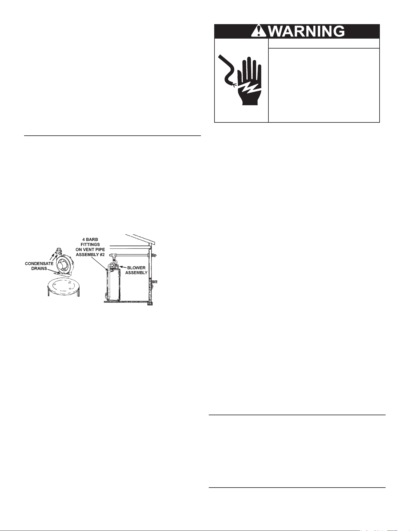
BLOWER ASSEMBLY INSTALLATION
1. This power vented water heater comes with blower assembly
installed.
2. After unit is set in place, make sure blower assembly is still
mounted securely. Also make sure both drain ports of rubber
boot vent adapter are capped o. Lastly, make sure there is no
damage to blower.
3. Condensate drains from three locations on blower assembly.
See
Figure 15
. One exible hose runs from bottom of blower
housing; two run from the ports of rubber connector at the outlet
of blower. All these three condensate hoses are connected to
barb ttings at vent pipe assembly #2. The hose from bottom
of blower housing is clamped by two clamps and the two hoses
from rubber connector are harnessed by another clamp. Make
sure there is no kink or twist.
Figure 15. Blower Assembly Condensate Drains and Barb Fittings
4. Make sure there is no packing material in the inlet or discharge
of the blower.
5. Make sure that the plastic tubing is still attached from the air
pressure switch to the port on the blower housing. Make sure
the plastic tubing is not folded anywhere between the pressure
switch and the blower housing.
6. Make sure the ON/OFF switch is in the OFF position and that the
outer harness is connected from the blower control box to the
connector on the bottom side of the gas valve.
7. If the outer harness is not factory installed, make sure the ON/
OFF switch is in the OFF position and then connect the outer
harness from the blower control box to the connector on the
bottom side of the gas valve.
● Before servicing the water heater, make
sure the blower assembly is unplugged or
the electrical supply to the water heater is
turned OFF.
Electrical Shock Hazard
● Label all wires prior to disconnection when
servicing controls. Wiring errors can cause
improper and dangerous operation. Verify
proper operation after servicing.
● Failure to follow these instructions can
result in personal injury or death.
8. Do not plug in power cord until vent system is completely installed.
The Power Vent operates on 110-120 Vac. therefore a grounded
outlet must be within reach of the 6 foot (1.8 m) exible power
cord supplied with the vent. See
Figure 1
(page 7)
and Figure
2
(page 8). The power cord supplied may be used on a unit
only where local codes permit. If local codes do not permit use
of exible power supply cord:
A. Make sure the unit is unplugged from the wall outlet.
Remove the plastic top cap. Remove screws and open
panel on the front of the control box on the blower.
B. Cut the exible power cord, leaving enough to be able to
make connections. Remove the strain relief tting from
the box.
C. Install a suitable conduit tting inside the enclosure.
D. Splice eld wiring into existing wiring using code authorized
method (wire nuts, etc).
E. Be certain that neutral and line connections are not reversed
when making these connections.
F. Ground heater properly. This water heater must be
grounded in accordance with the
National Electrical Code NFPA
70
or the
Canadian Electrical Code C22.1
and/or local codes.
These must be followed in all cases.
The water heater must be connected to a grounded metal,
permanent wiring system; or an equipment grounding
conductor must be run with the circuit conductors and
connected to the equipment grounding terminal or lead on
the water heater. See
Figure 34
(page 43).
G. Close the panel on the control box. Make sure that the
access panel is secured shut.
9. The blower discharge boot is made to accept only straight
sections of 2” pipe. To start o with an elbow, a short section
of the furnished pipe, a minimum of 2 inches (5.1 cm), must be
cut and glued into the end of the elbow that will mount on the
discharge boot.
VENT SOUND SILENCER
The Vent Sound Silencer (SS2) is optional. It is useful to reduce the
sound level outside, near the vent terminal. The SS2 must always
be installed directly above the blower outlet, with the closed end
horizontal to the ground. See
Figure 1
(page 7)
and Figure 2
(page
8). The closed end that contains the sound absorbing padding
must never be mounted pointed towards the ground since it would ll
with condensate. The SS2 counts as 5 equivalent feet in the overal
length of the vent system.
INSTALLATION OF VENT SYSTEM
Before beginning installation of piping system thoroughly read the
Vent Pipe Preparation
(page 23).
21
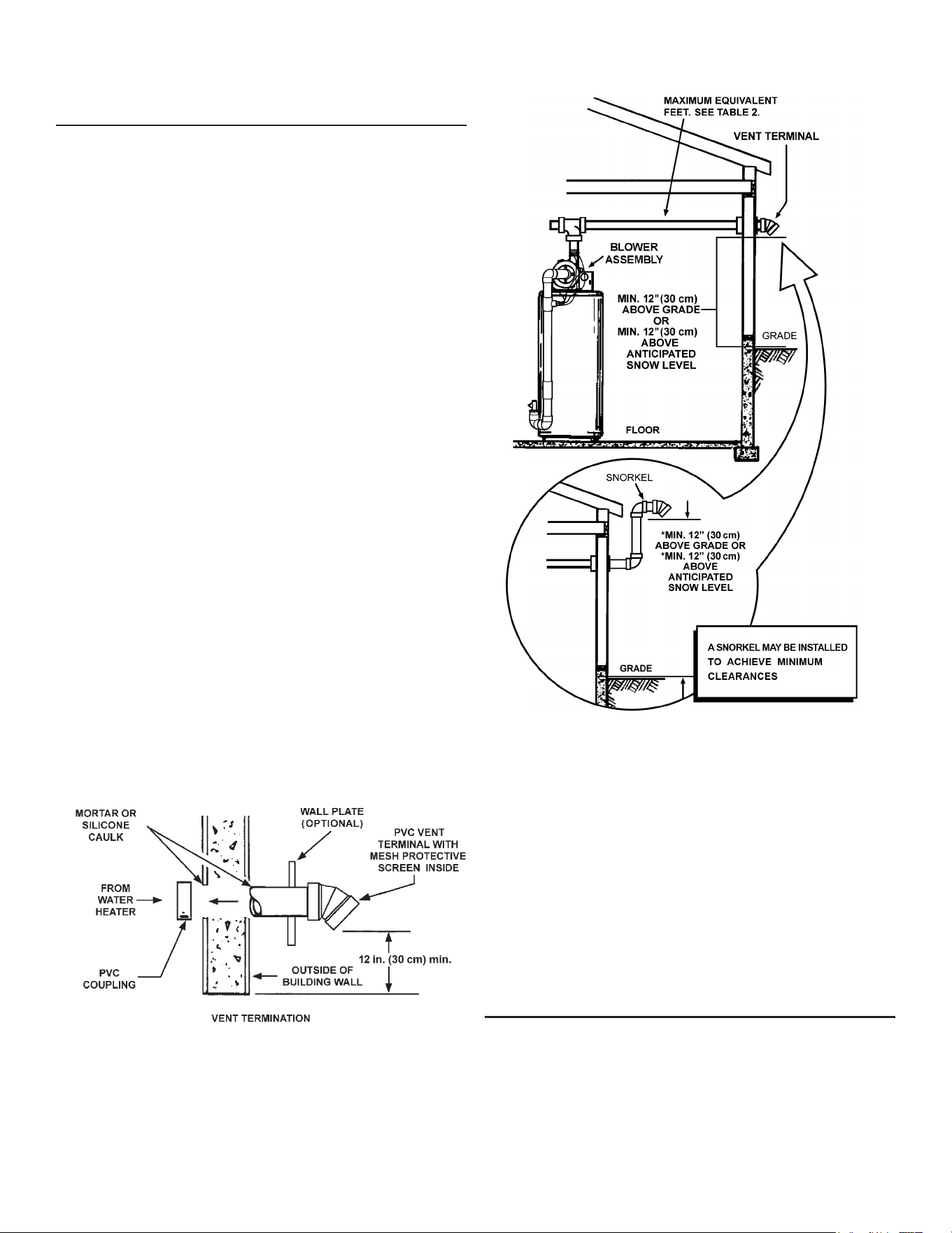
If you are installing your system so that it vents through roof, see
Vertical Vent Termination Installation
(page 22)
.
HORIZONTAL VENT TERMINATION INSTALLATION
1. Install the vent terminal by using the cover plate as a template to
mark the hole for the vent pipe to pass through the wall. BEWARE
OF CONCEALED WIRING AND PIPING INSIDE THE WALL.
2. If the Vent Terminal is being installed on outside of a nished wall,
it may be easier to mark both the inside and outside wall. Align
holes by drilling a hole through center of the template from the
inside through to the outside. The template can now be positioned
on the outside wall using the drilled hole as a centering point for
the template.
A. MASONRY SIDE WALLS
Chisel an opening approximately one half inch (1.3 cm)
larger than the marked circle.
B. WOODEN SIDE WALLS
Drill a pilot hole approximately one quarter inch (0.64 cm)
outside of the marked circle. This pilot hole is used as a
starting point for a saws-all or sabre saw blade. Cut around
the marked circle staying approximately one quarter inch
(0.64 cm) outside of the line. (This will allow the vent to
easily slide through the opening. The resulting gap will be
covered up by the Vent Terminal cover plate.) Repeat this
step on inside wall if necessary.
VENTING INSTALLATION SEQUENCE
1. Cut a length of PVC pipe about 3.5 inches (8.9 cm) longer than
wall thickness at the opening.
2. Glue the vent terminal to this section of pipe.
3. Slide the wall plate over the pipe to stop against the vent terminal.
Place a bead of caulking (not supplied) around the gap between
the pipe and cover plate. Apply enough to ll some of the gap
between the pipe and wall.
4. Place some of the caulking on the back of the plate to hold it
against the wall after installation. If the vent pipe is installed up
to the wall, with a coupling on the end against the wall opening,
the pipe with the vent terminal can be prepared for gluing before
inserting through the wall.
5. Slide the pipe through the wall and insert into the coupling on the
other side of the wall, making sure that the vent terminal ends up
pointed in the correct position. See
Figure 16
.
Figure 16. Sidewall Vent Termination
With the route of the venting system and selection of materials
completed as discussed in
Planning The Vent System
(page 21), the
through-the-wall vent terminal in place, and the rst section of piping
up to rst elbow installed at the blower, it is time to complete the
installation of the venting system for the sidewall installation.
Figure 17. Sidewall Vent Installation Snow Clearances
It is recommended that the completion of the venting system start
at the blower assembly and run to the coupling on the inside wall of
the vent terminal. See
Figure 16
.
The vent system piping should be supported every 5 feet (1.5 m)
of vertical run and every 3 feet (91 cm) of horizontal run. Follow
vent pipe manufacturer’s instructions for proper joining procedures.
If necessary to achieve the 12” minimum clearance above the highest
anticipated snow level, install a snorkel as shown in bottom portion
of
Figure 18
.
Note: With the installation of a snorkel it is necessary to use
two 90° elbows that shall be considered along with the
additional vent pipe when calculating maximum equivalent
feet of venting.
VERTICAL VENT TERMINATION INSTALLATION
A proper ashing or “BOOT” should be used to seal the pipe where it
exits the roof. The total vent system should not exceed the equivalent
feet of pipe as listed in Table 1.
Provide support for all pipe protruding through the roof. All piping should
be properly secured. The vent system piping should be supported
every 5 feet (1.5 m) of vertical run and every 3 feet (91 cm) of
horizontal run. Follow vent pipe manufacturer’s instructions for proper
joining procedures.
22
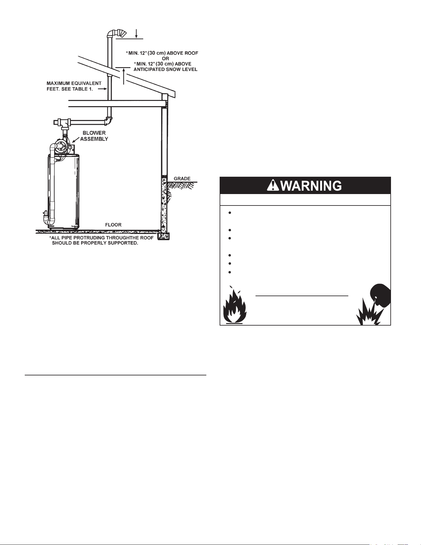
Figure 18. Through-the-Roof Vent Installation
Important: The vent system must terminate so that proper
clearances are maintained as cited in local codes
or the current edition of the
National Fuel Gas Code
(ANSI Z223.1)
or the
Natural Gas and Propane Installation
Code (CAN/CSA-B149.1)
and as listed below:
Note: Vent Termination must extend a minimum of 12 inches (30
cm) above roof or 12 inches (30 cm) above the anticipated
snow level to prevent blockage of the vent termination, as
shown in
Figure 17
and
Figure 18
(page 22).
VENT PIPE PREPARATION
INITIAL PREPARATION
1. Make sure the solvent cement you are planning to use is designed
for the specic application you are attempting.
2. Know the physical and chemical characteristics and limitations of
the PVC and CPVC piping materials that you are about to use.
3. Know the reputation of your manufacturer and their products.
4. Know your own qualications or those of your contractor. The
solvent welding technique of joining PVC and CPVC pipe is a
specialized skill just as any other pipe tting technique.
5. Closely supervise the installation and inspect the nished job
before start-up.
A. Contact the manufacturer, supplier, or competent consulting
agency if you have any questions about the application or
installation of PVC and CPVC pipe.
B. Take the time and eort to do a professional job. Shortcuts
will only cause you problems and delays in start-up. By
far, the majority of failures in PVC and CPVC systems are
the result of shortcuts and/or improper joining techniques.
6. Selection of Materials
• Cutting Device - Saw or Pipe Cutter
• Deburring Tool, Knife, File, or Beveling Machine (2” and
above)
• Brush - Pure Bristle
• Rag - Cotton (Not Synthetic)
• Primer and Cleaner
• Solvent Cement - PVC for PVC Components and CPVC
for CPVC Components
• Containers - Metal or Glass to hold Primer and Cement.
Select the type of PVC or CPVC materials to be used
on the basis of their application with respect to chemical
resistance, pressure rating, temperature characteristics,
etc.
• Insertion Tool - Helpful for larger diameter pipe and t-
tings 6 inches (15.2 cm) and above.
Fire or Explosion Hazard
Read instruction manual before
installing, using or servicing
water heater.
Avoid all ignition sources if you smell gas.
Do not store or use gasoline or other flammable vapors and
liquids in the vicinity of this or any other appliance.
Use only the gas shown on the water heater rating label.
Keep ignition sources away from faucets after extended
periods of non-use.
Maintain required clearances to combustibles.
Do not expose water heater controls to excessive gas
pressure.
Primer
It is recommended that Tetrahydrofuran (THF) be used to
prepare the surfaces of pipe and ttings for solvent welding.
Do not use water, rags, gasoline or any other substitutes for
cleaning PVC or CPVC surfaces. A chemical cleaner such as
MEK may be used.
Cement
The cement should be a bodied cement of approximately 500
to 1600 centipoise viscosity containing 10-20% (by weight)
virgin PVC material solvated with tetrahydrofuran (THF). Small
quantities of dimethyl formamide (DMF) may be included to act
as a retarding agent to extend curing time. Select the proper
cement; Schedule 40 cement should be used for Schedule 40
pipe. Never use all-purpose cements, commercial glues and
adhesives or ABS cement to join PVC or CPVC pipe and ttings.
23
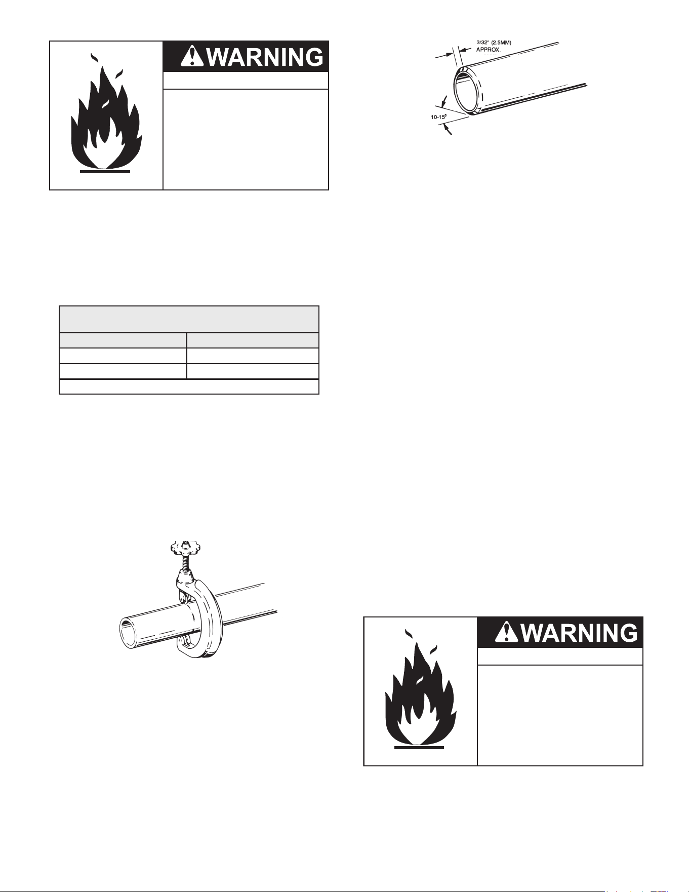
Fire Hazard
• Primers and cements are
extremely flamable, and must
not be stored or used near
heat or open flame.
• Also, use only in a well-venti-
lated area.
Applicators
Select a suitable pure bristle type paint brush. Use a proper
width brush or roller to apply the primer and cement. See
Table
6
. Speedy application of cement is important due to its fast
drying characteristics.
Important: A dauber type applicator should only be used on
pipe sizes 2” and below. For larger diameter pipe,
a brush or roller must be used.
Table 6. Recommended Brush* Size for Primer and
Cement Applications
Nominal Pipe (IPS) Size Brush Width
2 1.5” (3.8 cm)
3 1.5” - 2.5” (3.8 cm - 6.4 cm)
Use only natural bristle.
7. Making the Joint
A. Cutting
Pipe must be squarely cut to allow for the proper interfacing
of the pipe end and the tting socket bottom. This can be
accomplished with a miter box saw or wheel type cutter. Wheel
type cutters are not generally recommended for larger diameters
since they tend to are the corner of the pipe end. If this type of
cutter is used, the are on the end must be completely removed.
Note: Power saws should be specically designed to cut plastic
pipe.
Figure 19. Step A,Tube Cutter for Cutting Plastic Pipe
B. Deburring
Use a knife, plastic pipe deburring tool, or le to remove burrs
from the end of small diameter pipe. Be sure to remove all burrs
from around the inside as well as the outside of the pipe. A slight
chamfer (bevel) of about 10°-15° should be added to the end
to permit easier insertion of the pipe into the end of the tting.
Failure to chamfer the edge of the pipe may remove cement
from the tting socket, causing the joint to leak.
Figure 20. Step B, Removing Burrs from the End of the Pipe
C. Test dry t of the joint
Tapered tting sockets are designed so that an interfaced t
should occur when the pipe is inserted about 1/3 to 2/3 of the
way into the socket. Occasionally, when pipe tting dimensions
are at the tolerance extremes, it will be possible to fully insert
dry pipe to the bottom of the tting socket. When this happens,
a sucient quantity of cement must be applied to the joint to ll
the gap between the pipe and tting. The gap must be lled to
obtain a strong, leak-free joint.
D. Inspection, cleaning, priming
Visually inspect the inside of the pipe and tting sockets and
remove all dirt, grease or moisture with a clean dry rag. If
wiping fails to clean the surfaces, a chemical cleaner must be
used. Check for possible damage such as splits or cracks and
replace if necessary.
Depth-of-entry
Marking the depth of entry is a way to check if the pipe has
reached the bottom of the tting socket in Step F. Measure the
tting depth and mark this distance on the pipe O.D. You may
want to add several inches to the distance and make a second
mark as the primer and cement will most likely destroy your
rst one.
Apply primer to the surface of the pipe and tting socket with
a natural bristle brush. This process softens and prepares the
PVC or CPVC for the solvent cementing step. Move quickly and
without hesitation to the cementing procedure while the surfaces
are still wet with primer.
E. Application of solvent cement
• Apply solvent cement evenly and quickly around outside
of pipe at a width a little greater than the depth of the t-
ting socket.
• Apply a light coat of cement evenly around the inside of
the tting socket. Avoid puddling.
• Apply a second coat of cement to the pipe end.
Fire Hazard
• Cans of primer and cements
should be closed at all times
when not in use to prevent
evaporation of chemicals and
hardening of cement.
• They are also very flamable
and should be kept away from
heat or flame.
24
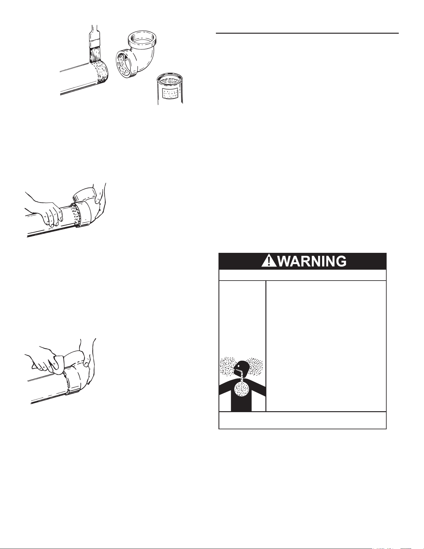
Figure 21. Setp E, Applying Solvent Cement
F. Joint Assembly
Working quickly, insert the pipe into the tting socket bottom and
give the pipe or tting a 1/4 turn to evenly distribute the cement.
Do not continue to rotate the pipe after it has hit the bottom of the
tting socket. A good joint will have sucient cement to make a
bead all the way around the outside of the tting hub. The tting
will have a tendency to slide back while the cement is still wet
so hold the joint together for about 15 seconds.
Figure 22. Step F, Assembling the Joint
G. Cleanup and joint movement
Remove all excess cement from around the pipe and tting with
a dry cotton rag. This must be done while the cement is still soft.
The joint should not be disturbed immediately after the
cementing procedure, and sucient time should be allowed for
proper curing of the joint. Exact drying time is dicult to predict
because it depends on variables such as temperature, humidity
and cement integrity. For more specic information, you should
contact your solvent cement manufacturer.
Figure 23. Step G, Cleaning Up the Joint
VENT PIPE ASSEMBLY
There are three parts of the vent pipe assembly that connect the
water heater exhaust (located on lower back side of water heater)
to inlet of the blower assembly (mounted on top of water heater) as
shown in
Figure 1
(page 7). These parts will need to be assembled
according to the instructions in
Vent Pipe Preparation
(page 23).
These PVC parts should be assembled with ASTM D-2564 grade
cement.
Assemble Vent Pipe Assemblies #1, #2 and #3 prior to cementing.
See
Figure 1
(page 7).
The preferred orientation of Vent Pipe Assembly #1 (Condensate
U-Assembly) is shown in Figure 16. However this assembly may
be rotated to a dierent orientation as needed for the specic
installation requirements. Note the rotational orientation of each
part by marking a line several inches long across the joints.The
long tube of Vent Pipe Assembly #2 should be approximately
vertical. If it is found that either of the two pieces of pipe in Vent
Pipe Assembly #2 are too long for proper t-up, then remove as little
material as possible to improve the t-up. Keep in mind that the pipes
will insert slightly further into the elbows when cement is applied as
it acts as a lubricating agent. The vertical distance from the bottom
of the Condensate U-Assembly to the oor that supports the water
heater should be approximately 0.25” (0.64 cm). See
Figure 25
(page
28). Disassemble the parts and cement back together using the
alignment marks. After the cement dries, attach the assembly to
the blower and the water heater exhaust using the supplied rubber
boots and hose clamps.
A condensate trap is incorporated in the bottom of this vent pipe
assembly. See
Condensate Drain Installation
(page 28)
for further
details.
Breathing Hazard - Carbon Monoxide Gas
•
Install vent system in accordance with codes.
•
Do not operate water heater if exposed to flooding
or water damage.
•
High altitude models should be installed at
elevations above 5,300 feet (1,615 m). For
operation above 10,100 feet (3,079 m), a high
altitude orifice must be installed.
•
Do not operate if soot buildup.
•
Do not obstruct water heater air intake with
insulating jacket.
•
Do not place chemical vapor emitting products
near water heater.
•
Gas and carbon monoxide detectors are available.
•
Never operate the heater unless it is vented to the
outdoors
and has
adequate
air supply
to avoid risks
of improper operation, fire, explosion or asphyxiation.
•
Analyze the entire vent system to make sure that
condensate will not become trapped in a section of
vent pipe and therefore reduce the open cross
sectional area of the vent.
Breathing carbon monoxide can cause brain damage or
death. Always read and understand instruction manual.
25
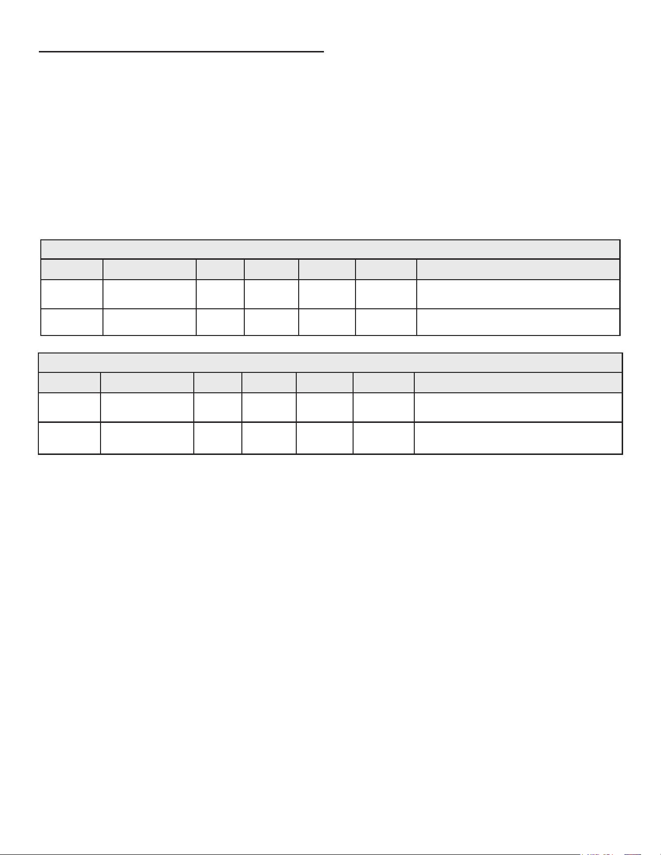
POLYPROPYLENE INSTALLATIONS
The water heater has been approved to be installed with
Polypropylene vent material as shown in
Table 7
and
Table 8
. The
approved application of single wall, non-exible, non-concentric
Polypropylene vent material is oered by two specic manufacturers
(Centrotherm ECO Systems and DuraVent Polypropylene). These
listed products must be installed by following the vent manufacturer’s
instructions. See
Table 5
(page 21) to determine the maximum pipe
length and number of elbows that can be used.
Insulation should not be used on Polypropylene venting materials.
The use of insulation will cause increased vent wall temperatures,
which could result in vent pipe failure.
Use only the adapters and vent system listed in
Table 7
and
Table
8
(page 26). DO NOT mix vent systems of different types or
manufacturers. Failure to comply could result in severe personal
injury, death, or substantial property damage.
Installations must comply with applicable national, state, and local
codes. For Canadian installation, Polypropylene vent must be listed
as a
ULC-S636
approved system. If Polypropylene vent is not required
by your local code, you may use either PVC or CPVC pipes for your
water heater that allows non-metallic venting material installations.
Polypropylene vent systems do not use cement to connect the pipe
and elbow sections but use a push together gasket seal method.
Do not attempt to connect Polypropylene with sealant cement. All
vent connections MUST be secured by the vent manufacturer’s joint
connector. The installer must use a specic vent starter adapter at
the ue connection. The adapter is supplied by the vent manufacturer
to adapt to its vent system.
In order to be in full compliance with
UL 1738
or
ULC-S636
and to meet
the requirements of the water heater manufacturer, you must use
the metal joint connector rings, available from the Polypropylene
vent manufacturer, to stien the joints of 2”, and 3” diameter pipes.
Table 7. M & G Duravent PolyPro
Nominal Pipe
Diameter
Flue Outlet Adapter
Adapter
Connector
Ring
Connector
90 Degree
Elbow
Vent Material Terminal(s)
2” 2PPS-AD PPS-PAC 2PPS-LB 2PPS-E90 2PPS
2PPS & 2PPS-BG for Exhaust;
2PPS-E90 & 2PPS-BG for Intake (Direct Vent only)
3” 3PPS-AD PPS-PAC 3PPS-LB 3PPS-E90 3PPS
3PPS & 3PPS-BG for Exhaust;
3PPS-E90 & 3PPS-BG for Intake (Direct Vent only)
Table 8. Centrotherm InnoFlue SW
Nominal Pipe
Diameter
Flue Outlet Adapter
Adapter
Connector
Ring
Connector
90 Degree
Elbow
Vent Material Terminal(s)
2”
ISAGL
0202
IAFC02 IANS02 ISELL0287 ISVL02
ISVL02 & IASPP02 for Exhaust;
ISELL0287 & IASPP02 for Intake (Direct Vent only)
3”
ISAGL
0303
IAFC03 IANS03 ISELL0387 ISVL03
ISVL03 & IASPP03 for Exhaust;
ISELL0387 & IASPP03 for Intake (Direct Vent only)
26
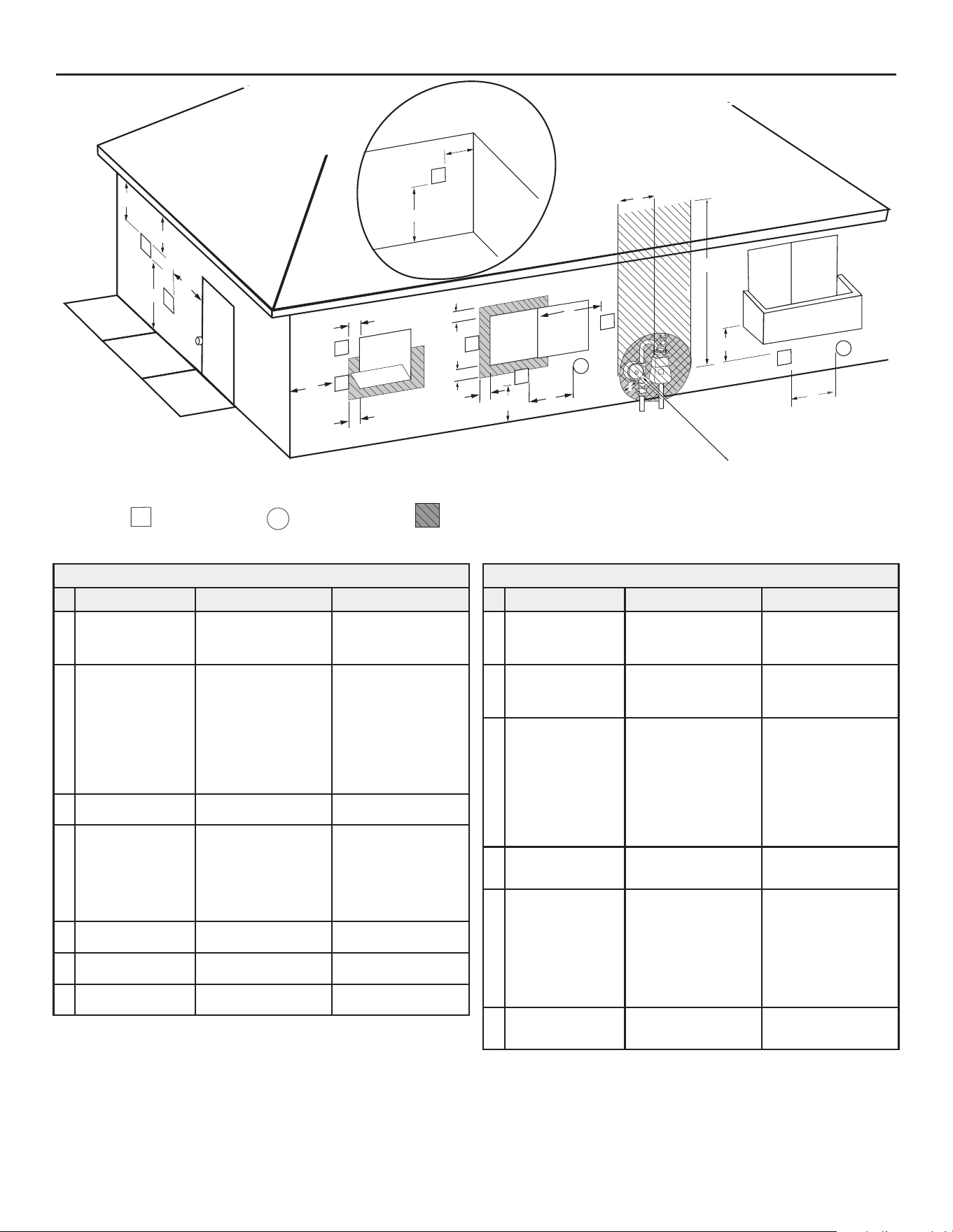
TERMINATION CLEARANCES OTHER THAN SIDEWALL DIRECT VENT
Fixed
Closed
Operable
Fixed
closed
Operable
B
V
V
V
V
V
V
V
V
C
B
B
X
A
M
K
Regulator vent outlet
In the event no
regulator is present,
H and I can be
disregarded
.
V
Legend:
= Vent terminal
X
= Air supply inlet
= Area where terminal is not permitted
B
B
J
F
X
B
L
E
D
Inside
corner detail
V
A
G
H
15 ft
I
Figure 24. Other than Direct Vent Using Outside Air
Termination Clearances for Sidewall Direct Vent
Type of Clearance
Canadian Installations
1
US Installations
2
A Clearance above
grade, veranda,
porch, deck or
balcony
12 inches (30 cm) 12 inches (30 cm)
B
Clearance to window
or door that may be
opened
• 6 in (15 cm) for
appliances ≤ 10,000
Btuh (3 kW)
• 12 in (30 cm) for
appliances > 10,000
Btuh (3 kW) and ≤
100,000 Btuh (30
kW),
• 36 in (91 cm) for ap-
pliances > 100,000
Btuh (30 kW)
• 4 feet (1.2 m) below
or to side of opening;
• 1 foot (30 cm) above
opening
C Clearance to perma-
nently closed window
6 inches (15 cm)* 6 inches (15 cm)*
D Vertical clearance
to ventilated sot
located above the
terminal within a
horizontal distance of
2 feet (61 cm) from
the center line of the
terminal
12 inches (30 cm) 12 inches (30 cm)
E Clearance to unventi-
lated sot
12 inches (30 cm) 12 inches (30 cm)
F Clearance to outside
corner
2 feet (60 cm)* 2 feet (60 cm)*
G Clearance to inside
corner
18 inches (45 cm)* 18 inches (45 cm)*
Termination Clearances for Sidewall Direct Vent
Type of Clearance
Canadian Installations
1
US Installations
2
H Clearance to each
side of center line ex-
tended above meter/
regulator assembly
3 ft (91 cm) within a
height 15 ft (4.6 m)
Clearance in accordance
with local installation
codes and the require-
ments of the gas supplier
I
Clearance to service
regulator vent outlet
3 ft (1.83 m)
Clearance in accordance
with local installation
codes and the require-
ments of the gas supplier
J
Clearance to a non
mechanical air supply
inlet into building or
combustion air inlet to
any other appliance
• 6 in (15 cm) for
appliances ≤ 10,000
Btuh (3 kW)
• 12 in (30 cm) for
appliances > 10,000
Btuh (3 kW) and ≤
100,000 Btuh (30
kW)
• 36 in (91 cm) for
appliances >100,000
Btuh (30 kW)
• 4 feet (1.2 m) below
or to side of opening;
• 1 foot (30 cm) above
opening
K Clearance to a
mechanical air supply
inlet
6 feet (1.83 m)
3 feet (91 cm) above
if within 10 feet (3 m)
horizontally
L
Clearance above
paved sidewalk or
paved driveway
located on public
property
7 feet (2.13 m)†
7 ft (2.13 m) for me-
chanical draft systems
(Category I appliances);
vents for Category II and
IV appliances cannot
be located above public
walkways or other areas
where condensate or va-
por can cause a nuisance
or hazard
M Clearance under
veranda, porch, deck,
or balcony
12 inches (30 cm) ‡ 12 inches (30 cm) ‡
1 In accordance with the current
CSA B149.1, Natural Gas and Propane Installation Code
.
2 In accordance with the current
ANSI Z223.1/NFPA 54, National Fuel Gas Code
.
† A vent shall not terminate directly above a sidewalk or paved driveway that is
located between two single family dwellings and serves both dwellings where it may
cause hazardous frost or ice accumulations on adjacent property surfaces.
‡ Permitted only if veranda, porch, deck, or balcony is fully open on a minimum of
two sides beneath the oor.
27
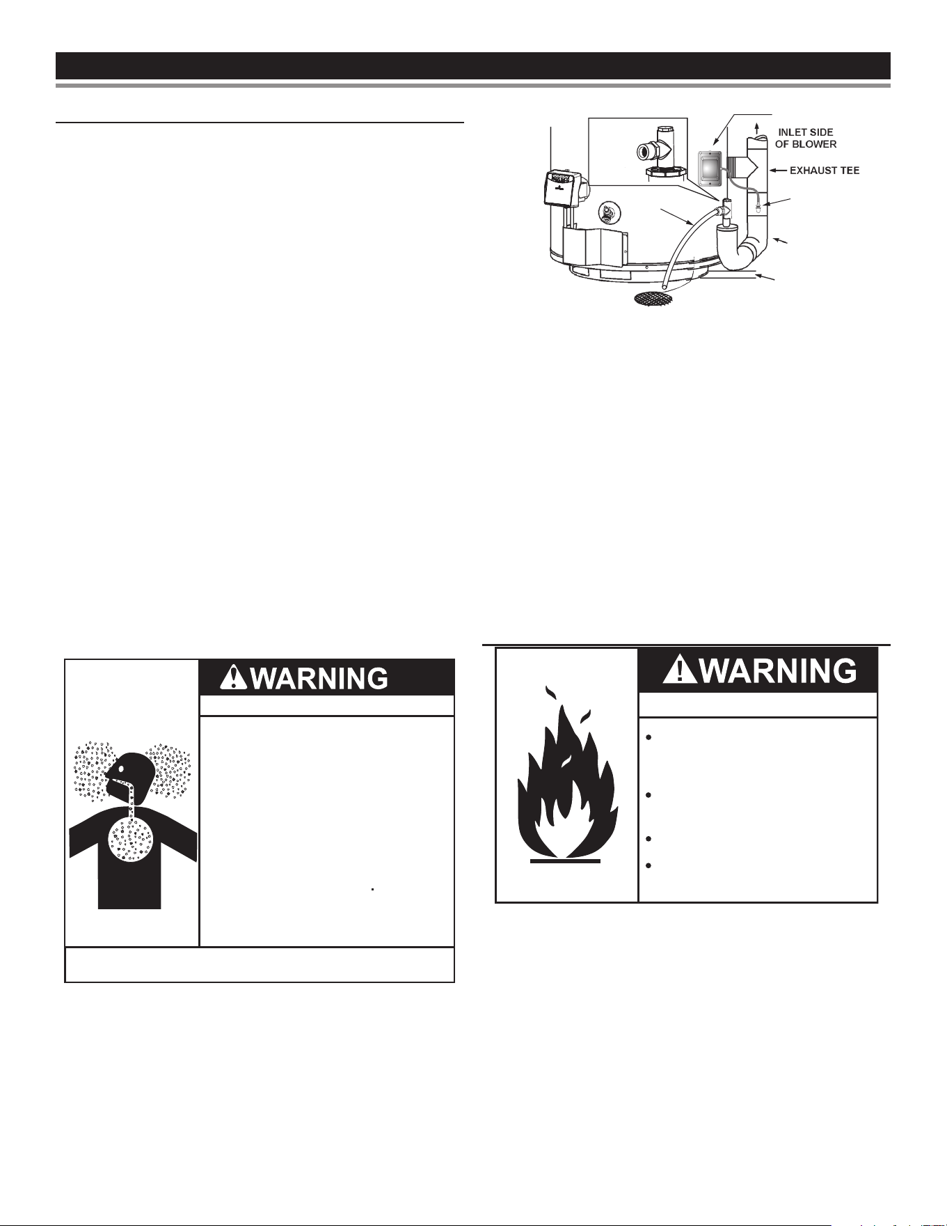
WATER HEATER INSTALLATIONWATER HEATER INSTALLATION
CONDENSATE DRAIN INSTALLATION
This water heater is a condensing unit and requires a drain to
be located in close proximity to allow condensate to drain safely.
One hose from blower housing and two exible hoses from blower
outlet adaptor run to barb ttings on vent pipe assembly #2. Hose
is clamped by rubber clips and exible hoses by a clamp on jacket
top cover. See
Figure 15
(page 21). Condensate drains from the
unit at the exhaust tee located at the bottom of the unit. See
Figure
25
. Condensate from this water heater is mildly acidic. Please note
that some local codes require that condensate is treated by using a
pH neutralizing lter prior to disposal.
Note: It is important that the eld supplied drain lines beyond the
1/2” adaptor of vent pipe assembly #1 should be installed
continuously tilted downward toward an appropriate drain.
See
Figure 25
. If these instructions are not followed or
if condensate drain line is blocked, water will spill from
condensate trap. Do not block the holes in the hex plug on
top of a small tee in vent pipe assembly #1. As with every
water heater installation, a drain pan should be used to
prevent water damage to surrounding area. If necessary,
a condensate pump with an incorporated reservoir may
be used to pump water to an appropriate drain. To avoid
condensate spillage, select a pump with an overow
switch.
Caution must be used to ensure that drain is free and clear of debris
and will not allow backow through the condensate drain line.
Consideration must be given to avoid freezing of the condensate
lines which could result in excessive build up of condensate inside
the water heater. Waterproof heat tape may be required to prevent
freezing of condensate lines. Please ensure that the outlet of
condensate drain does not create a slippery condition which could
lead to personal injury. Care should be taken to ensure there is no
kink or twist in any condensate hose. If a VAA is not installed, the
unused barb tting in vent pipe assembly #2 should be plugged using
one of the break-away plugs.
Breathing Hazard
Breathing carbon monoxide can cause brain damage or
death. Always read and understand instruction manual.
•
Condensate lines must be free and clear of debris
and must not allow back flow through the hose.
The condensate lines must be able to flow freely
to
an appropriate drain.
•
Do NOT elevate any portion of the field supplied
drain line beyond the 1/2” adaptor above the
adaptor line beyond the 1/2” adaptor above the
adaptor. This must be true for the entire length
of
the drain line, including the exit into an
appropriate drain
.
•
Do NOT block the holes in the hex plug of the vent
pipe assembly.
•
Do NOT allow condensate lines to become crimped
closed.
•
Analyze entire vent system to make sure that
condensate will not become trapped in a section of
vent pipe and therefore reduce open cross-sectional
area of the vent.
The condensate trap may be primed by lling the Condensate
U-Assembly with tap water while the water heater is not operating.
The system is fully primed when the water level reaches the adaptor
connected into the Tee. In most installations the water heater will
self-prime the condensate trap during the rst full heat-up cycle. If
a sound of air bubbling through water (gurgling) is heard while the
blower is operating after the rst heat-up cycle, then turn the unit o
and contact your plumber or service representative.
If these instructions are not followed, the condensate build-up will
block the exhaust outlet, which will cause improper operation.
CONDENSATE
U-ASSEMBLY,
AKA. VENT PIPE
ASSEMBLY #1
*NO PORTION OF THE FIELD SUPPLIED DRAIN LINE BEYOND
THE 1/2" ADAPTOR M AY BE ELEVATED HIGHER THAN THE
ADAPTOR. THIS MUST BE TRUE FOR THE ENTIRE LENGTH
OF DRAIN LINE INCLUDING EXIT INTO AN APPROPRIATE DRAIN.
APPROXIMATELY
0.25" (6.35 mm)
PRESSURE
TAP
PRESSURE SWITCH COVER
Do NOT
block or
plug any
hole in this
hex plug.
DRAIN LINE
Figure 25. Condensate Drain Configuration
Condensate is likely to form in the venting system attached to
this water heater. The vent pipe should be sloped downward
away from the blower assembly (not less than 1/8” (3.2 mm)
nor greater than 1/2” (12.7 mm) per foot (30 cm) maximum). If
the vent piping is vented level or sloped upwards away from
the blower assembly, then adequate means for draining and
disposing of the condensate needs to be made by the installer.
Two 3/8” condensate hoses should be connected to the built-in
drain ports of blower outlet adaptor. The unused barb tting
on vent pipe assembly #2 should be plugged with one of the
break-away plugs. See
Figure 15
(page 21).
Condensate neutralizer kits are available. Contact your distributor
or Service Agency.
GAS PIPING
Fire and Explosion Hazard
Do not use water heater with any
gas other than the gas shown on
the rating plate.
Excessive pressure to gas control
valve can cause serious injury or death
Turn off gas lines during installation.
Contact qualified installer or
service agency.
Make sure the gas supplied is the same type listed on the model
rating plate. The inlet gas pressure must not exceed 14 inch water
column (3.5 kPa) for natural and propane gas (L.P.). The minimum
inlet gas pressure shown on the rating plate is that which will permit
ring at rated input.
All gas piping must comply with local codes and ordinances or with
the
National Fuel Gas Code (ANSI Z223.1/ NFPA-54)
. Copper or brass tubing
and ttings (except tin lined copper tubing) should not be used.
If the gas control valve is subjected to pressures exceeding 1/2 psi
(3.5 kPa), the damage to the gas control valve could result in a re
or explosion from leaking gas.
If the main gas line Shutto serving all gas appliances is used, also
turn “o” the gas at each appliance. Leave all gas appliances shut
“o” until the water heater installation is complete.
28
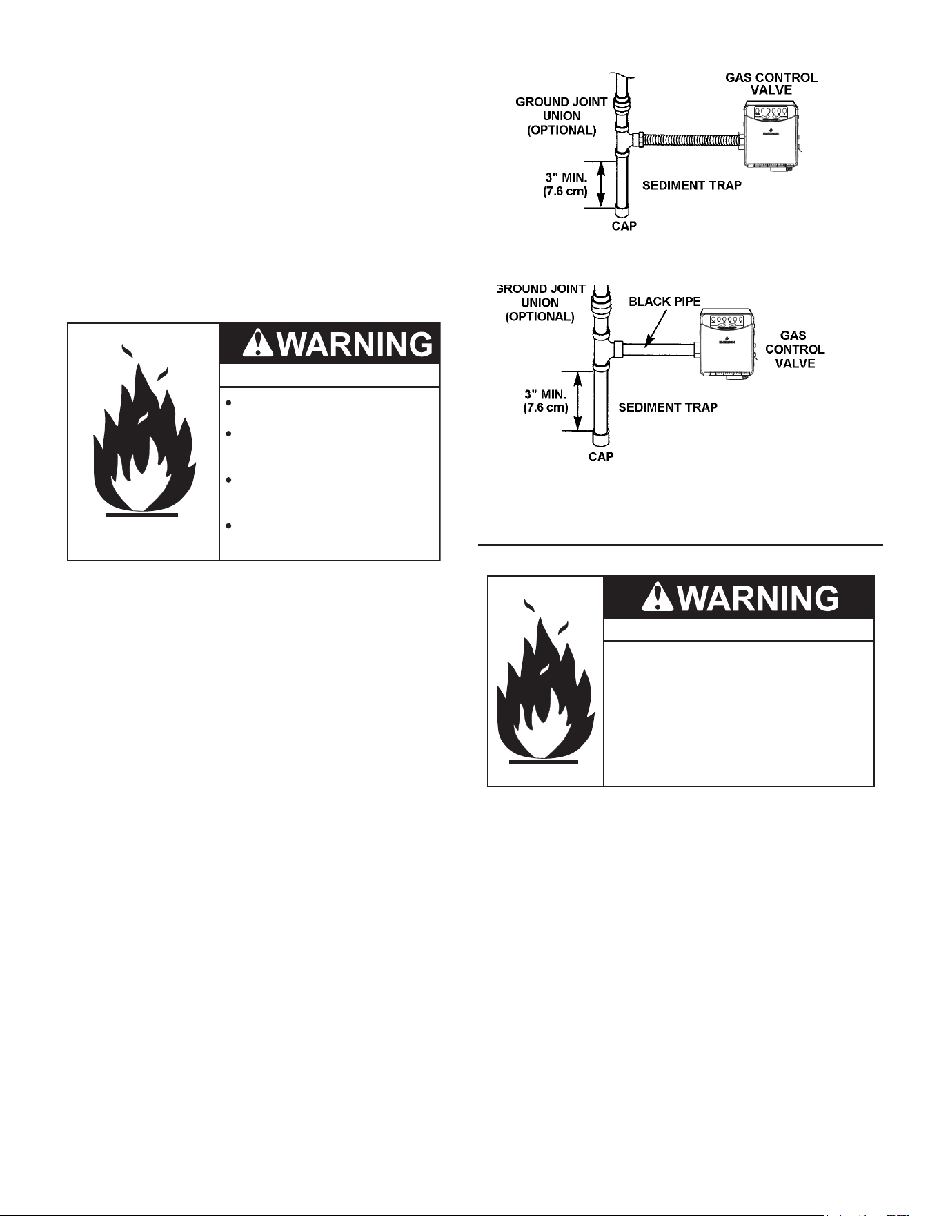
A gas line of sucient size must be run to the water heater. Consult
the current edition of
National Fuel Gas Code (ANSI Z223.1/NFPA 54)
and
your gas supplier concerning pipe size.
There must be:
• A readily accessible manual shutto valve in the gas supply line
serving the water heater, and
• A sediment trap ahead of gas control valve to help prevent dirt
and foreign materials from entering the gas control valve.
• A exible gas connector or a ground joint union between the
shutto valve and control valve to permit servicing of the unit.
Be sure to check all the gas piping for leaks before lighting the water
heater. Use a soapy water solution, not a match or open ame. Rinse
o soapy solution and wipe dry.
Fire and Explosion Hazard
Leak test gas connections
before placing the water heater in
operation.
Disconnect gas piping at main
gas shutoff valve before leak
testing.
Install sediment trap in accordance
with NFPA 54 or CAN/CSA B149.1.
Use joint compound or Teflon tape
compatible with propane gas.
Use pipe joint compound or teon tape marked as being resistant
to the action of petroleum [Propane (L.P.)] gases.
The appliance and its gas connection must be leak tested before
placing the appliance in operation.
The appliance and its individual Shutto valve should be disconnected
from the gas supply piping system during any pressure testing of
that system at test pressures in excess of 1/2 pound per square inch
(3.5 kPa). It should be isolated from the gas supply piping system
by closing its individual manual Shutto valve during any pressure
testing of the gas supply piping system at test pressures equal to
or less than 1/2 pound per square inch (3.5 kPa).
Connecting gas piping to the gas control valve of water heater can be
accomplished by either of two methods shown in Figures 12 and 13.
Figure 26. Gas Piping with Flexible Connector
Figure 27. Gas Piping with All Black Iron Pipe to Gas Control.
SEDIMENT TRAPS
Fire and Explosion Hazard
• Contaminant in gas lines can
cause fire or explosion.
• Clean all gas piping before
installation.
• Install drip leg in accordance with
NFPA 54 or CAN/CSA-B149.1.
A sediment trap should be installed as close to the inlet of the water
heater as practical at the time of water heater installation. The
sediment trap should be either a tee tting with a capped nipple in
the bottom outlet or other device recognized as an eective sediment
trap. If a tee tting is used, it should be installed in conformance
with one of the methods of installation shown in Figures 12 and 13.
Contaminants in the gas lines may cause improper operation of the
gas control valve that may result in re or explosion. Before attaching
the gas line be sure that all gas pipe is clean on the inside. To trap
any dirt or foreign material in the gas supply line, a sediment trap
must be incorporated in the piping. The sediment trap must be readily
accessible. Install in accordance with the “Gas Piping” section. See
the current edition of the
National Fuel Gas Code (ANSI Z223.1/NFPA 54)
.
29
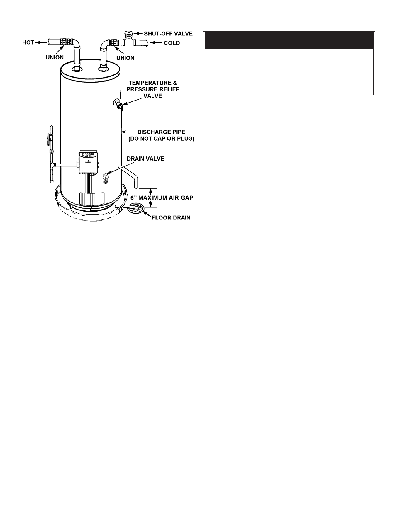
Figure 28. Typical Piping Configuration
FILLING THE WATER HEATER
Property Damage Hazard
To avoid water heater damage, fill tank with water
before operating.
CAUTION
Never use this water heater unless it is completely full of water.
To prevent damage to the tank, the tank must be lled with water.
Water must ow from the hot water faucet before turning “ON” gas
to the water heater.
To ll the water heater with water:
1. Close the water heater drain valve by turning handle to the right
(clockwise). The drain valve is on the lower front of water heater.
2. Open the cold water supply valve to the water heater.
Note: The cold water supply valve must be left open when the
water heater is in use.
3. To insure complete lling of the tank, allow air to exit by opening
nearest hot water faucet. Allow water to run until a constant ow
is obtained. This will let air out of the water heater and the piping.
4. Check all water piping and connections for leaks. Repair as
needed.
30
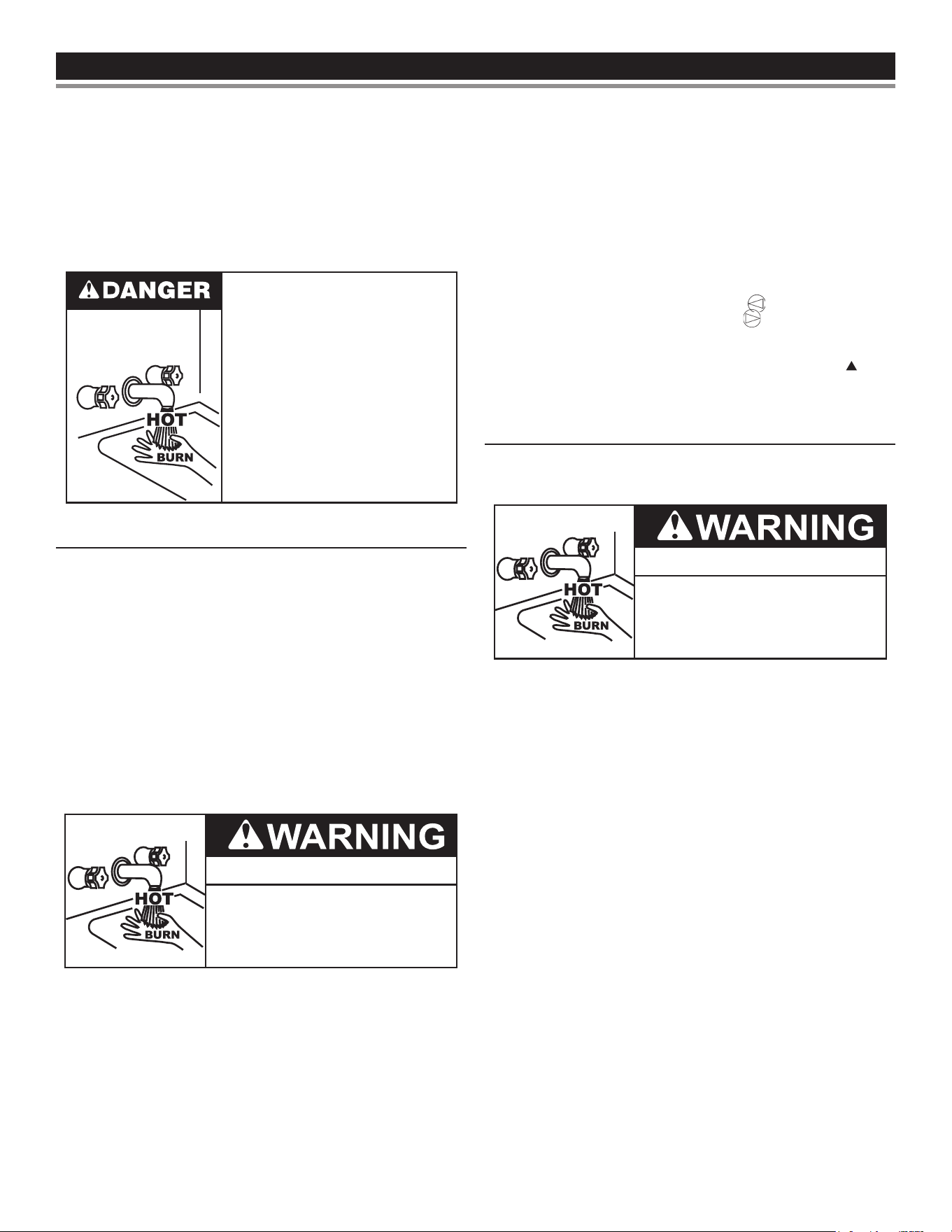
TEMPERATURE REGULATIONTEMPERATURE REGULATION
It is recommended that lower water temperatures be used to avoid
the risk of scalding. It is further recommended, in all cases, that the
water temperature be set for the lowest temperature which satises
your hot water needs. This will also provide the most energy ecient
operation of the water heater.
Short repeated heating cycles caused by small hot water uses can
cause temperatures at the point of use to exceed the thermostat
setting by up to 20°F (11°C). If you experience this type of use you
should consider using lower temperature settings to reduce scald
hazards.
Water temperature over 125°F (52°C)
can cause severe burns instantly
resulting in severe injury or death.
Children, the elderly and the physically
or mentally disabled are at highest risk
for scald injury.
Feel water before bathing or showering.
Temperature limiting devices such as
point-of-use mixing valves must be
installed when required by codes and to
ensure safe temperatures at fixtures.
HOT WATER CAN SCALD
Water heaters are intended to produce hot water. Water heated to a
temperature which will satisfy space heating, clothes washing, dish
washing, and other sanitizing needs can scald and permanently injure
you upon contact. Some people are more likely to be permanently
injured by hot water than others. These include the elderly, children,
the inrm, or physically/mentally handicapped. If anyone using hot
water from this heater ts into one of these groups or if there is a
local code or state law requiring a certain temperature water at the
hot water tap, then you must take special precautions.
In addition to using the lowest possible temperature setting that
satises your hot water needs, a means such as a mixing valve,
should be used at the hot water taps used by these people or
at the water heater.
Check State and/or local codes for mixing valve requirements and
installation practices.
Burn Hazard
To reduce the risk of unusually hot
water reaching the fixtures in the
house, install thermostatic mixing
valves at each point of use.
Mixing valves are available at plumbing supply or hardware stores.
See
Figure 2
(page 8). Follow manufacturer’s instructions for
installation of the valves. Before changing the factory setting on the
thermostat, in this manual, see
Figure 29
.
Never allow small children to use a hot water tap, or to draw their own
bath water. Never leave a child or handicapped person unattended
in a bathtub or shower.
The water heater should be located in an area where the general
public does not have access. If a suitable area is not available, a
cover should be installed over the thermostat to prevent tampering.
The water temperature setting was factory set at the lowest
temperature; Pressing the “COOLER” button decreases
temperature and pressing the “HOTTER” button increases the
temperature.
Setting water heater temperature at 120°F (49°C) (Approx. “ ” mark
on temperature setting of gas valve) will reduce risks of scalds. Some
states or local codes require settings at specic lower temperatures.
CHANGING THE TEMPERATURE SETTING
To avoid any unintentional changes in water temperature settings, the
control has a tamper resistant feature for changing the temperature
setting. To change the temperature setting follow these instructions:
Burn Hazard
If you choose a higher temperature setting,
install thermostatic mixing valves at each
point-of-use to help avoid scalding.
1. “Wake Up” the temperature indicators by holding down both
“COOLER” and “HOTTER” temperature adjustment buttons at
the same time for one second. See
Figure 29
. One or two of the
temperature indicators will light up. These indicators will only
remain on for 30 seconds if no further buttons are pressed. After
30 seconds the control will go back to “Sleep” mode.
2. Release both of the temperature adjustment buttons.
A. To decrease the temperature press and release the
“COOLER” button until the desired setting is reached.
B. To increase the temperature press and release the
“HOTTER” button until the desired setting is reached.
Note: Holding down the button will not continue to lower or raise
the temperature setting. The button must be pressed and
released for each temperature change desired.
Should overheating occur or the gas supply fail to shutto, turn o
the manual gas control valve to the appliance.
31
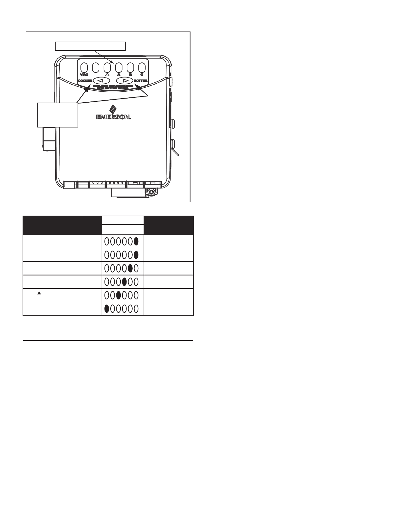
Temperature Indicators
Temperature
Adjustment
Buttons
Figure 29. Adjusting the Thermostat
Water Temperature
Display
Time to Produce
2nd & 3rd Degree
Burns on Adult Skin B C D E F
C-Flashing = approx. 160°F (71°C)
About 1/2 second
C = approx. 150°F (66°C)
About 1-1/2 seconds
B = approx. 140°F (60°C)
Less than 5 seconds
A = approx. 130°F (54°C)
About 30 seconds
= approx. 120°F (49°C)
More than 5 minutes
VAC = approx. 80°F (27°C)
- - - - - - - - - - - - - -
HIGH WATER TEMPERATURE SHUT OFF SYSTEM
This water heater is equipped with a manually resettable type high
limit (Energy Cuto) sensor. The high limit switch interrupts the main
burner gas ow should the water temperature reach 195°F (91°C).
The high limit can be manually reset when the water temperature
drops below 140°F (60°C). After cooling the tank temperature, turn
o the water heater for at least 10 seconds by using the switch on
top of the unit. Turn on the water heater. If this fails to correct the
problem, contact your plumber or service representative.
32
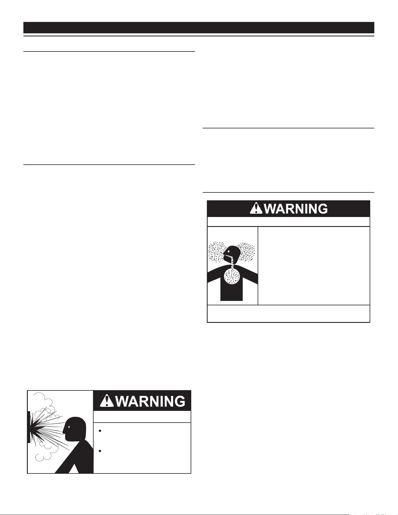
START UPSTART UP
START UP CONDITIONS
SMOKE/ODOR
It is not uncommon to experience a small amount of smoke and odor
during the initial start-up. This is due to burning o of oil from metal
parts, and will disappear in a short while.
STRANGE SOUNDS
Possible noises due to expansion and contraction of some metal
parts during periods of heat-up and cool-down do not necessarily
represent harmful or dangerous conditions.
Condensation causes sizzling and popping within the burner area
during heating and cooling periods and should be considered normal.
See
Condensate Drain Installation
(page 28) in this manual.
OPERATIONAL CONDITIONS
SMELLY WATER
In each water heater there is installed at least one anode rod for
corrosion protection of the tank. Certain water conditions will cause a
reaction between this rod and the water. The most common complaint
associated with the anode rod is one of a “rotten egg smell” in the hot
water. The smell is a result of four factors which must all be present
for the odor to develop:
A. A concentration of sulfate in the supply water.
B. Little or no dissolved oxygen in the water.
C. A sulfate reducing bacteria which has accumulated within the
water heater (this harmless bacteria is nontoxic to humans).
D. An excess of active hydrogen in the tank. This is caused by the
corrosion protective action of the anode.
Smelly water may be eliminated or reduced in some water heater
models by replacing the anode(s) with one of less active material,
and then chlorinating the water heater tank and all water lines.
Contact the local water heater supplier or service agency for
further information concerning an Anode Replacement Kit and this
chlorination treatment.
If the smelly water persists after the anode replacement and
chlorination treatment, we can only suggest that chlorination or
aeration of the water supply be considered to eliminate the water
problem.
Do not remove the anode leaving the tank unprotected. By doing
so, all warranty on the water heater tank is voided.
AIR IN HOT WATER FAUCETS
Explosion Hazard
Flammable hydrogen gases
may be present.
Keep all ignition sources away
from faucet when turning on
hot water.
HYDROGEN GAS: Hydrogen gas can be produced in a hot water
system that has not been used for a long period of time (generally
two weeks or more). Hydrogen gas is extremely ammable and
explosive. To prevent the possibility of injury under these conditions,
we recommend the hot water faucet, located farthest away, be
opened for several minutes before any electrical appliances
which are connected to the hot water system are used (such as a
dishwasher or washing machine). If hydrogen gas is present, there
will probably be an unusual sound similar to air escaping through the
pipe as the hot water faucet is opened. There must be no smoking
or open ame near the faucet at the time it is open.
HIGH WATER TEMPERATURE SHUTOFF SYSTEM
A high temperature limit switch or ECO (Energy Cut O) in the tank
is used to shut o the unit if the water temperature exceeds 195°F
(91°C). The ECO is a single use switch and requires complete
replacement of the entire gas control valve/thermostat. If the ECO
should acuate, the water heater cannot be used until the gas control
valve/thermostat is replaced by a qualied service agent. Contact the
local water heater supplier or service agency for service information.
HIGH ALTITUDE INSTALLATION
Breathing carbon monoxide can cause brain damage or death.
Always read and understand the instruction manual.
● High altitude models should be
installed at elevations above 5,300 feet
(1,615 m). For operation above 10,000
feet (3,079 m), a high-altitude orifice
must be installed.
● Contact a qualified installer or service
agency.
Breathing Hazard - Carbon Monoxide Gas
This heater is approved for operation up to 5,300 feet (1,615 m)
without alteration. High altitude models are available from the factory
for elevations between 5,300 feet (1,615 m) and 10,100 feet (3,079
m). For elevations above 10,100 feet (3,079 m) the input rating
should be reduced at the rate of 4 percent for each 1,000 feet (305
m) above sea level which requires replacement of the burner orice
in accordance with
National Fuel Gas Code (ANSI Z223.1/NFPA 54)
. Contact
your local gas supplier for further information.
Failre to replace standard orice with a high altitude orice when
installed above 10,100 feet (3,079 m) could result in improper and
inecient operation of the appliance, producing carbon monoxide
gas in excess of safe limits, which could result in serious injury or
death. Contact your gas supplier for any specic changes which may
be required in your area.
33
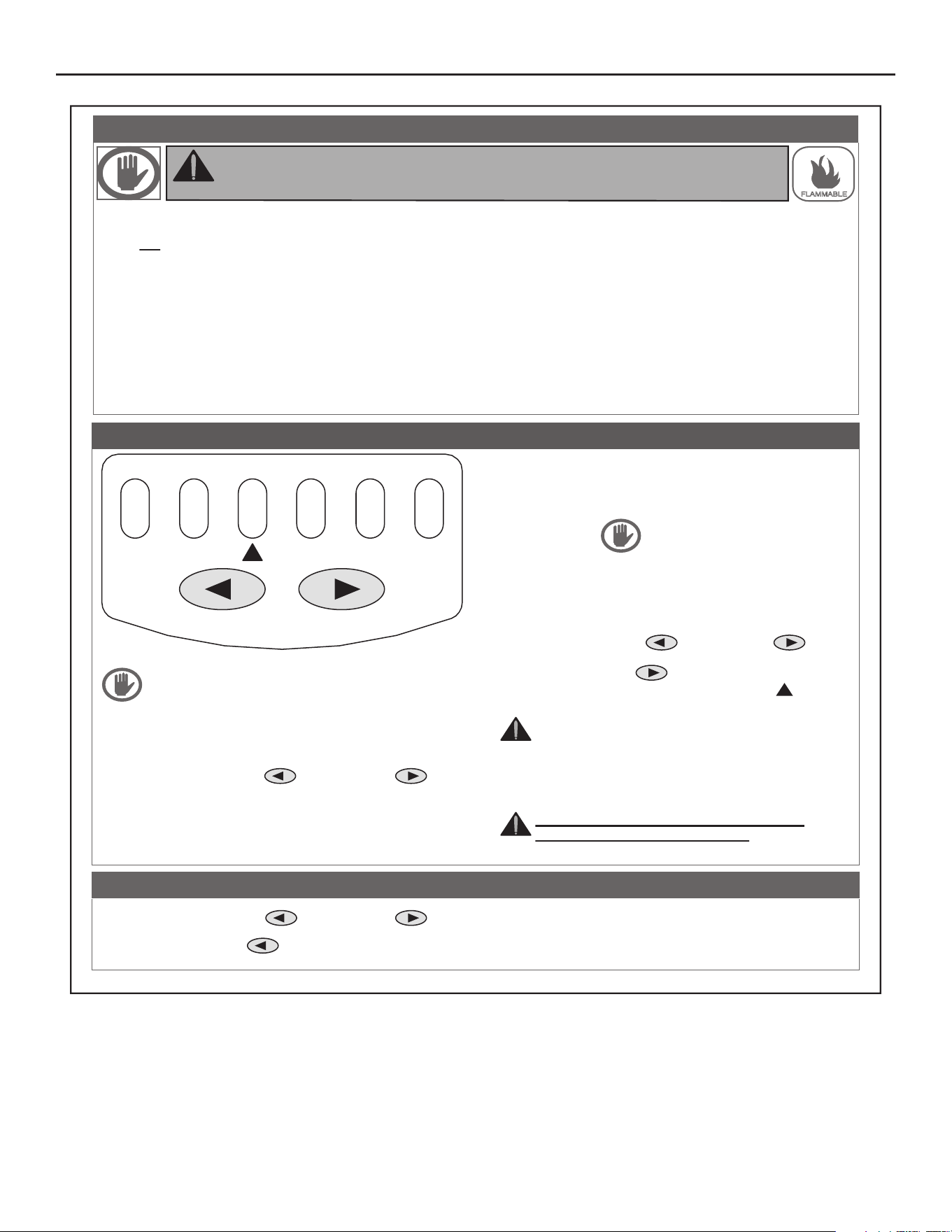
LIGHTING AND OPERATION LABEL
1. Set the thermostat to the lowest setting by first
pressing the COOLER and HOTTER
buttons together and holding for 1 second. Then
press the COOLER button until the VAC
indicator light appears.
2. Set the ON/OFF switch on the control box to the
“OFF” position.
3. Turn off all electrical power to the appliance if
service is to be performed.
TO TURN OFF GAS TO APPLIANCE
ELBAMMALF
:GNINRAW
ro erif a ,yltcaxe snoitcurtsni eseht wollof ton od uoy fI
yrujni lanosrep ,egamad ytreporp gnisuac tluser yam noisolpxe
.efil fo ssol ro
A. This appliance does not have a pilot. It is equipped with
an ignition device which automatically lights the burner.
Do not try to light the burner by hand.
B. BEFORE OPERATING smell all around the appliance
area for gas. Be sure to smell next to the floor because
gas is heavier than air and will settle to the floor.
“WHAT TO DO IF YOU SMELL GAS”
● Do not try to light the appliance
● Do not touch any electrical switch; do not use any
telephone in your building.
● Immediately call your gas supplier from a
neighbor’s phone. Follow the gas supplier’s
instructions.
● If you cannot reach your gas supplier, call the fire
department.
C. Use only your hand to push in the control buttons.
Never use tools. If the control buttons will not push in,
don’t try to repair them, call a qualified service
technician. Force or attempted repair may result in
fire or explosion.
D. Do not use this appliance if any part has been under
water. Immediately contact a qualified installer or
service agency to replace a flooded water heater.
Do not attempt to repair the service unit. It must be
replaced.
FOR YOUR SAFETY READ BEFORE LIGHTING
1. STOP! Read the safety information above on
this label.
2. Set the ON/OFF switch on the control box to the
“ON” position.
3. Set the thermostat to the lowest setting by first
pressing the COOLER and HOTTER
buttons together and holding for 1 second. Then
press the COOLER button until the VAC indicator
light appears.
4. Set the ON/OFF switch on the control box to the
“OFF” position.
5. This appliance is equipped with a device which
automatically lights the burner.
DO NOT TRY TO LIGHT THE BURNER BY HAND.
6. Wait five (5) minutes to clear out any gas. If you
then smell gas , STOP! Follow “B” in the safety
information above this label. If you don’t
smell gas go to the next step.
7. Turn on all electrical power to the appliance.
8. Set the ON/OFF switch on the control box to the
“ON” position.
9. Set the thermostat to the desired setting by first
setting the COOLER and HOTTER
buttons together and holding for 1 second. Then
press the HOTTER button.
10.WATER TEMPERATURE ADJUSTMENT is
approximately 120°F.
CAUTION: Hotter water increases the risk of
scald injury. Consult the instruction manual
before changing temperature.
11. If the appliance will not operate, follow the
instructions “TO TURN OFF GAS APPLIANCE” and
call your technician or gas supplier.
WARNING: TURN OFF ALL ELECTRIC
POWER BEFORE SERVICING.
OPERATING INSTRUCTIONS
VAC
COOLER
SCALDING RISK INCREASES
WITH HOTTER WATER
HOTTER
ABC
34
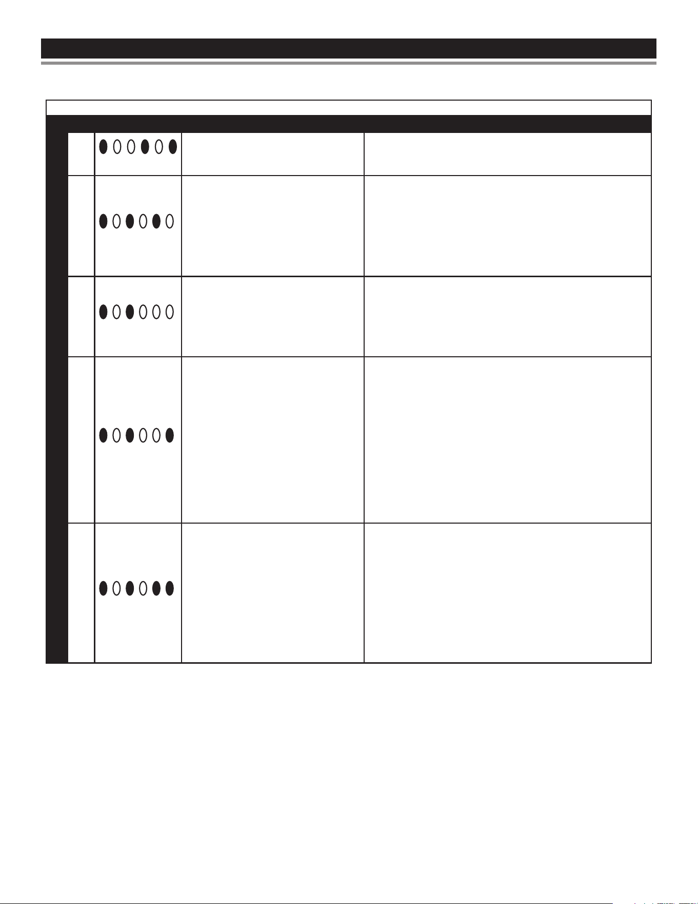
TROUBLESHOOTING GUIDELINESTROUBLESHOOTING GUIDELINES
Please check guidelines below. For your safety, water heater service
should be performed only by a qualied service technician.
Read the GENERAL SAFETY INFORMATION section rst.
INTELLI-VENT TROUBLESHOOTING CHART - USER CONTROL
LED Status
Problem 1. Solution
WATER HEATER CONTROL
1
VAC ▲ A B C
Inadequate or no earth ground.
1. Ensure the wall outlet (power supply) is properly grounded.
2. Ensure all ground connections/wires on the water heater
are securely connected.
2
VAC ▲ A B C
High resistance to earth ground or
reversed polarity in the 120 VAC power
supply.
1. Ensure that the water heater is securely connected to earth
ground.
2. Ensure that the wall outlet/power supply is properly wired.
Also, ensure that internal 120 VAC wiring connections and
the wiring harness have no reversed wires. 120 VAC “hot”
wire must connect to the on/o switch.
3
VAC ▲ A B C
Pressure switch circuit remaining
closed for more than 5 seconds after
heating cycle begins.
Blower may not start in this condition.
1. Ensure air pressure switch circuit wiring is correct and the
air pressure switch is not jumpered.
2. Replace the air pressure switch.
4
VAC ▲ A B C
Pressure switch circuit remains open
longer than 5 seconds after the blower
is energized.
Blower may run continuously in this
condition.
1. Ensure the air pressure switch sensing tube is properly
connected at both ends and is not kinked or damaged.
2. Ensure the correct size of vent and intake air pipe (direct
vent products) was used per the installation instructions in
the manual that came with the water heater.
3. Ensure maximum number of elbows or maximum equivalent
feet of vent or intake air pipe have not been exceeded per
the installation instructions in the manual that came with the
water heater.
4. Ensure there are no obstructions in the vent or intake air
pipe.
5. Ensure there are no obstructions in in unit’s condensate
trap and drain.
5
VAC ▲ A B C
Open igniter circuit.
1. Check wiring to the hot surface igniter assembly - replace
igniter assembly if wiring is damaged or worn.
2. Check resistance of the igniter at igniter assembly plug -
should be between 11 and 18 ohms at room temperature
(77° F at plug end) - replace igniter if open or shorted.
3. Check igniter assembly plug and the socket on the gas
control valve/thermostat for good connection. Replace
igniter assembly if the plug is worn or damaged.
4. Replace the gas control valve/thermostat if the igniter
assembly socket on the bottom of the control is worn or
damaged.
35
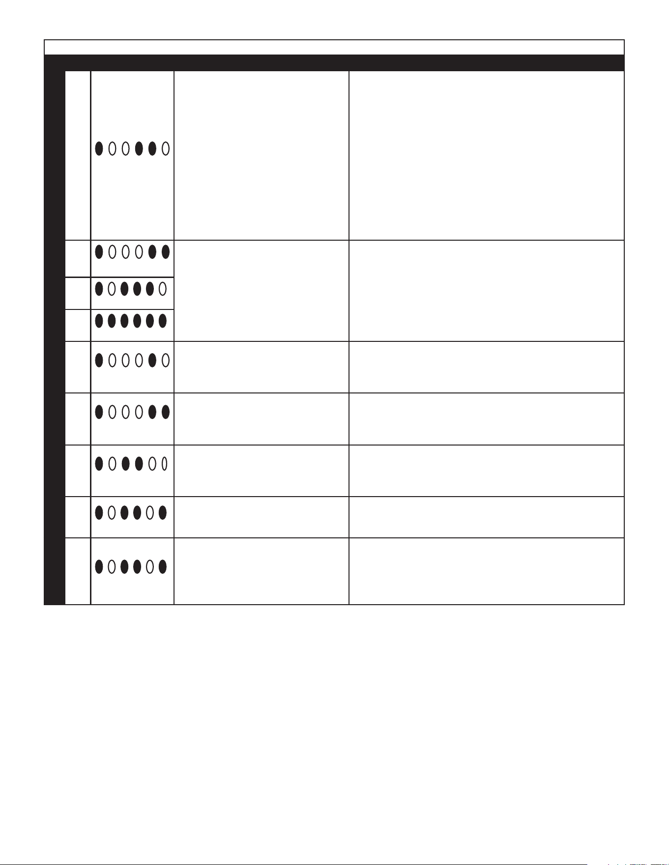
INTELLI-VENT TROUBLESHOOTING CHART - USER CONTROL
LED Status
Problem 1. Solution
WATER HEATER CONTROL
6
VAC ▲ A B C
Ignition/ame failure.
The gas control valve/thermostat has
reached the maximum number of retries
(3) for ignition and is currently locked
out for one hour.
Cycle the power to the water heater o
and on to reset.
1. Ensure ame sensor is making good contact with the burner
ame and ensure ame is steady. Also ensure supply and
manifold gas pressures are within the requirements in the
installation manual.
2. Gas supply is turned o - pressure is too low. For low gas
pressure, consult with your gas utility.
3. Ensure the ame sensor is clean - use ne steel wool to
clean the ame sensor.
4. Check igniter assembly plug and the socket on the bottom
of the gas control valve/thermostat for good connection.
Replace igniter assembly if the plug is worn or damaged.
Replace the gas control valve/thermostat if socket is worn
or damaged.
5. Replace igniter assembly.
7
VAC ▲ A B C
Self diagnostic check has detected
a problem with the gas valve driver
circuit, internal microprocessor, or other
internal circuits.
1. Turn the power o for 10-20 seconds then on again to clear
these error codes.
2. If any of these error codes persist or cannot be cleared -
replace the gas control valve/thermostat.
8
VAC ▲ A B C
9
VAC ▲ A B C
10
VAC ▲ A B C
Flame signal sensed out of proper
sequence.
1. Turn the power o for 10-20 seconds then on again to clear
these error codes.
2. Replace the gas control valve/thermostat if this error code
persists.
11
▲ B C D E F
Water in the tank has exceeded the
maximum allowable temperature,
activating the ECO (energy cut o).
1. Turn the power o for 10-20 seconds then on again to clear
these error codes.
2. Replace the gas control valve/thermostat if the error code
persists.
12
VAC ▲ A B C
One or both of the temperature adjust
buttons are stuck.
1. Press and release both temperature adjust buttons several
times - cycle water heater power o and on.
2. Replace the gas control valve/thermostat if the error code
persists.
13
VAC ▲ A B C
The self diagnostic test has detected the
water temperature sensor (thermistor)
is either open or shorted.
1. Turn the power o for 10-20 seconds then on again to clear
these error codes.
2. Replace the temperature probe if the error code persists.
14
VAC ▲ A B C
Weak ame current.
1. Low supply voltage to the water heater. Check and repair.
2. Ensure ame sensor is making good contact with burner
ame and ensure ame is steady.
3. Ensure the ame sensor is clean - use ultra ne steel wool
or Scotch-Brite™ pad to clean the ame sensor.
36
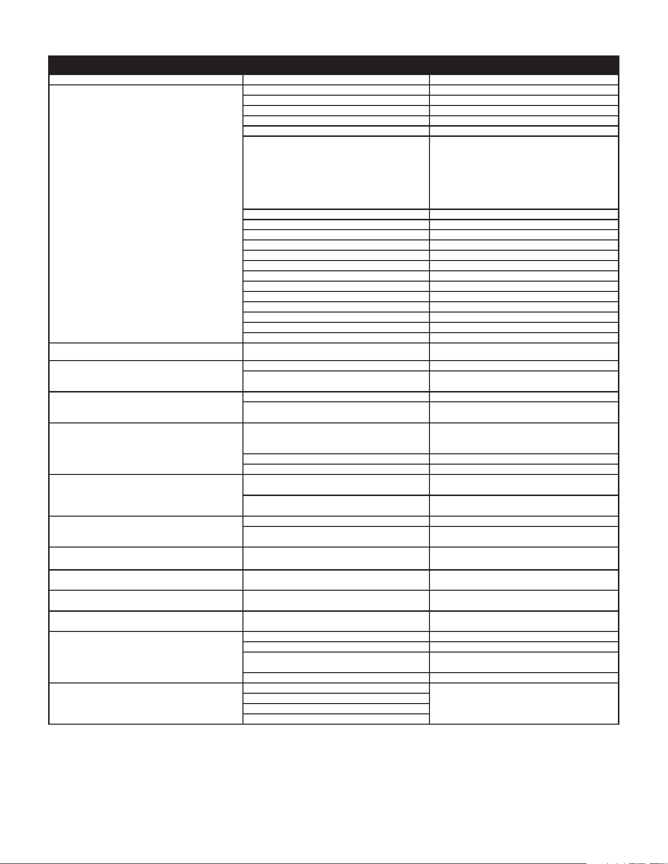
These guidelines should be utilized by a qualied service agent.
PROBLEM CAUSE SOLUTION
1.) Blower will not run
Not enough hot water
a. “ON/OFF” control switch turned o. Turn switch to the “ON” position.
b. Blower unplugged. Plug blower back into 115 VAC outlet.
c. No power at outlet. Repair service to outlet.
d. Thermostat defective. Replace gas control valve/thermostat.
e. Control harness defective. Replace control harness.
f. High limit control circuit open.
Reduce water temperature below 140°F (60°C).
Turn the power switch to the o position. Wait
10 seconds. Turn the power switch to the on
position. Reduce the temperature set point
to minimize likelihood of reoccurrence. If this
does not solve the problem, replace gas control
valve/thermostat.
g. Blower motor defective. Replace blower assembly.
h. Temperature/ECO probe defective. Replace temperature probe.
2.) Thermostat problems
a. Thermostat set too low. Adjust temperature control higher.
b. Thermostat or ECO defective. Replace thermostat.
c. Temperature/ECO probe defective Replace temperature probe.
d. “ON/OFF” thermostat switch turned o. Turn switch to the “ON” position.
3.) Others
a. Heater undersized. Reduce hot water use.
b. Low gas pressure. Contact dealer.
c. Incoming water is usually cold. Allow more time for the heater to reheat.
d. Leaking hot water pipes of xtures. Have plumber check and repair leaks.
e. Heater not lit or thermostat not on. See
Lighting And Operation Label
(page 34).
Vent pipe too hot (above 170° F [77° C]) Wrong burner orice. Install correct orice.
Yellow ame
Dirt in burner ports. Turn o heater and gas, clean burner head.
Combustion air path restricted.
Check exhaust venting and air openings in
bottom base pan for obstructions or blockage.
Condensation
Water on the oor under heater. See
Condensate Drain Installation
(page 28).
Water dripping from blower assembly.
Check the hose connections at blower and vent
pipe assembly #2.
Water leaks
Improperly sealed, hot or cold supply
connections, relief valve, drain valve or
temperature probe threads.
Check for leaks at all condensate points. See
Figure 1
(page 7) and
Figure 2
(page 8).
Also see
Leakage Checkpoints
(page 38).
Leakage from other appliances or water lines. Inspect other appliances near water heater.
Condensation of ue products. See
Condensate Drain Installation
(page 28).
Leaking T&P
Thermal expansion in closed water system.
Install thermal expansion tank (Do not plug T&P
valve).
Improperly sealed valve.
Check relief valve for proper operation (Do not
plug T&P valve).
Hot water odors
See
Smelly Water
(page 33).
High sulfate or mineral content in water supply. Drain and ush heater thoroughly then rell.
Bacteria in water supply. Chlorinate water supply.
Water too hot Thermostat set too high. See
Temperature Regulation
(page 31).
Water heater sounds Condensation dripping on burner. See
Condensate Drain Installation
(page 28).
Sizzling - rumbling Sediment at bottom of heater tank.
Clean sediment from tank. See
Draining and
Flushing
(page 39).
Sooting Improper combustion. See
Combustion Air and Ventilation
(page 16).
Burner will not stay lit -
goes out 4-5 seconds
Outlet polarity is reversed. Test polarity and correct.
High ambient room temperature. Contact a service agency to determine cause.
Combustion air path restricted.
Check exhaust venting and air openings in
bottom base pan for obstructions or blockage.
Defective gas valve. Replace gas valve.
Vent gas odors
Lack of air supply.
Shut o water heater immediately and contact a
service agency to determine cause.
Improperly installed vent piping.
Downdraft.
Poor combustion.
37
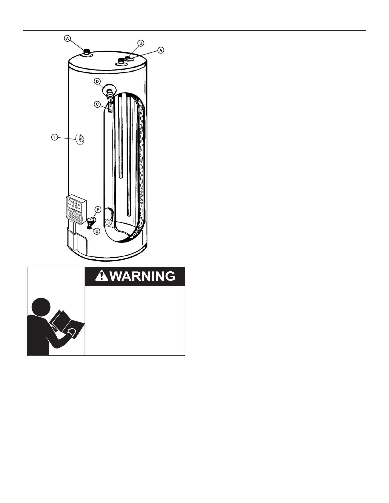
LEAKAGE CHECKPOINTS
Read and understand this instruction
manual and the safety messages
herein before installing, operating or
servicing this water heater.
Failure to follow these instructions and
safety messages could result in death
or serious injury.
This manual must remain with the
water heater.
A. *Condensation may be seen on pipes in humid weather or pipe
connections may be leaking.
B. *The anode rod tting may be leaking.
C. Small amounts of water from temperature-pressure relief valve
may be due to thermal expansion or high water pressure in your
area.
D. *The temperature-pressure relief valve may be leaking at the
tank tting.
E. Water from a drain valve may be due to the valve being slightly
opened.
F. *The drain valve may be leaking at the tank tting.
G. Combustion products contain water vapor which can condense on
the cooler surfaces of the tank. Droplets form and drip onto the
burner or run on the oor. This is common at the time of start-up
after installation and when incoming water is cold.
H. Water in the water heater bottom or on the oor may be from
condensation, loose connections, or the relief valve. DO NOT
replace the water heater until a full inspection of all possible water
sources is made and necessary corrective steps taken.
I. The temperature probe may be leaking at the tank tting.
Leakage from other appliances, water lines, or ground seepage
should also be checked.
* To check where threaded portion enters tank, insert cotton swab
between jacket opening and tting. If cotton is wet, follow “Draining”
instructions in the “Periodic Maintenance” section and then remove
tting. Put pipe dope or teon tape on the threads and replace. Then
follow “Filling the Water Heater” instructions in the “Installing the New
Water Heater” section.
38
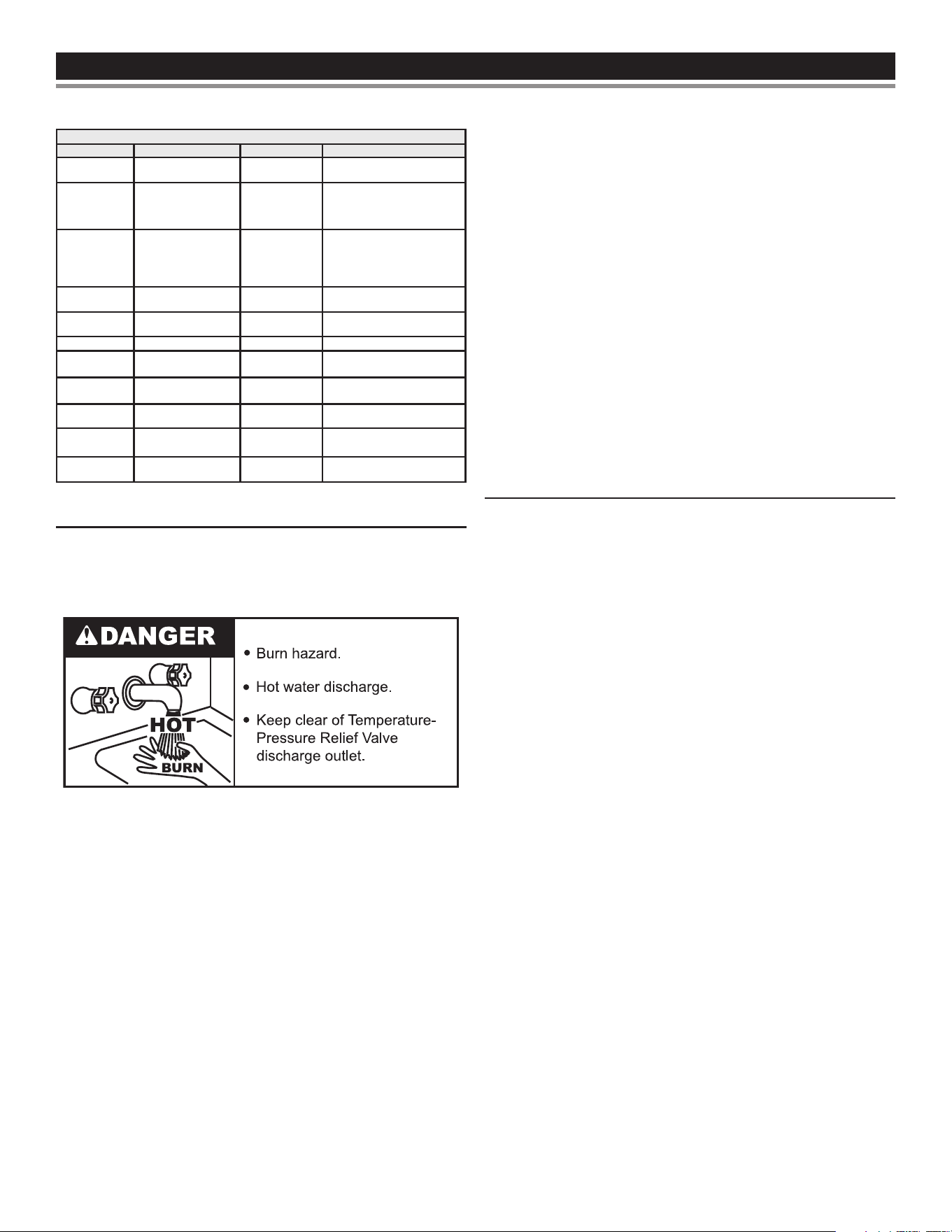
PERIODIC MAINTENANCEPERIODIC MAINTENANCE
Table 9. Maintenance Schedule
Component Operation Interval Reference
Tank Drain and Flush
Every 6
Months
See
Draining and Flushing
Tank
Lime Scale Re-
moval
(Water Less Than
25 Grains Hard)
Not Required N/A
Tank
Lime Scale Re-
moval
(Water Greater
Than 25 Grains
Hard)
Annually
See
Sediment and Lime Scale
Removal
.
Burner
Flames
Inspection
Every 3
Months
See
Burner Operation and
Inspection
(page 40).
Burner
Inspection/Clean-
ing
As Needed
Contact qualied agency or
professional.
Moving Parts Lubrication Not Required N/A
Powered
Anodes
Inspection/Clean-
ing
Annually
See
Anode Rod Inspection
(page 40).
T&P Valve Test Operation Semi Annually
See
Temperature-Pressure Relief
Valve Test
(page 40)
.
Vent System Inspection Annually
See
Burner Operation and
Inspection
(page 40).
Condensate
Neutralization
Inspection Annually
See manual for the conden-
sate neutralization kit.
Condensate
Collection
Cleaning Annually
See
Burner Operation and
Inspection
(page 40).
DRAINING AND FLUSHING
It is recommended that the water heater storage tank be drained and
ushed every 6 months to reduce sediment buildup. The water heater
should be drained if being shut down during freezing temperatures.
See
Features And Components
(page 7)
for location of the water
heater components described below.
TO DRAIN THE WATER HEATER STORAGE TANK:
1. Turn o the electrical supply to the water heater.
2. Turn o the gas supply at the Main Gas Shuto Valve if the water
heater is going to be shut down for an extended period.
3. Ensure the cold water inlet valve is open.
4. Open a nearby hot water faucet and let the water run until the
water is no longer hot.
5. Close the cold water inlet valve to the water heater.
6. Connect a hose to the water heater drain valve and terminate it
to an adequate drain.
7. Open the water heater drain valve and allow all the water to drain
from the storage tank.
8. Close the water heater drain valve when all water in the storage
tank has drained.
9. Close the hot water faucet opened in Step 4.
10. If the water heater is going to be shut down for an extended
period, the drain valve should be left open.
TO FLUSH THE WATER HEATER STORAGE TANK:
1. Turn o the electrical supply to the water heater.
2. Ensure the cold water inlet valve is open.
3. Open a nearby hot water faucet and let the water run until the
water is no longer hot. Then close the hot water faucet.
4. Connect a hose to the drain valve and terminate it to an adequate
drain.
5. Ensure the drain hose is secured before and during the entire
ushing procedure. Flushing is performed with system water
pressure applied to the water heater.
6. Open the water heater drain valve to ush the storage tank.
7. Flush the water heater storage tank to remove sediment and
allow the water to ow until it runs clean.
8. Close the water heater drain valve when ushing is completed.
9. Remove the drain hose.
10. Fill the water heater. See
Filling the Water Heater
(page 30).
11. Turn on electrical supply to place water heater back in operation.
12. Allow the water heater to complete several heating cycles to
ensure it is operating properly.
SEDIMENT AND LIME SCALE REMOVAL
Waterborne impurities consist of the particles of soil and sand which
settle out and form a layer of sediment on the bottom of the tank.
For convenience, sediment removal and lime scale removal should
be performed at the same time.
When water is heated dissolved minerals in the water such as
calcium and magnesium carbonate (lime scale) become less soluble.
As the water temperature rises these minerals will precipitate or “fall
out” of solution.
The amount of lime scale released from water is in direct proportion
to water temperature and usage. The higher the water temperature
or water usage, the more lime deposits are dropped out of the water.
Water hardness also aects lime scale accumulation. With the
temperature and usage being the same, hard water will release
more lime scale than softer water.
Lime scale reduces heating eciency as it accumulates inside a
water heater. Heating transfer surfaces become coated with lime
scale deposits which increases fuel costs to operate the water heater.
Lime scale deposits can also cause rumbling and pounding noises
as air molecules trapped in the lime scale escape when heated. Lime
scale accumulation also reduces the life span of water heaters. For
these reasons a regular schedule for deliming should be set up.
The depth of lime accumulation in the bottom of the water heater
should be measured periodically. Inspect by removing the cleanout
cover once every 6 months at rst. Deliming maintenance should
then be performed based on the time it takes for 1 inch (2.5 cm) of
lime to accumulate in the bottom of the water heater.
CHEMICAL LIME SCALE REMOVAL
To dissolve and remove more stubborn lime scale deposits, UN-
LIME
®
Professional Delimer should be used.
UN-LIME
®
Professional Delimer is an easy to handle patented food
grade acid formulated specically for lime scale removal from all
types of water using equipment. Hydrochloric base acids must not
be used to delime the water heaters covered in this manual.
Follow the instructions on the UN-LIME
®
to delime the water heater.
39
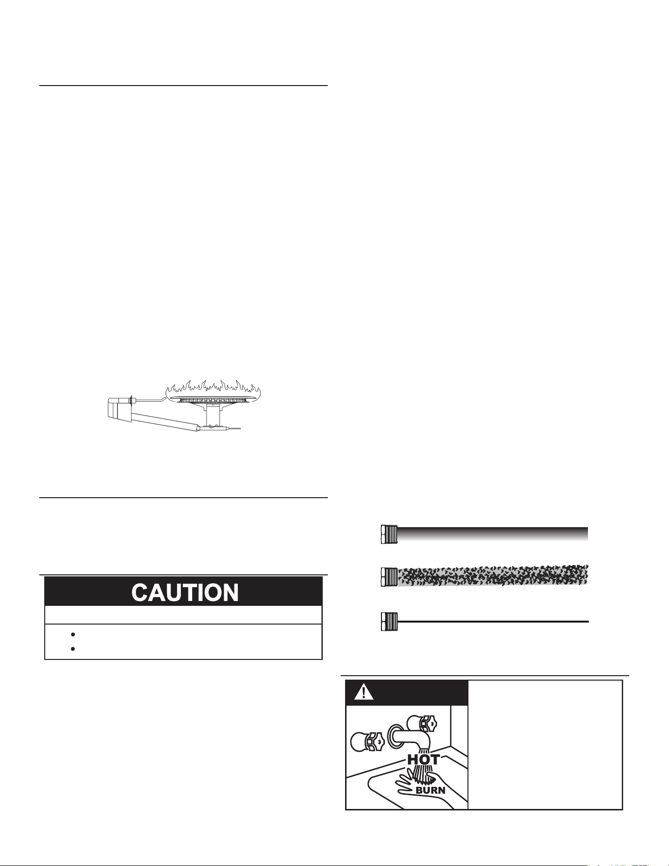
Note: Contact Technical Support for assistance in ordering the
UN-LIME
®
Professional Delimer.
BURNER OPERATION AND INSPECTION
Flood damage to a water heater may not be readily visible or
immediately detectable. However, over a period of time a ooded
water heater will create dangerous conditions which can cause
DEATH, SERIOUS BODILY INJURY, OR PROPERTY DAMAGE.
Contact a qualied installer or service agency to replace a ooded
water heater. Do not attempt to repair the unit! It must be replaced!
At least once a year a visual inspection should be made of the
main burner and the hot surface igniter assembly for proper ame
characteristics and ignition sequences. This can be done by removing
the Outer Door and viewing the main burner operation through the
Viewport on the Inner Door. See
Figure 1
(page 7). The main
burner should provide complete combustion of gas, ignite rapidly,
give reasonably quiet operation, and cause no excessive ame
lifting from the burner ports. If the proper ame characteristics are
not evident, make sure that the ow of combustion and ventilation
air is not blocked. See
Figure 30.
You should also check for sooting. Soot is not normal and will impair
proper combustion. A visual inspection of the main burner and HSI
should also be done at least once a year.
Soot build-up indicates a problem that requires correction before
further use. Turn “OFF” gas to water heater and leave o until repairs
are made, because failure to correct the cause of the sooting can
result in a re causing death, serious injury, or property damage.
Figure 30. Abnormal Flame
BURNER CLEANING
In the event your burner or burner air openings require cleaning, turn
the blower switch to the “OFF” position and allow the burner to cool.
Call a service agency to remove and clean the burner and correct
the problem that required the burner to be cleaned.
ANODE ROD INSPECTION
Avoid damage.
Property Damage Hazard
Inspection and replacement of anode rod required.
Each water heater contains at least one anode rod, which
will slowly deplete (due to electrolysis) prolonging the life
of the water heater by protecting the glass-lined tank from
corrosion. Adverse water quality, hotter water temperatures,
high hot water usage, and water softening methods can
increase the rate of anode rod depletion. Once the anode rod
is depleted, the tank will start to corrode, eventually developing a
leak.
Certain water conditions will cause a reaction between the anode rod
and the water. The most common complaint associated with the
anode rod is a “rotten egg smell” produced from the presence of
hydrogen sulde gas dissolved in the water.
Important: Do not remove this rod permanently as it will void
any warranties. The parts list includes a special
anode rod that can be ordered if water odor or
discoloration occurs.
This rod may reduce but not eliminate water
odor problems. The water supply system may
require special ltration equipment from a water
conditioning company to successfully eliminate all
water odor problems.
Articially softened water is exceedingly corrosive because the
process substitutes sodium ions for magnesium and calcium ions.
The use of a water softener may decrease the life of the water
heater tank.
The anode rod should be removed from the water heater tank every
3 years for inspection. NOTE: articially softened water requires the
anode rod to be inspected annually.
The following are typical (but not all) signs of a depleted anode rod:
• The majority of the rods diameter is less than 3/8”.
• Signicant sections of the support wire (approx. 1/3 or more of
the anode rod’s length) are visible.
Note: If the anode rod show signs of either or both it should be
replaced. Whether re-installing or replacing the anode rod,
check for any leaks and immediately correct if found.
In replacing the anode:
1. Turn o gas supply to the water heater.
2. Shut o the water supply and open a nearby hot water faucet to
depressurize the water tank.
3. Drain approximately 5 gallons of water from tank. See
Draining and
Flushing
(page 39) for proper procedures. Close drain valve.
4. Remove old anode rod.
5. Use Teon® tape or approved pipe sealant on threads and install
new anode rod.
6. Turn on water supply and open nearby hot water faucet to purge
air from water system. Check for any leaks and immediately
correct any if found.
7. Restart the water heater as directed in
Start Up
(page 33).” See
Figure 1
(page 7)
for anode rod location.
New Unused Anode Rod
Partially-Consumed Anode Rod
Fully-Depleded Anode Rod
Figure 31. Anode Rod Depletion
TEMPERATURE-PRESSURE RELIEF VALVE TEST
DANGER
• Burn hazard.
• Hot water discharge.
• Keep clear of Temperature-
Pressure Relief Valve
discharge outlet.
40
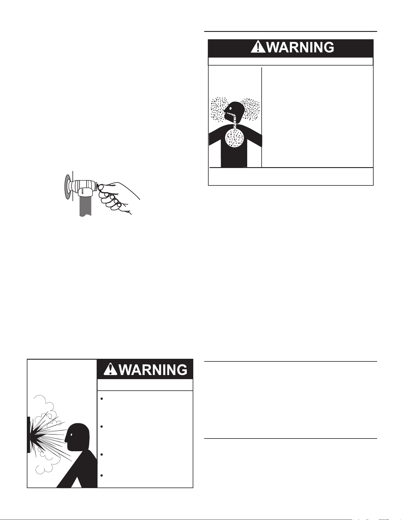
It is recommended that the Temperature-Pressure Relief Valve
should be checked to ensure that it is in operating condition every
6 months.
When checking the Temperature-Pressure Relief Valve operation,
make sure that (1) no one is in front of or around the outlet of the
Temperature-Pressure Relief Valve discharge line, and (2) that
water discharge will not cause any property damage, as water may
be extremely hot. Use care when operating valve as the valve may
be hot.
To check the relief valve, lift lever at the end of valve several times.
See
Figure 32
. The valve should seat properly and operate freely.
If after manually operating the valve, it fails to completely reset and
continues to release water, immediately close the cold water inlet to
the water heater and drain the water heater. See
Draining and Flushing
(page 39). Replace the Temperature-Pressure Relief Valve with
a properly rated/sized new one.
See
Temperature-Pressure Relief Valve
(page 15) for instructions on
replacement.
DISCHARGE PIPE
TEMPERATURE-PRESSURE
RELIEF VALVE
Figure 32. Testing the Temperature-Pressure Relief Valve
If the Temperature-Pressure Relief Valve on the water heater weeps
or discharges periodically, this may be due to thermal expansion.
Note: Excessive water pressure is the most common cause of
Temperature-Pressure Relief Valve leakage. Excessive
water system pressure is most often caused by “thermal
expansion” in a “closed system.” See
Closed Water Systems
(page 14)
and
Thermal Expansion
(page 14). The
Temperature-Pressure Relief Valve is not intended for the
constant relief of thermal expansion.
Temperature-Pressure Relief Valve leakage due to pressure build
up in a closed system that does not have a thermal expansion
tank installed is not covered under the limited warranty. Thermal
expansion tanks must be installed on all closed water systems.
DO NOT PLUG THE TEMPERATURE-PRESSURE RELIEF VALVE
OPENING. THIS CAN CAUSE PROPERTY DAMAGE, SERIOUS
INJURY OR DEATH.
Explosion Hazard
Temperature-Pressure Relief Valve
must comply with ANSI Z21.22-
CSA 4.4 and ASME code.
Properly sized temperature-
pressure relief valve must be
installed in opening provided.
Can result in overheating and
excessive tank pressure.
Can cause serious injury or death.
VENT SYSTEM MAINTENANCE
Breathing Hazard - Carbon Monoxide Gas
•
Flue gases may escape if vent pipe is not
connected
•
Be alert for obstructed, sooted, or deteriorated
vent system to avoid serious injury or death.
•
Do not store corrosive chemicals in the
vicinity of the water heater
.
•
Chemical corrosion of the flue and vent system
can cause serious injury or death
.
•
Analyze the entire vent system to make sure that
condensate will not become trapped in a section
of vent pipe and therfore recuce the open cross
sectional area of the vent.
Breathing carbon monoxide can cause brain damage or
death. Always read and understand instruction manual.
At least once a year a visual inspection should be made of the venting
system. You should look for:
1. Obstructions which could cause improper venting. The
combustion and ventilation air ow must not be obstructed.
2. Damage or deterioration which could cause improper venting or
leakage of combustion products.
Be sure the vent piping is properly connected to prevent escape
of dangerous ue gasses which could cause deadly asphyxiation.
Obstructions and deteriorated vent systems may present serious
health risk or asphyxiation.
Chemical vapor corrosion of the ue and vent system may occur
if air for combustion contains certain chemical vapors. Spray can
propellants, cleaning solvents, refrigerator and air conditioner
refrigerants, swimming pool chemicals, calcium and sodium chloride,
waxes, bleach and process chemicals are typical compounds which
are potentially corrosive.
If after inspection of the vent system you found sooting or
deterioration, something is wrong. Call the local gas utility to
correct the problem and clean or replace the ue and venting before
resuming operation of the water heater.
HOUSEKEEPING
Vacuum around base of water heater for dust, dirt, and lint on a
regular basis.
INSTALLED IN SUITABLE AREA: To insure sucient ventilation
and combustion air supply, proper clearances from the water heater
must be maintained. See
Locating the New Water Heater
(page 10).
Combustible materials such as clothing, cleaning materials, or
ammable liquids, etc. must not be placed against or adjacent to
the water heater which can cause a re.
SERVICE
If a condition persists or you are uncertain about the operation of
the water heater contact a service agency.
Use this guide to check a “Leaking” water heater. Many suspected
“Leakers” are not leaking tanks. Often the source of the water can
be found and corrected.
41

If you are not thoroughly familiar with gas codes, your water heater,
and safety practices, contact your gas supplier or qualied installer
to check the water heater.
Read this manual rst. Then before checking the water heater make
sure the gas supply has been turned “OFF”, and never turn the gas
“ON” before the tank is completely full of water.
Never use this water heater unless it is completely lled with water.
To prevent damage to the tank, the tank must be lled with water.
Water must ow from the hot water faucet before turning “ON” gas
to the water heater.
42
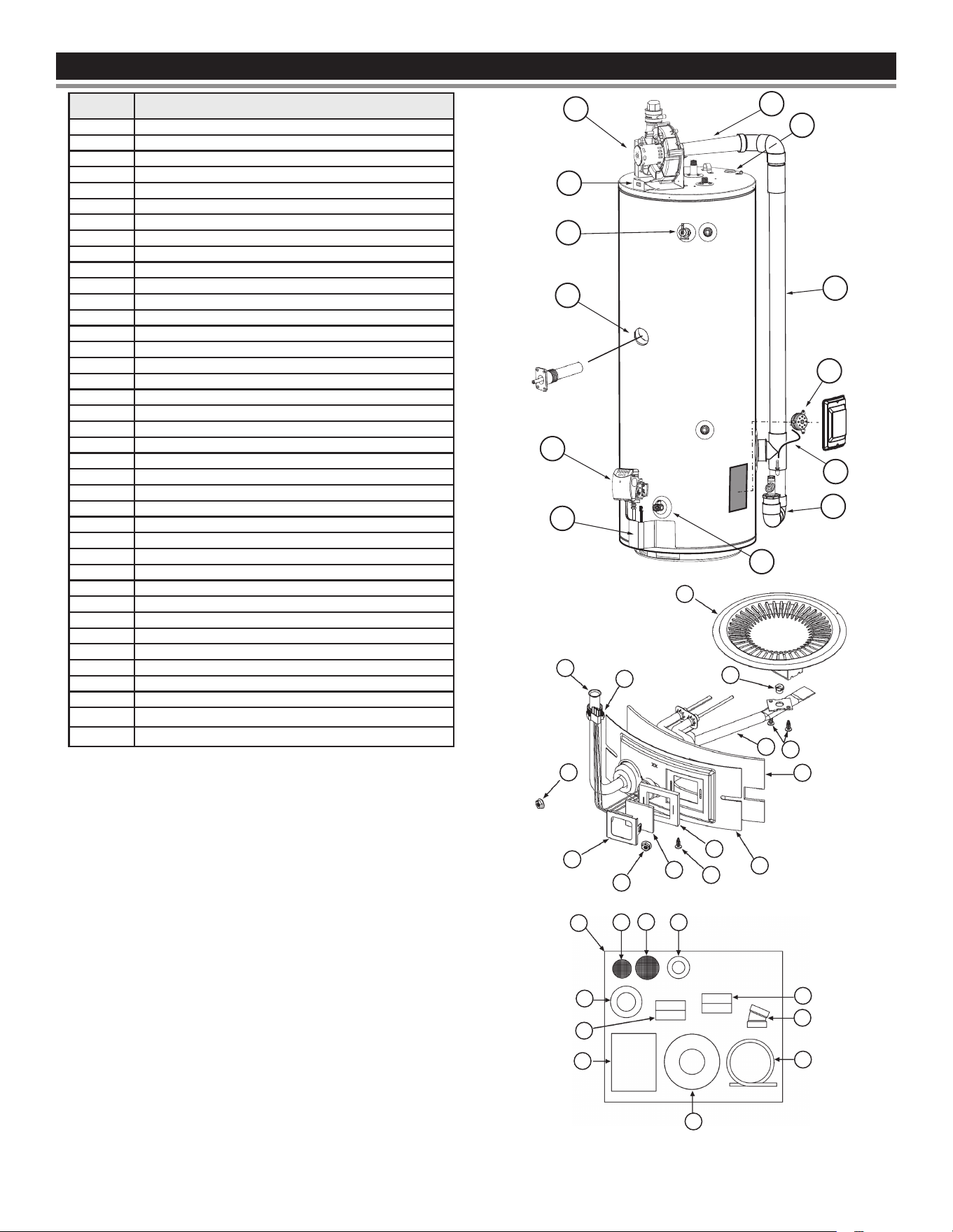
REPAIR PARTS LISTREPAIR PARTS LIST
Key No. Part Description
1 Outer Door
2 Anode
3 Control Valve Assembly
4 Plastic Top
5 Blower Assembly
6 Switch and Harness Assembly
7 T&P Valve
8 Drain Valve
9 Wiring Harness
10 Anode Outlet
11 Vent Pipe Assembly #1
12 Vent Pipe Assembly #2
13 Vent Pipe Assembly #3
14 Inlet Tube
15 Pipe Nipple
16 Temperature Probe
17 Burner Tube Assembly
18 Hot Surface Igniter
19 Burner Head Assembly
20 Embossed Inner Door
21 Insulation - Inner Door
22 Insulation - Viewport
23 Window - Observation
24 Viewport
25 Nut - Serrated Hex Flange
26 Screw - Sheet Metal, # 8-15
27 Orice - Burner
28 Vent Kit Assembly
29 Wall Plate 2”
30 Wall Plate 3”
31 Screen and Vent Terminal Assembly
32 Instruction Tag-Wire Screen F/E 3”
33 Instruction Tag-Wire Screen F/E 4”
34 Instruction Sheet
35 Wire Screen 3”
36 Wire Screen 4”
37 Wall Plate 4”
38 Flexible Tubing
39 Pressure Switch - Blocked Condensate
Now that you have purchased this water heater, should a need ever
exist for repair parts or service, simply contact the company it was
purchased from or direct from the manufacturer listed on the rating
plate on the water heater.
Be sure to provide all pertinent facts when you call or visit.
Selling prices will be furnished on request or parts will be shipped
at prevailing prices and you will be billed accordingly.
The model number of your Gas Water Heater will be found on the
rating place located above the gas control valve.
WHEN ORDERING REPAIR PARTS, ALWAYS GIVE THE
FOLLOWING INFORMATION:
• MODEL NUMBER
• TYPE GAS (NATURAL OR PROPANE (L.P.)
• SERIAL NUMBER
• PART DESCRIPTION
THIS IS A REPAIR PARTS LIST, NOT A PACKING LIST. Parts are
not drawn to scale.
EMERSON
16
13
12
11
2
6
5
7
3
8
9
1
39
27
17
26
21
18
17
25
24
25
23
26
22
20
19
17
18
25
24
25
23
26
22
20
21
26
17
27
19
29
36
35
28
30
32
34
37
38
31
33
36
2935
28
30
32
34
37
38
31
33
43

WIRING DIAGRAMWIRING DIAGRAM
CAUTION
Label all wires prior to disconnection when servicing controls.
Wiring errors can cause improper and dangerous operation. Verify
proper operation after servicing
.
● Disconnect from electrical supply before
servicing unit. Replace all doors and
panels before operating heater.
Electrical Shock Hazard
● If any of the origina wires supplied with
the appliance must be replaced, it must
be replaced with appliance wire material
with minimum temperature rateing of
105°C and a minimum size of No. 18 AWG.
WATER HEATER CONTROL
IGN
IGN
RS
120V
120V
120V
120V
PS
PS
GROUND
GND
GND
NTC
NTC
NORMAL OPERATION SEQUENCE
INDICATED BY BOXED NUMERALS
IGNITOR
FLAME SENSE ROD
5
6
2
1
7
GAS VALVE
TEMPERATURE
SENSOR
ON/OFF
SWITCH
4
BLOWER
VACUUM
SWITCH
(EXHAUST
BLOCKAGE)
3
BLOWER
MOTOR
M
~
GNDL2L1
LEGEND
Y=YELLOW
Y/BK=YELLOW/BLACK
G/Y=GREEN/YELLOW
W/BK=WHITE/BLACK
T=TAN
O= ORANGE
BK=BLACK
BL=BLUE
W=WHITE
R=RED
G=GREEN
W
BK
BL
W
R
R
BLOWER
POWER
SWITCH
120 V
B
K
W
G/Y
N.O.
PRESSURE SWITCHES
BK
GAS VALVE
R
R
BK
R
G G
R
TEMPERATURE
SENSOR
FLAME ROD
HOT SURFACE IGNITER
T
T
T
N.C.
VENT
TEMP.
LIMIT
SWITCH
4
VENT
TEMPERATURE
LIMIT
SWITCH
BK
BK
W
NTC
NTC
NTC
NTC
4.5
3
BLOCKED
CONDENSATE
SWITCH
N.O.
BL
BL
BL
O
O
O
Figure 33. Wiring Schematic
Note: If any of the original wires supplied with the appliance
must be replaced, it must be replaced with appliance
wire material with minimum temperature rating of 105ºc
and a minimum size of no. 18 Awg.
44

NOTESNOTES
45

NOTESNOTES
46

NOTESNOTES
47

Copyright © 2021. All rights reserved.