SC90XZB-100-01
Installer Guide
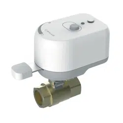
Inline Water Shutoff Valve
SC904ZB 3/4” Inline Water Shutoff Valve
SC907ZB 1” Inline Water Shutoff Valve
SC908ZB 1¼” Inline Water Shutoff Valve
Installation should be performed by a licensed plumber.
Install in accordance with local plumbing codes.
Turn off water supply before beginning installation.
The manufacturer does not accept responsibility for any damage caused by DIY
installations or not following these instructions.
Side View Front View
Dimensions (in/mm)
Model
SC904ZB
SC907ZB
SC908ZB
Length
5.68/144
5.68/144
5.68/144
Width
2.85/72.3 *
2.85/72.3 *
2.85/72.3 *
Height
4.90/124.5
5.60/142.3
6.13/155.3
Valve connection
¾” NPT
1” NPT
1¼“ NPT
Valve Length
2.60/66.0
3.56/90.4
4.09/103.9
* Allow 1 ½ “ clearance for when valve is closed
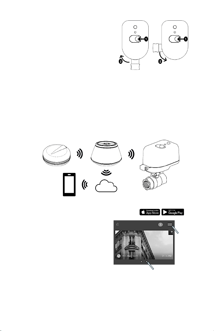
1. FEATURES
• Third-party certified to NSF/ANSI 61-G & 372 for compliance with the National Safe
Drinking Water Act.
• Three options to operate the valve:
o Manually Close/Open using the Clutch release.
o Close/Open using multi-function button.
o Close automatically when a leak is detected (requires Gateway, Smart Connect App
and SS901ZB water leak sensors – sold separately).
• AC Power adapter with 13-foot (3m) cable length.
1 FEATURES 2 INSTALLATION 3 LED INDICATOR STATUS 4 CONTROLS
5 PAIRING 6 AUTOMATIONS 7 FACTORY RESETTING THE DEVICE
Installer Guide
2
2. INSTALLATION
• Identify the location for the Shutoff Valve depending on the desired water outlet
to be controlled. Make sure of the
following:
o The location is accessible and
allows operation of the Manual
Override button and lever.
o The path of the Manual Override
Lever is clear of any obstructions.
• Install the valve using the appropriate
adapters and materials required for the
plumbing at the location.
Once attached to the plumbing, apply power as
follows:
• Remove plug from power jack u.
• Insert barrel plug from power adapter into
power jack v.
• Run power cable to AC outlet, using cable clips as
required w.
• Plug power adapter into AC outlet.
3. LED INDICATOR STATUS
Solid yellow at power up:
Initializing device
3 yellow flashes, pause and repeat:
Searching for network
Green flash, pause and repeat:
Connected to network
Yellow, green flash, pause and repeat:
Multi-Function Button jammed
Solid green at power up:
Factory Reset Request detected
Solid red:
Obstruction encountered
4. CONTROLS
There are 3 options to operate the valve:
1.
Multi-Function Button
Electrically Open, Close, or position the valve.
• Press the Multi-Function Button and the
valve will begin to Open or Close
depending on the starting point.
• Allow the valve to move to the fully Open
or Closed position and it will stop.
or
• Press the button to stop the valve motion
at the desired position.
Manual Override Lever
Manual Override
Clutch
LED
Indicator
Multi-Function
Button
Installer Guide
3
2.
Manual Override Clutch release
Mechanically Open, Close, or
position the valve.
• Press and hold the Manual
Override Clutch.
• Move the Manual Override
Lever to the desired valve
position.
• Release the Manual Override
Clutch to re-engage the motor.
3.
Automatically triggering the valve to Close (requires SG888ZB and SS901ZB
sold separately)
• Use a SALUS Gateway (sold separately) to create the wireless network.
• Add the Inline Shutoff Valve to the wireless network.
• Add a SS901ZB Wireless leak detector (sold separately) to the network.
• Use the SALUS Smart Connect App to create an Automation that closes
the valve if a leak is detected.
• Use this Automation to send an alert email or text message if connected
to the internet.
5. PAIRING
Download and install the Salus Smart Connect App from
Open the App and sign in or create a new
account if you do not already have one.
1. Install the Gateway following the
instructions included in the package.
2. The App opens the Smart Home
Dashboard with a Gateway selected.
a. If there is more than one Gateway
associated with your account:
i. Swipe left or right to display
the desired Gateway or Location or
ii. Tap the ‘Hamburger’ menu icon:
1. Tap Locations from the drop-down menu.
2. Tap the desired Location.
Dots indicate Locations
or Gateway systems
Hamburger
Menu
u
Water leak
detected
v Message
sent to
Gateway
w Automation
Rules run
x Command
to close
valve
z Email/Text
sent to user
y Notification
sent to
cloud
Installer Guide
4
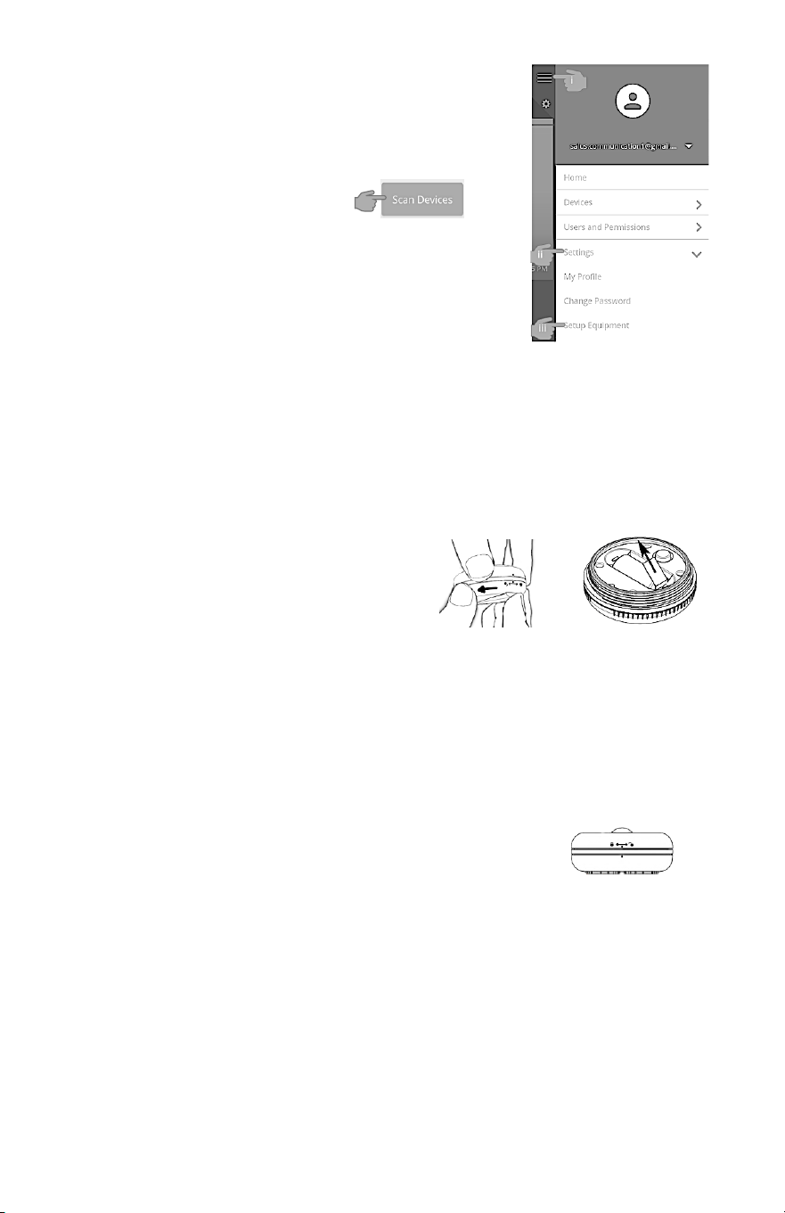
3. To Add devices to your wireless mesh network:
a. From the Smart Connect App Dashboard:
i. Tap the Hamburger Menu icon.
ii. Tap Settings from the drop-down menu.
iii. Tap Setup Equipment from the expanded
menu.
iv. A new page will
open, tap Scan
Devices.
v. A New page will open showing the
Gateway is Scanning for devices.
This may take a few minutes.
NOTE: The Gateway will time out after 15
minutes.
b. Prepare the devices to Join or Pair with the Gateway:
i. Inline Shutoff Valve:
1. On initial power up out of the box, after initialization, the LED
should flash Yellow: 3 times, pause, repeat.
2. If not:
a. Remove power from the device.
b. Press and hold the Multi-Function button.
c. Reapply power and wait for the LED to flash as above.
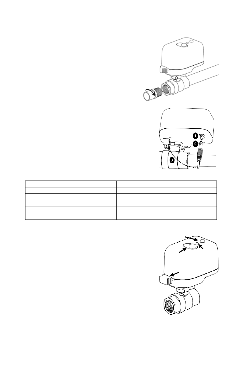
ii. Water Leak Sensor
1. Remove the cover by
rotating counterclockwise.
2. Remove the Red battery tab
to power the device.
3. The SS901ZB LED will flash
Red: 3 times, pause, repeat for 6 cycles and then go to ‘Sleep’.
4. If the LED does not blink Red 3 times:
a. Tap the Multi-Function button to reinitiate Pairing.
b. If it does not blink now, perform a factory reset:
i. Remove the battery.
ii. Press and hold the Multi-Function button while reinserting
the battery.
iii. Release the Multi-Function button within 4 seconds of
reinserting the battery.
5. Replace the cover making certain to align
the two dots on the top and bottom of the
cover.
Installer Guide
5
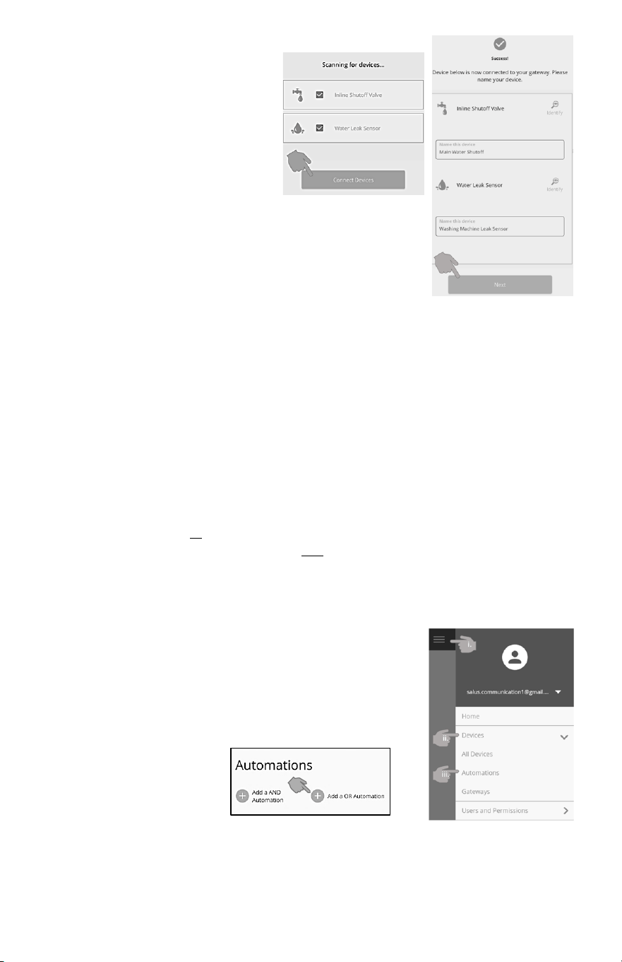
c. “Joining” devices with the network created by the
Gateway.
i. Once the devices
are found, check the
boxes for the those
you wish to add.
Tap Connect
Devices.
ii. Give the devices a meaningful name so that
it is easily identifiable.
Tap Next to save the name.
iii. A new page will open. Tap Finish to
complete.
6. AUTOMATIONS
Automations are a feature of the SALUS Smart Connect App and provide a powerful
WHEN
/
DO THIS
programming language that is menu driven to make it simple to create
multifaceted control sequences.
Automations are stored in the SALUS Gateway and will execute even if the Gateway
loses its connection to the internet.
• The
WHEN
is a trigger to initiate an action based on an event or condition.
Example: a SS901ZB Leak Sensor detects moisture.
• The
DO THIS
is the action the device is to perform when the event occurs.
Example: the SC904ZB Shutoff Valve is to close.
There are 2 types of Automations:
• An AND – requires all
WHEN
triggers to be ‘true’ to trigger a
DO THIS.
• An OR – a
DO THIS
will be initiated if any
WHEN
trigger is ‘true’.
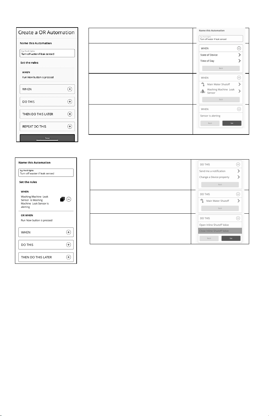
For this example, we will use an
OR Automation
that closes the Shutoff Valve and sends
a text and email notification to a user, if a water leak is detected.
To begin, open the SALUS Smart Connect App.
1. To create the Automation:
i. Tap the
Hamburger Menu
icon.
ii. Tap
Devices
from the drop-down menu.
iii. Tap
Automation
from the expanded menu.
2. A new page will open:
Tap
OR
Automation
(any
WHEN
will trigger
the Automation).
Installer Guide
6
3. A new page opens allowing you to define the
WHEN
trigger and
DO THIS
actions.
4. You will return to the Automation page to define the
DO THIS
action.
Give the Automation a meaningful
name.
Tap
WHEN
Then tap State of Device to set the
trigger for the
DO THIS
action.
Tap Washing Machine Leak Sensor
to be used to trigger the
DO THIS
action.
Tap the event that will be used
trigger the
DO THIS
action.
Tap
Set
, to save and return to the
program page.
Tap
DO THIS.
Tap the action to perform:
Change a Device Property.
Tap to select the device.
Main Water Shutoff
Tap the action the device is to take.
Close the Shutoff Valve
Tap
Set.
Installer Guide
7
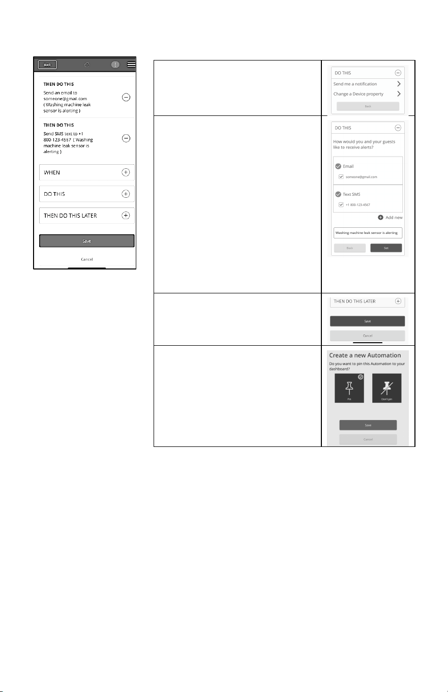
5.
Create a second DO THIS to send a Notification
7. FACTORY RESETTING THE DEVICE
If the device is unresponsive, or you want to reinitiate the Pairing process:
• Remove power by unplugging the power adapter from the outlet or plug from the
device.
• Press the Multi-Function Button and apply power the device.
• Release the button when the Status LED turns solid green. The device will now
respond to pairing requests.
Tap
DO THIS
.
Then tap Send me a notification.
If you have not previously entered
contact information you will see
this page.
Tap the + button to add new
contact cell number and email
address.
Add the information.
Or
Check the box of an existing email
or text number.
Type a descriptive message you
would like to receive tap
Set.
Tap
Save.
A new page will open allowing you
to “Pin” the new Automation to the
dashboard.
Tap
Pin.
Tap
Save.

Installer Guide
8
This equipment has been tested and found to comply with the limits for a Class B digital device, pursuant
to Part 15 of the FCC Rules. These limits are designed to provide reasonable protection against harmful
interference in a residential installation. This equipment generates uses and can radiate radio frequency
energy and, if not installed and used in accordance with the instructions, may cause harmful interference to
radio communications. However, there is no guarantee that interference will not occur in a particular
installation. If this equipment does cause harmful interference to radio or television reception, which can be
determined by turning the equipment off and on, the user is encouraged to try to correct the interference
by one or more of the following measures:
• Reorient or relocate the receiving antenna.
• Increase the separation between the equipment and receiver.
• Connect the equipment into an outlet on a circuit different from that to which the receiver is connected.
• Consult the dealer or an experienced radio/TV technician for help.
Changes or modifications not expressly approved by the party responsible for compliance could void the
user’s authority to operate the equipment. This device complies with part 15 of the FCC Rules. Operation is
subject to the following two conditions: (1) This device may not cause harmful interference, and (2) this
device must accept any interference received, including interference that may cause undesired operation.
This device complies with Industry Canada’s license-exempt RSSs. Operation is subject to the following
two conditions:
(1) This device may not cause interference; and
(2) This device must accept any interference, including interference that may cause undesired operation of
the device.
Cet appareil est conforme aux CNR exempts de licence d’Industrie Canada. Son fonctionnement est
soumis aux deux conditions suivantes :
(1) Ce dispositif ne peut causer des interf é rences ; et
(2) Ce dispositif doit accepter toute interf é rence , y compris les interf é rences qui peuvent causer un
mauvais fonctionnement de l’appareil.
Please Note: This device may have been updated over the internet since this manual was printed. Always
refer to the support web site for the latest information.
Limited Warranty
When installed by a professional contractor, this product is backed
by a 5-year limited warranty. Limitations apply. For limitations, terms,
and conditions, you may obtain a full copy of this warranty:
· Visit us online: www.braeburnonline.com/warranty
· Phone us: 866.268.5599
· Write us: Braeburn Systems LLC
2215 Cornell Avenue
Montgomery, IL 60538
Braeburn Systems LLC
2215 Cornell Avenue • Montgomery, IL 60538
Technical Assistance: www.braeburnonline.com
Call us toll-free: 866-268-5599 (U.S.)
630-844-1968 (Outside the U.S.)
©2024 Braeburn Systems LLC Ä All Rights Reserved. SC90XZB-100-01