User manual
DES4111R/27
Home alerts
MADE IN CHINA
Philips and the Philips Shield Emblem are registered trademarks
of Koninklijke Philips N.V. and are used under license. This product
has been manufactured by and is sold under the responsibility of
Jasco Products Company, and Jasco Products Company LLC,
10 E. Memorial Rd., Oklahoma City, OK 73114, USA is the warrantor
in relation to this product.
This product comes with a 90-day limited warranty.
Visit www.philips.com/support for warranty details.
Questions? Contact our U.S.-based Consumer Care at
1-844-816-0320 between 7AM-8PM, M-F, Central Time.
100%
recyclable
Separate
paper
from plastic
before
recycling
byjasco.com/recycle
paper made from 25%
post consumer waste
Having issues and need support?
Call our U.S.-based experts Monday–Friday,
from 7AM–8PM (Central Time)
1-844-816-0320
II. INSTALLATION
INSTALLATION cont.
I. DIRECT WIRE PUSH BUTTON
v1 4/2020
21
Fig. 1
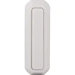
• This product replaces an existing wired doorbell button
• This button is not for use on doorbell systems which
exceed 24 volts.
• Not intended for use in direct rain.
• This product is not intended for use with Philips
wireless doorbell kits.
• #2 Phillips screwdriver • small at blade screwdriver
Items required for installation and use (not included)
Mounting screws are included inside the package behind
the product.
NOTE: Push buttons are typically mounted at the same height as
the doorknob or handle between 36” and 44” above the oor.
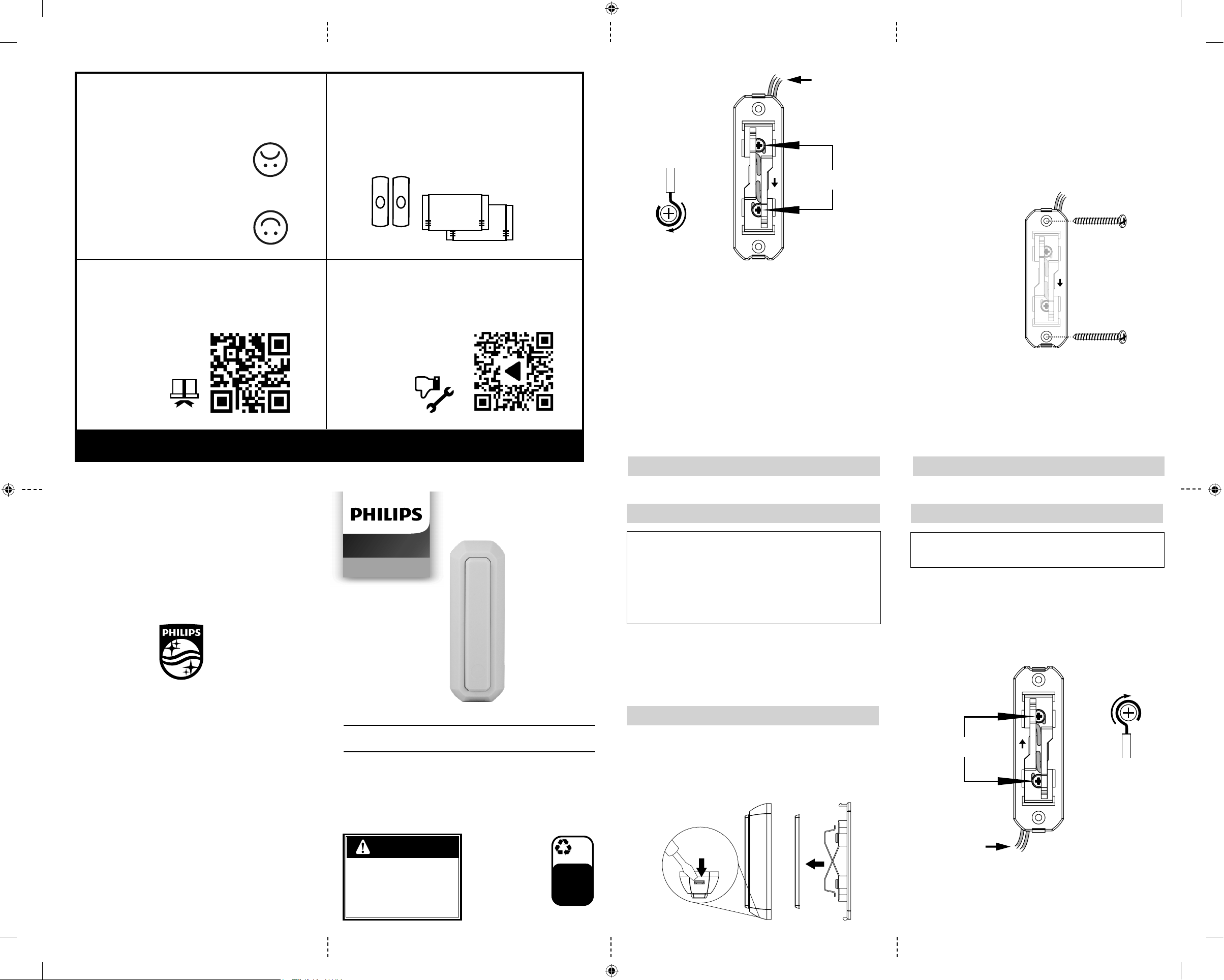
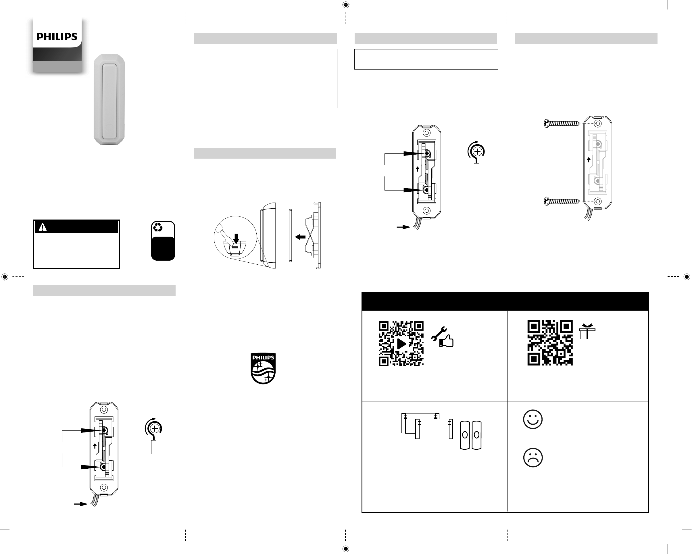
1. Use a small at blade screwdriver to release the cover of the
push button. (Fig. 1)
2. Gently remove contact cover to reveal screw terminals.
4. Remove the old push button and detach the wires.
5. Locate the two door chime wires connected to the existing
door chime circuit.
6. Attach one wire to each of the screw terminals on the back of the
push button. (Fig. 2)
Turn o power at fuse box or circuit breaker before
proceeding with installation.
up
Fig. 2
Chime wires
from wall
Form wire
clockwise
3/4 around
terminals.
Do not overlap.
Screw
terminals
RISK OF ELECTRIC SHOCK
• SHUT OFF POWER AT FUSE BOX
OR CIRCUIT BREAKER BEFORE
INSTALLATION.
RISK OF ELECTRIC SHOCK
• DO NOT EXCEED ELECTRICAL
RATINGS.
WARNING
7. Mount button in desired location with the two screws provided.
Ensure the arrow on the back housing is pointing upwards.
Install according to applicable local electrical codes. (Fig. 3)
8. Replace contact cover. Ensure the arrow on back of the
contact cover is pointing upward.
9. Snap the front housing in place. The slot to open the housing
should be facing downward.
INSTALLATION cont.
III. TROUBLESHOOTING
Fig. 3
Mount
securely
in desired
location
with the
two screws
provided.
up
10. Turn on power on circuit breaker. Test the new push button to
ensure doorbell is operational.
up
Fig. 2
Chime wires
from wall
Form wire
clockwise
3/4 around
terminals.
Do not overlap.
Screw
terminals
If the door chime does not sound once your new push
button is installed...
1. Remove the wires (coming out from the walll) from the
push button.
2. Test the wired door chime system by touching the two wires
(coming out from the wall) together, completing the circuit with
your chime and causing it to sound.
If the chime DOES NOT sound:
• check the (power) transformer to the door chime
• check the door chime unit and wiring
If the chime DOES sound:
• reconnect the wires to the screw terminals of the push button
using the correct winding procedure. (Fig. 2)
Scan to watch a step-by-step
instructional video, or visit
https://byjasco.com/49911i
Get exclusive, web-only deals
and more! Scan here, or visit
byjasco.com/deals
Like our product?
Leave us a review on
Amazon.com or your
favorite retailer website!
Having issues and
need support?
Call our U.S.-based
experts Monday–Friday,
from 7AM–8PM (Central)
1-844-816-0320
Product
instructions
made easy
For additional Philips doorbell
receivers, push buttons and
more, visit our website!
byjasco.com/chimes
Need more
accessories?
Register
your Philips
product
THANK YOU FOR YOUR PURCHASE!
DES4111R_27 EnSp v1.indd 1DES4111R_27 EnSp v1.indd 1 4/30/20 9:45 AM4/30/20 9:45 AM
7. Monte el botón en la ubicación deseada con los dos tornillos
provistos. Asegúrese de que la echa en el recinto posterior
apunte hacia arriba. Instale de acuerdo con los códigos eléctricos
locales correspondientes. (Fig. 3)
8. Vuelva a colocar la tapa de contacto. Asegúrese de que la echa
en la parte posterior de la tapa de contacto apunte hacia arriba.
9. Presione el recinto delantero para sujetarlo en su lugar. La ranura
para abrir el recinto debe estar hacia abajo.
100%
recyclable
Separate
paper
from plastic
before
recycling
byjasco.com/recycle
paper made from 25%
post consumer waste
INSTALACIÓN
v1 4/2020
Fig. 3
Monte
rmemente
en la
ubicación
deseada
con los dos
tornillos
provistos.
up
10. Conecte la energía en el disyuntor. Pruebe el nuevo botón
táctil para asegurarse de que el timbre funcione.
II. INSTALACIÓN
INSTALACIÓN
I. BOTÓN TÁCTIL CON CABLE DIRECTO
21
Fig. 1
• Este producto reemplaza un botón de timbre
cableado existente
• Este botón no se debe usar en sistemas de timbre que
superen los 24 voltios.
• No está diseñado para usarse bajo lluvia directa.
• Este producto no está diseñado para usarse con kits
de timbres inalámbricos Philips.
Los tornillos de montaje se
incluyen dentro del paquete en
la parte posterior del producto.
NOTA: Los botones táctiles se montan típicamente a la misma altura
de la perilla o manija de la puerta, entre 36” y 44” sobre el piso.
1. Use un destornillador de cabeza plana pequeño para soltar
la tapa del botón táctil. (Fig. 1)
2. Retire suavemente la tapa de contacto para exponer los
terminales de los tornillos.
4. Retire el botón táctil viejo y suelte los cables.
5. Ubique los dos cables del timbre conectados al circuito de
timbre existente.
6. Conecte un cable a cada terminal de los tornillos en la parte
posterior del botón táctil. (Fig. 2)
Apague la alimentación en el disyuntor o la caja de
fusibles antes de realizar la instalación.
up
Fig. 2
Cables del
timbre desde
la pared
Enrolle el cable
alrededor de los
terminales en el
sentido de las
agujas del reloj.
No debe haber
sobreposición.
Atornille los
terminales
RIESGO DE CHOCQUE ELÉCTRICO
• ANTES DE INSTALAR, CORTE LA ELECTRICI-
DAD DESDE LA CAJA DE FUSIBLES O CON EL
INTERRUPTOR DE LUZ.
RIESGO DE INCENDIO
• NO EXCEDA EL RENDIMIENTO ELÉCTRICO
PERMITIDO.
ADVERTENCIA
Escanee para ver un video
instructivo paso a paso o visite
https://byjasco.com/49911i
Para ofertas exclusivas, que solo
encontrará en Internet y ¡más!
Escanee o visite byjasco.com/deals
¿Le gusta nuestro
producto?
Déjenos una reseña en
Amazon.com o el sitio web
de su comercio favorito.
¿Tiene problemas y
necesita ayuda?
Llame a nuestros expertos en
los EE. UU., de lunes a viernes,
de 7 a. m. a 8 p. m.
(hora del centro)
1-844-816-0320
Instrucciones
fáciles
Para ver más receptores, botones
táctiles y muchos más productos
Philips, visite nuestro sitio web.
byjasco.com/chimes
¿Necesita más
accesorios?
Registre su
producto
Philips
GRACIAS POR SU COMPRA
Manual de usario
HECHO EN CHINA
Philips y el emblema de escudo Philips son marcas registradas
de Koninklijke Philips N.V. y se usan bajo licencia. Este producto
ha sido fabricado y se comercializa bajo responsabilidad de
Jasco Products Company y Jasco Products Company LLC, 10
E. Memorial Rd, Oklahoma City, OK 73114, es el garante en
relación a este producto.
Este producto tiene una garantía limitada de 90 días.
Visite www.philips.com/support para conocer
los detalles de la garantía.
¿Tiene preguntas? Comuníquese al 1-844-816-0320 entre las
7AM y las 8PM, de lunes a viernes, hora central estándar.
DES4111R/27
Alertas
domiciliarias
¿Tiene problemas y necesita ayuda?
Llame a nuestros expertos en los EE. UU., de lunes a
viernes, de 7 a. m. a 8 p. m. (hora estándar del centro)
1-844-816-0320
• Destornillador Phillips n. °2
• Destornillador pequeño de
cabeza plana
Elementos necesarios para la instalación y
el uso (no incluidos)
III. SOLUCIÓN DE PROBLEMAS
Si el timbre no suena una vez que se instala el
nuevo botón...
1. Retire los cables (que salen de la pared) del botón.
2. Pruebe el sistema de timbre con cable tocando los dos cables
(saliendo de la pared) juntos, completando el circuito con su
timbre y haciendo que suene.
Si el timbre NO suena:
• Verique el transformador (de potencia) en el timbre.
• Verique la unidad de timbre y el cableado.
Si suena el timbre:
• Vuelva a conectar los cables a los terminales de tornillo del
botón utilizando el procedimiento de bobinado correcto.
(Fig. 2)
up
Fig. 2
Cables del
timbre desde
la pared
Enrolle el cable
alrededor de los
terminales en el
sentido de las
agujas del reloj.
No debe haber
sobreposición.
Atornille los
terminales
DES4111R_27 EnSp v1.indd 2DES4111R_27 EnSp v1.indd 2 4/30/20 9:45 AM4/30/20 9:45 AM