INSTALLATION INSTRUCTIONS
Models covered by this instructions:
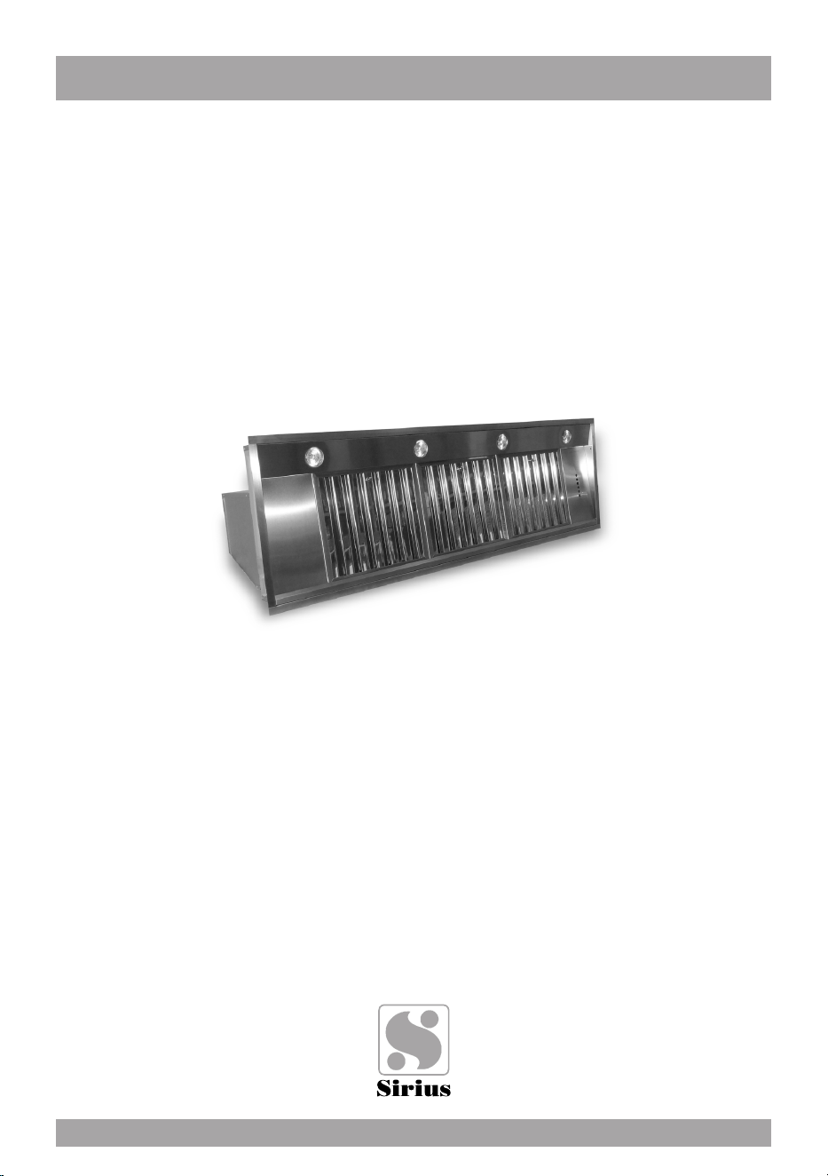
SU909
*** BEFORE INSTALLATION ***
ENSURE THERE IS NO VISIBLE OR HIDDEN DAMAGE SUSTAINED DURING SHIPPING
*** SHIPPING DAMAGE ***
MUST BE REPORTED WITHIN 5 DAYS OF RECEIPT
BUILT-IN RANGE HOODS
CARE AND USE MANUAL FOR:

2
1
1
2
1
1
2
1
1
2
1
1
2
1
1
2
1
1A
2
4 5
3
3
6 7
8
10
9
4
11

WARNING
Thank you for purchasing a Sirius Range Hood.
Please read all the instructions in this manual before
installing the appliance.
Save these instructions for future reference.
Only use this appliance as an exhaust ventilation system for the removal of coo-
king vapors. DO NOT use to expel ammable substances or any other materials
or vapors.
The installation procedures in this manual are intended for qualied installers, ser-
vice technicians or persons with similar qualied background.
DO NOT attempt to install this appliance yourself.
Ensure that electrical power is turned off at source before commencing installation.
All electrical wiring must be properly installed, insulated and grounded and conform
to all applicable codes and standards.
Make sure all existing duct work is clean of grease build up, or duct work should be
replaced, if necessary, to avoid the possibility of a grease re. Check all joints on
ductwork to ensure proper connection and all joints should be properly taped. Be
careful when cutting through ceilings or walls not to damage any hidden pipes or
electrical wiring. Ensure your kitchen has sufcient air return vents to replace the
exhausted air.
The minimum distance between the cooker surface and the inferior part of the co-
oker hood must be of 650 mm.
Fan ducts should always be vented to the outside of your home and never into
spaces within walls, ceilings, lofts or attics. Only use rigid, smooth steel for ducting.
The exhaust point of the blower requires a 6” round or 8” connection.
5

TABLE OF CONTENTS
BEFORE YOU BEGIN 7
DUCTING
External venting Requirements 7
ELECTRICAL
Electrical Supply 8
INSTALLATION
Installing 9
Re-Circulating Requirements 10
OPERATING PROCEDURES
General Advice 11
Functions 11
TECHNICAL DATA
Standard conguration 12
Generating a new transmission code 12
Learning the new transmission code 12
MAINTENANCE
Cleaning the Filter 14
Cleaning the Hood 14
Replace led lamp 14
WARRANTY 16
6
BEFORE YOU BEGIN: It is advisable to
test run the range hood before installa-
tion.
BEFORE STARTING – please read this
entire document and ensure you are fully
conversant with the requirements and limi-
tations. These units weigh approximately
125lbs and therefore require a minimum of
two people to install.
BEFORE YOU BEGIN
The manufacturer declines all responsibility
in the event of failure to observe the instruc-
tions given here for installation, maintenan-
ce and suitable operation of the product. The
manufacturer further declines all responsibi-
lity for injury due to negligence and the war-
ranty of the unit automatically expires due
to improper maintenance and/or installation.
Always fasten connections with sheet metal
screws and tape all joints with certied Silver
Tape or Duct Tape. Do not use screws to fa-
sten ductwork to the hood, only use tape as
the screws will stop the dampers from ope-
ning and your hood will not work. This hood
re-quires a 6” round or 8” duct outlet. You
can increase the duct size of the duct run
but never decrease it. Use the shortest and
most direct route possible. Always, where-
ver possible, reduce the number of transi-
tions and turns with as few sharp angles as
possible. Two staggered 45 degree angles
are better than one 90 degree. Make these
turns as far away from the motor exhaust as
possible, with as much space between each
bend.
DUCTING
(Not applicable if the range hood is used in
re-circulating mode).
WARNING: Do not vent this appliance into
any other ductwork, spaces between walls,
ceilings, attics, garages or any other con-
ned space.
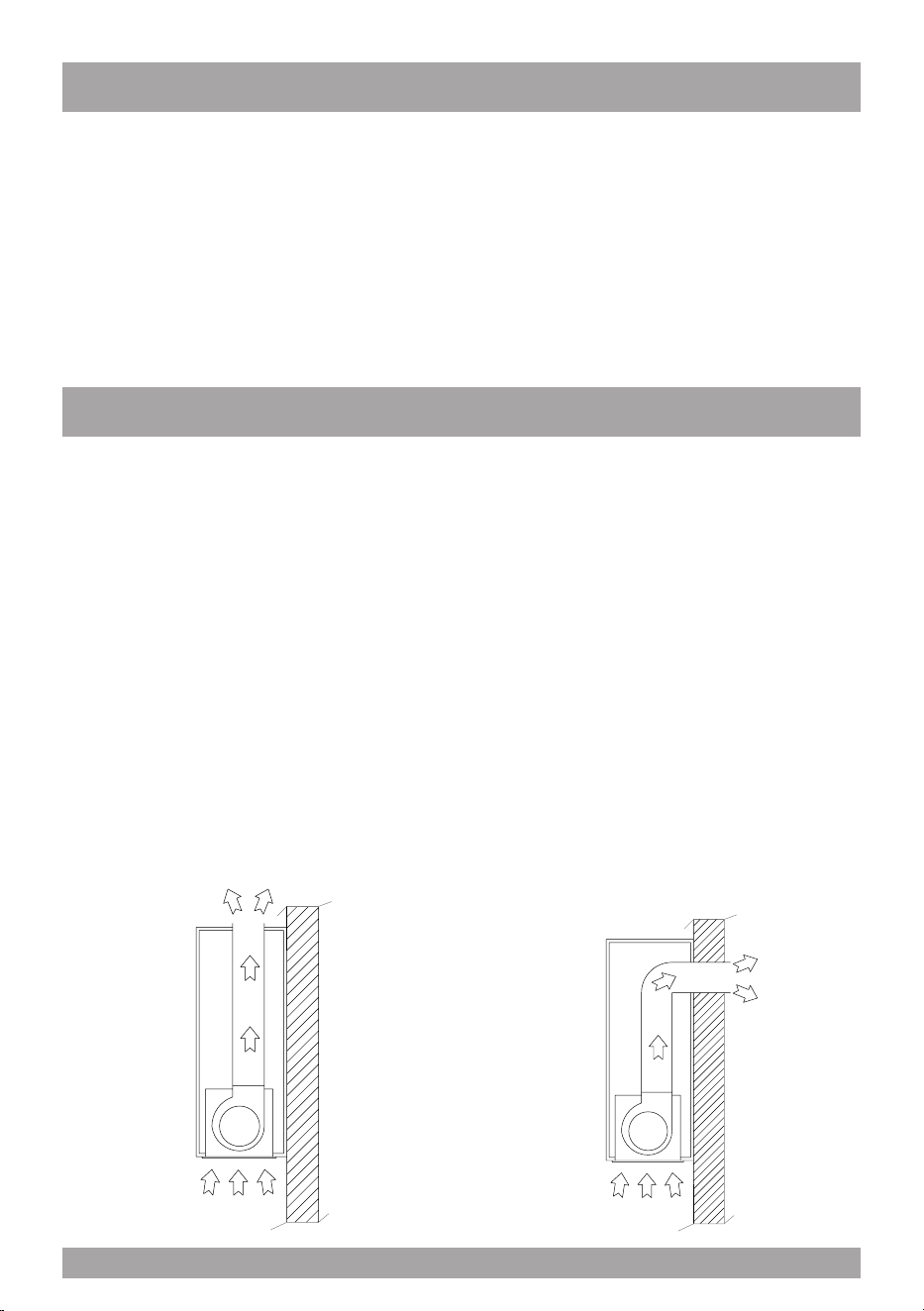
External Venting Requirements.
When planning new ductwork, always look
for the most direct route to the outside. Ven-
ting can be done through the roof or directly
through the back outside wall. (See Figure
12 and 13) Only use rigid type metal ducting
(plastic ducting is generally not permitted by
code). Flexible ducting could restrict airow
by up to 50%.
g. 12
g. 13
7

Electrical Supply.
This appliance requires 120V/60Hz, 3amp
electrical supply – ensure an appropriately
qualied person completes the electrical ho-
ok-up. The connection point for the electrical
supply is at the top of the unit, therefore the
electrical supply must be run down from the
ceiling alongside the ductwork.
All electrical and venting hook-ups must be in
place before commencing installation of the
hood-fan.
ELECTRICAL
WARNING: All electrical work must be
performed by a qualied electrician.
Please ensure that the appropriate electrical
codes or prevailing local building codes and
ordinances are adhered to.
Ensure that the electricity supply is discon-
nected at source. Do not use an extension
cord or adapter plug with this appliance.
This appliance must be grounded. Connect
to a properly grounded branch circuit, pro-
tected by a 15 amp circuit breaker.
8

INSTALLATION
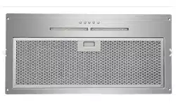
Installing SU909
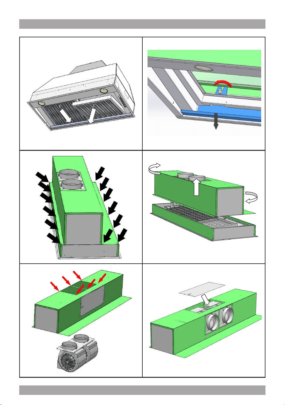
Before proceeding with the installation, in
order to avoid damage to the appliance, ple
ase remove the metallic grease lter.
To remove the metallic grease lter, use the
special handle and rotate down the lter, ta
king care to unhook it from its seat (g.1).
To remove the oil collector, loosen the two
screws as indicated in g. 1/A.
On the furniture make a hole with these di-
mensions:
SL909 Cm 140: 53”3/4 - 16”1/8 (1365mm x 410mm.)
SL909 Cm 86: 32”15/32 - 16”1/8 (825mm x 410mm.)
SL909 46”: 44”23/32 X 16 “1/8 (1136mm x 410mm.)
The range hood provides the air outlet on
up per side or alternatively on the rear side,
according to the needs of installation.
The standard arrangement of air outlet is on
the upper side, move it to the rear side of
product following these instructions:
Disconnect the electrical part of the motor,
re moving the electric connector.
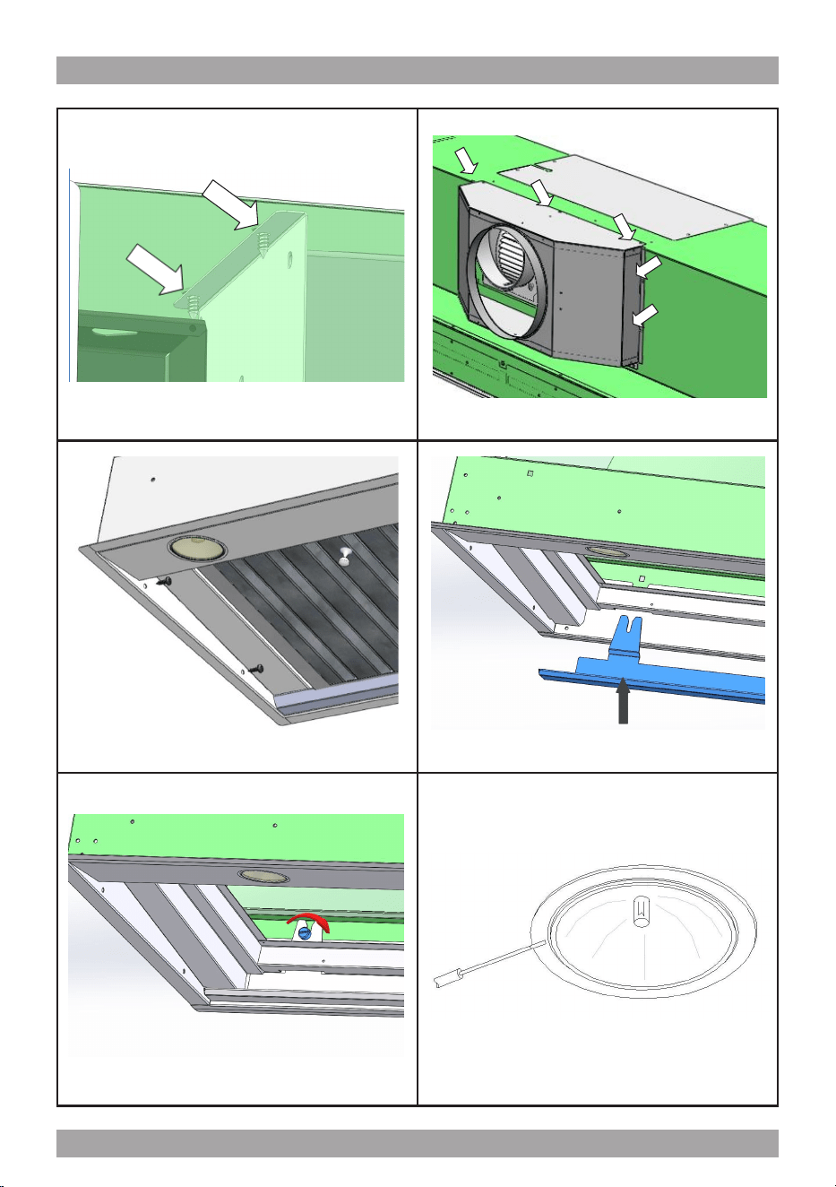
Move the product on a plain surface then
remove all the specic perimeter screws as
shown in g. 2, pick up the upper side as
shown in g. 3 and rotate it by 180°.
Remove all the six secure screws of the mo-
tors, extract the motors from the metal body
and move them into the specic side ope-
ning as indicated in g. 4 and g. 5.
The lid has to be moved on the upper side
as shown in g. 5.
To assemble the metal body put back on the
screws previously removed as shown in g. 2.
Pay close attention: they must correspond
to the blocking screws of the wiring system.
Make the electrical connection (g. 6).
Install the air outlet ange xing the screws
provided where the outputs of the two mo-
tors are (g. 7); this is not used in the one-
motor version and external motor (remote
motor) version.
Fix the product with the supplied screws as
shown on g. 8.
At this point take the oil collector and hook
it on the appropriate hole of the hood. Plea
se be careful not to scratch and damage the
product. (Fig. 9).
Fix the oil collector securing the pommels of
the range hood (Fig. 10).
Re-install the metallic grease lter previou
sly removed.
9
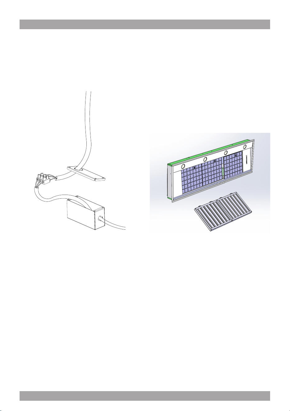
g. 14
CAUTION: Make sure the power is turned
off at source. Make electrical connections
(refer to Figure 14). Ensure that the plastic
aps at the exhaust outlet of the fan move
freely and have not become jammed or
stuck.
Connect the appropriate length of ducting to
the fan exhaust point and connect the duc-
ting to the exterior.
Do not x the ducting to the range hood
exhaust outlet with screws: use duct
tape. Use duct tape on all joints.
Re-Circulating Requirements.
If the unit is to be used in the recirculating
mode, t the carbon lters after the installa-
tion is completed (refer to Figure 15).
The carbon lter ts in behind the aluminium
grease lter. Ensure that the plastic tabs on
the carbon lter are facing outwards other-
wise it will be difcult to remove it later for
replacement.
A short length of ductwork must be con-
nected from the exhaust outlet on the fan
to wherever the air is to be exhausted.
Allow sufcient space to connect the duct-
work to the top of the exhaust outlet on the
fan housing. Do not x the ducting to the
range hood exhaust outlet with screws, use
duct tape. Duct tape should be used on all
joints.
g. 15
10
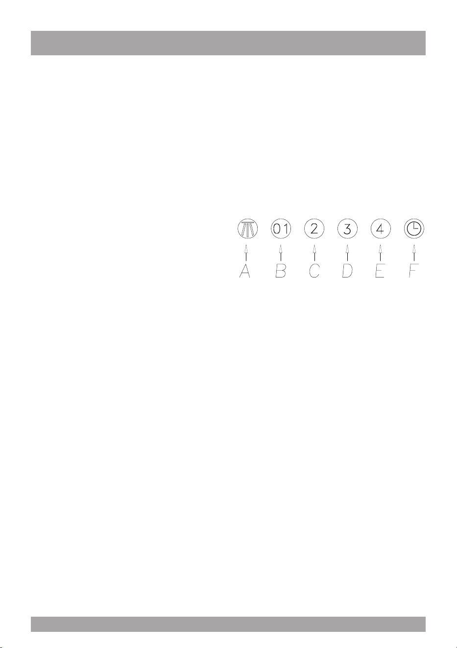
FUNCTION
SU909 (Fig. 16).
A: Light ON/OFF button
B: Blower Speed 1 (low) or OFF
C: Blower Speed 2 (medium)
D: Blower Speed 3 (high)
E: Blower Speed 4 (intensive)
F: 10 Minute Timer
OPERATING PROCEDURES
Read all the instructions before operating
the appliance. Save these instructions for
future reference.
General Advice.
Ensure that the grease lters are in place.
Without these components, operating blo-
wers could catch on to hair, ngers and lo-
ose clothing. Keep fan, lters and surfaces
free from grease and fat. Always turn the
hood fan ON when cooking. NEVER leave
cooking unattended.
NEVER dispose cigarette ashes, ignitable
substances or any foreign objects into blo-
wers.
Cooking that generates ame is not recom-
mended as this hood is equipped with a
thermal overload that will shut down the mo-
tor if it senses excessive heat. When frying,
oil in the pan can easily overheat and igni-
te. Heat oil slowly in an appropriately sized
pot (covering the entire burner) to reduce
the risk of boiling over and burning.
In the event of a range top grease re, ob-
serve the following:
Switch OFF the range hood. Turn off the
cook top then smother ames with a close
tting lid, cookie sheet or other metal tray. If
the ames do not go out immediately
EVACUATE AND CALL THE FIRE DE-
PARTMENT.
Never pick up a aming pan – you may be
burned. DO NOT USE WATER including
wet dishcloths or towels, as a violent steam
explosion may occur.
g. 16
Filter requires washing indicator: after 30
hours of use, all the buttons will light up to
remind you that the grease lter should be
cleaned. Follow the instructions for cleaning
lters in this booklet. Once the grease lters
have been cleaned and replaced, reset by
pressing the timer button (F). Do not rely so-
lely on this indicator. Generally, the grease
lter should be washed on a regular basis to
avoid grease lter res.
The blower should be turned on for appro-
ximately 5 minutes before cooking in order
to establish air currents upward through the
hood. Use the low speeds for normal use
and the higher speeds for strong odors and
fumes.
11
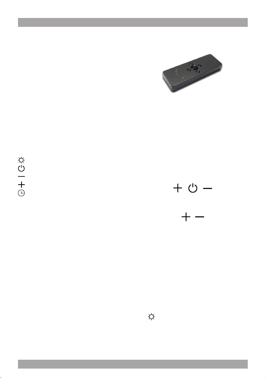
DEPENDING ON THE MODEL AVAILABLE
RC001
RADIO CONTROL
Radio control used for the remote operation of
ducted cooker hoods.
TECHNICAL DATA
- Alkaline battery powered: 12 V mod. 27A
- Operating frequency: 433.92 Mhz
- Combinations: 32.768
- Max. consumption: 25 mA
- Operating temperature: -20 ÷ + 55 °C
- Dimensions: 130x45x15 mm.
OPERATING DESCRIPTION
The transmitter is equipped with 5 buttons for coo-
ker hood management, as specied below:
: Light ON/OFF command.
: Motor ON (speed level 1) / OFF command.
: Reduce speed.
: Increase speed.
: 10-minute timer.
INITIAL OPERATING CONDITION
The manufacturer supplies the radio control unit
ready to be used with codes preset in the Factory
OPERATION MODE
Standard conguration:
Standard conguration requires all “cooker hoods
– radio control - system” to be provided with the
same transmission code. In the event two cooker
hoods – radio control system are installed in the
same room or nearby, each system may affect the
operation of the another. Therefore, the code of
one radio control system must be changed.
Generating a new transmission code:
The radio control system is provided with preset
codes. Should new codes be required, proceed
as follows: Press simultaneously buttons:
for two seconds. When Leds light on, press but-
tons:
(within 5 seconds). Leds ashing 3 times indicate
the procedure is completed.
WARNING! This operation deletes permanen-
tly the preset codes.
Learning the new transmission code:
Once the transmission code is changed in the ra-
dio control unit, the electronic central unit of the
cooker hood must be made to set the new code in
the fol- lowing way:
Press the main power-off button of the hood and
then restore power to the electronic control unit.
Within the next 15 seconds, press the Liight But-
ton to synchronise the central unit with the
code.
12
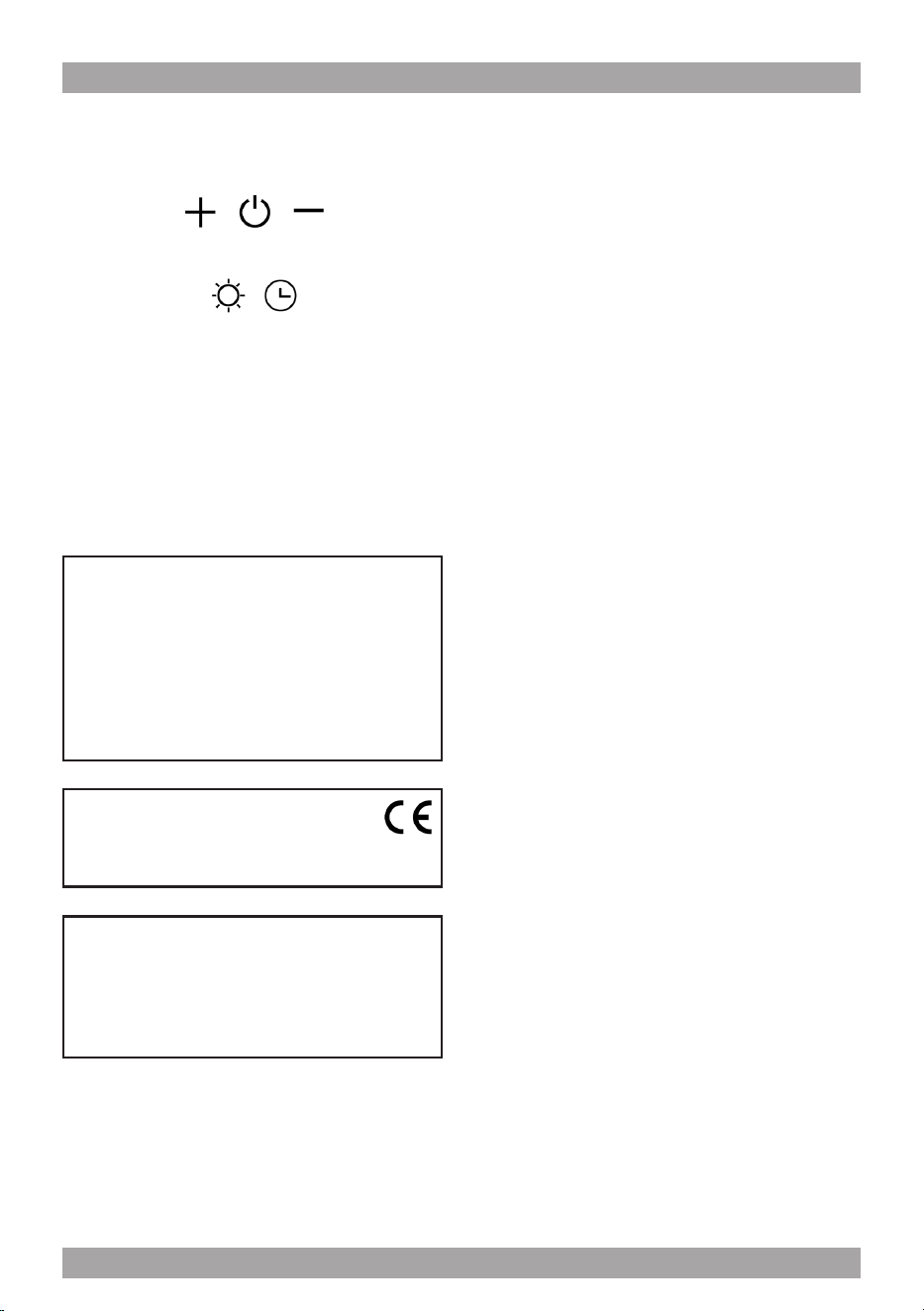
Reset of the Factory conguration:
To restore the Factory conguration, follow the
procedure described below: press simultaneously
buttons:
for 2 seconds. When Leds light on, press buttons:
(within 5 seconds). Leds ashing 6 times indicate
the procedure is completed.
WARNING! This operation deletes permanen-
tly the preset codes.
Emergency button:
In the event that the radio control does not work,
use the emergency button to switch the appliance
off. After any necessary repairs have been perfor-
med, reset the emergency button.
WARNING
The battery should be replaced every year to
guarantee the optimal range of the transmitter.
To replace the exhausted battery, take the pla-
stic lid off, remove the battery and replace it
with a new one, observing the correct battery
polarities.
Used batteries should be discarded in special
collection bins.
The below product:
RC001 Radiio Controll
complies with the specications set out in the
R&TTE Directive 99/5/EC.
WARNING
Any adjustments or modications which have
not been expressly approved by the holder of
the legal conformity certicate may invalidate
the user’s rights relating to the operation of
the device.
Rev. 0 26/08/14
The products are endowed with an electronic de-
vice which allows the automatic switching off after
4 hours working from the last operation.
Warning The battery should be replaced eve-
ry year to guarantee the optimal range of the
transmitter. To replace the exhausted battery,
take the plastic lid off, remove the battery and
replace it with a new one, observing the cor-
rect battery polarities. Used batteries should
be discarded in special collection bins.
Filter requires washing indicator: after 30 hours
of use, all the buttons will light up to remind you
that the grease lter should be cleaned. Follow
the instructions for cleaning lters in this booklet.
Once the grease lters have been cleaned and
replaced, reset by pressing the timer button (F).
Do not rely solely on this indicator. Generally, the
grease lter should be washed on a regular basis
to avoid grease lter res.
The blower should be turned on for approximately
5 minutes before cooking in order to establish air
currents upward through the hood. Use the low
speeds for normal use and the higher speeds for
strong odors and fumes.
13

MAINTENANCE
The hood-fan should provide many years of
trouble free service provided it is maintained
properly.
Cleaning the Filter.
Clean the grease lter either by carefully
hand washing, (so as not to damage the
lter design) or preferably in a dishwasher.
Depending on use, the lters should be cle-
aned at least every two weeks in a dishwa-
sher.
If a carbon lter has been tted this must be
replaced at least every 6 months as a mini-
mum. Depending on cooking style and na-
ture of cooking (greasy foods, fry’s, curries
etc) would probably require more frequent
replacement - if odors start to manifest
themselves when cooking it is time to repla-
ce the carbon lter. We suggest you retain
a spare set. These can be ordered from the
supplier of your range hood.
Cleaning the Hood.
Cleaning of the internal parts should be done
with a clean damp (not excessively wet) cloth
together with regular household detergent.
The external stainless steel elements should
be cleaned with a good quality foaming stain-
less steel cleaner. Read the manufacturers
directions. Generally they recommend that
the foam be sprayed onto a clean dry cloth
and then applied to the stainless steel. Allow
the foam to react on the surface for a few mi-
nutes and then wipe with a clean dry cloth.
It is advisable to clean the surfaces that are
exposed directly to heat from the cook-top on
a regular basis, to prevent the marks from be-
coming baked on.
Do not under any circumstances use an
abrasive type cleaner as this will scratch and
damage the stainless steel nish. Glass com-
ponents should be cleaned with a product
such as Windex.
Replace led lamp
To replace the led lamp, remove the lamp
(Fig. 11) inserting a screwdriver or another
sharp tool between the lamp and its chro-
me support and replace it with a lamp of the
same kind.
14

15

Three Year Limited Warranty
YOU MUST REGISTER THE PURCHASE OF YOUR PRODUCT ON LINE AT
www.siriuscappe.com/usa/warranty.htm TO CONVALIDATE YOUR WARRANTY.
YOU CAN FIND THE DATA OF YOUR HOODS ON A LABEL INSIDE THE HOOD. JUST REMOVE
THE GREASE FILTER TO READ IT.
Sirius S.P.A.
Zona industriale Berbentina 6/A
60041 SASSOFERRATO (AN)
ITALY
Sirius after sale service
Telephone (toll free): 1-877-474-8770
Email: Sirius@adcoservice.com
Register Online! www.siriuscappe.com/usa/warranty.htm
WARRANTY SERVICE
To qualify for warranty service, you must notify Sirius After sale service at the email address
stated below or call toll free USA 1-877-474-8770 and provide the model number, description
of the fault or defect and original date of purchase. Sirius reserves the right to request proof
of original purchase. Sirius will at its sole option and discretion replace products that arrive
damaged through shipping, provided shipping damage is reported as stated above WITHIN 5
BUSINESS DAYS OF RECEIPT of the shipped product or products.
ONE YEAR SERVICE REPAIR WARRANTY:
During the rst year from date of original purchase, Sirius will, at its option, repair or replace, without
charge, any product or part which is found to be defective under normal use and service.
THREE YEAR PARTS WARRANTY:
For three years from date of purchase, Sirius will provide free of charge, non-consumable replacement
parts which are found to be defective under normal use and service.
WHO IS COVERED:
Sirius warrants to the original consumer purchaser of its products that such products will be free from
defects in materials and workmanship for a period of three years from the original date of purchase.
There are no other warranties, express or implied, including, but not limited to, implied warranties of
merchantability or tness for a particular purpose or application.
WHAT IS NOT COVERED:
This warranty does not extend to lters, lamps, batteries, ducts and ductwork components. This war-
ranty does not cover normal maintenance and service or products or parts which have been subject to
misuse, negligence, accident, improper maintenance or repair, faulty installation or installation contrary
to recommended installation instructions. The warranty on glass screens is limited to manufacturing
defects only and expressly excludes cracks and breakages as a result of faulty installation.
Labor and
associated costs associated directly with removal and re-installation are expressly excluded.
The duration of any implied warranty is limited to the three year period as specied for the express
warranty. Some states and provinces do not allow limitation on how long an implied warranty lasts, so
the above limitation may not apply to you.
90007011909 - MM 06/19