User manual
Core
Core
Introduction
- Other resources
- Important safety information
Core 5, 7, 47, 59 monitors,
Core Sub and Core Sub Compact
- Amplier
Monitor orientation
- Core 59 and Dynaudio Orbit Bafe
- Rotating the Core 59’s Orbit Bafe
Connecting the monitors
- Mains
- Standby mode
- Audio signals
- Word Clock Input
Adjusting the volume
- “Max input level” switch
- SPL at 1 m -20 dBFS
- SPL Settings for all models
Front LED Indicator
DSP Settings
- “Bass extension” switch
- “Bandwidth” switch
- “Sound balance” switch
- “Position” switch 1:
“Anechoic” / “Desk” / “Soft”
- “Position” switch 2:
“Free” / “Wall” / “Corner”
Updating the rmware
- Core Update Tool
- USB 2.0 connection
- Firmware update process
Replacing drivers
- Core Update Tool - Maintenance

Introduction
Welcome and congratulations on your purchase of
Dynaudio Pro Reference Monitors.
Each monitor is constructed by Dynaudio in Denmark to meet
only the highest standards. These monitors are a key part of your
monitoring system, but remember that monitor performance is also
affected by how they are placed in your room.
Spend the necessary time on placing and tuning your new monitors
just right and your audio will be reproduced with great accuracy.
Please follow the instructions carefully to get the very best
performance from your new Dynaudio Pro monitors.
When your monitors are installed properly and the rear panel settings
are adjusted to t your acoustic environment, your mixes will translate
effortlessly to other playback systems – including cinemas, home
theatres, car stereos, and headphones.
Other resources
Please also visit our website dynaudio.com/support.
Here, you will nd additional information including:
X Q&A’s on Dynaudio products and technical information
X Dynaudio events and news
Important safety information
A separate “Important safety instructions” document is also
included with the product. Please make sure to read it carefully
before operating your new monitors.
Core 5, 7, 47, 59 monitors, Core Sub and Core
Sub Compact
The transducers of your Dynaudio Core monitor will achieve a better
sound quality after a break-in period.
Especially after the rst hours of use, you may notice a signicant
increase in sound quality, and further subtle improvements in
subsequent hours of use.
Amplier
The Core monitor range features integrated Class-D ampliers with
analogue and digital inputs. All connections and settings are available
on the back plate of the amplier. Please do not remove the amplier
yourself. In case of service, contact your Dynaudio reseller.
Note
If you have either a Core 7, Core 47, Core 59, or Core Sub
with version 1.0 rmware, please refer to that manual found here.
Otherwise, you can update the Core rmware to the latest version
using the Firmware Update procedure found in this document.
Once you have updated the rmware on these models, the SPL
settings will be different than the original labelling.
For the Core Sub, the “Attenuation” settings will also be different
from their original labels.
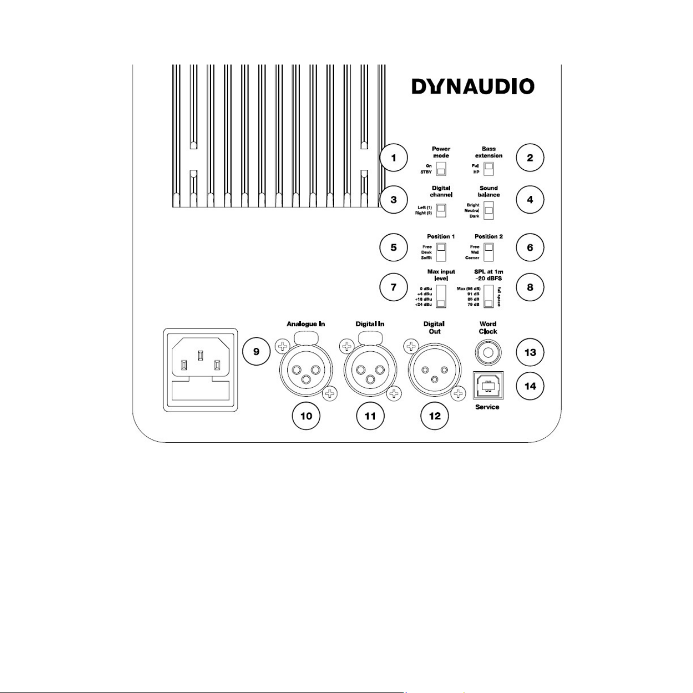
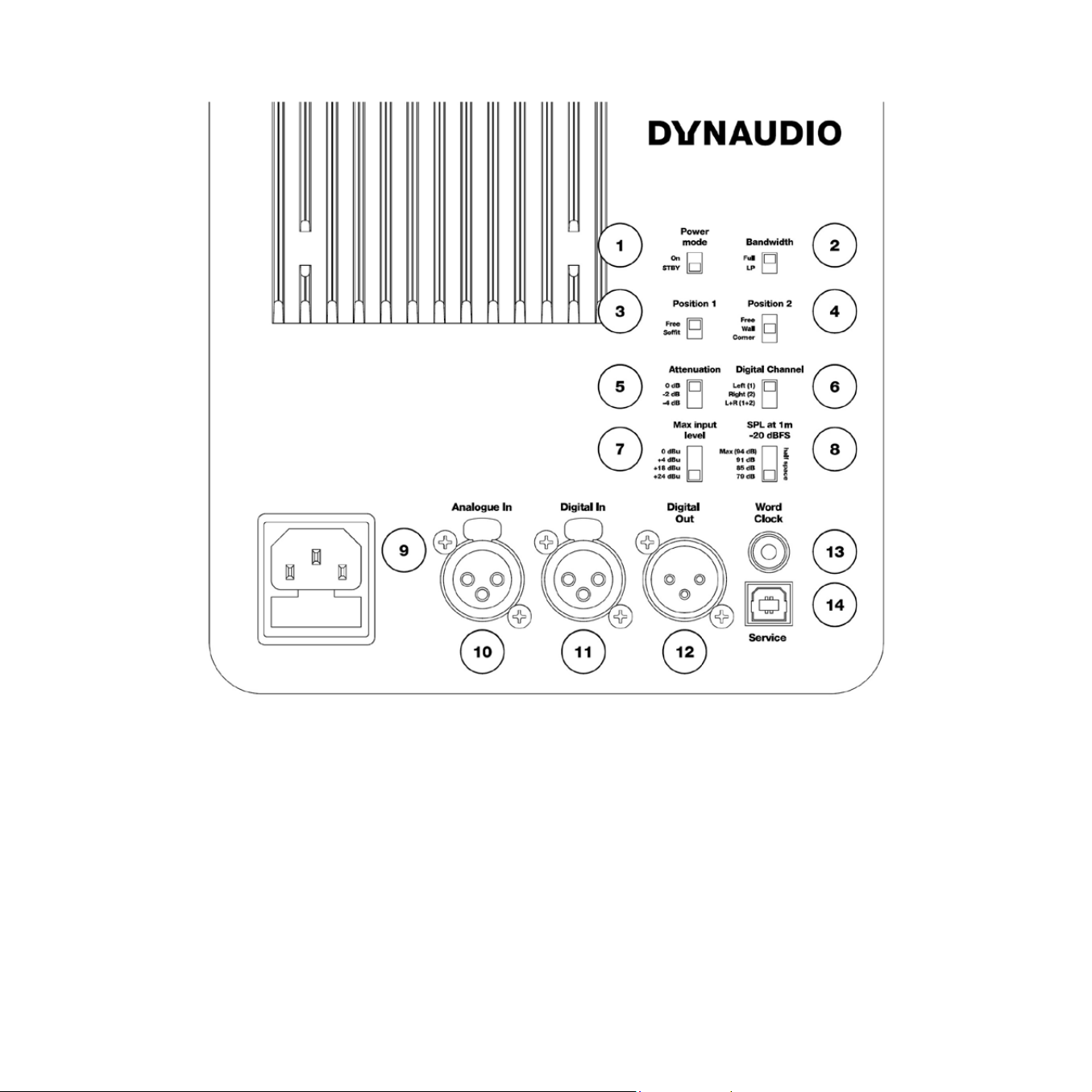
1. “Power mode”: Power-saving auto-standby switch
2. “Bass extension”: sets a Linkwitz-Riley HPF at 80Hz
3. “Digital channel”: selects the left or right channel of the
AES digital input signal
4. “Sound balance”: switches between three tilt lter settings
5. “Position” switch 1: position lters
6. “Position” switch 2: boundary lters
7. “Max input level”: sets the maximum input voltage.
This switch is labelled “Analogue input sensitivity” on some
models.
8. “SPL at 1 m -20 dBFS”: sets the SPL for -20 dBFS
(-20 dBu from selected maximum input voltage or -20 dBFS from
AES input). This switch is labelled “SPL level” on some models.
9. AC power Input (100-240 V)
10. “Analogue in”: Balanced analogue input (XLR)
11. “Digital In”: AES digital input (XLR)
12. “Digital Out”: AES digital output – pass through for second
monitor (XLR)
13. “Word Clock”: Word Clock input (75 Ω BNC)
14. “Service”: USB Type B for rmware update or service
1. “Power mode”: Power-saving auto-standby switch
2. “Bandwidth”: sets a Linkwitz-Riley LPF at 80Hz
3. “Position” switch 1: position lters
4. “Position” switch 2: boundary lters
5. “Attenuation”: for use with two or four subwoofers
6. “Digital channel”: selects the left, right, or left + right
channels of the AES digital input signal
7. “Max input level”: sets the maximum input voltage.
This switch is labelled “Analogue input sensitivity” on some
models.
8. “SPL at 1 m -20 dBFS”: sets the SPL for -20 dBFS
(-20 dBu from selected maximum input voltage or -20 dBFS
from AES input).
9. AC power Input (100-240 V)
10. “Analogue in”: Balanced analogue input (XLR)
11. “Digital In”: AES digital input (XLR)
12. “Digital Out”: AES digital output – pass through for second
monitor (XLR)
13. “Word Clock”: Word Clock input (75 Ω BNC)
14. “Service”: USB Type B for rmware update or service
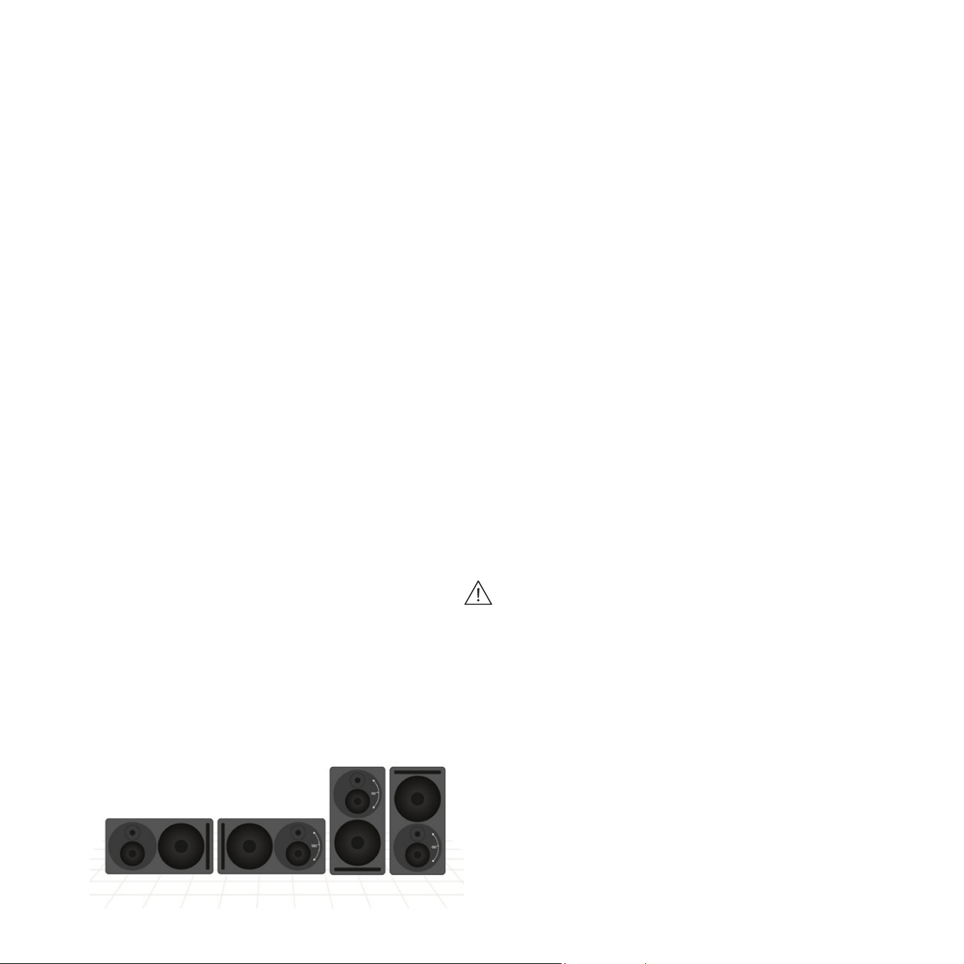
Monitor orientation
The Core monitors give you the advantage of multiple orientations
for each monitor, offering maximum exibility for proper installation.
Core monitors can be placed standing up or on their sides with
either the woofers facing out or in. They can also be placed with the
woofer on top in case that aligns the tweeter better with the listener’s
ear height or improves the bass response of the room.
Note that the Core 47 has two models with the woofer placed on
either side of the tweeter/midrange assembly. These monitors should
be used in horizontal orientation only.
Core 59 and Dynaudio Orbit Bafe
The Core 59 offers additional benets, as it incorporates our Orbit
Bafe (formerly “221”) that was rst used in the renowned Air series
of monitors.
This technology places the tweeter and midrange driver together in
their own self-contained bafe/enclosure that can be rotated inside
the larger cabinet to provide additional orientation options.
For example, you may turn the midrange and tweeter assembly 90
degrees in either direction to place the monitor on its side and still
have proper time alignment from the tweeter and midrange drivers.
For a centre channel monitor, you can position the woofer either
below or above the Orbit Bafe for the least obstructive path to the
listener. There is no need for separate left, centre, and right channel
models as each monitor is capable of operating in any position of a
5.1, 7.1, 9.1.2, or Dolby Atmos surround monitor system.
Rotating the Core 59’s Orbit Bafe
See Appendix.
Connecting the monitors
Mains
Ensure that you have the correct three-wire grounding type mains
cable for your region. The power supplies in the monitors have
switching inputs that automatically adapts to the incoming voltage
depending on your location.
Plug in the provided mains cable to the monitor and then to the
outlet. Ensure the monitor powers up correctly by checking that the
power LED is lit on the front of the monitor. Once this is conrmed,
power off the monitor by removing the mains cable from the outlet
before connecting audio signals.
Standby mode
The monitors have a standby mode that helps conserve energy
when they are not in use.
X When the “Power mode” switch is set to “ON”, the monitors
remain powered on until the mains cable is unplugged.
X When the “Power mode” switch is set to “STBY”, the monitors will
automatically enter a power-saving standby mode when not in use
for 20 minutes and shut down the amplier section until audio is
once again detected at the input.
Note
To comply with the European Commission Regulation (EU) No 801/
2013 (low standby directive) the “Power mode” switch must always
be set to “STBY”.

Audio signals
There are two physical inputs you can choose between:
X XLR balanced or unbalanced
X XLR AES Digital
Word Clock Input
When using the AES digital input, you may synchronise the digital
clock using a word clock signal. The Word Clock connector on the
Core monitor should be used in this case to receive a word clock
signal that is derived from the AES audio source. This will ensure
that the internal clock of the Core monitor is running exactly in sync
with the AES audio signal source.
If no word clock signal is present at the Core’s Word Clock input, the
Core monitor will use the embedded word clock from the AES signal
itself as a synchronisation source. If the word clock signal is present,
but not in sync with the AES clock, the front panel LED will ash
bright green and the monitors will mute.
If you are using the Core Sub or Core Sub Compact to extend
the frequency response of a single Core monitor, connect the same
audio source to both the Core Sub and Core monitor either with the
analogue or AES inputs. For the analogue inputs, you will need to
use a professional balanced line splitter to feed both the Core Sub
and Core monitor analogue inputs.
If using the digital inputs, you can simply daisy-chain the monitors
using the digital out connector. Ensure that both the monitor and sub
are set to the correct digital channel (L, R, or L + R).
Caution
Before sending audio to the monitors, set the Analogue input
sensitivity to 24 dBu and the “SPL at 1 m -20 dBFS” switch to
lowest setting. Then adjust the outputs of your mixer or audio
interface to a low setting and gradually turn up the signal until
you get a reasonable volume. This will prevent any accidental
overload of the monitor input.
Adjusting the volume
The Core monitors have two inputs – analogue and digital.
When using the analogue input, adjust the “Max input level” switch
to optimize the gain staging between your analogue audio interface
and the monitor. Then you can choose the maximum output level for a
-20 dBu signal with the “SPL at 1 m -20 dBFS” switch. When using
the digital input, the “Max input level” switch has no effect.
Note
The “SPL at 1 m -20 dBFS” switch setting affects acoustic output
level of the monitor regardless of which input you utilise.
“Max input level” switch
This switch is labelled “Analogue input sensitivity” on some models.
There is a four-position switch that adjusts the analogue input
sensitivity for the monitor. Depending on the maximum output level
of your mixer, interface, or monitor control system, you can choose a
setting that optimises the gain staging into the monitor.
For example, if you are using a professional audio interface or console
with a max output of +24 dBu, set the input sensitivity to +24 dBu.
If you are using a prosumer type mixer or interface with a maximum
output of +18 dBu, then set the input sensitivity to +18 dBu.
For consumer equipment such as DJ mixers that operate at a nominal
level of -10 dBV, set the input sensitivity to 0 dBu.
0 dBu is the loudest setting while +24 dBu is the softest setting.
The range is provided to optimise the signal to noise ratio between
the monitoring output and the monitor.
SPL at 1 m -20 dBFS
The “SPL at 1 m -20 dBFS” setting determines the volume the
monitors will achieve for an input level of -20 dBFS or -20 dBu from
the selected “Max input level” setting as measured 1 meter from
the monitor. If you work primarily at low levels, you can use a lower
SPL setting to optimise the gain staging of the monitor to achieve
the best results. If you work at louder levels, use the maximum SPL
setting for the greatest volume that the monitor can provide.

When working in a calibrated environment such as Dolby Atmos,
these settings are designed to provide a reference level at 1 meter
distance with +20 dBu of headroom available. A typical setup would
select the 85 dBSPL for all monitors at the same distance from the
listening position.
Note
Notice that the max “SPL at 1 m -20 dBFS” setting is different for
each Core model. However, all Core monitors and subs have the
calibrated settings for 85 and 91 dBSPL so that large arrays of
monitors can share a common reference.
SPL Settings for all models
X Core 5: 79, 85, 91, 96
X Core 7: 85, 91, 96, 101
X Core 47: 85, 91, 96, 105
X Core 59: 85, 91, 96, 105
X Core Sub: 85, 91, 96, 102
X Core Sub Compact: 79, 85, 91, 94
Some models may have different values listed. Update to the latest
rmware version 1.1 to use these values.
Note
SPL settings for the Core Sub and Core Sub Compact are for half
space as they typically are placed on the oor. You can also use the
“SPL at 1 m -20 dBFS” setting in combination with the “Attenuation”
setting to achieve more subwoofer sensitivity adjustments as needed
for multiple subwoofers and/or room placement.
Front LED Indicator
There is one LED indicator on the front that provides information on
the status of the Core monitor by glowing or ashing either green or
red. The following modes are indicated in this way.
X Standby: The LED turns bright red then fades to 50% after 5
seconds.
X Power On: The LED turns bright green then fades to 50% after 5
seconds.
X Input Clipping: The LED flashes orange when the analogue to
digital converter is clipping.
X Thermal Protection: The LED pulses red and the output is reduced
by 6 dB.
X Word Clock Error: When the word clock input is not aligned
with the AES input signal, the LED flashes bright green and the
monitors are muted.
DSP Settings
Our engineers have created a DSP controller for these monitors that
lets you tailor the sound to your particular environment.
The DSP settings provide precision adjustments that optimise the
monitors for their position and mounting within the listening space.
“Bass extension” switch
The Core series monitors are designed to handle deep bass by
themselves. And under normal conditions, the “Bass extension”
switch should be set to “Full”. However, if you are integrating a
Core Sub or Core Sub Compact to extend the bass response
even further, set the “Bass extension” switch to “HP”. This will
engage a 4th order Linkwitz-Riley high pass lter at 80 Hz with time
alignment that properly integrates the monitor with the Core Sub/
Core Sub Compact.
“Bandwidth” switch (Core Sub or Core Sub Compact)
Use the “LP” setting when integrating a Core Sub or Core Sub
Compact to extend the LF response of a Core Monitor.
This will engage a 4th order Linkwitz-Riley low pass lter at 80 Hz
to integrate the Core Sub or Core Sub Compact with the Core
monitor.
“Sound balance” switch
The sound balance, or tilt lter, represents a rened way to affect
the overall tone of the monitor (not applicable for the Core Sub or
Core Sub Compact). Depending on the room treatment and other
factors, it may be necessary to make the monitor darker or brighter
than the neutral setting. A dead sounding room with a great deal of
treatment might need a brighter setting than a lively room with many
reective surfaces. Musical styles and program material may also
affect the choice of sound balance as well as personal preference.

The “Sound Balance” switch offers three settings:
X “Bright”: 20 Hz -1.5 dB, 20 kHz +1.5 dB
X “Neutral”
X “Dark”: 20 Hz +1.5 dB, 20 kHz -1.5 dB
What this lter actually does is to tilt the entire spectrum by 1.5 dB
at either end, using minimal phase lter to either brighten or darken
the overall response. This minimal lter alters the tonality without
inducing audible phase anomalies, thereby maximising the linearity
of the monitor.
“Position” switch 1: “Anechoic” / “Desk” / “Soft”
Depending upon where your Core monitors are positioned in
your room, you can adjust the Core’s DSP to optimise for differing
acoustics.
X The “Anechoic” setting is used when the monitors are placed on
monitor stands in rooms that have sufcient dampening treatment
such as recording studios and lm dubbing stages.
X The “Desk” setting is used when the monitors are placed on a
workstation or meter bridge of a mixing console (not applicable
for Core Sub or Core Sub Compact).
X The “Soffit” setting is used when the monitors are mounted in
properly designed wall soffits as part of an overall architectural
acoustic design.
“Position” switch 2: “Free” / “Wall” / “Corner”
Boundary lters controlled with the second Position switch are
used to compensate for monitors that are placed close to walls or
in corners where low-frequency room modes can be triggered by
the monitor. The Core’s DSP can adjust the response to compensate
for either a wall or corner placement.
X If your monitors are placed further than 50 cm from any wall
surface, use the “Free” setting.
X If you have positioned your monitors within 50 cm of a wall,
“Position” switch 2 should be set to “Wall”.
X If the monitor is placed within 50 cm of a corner, set “Position”
switch 2 to “Corner.”
These settings will help coping with anomalies created by reections
coming off the back and sidewalls, especially in the lower frequencies.
Updating the rmware
Core Update Tool
Periodically you may need to update the rmware in your Core
monitors. This is done using the Core Update Tool and rmware
download found here: Core Series downloads. The download
packages include software for both macOS and Windows along
with rmware les.
X Download and extract the ZIP file. Inside the folder you will find
two applications, one for Mac and another for Windows along
with the rmware les.
X Place the application in the appropriate location for your computer.
USB 2.0 connection
You will also need a USB 2.0 connection between your computer
and the Core monitor in order to update the rmware. Each Core
monitor has a female USB type B connector on the back panel.
Firmware update process
X To update the firmware, first ensure that the Core monitor is
turned on.
X Connect your computer and the USB jack on the monitor’s back
panel using a USB cable.
X Launch the Core Update Tool.
Caution
You may have to change your security preferences to allow the Core
Update Tool to run on your computer.
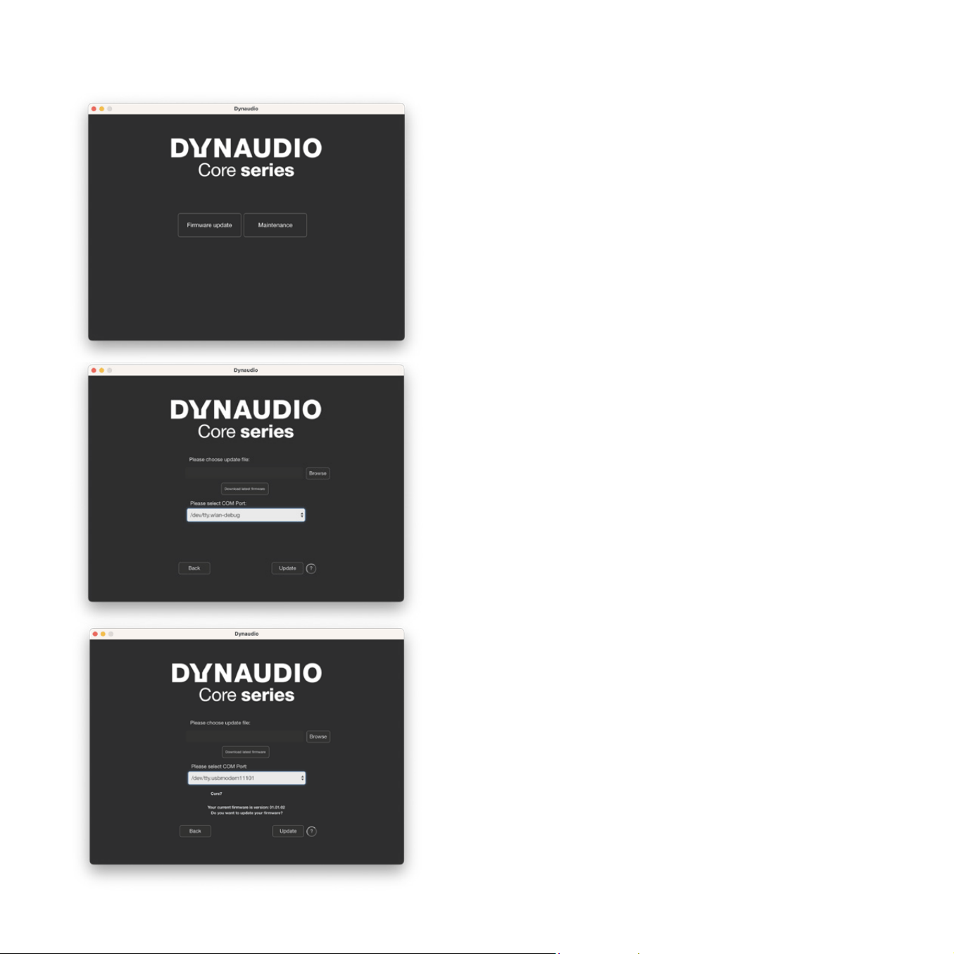
1. Choose the “Firmware update” option, and you will see this
window:
2. Choose the COM port that is connected to the Core monitor.
As port names may be random and not obvious, try selecting
each one until you see that a Core monitor is recognised. You will
see the Core model displayed along with the current version
number of rmware that is installed.
3. Next, browse to the location of the downloaded rmware les by
clicking the ‘Browse’ or click the button to download the latest
rmware.
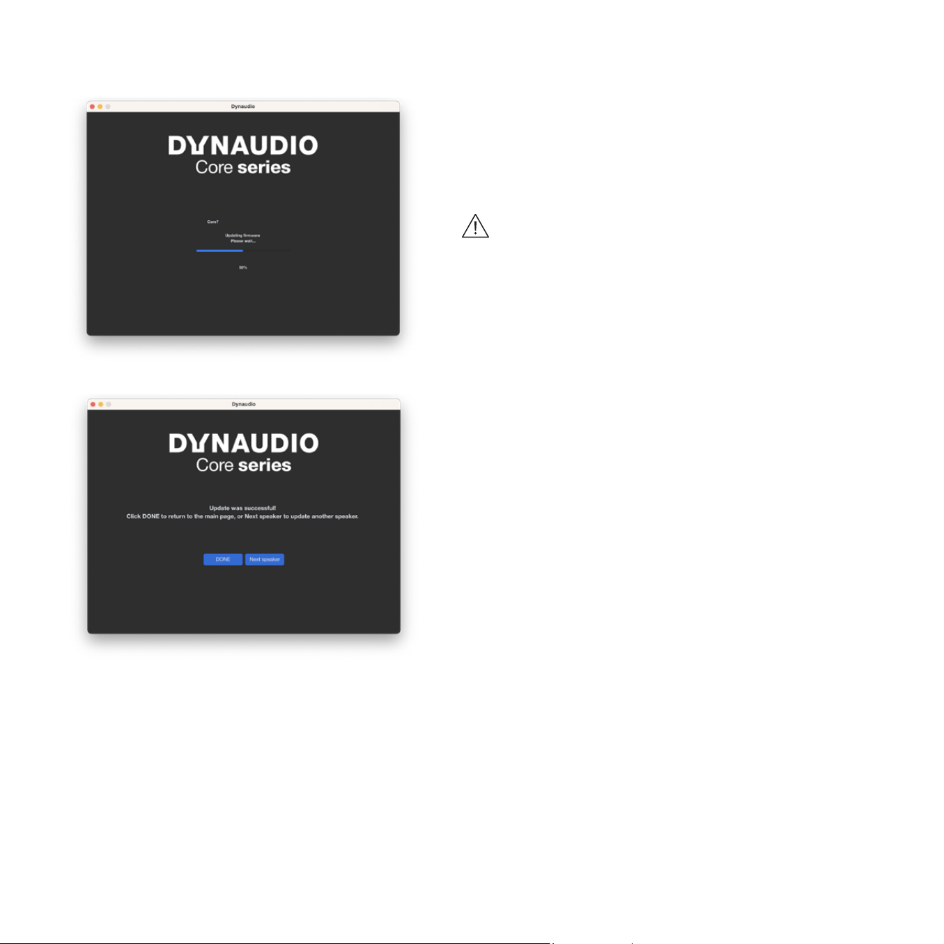
4. Once you have a proper rmware le selected, click the Update
button. A progress bar will appear showing the status of the
upload. Once the upload has nished, you can either continue to
update additional speakers or click DONE, disconnect the USB
cable, and your Core monitor is ready to use.
Caution
To ensure proper operation, use the same rmware le in each
speaker of your system. In the case that you are only updating
one speaker, rst check to see what rmware is installed on the
other speakers in the system and load that rmware le when
updating. It is recommended that you update all speakers and
subs in your system to the latest rmware when possible.
6. The update is done.
Replacing Drivers
Core Update Tool - Maintenance
Should you need to replace a driver in your Core speaker, it will be
necessary to calibrate the speaker for optimal performance.
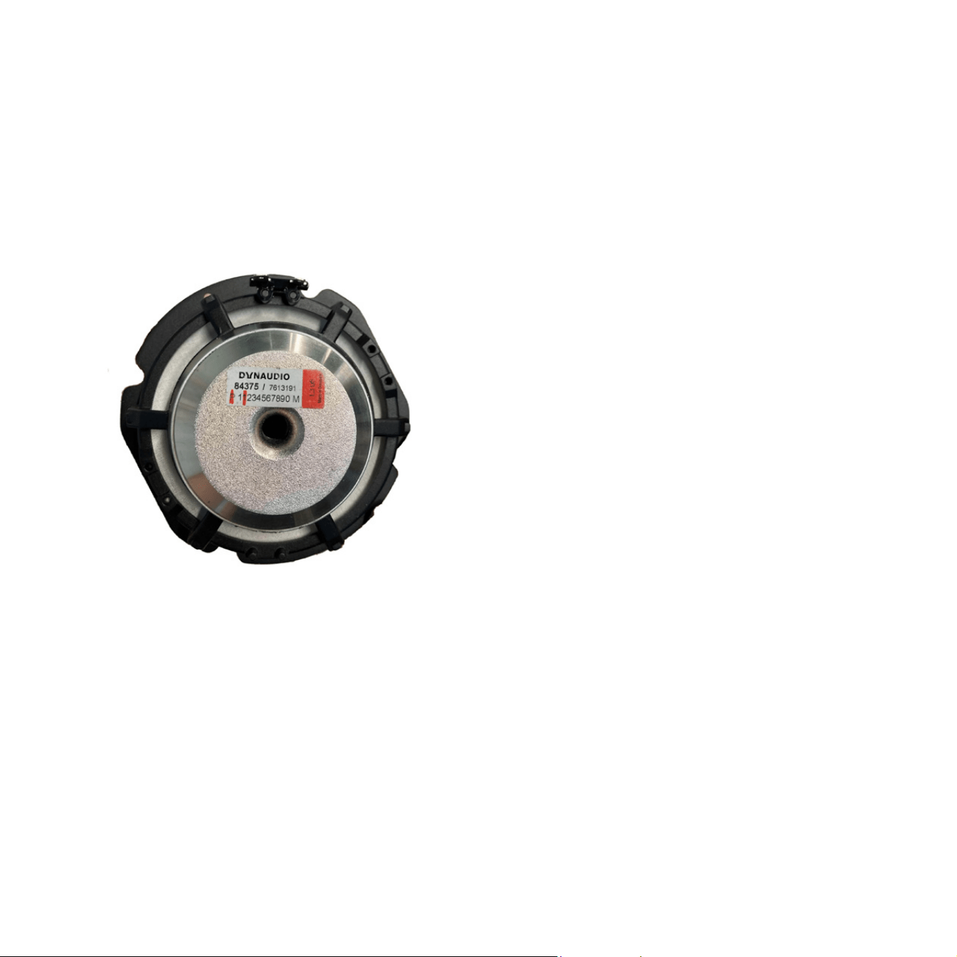
Each Dynaudio driver is calibrated at the factory and marked with
values on the driver assembly. Before installing the driver in the
speaker cabinet, make note of this value.
In the photo above, the characters marked in red are the calibration
value, in this case ‘P1’. Once you have this value noted, complete
the driver installation and launch the Core Update Tool. Make sure
the Core speaker is powered on and connected via the USB port.
Click the ‘Maintenance’ button and select the appropriate COM port.
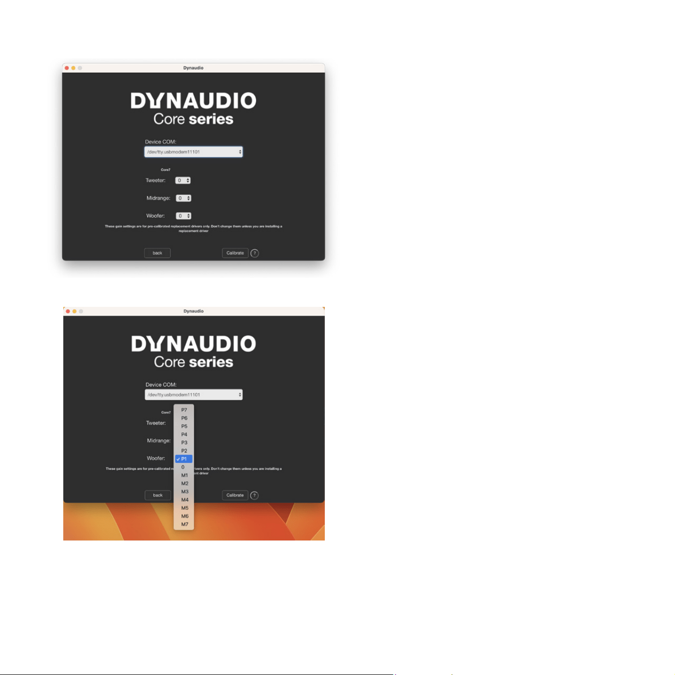
The Core model will be identied and the calibration will automatically
update to the original values for each driver. Now enter the new value
for just the replacement driver. In this example, the driver is being set
to ‘P1’.
Once you have entered the value, press the ‘Calibrate’ button to
upload it and your Core speaker is now ready to use.
For two-way speakers, Core 5 and Core 7, ignore the midrange
setting.
For Core Sub, the ‘Midrange’ is for the bottom pair of drivers and the
‘Woofer’ is for the top pair of drivers. An average calibration level of
both drivers in the pair should be used. (P1 = +1 and M1 = -1)
For the Core Sub Compact, the ‘Tweeter’ is for the left side driver
and the ‘Woofer’ is for the right side driver as seen from the front.

Dynaudio A/S
8660 Skanderborg
Denmark
User manual, Core, 2025
All text and image copyrights reserved.
Subject to change without notice.