12 1
KBP ECO2S, ECO2S+, and PlatinumX unit heaters are to be operated at voltage listed on the rating label. It is important that you verify the power
supply voltage is the same as the nameplate voltage of the heater. Connecting the heater to an improper voltage or failure to follow the procedures as
outlined in this manual can result in damage to the heater and void the warranty. This heater is provided with a factory installed thermostat. Disconnect
all power from the heater at the main service panel before attempting to install or service this unit. All electrical wiring must conform to local electrical
codes. Heater circuit must be properly protected.
SAVE THESE INSTRUCTIONS
INSTALLATION AND MAINTENANCE
DANGER
!
!
ELECTRIC SHOCK OR FIRE HAZARD
READ ALL WIRE SIZING, VOLTAGE REQUIREMENTS AND SAFETY DATA TO
AVOID PROPERTY DAMAGE AND PERSONAL INJURY
WARNING
!
!
KING ELECTRIC MFG CO · 9131 10TH AVENUE SOUTH · SEATTLE, WA 98108 · PH:206 762 0400 · FAX: 206 763 7738 · www.king-electric.com
READ CAREFULLY - Use the heater only as described in this manual. Any other use is not recommended and could result in fire, electric shock,
and personal injury. Following these instructions will prevent difficulties that might occur during the installation and use of the heater. Please
study the instructions first, as they may save considerable time and trouble during use addition to providing important safety information. Make
sure to save these instructions for future use.
Read all instructions before wiring or using this heater.
Heaters outlet grill is very hot when in use. To avoid burns, do not touch hot surfaces with bare skin. Keep combustible materials, including furniture, pillows,
bedding, papers, clothes, curtains, and boxes at least 3 feet from the front of the heater and keep them away from the sides and rear.
Do not use outdoors.
Heater is not intended for use in bathrooms, laundry areas or similar indoor locations. Never locate heater where it may fall into a bathtub or other water container.
Do not insert or allow foreign objects to enter any inlet or outlet openings as this may cause an electric shock, fire, or damage to the heater.
To prevent a possible of fire, do not block air intakes or exhaust in any manner.
Heater has hot surfaces. Internal thermostat and limiting parts can arc or create sparks inside. Do not use this heater in areas where gasoline, paint,
or flammable liquids or gases are used or stored.
Use this heater only as described in this manual. Any other use is not recommended by the manufacturer and may cause fire, electric shock, explosion or injury
to people and or property.
If heater shows signs of overheating immediately turn the circuit breaker off to the heater. Remove and inspect for any objects on or adjacent to the heater that may
cause the high temperatures. Have a professional inspect the internals until the reason is clear why the heater is overheating. Do not reinstall until it has been
professionally serviced.
Do not operate heater after it malfunctions. Disconnect heater at service panel and have heater inspected by a reputable electrician before reusing.
To disconnect heater, turn controls to off position, and turn off power to heater circuit at main electrical panel or operate internal disconnect switch to off if provided.
Extreme caution is necessary when any heater is used by or near children or invalids and whenever the heater is left operating and unattended too.
!
WARNING
!
WARNING
!
WARNING
!
WARNING
!
WARNING
!
WARNING
!
WARNING
!
WARNING
!
WARNING
!
WARNING
Do not install bottom of heater less than 6 ft above
the floor 6 inches to side wall, 5 inches to back wall,
and 2 inches to ceiling when clearance to ceiling is 2
inches. Do not point heater at ceiling.
108017- Rev.10.3.25
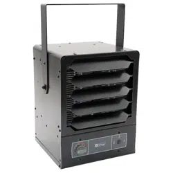
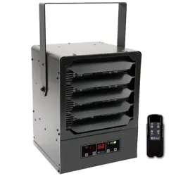
KBP
Electronic Unit Heater
KBP
KBP
SAVE THESE INSTRUCTIONS
KING ELECTRIC MFG CO · 9131 10TH AVENUE SOUTH · SEATTLE, WA 98108 · PH:206 762 0400 · FAX: 206 763 7738 · www.king-electric.com
Before proceeding further with the installation of this
heater, turn off the power and lock the supply line for
the heater at the main service box.
WIRING HEATER:
1. Remove wiring compartment cover.
2. Remove one of the knock outs from the back of the unit. It is not
necessary
to remove the grill cover.
3. Size service wire to adequately handle amp load of the heater.
Refer to the Circuit Sizing Table for proper wire size and circuit
protection.
4. Connect supply wire to L1 & L2 & L3 as applicable as shown in
the wiring diagrams.
5. Secure power supply cable with cable clamp.
6. Connect ground wire to the ground lug.
!
WARNING
Note: Power must land at heater uninterrupted by switches
or thermostat due to thermal fan delay
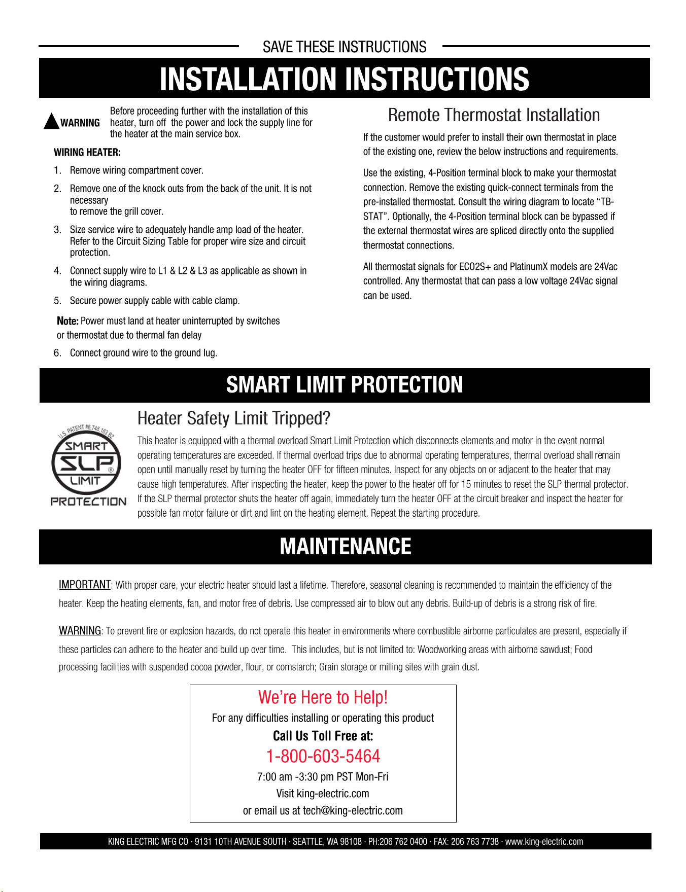
Heater Safety Limit Tripped?
This heater is equipped with a thermal overload Smart Limit Protection which disconnects elements and motor in the event normal
operating temperatures are exceeded. If thermal overload trips due to abnormal operating temperatures, thermal overload shall remain
open until manually reset by turning the heater OFF for fifteen minutes. Inspect for any objects on or adjacent to the heater that may
cause high temperatures. After inspecting the heater, keep the power to the heater off for 15 minutes to reset the SLP thermal protector.
If the SLP thermal protector shuts the heater off again, immediately turn the heater OFF at the circuit breaker and inspect the heater for
possible fan motor failure or dirt and lint on the heating element. Repeat the starting procedure.
IMPORTANT: With proper care, your electric heater should last a lifetime. Therefore, seasonal cleaning is recommended to maintain the efficiency of the
heater. Keep the heating elements, fan, and motor free of debris. Use compressed air to blow out any debris. Build-up of debris is a strong risk of fire.
WARNING: To prevent fire or explosion hazards, do not operate this heater in environments where combustible airborne particulates are present, especially if
these particles can adhere to the heater and build up over time. This includes, but is not limited to: Woodworking areas with airborne sawdust; Food
processing facilities with suspended cocoa powder, flour, or cornstarch; Grain storage or milling sites with grain dust.
We’re Here to Help!
For any difficulties installing or operating this product
Call Us Toll Free at:
1-800-603-5464
7:00 am -3:30 pm PST Mon-Fri
Visit king-electric.com
or email us at tech@king-electric.com
INSTALLATION INSTRUCTIONS
SMART LIMIT PROTECTION
MAINTENANCE
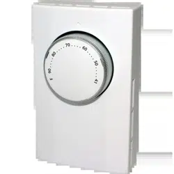
Remote Thermostat Installation
If the customer would prefer to install their own thermostat in place
of the existing one, review the below instructions and requirements.
Use the existing, 4-Position terminal block to make your thermostat
connection. Remove the existing quick-connect terminals from the
pre-installed thermostat. Consult the wiring diagram to locate “TB-
STAT”. Optionally, the 4-Position terminal block can be bypassed if
the external thermostat wires are spliced directly onto the supplied
thermostat connections.
All thermostat signals for ECO2S+ and PlatinumX models are 24Vac
controlled. Any thermostat that can pass a low voltage 24Vac signal
can be used.
2 11
SAVE THESE INSTRUCTIONS
SAFETY INFORMATION
KING ELECTRIC MFG CO · 9131 10TH AVENUE SOUTH · SEATTLE, WA 98108 · PH:206 762 0400 · FAX: 206 763 7738 · www.king-electric.com
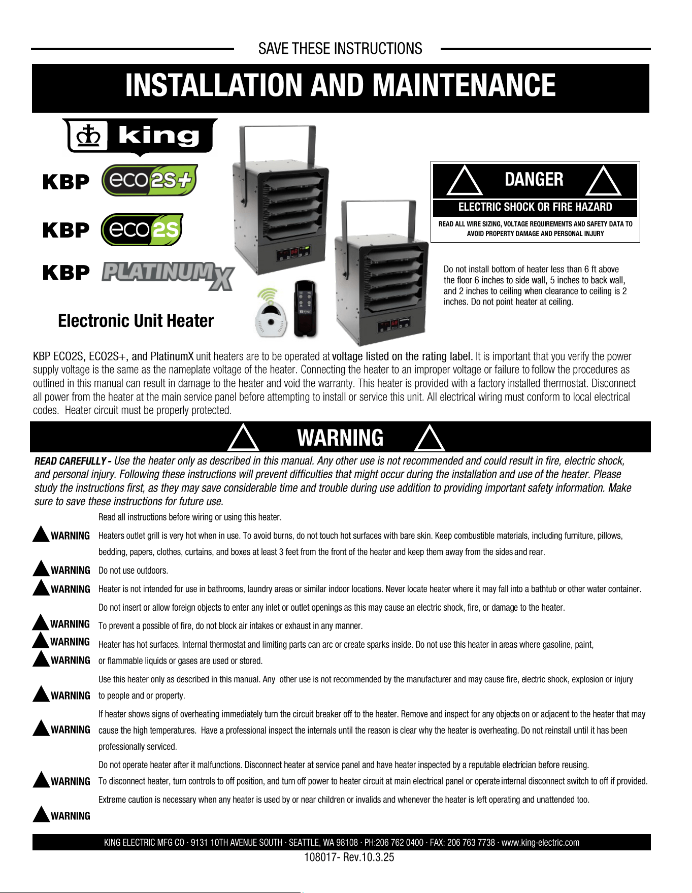
Warning: Prior to operating, make sure the circuit breaker is
of the configuration and capacity appropriate for the heater.
• Minimum installed distance from the heater to the adjoining wall or
ceiling surfaces - 5 inches to back wall.
• When clearance to ceiling is 2 inches, Do Not Point Heater At Ceiling.
• Use extreme caution when used near children or people with disabilities.
• Do not use outdoors.
• Not intended for use in bathrooms, laundry areas or other similar wet
locations. Never locate heater where it may have contact with water.
• Do not use heater in wet or moist locations.
• Don’t place heater against cardboard or low-density fiberboard surfaces.
• Avoid using an extension cord because the extension cord may overheat
and cause a risk of fire.
• Use only the electrical power (voltage and frequency) specified on the
model plate of the heater.
• Keep all combustible materials away from this heater.
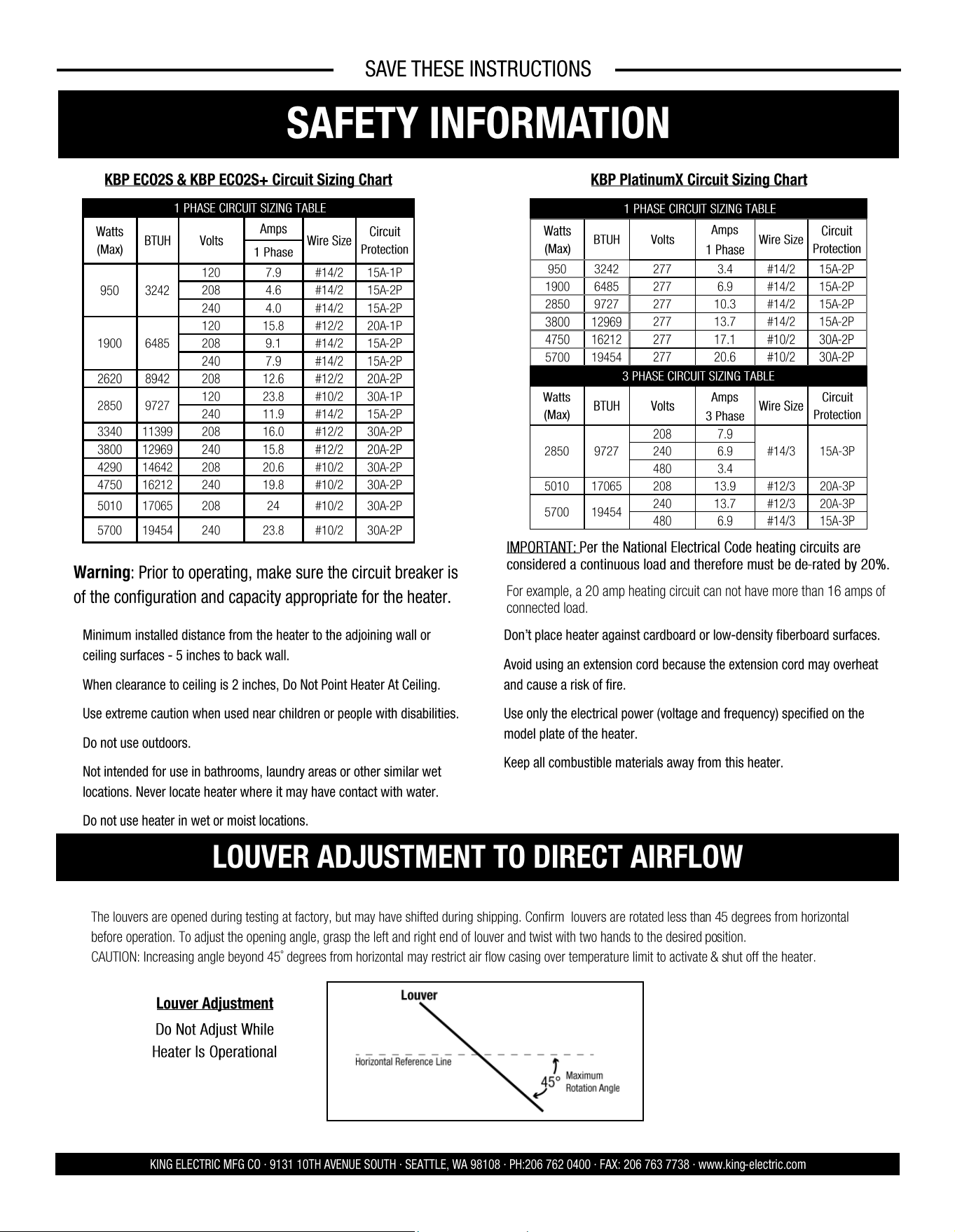
The louvers are opened during testing at factory, but may have shifted during shipping. Confirm louvers are rotated less than 45 degrees from horizontal
before operation. To adjust the opening angle, grasp the left and right end of louver and twist with two hands to the desired position.
CAUTION: Increasing angle beyond 45˚ degrees from horizontal may restrict air flow casing over temperature limit to activate & shut off the heater.
Louver Adjustment
LOUVER ADJUSTMENT TO DIRECT AIRFLOW
1 PHASE CIRCUIT SIZING TABLE
Watts
(Max)
BTUH Volts
Amps
Wire Size
Circuit
Protection
1 Phase
950 3242
120 7.9 #14/2 15A-1P
208 4.6 #14/2 15A-2P
240 4.0 #14/2 15A-2P
1900
120 15.8 #12/2 20A-1P
6485
208 9.1 #14/2 15A-2P
240 7.9 #14/2 15A-2P
2620 8942 208 12.6 #12/2 20A-2P
2850 9727
120 23.8 #10/2 30A-1P
240 11.9 #14/2 15A-2P
3340 11399 208 16.0 #12/2 30A-2P
3800 12969 240 15.8 #12/2 20A-2P
4290 14642 208 20.6 #10/2 30A-2P
4750 16212 240 19.8 #10/2 30A-2P
5010 17065 208 24 #10/2 30A-2P
5700 19454 240 23.8 #10/2 30A-2P
KBP ECO2S & KBP ECO2S+ Circuit Sizing Chart
Do Not Adjust While
Heater Is Operational
IMPORTANT: Per the National Electrical Code heating circuits are
considered a continuous load and therefore must be de-rated by 20%.
For example, a 20 amp heating circuit can not have more than 16 amps of
connected load.
1 PHASE CIRCUIT SIZING TABLE
Watts
(Max)
BTUH
Volts
Amps
Wire Size
Circuit
Protection
1 Phase
950 3242
277 3.4 #14/2 15A-2P
1900 6485 277 6.9 #14/2 15A-2P
2850 9727 277 10.3 #14/2 15A-2P
3800 12969
277 13.7 #14/2 15A-2P
4750 16212 277 17.1 #10/2 30A-2P
5700 19454
277 20.6 #10/2 30A-2P
3 PHASE CIRCUIT SIZING TABLE
Watts
(Max)
BTUH Volts
Amps
Wire Size
Circuit
Protection
3 Phase
2850 9727
208 7.9
#14/3 15A-3P 240 6.9
480 3.4
5010 17065 208 13.9 #12/3 20A-3P
5700
240 13.7 #12/3 20A-3P
19454
480 6.9 #14/3 15A-3P
KBP PlatinumX Circuit Sizing Chart
SAVE THESE INSTRUCTIONS
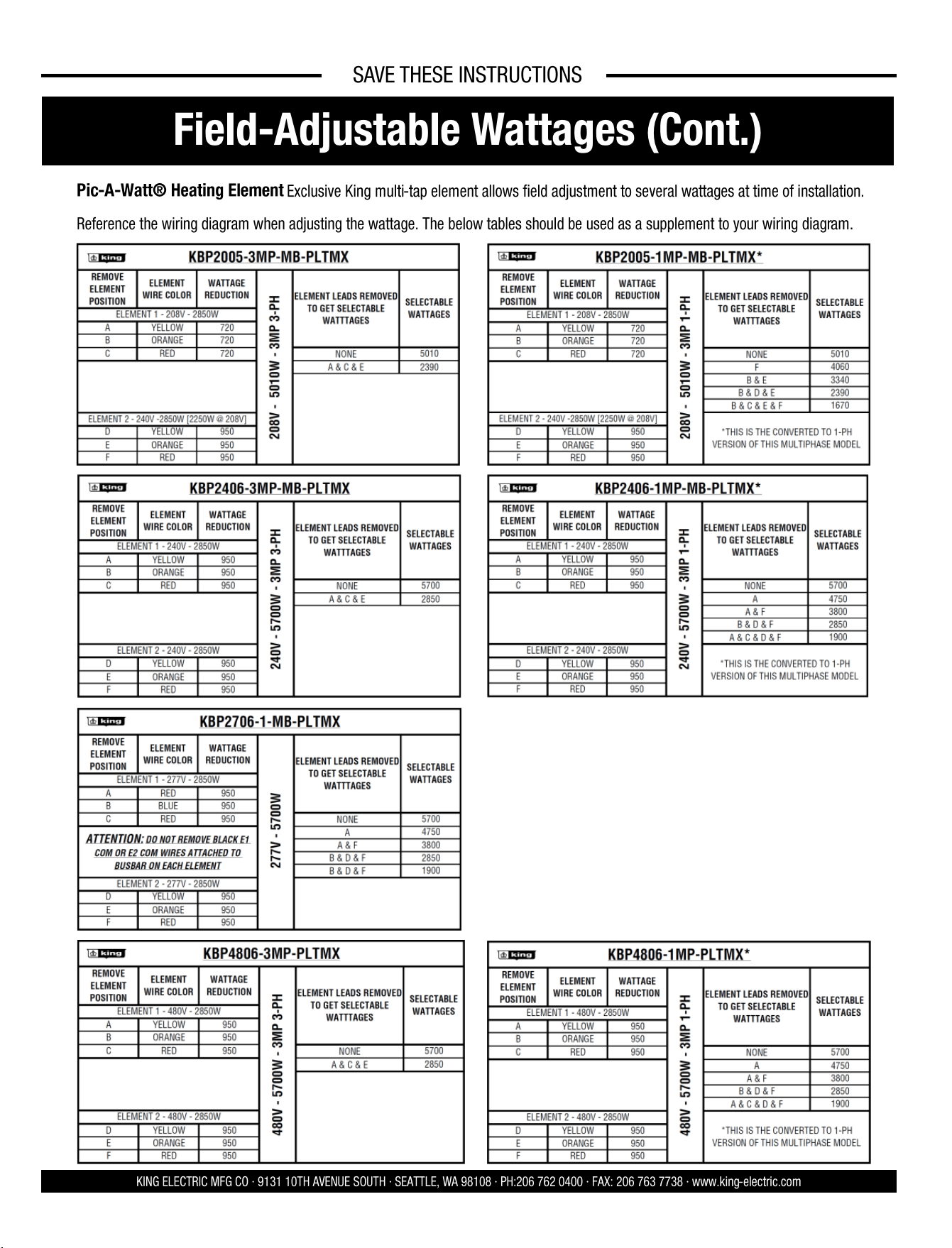
Field-Adjustable Wattages (Cont.)
KING ELECTRIC MFG CO · 9131 10TH AVENUE SOUTH · SEATTLE, WA 98108 · PH:206 762 0400 · FAX: 206 763 7738 · www.king-electric.com
Pic-A-Watt® Heating Element Exclusive King multi-tap element allows field adjustment to several wattages at time of installation.
Reference the wiring diagram when adjusting the wattage. The below tables should be used as a supplement to your wiring diagram.
10 3
SAVE THESE INSTRUCTIONS
ASSEMBLY INSTRUCTIONS
KING ELECTRIC MFG CO · 9131 10TH AVENUE SOUTH · SEATTLE, WA 98108 · PH:206 762 0400 · FAX: 206 763 7738 · www.king-electric.com
TOOLS NEEDED:
• Screwdriver (Phillips, Square, & Slotted)
• Wire Cutters
• Pliers
• Adjustable Wrench
• Electric Drill
Remove heater & all packaging materials from the box.
HARDWARE NEEDED:
• Adequate gauge & length of wire for your application
• Proper size fuses or breakers to handle amperage
• Proper wire connectors for your application
• Fasteners appropriate size to mount heater
Tip: Be sure to remove the hardware package from the Styrofoam
packaging.
MOUNTING HEIGHT:
When the air flow of the heater is directed vertically or horizontally, the minimum
mounting height is 6 feet in the USA and 8 feet in Canada. Mounting heights depend
upon building utilization and heater KW capacity.
LOCATION OF HEATER:
The heater should be installed 6 feet above floor and according to minimum clearance
chart. The direction of airflow should not be restricted by machinery, beams, etc., and
the air flow should run with walls, rather than blowing directly at them. When more
than one heater is used in an area, the heaters should be arranged so that the air
discharge of each heater supports
the air flow of the others to
provide best circulation of warm
air.
MOUNTING HEATER:
Wall stud and ceiling joists are
typically wider than our mounting
bracket which is 11 inches wide. The heater weighs 14 lbs. and should be mounted
onto at least one stud to be properly supported.
Your fasteners penetrating a stud is critical to supporting the weight. A gypsum wall
board fastener is not strong enough. If your ideal location has no solid backing, you
can fasten with large screw fasteners a 2” x 6” board to ceiling joists or wall studs.
Attach with appropriate lag bolts with proper depth for the 14 lbs. Install wing nut
fasteners into the outside of the bracket and star washer between the heater and
bracket. Be certain bracket bolts are tightened firmly to secure the heater to swivel
bracket.
*For additional mounting flexibility, an optional mounting bracket is available for sale
separately.
INSTALLATION INSTRUCTIONS
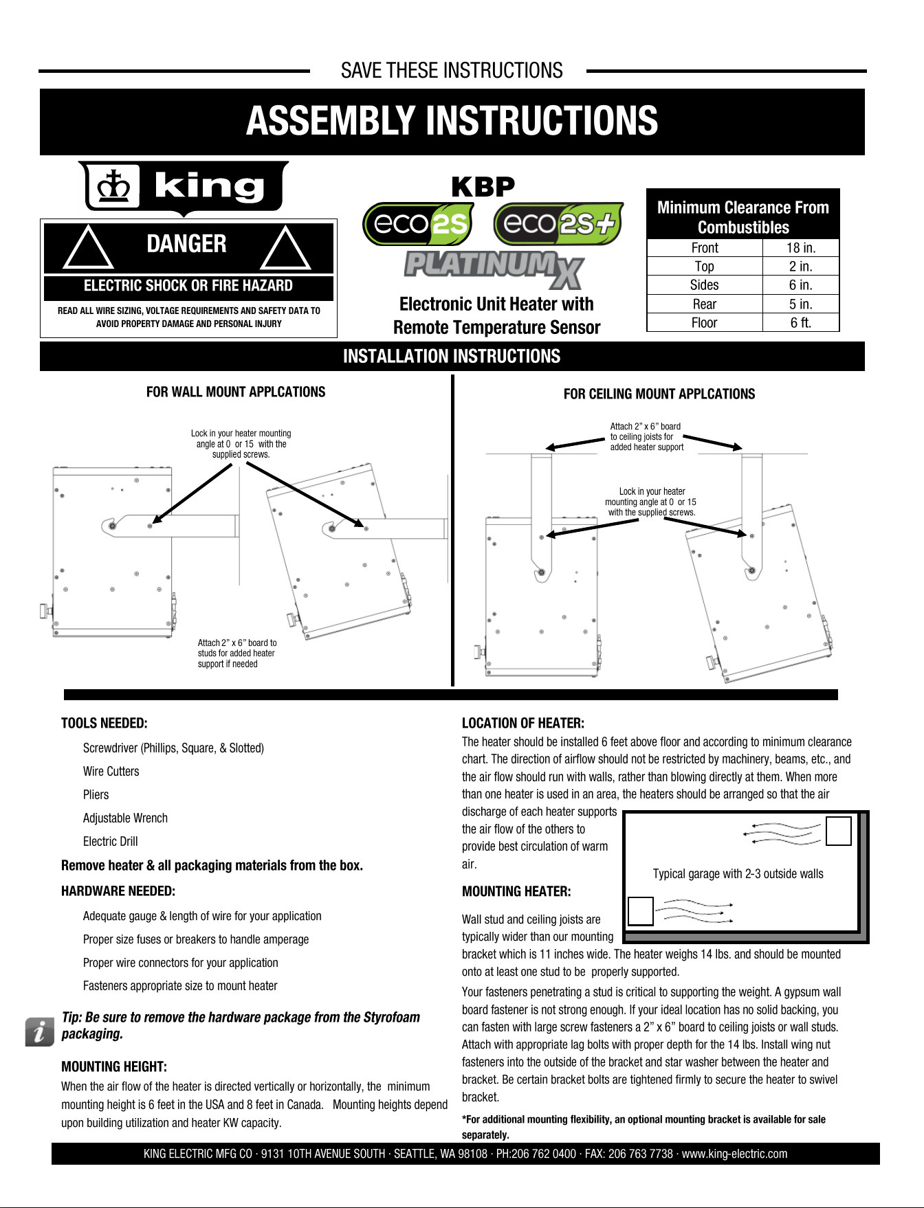
FOR WALL MOUNT APPLCATIONS
FOR CEILING MOUNT APPLCATIONS
DANGER
!
!
ELECTRIC SHOCK OR FIRE HAZARD
READ ALL WIRE SIZING, VOLTAGE REQUIREMENTS AND SAFETY DATA TO
AVOID PROPERTY DAMAGE AND PERSONAL INJURY
Typical garage with 2-3 outside walls
Attach 2” x 6” board
to ceiling joists for
added heater support
Minimum Clearance From
Combustibles
Front 18 in.
Top 2 in.
Sides 6 in.
Rear 5 in.
Floor 6 ft.
KBP
Electronic Unit Heater with
Remote Temperature Sensor
Attach 2” x 6” board to
studs for added heater
support if needed
Lock in your heater mounting
angle at 0° or 15° with the
supplied screws.
Lock in your heater
mounting angle at 0° or 15°
with the supplied screws.
SAVE THESE INSTRUCTIONS
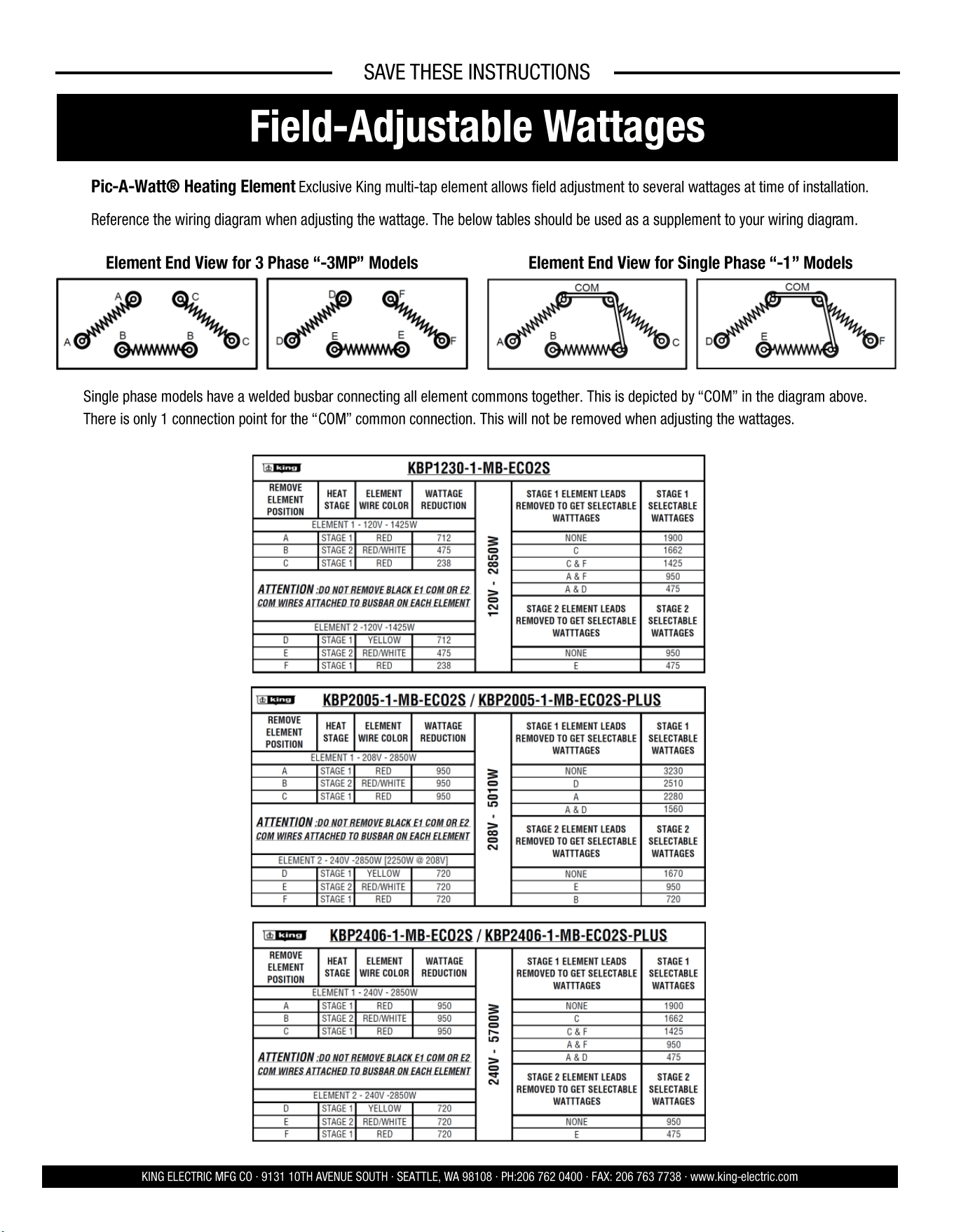
Field-Adjustable Wattages
KING ELECTRIC MFG CO · 9131 10TH AVENUE SOUTH · SEATTLE, WA 98108 · PH:206 762 0400 · FAX: 206 763 7738 · www.king-electric.com
Pic-A-Watt® Heating Element Exclusive King multi-tap element allows field adjustment to several wattages at time of installation.
Reference the wiring diagram when adjusting the wattage. The below tables should be used as a supplement to your wiring diagram.
Single phase models have a welded busbar connecting all element commons together. This is depicted by “COM” in the diagram above.
There is only 1 connection point for the “COM” common connection. This will not be removed when adjusting the wattages.
Element End View for 3 Phase “-3MP” Models Element End View for Single Phase “-1” Models
4 9
SAVE THESE INSTRUCTIONS
KING ELECTRIC MFG CO · 9131 10TH AVENUE SOUTH · SEATTLE, WA 98108 · PH:206 762 0400 · FAX: 206 763 7738 · www.king-electric.com
SETUP OF REMOTE TEMPERATURE SENSOR FOR ECO2S+
A wireless temperature sensor is provided to monitor the ambient temperature
from any remote location. It needs to be paired with the heater and will transmit
real-time temperature to the heater for highly accurate room temperature control.
Sensor Placement
Important: Avoid areas that can have temperature extremes, making the sensor think
the room is cooler or warmer than it actually is. Don't install the sensor near doors
that could let in drafts or on exterior walls or near windows in direct sunlight.
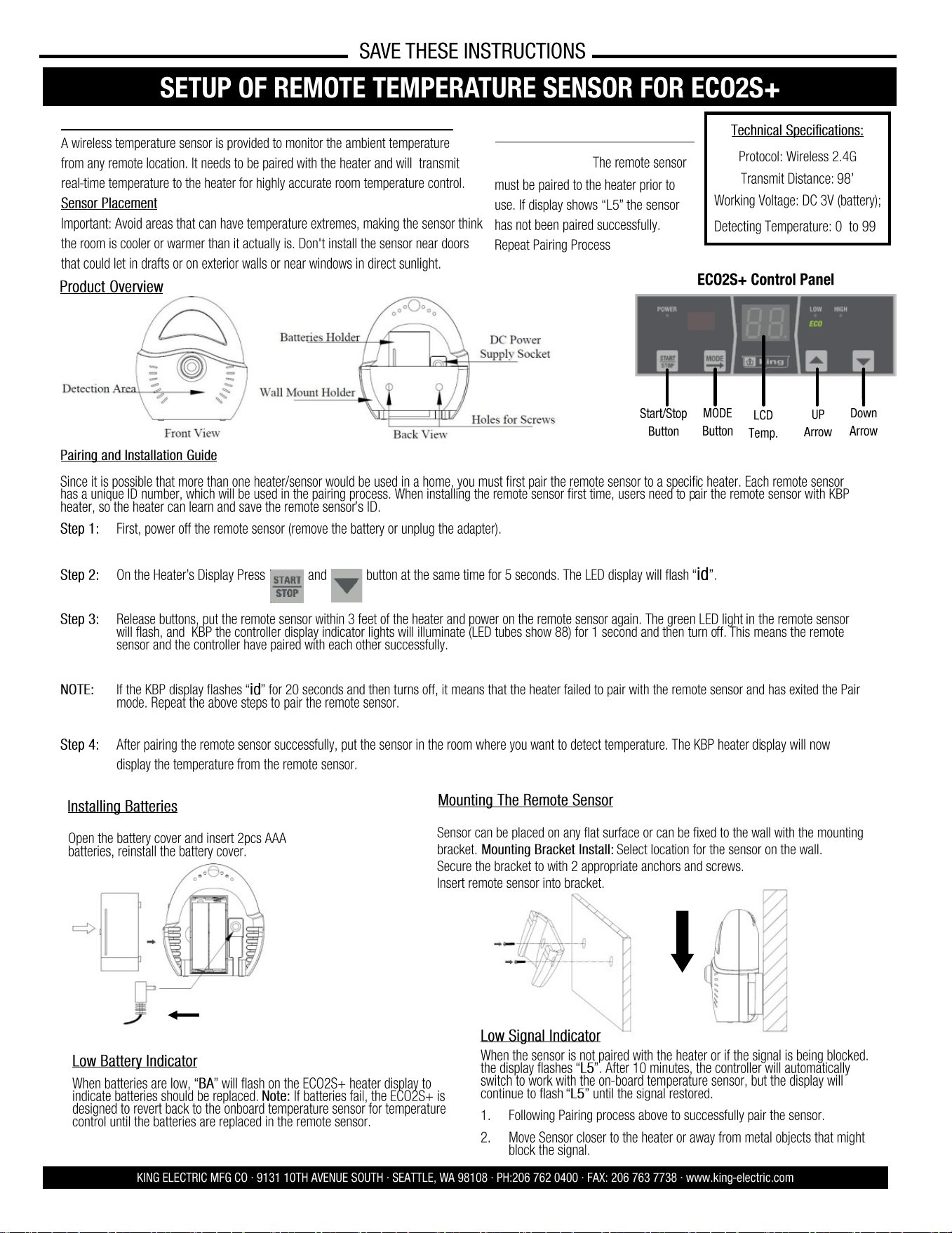
Product Overview
Installing Batteries
Sensor can be placed on any flat surface or can be fixed to the wall with the mounting
bracket. Mounting Bracket Install: Select location for the sensor on the wall.
Secure the bracket to with 2 appropriate anchors and screws.
Insert remote sensor into bracket.
Mounting The Remote Sensor
Open the battery cover and insert 2pcs AAA
batteries, reinstall the battery cover.
Technical Specifications:
Protocol: Wireless 2.4G
Transmit Distance: 98’
Working Voltage: DC 3V (battery);
Detecting Temperature: 0° to 99°
Low Battery Indicator
When batteries are low, “BA” will flash on the ECO2S+ heater display to
indicate batteries should be replaced. Note: If batteries fail, the ECO2S+ is
designed to revert back to the onboard temperature sensor for temperature
control until the batteries are replaced in the remote sensor.
LCD
Temp.
ECO2S+ Control Panel
Start/Stop
Button
MODE
Button
UP
Arrow
Down
Arrow
Oponal Accessory #EC02S-5V-PWRSPLY
Pairing and Installation Guide
Since it is possible that more than one heater/sensor would be used in a home, you must first pair the remote sensor to a specific heater. Each remote sensor
has a unique ID number, which will be used in the pairing process. When installing the remote sensor first time, users need to pair the remote sensor with KBP
heater, so the heater can learn and save the remote sensor’s ID.
Step 1: First, power off the remote sensor (remove the battery or unplug the adapter).
Step 2: On the Heater’s Display Press and button at the same time for 5 seconds. The LED display will flash “id”.
Step 3: Release buttons, put the remote sensor within 3 feet of the heater and power on the remote sensor again. The green LED light in the remote sensor
will flash, and KBP the controller display indicator lights will illuminate (LED tubes show 88) for 1 second and then turn off. This means the remote
sensor and the controller have paired with each other successfully.
NOTE: If the KBP display flashes “id” for 20 seconds and then turns off, it means that the heater failed to pair with the remote sensor and has exited the Pair
mode. Repeat the above steps to pair the remote sensor.
Step 4: After pairing the remote sensor successfully, put the sensor in the room where you want to detect temperature. The KBP heater display will now
display the temperature from the remote sensor.
Low Signal Indicator
When the sensor is not paired with the heater or if the signal is being blocked.
the display flashes “L5”. After 10 minutes, the controller will automatically
switch to work with the on-board temperature sensor, but the display will
continue to flash “L5” until the signal restored.
1. Following Pairing process above to successfully pair the sensor.
2. Move Sensor closer to the heater or away from metal objects that might
block the signal.
ECO2S+ REMOTE SENSOR:
IMPORTANT: The remote sensor
must be paired to the heater prior to
use. If display shows “L5” the sensor
has not been paired successfully.
Repeat Pairing Process
Remote Sensor Only Included with ECO2S+ Models
OPEATING INSTRUC- TIONS
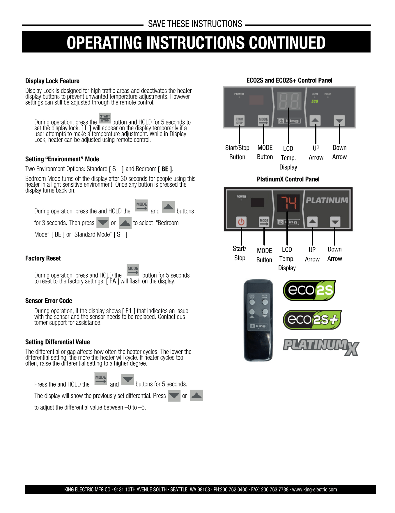
Display Lock Feature
Display Lock is designed for high traffic areas and deactivates the heater
display buttons to prevent unwanted temperature adjustments. However
settings can still be adjusted through the remote control.
• During operation, press the
button and HOLD for 5 seconds to
set the display lock. [ L ] will appear on the display temporarily if a
user attempts to make a temperature adjustment. While in Display
Lock, heater can be adjusted using remote control.
Setting “Environment” Mode
Two Environment Options: Standard [ SΓ ] and Bedroom [ BE ].
Bedroom Mode turns off the display after 30 seconds for people using this
heater in a light sensitive environment. Once any button is pressed the
display turns back on.
• During operation, press the and HOLD the and buttons
for 3 seconds. Then press or to select “Bedroom
Mode” [ BE ] or “Standard Mode” [ SΓ ]
Factory Reset
• During operation, press and HOLD the button for 5 seconds
to reset to the factory settings. [ FA ] will flash on the display.
Sensor Error Code
• During operation, if the display shows [ E1 ] that indicates an issue
with the sensor and the sensor needs to be replaced. Contact cus-
tomer support for assistance.
Setting Differential Value
The differential or gap affects how often the heater cycles. The lower the
differential setting, the more the heater will cycle. If heater cycles too
often, raise the differential setting to a higher degree.
• Press the and HOLD the and
buttons for 5 seconds.
The display will show the previously set differential. Press or
to adjust the differential value between –0 to –5.
ECO2S OPERATING INSTRUCTIONS
KING ELECTRIC MFG CO · 9131 10TH AVENUE SOUTH · SEATTLE, WA 98108 · PH:206 762 0400 · FAX: 206 763 7738 · www.king-electric.com
SAVE THESE INSTRUCTIONS
OPERATING INSTRUCTIONS CONTINUED
LCD
Temp.
Display
ECO2S and ECO2S+ Control Panel
Start/Stop
Button
MODE
Button
UP
Arrow
Down
Arrow
LCD
Temp.
Display
PlatinumX Control Panel
Start/
Stop
MODE
Button
UP
Arrow
Down
Arrow
8 5
KING ELECTRIC MFG CO · 9131 10TH AVENUE SOUTH · SEATTLE, WA 98108 · PH:206 762 0400 · FAX: 206 763 7738 · www.king-electric.com
CONNECTION OF OPTIONAL 24V REMOTE THERMOSTAT
SAVE THESE INSTRUCTIONS
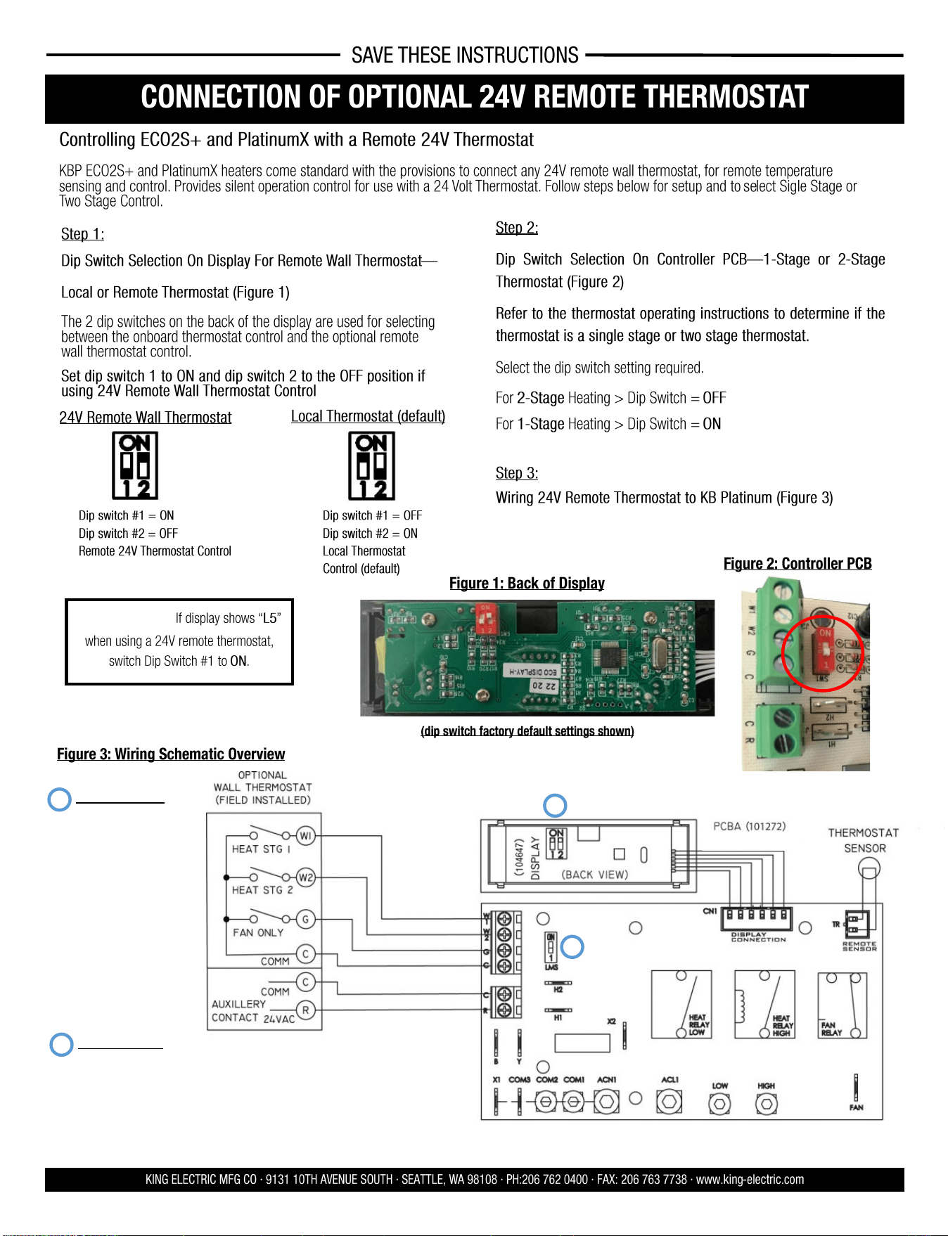
Step 1:
Dip Switch Selection On Display For Remote Wall Thermostat—
Local or Remote Thermostat (Figure 1)
The 2 dip switches on the back of the display are used for selecting
between the onboard thermostat control and the optional remote
wall thermostat control.
Set dip switch 1 to ON and dip switch 2 to the OFF position if
using 24V Remote Wall Thermostat Control
Figure 1: Back of Display
Figure 2: Controller PCB
Figure 3: Wiring Schematic Overview
Controlling ECO2S+ and PlatinumX with a Remote 24V Thermostat
KBP ECO2S+ and PlatinumX heaters come standard with the provisions to connect any 24V remote wall thermostat, for remote temperature
sensing and control. Provides silent operation control for use with a 24 Volt Thermostat. Follow steps below for setup and to select Sigle Stage or
Two Stage Control.
Step 2:
Dip Switch Selection On Controller PCB—1-Stage or 2 -Stage
Thermostat (Figure 2)
Refer to the thermostat operating instructions to determine if the
thermostat is a single stage or two stage thermostat.
Select the dip switch setting required.
For 2-Stage Heating > Dip Switch = OFF
For 1-Stage Heating > Dip Switch = ON
Step 3:
Wiring 24V Remote Thermostat to KB Platinum (Figure 3)
Dip switch #1 = ON
Dip switch #2 = OFF
Remote 24V Thermostat Control
Dip switch #1 = OFF
Dip switch #2 = ON
Local Thermostat
Control (default)
24V Remote Wall Thermostat
Local Thermostat (default)
(dip switch factory default settings shown)
1
2
DISPLAY (104647)
DIP SWITCH 1
OFF = EXTERNAL SENSOR
CONTROL (102806) (DEFAULT
SETTING)
ON = LOCAL SENSOR CON-
TROL
DIP SWITCH 2
OFF= REMOTE STAT
(CUSTOMER PROVIDED)
ON = LOCAL STAT (CONTROL
SETTING BY DISPLAY)
(DEFAULT)
CONTROL BOARD (101272)
DIP SWITCH LMS
ON = SINGLE STAGE REMOTE
STAT (DEFAULT)
OFF = TWO STAGE REMOTE
STAT
2
1
IMPORTANT: If display shows “L5”
when using a 24V remote thermostat,
switch Dip Switch #1 to ON.
OPEATING INSTRUC- TIONS
ECO2S OPERATING INSTRUCTIONS
KING ELECTRIC MFG CO · 9131 10TH AVENUE SOUTH · SEATTLE, WA 98108 · PH:206 762 0400 · FAX: 206 763 7738 · www.king-electric.com
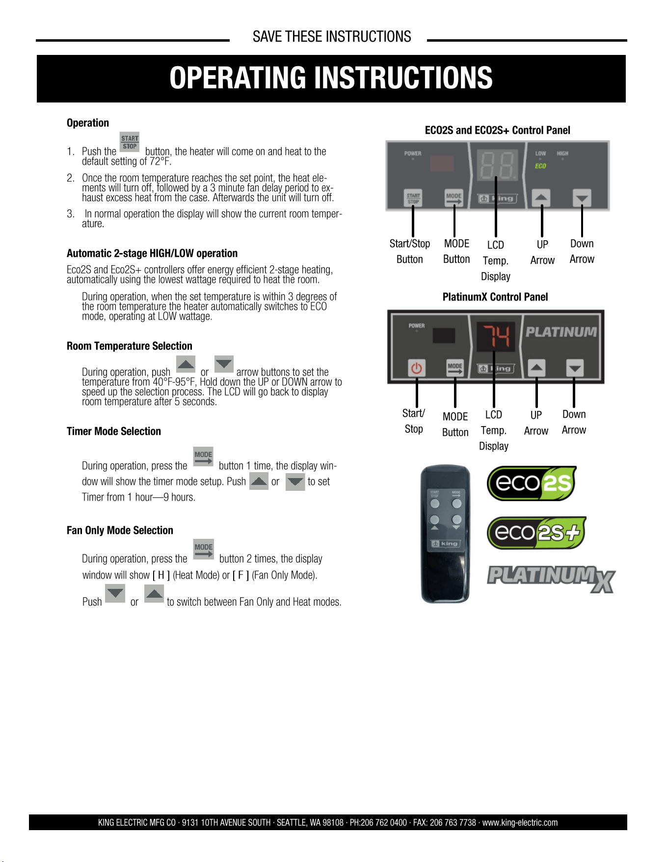
Operation
1. Push the button, the heater will come on and heat to the
default setting of 72°F.
2. Once the room temperature reaches the set point, the heat ele-
ments will turn off, followed by a 3 minute fan delay period to ex-
haust excess heat from the case. Afterwards the unit will turn off.
3. In normal operation the display will show the current room temper-
ature.
Automatic 2-stage HIGH/LOW operation
Eco2S and Eco2S+ controllers offer energy efficient 2-stage heating,
automatically using the lowest wattage required to heat the room.
• During operation, when the set temperature is within 3 degrees of
the room temperature the heater automatically switches to ECO
mode, operating at LOW wattage.
Room Temperature Selection
• During operation, push or arrow buttons to set the
temperature from 40°F-95°F, Hold down the UP or DOWN arrow to
speed up the selection process. The LCD will go back to display
room temperature after 5 seconds.
Timer Mode Selection
• During operation, press the button 1 time, the display win-
dow will show the timer mode setup. Push or to set
Timer from 1 hour—9 hours.
Fan Only Mode Selection
• During operation, press the button 2 times, the display
window will show [ H ] (Heat Mode) or [ F ] (Fan Only Mode).
Push or to switch between Fan Only and Heat modes.
LCD
Temp.
Display
ECO2S and ECO2S+ Control Panel
Start/Stop
Button
MODE
Button
UP
Arrow
Down
Arrow
SAVE THESE INSTRUCTIONS
OPERATING INSTRUCTIONS
LCD
Temp.
Display
PlatinumX Control Panel
Start/
Stop
MODE
Button
UP
Arrow
Down
Arrow
6 7
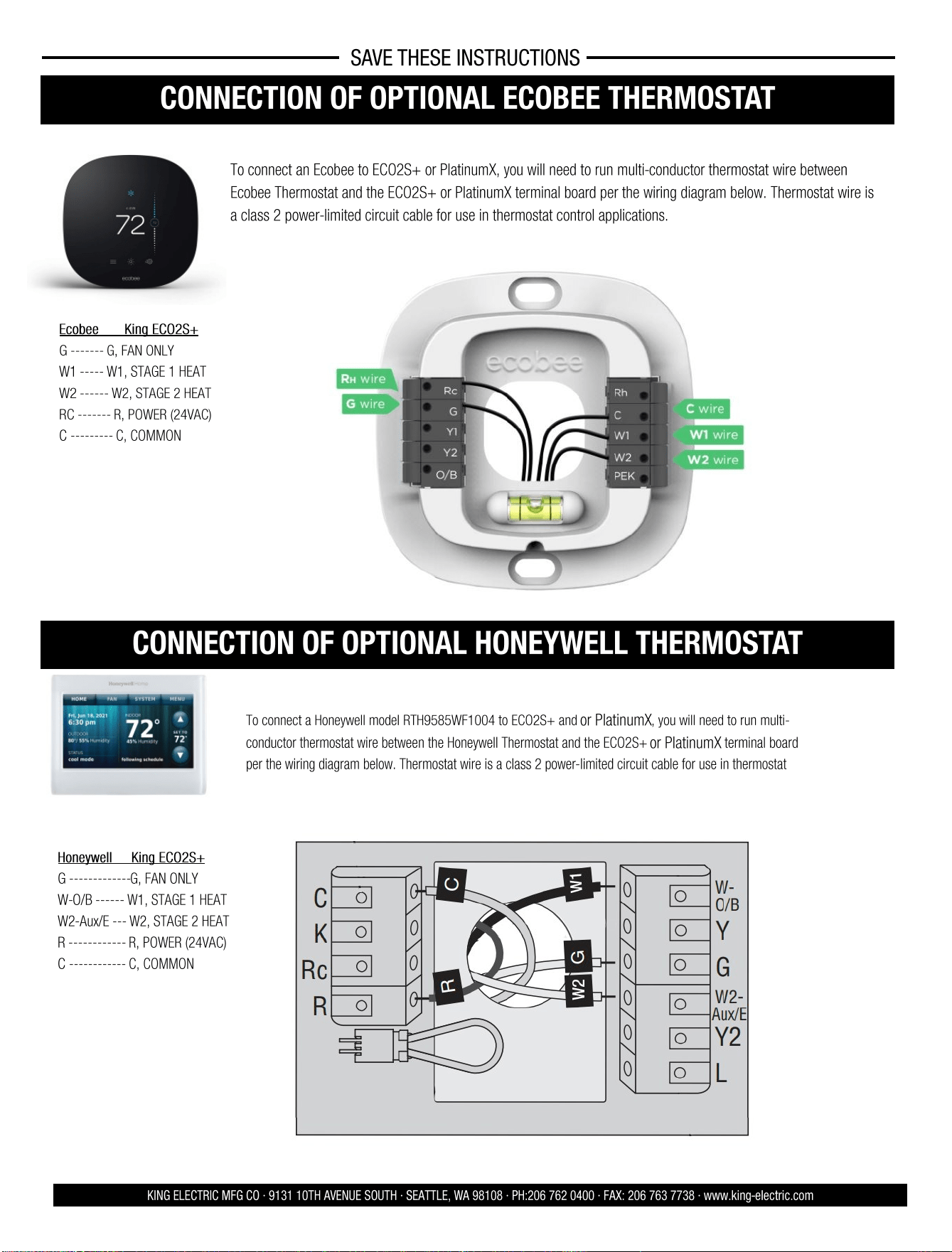
CONNECTION OF OPTIONAL ECOBEE THERMOSTAT
To connect an Ecobee to ECO2S+ or PlatinumX, you will need to run multi-conductor thermostat wire between
Ecobee Thermostat and the ECO2S+ or PlatinumX terminal board per the wiring diagram below. Thermostat wire is
a class 2 power-limited circuit cable for use in thermostat control applications.
KING ELECTRIC MFG CO · 9131 10TH AVENUE SOUTH · SEATTLE, WA 98108 · PH:206 762 0400 · FAX: 206 763 7738 · www.king-electric.com
SAVE THESE INSTRUCTIONS
Conventional 2 Stage Heating
Ecobee King ECO2S+
G ------- G, FAN ONLY
W1 ----- W1, STAGE 1 HEAT
W2 ------ W2, STAGE 2 HEAT
RC ------- R, POWER (24VAC)
C --------- C, COMMON
CONNECTION OF OPTIONAL HONEYWELL THERMOSTAT
Honeywell King ECO2S+
G ------------- G, FAN ONLY
W-O/B ------ W1, STAGE 1 HEAT
W2-Aux/E --- W2, STAGE 2 HEAT
R ------------ R, POWER (24VAC)
C ------------ C, COMMON
To connect a Honeywell model RTH9585WF1004 to ECO2S+ and or PlatinumX, you will need to run multi-
conductor thermostat wire between the Honeywell Thermostat and the ECO2S+ or PlatinumX terminal board
per the wiring diagram below. Thermostat wire is a class 2 power-limited circuit cable for use in thermostat
Conventional 2 Stage Heating
Model: RTH9585WF1004
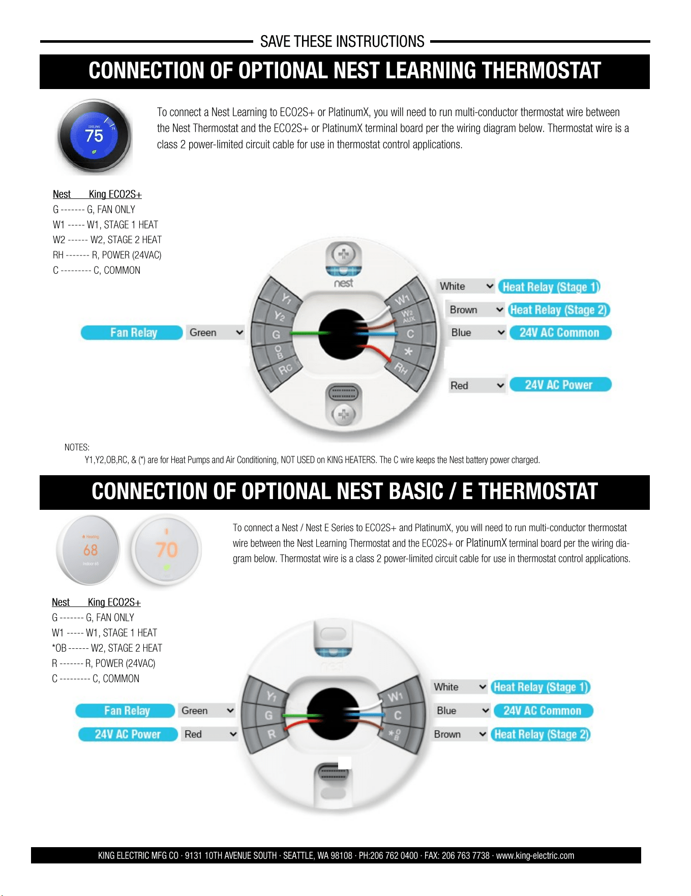
CONNECTION OF OPTIONAL NEST LEARNING THERMOSTAT
To connect a Nest Learning to ECO2S+ or PlatinumX, you will need to run multi-conductor thermostat wire between
the Nest Thermostat and the ECO2S+ or PlatinumX terminal board per the wiring diagram below. Thermostat wire is a
class 2 power-limited circuit cable for use in thermostat control applications.
KING ELECTRIC MFG CO · 9131 10TH AVENUE SOUTH · SEATTLE, WA 98108 · PH:206 762 0400 · FAX: 206 763 7738 · www.king-electric.com
Conventional 2 Stage Heating
Nest King ECO2S+
G ------- G, FAN ONLY
W1 ----- W1, STAGE 1 HEAT
W2 ------ W2, STAGE 2 HEAT
RH ------- R, POWER (24VAC)
C --------- C, COMMON
NOTES:
• Y1,Y2,OB,RC, & (*) are for Heat Pumps and Air Conditioning, NOT USED on KING HEATERS. The C wire keeps the Nest battery power charged.
CONNECTION OF OPTIONAL NEST BASIC / E THERMOSTAT
Conventional 2 Stage Heating
Nest King ECO2S+
G ------- G, FAN ONLY
W1 ----- W1, STAGE 1 HEAT
*OB ------ W2, STAGE 2 HEAT
R ------- R, POWER (24VAC)
C --------- C, COMMON
To connect a Nest / Nest E Series to ECO2S+ and PlatinumX, you will need to run multi-conductor thermostat
wire between the Nest Learning Thermostat and the ECO2S+ or PlatinumX terminal board per the wiring dia-
gram below. Thermostat wire is a class 2 power-limited circuit cable for use in thermostat control applications.
SAVE THESE INSTRUCTIONS
6 7
CONNECTION OF OPTIONAL ECOBEE THERMOSTAT
To connect an Ecobee to ECO2S+ or PlatinumX, you will need to run multi-conductor thermostat wire between
Ecobee Thermostat and the ECO2S+ or PlatinumX terminal board per the wiring diagram below. Thermostat wire is
a class 2 power-limited circuit cable for use in thermostat control applications.
KING ELECTRIC MFG CO · 9131 10TH AVENUE SOUTH · SEATTLE, WA 98108 · PH:206 762 0400 · FAX: 206 763 7738 · www.king-electric.com
SAVE THESE INSTRUCTIONS
Conventional 2 Stage Heating
Ecobee King ECO2S+
G ------- G, FAN ONLY
W1 ----- W1, STAGE 1 HEAT
W2 ------ W2, STAGE 2 HEAT
RC ------- R, POWER (24VAC)
C --------- C, COMMON
CONNECTION OF OPTIONAL HONEYWELL THERMOSTAT
Honeywell King ECO2S+
G ------------- G, FAN ONLY
W-O/B ------ W1, STAGE 1 HEAT
W2-Aux/E --- W2, STAGE 2 HEAT
R ------------ R, POWER (24VAC)
C ------------ C, COMMON
To connect a Honeywell model RTH9585WF1004 to ECO2S+ and or PlatinumX, you will need to run multi-
conductor thermostat wire between the Honeywell Thermostat and the ECO2S+ or PlatinumX terminal board
per the wiring diagram below. Thermostat wire is a class 2 power-limited circuit cable for use in thermostat
Conventional 2 Stage Heating
Model: RTH9585WF1004
CONNECTION OF OPTIONAL NEST LEARNING THERMOSTAT
To connect a Nest Learning to ECO2S+ or PlatinumX, you will need to run multi-conductor thermostat wire between
the Nest Thermostat and the ECO2S+ or PlatinumX terminal board per the wiring diagram below. Thermostat wire is a
class 2 power-limited circuit cable for use in thermostat control applications.
KING ELECTRIC MFG CO · 9131 10TH AVENUE SOUTH · SEATTLE, WA 98108 · PH:206 762 0400 · FAX: 206 763 7738 · www.king-electric.com
Conventional 2 Stage Heating
Nest King ECO2S+
G ------- G, FAN ONLY
W1 ----- W1, STAGE 1 HEAT
W2 ------ W2, STAGE 2 HEAT
RH ------- R, POWER (24VAC)
C --------- C, COMMON
NOTES:
• Y1,Y2,OB,RC, & (*) are for Heat Pumps and Air Conditioning, NOT USED on KING HEATERS. The C wire keeps the Nest battery power charged.
CONNECTION OF OPTIONAL NEST BASIC / E THERMOSTAT
Conventional 2 Stage Heating
Nest King ECO2S+
G ------- G, FAN ONLY
W1 ----- W1, STAGE 1 HEAT
*OB ------ W2, STAGE 2 HEAT
R ------- R, POWER (24VAC)
C --------- C, COMMON
To connect a Nest / Nest E Series to ECO2S+ and PlatinumX, you will need to run multi-conductor thermostat
wire between the Nest Learning Thermostat and the ECO2S+ or PlatinumX terminal board per the wiring dia-
gram below. Thermostat wire is a class 2 power-limited circuit cable for use in thermostat control applications.
SAVE THESE INSTRUCTIONS
8 5
KING ELECTRIC MFG CO · 9131 10TH AVENUE SOUTH · SEATTLE, WA 98108 · PH:206 762 0400 · FAX: 206 763 7738 · www.king-electric.com
CONNECTION OF OPTIONAL 24V REMOTE THERMOSTAT
SAVE THESE INSTRUCTIONS
Step 1:
Dip Switch Selection On Display For Remote Wall Thermostat—
Local or Remote Thermostat (Figure 1)
The 2 dip switches on the back of the display are used for selecting
between the onboard thermostat control and the optional remote
wall thermostat control.
Set dip switch 1 to ON and dip switch 2 to the OFF position if
using 24V Remote Wall Thermostat Control
Figure 1: Back of Display
Figure 2: Controller PCB
Figure 3: Wiring Schematic Overview
Controlling ECO2S+ and PlatinumX with a Remote 24V Thermostat
KBP ECO2S+ and PlatinumX heaters come standard with the provisions to connect any 24V remote wall thermostat, for remote temperature
sensing and control. Provides silent operation control for use with a 24 Volt Thermostat. Follow steps below for setup and to select Sigle Stage or
Two Stage Control.
Step 2:
Dip Switch Selection On Controller PCB—1-Stage or 2 -Stage
Thermostat (Figure 2)
Refer to the thermostat operating instructions to determine if the
thermostat is a single stage or two stage thermostat.
Select the dip switch setting required.
For 2-Stage Heating > Dip Switch = OFF
For 1-Stage Heating > Dip Switch = ON
Step 3:
Wiring 24V Remote Thermostat to KB Platinum (Figure 3)
Dip switch #1 = ON
Dip switch #2 = OFF
Remote 24V Thermostat Control
Dip switch #1 = OFF
Dip switch #2 = ON
Local Thermostat
Control (default)
24V Remote Wall Thermostat
Local Thermostat (default)
(dip switch factory default settings shown)
1
2
DISPLAY (104647)
DIP SWITCH 1
OFF = EXTERNAL SENSOR
CONTROL (102806) (DEFAULT
SETTING)
ON = LOCAL SENSOR CON-
TROL
DIP SWITCH 2
OFF= REMOTE STAT
(CUSTOMER PROVIDED)
ON = LOCAL STAT (CONTROL
SETTING BY DISPLAY)
(DEFAULT)
CONTROL BOARD (101272)
DIP SWITCH LMS
ON = SINGLE STAGE REMOTE
STAT (DEFAULT)
OFF = TWO STAGE REMOTE
STAT
2
1
IMPORTANT: If display shows “L5”
when using a 24V remote thermostat,
switch Dip Switch #1 to ON.
OPEATING INSTRUC- TIONS
ECO2S OPERATING INSTRUCTIONS
KING ELECTRIC MFG CO · 9131 10TH AVENUE SOUTH · SEATTLE, WA 98108 · PH:206 762 0400 · FAX: 206 763 7738 · www.king-electric.com
Operation
1. Push the button, the heater will come on and heat to the
default setting of 72°F.
2. Once the room temperature reaches the set point, the heat ele-
ments will turn off, followed by a 3 minute fan delay period to ex-
haust excess heat from the case. Afterwards the unit will turn off.
3. In normal operation the display will show the current room temper-
ature.
Automatic 2-stage HIGH/LOW operation
Eco2S and Eco2S+ controllers offer energy efficient 2-stage heating,
automatically using the lowest wattage required to heat the room.
• During operation, when the set temperature is within 3 degrees of
the room temperature the heater automatically switches to ECO
mode, operating at LOW wattage.
Room Temperature Selection
• During operation, push or arrow buttons to set the
temperature from 40°F-95°F, Hold down the UP or DOWN arrow to
speed up the selection process. The LCD will go back to display
room temperature after 5 seconds.
Timer Mode Selection
• During operation, press the button 1 time, the display win-
dow will show the timer mode setup. Push or to set
Timer from 1 hour—9 hours.
Fan Only Mode Selection
• During operation, press the button 2 times, the display
window will show [ H ] (Heat Mode) or [ F ] (Fan Only Mode).
Push or to switch between Fan Only and Heat modes.
LCD
Temp.
Display
ECO2S and ECO2S+ Control Panel
Start/Stop
Button
MODE
Button
UP
Arrow
Down
Arrow
SAVE THESE INSTRUCTIONS
OPERATING INSTRUCTIONS
LCD
Temp.
Display
PlatinumX Control Panel
Start/
Stop
MODE
Button
UP
Arrow
Down
Arrow
4 9
SAVE THESE INSTRUCTIONS
KING ELECTRIC MFG CO · 9131 10TH AVENUE SOUTH · SEATTLE, WA 98108 · PH:206 762 0400 · FAX: 206 763 7738 · www.king-electric.com
SETUP OF REMOTE TEMPERATURE SENSOR FOR ECO2S+
A wireless temperature sensor is provided to monitor the ambient temperature
from any remote location. It needs to be paired with the heater and will transmit
real-time temperature to the heater for highly accurate room temperature control.
Sensor Placement
Important: Avoid areas that can have temperature extremes, making the sensor think
the room is cooler or warmer than it actually is. Don't install the sensor near doors
that could let in drafts or on exterior walls or near windows in direct sunlight.
Product Overview
Installing Batteries
Sensor can be placed on any flat surface or can be fixed to the wall with the mounting
bracket. Mounting Bracket Install: Select location for the sensor on the wall.
Secure the bracket to with 2 appropriate anchors and screws.
Insert remote sensor into bracket.
Mounting The Remote Sensor
Open the battery cover and insert 2pcs AAA
batteries, reinstall the battery cover.
Technical Specifications:
Protocol: Wireless 2.4G
Transmit Distance: 98’
Working Voltage: DC 3V (battery);
Detecting Temperature: 0° to 99°
Low Battery Indicator
When batteries are low, “BA” will flash on the ECO2S+ heater display to
indicate batteries should be replaced. Note: If batteries fail, the ECO2S+ is
designed to revert back to the onboard temperature sensor for temperature
control until the batteries are replaced in the remote sensor.
LCD
Temp.
ECO2S+ Control Panel
Start/Stop
Button
MODE
Button
UP
Arrow
Down
Arrow
Oponal Accessory #EC02S-5V-PWRSPLY
Pairing and Installation Guide
Since it is possible that more than one heater/sensor would be used in a home, you must first pair the remote sensor to a specific heater. Each remote sensor
has a unique ID number, which will be used in the pairing process. When installing the remote sensor first time, users need to pair the remote sensor with KBP
heater, so the heater can learn and save the remote sensor’s ID.
Step 1: First, power off the remote sensor (remove the battery or unplug the adapter).
Step 2: On the Heater’s Display Press and button at the same time for 5 seconds. The LED display will flash “id”.
Step 3: Release buttons, put the remote sensor within 3 feet of the heater and power on the remote sensor again. The green LED light in the remote sensor
will flash, and KBP the controller display indicator lights will illuminate (LED tubes show 88) for 1 second and then turn off. This means the remote
sensor and the controller have paired with each other successfully.
NOTE: If the KBP display flashes “id” for 20 seconds and then turns off, it means that the heater failed to pair with the remote sensor and has exited the Pair
mode. Repeat the above steps to pair the remote sensor.
Step 4: After pairing the remote sensor successfully, put the sensor in the room where you want to detect temperature. The KBP heater display will now
display the temperature from the remote sensor.
Low Signal Indicator
When the sensor is not paired with the heater or if the signal is being blocked.
the display flashes “L5”. After 10 minutes, the controller will automatically
switch to work with the on-board temperature sensor, but the display will
continue to flash “L5” until the signal restored.
1. Following Pairing process above to successfully pair the sensor.
2. Move Sensor closer to the heater or away from metal objects that might
block the signal.
ECO2S+ REMOTE SENSOR:
IMPORTANT: The remote sensor
must be paired to the heater prior to
use. If display shows “L5” the sensor
has not been paired successfully.
Repeat Pairing Process
Remote Sensor Only Included with ECO2S+ Models
OPEATING INSTRUC- TIONS
Display Lock Feature
Display Lock is designed for high traffic areas and deactivates the heater
display buttons to prevent unwanted temperature adjustments. However
settings can still be adjusted through the remote control.
• During operation, press the
button and HOLD for 5 seconds to
set the display lock. [ L ] will appear on the display temporarily if a
user attempts to make a temperature adjustment. While in Display
Lock, heater can be adjusted using remote control.
Setting “Environment” Mode
Two Environment Options: Standard [ SΓ ] and Bedroom [ BE ].
Bedroom Mode turns off the display after 30 seconds for people using this
heater in a light sensitive environment. Once any button is pressed the
display turns back on.
• During operation, press the and HOLD the and buttons
for 3 seconds. Then press or to select “Bedroom
Mode” [ BE ] or “Standard Mode” [ SΓ ]
Factory Reset
• During operation, press and HOLD the button for 5 seconds
to reset to the factory settings. [ FA ] will flash on the display.
Sensor Error Code
• During operation, if the display shows [ E1 ] that indicates an issue
with the sensor and the sensor needs to be replaced. Contact cus-
tomer support for assistance.
Setting Differential Value
The differential or gap affects how often the heater cycles. The lower the
differential setting, the more the heater will cycle. If heater cycles too
often, raise the differential setting to a higher degree.
• Press the and HOLD the and
buttons for 5 seconds.
The display will show the previously set differential. Press or
to adjust the differential value between –0 to –5.
ECO2S OPERATING INSTRUCTIONS
KING ELECTRIC MFG CO · 9131 10TH AVENUE SOUTH · SEATTLE, WA 98108 · PH:206 762 0400 · FAX: 206 763 7738 · www.king-electric.com
SAVE THESE INSTRUCTIONS
OPERATING INSTRUCTIONS CONTINUED
LCD
Temp.
Display
ECO2S and ECO2S+ Control Panel
Start/Stop
Button
MODE
Button
UP
Arrow
Down
Arrow
LCD
Temp.
Display
PlatinumX Control Panel
Start/
Stop
MODE
Button
UP
Arrow
Down
Arrow
10 3
SAVE THESE INSTRUCTIONS
ASSEMBLY INSTRUCTIONS
KING ELECTRIC MFG CO · 9131 10TH AVENUE SOUTH · SEATTLE, WA 98108 · PH:206 762 0400 · FAX: 206 763 7738 · www.king-electric.com
TOOLS NEEDED:
• Screwdriver (Phillips, Square, & Slotted)
• Wire Cutters
• Pliers
• Adjustable Wrench
• Electric Drill
Remove heater & all packaging materials from the box.
HARDWARE NEEDED:
• Adequate gauge & length of wire for your application
• Proper size fuses or breakers to handle amperage
• Proper wire connectors for your application
• Fasteners appropriate size to mount heater
Tip: Be sure to remove the hardware package from the Styrofoam
packaging.
MOUNTING HEIGHT:
When the air flow of the heater is directed vertically or horizontally, the minimum
mounting height is 6 feet in the USA and 8 feet in Canada. Mounting heights depend
upon building utilization and heater KW capacity.
LOCATION OF HEATER:
The heater should be installed 6 feet above floor and according to minimum clearance
chart. The direction of airflow should not be restricted by machinery, beams, etc., and
the air flow should run with walls, rather than blowing directly at them. When more
than one heater is used in an area, the heaters should be arranged so that the air
discharge of each heater supports
the air flow of the others to
provide best circulation of warm
air.
MOUNTING HEATER:
Wall stud and ceiling joists are
typically wider than our mounting
bracket which is 11 inches wide. The heater weighs 14 lbs. and should be mounted
onto at least one stud to be properly supported.
Your fasteners penetrating a stud is critical to supporting the weight. A gypsum wall
board fastener is not strong enough. If your ideal location has no solid backing, you
can fasten with large screw fasteners a 2” x 6” board to ceiling joists or wall studs.
Attach with appropriate lag bolts with proper depth for the 14 lbs. Install wing nut
fasteners into the outside of the bracket and star washer between the heater and
bracket. Be certain bracket bolts are tightened firmly to secure the heater to swivel
bracket.
*For additional mounting flexibility, an optional mounting bracket is available for sale
separately.
INSTALLATION INSTRUCTIONS
FOR WALL MOUNT APPLCATIONS
FOR CEILING MOUNT APPLCATIONS
DANGER
!
!
ELECTRIC SHOCK OR FIRE HAZARD
READ ALL WIRE SIZING, VOLTAGE REQUIREMENTS AND SAFETY DATA TO
AVOID PROPERTY DAMAGE AND PERSONAL INJURY
Typical garage with 2-3 outside walls
Attach 2” x 6” board
to ceiling joists for
added heater support
Minimum Clearance From
Combustibles
Front 18 in.
Top 2 in.
Sides 6 in.
Rear 5 in.
Floor 6 ft.
KBP
Electronic Unit Heater with
Remote Temperature Sensor
Attach 2” x 6” board to
studs for added heater
support if needed
Lock in your heater mounting
angle at 0° or 15° with the
supplied screws.
Lock in your heater
mounting angle at 0° or 15°
with the supplied screws.
SAVE THESE INSTRUCTIONS
Field-Adjustable Wattages
KING ELECTRIC MFG CO · 9131 10TH AVENUE SOUTH · SEATTLE, WA 98108 · PH:206 762 0400 · FAX: 206 763 7738 · www.king-electric.com
Pic-A-Watt® Heating Element Exclusive King multi-tap element allows field adjustment to several wattages at time of installation.
Reference the wiring diagram when adjusting the wattage. The below tables should be used as a supplement to your wiring diagram.
Single phase models have a welded busbar connecting all element commons together. This is depicted by “COM” in the diagram above.
There is only 1 connection point for the “COM” common connection. This will not be removed when adjusting the wattages.
Element End View for 3 Phase “-3MP” Models Element End View for Single Phase “-1” Models
2 11
SAVE THESE INSTRUCTIONS
SAFETY INFORMATION
KING ELECTRIC MFG CO · 9131 10TH AVENUE SOUTH · SEATTLE, WA 98108 · PH:206 762 0400 · FAX: 206 763 7738 · www.king-electric.com
Warning: Prior to operating, make sure the circuit breaker is
of the configuration and capacity appropriate for the heater.
• Minimum installed distance from the heater to the adjoining wall or
ceiling surfaces - 5 inches to back wall.
• When clearance to ceiling is 2 inches, Do Not Point Heater At Ceiling.
• Use extreme caution when used near children or people with disabilities.
• Do not use outdoors.
• Not intended for use in bathrooms, laundry areas or other similar wet
locations. Never locate heater where it may have contact with water.
• Do not use heater in wet or moist locations.
• Don’t place heater against cardboard or low-density fiberboard surfaces.
• Avoid using an extension cord because the extension cord may overheat
and cause a risk of fire.
• Use only the electrical power (voltage and frequency) specified on the
model plate of the heater.
• Keep all combustible materials away from this heater.
The louvers are opened during testing at factory, but may have shifted during shipping. Confirm louvers are rotated less than 45 degrees from horizontal
before operation. To adjust the opening angle, grasp the left and right end of louver and twist with two hands to the desired position.
CAUTION: Increasing angle beyond 45˚ degrees from horizontal may restrict air flow casing over temperature limit to activate & shut off the heater.
Louver Adjustment
LOUVER ADJUSTMENT TO DIRECT AIRFLOW
1 PHASE CIRCUIT SIZING TABLE
Watts
(Max)
BTUH Volts
Amps
Wire Size
Circuit
Protection
1 Phase
950 3242
120 7.9 #14/2 15A-1P
208 4.6 #14/2 15A-2P
240 4.0 #14/2 15A-2P
1900
120 15.8 #12/2 20A-1P
6485
208 9.1 #14/2 15A-2P
240 7.9 #14/2 15A-2P
2620 8942 208 12.6 #12/2 20A-2P
2850 9727
120 23.8 #10/2 30A-1P
240 11.9 #14/2 15A-2P
3340 11399 208 16.0 #12/2 30A-2P
3800 12969 240 15.8 #12/2 20A-2P
4290 14642 208 20.6 #10/2 30A-2P
4750 16212 240 19.8 #10/2 30A-2P
5010 17065 208 24 #10/2 30A-2P
5700 19454 240 23.8 #10/2 30A-2P
KBP ECO2S & KBP ECO2S+ Circuit Sizing Chart
Do Not Adjust While
Heater Is Operational
IMPORTANT: Per the National Electrical Code heating circuits are
considered a continuous load and therefore must be de-rated by 20%.
For example, a 20 amp heating circuit can not have more than 16 amps of
connected load.
1 PHASE CIRCUIT SIZING TABLE
Watts
(Max)
BTUH
Volts
Amps
Wire Size
Circuit
Protection
1 Phase
950 3242
277 3.4 #14/2 15A-2P
1900 6485 277 6.9 #14/2 15A-2P
2850 9727 277 10.3 #14/2 15A-2P
3800 12969
277 13.7 #14/2 15A-2P
4750 16212 277 17.1 #10/2 30A-2P
5700 19454
277 20.6 #10/2 30A-2P
3 PHASE CIRCUIT SIZING TABLE
Watts
(Max)
BTUH Volts
Amps
Wire Size
Circuit
Protection
3 Phase
2850 9727
208 7.9
#14/3 15A-3P 240 6.9
480 3.4
5010 17065 208 13.9 #12/3 20A-3P
5700
240 13.7 #12/3 20A-3P
19454
480 6.9 #14/3 15A-3P
KBP PlatinumX Circuit Sizing Chart
SAVE THESE INSTRUCTIONS
Field-Adjustable Wattages (Cont.)
KING ELECTRIC MFG CO · 9131 10TH AVENUE SOUTH · SEATTLE, WA 98108 · PH:206 762 0400 · FAX: 206 763 7738 · www.king-electric.com
Pic-A-Watt® Heating Element Exclusive King multi-tap element allows field adjustment to several wattages at time of installation.
Reference the wiring diagram when adjusting the wattage. The below tables should be used as a supplement to your wiring diagram.
12 1
KBP ECO2S, ECO2S+, and PlatinumX unit heaters are to be operated at voltage listed on the rating label. It is important that you verify the power
supply voltage is the same as the nameplate voltage of the heater. Connecting the heater to an improper voltage or failure to follow the procedures as
outlined in this manual can result in damage to the heater and void the warranty. This heater is provided with a factory installed thermostat. Disconnect
all power from the heater at the main service panel before attempting to install or service this unit. All electrical wiring must conform to local electrical
codes. Heater circuit must be properly protected.
SAVE THESE INSTRUCTIONS
INSTALLATION AND MAINTENANCE
DANGER
!
!
ELECTRIC SHOCK OR FIRE HAZARD
READ ALL WIRE SIZING, VOLTAGE REQUIREMENTS AND SAFETY DATA TO
AVOID PROPERTY DAMAGE AND PERSONAL INJURY
WARNING
!
!
KING ELECTRIC MFG CO · 9131 10TH AVENUE SOUTH · SEATTLE, WA 98108 · PH:206 762 0400 · FAX: 206 763 7738 · www.king-electric.com
READ CAREFULLY - Use the heater only as described in this manual. Any other use is not recommended and could result in fire, electric shock,
and personal injury. Following these instructions will prevent difficulties that might occur during the installation and use of the heater. Please
study the instructions first, as they may save considerable time and trouble during use addition to providing important safety information. Make
sure to save these instructions for future use.
Read all instructions before wiring or using this heater.
Heaters outlet grill is very hot when in use. To avoid burns, do not touch hot surfaces with bare skin. Keep combustible materials, including furniture, pillows,
bedding, papers, clothes, curtains, and boxes at least 3 feet from the front of the heater and keep them away from the sides and rear.
Do not use outdoors.
Heater is not intended for use in bathrooms, laundry areas or similar indoor locations. Never locate heater where it may fall into a bathtub or other water container.
Do not insert or allow foreign objects to enter any inlet or outlet openings as this may cause an electric shock, fire, or damage to the heater.
To prevent a possible of fire, do not block air intakes or exhaust in any manner.
Heater has hot surfaces. Internal thermostat and limiting parts can arc or create sparks inside. Do not use this heater in areas where gasoline, paint,
or flammable liquids or gases are used or stored.
Use this heater only as described in this manual. Any other use is not recommended by the manufacturer and may cause fire, electric shock, explosion or injury
to people and or property.
If heater shows signs of overheating immediately turn the circuit breaker off to the heater. Remove and inspect for any objects on or adjacent to the heater that may
cause the high temperatures. Have a professional inspect the internals until the reason is clear why the heater is overheating. Do not reinstall until it has been
professionally serviced.
Do not operate heater after it malfunctions. Disconnect heater at service panel and have heater inspected by a reputable electrician before reusing.
To disconnect heater, turn controls to off position, and turn off power to heater circuit at main electrical panel or operate internal disconnect switch to off if provided.
Extreme caution is necessary when any heater is used by or near children or invalids and whenever the heater is left operating and unattended too.
!
WARNING
!
WARNING
!
WARNING
!
WARNING
!
WARNING
!
WARNING
!
WARNING
!
WARNING
!
WARNING
!
WARNING
Do not install bottom of heater less than 6 ft above
the floor 6 inches to side wall, 5 inches to back wall,
and 2 inches to ceiling when clearance to ceiling is 2
inches. Do not point heater at ceiling.
108017- Rev.10.3.25
KBP
Electronic Unit Heater
KBP
KBP
SAVE THESE INSTRUCTIONS
KING ELECTRIC MFG CO · 9131 10TH AVENUE SOUTH · SEATTLE, WA 98108 · PH:206 762 0400 · FAX: 206 763 7738 · www.king-electric.com
Before proceeding further with the installation of this
heater, turn off the power and lock the supply line for
the heater at the main service box.
WIRING HEATER:
1. Remove wiring compartment cover.
2. Remove one of the knock outs from the back of the unit. It is not
necessary
to remove the grill cover.
3. Size service wire to adequately handle amp load of the heater.
Refer to the Circuit Sizing Table for proper wire size and circuit
protection.
4. Connect supply wire to L1 & L2 & L3 as applicable as shown in
the wiring diagrams.
5. Secure power supply cable with cable clamp.
6. Connect ground wire to the ground lug.
!
WARNING
Note: Power must land at heater uninterrupted by switches
or thermostat due to thermal fan delay
Heater Safety Limit Tripped?
This heater is equipped with a thermal overload Smart Limit Protection which disconnects elements and motor in the event normal
operating temperatures are exceeded. If thermal overload trips due to abnormal operating temperatures, thermal overload shall remain
open until manually reset by turning the heater OFF for fifteen minutes. Inspect for any objects on or adjacent to the heater that may
cause high temperatures. After inspecting the heater, keep the power to the heater off for 15 minutes to reset the SLP thermal protector.
If the SLP thermal protector shuts the heater off again, immediately turn the heater OFF at the circuit breaker and inspect the heater for
possible fan motor failure or dirt and lint on the heating element. Repeat the starting procedure.
IMPORTANT: With proper care, your electric heater should last a lifetime. Therefore, seasonal cleaning is recommended to maintain the efficiency of the
heater. Keep the heating elements, fan, and motor free of debris. Use compressed air to blow out any debris. Build-up of debris is a strong risk of fire.
WARNING: To prevent fire or explosion hazards, do not operate this heater in environments where combustible airborne particulates are present, especially if
these particles can adhere to the heater and build up over time. This includes, but is not limited to: Woodworking areas with airborne sawdust; Food
processing facilities with suspended cocoa powder, flour, or cornstarch; Grain storage or milling sites with grain dust.
We’re Here to Help!
For any difficulties installing or operating this product
Call Us Toll Free at:
1-800-603-5464
7:00 am -3:30 pm PST Mon-Fri
Visit king-electric.com
or email us at tech@king-electric.com
INSTALLATION INSTRUCTIONS
SMART LIMIT PROTECTION
MAINTENANCE
Remote Thermostat Installation
If the customer would prefer to install their own thermostat in place
of the existing one, review the below instructions and requirements.
Use the existing, 4-Position terminal block to make your thermostat
connection. Remove the existing quick-connect terminals from the
pre-installed thermostat. Consult the wiring diagram to locate “TB-
STAT”. Optionally, the 4-Position terminal block can be bypassed if
the external thermostat wires are spliced directly onto the supplied
thermostat connections.
All thermostat signals for ECO2S+ and PlatinumX models are 24Vac
controlled. Any thermostat that can pass a low voltage 24Vac signal
can be used.