Operator’s Manual
www. mechmaxx.com
WARRANTY
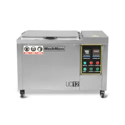
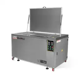
Model: UC12/UC32/UC81B/UC81A/UC110B/UC110A

1
www. mechmaxx.com
CATALOGUE
OPERATION
MANUAL
CATALOGUE
4
2.2 Requirements for operators
5
2.3 Manufacturer Safety Program
5
2.4 Liability of the user
5
2.5 Operator Responsibilities
5
2.6 Environmental Protection
6
3.1 Quick installation
6
3.2 A-type equipment liquid filling diagram
7
3.3 Installation Instructions
8
4.1 Operation process
8
4.2 Instrument settings
9
4.3 Oil-water separator (For A type)
9
4.4 Instructions for operation
10
4.5 Wrong operation reminder
14
8.1 UC12 Main circuit/control loop
15
8.2 UC32 Main circuit/control loop
16
8.3 UC81A Main circuit/control loop
18
8.4 UC81B Main circuit/control loop
19
8.5 UC110A Main circuit/control loop
21
8.6 UC110B Main circuit/control loop
6
3 INSTALL
8
4 OPERATE
11
5 FAULT ANALYSIS AND TROUBLESHOOTING
13
6 MAINTENANCE
13
7 ATTACHMENTS
14
8 CIRCUIT DIAGRAM
2.1 Safety symbols
3
2 PRECAUTIONS FOR SAFE USE
3
1.3 Working condition
3
1.2 Variety and specification
2
1.1 Equipment overview
2
1 OVERVIEW
2
2
www. mechmaxx.com
OVERVIEW
1. OVERVIEW
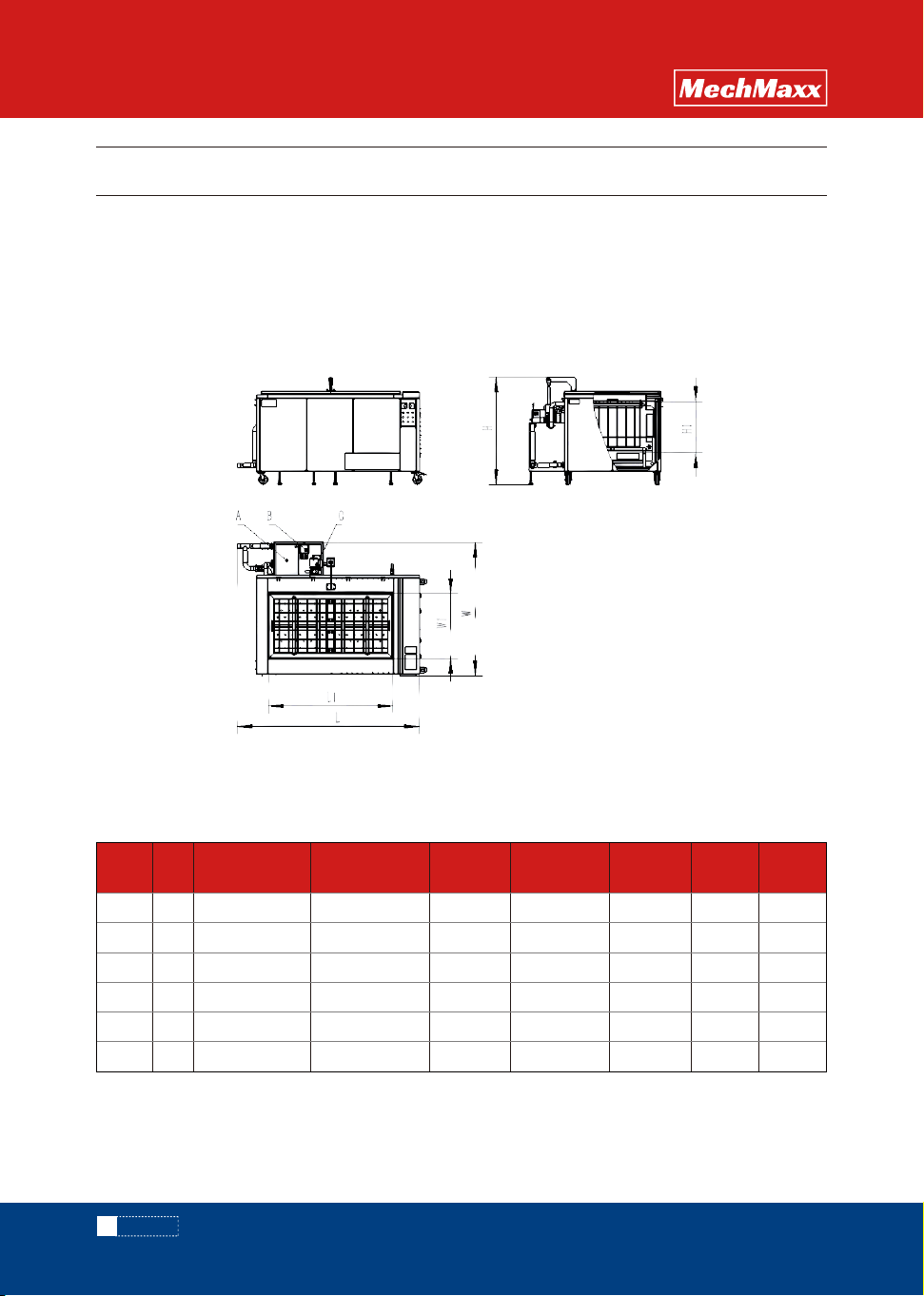
UC12 12 0.55kw 0.8kw 28khz 2.5kw Manual18×14×12
30×16×16 43×26×29 1.1kw 1.6kw 28khz 6.6kw
Manual
39×22×22 57×40×35 1.8kw 3.2kw 28khz 10kw Manual
39×22×22 57×47×35 1.8kw 3.2kw 28khz 10kw Manual
47×24×24 66×41×36 3.5kw 4.8kw 28khz 10kw
Manual
47×24×24 66×49×36 3.5kw 4.8kw 28khz 10kw Manual
33×27×23
Model Gal
Tank Size (inch)
L1×W1×H1
Ultrasonic (inch)
L×W×H
Ultrasonic
Power
Ultrasonic
Sound Power
Ultrasonic
Frequency
Heating
Opening
Method
UC32 32
UC81B 81
UC81A 81
UC110A 110
UC110B 110
OPERATION
MANUAL
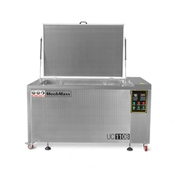
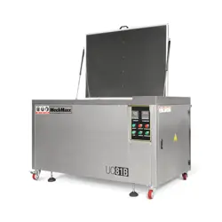
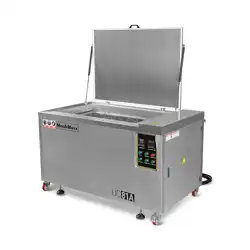
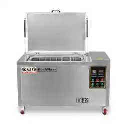
The equipment is a single-tank integrated ultrasonic cleaning machine. It uses a weak alkaline water-based cleaning
detergent. The operator puts the workpiece into the tank through the workpiece device and completes the cleaning of the
parts within the set temperature and time. It can effectively remove oil and impurities on the inner and outer surfaces of
the workpiece. The equipment is equipped with an intelligent temperature control heating system and a digital display
timing system. The equipment is simple and convenient to operate.
Explanation: Currently only A series has a water circulation system including reservoir tank, oil skimmer, and pump.
Ultrasonic cleaning machine three views
A-Reservoir tank B-Oil skimmer C-Pump
1.1 Equipment Overview
1.2 Variety and specification
3
www. mechmaxx.com
PRECAUTIONS
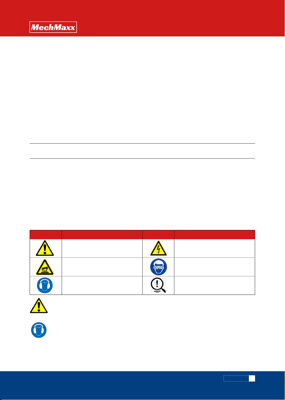
Explanation
General warning
of danger
Electric shock
hazard warning
Wear protective
glasses
Remind
Warning for hot surfaces
and heat sources
Wear ear protection
ExplanationPhoto Photo
2 . PRECAUTIONS FOR SAFE USE
OPERATION
MANUAL
◇ The installation environment must be well ventilated and free of flammable, explosive, corrosive, or conductive gases
or dust.
◇ No liquid splashing and excessive dust.
◇ Ambient humidity ≤ 80%. Ambient temperature 32 ~ 122℉.
◇ Keep away from vibration and heat sources.
◇ The foundation must not be tilted, soft or irregular
◇ Install on a solid concrete foundation and use a level to level the equipment after it is in place.
◇ There must be a reliable grounding wire connected to the equipment.
◇ The space around the equipment must be greater than 11.8in to ensure ventilation and heat dissipation.
◇ Cleaning detergent:7≤ PH ≤ 13。
◇ Detergent concentration: Please refer to the detergent manufacturer's recommendations for details.
Signal language used
Danger Danger that can lead to personal injury or death
Warning Dangerous situations that can lead to personal injury or death
Caution Danger that can lead to minor injuries
Note Danger that can lead to economic damage to the device, people and the environment
Note Important information that makes the product or warranty invalid
Information Other information that can help you understand the situation
Please follow all safety instructions on the equipment labels and in this manual.
·General safety tips
For your personal and product safety, please read the following instructions carefully before activating the device.
·If there is loud noise around the device, hearing protection measures must be worn in accordance with
relevant laws and regulations.
·Some animals may be able to sense the high-frequency noise produced by the
device. Keep pets or livestock away from the device.
1.3 Working conditions
2.1 Safety symbols
Only authorized professionals can
·Repair the device.
·Operate the device.
Otherwise the manufacturer's product warranty will become invalid.
Note
4
www. mechmaxx.com
PRECAUTIONS
OPERATION
MANUAL
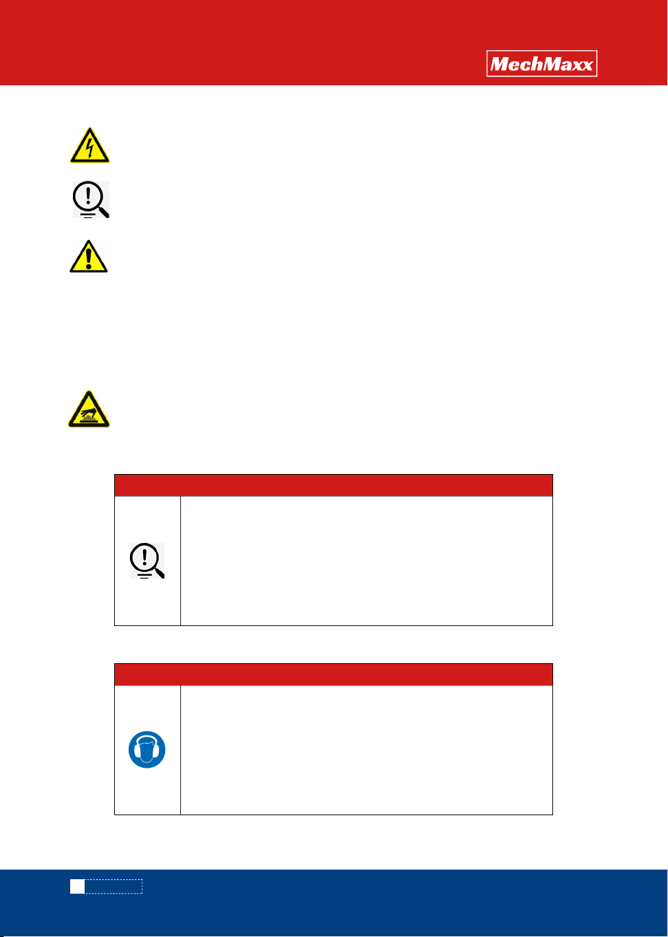
Danger of electric current
2.2 Requirements for operators
·Electrical parts such as adapter boxes and conduit pipes may come into contact with cables or high voltage
may exist due to humid working environment. Do not touch these parts after the power supply is connected to avoid
electric shock.
·Before replacing electrical components, turn off the main power and make sure the part is of the correct
specification.
·Do not touch any electrical switch with wet hands to avoid the risk of electric shock.
·Before leaving the equipment after work, be sure to turn off the main power supply.
·Do not scrape off the labels and warning signs on the machine.
·To ensure the safety and accuracy of the device, please do not hit the device.
·Danger to life if live cables or components are touched!
·Before cleaning the equipment or opening the electrical box, shut down the device and disconnect the power!
·Only authorized personnel may perform operation, repair, servicing and maintenance work.
·The grounding must be reliable to ensure the safety of personnel and machines
When the equipment or environmental noise exceeds 75Db, it may
damage hearing.
In this case, the operator requires the wearing of hearing
protection.
Note
·Be careful of burns when touching the workpiece and basket! Wear protective gloves.
5
www. mechmaxx.com
PRECAUTIONS
OPERATION
MANUAL
The design and production of the equipment refer to risk analysis, relevant international regulations and standards,
representing the latest technology to ensure safety during use.
The prerequisite for ensuring safe production is that all necessary safety measures are implemented. The development,
inspection, and implementation of safety measures are the responsibility of the buyer. The buyer needs to understand
the relevant procedures and associated risks, be responsible for the designation and assignment of personnel, and bear
ultimate responsibility for the safety of personnel and equipment.
User's responsibility:
◇ Unpacking and assembly
◇ Safety training, relevant personnel understand the basic regulations of work safety and accident prevention.
◇ Selection of cleaning scheme.
◇ The supply of water and electricity meets the requirements of equipment operation。
◇ Develop, coordinate and implement equipment maintenance.
2.4 Liability of the user
Operator's responsibility:
◇ Understand and comply with the basic regulations of work safety and accident prevention.
◇ Pay attention to relevant safety regulations and safety tips in the manufacturer's instructions.
◇ Under no circumstances should their behavior affect work safety.
◇ Wear personal protective equipment and use protective measures.
◇ Timely notify the operator of maintenance and repair equipment information.
◇ When equipment anomalies are found, report to the responsible person immediately and ask for removal.
2.5 Operator's responsibility
High temperature, steam, noise and other emissions may occur during normal operation. The operator and staff shall
comply with the protective measures and regulations of the factory. Sewage discharge shall comply with laws and
regulations related to environmental protection.
2.6 Environmental protection
2.3 Manufacturer Safety Program
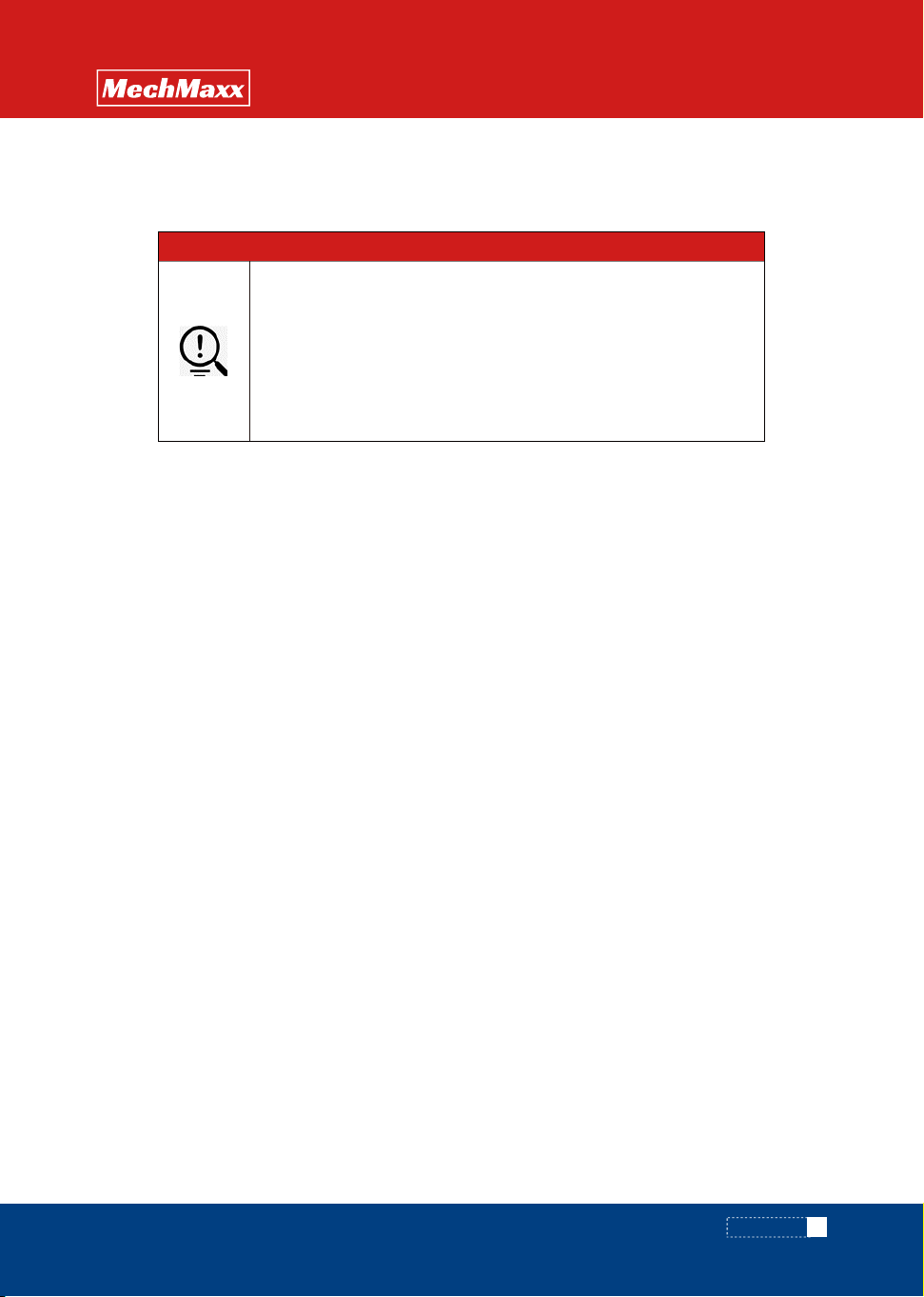
Please observe the warnings displayed on the device.
Do not make any unauthorized changes to the device.
The electrical and mechanical properties of the device may be
altered and affected.
Note
3. INSTALL
6
www. mechmaxx.com
INSTALL
OPERATION
MANUAL
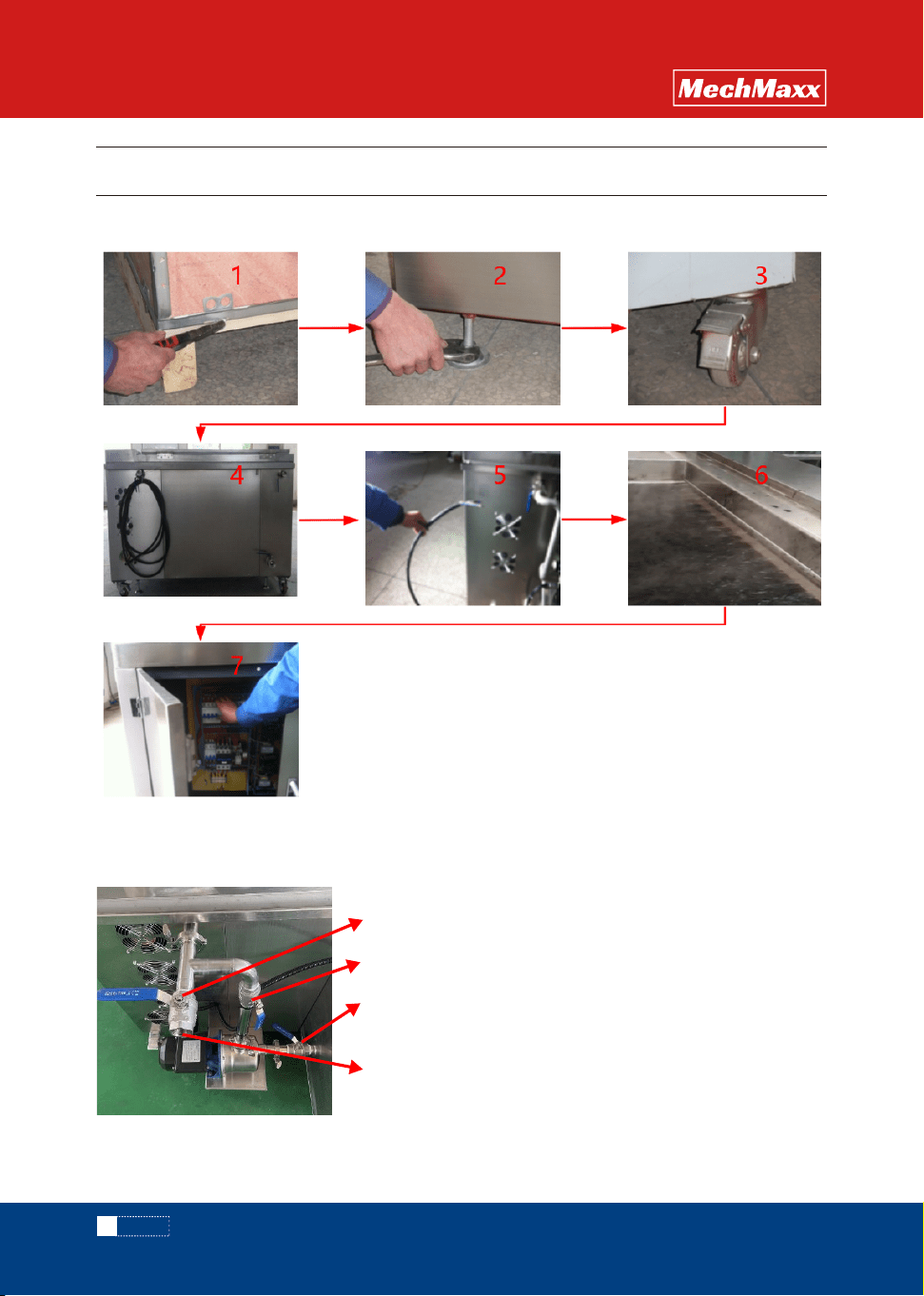
After the workpiece to be cleaned is put into the
cleaning tank, the valve 1 is opened, the valve 2 is
closed, and the water is supplied through the pipe
connected to the water inlet. After the water is added,
the valve 2 can be opened to work. Valve 3 is used to
control the water intake of the pump port. Do not close
the valve, and adjust it to the appropriate Angle as
shown in the figure to ensure the balance between the
water intake and overflow of the cleaning tank, so as to
avoid water overflow of the cleaning tank during the
cycle.
3.1 Quick installation
Valve 1
Valve 2
Valve 3
intake
3.2 Liquid filling of type A equipment

7
www. mechmaxx.com
INSTALL
OPERATION
MANUAL
3.3.1 Open box
◇ Before unpacking, check the appearance for obvious damage. If yes, please take photos in time and keep them, and
contact the supplier immediately.
◇ Open the corresponding latch from the bottom and open the wooden case properly to avoid damage to the internal
equipment caused by violent unpacking.
◇ Do not move the device directly when there is a heavy load in the tank or the tank is filled with liquid. Otherwise, the
casters may be damaged.
3.3.4 Pipe connection
◇ Connect water intakes, overflow , and drain according to the labels
◇ Ensure that the overflow port is normally open;For special cases, if it is necessary to increase the effective
cleaning height, close the overflow port, but special attention needs to be paid to liquid overflow;
3.3.5 External power connection
◇ Connect the device accurately according to the voltage indicated on the device nameplate;
◇ If phase sequence protection is installed on the device, the phase sequence may be inconsistent. Adjust the phase
sequence to work normally;
3.3.6 Add water
◇ When adding water to the tank, ensure that the drain is closed, and pay attention to whether the tank leaks, if any,
stop in time;
◇ When adding liquid to the type A cleaner, ensure that the liquid is injected according to the valve status as shown in
the figure above. When injecting liquid for the first time, ensure that the liquid reservoir tank is filled with at least half
of the liquid volume.
◇ Do not add hot water above 176 ° F directly.
3.3.7 Power on
◇ Use a dedicated tool to verify that the power supply is correctly connected before powering on the system;
After the power-on, if no power indicator is displayed, the phase sequence of the power supply may be inconsistent.
You can adjust the phase sequence
3.3.8 Other instructions
◇ For some models equipped with pneumatic door opening, external compressed air power is required, please connect
according to the instructions, and the access air pressure must be ≥0.5Mpa/cm2; The opening and closing speed is
adjusted by the needle valve at the inlet and outlet of the cylinder.
◇ Before using the equipment, read the operating instructions carefully to understand the structure and performance
of the equipment and be familiar with the requirements for operation, adjustment, lubrication, and maintenance of the
equipment to avoid damage to the equipment.
3.3.2 Horizontal adjustment
◇ Usethetightening tool and level to adjust the level;
◇ Makesurethe brakes are locked for moving wheels of the same height;
3.3.3 Brake lock
◇ Ensurethat the brakes are locked when the device is in use;
3.3 Installation instructions
8
www. mechmaxx.com
OPERATION
OPERATION
MANUAL
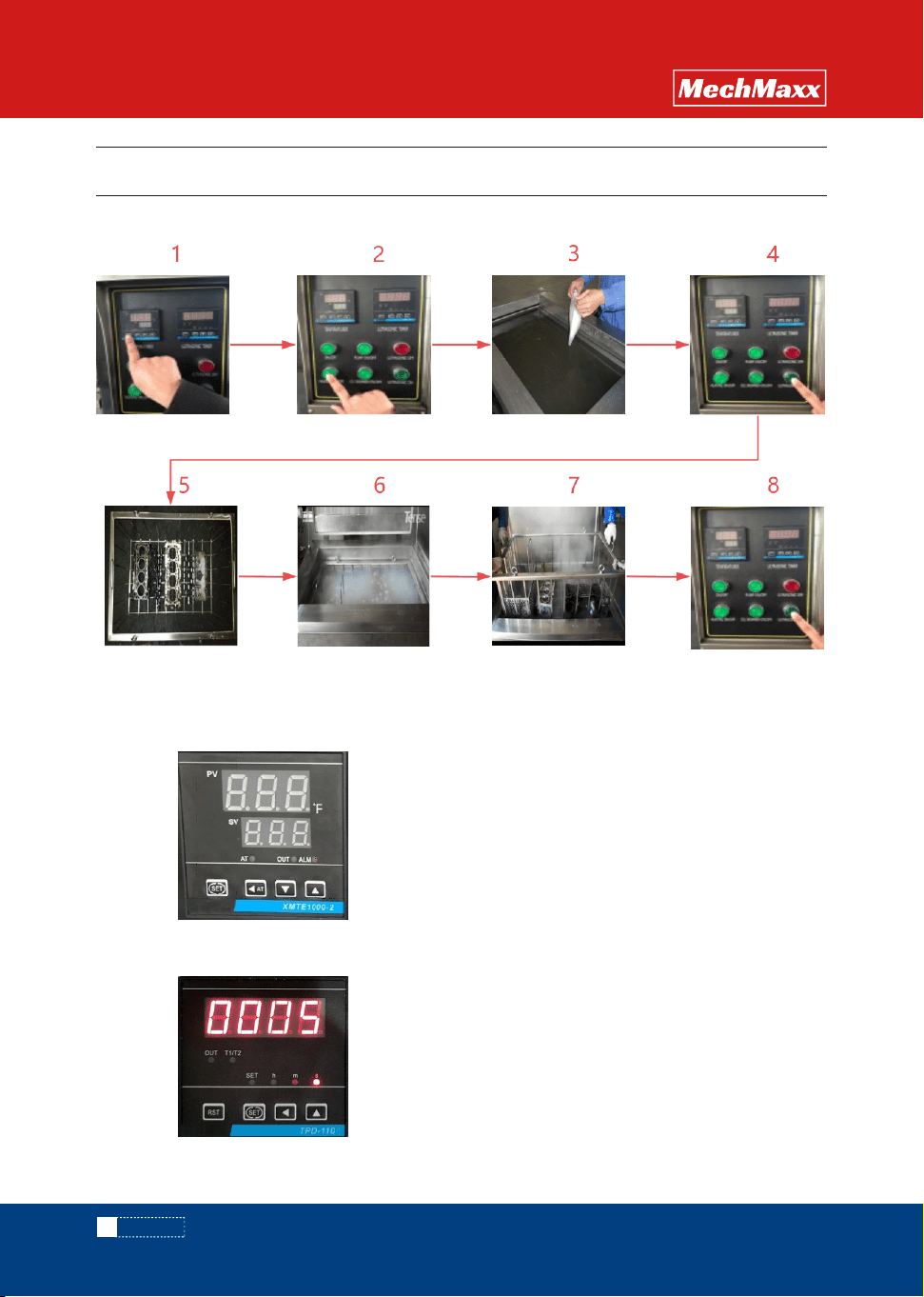
Step 1: First press the "set" key once, the working temperature
display "SP";
selection;
Step 2:touch“”movable,touch“▲”and“▼”for numerical;
Step 3:Touch“SET”again,Set parameters complete, exit.
Step 1: press "set" key once first;
Step 2: touch "" shift, touch "▲" for numerical selection.
Step 3: Tap the "SET" button again to complete the parameter
setting and exit.
4.1 Opertion process
4.2 Instrument setting
4. OPERATION
Work temperature:
4.2.1 Thermometer setting
4.2.2 Time setting
Setting temperature:
Working time:
9
www. mechmaxx.com
OPERATION
OPERATION
MANUAL
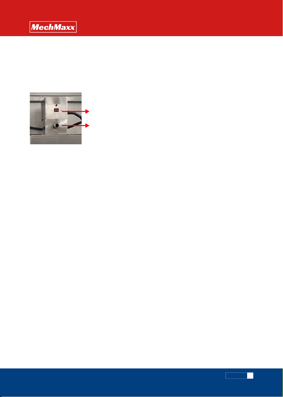
Thisfunction is used to deal with excessive oil slicks after cleaning, thereby reducing the secondary pollution of parts
and extending the service life of the cleaning agent;
◇ Start the circulating pump and ensure that the valve between the cleaning tank and the liquid storage tank is open
before operation;
◇ Thisfunction is turned on regularly, or work for 2-3 minutes after each cleaning and before the parts are removed;
◇ After the oil skimmer switch is turned on, the oil will flow out from the sewage outlet.
4.3 Oil skimmer (TYPEACLEANER)
4.4 Procedure Description
4.4.1 Specification setting
◇ Temperature setting maximum temperature should not exceed 146℉; Working at high temperature for a long time
is easy to cause the transducer to fall off.
◇ The schedule can be set in seconds, minutes, and hours. The factory default unit is second.
◇ The second startup uses the same parameters as the previous startup.
4.4.2 Turn heating
If the cleaning detergent is selected in powder form; In order to fully dissolve the powder detergent, heat the temperature
to about 86-95℉ before adding the detergent. For liquid cleaning detergent, there is no need to heat in advance.
4.4.3 Add cleaning detergent
◇ Do not turn on the ultrasonic when adding the cleaning agent;
◇ Add the cleaning detergent according to the specified process concentration. After adding, stir the liquid through a
tool to ensure that the cleaning agent is dissolved thoroughly;
◇ Use detergent with PH< 7 with caution and evaluate the MSDS characteristics of the detergent.
4.4.4 Turn on ultrasonic
◇ At this stage, the ultrasonic wave is turned on to dissolve the cleaning agent more thoroughly, and the liquid degassing
treatment can also be carried out, which is conducive to the cleaning effect;
◇ During the period, you may hear a harsh screaming sound, which is normal, when you put in other parts or baskets,
the sound will automatically disappear;
4.4.5 Parts placement
◇ Parts can not be directly into the cleaning tank for cleaning, must be through the tooling basket;
◇ Parts placement comply with the principle: no overweight, no excess, less superposition principle.
4.4.6 Cleaning
◇ Make sure the ultrasonic is off when the parts are put into the cleaning tank;
◇ After the parts are put in, the liquid is basically stable and the ultrasonic wave is turned on for cleaning;
◇ High temperature liquid injection during cleaning may cause burns, please wear appropriate labor protection
products;
◇ Avoid stirring the liquid during cleaning;
OIL SKIMMER ON/OFF
Drain
10
www. mechmaxx.com
OPERATION
OPERATION
MANUAL
4.5 wrong operation alerts
4.4.7 Take out parts
◇ The parts are removed by taking out the basket;
◇ When taking out, turn off the ultrasound first;
4.4.8 Turn off
◇ If it is determined that the equipment will be shut down for a long time, please turn off the power after turning off
the ultrasonic and heating; Close the water inlet valve at the same time;
◇ If the shutdown is only for a short time (within 1 hour), please turn off the ultrasound;
Correct operation
1)Heating pipe dry burning, short
circuit occurred;
2)The ultrasonic transducer is
damaged
Add liqulid in time
1)Heating pipe dry burning, short
circuit occurred;
2)The ultrasonic transducer is
damaged
Damage to the machine is more
serious, and even easy to
produce personal safety injuries
After troubleshooting and
checking, confirm that the
device is working normally
Water flooding below 122 ° FThe transducer is easy to fall off
Use high temperature liquid to
pour directly into the cleaning
tank
Continue to run the equipment
when the cleaning solution is
insufficient
Ignore the abnormal status of
the device and continue to run
The liquid must exceed the
position above the side
ultrasonic plate
Start the device first and then
add the cleaning liquid
Consequence statementError operation

11
www. mechmaxx.com
FAULT ANALYSIS
OPERATION
MANUAL
Solution
The front-end circuit breaker or
power cable has small
specifications
The temperature control meter
shows 000, and the contactor
does not draw
Temperature indicator normal,
contactor suction
Ultrasonic power failure
Heating pipe leakage
Loose thread
Phase sequence error -- change
the position of any two phase
lines of the power supply inlet
line; Check whether the neutral
line is connected
The phase sequence is
wrong, or the cleaner is not
connected to the neutral line
No response when the power
switch is turned on
Button failure
Replace the incoming leakage
circuit breaker or power
conductor
Check whether the heating
circuit breaker is tripping, if
tripping can be re-closed;
If there is no trip, use the test
pen to test the lower end screw
of the heating contactor, if there
is electricity, replace the
heating tube
Open the left sealing plate and
check whether the sensor cable
is disconnected. If it is
disconnected, reconnect it. If it
is not disconnected, replace the
temperature sensor
Open the ultrasonic safety one
by one, test separately,
corresponding to a set of safety
trip, indicating that the
corresponding ultrasonic power
supply is damaged. Contact the
manufacturer
Turn off the power, remove the
heating tube connection cable,
and power on to confirm
whether the trip is made. The
corresponding trip heating tube
is the damaged heating tube
and can be replaced
Re-tighten the screws related to
it according to the drawing
A trip occurs when the power
switch is activated
Activate ultrasonic trip
Unheated
Trip when heating on
Fault causeFault phenomenon
5. FAULT ANALYSIS AND TROUBLESHOOTING
12
www. mechmaxx.com
FAULT ANALYSIS
OPERATION
MANUAL
Solution
Check whether the circuit
breaker or contactor is burned
out
The pressure belt screws are
loose
Motor failure
The circulating pump's own
filter or filter is blocked
The circulating pump shaft is
rusty
Could be a set of ultrasound
damage
The cleaning liqulid is too dirty
Low temperature, no exhaust
The electric pen is used to test
whether the three phases at the
input end of the heating tube in
the electric box have electricity,
and the clamp meter is used to
measure the current of the
heating tube. If there is no
current in one phase, it
indicates that the heating tube
is broken and can be replaced
with a new one.
No burn marks
If there is a burn out, replace
the circuit breaker or contactor
Adjust the steel belt press
screws
Replace the filter and remove
the fault
After the replacement is still
faulty, open the circulation
pump inlet pipe connection to
clean the filter screen
Start the oil scraper with an
electric pen to test the terminal
of the oil scraper. If there is
electricity, the oil scraper does
not turn, and the oil scraper can
be replaced
Start the ultrasound, see if there
is a red light, if so, please
contact the manufacturer
When the temperature reaches,
exhaust gas is completed and
then cleaned
Change the cleaning liqulid
Clean shaft
It was heating up normally, and
suddenly it's slowing down
The oil scraper machine does
not turn, the contactor or relay
is in the drawn state, and the
circuit breaker does not trip
The oil scraper does not turn
the steel belt
Circulation pump does not turn
water or water is very small
Circulating pump does not turn
humming
Poor cleaning effect
Fault causeFault phenomenon

13
www. mechmaxx.com
MAINTENANCE AND REPAIR / ATTACHMENTS
OPERATION
MANUAL
Every quarter
Clean the heating tube covering
Check whether indicating components
such as the liquid level sensor and
pressure gauge are normal
Check whether the tooling is damaged
or deformed. If it is damaged, it is
forbidden to go online
Replace the cleaning medium to
prevent deterioration
Check whether pipes leak and handle
them in time
Regularly check the alarm and various
key functions, regularly check whether
the wiring terminals are loose, and do
fastening
Basket
Manual 1pc
1pc
Cleaning tank
Every weekItem cycle
6. MAINTENANCE AND REPAIR
7. ATTACHMENTS
√
√
√
√
√
√
√
Item cycle Quantity
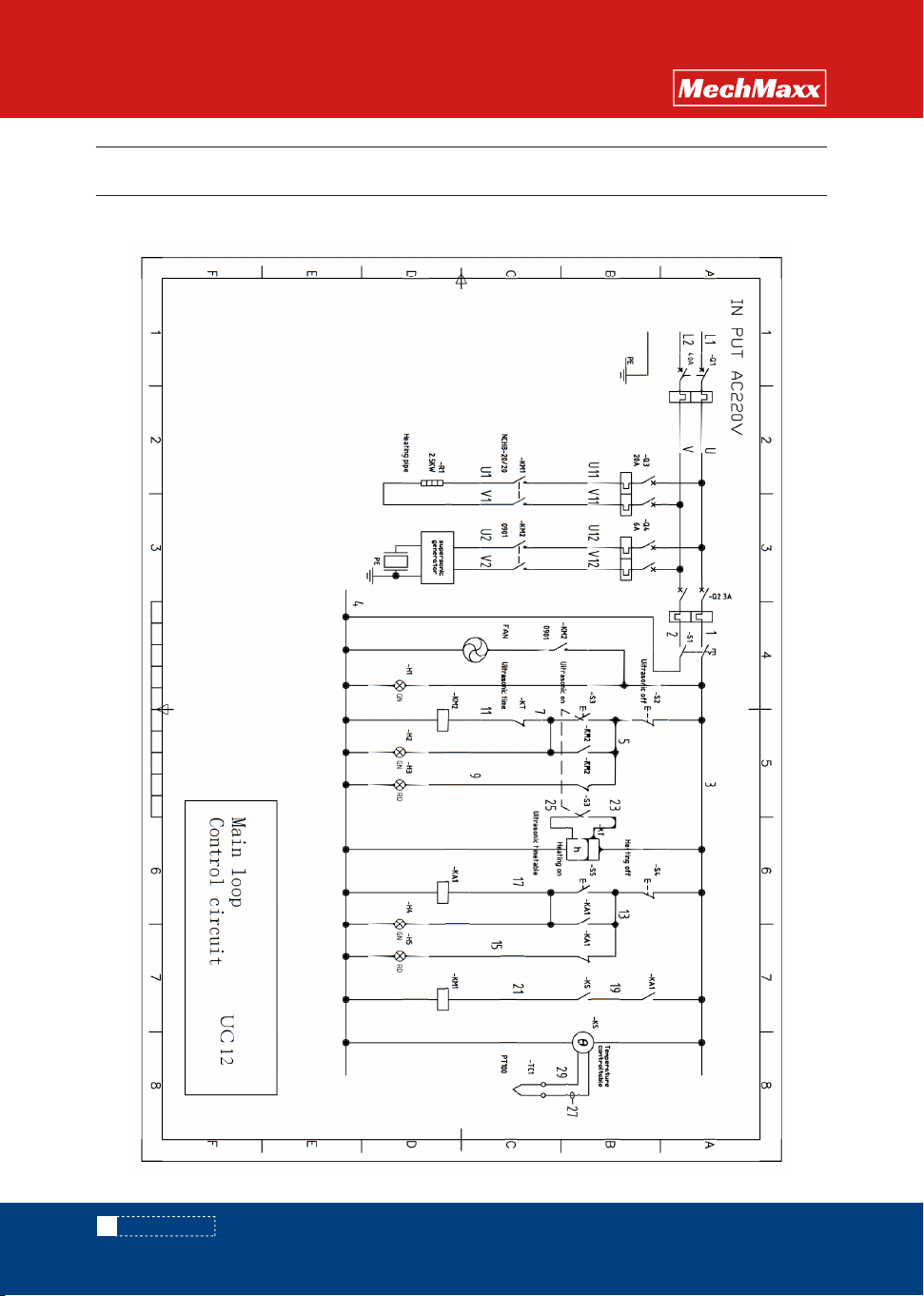
8.1 UC12 Main loop/control loop
14
www. mechmaxx.com
CIRCUIT DIAGRAM
OPERATION
MANUAL
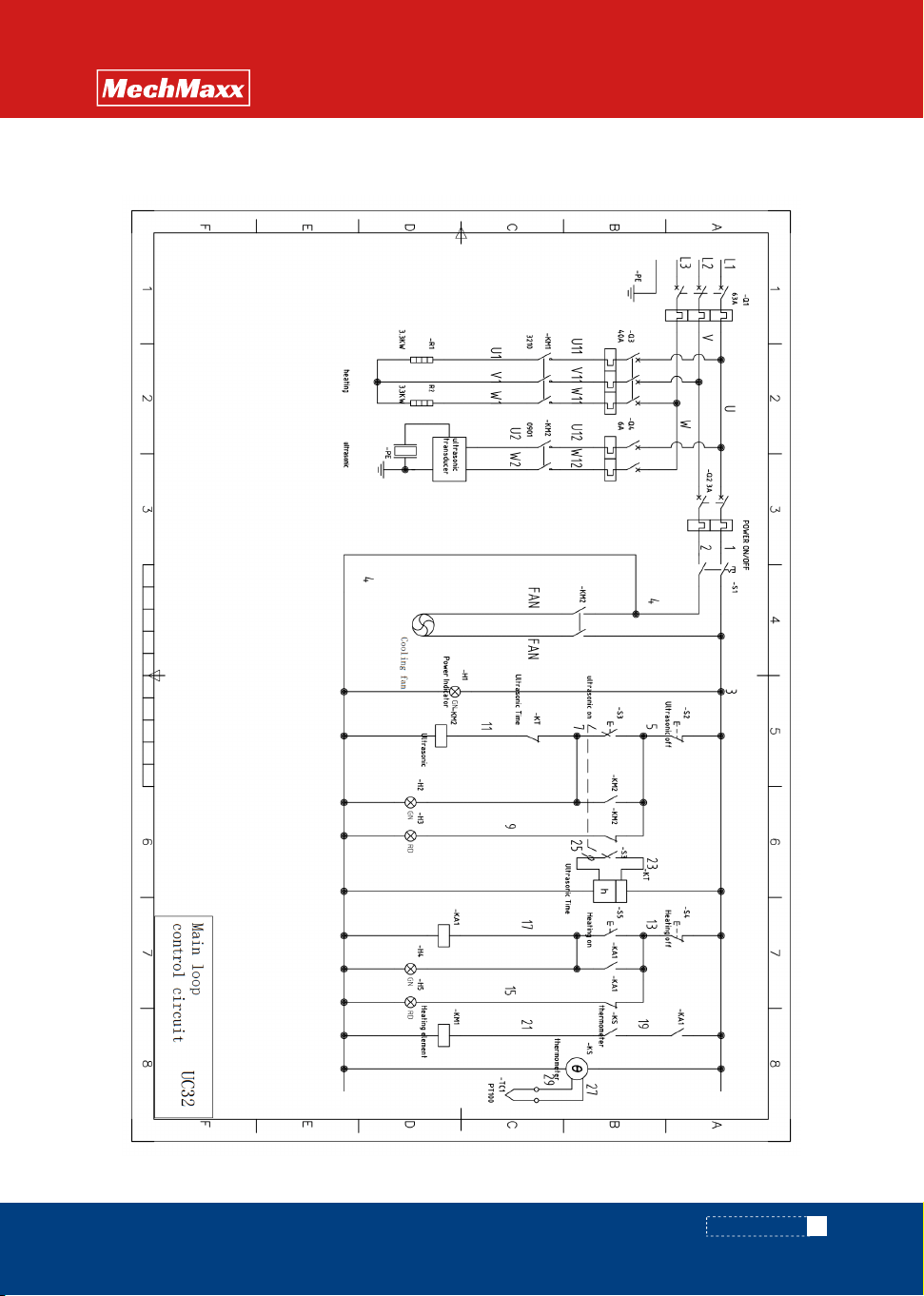
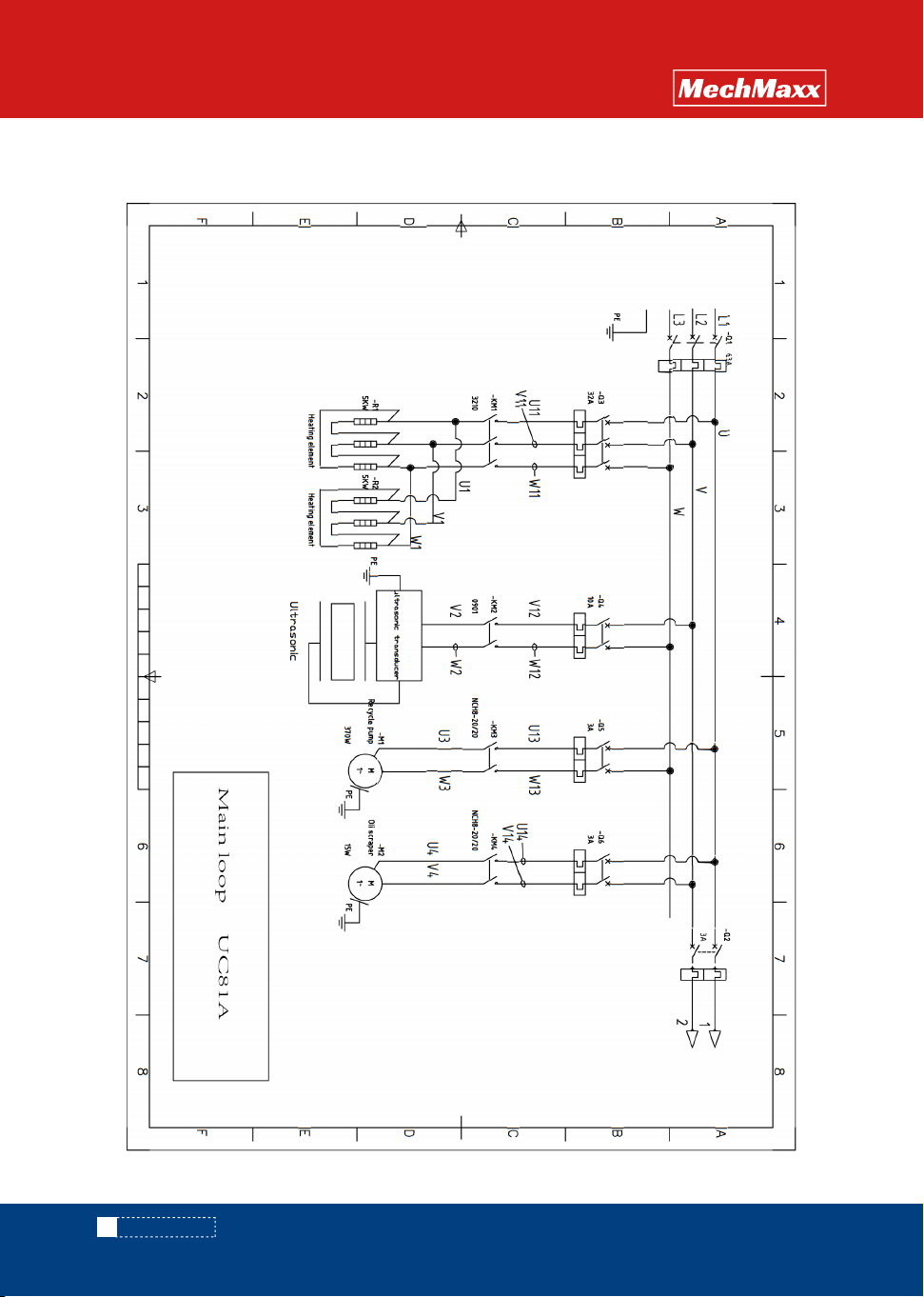
8. CIRCUIT DIAGRAM
15
www. mechmaxx.com
CIRCUIT DIAGRAM
OPERATION
MANUAL
8.2 UC32 Main loop/control loop
16
www. mechmaxx.com
CIRCUIT DIAGRAM
OPERATION
MANUAL
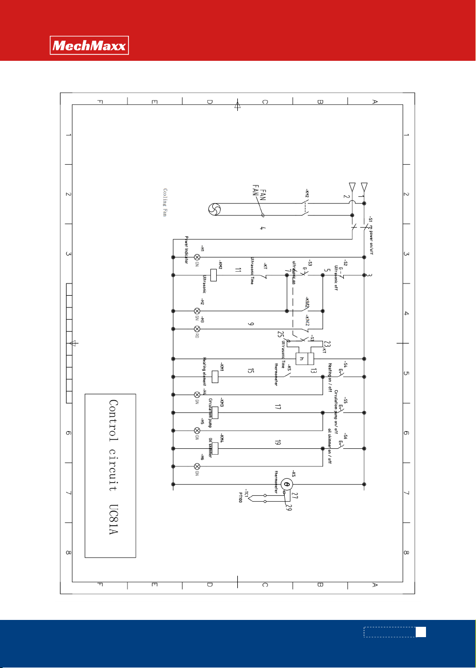
8.3 UC81A Main loop/control loop
17
www. mechmaxx.com
CIRCUIT DIAGRAM
OPERATION
MANUAL
18
www. mechmaxx.com
CIRCUIT DIAGRAM
OPERATION
MANUAL
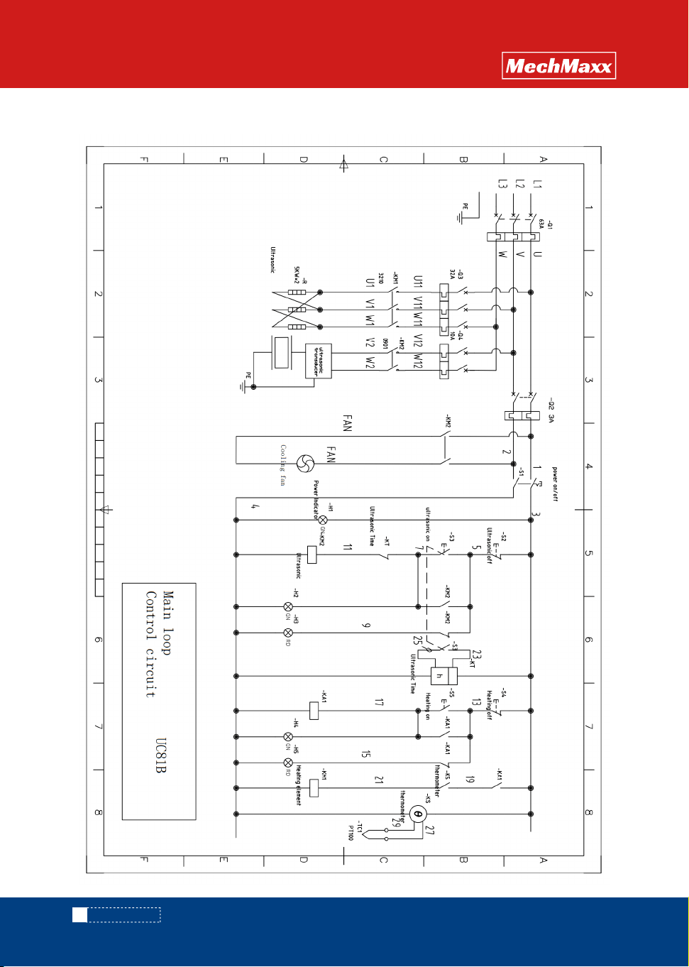
8.4 UC81B Main loop/control loop
19
www. mechmaxx.com
CIRCUIT DIAGRAM
OPERATION
MANUAL
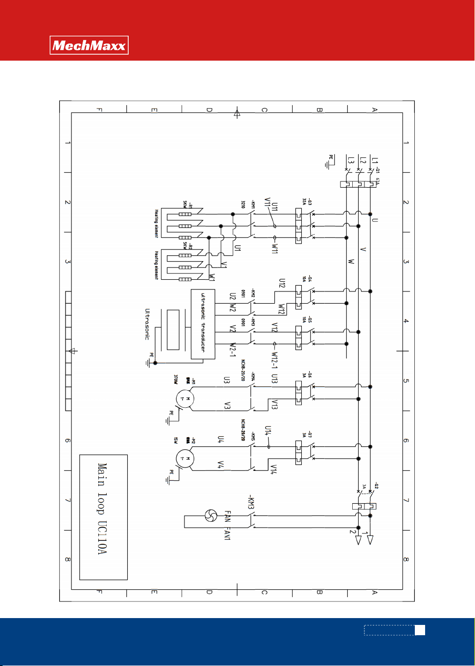
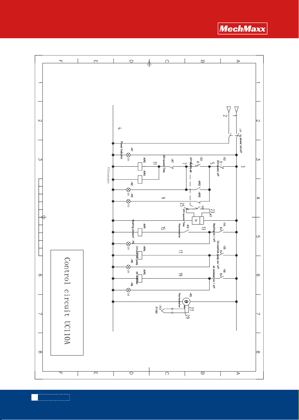
8.5 UC110A Main loop/control loop
20
www. mechmaxx.com
CIRCUIT DIAGRAM
OPERATION
MANUAL
www. mechmaxx.com
CIRCUIT DIAGRAM
OPERATION
MANUAL
21
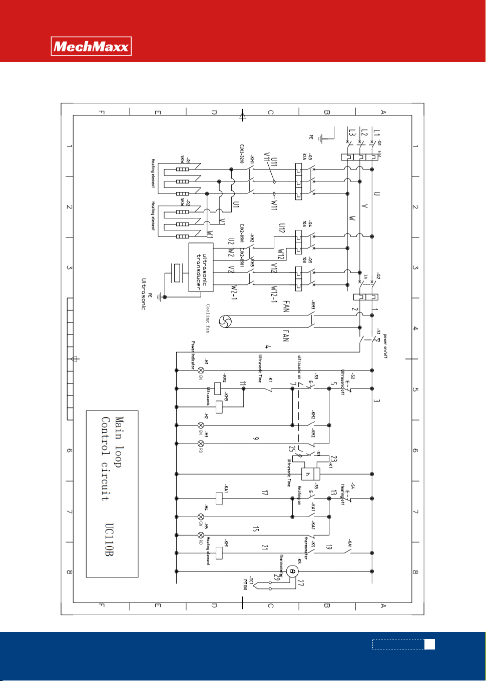
8.6 UC110B Main loop/control loop