1
CISSCA User's Manual
V3.1: December 2022
About CISSCA
Commercial Installation Solutions Speaker Calculator (CISSCA) is a simulation software application
into which conditions including the size and application of the room in which speakers are to be
situated, and the type and arrangement of speakers are input, enabling rapid estimation of the optimal
numbers of speakers and confirmation of the virtual sound pressure values in the estimated results.
If you wish to specify conditions in more detail, please use Yamaha's Y-S3 audio simulation software.

2
Terms of Use of the Software
Yamaha Corporation (hereafter referred to as Yamaha) has established a software license
agreement regarding the use of this software and after-sales services. You are permitted to use this
software only if you agree to the Terms of Use outlined below.
Before use of this software, please ensure you read these terms and conditions carefully. Enabling
this software (including, but not limited to downloading, installation, or other actions) shall be construed
as your agreement with the Terms of Use. If you do not agree with these Terms of Use, then cease
download or installation and/or delete the software files.
Software License Agreement
・ Copyright and License
Yamaha grants you the rights to use the software program and data files comprising this software
as well as future update programs and data files that may be distributed to you under certain conditions
(hereafter referred to as “the Software”) only on computers, musical instruments, or devices that you
own or manage.
The rights to the recorded media recorded using the Software belong to you, but the rights to the
Software itself and its copyright belong to Yamaha and/or its licensers.
・ Restrictions on Use
The Software contains copyrighted information, and in order to protect this, you may not reverse
compile, reverse assemble, reverse engineer, or otherwise reduce the software to human readable
form.
You may not duplicate in whole or in part, modify, rent, lease, resell, or distribute the Software or
make derivative works based on the contents of the Software.
You may not transfer the Software to another PC over a network.
It is not permitted to use copyrighted music tracks available through the use of this Software for
commercial purposes, to reproduce, transmit, distribute, play, or perform these to an unspecified
number of people without the permission of the copyright holder, to remove encryption from available
data without the permission of the copyright holder, or to modify digital watermarks.
Furthermore, you may not distribute illegal data or data that is contrary to public order or morality
using the Software, nor establish services that use the Software without Yamaha's written permission.
・ Termination
In regard to the license in these Terms of Use, if you infringe or violate any copyright laws or any of
the terms and conditions of this agreement, the license shall be terminated even if Yamaha does not
send you a notice to that effect.
In such a case, you must destroy the Software as well as any copies thereof.
・ Warranty of this Product
If the Software does not demonstrate the prescribed functionality or has other issues,
you may redownload and/or reinstall the Software.
Yamaha offers no warranty beyond this.
You shall bear all risks regarding the quality and performance of the Software. In no event shall
Yamaha be liable for the storage or management of this Software after your acquisition of such.
In no event shall Yamaha be liable for providing you with the acquired Software again in the event
of its loss, regardless of the reason for said loss.
・ Limitation of Liability
In no event shall Yamaha be liable for any direct, consequential, incidental or indirect damages
whatsoever (including, without limitation, lost data, lost profits, business interruption, and lost business
information) resulting from the use of or inability to use the Software, even if Yamaha has been advised
of the possibility of such damages, or if there may be claims for compensation by a third party,
regardless of whether these damages are normal or special.
・ Third Party Software
Yamaha may provide third party software programs, data files and related documentation (hereafter

3
referred to as Third Party Software) along with the Software.
If there is a statement in the manual accompanying the Software that indicates that other provisions
shall be observed, those provisions shall be observed regardless of the terms and conditions in this
agreement. However, the following provisions shall apply in regard to Yamaha's after-sales services
and warranty.
Yamaha will not provide after-sales services regarding the operation of Third Party Software, defects
in Third Party Software, or other matters related to Third Party Software.
Yamaha disclaims all warranties, express and implied, including, but not limited to warranties of
Third Party Software's merchantability and fitness for a particular use.
You shall bear all risks arising from the use and the functions of Third Party Software.
In no event shall Yamaha be liable for any direct, consequential, incidental, or indirect damages
whatsoever (including, without limitation, lost data, lost profits, business interruption, and lost business
information) resulting from the use of or inability to use Third Party Software, even if Yamaha has been
advised of the possibility of such damages, regardless of whether these damages are normal or
special.
・ U.S. GOVERNMENT RESTRICTED RIGHTS NOTICE: Restrictions for when the user is the
United States Government or related organization
The Software is a "commercial item," as that term is defined at 48 C.F.R. 2.101 (Oct 1995),
consisting of "commercial computer software" and "commercial computer software documentation,"
as such terms are used in 48 C.F.R. 12.212 (Sept 1995). Consistent with 48 C.F.R. 12.212 and 48
C.F.R. 227.7202-1 through 227.72024 (June 1995), all U.S. Government End Users shall acquire the
Software with only those rights set forth herein.
In these conditions, the phrasing "the Software" refers to the Software defined in this Agreement.
・ General Terms
This agreement shall be governed by and construed in accordance with the laws of Japan. All
disputes that may arise between you and Yamaha concerning this License Agreement shall be settled
under the jurisdiction of the Tokyo District Court.
Version information
V3.1
·Supported speakers added
Ceiling speaker: VXC2F, VC4, VC6, VC8, VC4N, VC6N, VC8N
Subwoofer: VXC8S
·Subwoofer arrangement available locations increased from 2 to 9.
·Screen layout revised
·Supported speakers
Ceiling speaker: VXC4, VXC6, VXC8, VXC2F, VXC3F, VXC5F, S5*, NS-IC400, NS-IC600,
NS-IC800, VC4, VC6, VC8, VC4N, VC6N, VC8N
Surface mount speaker: VXS5, VXS8, VXS3F, VXS3FT, VXS1ML, VS4, VS6, S15, S55,
NS-AW392, NS-AW592, NS-AW992
Subwoofer: VXS10S, VXS10ST, VXS3S, VXC8S
4
File compatibility with previous versions
Version 2.1: No compatibility
Version 3.0: Reading and sound pressure calculations for files created in Version 3.0 available.
Files created with Version 3.1 are not compatible with Version 3.0.
Sound pressure cannot be calculated for files that use added speaker data.
The impedance setting is unified with the setting of the ceiling speaker.
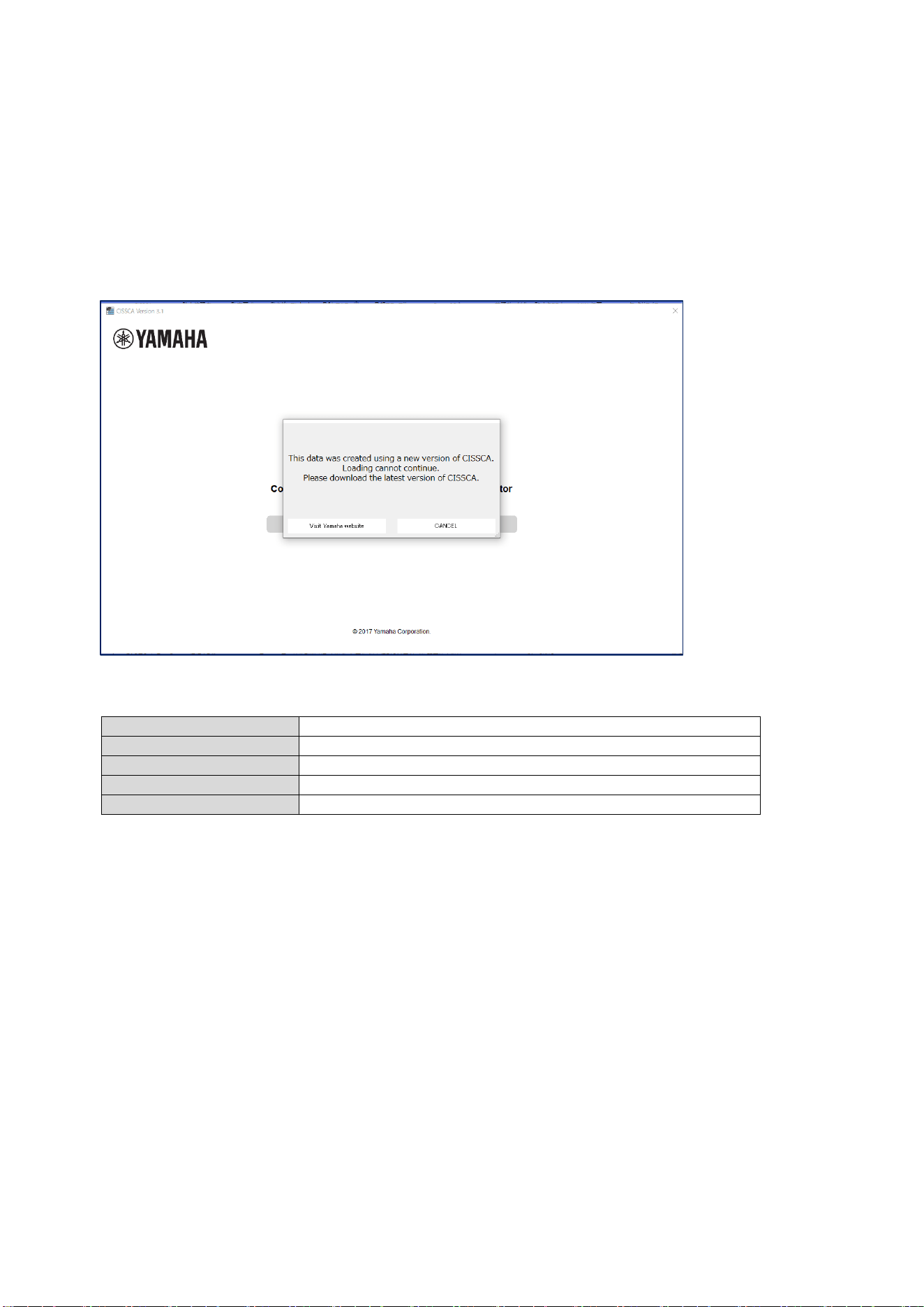
File compatibility with future versions
It is not compatible with newer versions that will ship in the future.
If the following message is displayed when reading the file, please use the latest version of CISSCA.
PC System Requirements
OS
Windows 7 / 8 / 8.1 / 10 / 11 (Framework 4.5 or above)
CPU
32 or 64-bit processor, 1 GHz or above
Memory
2 GB RAM (32 bit) or 4 GB RAM (64 bit)
Hard disk
250 MB or more free space
Display
1024×768 pixels, 256 colors or more
Install the Software
1. Double-click the "CISSCA" folder.
2. Double-click the installer file named CISSCA.
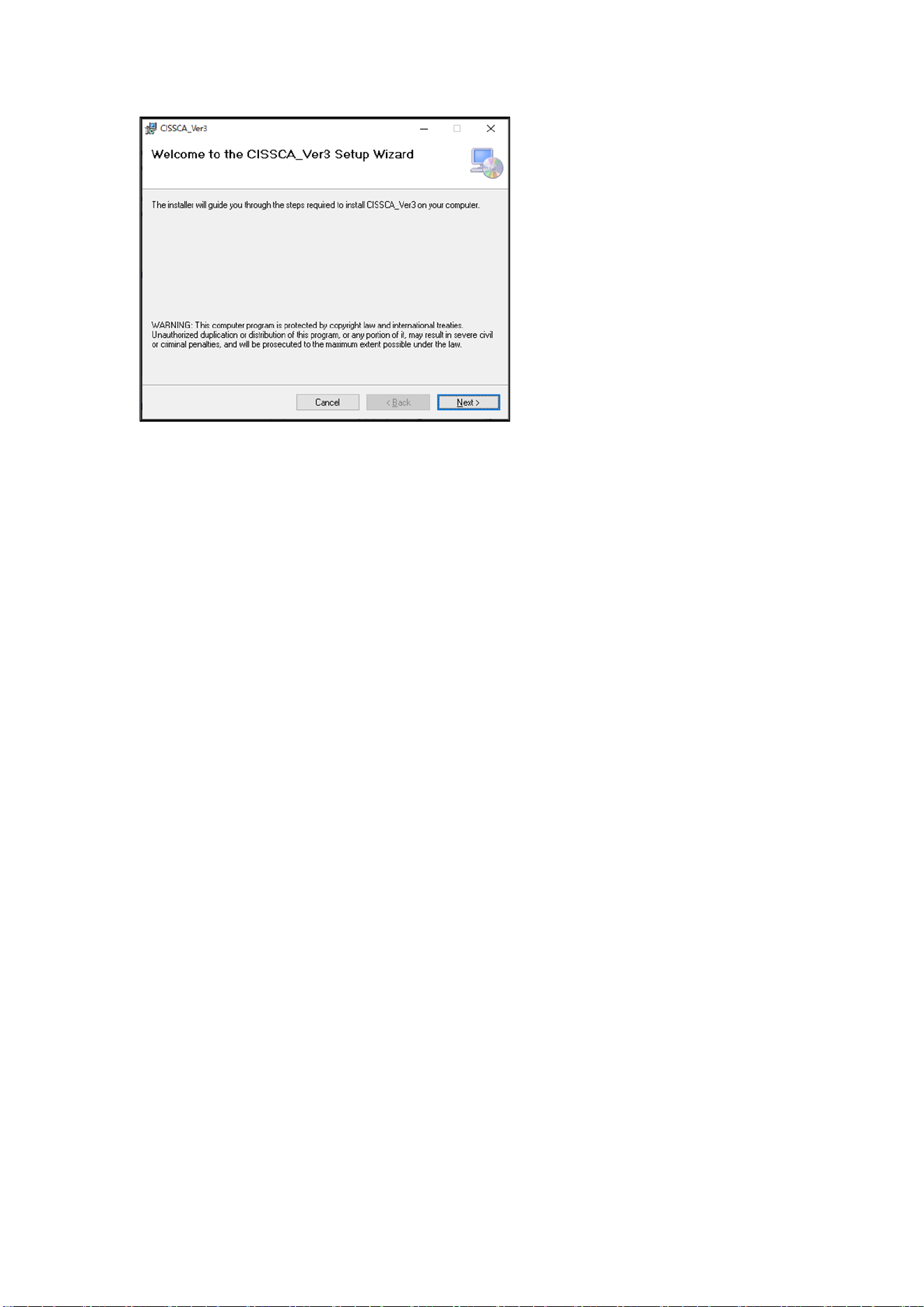
5
3. The CISSCA setup dialog box appears.
4. Follow the instructions on the screen to install the program.
5. During installation, a folder named "CISSCA" is created on the PC (in "Program
Files(x86)\YAMAHA\CISSCA_Ver3" by default).
6. Shortcuts are added to the Start menu and desktop.
Uninstall the Software
1. Click "Start" > "Settings" > "Control Panel" > "Add or Remove Programs".
2. The "Add or Remove Programs" dialog box appears.
3. Click the "Remove" button for CISSCA.
4. A dialog box will appear. Follow the instructions on the screen to uninstall the program.

6
Index of Contents
About CISSCA ....................................................................................................................................... 1
Version information ................................................................................................................................ 3
File compatibility with previous versions ............................................................................................... 4
File compatibility with future versions.................................................................................................... 4
PC System Requirements ..................................................................................................................... 4
Install the Software ................................................................................................................................ 4
Uninstall the Software ........................................................................................................................... 5
1. Starting CISSCA ................................................................................................................................ 7
1-1. Screen Operations...................................................................................................................... 7
1-2. Creating a Project ....................................................................................................................... 8
1-3. Editing a Project ......................................................................................................................... 9
1-4. Common Features ...................................................................................................................... 9
2. Data Entry ........................................................................................................................................ 10
2-1. Entering Room Conditions ....................................................................................................... 10
2-2. Configuring Speaker Density.................................................................................................... 12
2-3. Selecting the Speaker .............................................................................................................. 13
2-4. Configuring the Application....................................................................................................... 14
2-5. Adjusting Speaker Output ......................................................................................................... 16
2-5-1. Ceiling speakers ................................................................................................................ 16
2-5-2. Surface mount speakers .................................................................................................... 19
2-5-3. Subwoofers ........................................................................................................................ 20
2-6. Viewing Settings ....................................................................................................................... 21
2-7. Viewing Results ........................................................................................................................ 22
2-8. Generating Reports .................................................................................................................. 24
7
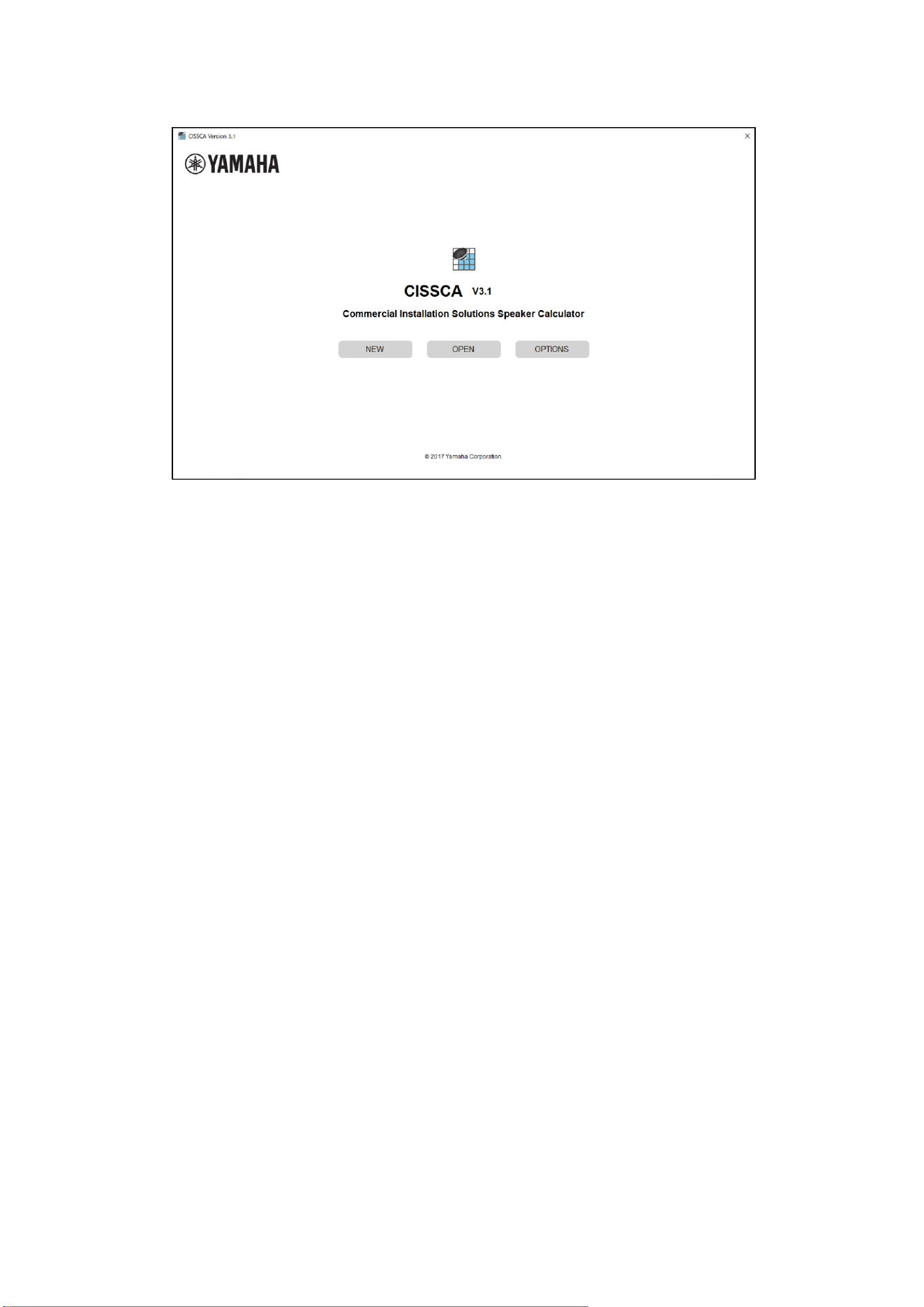
1. Starting CISSCA
To start the program, double-click the CISSCA icon on the desktop, or click "Programs" > "YAMAHA"
> "CISSCA_Ver3" from the Start menu. When the program starts, the initial screen (HOME screen)
appears.
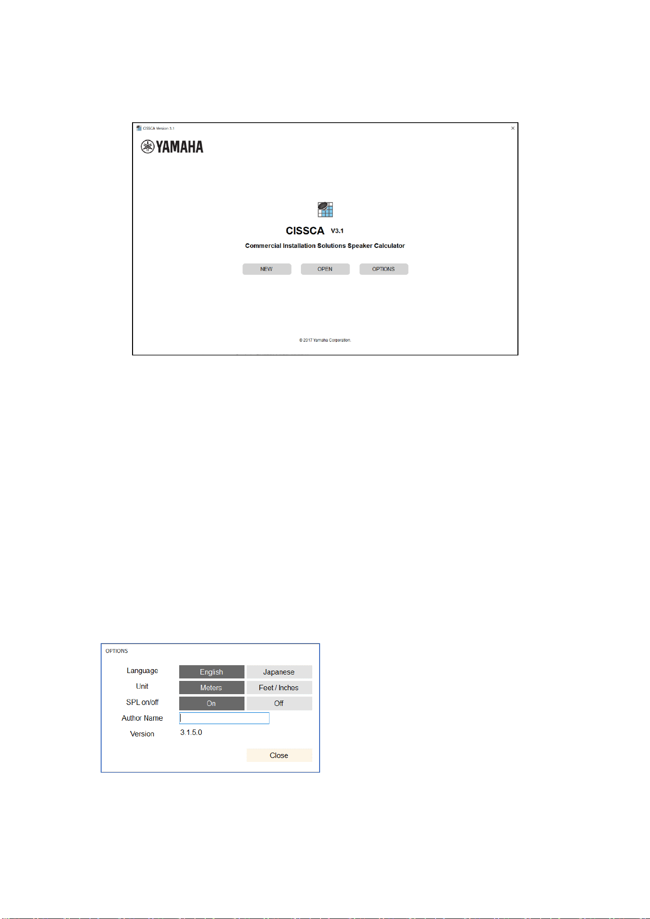
HOME screen
CISSCA is designed in a wizard format. From the HOME screen, you can simply enter conditions to
specify the number of speakers and other design parameters. A design for a single room is referred
to as a "project", and can be managed like a file.
1-1. Screen Operations
CISSCA can be used to perform the following operations from the initial screen.
・ Create a New Project: NEW
Creates a new project.
・ Open an Existing Project: OPEN
Opens a project that has been created in the past. You can also use this function to create a
new project based on a past project.
・ Configure settings: OPTION
You can set various CISSCA options.
・ Language: Select the language to use in the
CISSCA screens. You can select English or
Japanese.
・ Unit: Set the unit of measure. You can select
meters or inches.
・ SPL on/off: Select whether to show or hide the
sound pressure color map on page 4.
・ Author Name: Set the name of the author that
is indicated in reports.
・ Version: The CISSCA version number.
8
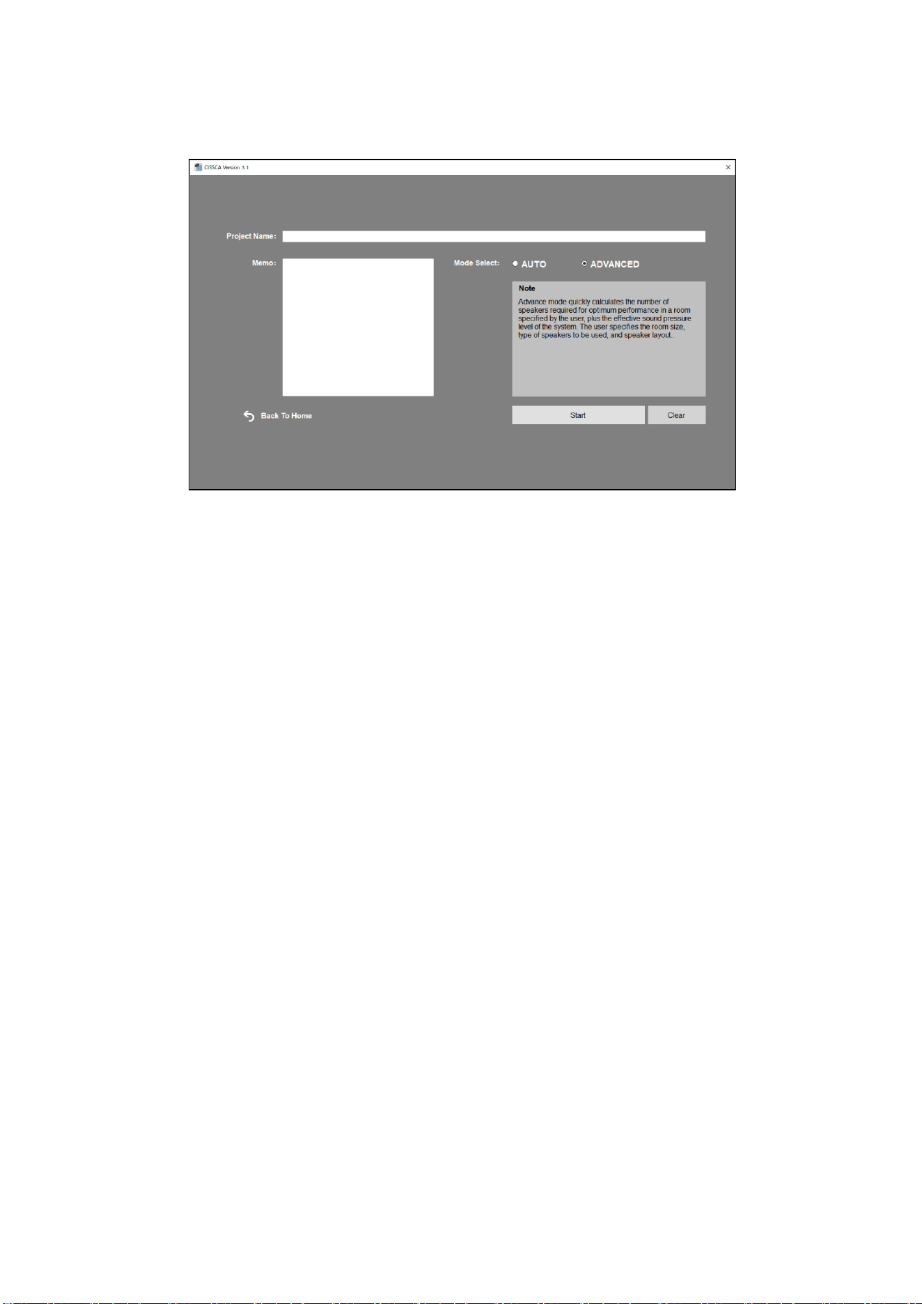
1-2. Creating a Project
Select "New" on the initial screen (HOME screen) to open the Project Settings screen.
Project Settings screen
Enter the name, memo, and the configuration method for the new project. Enter the conditions (as
shown below) and then run the simulation.
[AUTO configuration method]
• 2.1: Enter room conditions
• 2.2: Configure speaker density
• 2.4: Configure the application
• 2.6: View settings
• 2.7: View results
• 2.8: Generate report
[ADVANCED configuration method]
• 2.1: Enter room conditions
• 2.3: Select the speaker
• 2.4: Configure the application
• 2.5: Adjust speaker output
• 2.6: View settings
• 2.7: View results
• 2.8: Generate report
On each condition entry screen, pressing the NEXT button will advance to the next step (screen).
Pressing the BACK button will return to the previous step (screen). You can go back to previous
screens to change the values that have been entered.

9
1-3. Editing a Project
Select "OPEN" on the initial screen (HOME screen) to open the Select Previous Project File screen.
1-4. Common Features
After a project is created, you can save it at any time (SAVE). Other common features are as follows:
• NEW: Creates a new project.
• OPEN: Opens an existing project.
• SAVE: Saves the project.
• SAVE AS: Saves the current project with another name.
• Export CSV: Saves the project content to a CSV (comma-separated text) file.
• OPTIONS: Set various CISSCA options.
• Help: Opens the PDF manual.
• Quit: Closes the application.
10
2. Data Entry
2-1. Entering Room Conditions
Click "OK" on the Project Settings screen to start a new project. If you click "OPEN" on the HOME
screen and select an existing project, the screen that was displayed when the project was saved
appears.
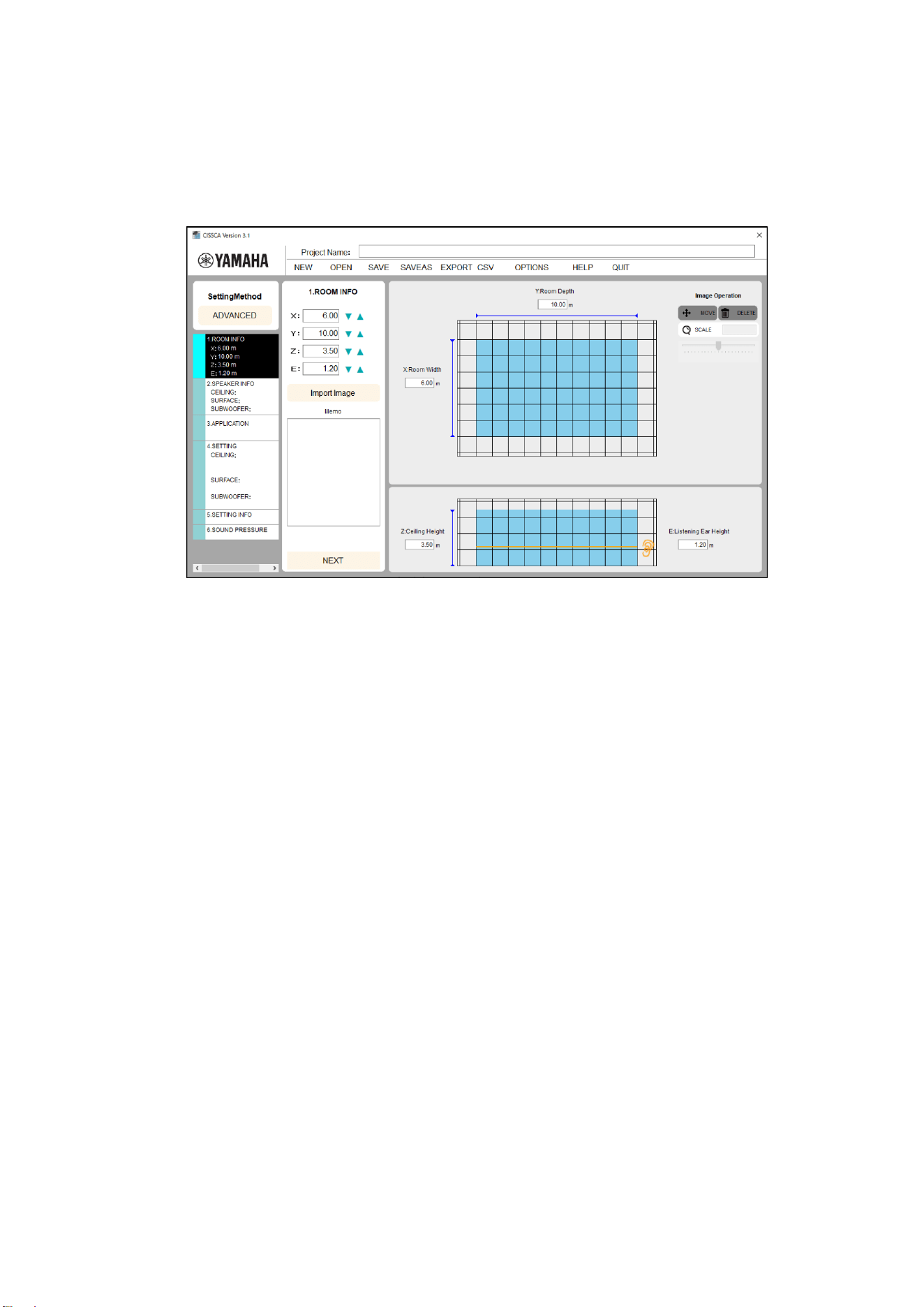
Room information settings
On this screen, enter the environmental information of the target room
・
Project name
Enter a name for managing this design information.
(e.g.) Yamaha Corporation, meeting room, acoustic design
ROOM INFO
• Width (X): Enter the width of the room.
• Depth (Y): Enter the depth of the room.
• Ceiling Height (Z): Enter the height of the room.
• Listening Ear Height: Enter the measurement height. In most cases, this will be the height
of the listener's ears.
• Image: The room plan or another image can be imported into the diagram on the right side
of the screen. Imported images may be moved or resized.
MEMO
Enter a memo. The memo is also printed in reports. Enter information about the room or any
other relevant information.
When you enter these values, they are reflected in the diagram on the right side of the screen so you
can get a general idea of the room dimensions.
Note: Values are entered here in meters. You can also switch to inches. This can be changed
in the Options screen.
Note: Please use a period as a decimal point when entering numbers. Commas will be ignored.
11
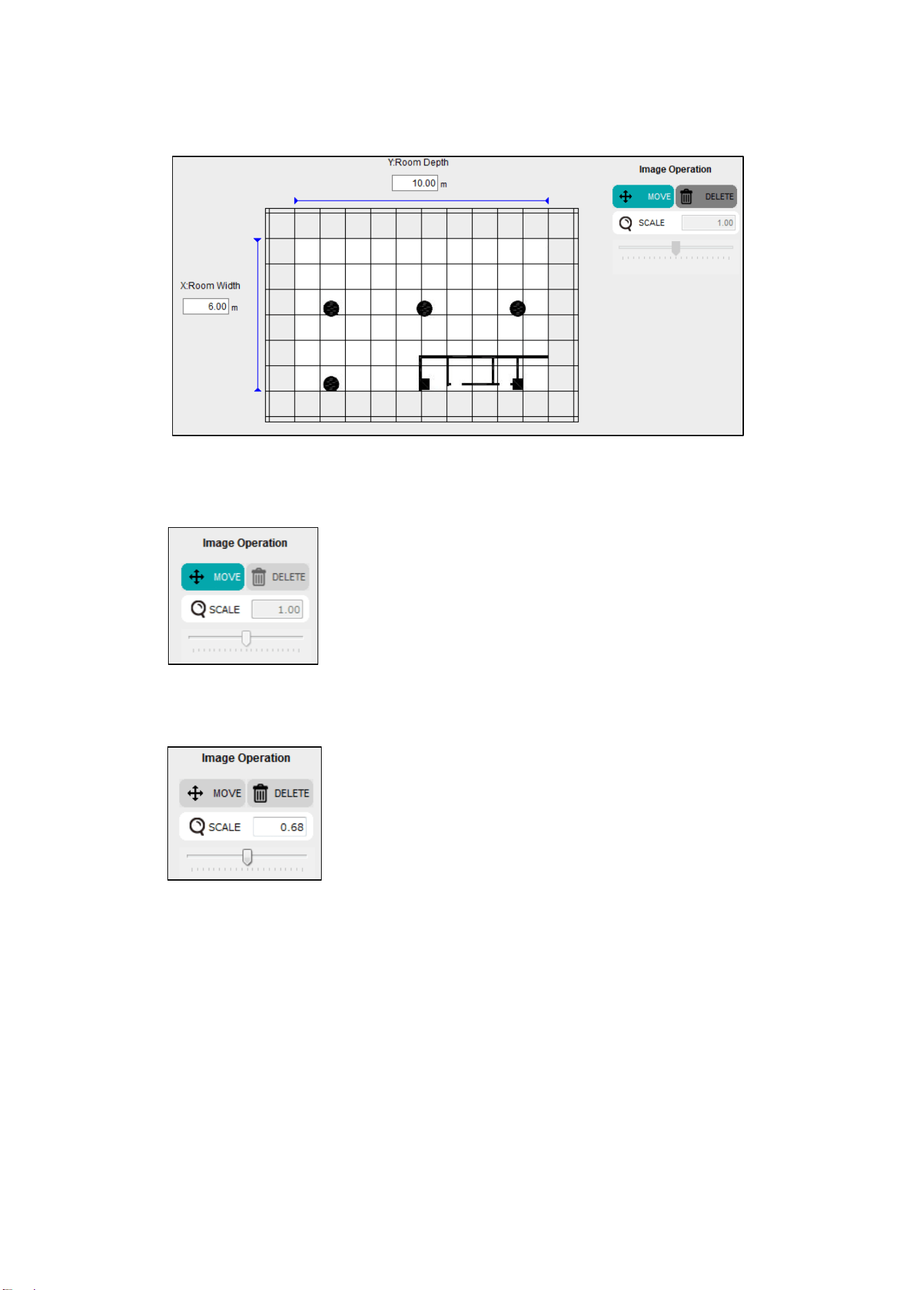
You can also import blueprints or another image to more easily visualize the room.
Imported images may be moved or resized as follows.
Image operations
・ Move: Press the Move button to use the mouse to move an imported image.
The button will appear as shown in the figure to the left when the
image can be moved.
・ Scale: The image can be resized by entering a scale value or by dragging the scale slider.
A scale value of 1 represents the original size of the image.
It can be set to a value of 0.01 or greater.
Moving the slider to the left shrinks the image.
Moving it to the right expands it.
An image may be expanded up to twice its size at once.
Once the scale has been set, the slider resets to the center.
To further expand the image, move the slider again.
・ Delete: Deletes the imported image.
After you enter the values, press the NEXT button to move to the next step.
Note: Please use a period as a decimal point when entering numbers. Commas will be ignored.
12
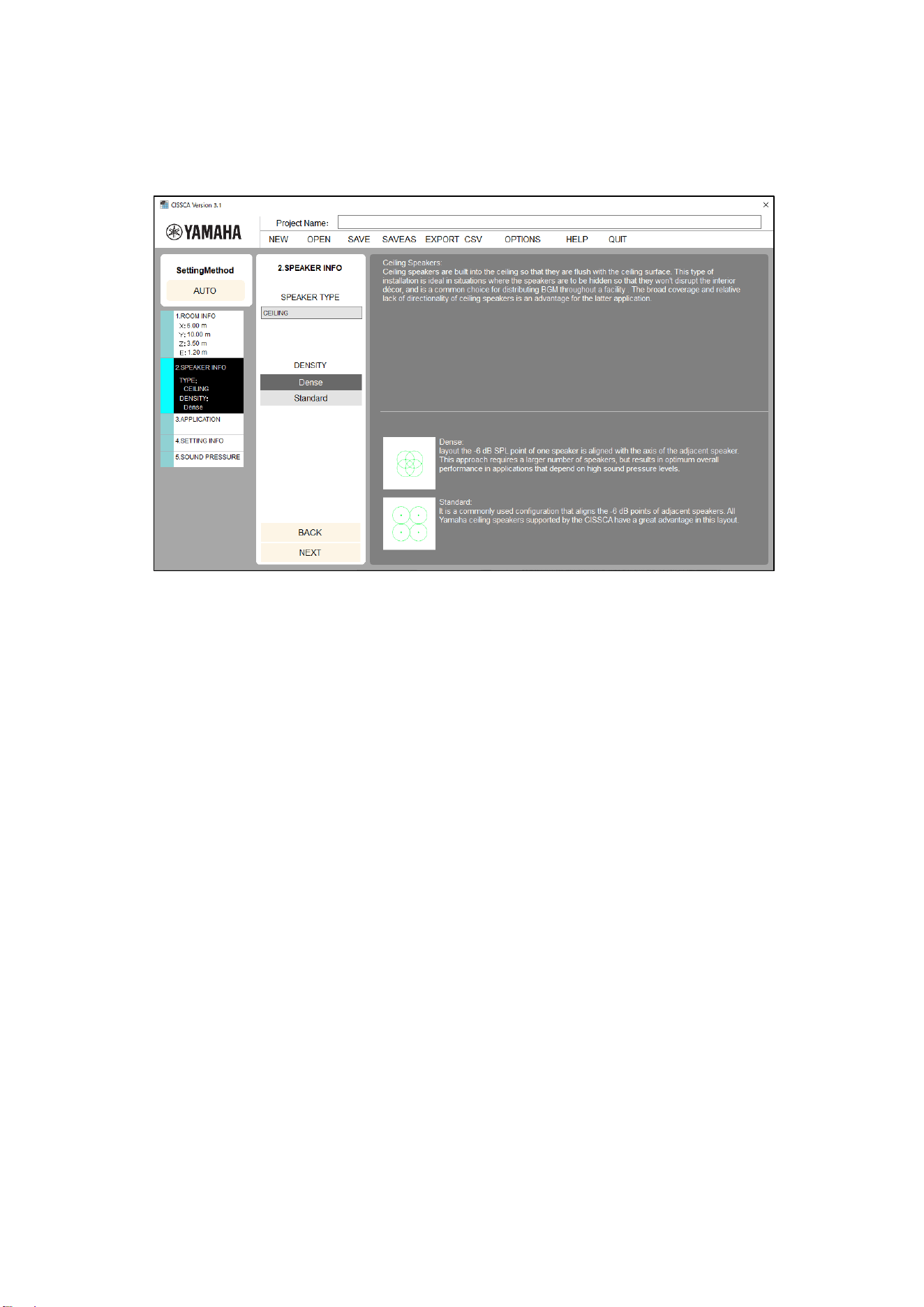
2-2. Configuring Speaker Density
On this screen, configure the speaker density.
Note: AUTO mode only (the speaker type is set to ceiling speaker and cannot be changed).
Speaker density settings
・ Density: Configure the number of speakers (layout density).
* Explanations for each setting are shown in the Settings screen.
After you configure the speaker density, press the NEXT button to move to the next step.
13
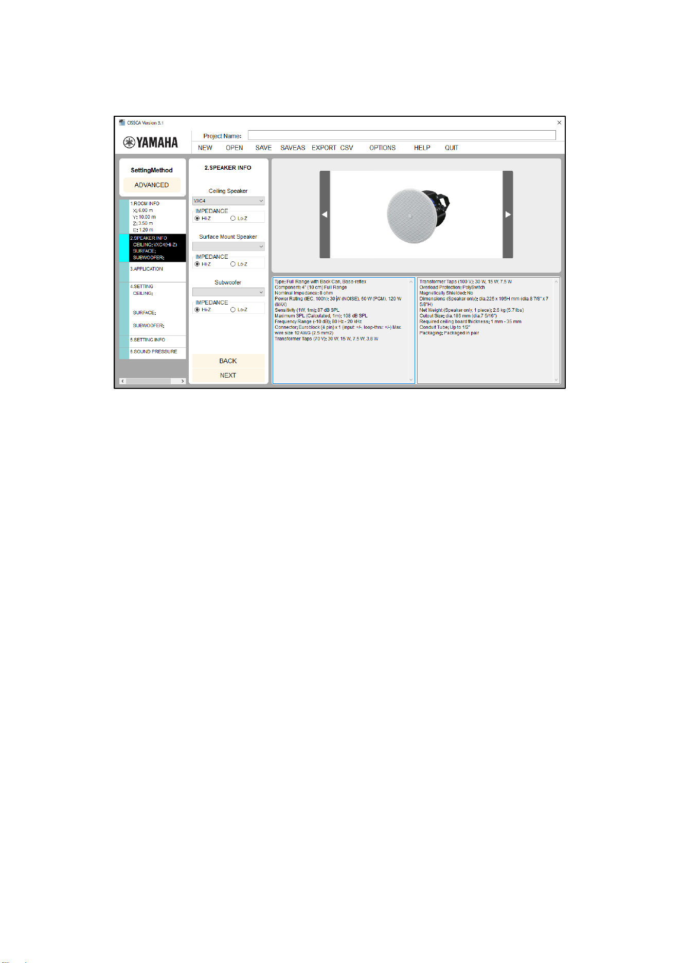
2-3. Selecting the Speaker
On this screen, configure the impedance and the speaker to use.
Note: ADVANCED mode only.
Impedance and speaker settings
・ Impedance: Select the speaker connection method (high-impedance connection or low-
impedance connection).
・ Speaker: Select the speaker to use. When you select a speaker, its photo and usage
information are displayed on the right side of the screen. Some speakers may not be available
to select, depending on the connection method.
After you configure the speaker, press the NEXT button to move to the next step.
14
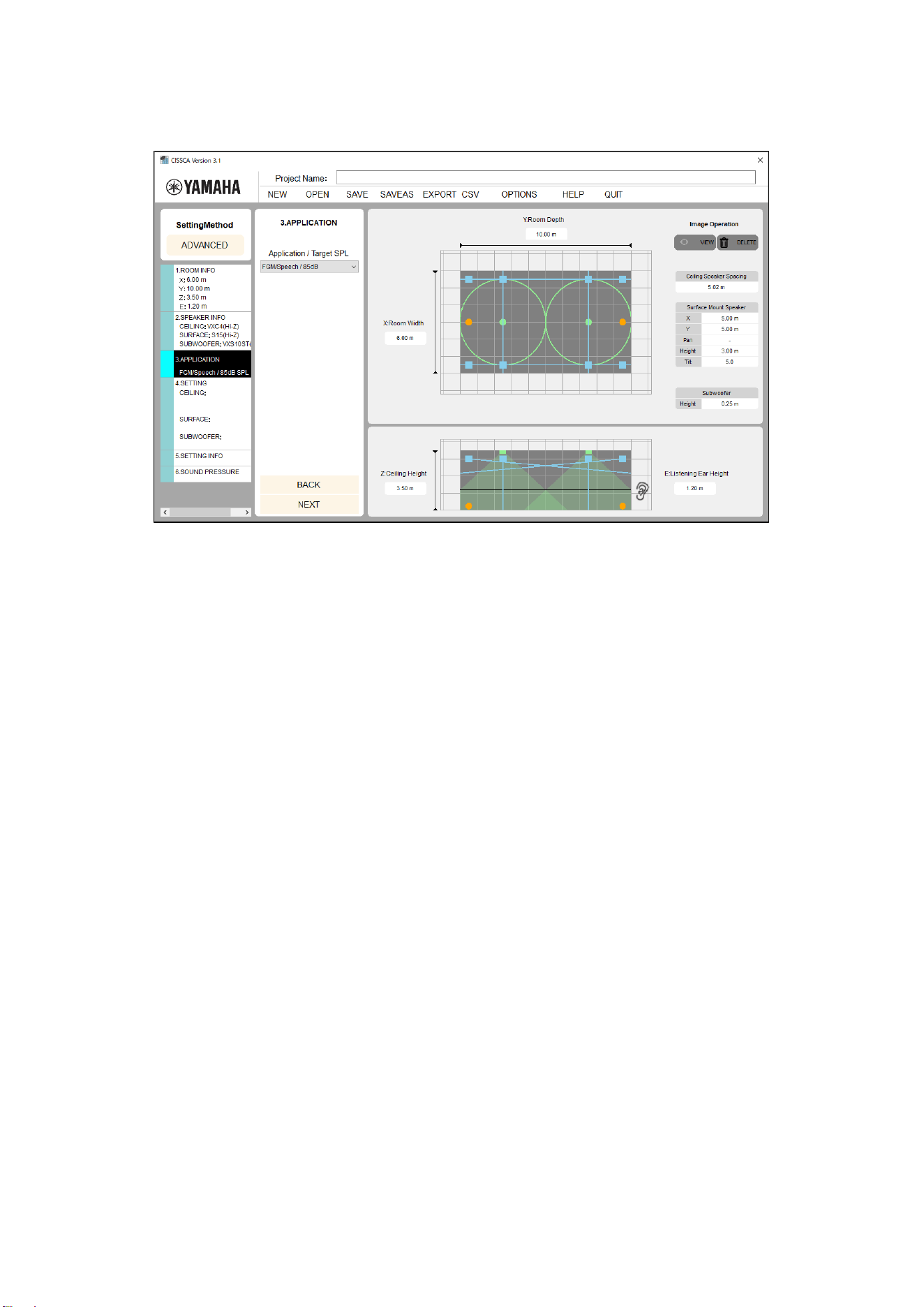
2-4. Configuring the Application
On this screen, set the required sound pressure target (target SPL).
Application settings
(ADVANCED mode is shown here)
・ Application: Consider your application and set the maximum SPL that is necessary at the
sound receiving point.
・ Application/maximum sound pressure: Consider your application and set the maximum SPL
that is necessary at the sound receiving point. Specific examples are provided, so select a
setting that is closest to your target (e.g. High BGM/79 dB). In actuality, there will be some
margin on the maximum SPL depending on the number of speakers that are laid out (layout
density).
Note: The applications that are available to select are different for AUTO mode and ADVANCED
mode.
15
Application examples:
Name
Maximum sound
pressure
Application example
Quiet BGM
70 dB
BGM (quiet)
Low BGM
73 dB
Mid BGM
76 dB
BGM (medium)
High BGM
79 dB
Low FGM/Speech
82 dB
BGM (loud), announcement
FGM/Speech
85 dB
Aggressive BGM
High FGM
88 dB
Low Ent. Music
91 dB
Music for an event (low)
Low Ent. Music
94 dB
Mid Ent. Music
97 dB
Music for an event (medium)
Mid Ent. Music
100 dB
High Ent. Music
103 dB
Music for an event (high)
High Ent. Music
106 dB
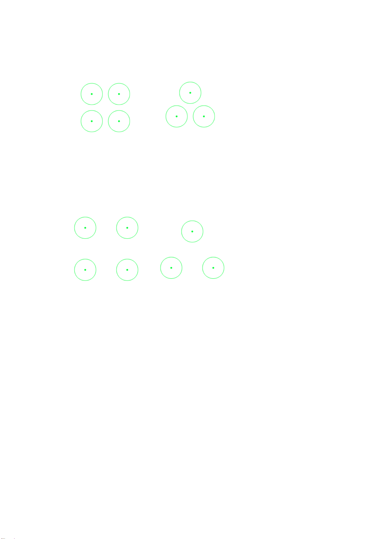
Speakers are automatically arranged in the room based on the room information and speaker density
that were specified in the previous steps. Ceiling speakers are displayed as dots, and the coverage
areas (the area that starts from immediately below the speaker and extends outward horizontally
until the sound pressure decreases by 6 dB) are displayed as circles.
Coverage areas are calculated from the conditions that were entered. They will be slightly different
from the nominal values indicated in catalogs and other related documents.
The spacing between the arranged ceiling speakers is displayed on the right side of the screen.
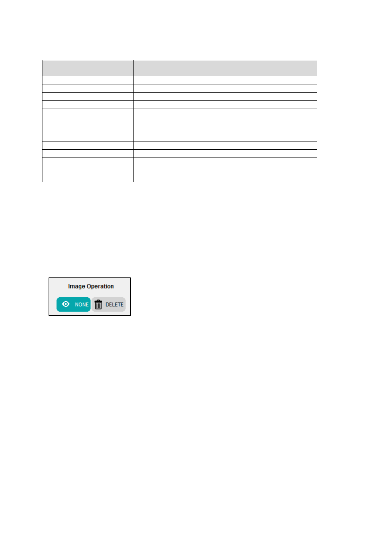
Room images can be shown/hidden or deleted.
・ Show: Press the SHOW/HIDE button to show or hide the imported
image.
・ Delete: Deletes the imported image.
After you configure the application, press the NEXT button to move to the next step.
16
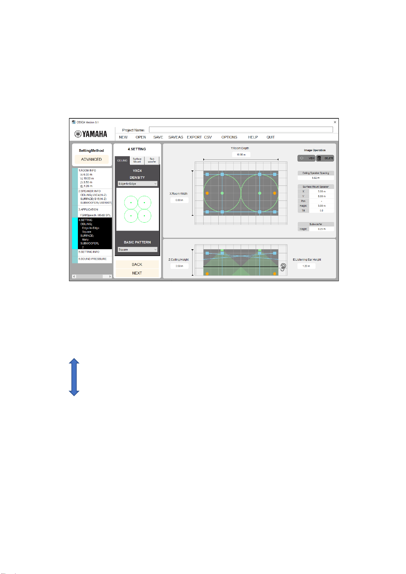
2-5. Adjusting Speaker Output
On this screen, configure the following items.
・ Ceiling speaker density (quantity) and layout type
・ Surface mount speaker quantity, installation spacing, height and angles (tilt and pan)
・ Subwoofer quantity and installation location
Note: ADVANCED mode only.
2-5-1. Ceiling speakers
Adjusting ceiling speaker output
Density (speaker layout density): Adjust the amount of overlap of the coverage areas, which indicates
the boundaries where the sound pressure is 6 dB lower than at the sound receiving point immediately
below the speaker (on the axis). By default, this is set to Edge-to-Edge.
There are five adjustment levels that you can choose from.
High density
Maximum Overlap
Minimum Overlap
Edge-to-Edge
1.4 x Edge-to-Edge
2.0 x Edge-to-Edge
Low density
When you select a certain density, the software starts calculating and redraws the recalculated
coverage areas.
・ Layout type: By default, speakers are arranged in a square pattern. You can also choose a
hexagonal pattern.
・ Speaker spacing: Shows the spacing between speakers.
Note: Speaker spacing is displayed even if only one speaker has been configured.
Consider this to be an indicator of what the spacing would be if there were a second
speaker.
If the number of speakers could exceed 128, an error message will be displayed.
If this happens, select a layout pattern with a lower density.
17
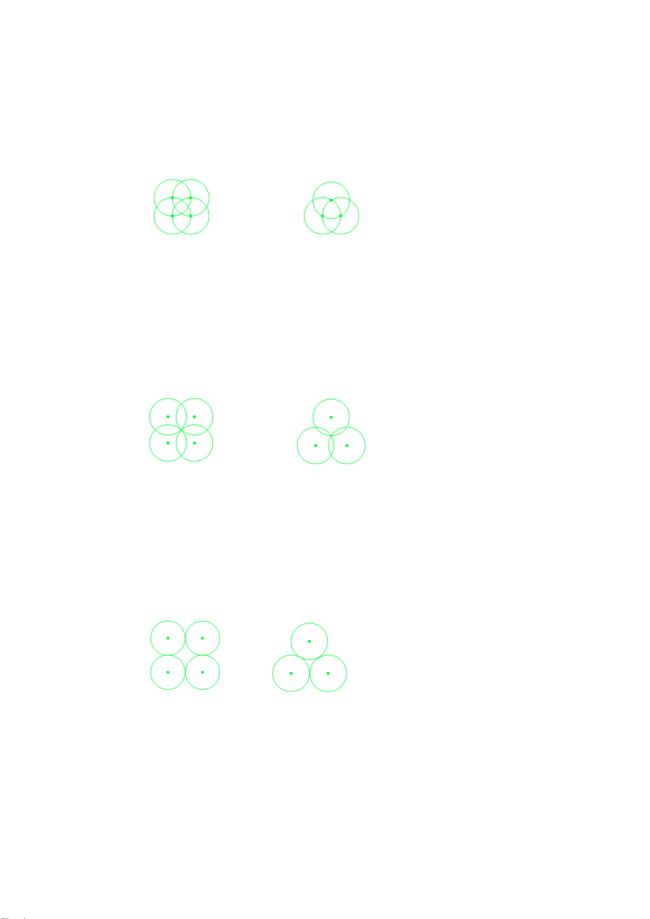
・ Speaker layout patterns
・ Maximum Overlap
In this approach, the -6 dB SPL point of one speaker is aligned with the axis of the adjacent
speakers. This approach requires a larger number of speakers, and is therefore suited for
applications requiring a high sound pressure.
Square Hexagonal
・ Minimum Overlap
Edge-to-edge speaker layouts can result in gaps in the coverage area. Minimum overlap is
used to eliminate these gaps.
Square Hexagonal
・ Edge-to-Edge
This approach aligns the -6 dB SPL points of the coverage areas of adjacent speakers. This
is one of the most standard layouts recommended by Yamaha. It can maximize the
performance of Yamaha speakers supported by CISSCA.
Square Hexagonal
18
・ 1.4 x Edge-to-Edge
In this approach, speakers are spaced 1.4 times further apart than in Edge-to-Edge. As one
of the layouts recommended by Yamaha, this approach reduces the number of required
speakers, resulting in a more economical system than even Edge-to-Edge.
Square Hexagonal
・ 2.0 x Edge-to-Edge
In this approach, speakers are spaced 2 times further apart than in Edge-to-Edge. This is the
most economical approach, but it is not recommended by Yamaha because it can more easily
result in an uneven sound pressure.
Square Hexagonal
19
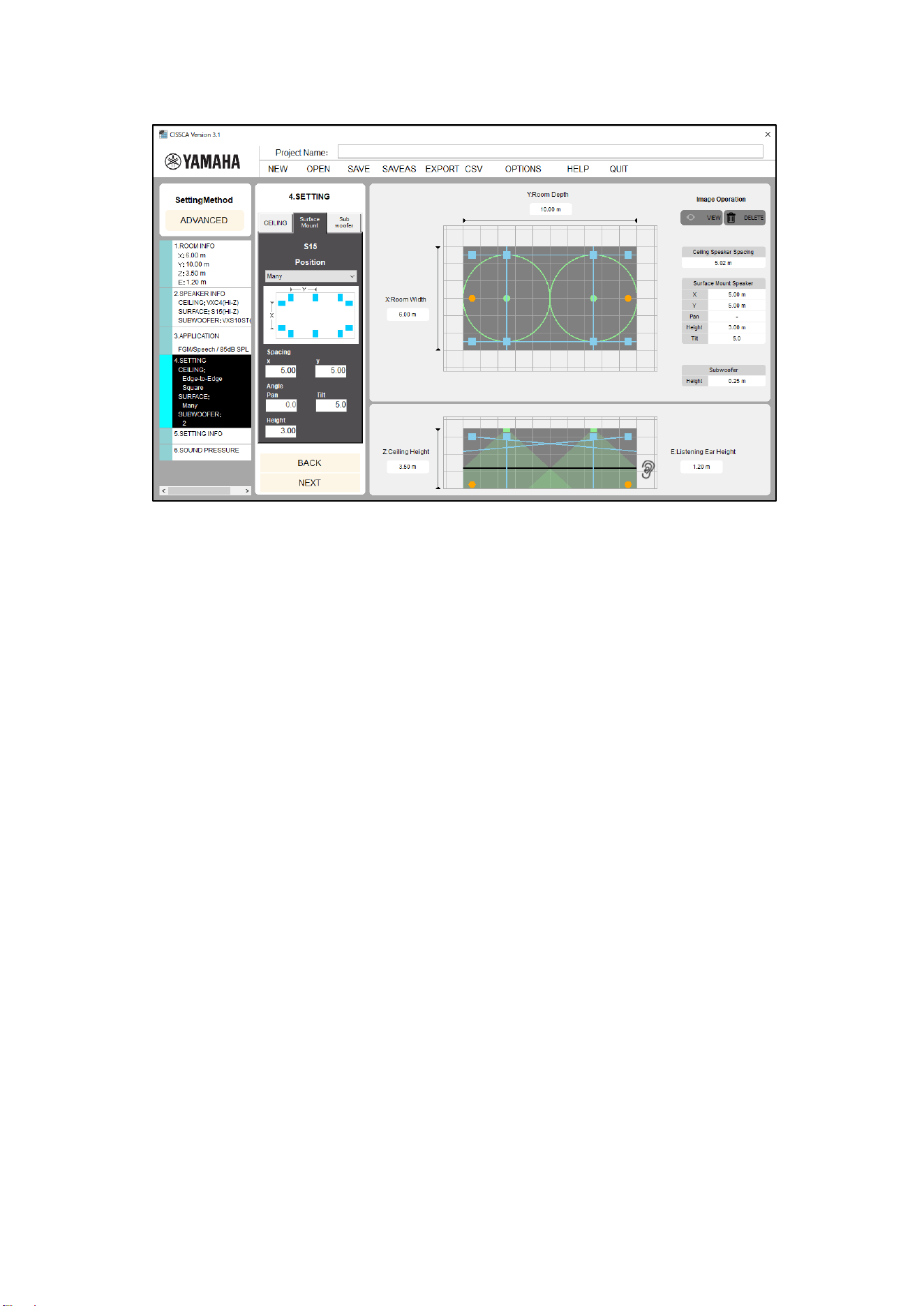
2-5-2. Surface mount speakers
Adjusting surface mount speaker output
Click the Surface Mount Speaker tab to specify settings for arranging surface mount speakers. The
following settings are available.
・ Installation location: Specify the speaker arrangement pattern.
・ None: None.
・ Two: Arranges two speakers in front.
・ Four: Arranges two speakers in front and two speakers in back.
・ Many: Arranges speakers around the room at the specified spacing.
・ Spacing:
・ X: Set the speaker spacing for across the room widthwise.
・ Y: Set the speaker spacing for along the room lengthwise.
This is not available when the layout pattern is set to "Two".
・ Angle:
・ Pan: Set the speaker horizontal angle (pan).
・ Tilt: Set the speaker vertical angle (tilt).
・ Height: Set the speaker installation height.
Note: Please use a period as a decimal point when entering numbers. Commas will be ignored.
20
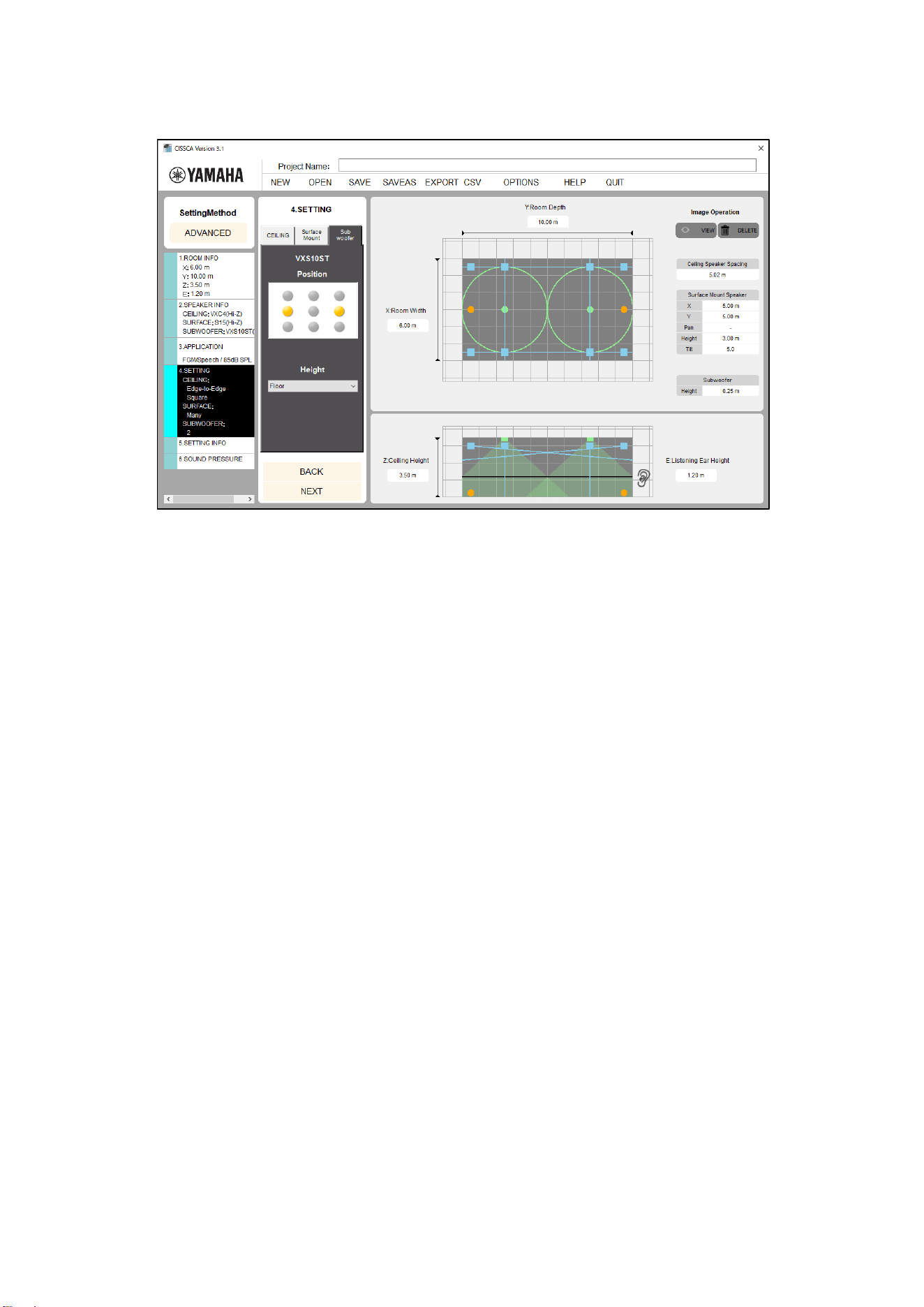
2-5-3. Subwoofers
Adjusting subwoofer output
Click the Subwoofer tab to specify settings for arranging subwoofers.
The following settings are available.
・ Installation location: Select the installation location from the nine available choices (corners
or near the center of the room).
You can install up to nine subwoofers.
・ Height: Set the height of the installation location. Select "Ceiling" or "Floor".
Some subwoofers may not be selected for "Floor" installation.
After you configure the output, press the NEXT button to move to the next step.
21
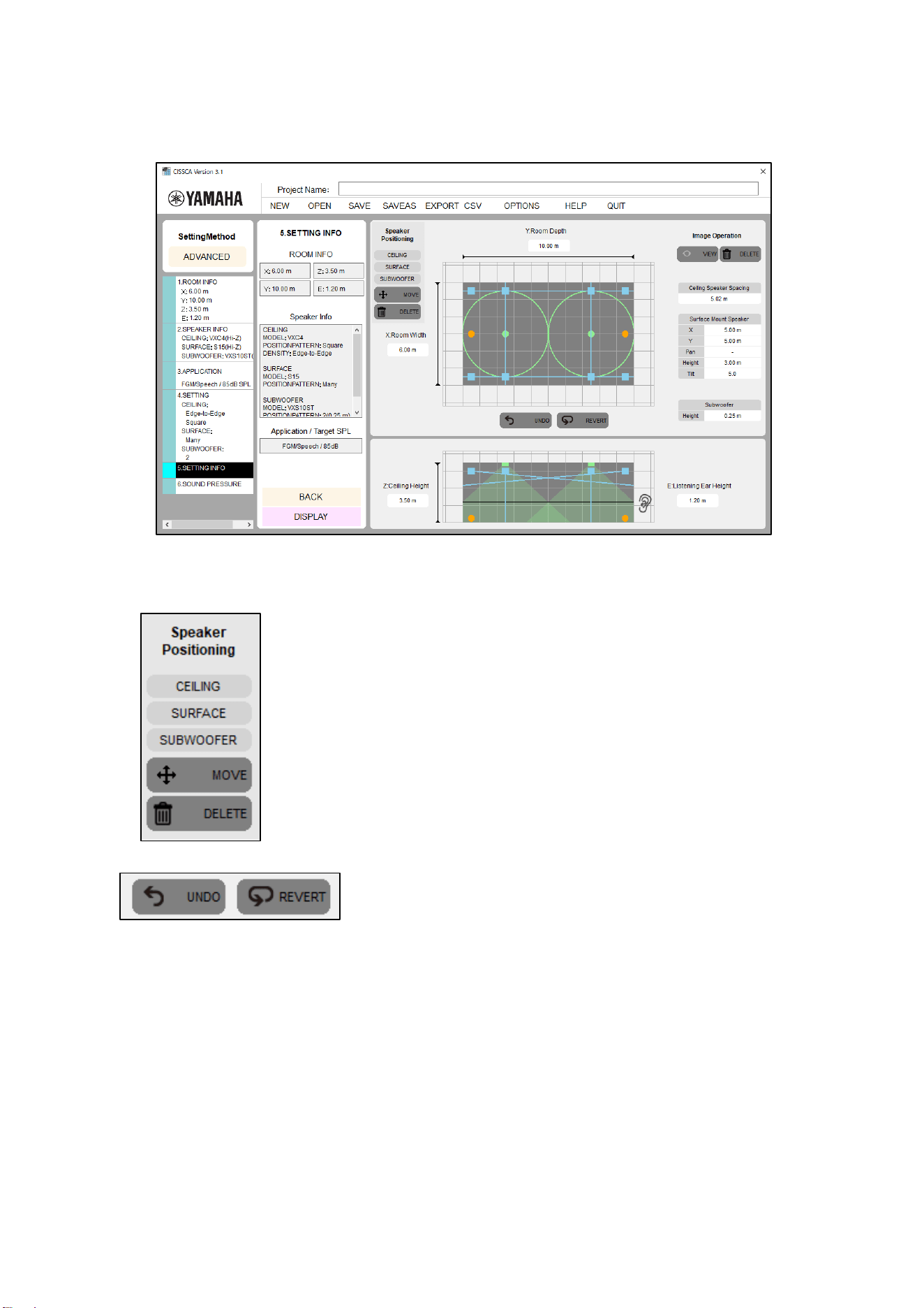
2-6. Viewing Settings
This screen shows information on the speakers that were automatically arranged based upon the
room information, speaker density, and application that were specified in the previous steps.
View settings
Speakers that were automatically arranged can be moved and deleted.
・ Speakers: Selects the speaker to manipulate.
・ Move or delete: Selects how to manipulate the speaker.
・ [Move]
Use the mouse to move the applicable speaker (dot).
・ [Delete]
Use the mouse to click the applicable speaker (dot).
You can also "UNDO" a moved/deleted speaker, or "REVERT" the layout.
・ UNDO: Undo the previous operation.
・ REVERT: Return the speaker arrangement to the initial state.
After confirming and adjusting the settings, press the View Sound Pressure Calculation Results button
to move to the next step.
22
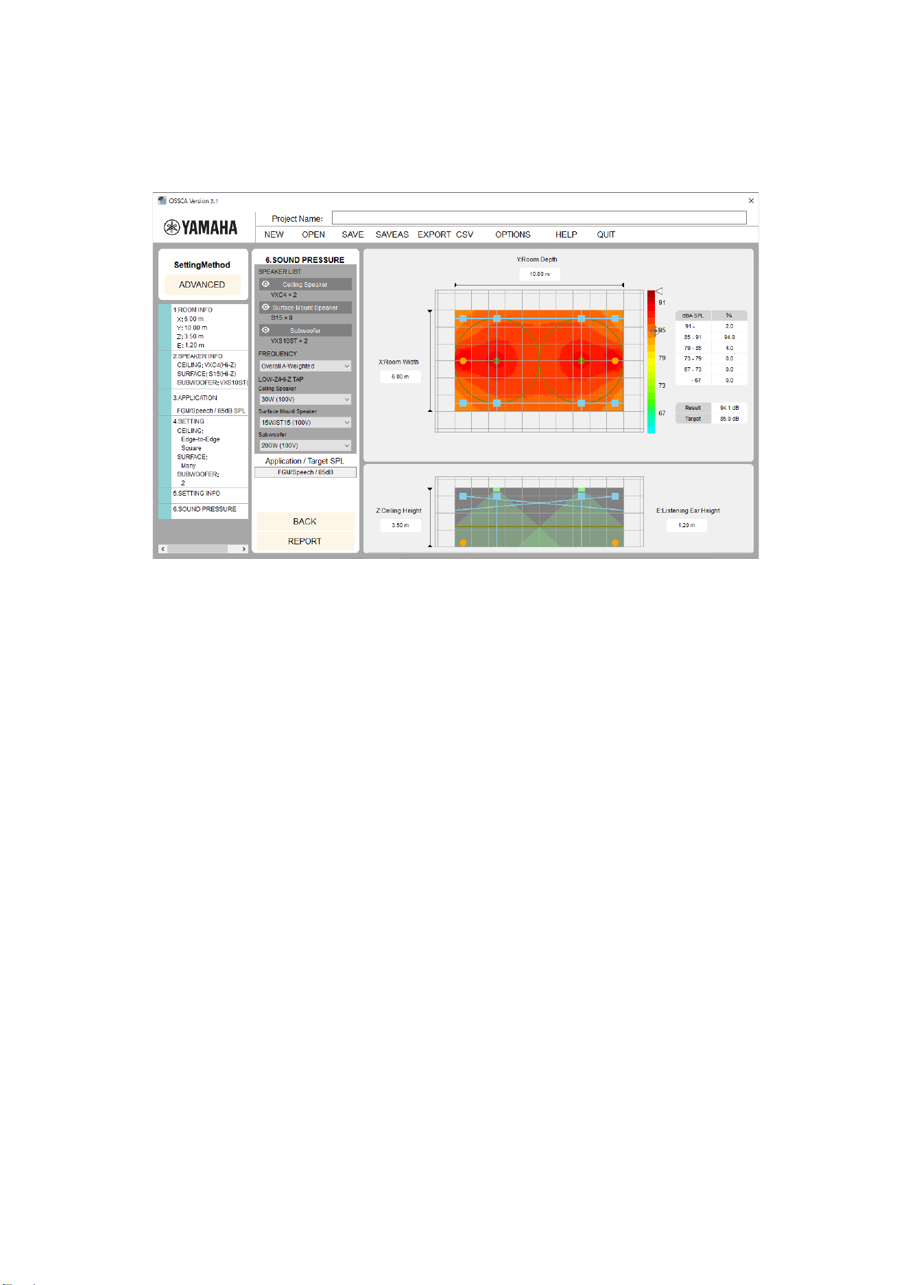
2-7. Viewing Results
On this screen, you can view a sound pressure distribution map created based upon the specified
conditions.
You can update the map by changing measurement conditions such as the speaker output settings
and the measurement frequency.
View results
The sound pressure (intensity) is represented using different colors on the color bar shown on the
right of the map. You can see that it is highest near the speaker, and decreases as you move away
from it. This is the sound pressure when the wattage selected in the currently selected speaker
output settings (Lo-Z/Hi-Z Tap) is output.
The color bar indicates how the colors are mapped to sound pressure. The target mark shown on
the right side of the bar indicates the target sound pressure set in the application. The arrow
indicates the maximum sound pressure in the current speaker output settings. These are also
shown numerically next to Result (calculated result) and Target (target sound pressure) on the right
side of the screen.
The measurement frequency is usually based on the Overall+A weighted (overall bandwidth with A
characteristic curve correction) setting, but you can also change this. If you select a different
frequency, the Result and Target numeric displays will not be shown.
If SPL on/off (sound pressure map display option) is set to ON, the sound pressure colors and
values that are used in the map are indicated on the right side of the screen. The specified target
sound pressure is also indicated.
The table on the right side of the screen (dBA SPL or dB SPL) indicates the sound pressure
distribution ratios in the room at 6 dB intervals.
・ Speaker List: A list of speakers used in the calculation.
You can temporarily exclude speakers from the sound pressure calculation by clicking the
eye icon shown on the left of each speaker name. This is also reflected in reports.
・ Frequency: The frequency band used for the sound pressure calculation can be selected.
The default setting is overall bandwidth with A curve weighting (Overall A-Weighted). Other
available settings are overall bandwidth (Overall Flat), Low (125-500 Hz), Mid (500 Hz-2
kHz), and High (2 kHz-8 kHz). If you change a parameter, the software recalculates and
redraws the map.
・ Lo-Z/HI-Z Tap: Selects the tap.
The software recalculates the sound pressure distribution based upon the selected values.

23
・ REPORT: The software generates a PDF report that can be printed on an A4 paper based
upon the completed design information. You can open the PDF file in Adobe Reader
(recommended) or a similar application, print it, and provide it as design information.
Note: Overlapping speaker coverage areas creates an acoustic space that allows for great
flexibility. However, at the same time remember that the required number of speakers will
increase. To adjust the number of speakers, go back to the speaker density settings and adjust the
speaker density.
Press the REPORT button to move to the next step.
24
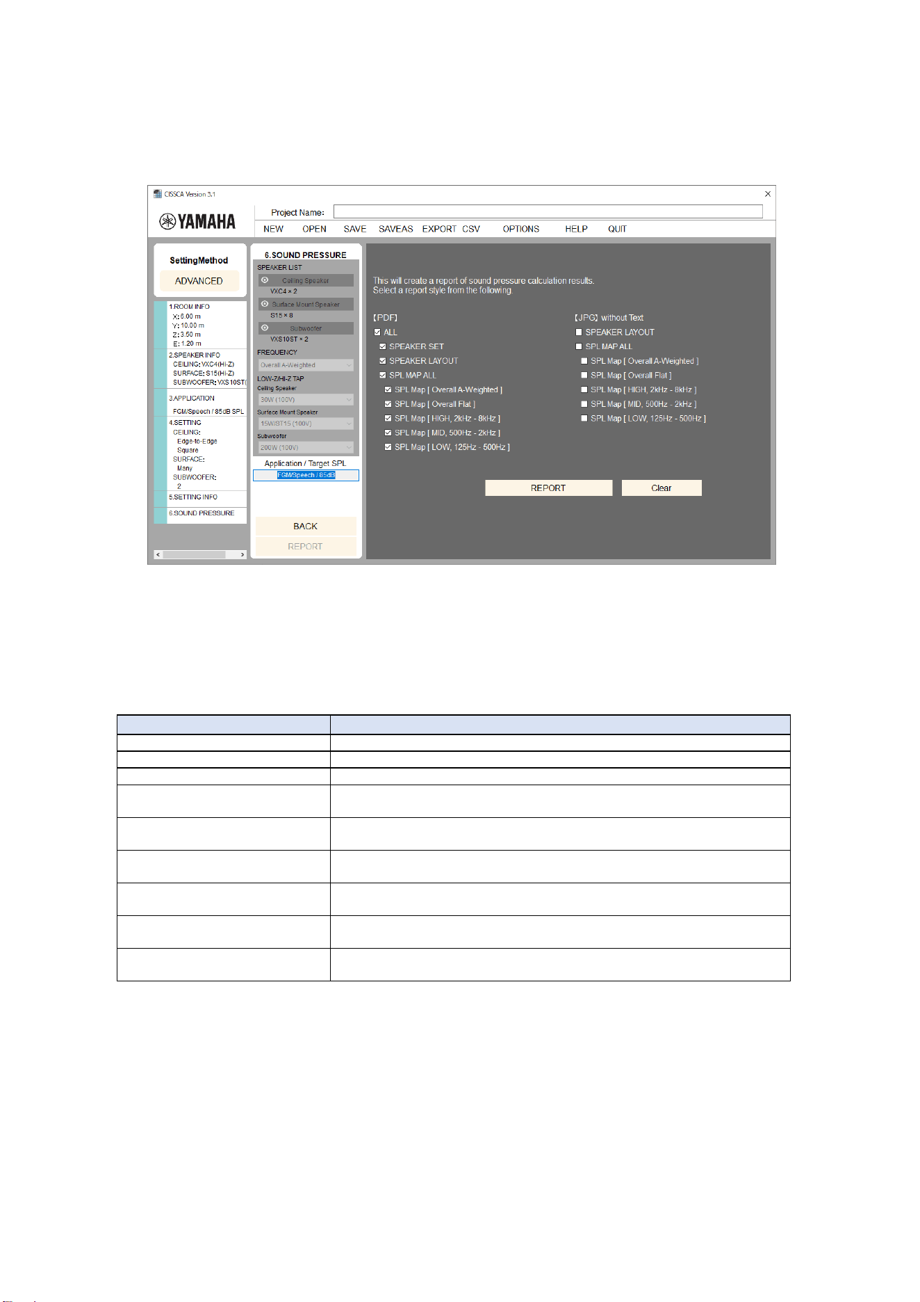
2-8. Generating Reports
Press the REPORT button on the View Results screen to open the Report Output screen (as
shown below).
Generate report
When you press the REPORT button on the right side of the screen, a dialog box will appear
asking you to enter the storage location and file name of the PDF file. Enter the information, and
save the file.
The following items may be specified for PDF output.
Item
Output
[PDF] ALL
Outputs all information to a PDF file.
[PDF] SPEAKERSET
Outputs project information and speaker information to a PDF file.
[PDF] SPEAKERLAYOUT
Outputs project information and the speaker layout to a PDF file.
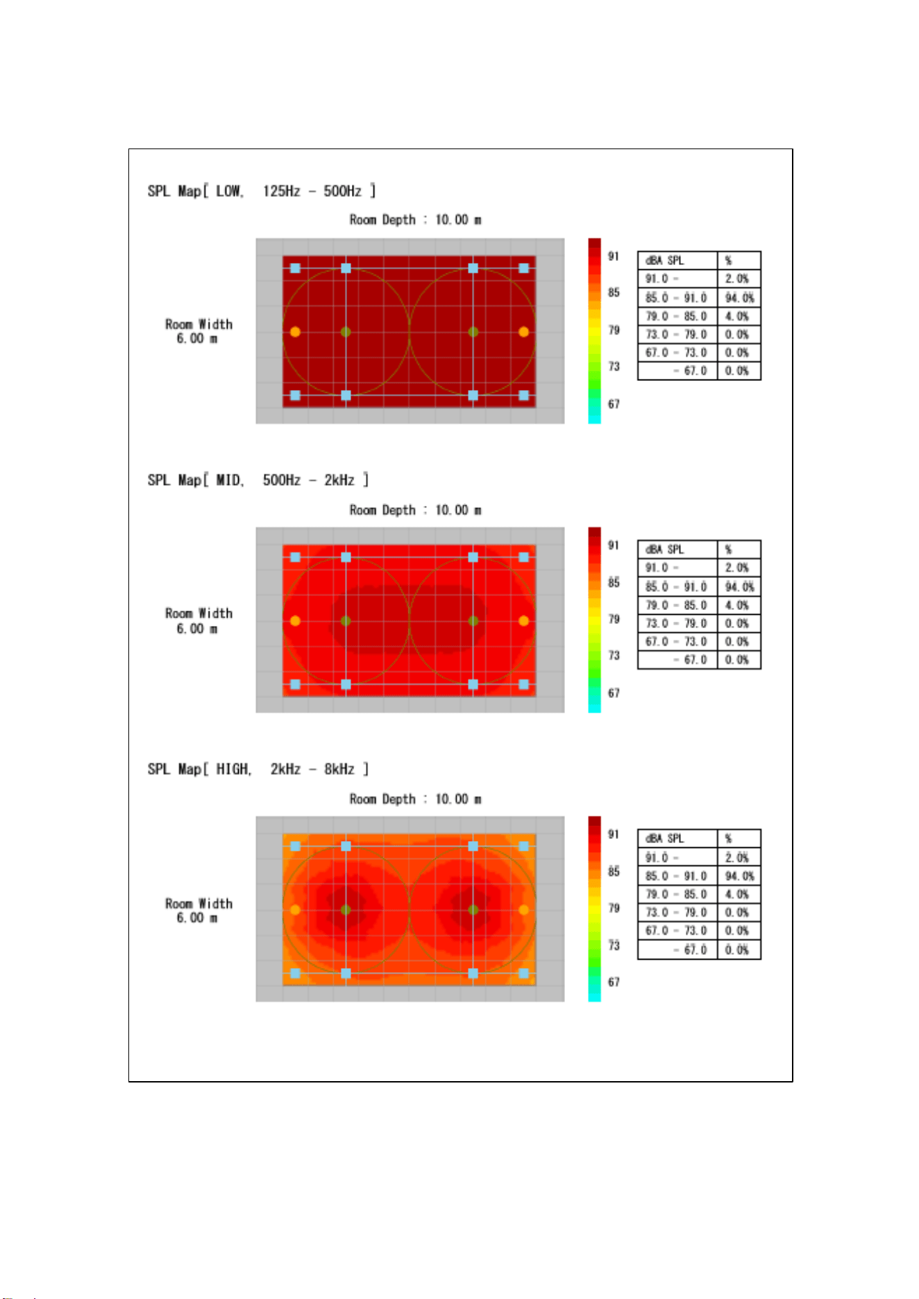
[PDF] SPL MAP ALL
Outputs project information and the sound pressure map for the entire
frequency to a PDF file.
[PDF] SPL MAP
[Overall A-Weighted]
Outputs project information and the sound pressure map of the
measurement frequency [Overall A-Weighted] to a PDF file.
[PDF] SPL MAP
[Overall Flat]
Outputs project information and the sound pressure map of the
measurement frequency [Overall Flat] to a PDF file.
[PDF] SPL MAP
[HIGH, 2 kHz-8 kHz]
Outputs project information and the sound pressure map of the
measurement frequency [HIGH, 2 kHz-8 kHz] to a PDF file.
[PDF] SPL MAP
[MID, 500 Hz-2 kHz]
Outputs project information and the sound pressure map of the
measurement frequency [MID, 500 Hz-2 kHz] to a PDF file.
[PDF] SPL MAP
[LOW, 125 Hz-500 Hz]
Outputs project information and the sound pressure map of the
measurement frequency [LOW, 125 Hz-500 Hz] to a PDF file.

25
The following items may be specified for JPG output.
Item
Output
[JPG] SPEAKERLAYOUT
Outputs the speaker layout diagrams from the report (top view, side
view) to a JPEG image.
[JPG] SPL MAP ALL
Outputs all sound pressure map diagrams to a JPEG image.
[JPG] SPL MAP
[Overall A-Weighted]
Outputs the sound pressure map of the measurement frequency
[Overall A-Weighted] to a JPEG image.
[JPG] SPL MAP
[Overall Flat]
Outputs the sound pressure map of the measurement frequency
[Overall Flat] to a JPEG image.
[JPG] SPL MAP
[HIGH, 2 kHz-8 kHz]
Outputs the sound pressure map of the measurement frequency [HIGH,
2 kHz-8 kHz] to a JPEG image.
[JPG] SPL MAP
[MID, 500 Hz-2 kHz]
Outputs the sound pressure map of the measurement frequency [MID,
500 Hz-2 kHz] to a JPEG image.
[JPG] SPL MAP
[LOW, 125 Hz-500 Hz]
Outputs the sound pressure map of the measurement frequency [LOW,
125 Hz-500 Hz] to a JPEG image.
Note: If SPL on/off (sound pressure map display option) is set to OFF, the SPL MAP cannot
be specified for output. If this is required, set SPL on/off (sound pressure map display option)
to ON.
Note: An image of the room is displayed in the "SPEAKER LAYOUT" section of output reports.
If this is not required, set the image to "hidden" using the image adjustment settings, and
then output the report.
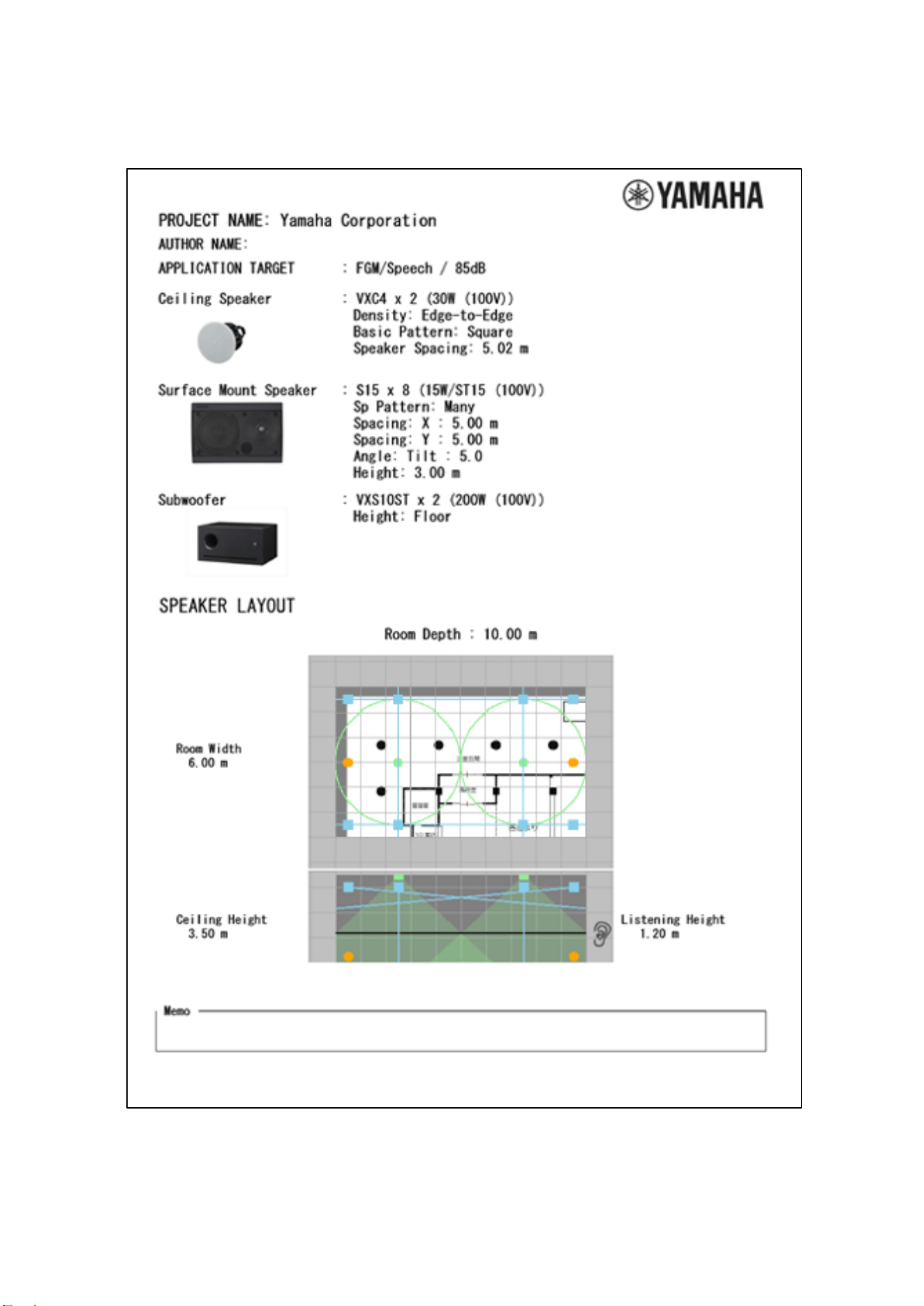
26
Report example (page 1)
27
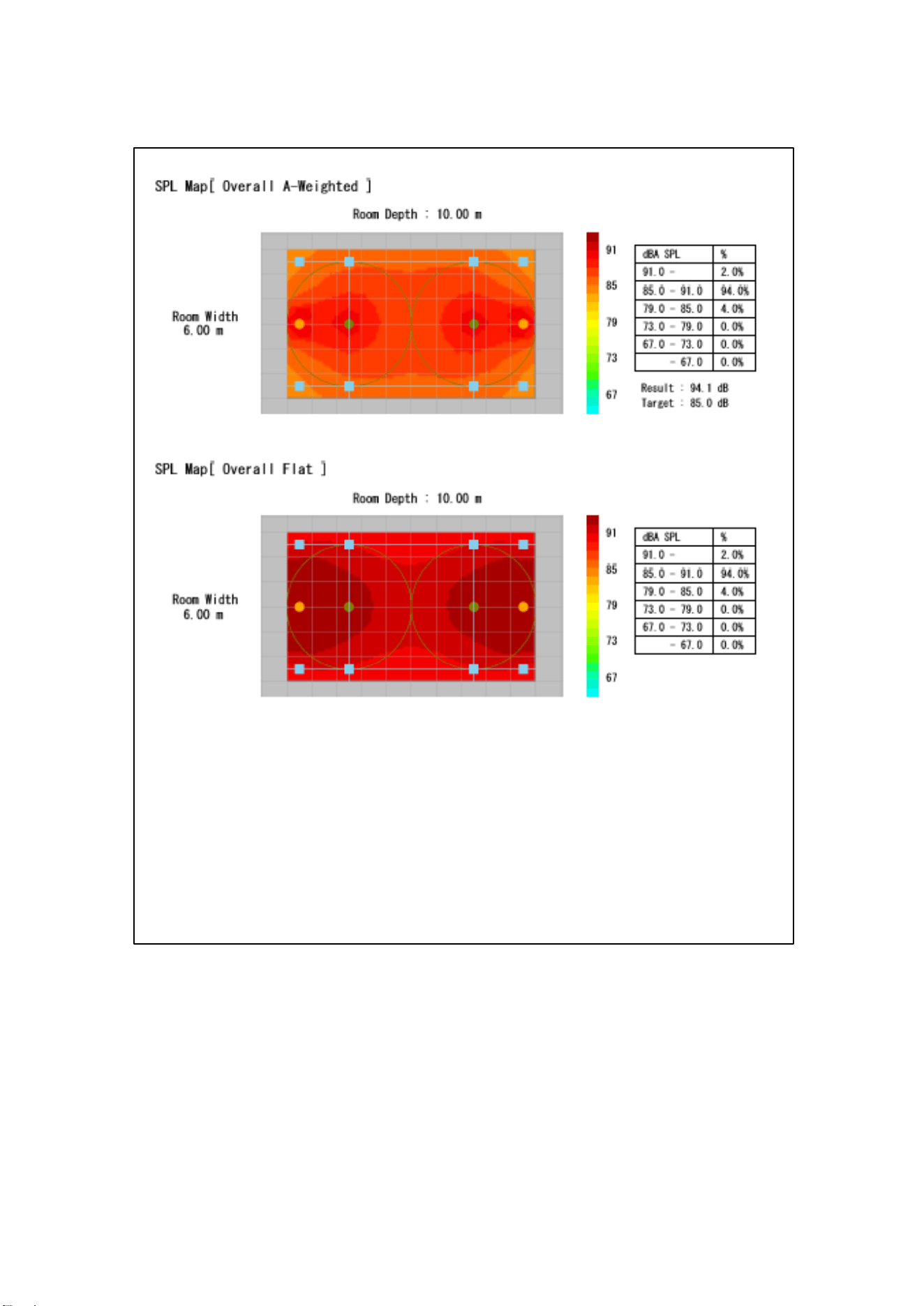
Report example (page 2)
28
Report example (page 3)