USER MANUAL
VERSION A4
April 15, 2025
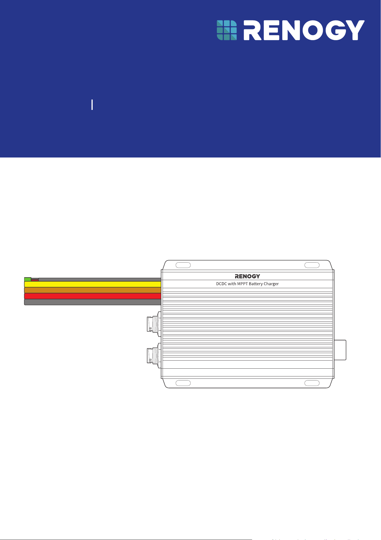
Dual Input DC-DC On-Board with MPPT Battery Charger
RENOGY
RBC2125DS-21W-G2
12V/24V 50A IP67
Before Getting Started
The user manual provides important operation and maintenance instructions for Renogy 12V/24V 50A
IP67 Dual Input DC-DC On-Board with MPPT Battery Charger (hereinafter referred to as battery charger).
Read the user manual carefully before operation and save it for future reference. Failure to observe the
instructions or precautions in the user manual can result in electrical shock, serious injury, or death, or
can damage the battery charger, potentially rendering it inoperable.
z
Renogy ensures the accuracy, sufficiency, and the applicability of information in the user manual
at the time of printing due to continual product improvements that may occur.
z
Renogy assumes no responsibility or liability for personal and property losses, whether directly and
indirectly, caused by the user’s failure to install and use the product in compliance with the user
manual.
z
Renogy is not responsible or liable for failures, damages, or injuries resulting from repair attempted
by unqualified personnel, improper installation, and unsuitable operation.
z
The illustrations in the user manual are for demonstration purposes only. Details may appear
slightly different depending on product revision and market region.
z
Renogy reserves the right to change the information in the user manual without notice. For the
latest user manual, visit renogy.com.
Disclaimer
Renogy 12V/24V 50A IP67 Dual Input DC-DC On-Board with MPPT Battery Charger User Manual © 2025
Renogy. All rights reserved.
RENOGY
and
are registered trademarks of Renogy.
z
All information in the user manual is subject to copyright and other intellectual property rights of
Renogy and its licensors. The user manual may not be modified, reproduced, or copied, in whole or
in part, without the prior written permissions of Renogy and its licensors.
z
The registered trademarks in the user manual are the property of Renogy. The unauthorized use of
the trademarks is strictly prohibited.
Online Manual
Quick Guide User Manual
Renogy App
Renogy App
Download on the

1. General Information ........................................................................................................................... 1
1.1. Symbols Used .............................................................................................................................................. 1
1.2. Introduction .................................................................................................................................................1
1.3. Key Features ................................................................................................................................................1
1.4. SKU ................................................................................................................................................................. 1
2. Get to Know 12V/24V 50A DC-DC Battery Charger with MPPT .....................................................2
2.1. What’s In the Box? ...................................................................................................................................... 2
2.2. Product Overview ....................................................................................................................................... 2
2.3. System Setup ............................................................................................................................................. 3
3. Preparation .........................................................................................................................................4
3.1. Recommended Tools & Accessories ...................................................................................................... 4
3.2. Size Wires ..................................................................................................................................................... 5
3.3. Plan a Mounting Site ................................................................................................................................. 5
3.4. Check the Battery Charger ...................................................................................................................... 6
3.5. Check the Auxiliary Battery ......................................................................................................................7
3.6. Check the Solar Panel(s) ........................................................................................................................... 8
3.7. Check the Alternator on Your Automobile ...........................................................................................10
3.8. How to Install 15/32 in Lugs or 3/8 in Lugs? ....................................................................................... 11
3.9. How to Install Cables on the Battery Charger? ...................................................................................12
4. Installation ........................................................................................................................................ 15
4.1. Wear Insulating Gloves ............................................................................................................................. 15
4.2. Connect the Battery Charger to a Busbar ...........................................................................................15
4.3. Connect the Battery Charger to an Auxiliary Battery .......................................................................16
4.4. Connect the Battery Charger to a Solar Panel ....................................................................................17
4.5. Connect the Battery Charger to a Starter Battery .............................................................................18
4.6. Install a Battery Temperature Sensor ...................................................................................................19
4.7. CAN Communication Wiring (Optional) .................................................................................................19
4.8. Wire Inspection ......................................................................................................................................... 23
5. LED Indicators ...................................................................................................................................24
6. Configuration ....................................................................................................................................25
6.1. Set a Battery Type .................................................................................................................................... 25
6.2. User Mode ..................................................................................................................................................25
6.3. Configure Charging Parameters ........................................................................................................... 26
6.4. Activate Lithium Batteries ..................................................................................................................... 27
7. Monitoring .........................................................................................................................................28
7.1. Short-Range Monitoring .........................................................................................................................28
7.2. Wireless Long-Range Monitoring ......................................................................................................... 29
7.3. Wired Long-Range Monitoring (Backbone Network) ........................................................................30
7.4. Wired Long-Range Monitoring (Daisy Chain Network) ......................................................................31
Table of Contents

8. Working & Charging Logic ................................................................................................................32
8.1. Automatic Voltage Matching Function ................................................................................................32
8.2. Charging Logic..........................................................................................................................................33
8.3. Battery Charging Stages ........................................................................................................................ 35
9. Troubleshooting................................................................................................................................37
10. Dimensions & Specifications ...........................................................................................................39
10.1. Dimensions ................................................................................................................................................ 39
10.2. Technical Specifications .........................................................................................................................39
11. Maintenance ..................................................................................................................................... 40
11.1. Inspection ................................................................................................................................................. 40
11.2. Cleaning .....................................................................................................................................................40
11.3. Storage ....................................................................................................................................................... 40
12. Emergency Responses ..................................................................................................................... 41
12.1. Fire ...............................................................................................................................................................41
12.2. Flooding ......................................................................................................................................................41
12.3. Smell ............................................................................................................................................................41
12.4. Noise ............................................................................................................................................................41
Renogy Support ........................................................................................................................................42

— 1 —
1. General Information
1.1. Symbols Used
The following symbols are used throughout the user manual to highlight important information.
WARNING: Indicates a potentially hazardous condition that could result in personal injury or
death.
CAUTION: Indicates a critical procedure for safe and proper installation and operation.
NOTE: Indicates an important step or tip for optimal performance.
1.2. Introduction
Renogy 12V/24V 50A IP67 Dual Input DC-DC On-Board with MPPT Battery Charger allows you to
charge your house (auxiliary) battery from solar panels or the starter battery in your RV. It is a charging
device that not only converts direct current to the appropriate voltage for charging a battery but also
incorporates MPPT (Maximum Power Point Tracking) technology to optimize power conversion from
solar panels.
The battery charger is versatile and can be connected to either 12V or 24V auxiliary batteries. The built-
in buck converter module is designed to adapt to different voltage requirements, enabling 12V solar
panels to charge 24V batteries at their native voltage and 24V solar panels to charge 12V batteries at
their native voltage.
Thanks to the exclusive intelligent charging logic, the battery charger prioritizes solar energy and
automatically adjusts working modes based on sunlight intensity, efficiently charging your house
battery while easing the load on generators
.
The battery charger seamlessly switches to solar
charging in ample sunlight and smoothly transitions to generator charging during low light, ensuring
uninterrupted device power.
Equipped with intelligent boost and buck logic, it seamlessly accommodates 12V/24V voltage systems,
elevating DIY possibilities to the uttermost. Maximizing energy utilization, it boasts a robust 50A current
and an impressive 720W output power, making a slim, waterproof dual charging solution perfect for
confined spaces. You can embrace an eco-conscious charging experience without compromising
efficiency or space, redefining sustainable energy utilization with the battery charger.
1.3. Key Features
z
Intelligent Boost and Buck Logic
Effortlessly converts between 12V and 24V systems with over 90% efficiency for boosting and 94%
for voltage reduction, offering a dual charging solution adaptable to various DIY configurations.
z
Prioritize Solar Green Energy
Features auto-switching charging mode while prioritizing green power, achieving 97% charging
efficiency, and delivering 720W high charging power for a greener approach.
z
IP67 Waterproof
Ensures robust safety standards with multiple certifications like CE, FCC,and RoHS, guaranteeing a
secure off-grid power experience alongside strong IP67 waterproof performance.
z
Extremely Compact and Lightweight
Compact and light enough to be mounted in engine compartment and side storeroom, allowing for a
more spacious and comfortable living space.
z
Smart Living Unleashed
Compatible with both built-in Bluetooth and wired CAN communication to get real-time data, striving
for the most reliable experience for off-grid users.
1.4. SKU
Renogy 12V/24V 50A IP67 Dual Input DC-DC On-Board
with MPPT Battery Charger
RBC2125DS-21W-G2
— 2 —
2. Get to Know 12V/24V 50A DC-DC Battery Charger with MPPT
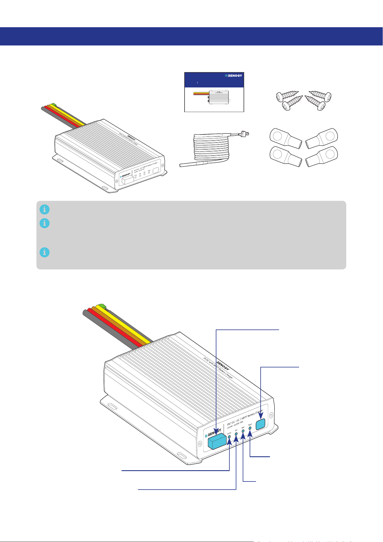
2.1. What’s In the Box?
VERSION A4
April 15, 2025
Dual Input DC-DC On-Board with MPPT Battery Charger
RENOGY
12V/24V 50A IP67
RBC2125DS-21W-G2
QUICK GUIDE
Renogy 12V/24V 50A IP67
Dual Input DC-DC On-Board
with MPPT Battery Charger × 1
Quick Guide × 1
15/32 in Lugs
(M12 Ring Terminals) × 4
Battery Temperature
Sensor (3 m) × 1
Mounting Screws x 4
ST4*20 mm
Make sure that all accessories are complete and free of any signs of damage.
The accessories and product manual listed are crucial for the installation, excluding warranty
information and any additional items. Please note that the package contents may vary depending
on the specific product model.
The 15/32-inch lugs (M12 ring terminals) are used to connect starter battery on your vehicle to
your auxiliary battery.
2.2. Product Overview
█
Right-side View
Battery Type
Setting Button
Battery Type Indicator
Auxiliary Battery Indicator
Alternator Charging Indicator
Solar Charging Indicator
Bluetooth Antenna
— 3 —
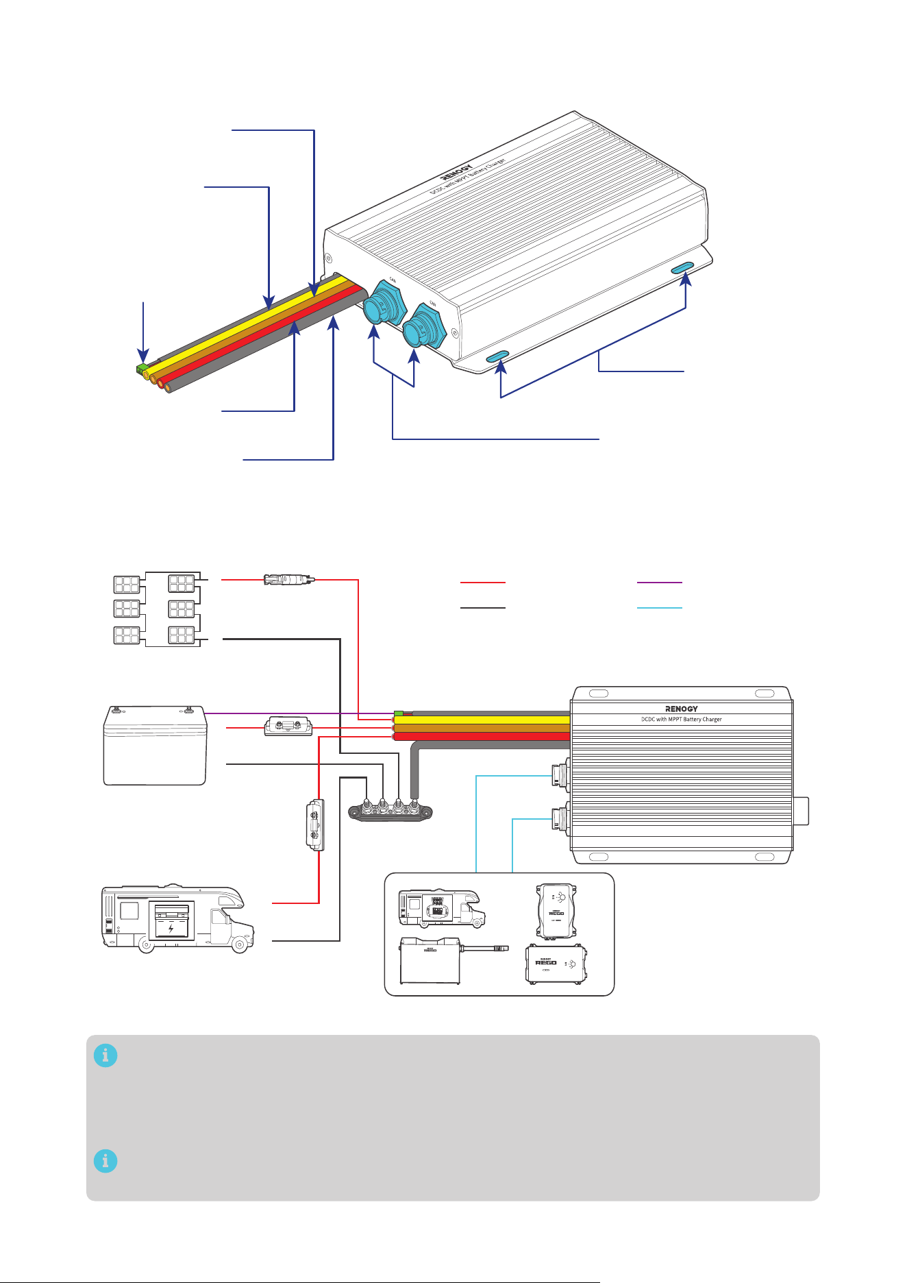
█
Left-side View
Mounting Holes
CAN Communication Ports
Battery Temperature
Sensor Cable
(with connectors)
Positive Starter
Battery Cable (red)
Negative Common
Cable (black)
Positive Solar
Cable (yellow)
Positive Auxiliary
Battery Cable (brown)
2.3. System Setup
RV-C or Renogy devices supporting CAN communication
Solar Panel (s)
Auxiliary Battery
(12V / 24V)
Starter Battery
DC-DC Battery Charger
+
-
+
-
+
-
Communication
Temperature
Negative
Positive
The wiring diagram only shows the key components in a typical DC-coupled off-grid energy
storage system for the illustrative purpose. The wiring might be different depending on the
system configuration. Additional safety devices, including disconnect switches, emergency
stops, and rapid shutdown devices, might be required. Wire the system in accordance with the
regulations at the installation site.
The battery charger can be connected separately to the solar panel for charging the auxiliary
battery or to the vehicle’s starting battery for charging the auxiliary battery.
— 4 —
3. Preparation
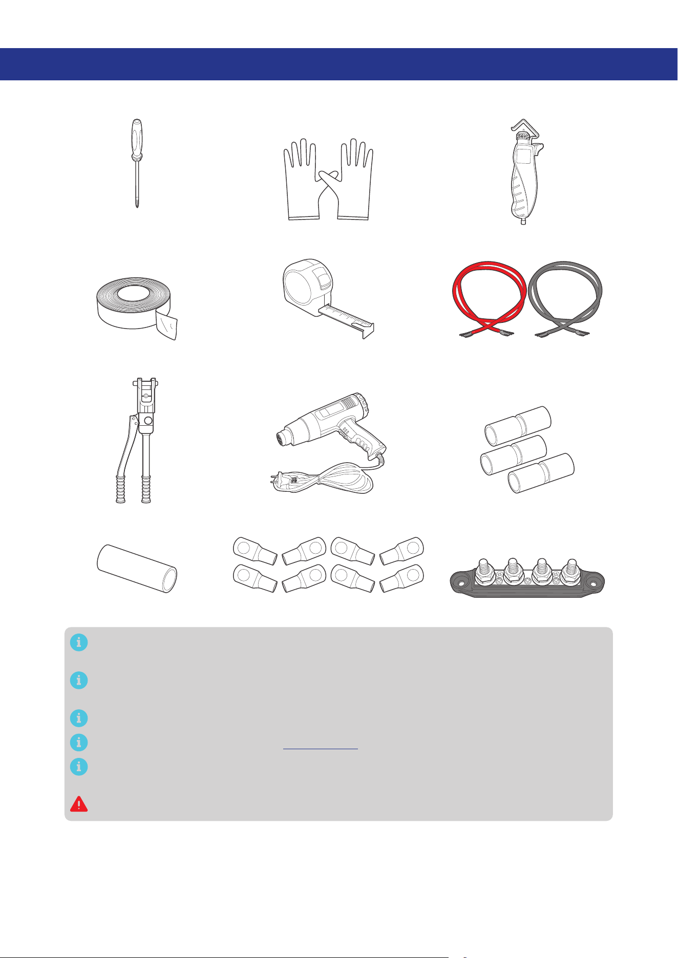
3.1. Recommended Tools & Accessories
Measuring TapeInsulation Tape
3
4
5
6
Insulating Gloves
Phillips
Screwdriver (#1)
Wire stripper
Manual Hydraulic Pliers
Heat Gun
Heat Shrink Tubing
Butt-Splices
3/8 in Lugs (M10 Ring Terminals)
Busbar (60A to 100A)
Bare Wires
Prior to installing and configuring the battery charger, prepare the recommended tools,
components, and accessories.
Choose proper mounting screws specific to your installation site. This manual takes self-tapping
screws for wooden walls as an example.
The 3/8-inch lugs (M10 ring terminals) are used to connect the busbar and ANL fuse.
For how to size bare wires, refer to “3.2. Size Wires” in this manual.
In this manual, the red cable represents the positive cable, and the gray cable represents the
negative cable.
Do not use the bare wire if there is any visible damage.
— 5 —
3.2. Size Wires
Select proper bare wires based on the cable length in your power system. Refer to the table below for
recommended gauge sizes.
Cable Cable Length Cable Gauge Size
Output
(to Auxiliary Battery)
0 ft to 10 ft (0 m to 3 m) 10 AWG (5.25 mm²)
11 ft to 20 ft (3 m to 6 m) 8 AWG (8.36 mm²)
21 ft to 30 ft (6 m to 9 m) 6 AWG (13.3 mm²)
Input
(from Starter Battery)
0 ft to 10 ft (0 m to 3 m) 10 AWG (5.25 mm²)
11 ft to 20 ft (3 m to 6 m) 8 AWG (8.36 mm²)
21 ft to 30 ft (6 m to 9 m) 6 AWG (13.3 mm²)
Input
(from Solar Panel)
0 ft to 10 ft (0 m to 3 m) 12 AWG (3.31 mm²)
11 ft to 20 ft (3 m to 6 m) 10 AWG (5.25 mm²)
21 ft to 30 ft (6 m to 9 m) 10 AWG (5.25 mm²)
The cable specifications listed above account for critical, less than 3% voltage drop and may not
account for all configurations.
The specification of fuse cable is consistent with the input or output terminal of the battery
charger.
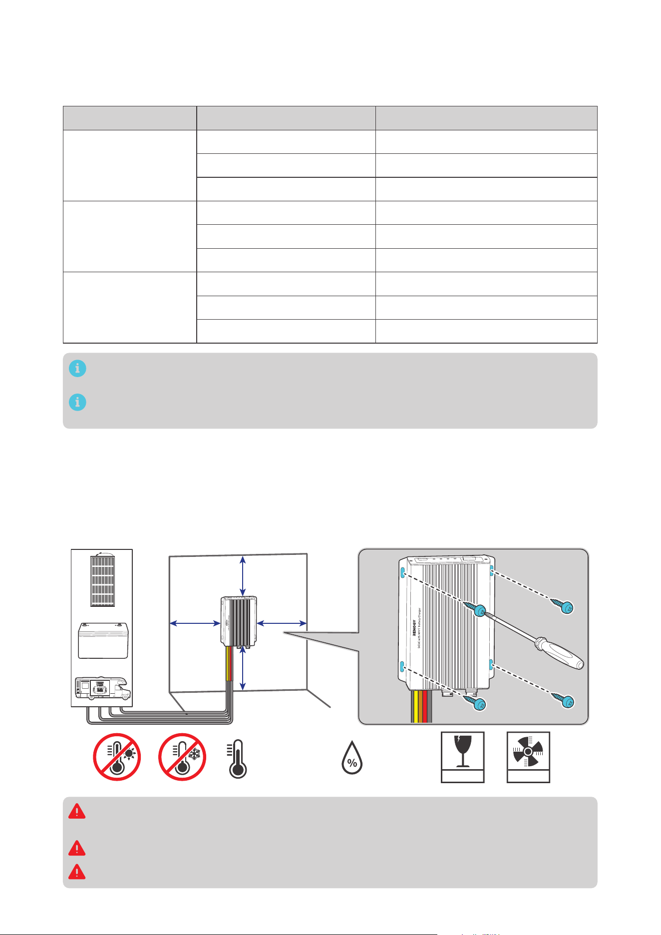
3.3. Plan a Mounting Site
The battery charger requires adequate clearance for installation, wiring and ventilation. The minimum
clearance is provided below. Ventilation is highly recommended if it is mounted in an enclosure. Select
a proper mounting site to ensure the battery charger can be safely connected to the battery, solar
panel(s), and the other necessary devices with the relevant cables.
You can mounting the battery charger vertically on a wall or horizontally on the floor.
5.91 in
(150 mm)
5.91 in
(150 mm)
5.91 in
(150 mm)
FRAGILE
VENTILATION
0% to 95%
-31°F to 212°F
-35°C to 100°C
Solar
Vehicle
Stage
Battery
5.91 in
(150 mm)
Solar
Vehicle
Stage
Battery
Risk of explosion! Never install the battery charger in a sealed enclosure with flooded batteries!
Do not install the battery charger in a confined area where battery gases can accumulate.
The battery charger should be installed on a flat surface protected from direct sunlight.
Keep the battery charger out of the reach of children and animals.
— 6 —
Do not expose the battery charger to flammable or harsh chemicals or vapors.
Make sure that the battery charger is installed in a place at ambient temperature from -31°F to
212°F (-35°C to 100°C).
Make sure that the battery charger is installed in an environment with relative humidity between
0% and 95% and no condensation.
If the battery charger is installed improperly on a boat, it may cause damage to components of
the boat. Have the battery charger by a qualified electrician.
The battery charger should be as close to the battery as possible to avoid voltage drop due to
long cables.
It is recommended that all cables (except communication cables) should not exceed 10 meters
(32.8 feet) because excessively long cables result in a voltage drop. The communication cables
should be shorter than 6 m (19.6 feet).
The cable specifications listed in the user manual account for critical, less than 3% voltage drop
and may not account for all configurations.
Keep the battery charger away from EMI receptors such as TVs, radios, and other audio/visual
electronics to prevent damage or interference to the equipment.
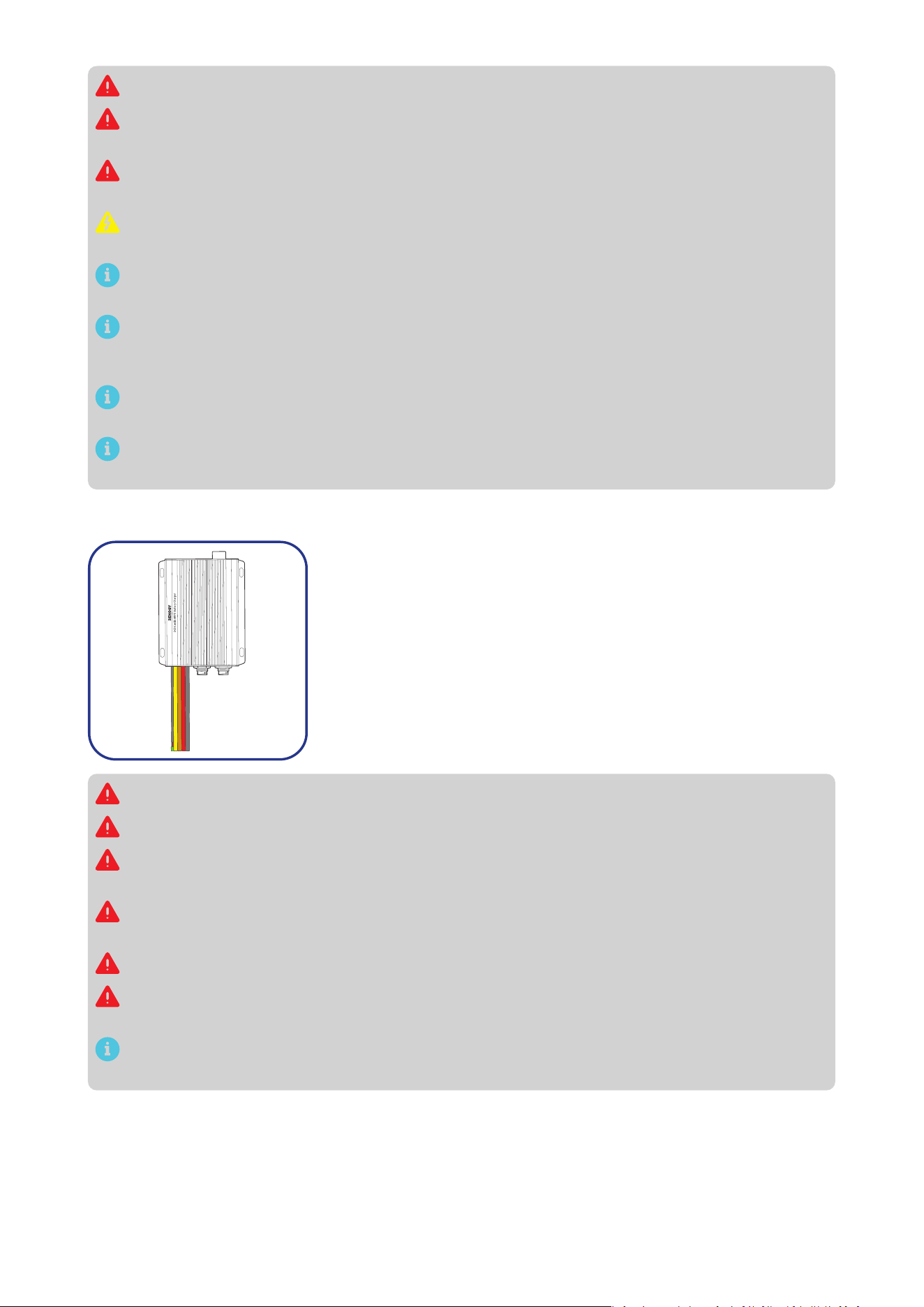
3.4. Check the Battery Charger
Inspect the battery charger for any visible damage including cracks,
dents, deformation, and other visible abnormalities. All connector
contacts shall be clean, free of dirt and corrosion, and dry.
Do not use the battery charger if there is any visible damage.
Do not puncture, drop, crush, penetrate, shake, strike, or step on the battery charger.
There are no serviceable parts in the battery charger. Do not open, dismantle, repair, tamper with,
or modify the battery charger.
Confirm the polarities of the devices before connection. A reverse polarity contact can result in
damage to the battery charger and other connected devices, thus voiding the warranty.
Do not touch the connector contacts while the battery charger is in operation.
Wear proper protective equipment and use insulated tools during installation and operation. Do
not wear jewelry or other metal objects when working on or around the battery charger.
Do not dispose of the battery charger as household waste. Comply with local, state, and federal
laws and regulations and use recycling channels as required.
— 7 —
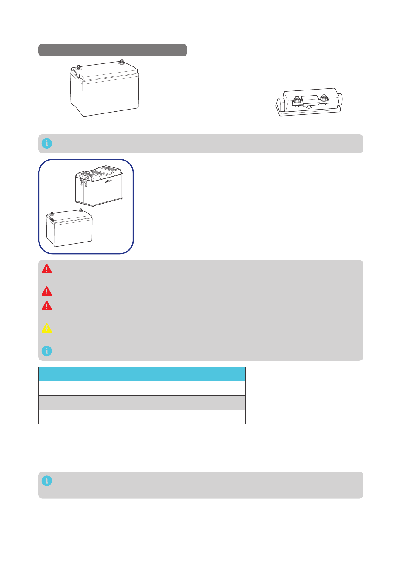
3.5. Check the Auxiliary Battery
Recommended Components & Accessories
*12V/24V Battery (11V to 32V) *ANL Fuse (60A) × 1
+
-
Components and accessories marked with “*” are available on renogy.com.
+
-
1. Inspect the battery for any visible damage including cracks,
dents, deformation, and other visible abnormalities. All terminals
shall be clean, free of dirt and corrosion, and dry.
The battery charger can only be connected to 12V or 24V deep-
cycle gel-sealed lead-acid batteries (GEL), flooded lead-acid
batteries (FLD), sealed lead-acid batteries (SLD/AGM) or lithium
iron phosphate batteries (LI).
Do not use the battery if there is any visible damage. Do not touch the exposed electrolyte or
powder if the battery housing is damaged.
When being charged, the battery may give off explosive gas. Make sure there is good ventilation.
Take care to use a high-capacity lead-acid battery. Be sure to wear protective goggles. If
carelessly getting electrolyte in your eyes, flush your eyes with clean water immediately.
Combine batteries in parallel or in series as needed. Prior to installing the battery charger, ensure
all battery groups are installed properly.
Read the user manual of the battery in use carefully.
Battery or Battery Bank System Voltage
Battery or Battery Bank System Voltage = System Voltage U
Batteries in Series Batteries in Parallel
System Voltage U: U1+U2+U3 System Voltage U: U1=U2=U3
2. This battery charger works
seamlessly with both 12V and
24V battery systems. Please
consult the battery manual
for accurate system voltage
information. Ensure that the
16V overvoltage protection is
not triggered for 12V systems
and the 32V protection is not
activated for 24V systems.
Read the battery user manual for battery voltage parameters, and calculate the voltage of the battery or
battery pack system according to the formula to ensure that it does not exceed 32V.
In the formula, U represents the battery voltage, and 1, 2, or 3 represents the battery number
respectively.
— 8 —
3. Inspect the ANL Fuses for any visible damage including cracks,
dents, deformation, and other visible abnormalities. All terminals
shall be clean, free of dirt and corrosion, and dry.
Do not use the ANL Fuses if there is any visible damage.
For details on how to install and use the ANL Fuse, see its user manual.
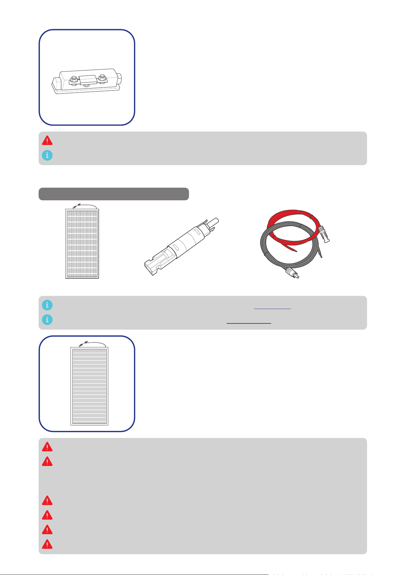
3.6. Check the Solar Panel(s)
Recommended Components & Accessories
*Solar Panel Extension Cables × 2
*Solar Panel (s)
*Solar Panel Fuse
Components and accessories marked with “*” are available on renogy.com.
For how to size solar panel extension cables, refer to “3.2. Size Wires” in this manual.
1. Inspect the solar panel for any visible damage including cracks,
dents, deformation, and other visible abnormalities. All connector
contacts shall be clean, dry, and free of dirt and corrosion.
Do not use the solar panel if there is any visible damage.
Cover the solar panel prior to connecting it to the battery charger to prevent any electrical current
or voltage from being generated or flowing through the system during the installation process.
This reduces the risk of electrical shocks or accidents while making connections, ensuring the
safety of the installer and the integrity of the equipment.
Do not install the solar panel on a surface constructed from combustible material.
Do not expose the solar panel to direct flame or heat sources.
Keep the solar panel out of the reach of children.
Keep the solar panel away from explosives and corrosive substances.
— 9 —
Do not step, walk, stand, or jump on the solar panel. Localized heavy loads may cause damage to
the solar cells, which will ultimately compromise the performance of the solar panel.
Do not bend the solar panel. Bending the solar panel will cause damage to the cells and affect
panel performance.
Do not immerse the solar panel in water.
Read the user manual of the solar panel carefully before installation.
The solar panels can be combined in parallel or in series as needed.
Identify the polarities (positive and negative) on the cables used for solar panels. A reverse
polarity contact may damage the unit.
Maximum Output Power
Maximum Output Power of Solar Panel or Solar Panel Array
= Maximum Solar Input Power W
Solar Panels in Series Solar Panels in Parallel
Maximum Output Power W:
W1+W2+W3
Maximum Output Power W:
W1+W2+W3
2. Read the user manual of the
solar panel for the maximum
output power, and calculate
the maximum output power of
solar panel or solar panel array
according to the formula. Ensure
that the maximum output power
of the solar panel/solar panel
array does not exceed 720W.
In the formula, W represents the output power of the solar panel, and 1, 2, or 3 represents the
solar panel number respectively.
Open Circuit Voltage
Open Circuit Voltage of Solar Panel or Solar Panel Array
= Open Circuit Voltage U
Solar Panels in Series Solar Panels in Parallel
Working Voltage U: U1+U2+U3 Working Voltage U: U1=U2=U3
3. Read the user manual of the
solar panel for the maximum
open circuit voltage, and
calculate the maximum open
circuit voltage of solar panel or
solar panel array according to
the formula. Ensure that the
open circuit voltage of the solar
panel/solar panel array does not
exceed 50V.
In the formula, 1, 2, or 3 represents the solar panel number respectively.
Short Circuit Current (Isc)
Short Circuit Current (Isc)
of Solar Panel or Solar Panel Array
= Short Circuit Current (Isc) I
Solar Panels in Series Solar Panels in Parallel
Short Circuit Current (Isc) I:
I1=I2=I3
Short Circuit Current (Isc) I:
I1+I2+I3
4. Read the user manual of the
solar panel for the short circuit
current (Isc), and calculate the
short circuit current (Isc) of
solar panel or solar panel array
according to the formula. Ensure
that the short circuit current of
the solar panel/solar panel array
does not exceed 48A.
In the formula, I represents the short circuit current (Isc) of the solar panel, and 1, 2, or 3
represents the solar panel number respectively.
Short circuit current is the abnormal flow of electric current in a power system, occurring
between phases or between phase and ground (or neutral) during operation, with values often
exceeding the rated current and dependent on the electrical distance from the short-circuit point
to the power source. For detailed information, please refer to the specific solar panel manual.
— 10 —
5. The appropriate current rating for the solar panel fuse should be
determined by multiplying the total short current amperage of
the solar panel array by 1.56.
Rated Current of the Solar Panel Fuse = Short Circuit Current (Isc)
of Solar Panel x 1.56
Inspect the solar panel fuse for any visible damage including
cracks, dents, deformation, and other visible abnormalities. All
terminals shall be clean, free of dirt and corrosion, and dry.
Do not use the solar panel fuse if there is any visible damage.
For details on how to install and use the solar panel fuse, see its user manual.
6. Inspect the Solar Panel Extension Cables for any visible
damage including cracks, dents, deformation, and other visible
abnormalities. All connector contacts shall be clean, dry, and free
of dirt and corrosion.
Do not use the solar panel extension cables if there is any visible damage.
3.7. Check the Alternator on Your Automobile
Recommended Components
*ANL Fuse (70A) × 1
Accessories marked with “*” are available on renogy.com.
The automobile alternator may be a smart alternator or a traditional alternator. The connection method
of a smart alternator or a traditional alternator depends on its parameters. Before installing the battery
charger, read the user manual of the vehicle or consult the vehicle supplier to determine the type of
alternator.
In addition, you can use a multimeter by yourself to measure the alternator to determine the type of
alternator.
1. Locate your main vehicle battery or the starter battery.
2. Start the engine. Ensure all any fans, radio, lights, and others are turned off.
3. Take a voltage reading across the main vehicle battery.
4. Leave the engine run for around 5 or 10 minutes, then repeat Step 3.
Taking a 12V system as an example, if the vehicle’s starter battery is 24V, the following parameters
should be multiplied by 2.
Readings around 14.4V DC indicates you most likely have a traditional alternator. If your readings are
around 12.5-13.5V, you most likely have a smart alternator.
— 11 —
In general, the working voltage of a traditional alternator ranges from 13.2V to 16V, and that of a
smart alternator ranges from 12V to 16V. Consult the vehicle supplier for help if necessary.
3.8. How to Install 15/32 in Lugs or 3/8 in Lugs?
0.4 in
(10 mm)
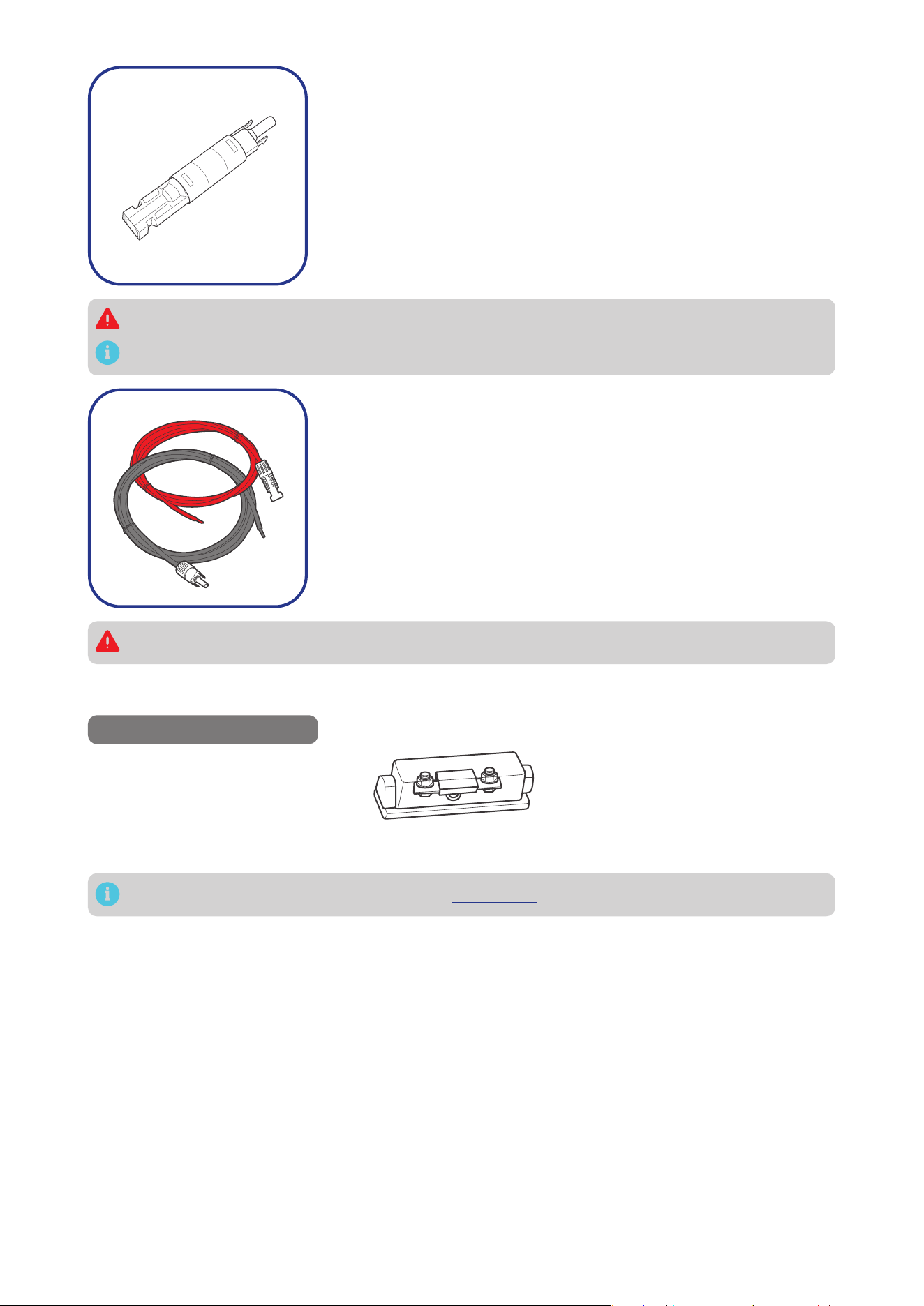
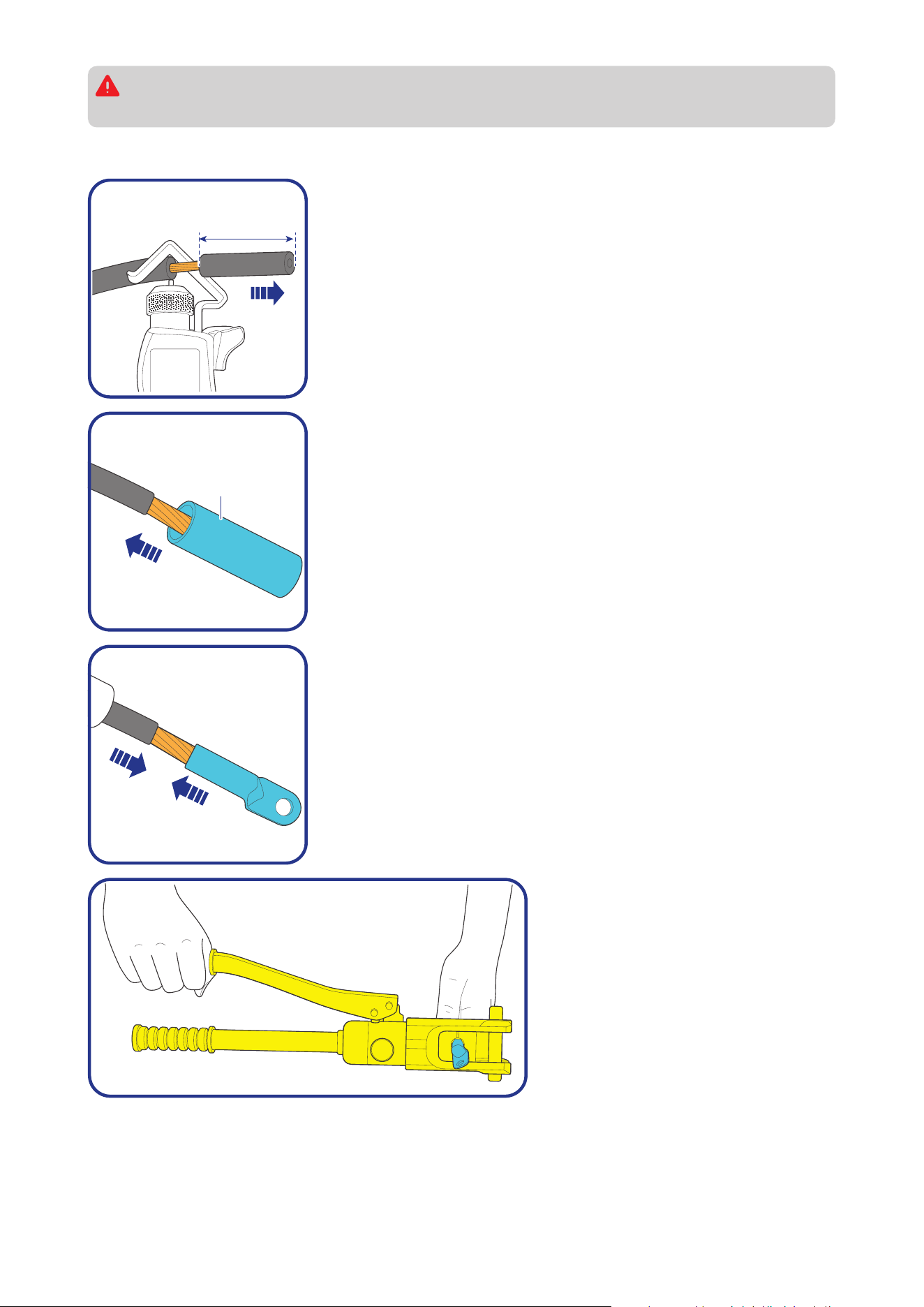
Step 1: Strip approximately 0.4 inches (10 mm) of insulation from
the end of a bare wire using a wire stripper.
Heat
Shrink
Tubing
Step 2: Thread the exposed bare wire through a piece of heat shrink
tubing.
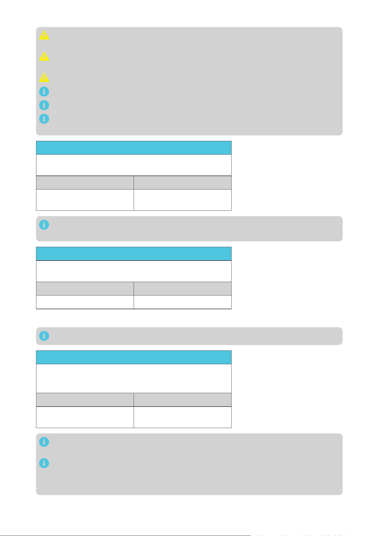
Step 3: Attach a 15/32-inch lug or 3/8-inch lug onto the end of the
bare wire.
Step 4: Securely crimp the lug
onto the bare wire using a manual
hydraulic pliers.
— 12 —
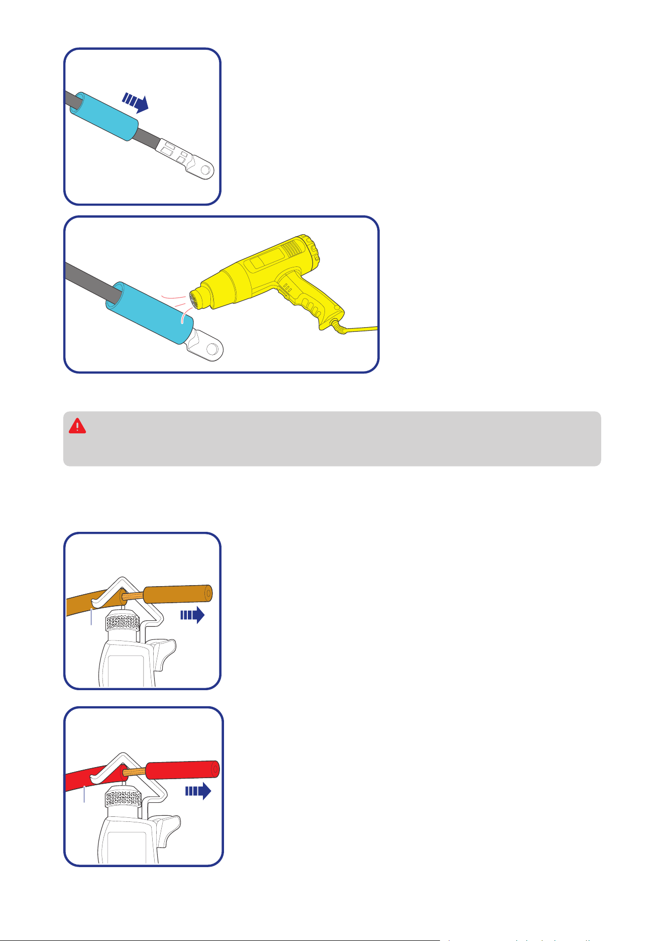
Step 5: Slide the heat shrink tubing over the 15/32-inch lug or 3/8-
inch lug.
Step 6: Apply heat to the heat shrink
tubing using a heat gun until it
shrinks and forms a tight seal.
3.9. How to Install Cables on the Battery Charger?
You are allowed to make connections using insulated conduit, junction boxes, or welding
methods. If the battery charger is installed outdoors, please ensure that the wiring connections
are waterproof.
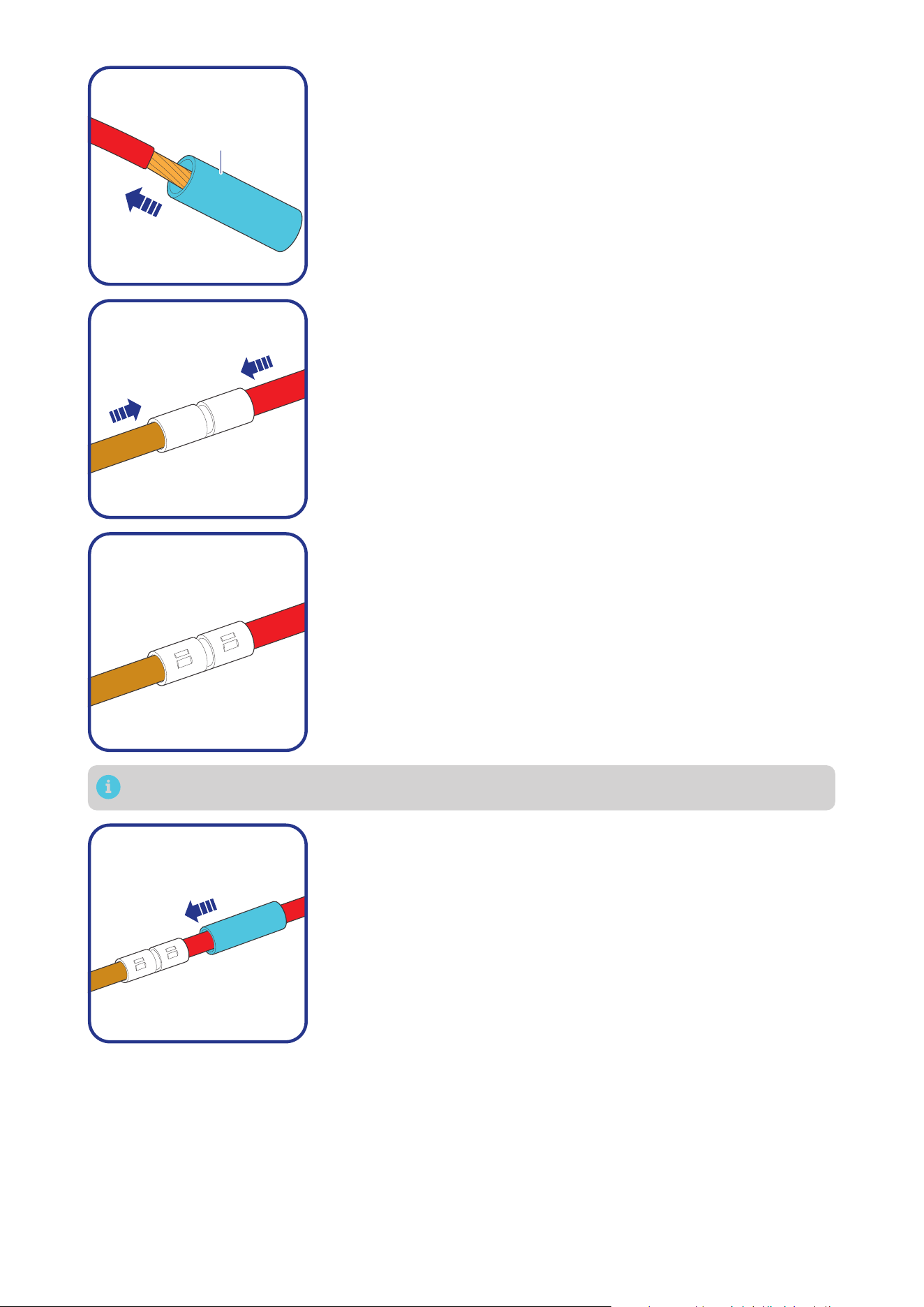
█
Positive Cable
The illustrations are based on the Positive Auxiliary Battery Cable. The butt-splice connectors we use in
the manual come in separate butt-splices and heat shrink tubings.
Battery
Charger
Step 1: Wear insulating gloves before wiring. Remove some
insulation from the end of the Positive Auxiliary Battery Cable based
on the length of the but-splice with a wire stripper.
Bare
Wires
Step 2: Remove some insulation from one end of a bare wire based
on the length of the but-splice with a wire stripper.
— 13 —
Heat
Shrink
Tubing
Step 3: Thread the exposed bare wire through a piece of heat shrink
tubing.
Step 4: Insert the Positive Auxiliary Battery Cable and bare wire into
the butt-splices.
Step 5: Securely crimp the butt-splices onto the cables using a
manual hydraulic pliers.
You can solder the wires to the butt-splice, ensure that a good connection is made.
Step 6: Slide the heat shrink tubing over the butt-splices.
— 14 —
Step 7: Apply heat to the heat shrink
tubing using a heat gun until it
shrinks and forms a tight seal.
█
Negative Cable
For the negative terminals, we recommend a busbar. Install the 3/8-inch lugs (M10 ring terminals) on
the solar panel, auxiliary battery, starter battery negative cables, and battery charger negative common
cable (black) on the busbar.
Busbar
(60A to 100A)
Solar Panel (s)
Auxiliary Battery
(12V / 24V)
Starter Battery
+
-
+
-
+
-
15/32 in Lug
(M12 Ring
Terminal)
15/32 in Lug
(M12 Ring
Terminal)
3/8 in Lug
(M10 Ring
Terminal)
— 15 —
4. Installation
To ensure safe and efficient operation of the battery charger and to avoid potential damage or hazards,
always follow the installation instructions in the sequence described in this manual.
4.1. Wear Insulating Gloves
Insulating Gloves
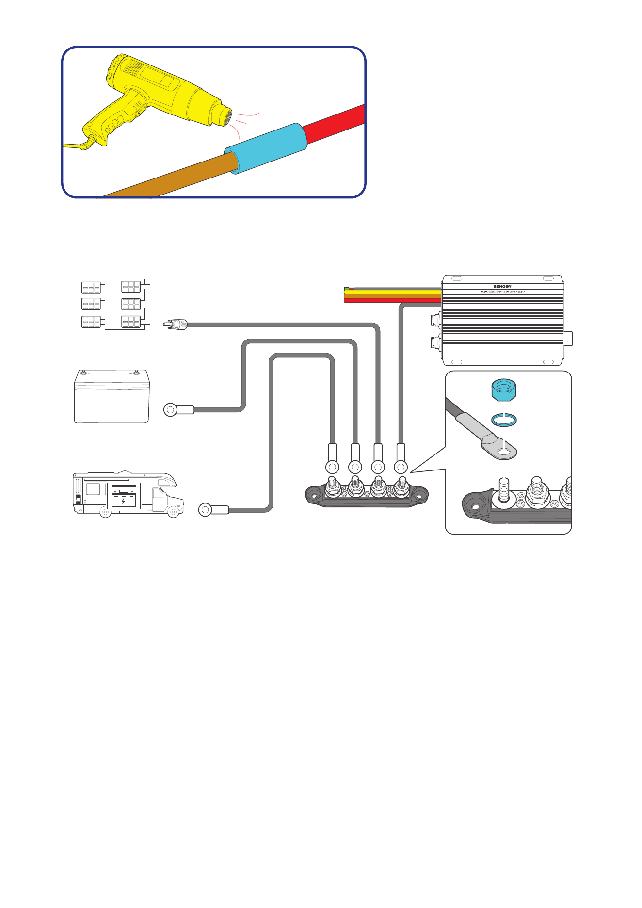
4.2. Connect the Battery Charger to a Busbar
Busbar
(60A to 100A)
3/8 in Lug
(M10 Ring Terminal)
Negative Common Cable (black)
Tug on cable to ensure firm connection.
— 16 —
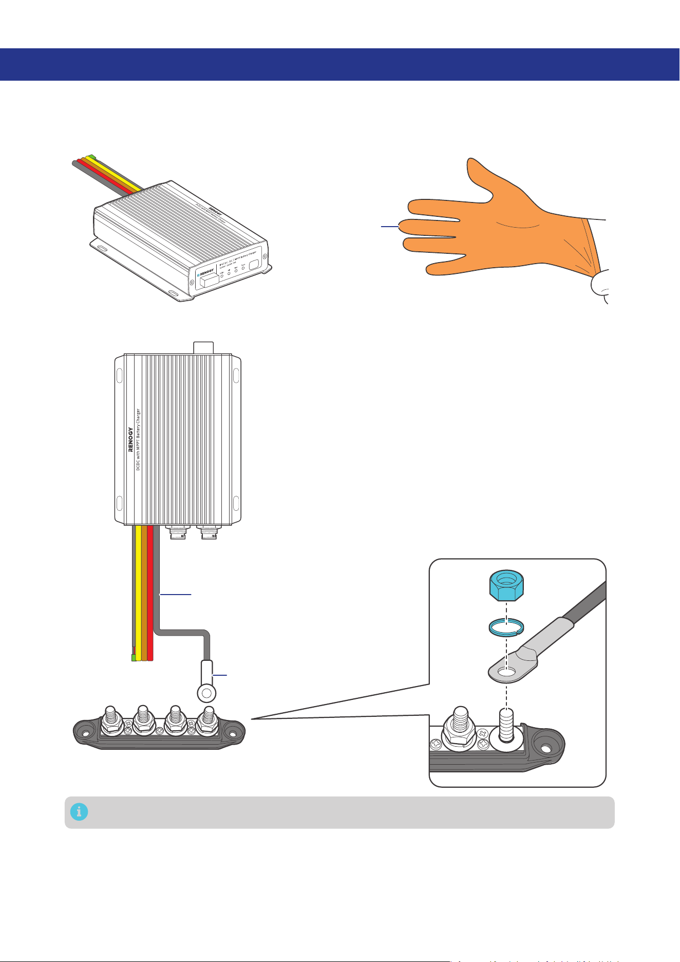
4.3. Connect the Battery Charger to an Auxiliary Battery
The battery charger can only be connected to 12V or 24V deep-cycle gel-sealed lead-acid batteries
(GEL), flooded lead-acid batteries (FLD), sealed lead-acid batteries (SLD/AGM) or lithium iron phosphate
batteries (LI).
Step 1: Connect one positive cable (red) to the Positive Auxiliary Battery Cable (brown) on the battery
charger.
Step 2: Connect the other end of the positive cable (red) to an ANL fuse.
Step 3: Connect the negative cable (gray) to the Busbar, connect the other end to the negative end of
an auxiliary battery.
Step 4: Connect the ANL fuse to the positive end of the auxiliary battery through the other positive
cable (red).
ANL Fuse (60A)
3/8 in Lug
3/8 in Lug
15/32 in Lug
-
+
1
2
12
Auxiliary Battery
++
-
STEP-1 Install cables on the battery charger
STEP-2 Install an ANL fuse
STEP-3 Install the cables on the battery
1 2
Positive Auxiliary
Battery Cable (brown)
of the Battery Charger
Positive Cable
(red bare wire)
-
Tug on all cables to ensure firm connection.
Always connect the battery charger to a battery before connecting it to a solar panel to ensure
safe and efficient operation.
— 17 —
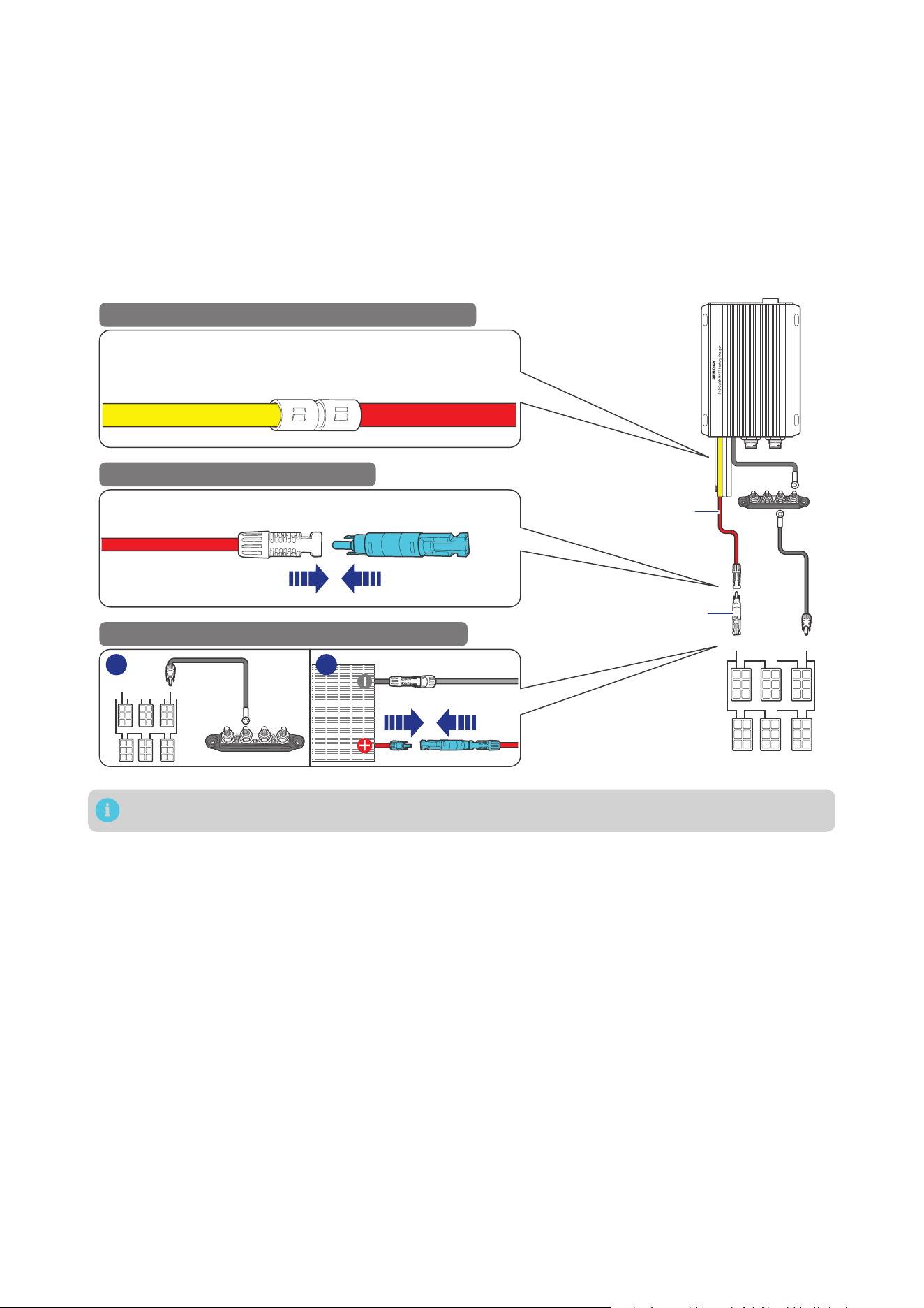
4.4. Connect the Battery Charger to a Solar Panel
Choose proper solar panels based on your power system. Connecting the battery charger to a solar
panel exceeding 720W (≤50V) results in damage to the battery charger.
Step 1: Connect the positive Solar Panel Extension Cable to the Positive Solar Cable (yellow) on the
battery charger.
Step 2: Connect the other end of the positive Solar Panel Extension Cable to a solar panel fuse.
Step 3: Connect the negative Solar Panel Extension Cable to the Busbar, connect the other end to the
negative end of a solar panel.
Step 4: Connect the solar panel fuse to the positive end of the solar panel.
Positive Solar
Cable (yellow)
of the Battery Charger
Solar Panel
Extension Cable
Solar Panel
Extension
Cables
Solar Panel (s)
+
-
STEP-1 Install cables on the battery charger
STEP-2 Install a solar panel fuse
STEP-3 Install the cables on the solar panel
1 2
Solar Panel Extension Cable Solar Panel Fuse
-
Solar Panel Fuse
Tug on all cables to ensure firm connection.
— 18 —
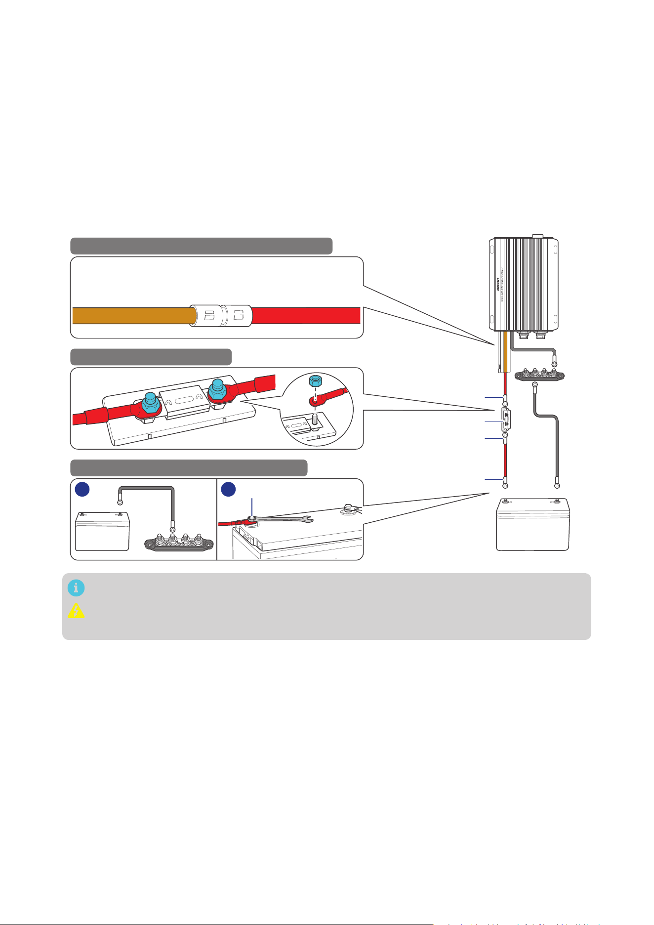
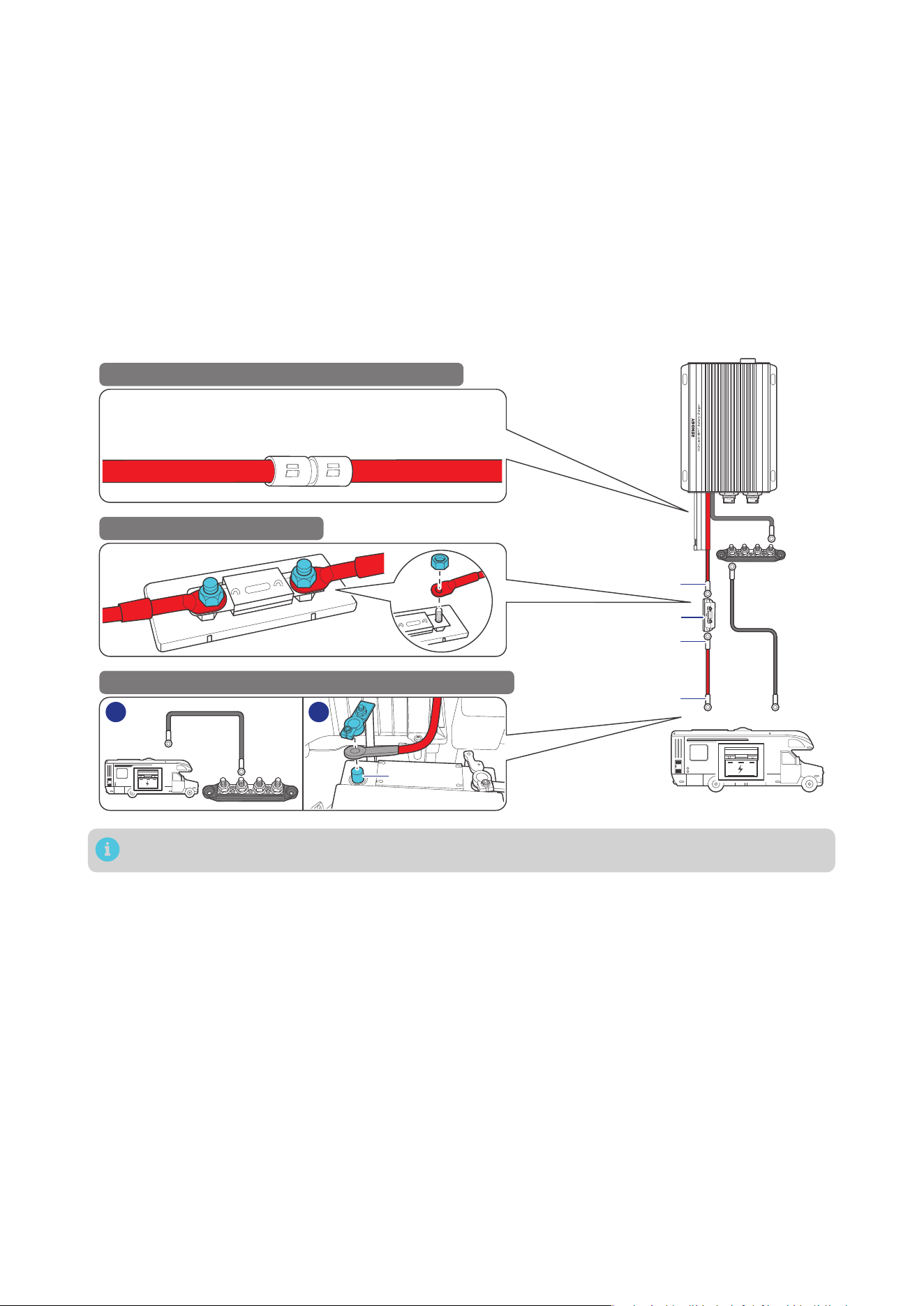
4.5. Connect the Battery Charger to a Starter Battery
Before installing the charger, consult your vehicle’s user manual or contact the vehicle manufacturer to
ensure that the output current ranges from 75A to 100A.
The starter battery stops charging the auxiliary battery when the starter battery voltage drops below
12.7V for 12V systems or 25.4V for 24V systems.
Step 1: Connect one positive cable (red) to the Positive Starter Battery Cable (red) on the battery
charger.
Step 2: Connect the other end of the positive cable (red) to an ANL fuse (70A).
Step 3: Connect the negative cable (gray) to the Busbar, connect the other end to the negative end of
your starter battery.
Step 4: Connect the ANL fuse to the positive end of the starter battery through another positive cable
(red).
Positive Starter
Battery Cable (red)
of the Battery Charger
Positive Cable
(red bare wire)
-
ANL Fuse (70A)
Starter Battery
+
+
-
STEP-1 Install cables on the battery charger
STEP-2 Install an ANL fuse
STEP-3 Install the cables on the RV starter battery
1 2
3/8 in Lug
3/8 in Lug
15/32 in Lug
Tug on all cables to ensure firm connection.
— 19 —
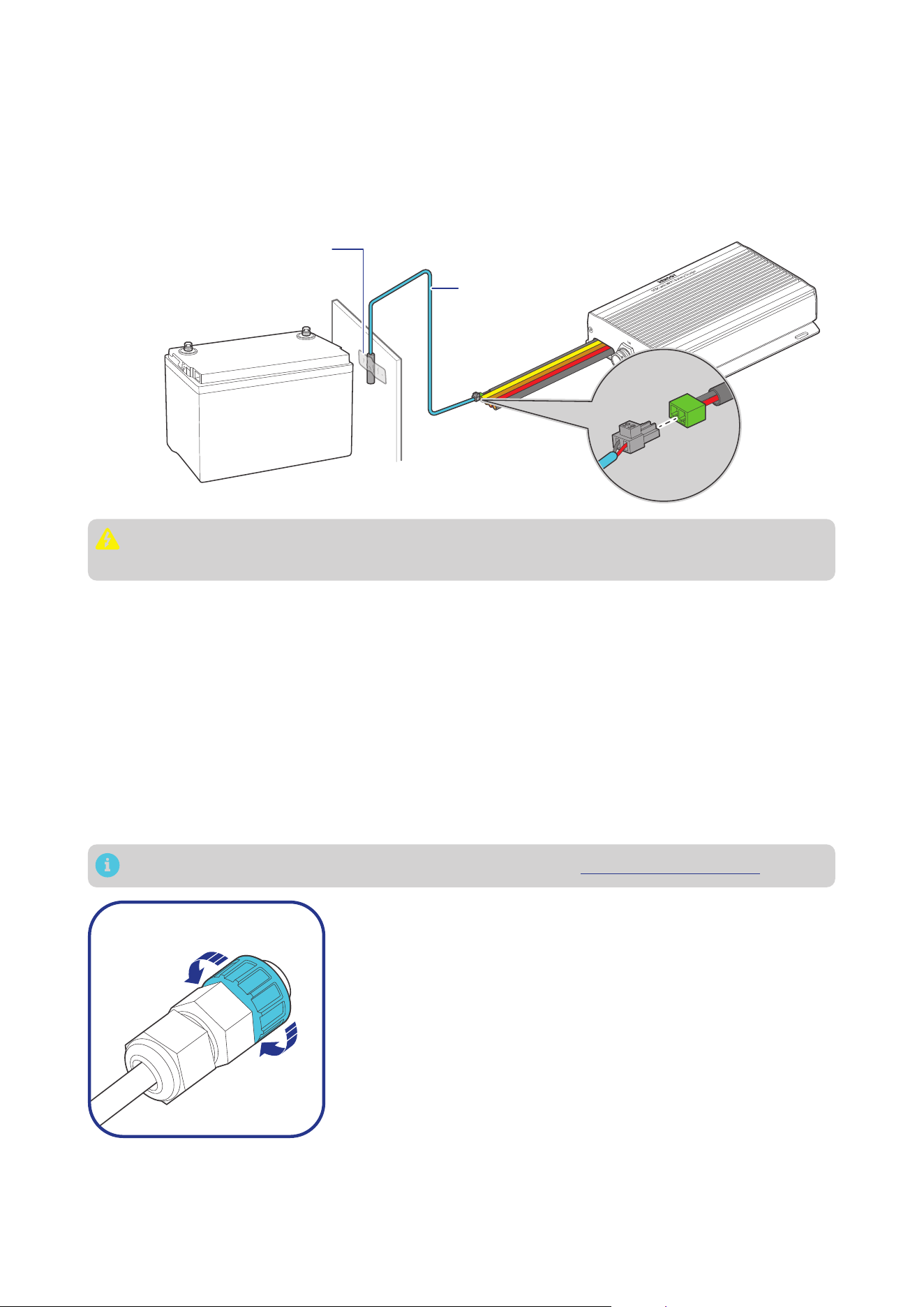
4.6. Install a Battery Temperature Sensor
The temperature sensor measures the surrounding temperature of the battery and compensates the
floating charge voltage when the battery temperature is low.
Step 1: Connect the battery temperature sensor to the Battery Temperature Sensor Cable on the
battery charger.
Step 2: Mount the other end of the sensor securely at a suitable location in close proximity to the
battery.
+
-
Mount the sensor securely
at a suitable location in
close proximity to the battery.
Battery
Temperature
Sensor
Do not use the temperature sensor on a LiFePO4 (LFP) battery which comes with a battery
management system (BMS).
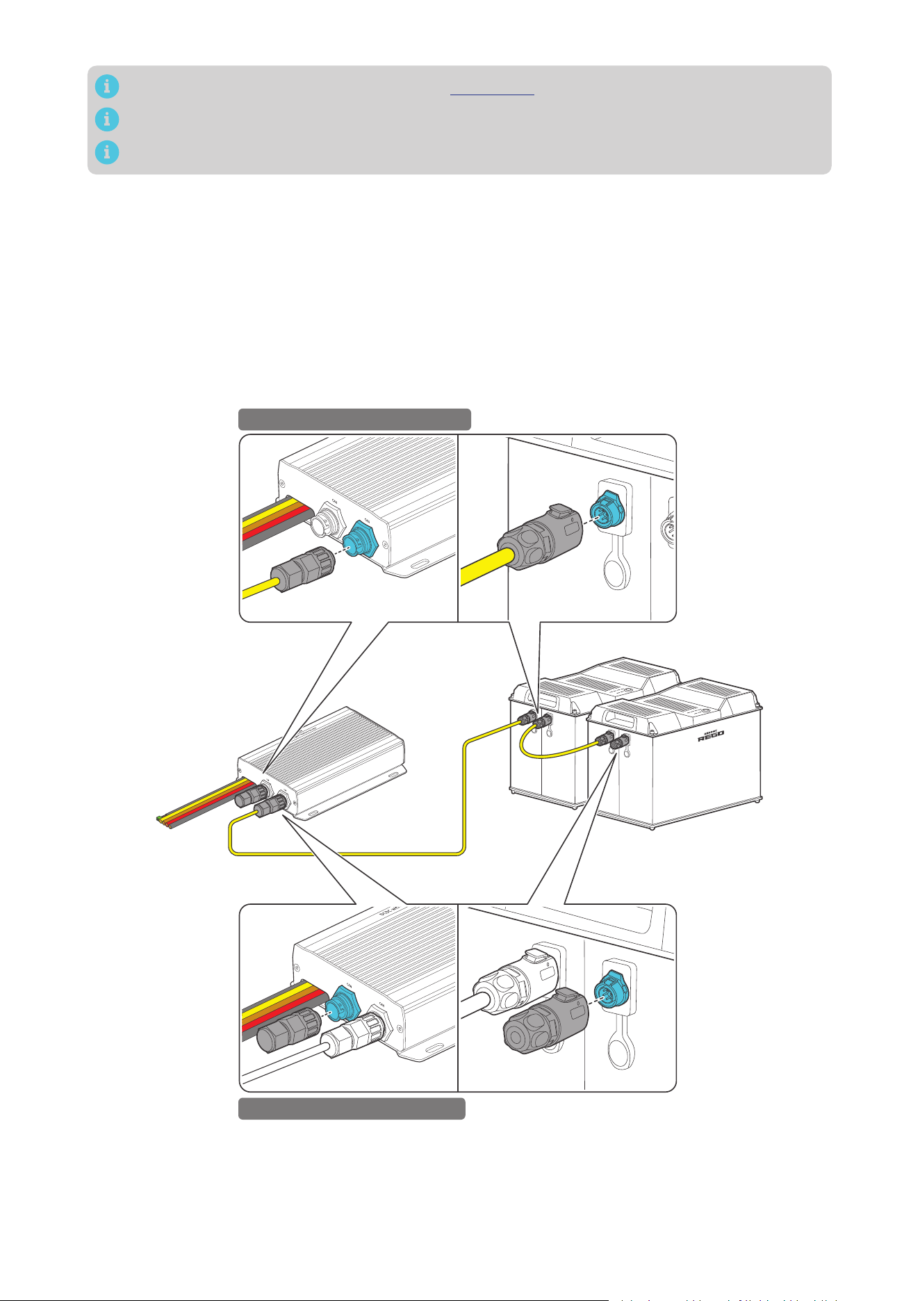
4.7. CAN Communication Wiring (Optional)
The 12V/24V 50A IP67 Dual Input DC-DC On-Board with MPPT Battery Charger can communicate with
other Renogy devices supporting CAN communication and monitoring devices through CAN (common
area network) bus, also known as RV-C, enabling safe operation, smart control, remote monitoring, and
programmable settings.
You can connect the battery charger to other Renogy devices supporting CAN communication for
real-time inter-device data communication through either of the CAN Communication Ports. 7-Pin
CAN Communication Terminal Plugs and 7-Pin CAN Communication Terminal Plug adapter cables are
required for the wiring.
The wiring details vary depending on the wiring schemes. This user manual elaborates on inter-device
wiring in two schemes: backbone and daisy chain.
For technical support from Renogy, please contact us through renogy.com/contact-us/.
To properly connect or disconnect the 7-Pin CAN Communication
Terminal Plug to or from the battery charger, you should
1. Ensure that the plug is oriented vertically toward the CAN
Communication Port.
2. Rotate the terminal fixing nut to loosen or secure the plug.
Shaking the terminal plug while plugging or unplugging it is not
allowed.
█
Backbone Network
Ensure 120
Ω
terminating resistors are installed at both ends of the RV-C bus for successful
communication with Renogy devices supporting CAN communication. If the RV user manual does not
determine if the RV-C bus has a built-in 120
Ω
termination resistor, call the RV manufacturer to confirm.

— 20 —
If the RV-C bus does not have a built-in 120
Ω
termination resistor, the battery charger will not
communicate properly with other Renogy devices supporting CAN communication. Please use
the Daisy Chain Network for communication connections.
Connect devices to the battery charger according to the wiring diagram provided by the RV
manufacturer. Choose proper communication cables according to your specific demands.
Recommended Tools & Accessories
*7-Pin CAN Communication Terminal Plug
to Bare Drop Cable(s)
Drop Plugs Split Joint Pliers
Accessories marked with “*” are available on renogy.com.
The 7-Pin CAN Communication Terminal Plug to Bare Drop Cable is only for use with the battery
charger. Please refer to the user manual of other devices for the communication cable types they
require.
The drop cable shall not exceed 19.6 feet (6 m), and the RV-C bus shall not exceed 98.4 feet (30 m).
Choose the appropriate drop plugs that are compatible with the drop sockets used on the
RV-C bus. Different RV manufacturers may use different types of drop sockets for inter-device
communication connections. If you are unsure about the correct drop plug selection, consult
with the RV manufacturer. In this manual, the Mini-Clamp II plug (4-pin) is used as an example.
Different Drop Plugs follow different pinouts. Crimp the Drop Plugs on the Drop Cables
following the correct pinout. If you are not sure about the Drop Plug pinout, check with the RV
manufacturer.
Step 1: Install the Drop Plugs on the bare end of the 7-Pin CAN Communication Terminal Plug to Bare
Drop Cable. The yellow CAN_H wire goes to pin 2, the green CAN_L wire goes to pin 3. Leave pin
1 and pin 4 empty.
Step 2: Squeeze the crimp areas of the Drop Plugs with the Split Joint Pliers.
Step 3: Locate the drop tap (not included) on the RV-C bus that is the closest to the installation site of
the battery charger. The drop taps are usually located above the entry door, in the bathroom, or
under the bed in the RV.
Step 4: Connect the Drop Plugs on the drop cables and other Renogy devices supporting CAN
communication to the drop sockets on the drop tap.
Step 5: Insert the 7-Pin CAN Communication Terminal Plug into any of the CAN Communication Ports of
the battery charger.
If you fail to locate the drop taps, please contact the RV manufacturer for help.
Different drop taps are used on the RV-C bus by different RV manufacturers. This user manual
takes the 4-socket drop tap as an example.
— 21 —
1 2 3
4 3 2 1
STEP-1 Install Cables on the RV-C bus
STEP-2 Install Cable on the Battery Charger
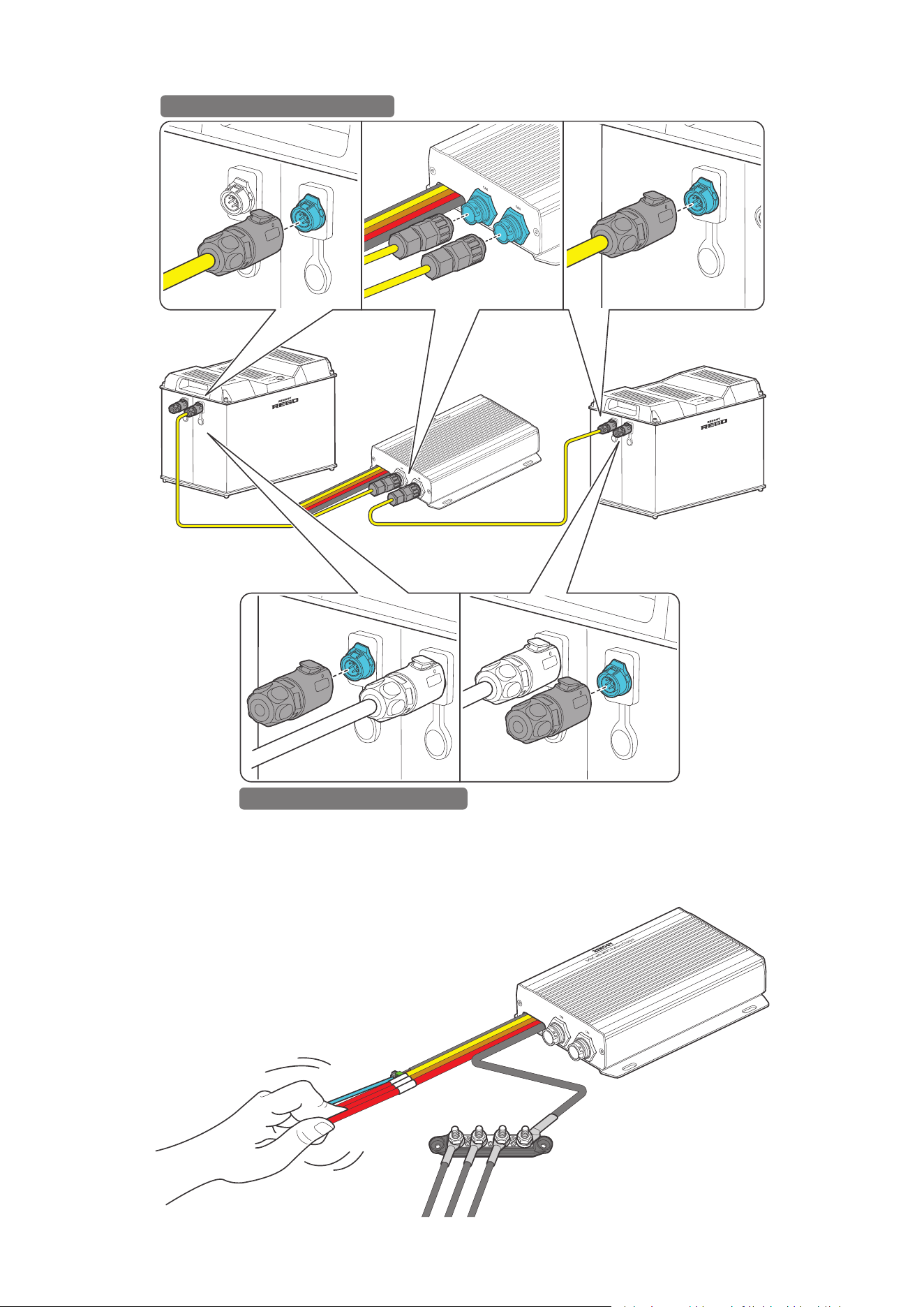
█
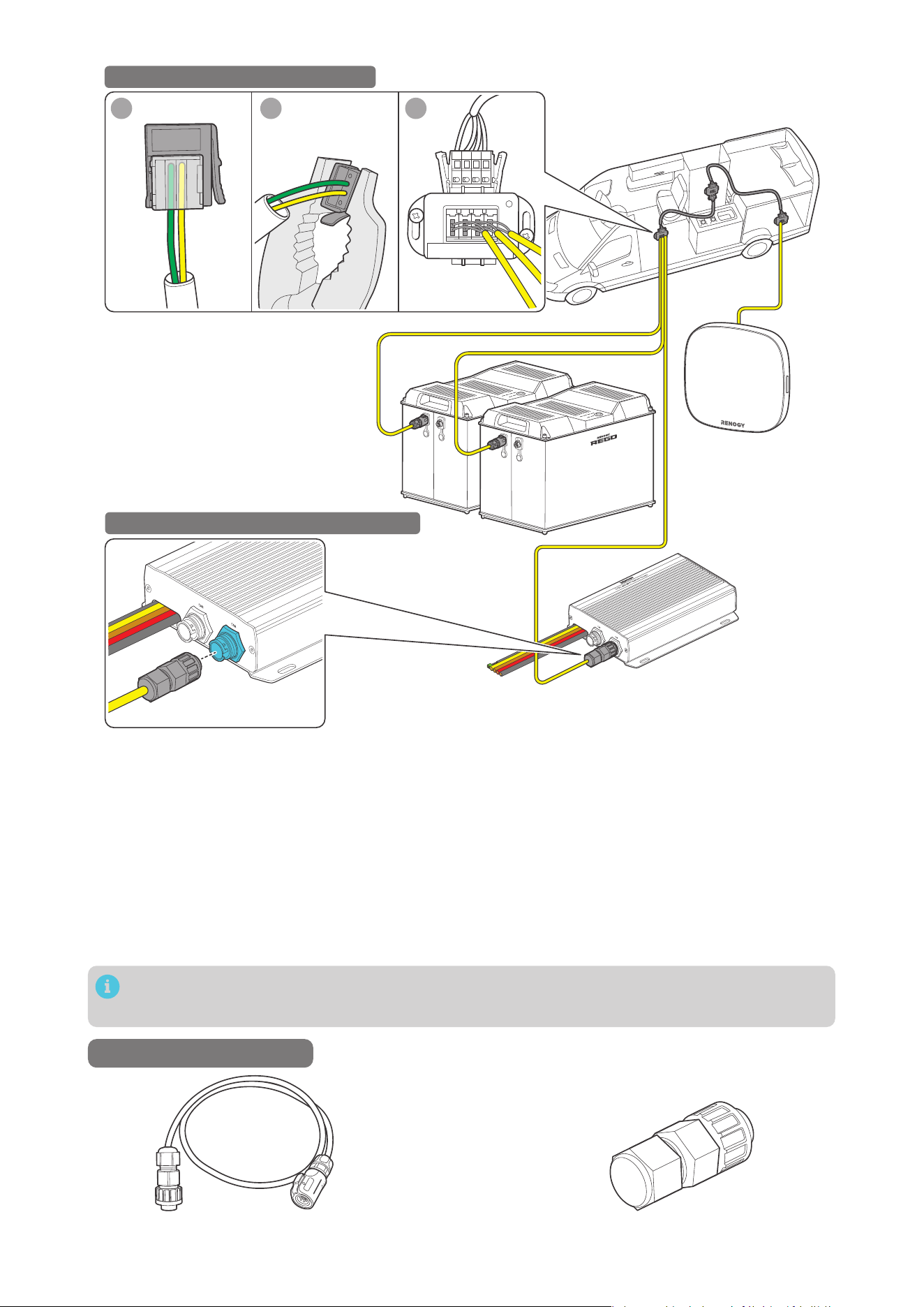
Daisy Chain Network
The daisy chain network applies to RVs that are not integrated with RV-C buses.
Please select the appropriate adapter cable based on the type of the CAN Communication Port specific
to the device. For example:
z
Battery Charger to RENOGY ONE: 7-Pin CAN Communication Terminal Plug to RJ45 Communication
Adapter Cable
z
Battery Charger to REGO devices: 7-Pin CAN Communication Terminal Plug to LP16 Plug (7-Pin)
Communication Adapter Cable
z
Battery Charger to Renogy Combiner Box: 7-Pin CAN Communication Cable(s)
This section is based on an 7-Pin CAN Communication Terminal Plug to LP16 Plug (7-Pin)
Communication Adapter Cable.
Recommended Accessories
*7-Pin CAN Communication Terminal Plug to
LP16 Plug (7-Pin) Communication Adapter Cable(s)
*7-Pin CAN Communication Terminal Plug
— 22 —
Accessories marked with “*” are available on renogy.com.
The communication cable should be less than 19.6 feet (6 m).
Choose proper terminal plugs based on the specific CAN ports.
The quantity of adapter cables and plugs varies based on the position of the battery charger in the
daisy chain network. When the battery charger is positioned at either the first or the last device in the
daisy chain network, one 7-Pin CAN Communication Terminal Plug and one adapter cable are required.
In scenarios where the battery charger is located in the middle of the daisy chain network, two adapter
cables are needed.
Step 1: Connect devices in series with the battery charger through either of the CAN Communication
Ports with the Communication Cable(s) (sold separately).
Step 2: Plug the Terminator Plugs (sold separately) into the vacant CAN Communication Ports on the
first and last devices.
Battery Charger is Positioned at the First or Last in the Daisy Chain Network
STEP-1 Install Cables on devices
STEP-2 Install Plugs on devices
— 23 —
Battery Charger is in the Middle of the Daisy Chain Network
STEP-1 Install Cables on devices
STEP-2 Install Plugs on devices
4.8. Wire Inspection
Verify that all cable connections are firmly and securely fastened. This step is essential to prevent any
loose or unstable connections that could lead to operational issues or safety concerns.
— 24 —
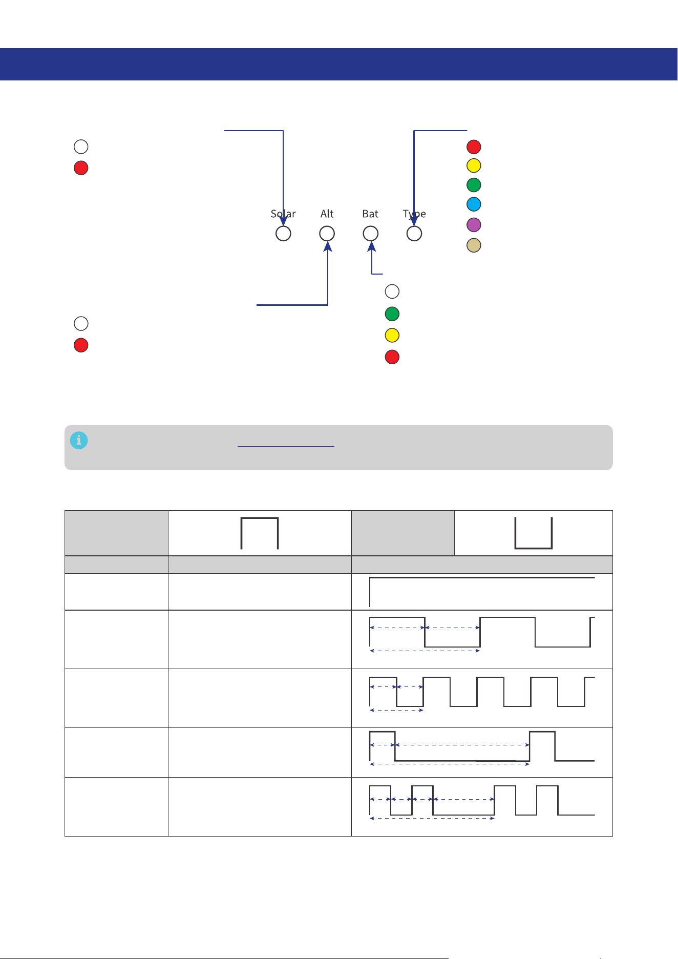
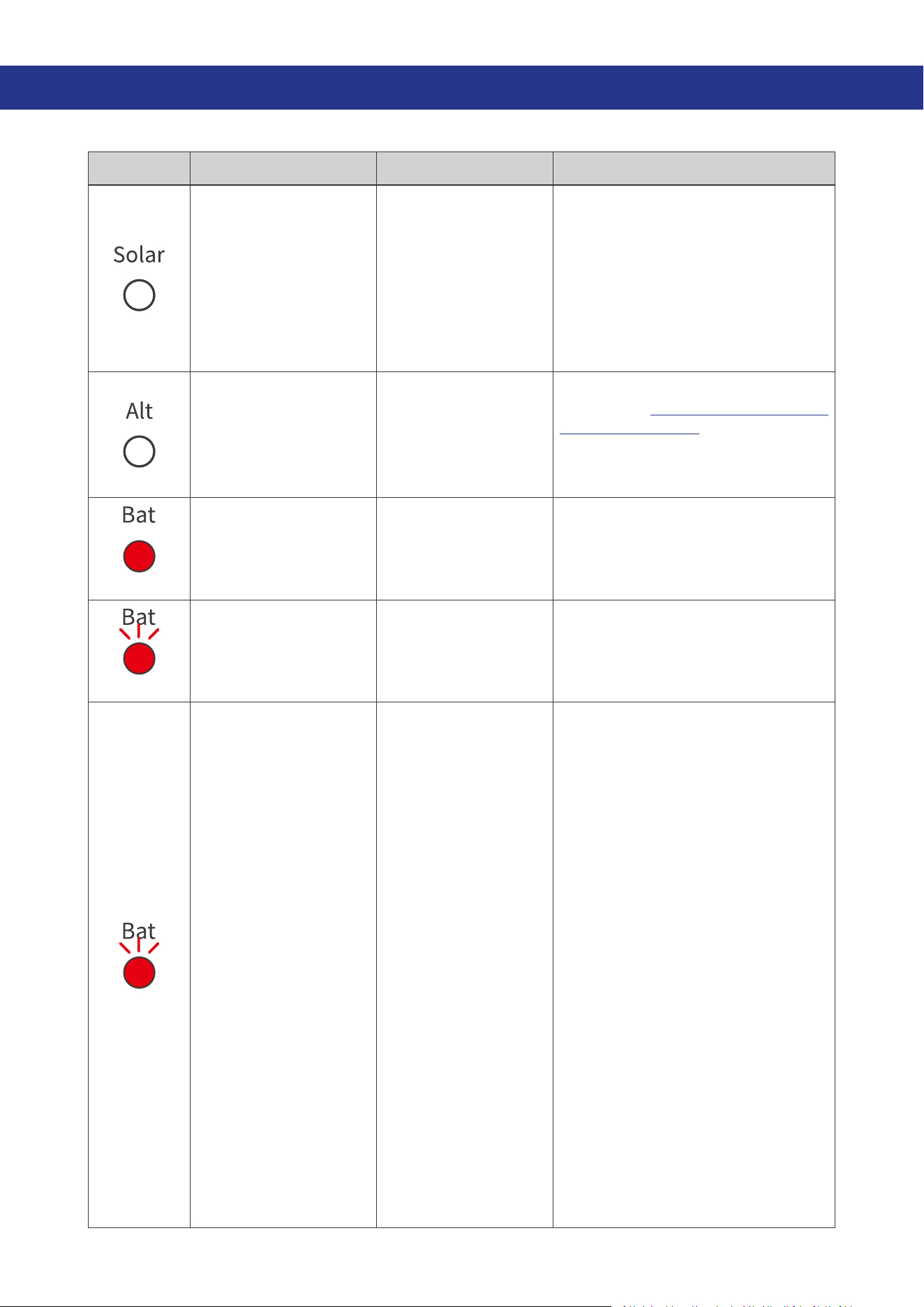
5. LED Indicators
The battery charger turns on automatically after power on with the LED indicators working in
accordance with the relative operating status.
Solar Charging Indicator
Solid: MPPT charging
Slow flash: Boost charging
Single flash: Float charging
Double flash: Limited-current
charging
Fast flash: Equalization
charging
O:
Not charging
Solid:
O:
Not charging
The starter battery connected to the
alternator is charging the auxiliary battery.
Slow flash:
The solar panel is charging the
starter battery.
Alternator Charging Indicator
Solid:
FLD
Solid:
GEL
Solid:
SLD/AGM
Solid:
12V LI
Solid:
24V LI
Solid:
User Mode
Solid:
O:
No battery detected
Full charge
Slow flash:
Overdischarge warning
Solid:
Normal battery voltage
Solid:
Undervoltage warning
Fast flash:
Overtemperature/
Overvoltage warning
Auxiliary Battery Indicator
Battery Type Indicator
If an error occurs, refer to “9. Troubleshooting” for details, or login to the Renogy app for
troubleshooting details.
Check out the graphic indications of ON, OFF, Solid, Slow Flash, Fast Flash, Single Flash, and Double
Flash of LEDs in the table below:
LED ON LED OFF
LED Pattern Description Graphic Expression
Solid
The LED remains continuously
illuminated without any variation.
Slow Flash
In this mode, the LED alternates
between being on and off at
a relatively slow and regular
interval of 1s.
1s
2s
1s
Fast Flash
In this mode, the LED alternates
between being on and off at a
relatively fast and regular interval
of 0.1s.
0.2s
0.1s0.1s
Single Flash
In this mode, the LED alternates
between brief 0.05s on followed
by a longer 1.95s off period.
0.05s 1.95s
2s
Double Flash
In this mode, the LED alternates
between brief 0.1s on-off cycles
followed by a longer 1.8s off
period.
0.1s 0.1s 0.1s
2.1s
1.8s
— 25 —
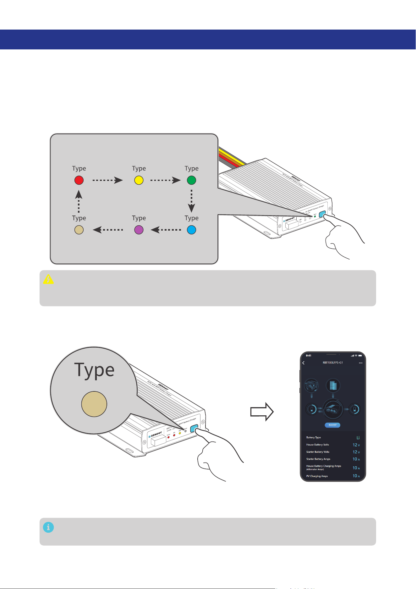
6. Configuration
6.1. Set a Battery Type
Upon installing the battery charger, set a correct battery type by using the Battery Type Setting Button.
A successful setting of the battery type is indicated by all LEDs illuminating from left to right (Solar to
Type).
Press the Battery Type Setting Button to switch between different battery types. The LED indicates
the battery type by displaying in different colors. For non-lithium batteries, the battery charger can
automatically detect their voltage (12V or 24V)
.
FLD
Flooded Battery
GEL
Gel Battery
SLD/AGM
Sealed Lead
Acid Battery
User Mode
Custom Battery
24V LI
24V Lithium
Battery
12V LI
12V Lithium
Battery
It is essential to ensure that the battery type setting is configured correctly to avoid any potential
damage to the battery charger because any damage to the battery charger resulting from an
incorrect battery type setting voids the warranty.
6.2. User Mode
Setting the battery type to User Mode allows you to customize your battery parameters. You can modify
the parameters in the Renogy app.
Before modifying battery parameters in User Mode, check the table below and consult the battery
manufacturer to check whether modification is allowed. Incorrect parameter setting will damage the
device and void the warranty.
In User Mode, when the Equalization Voltage matches the Boost Voltage and Float Voltage, the
activation mechanism for the lithium battery is initiated.
— 26 —
Maximum Combined
Charging Current
z
12V Battery: 50A. Adjustable at 50A, 40A, 30A, 20A, and 10A.
z
24V Battery: 25A. Adjustable at 25A, 20A, 15A, 10A, and 5A.
Equalization Voltage
1. For lead-acid batteries, please consult your battery manufacturer to
obtain the voltage value and then complete the settings according to
the feedback.
2. If equalization charging is not required, set the voltage to boost
voltage.
Boost Voltage
This value affects whether the battery can be fully charged. Please
consult the battery manufacturer and set the value properly.
Float Voltage
This value affects whether the battery can be fully charged. Please
consult the battery manufacturer and set the value properly.
Under Voltage Warning
This voltage value affects the life of the battery. Consult the battery
manufacturer and check if this voltage value needs to be set.
Low Voltage Shutdown
Boost Duration
Please consult the battery manufacturer if it is necessary to set this
parameter value.
Equalization Duration
Equalization Interval
6.3. Configure Charging Parameters
The table below illustrates the default and recommended parameters for batteries that can be
connected to the battery charger. The parameters may vary depending on the specific battery you use.
Read the user manual of the specific battery or contact the battery manufacturer for help if necessary.
Before modifying battery parameters, check the table below first. Incorrect parameter setting will
damage the device and void the warranty.
Read the user manual of the battery when customizing a preset battery. Incorrect battery type
selection damages the battery charger and voids the warranty.
The battery charger has a User Mode, and the specific default parameter values and customizable
parameters should be primarily based on the actual displays in the Renogy app or Renogy ONE.
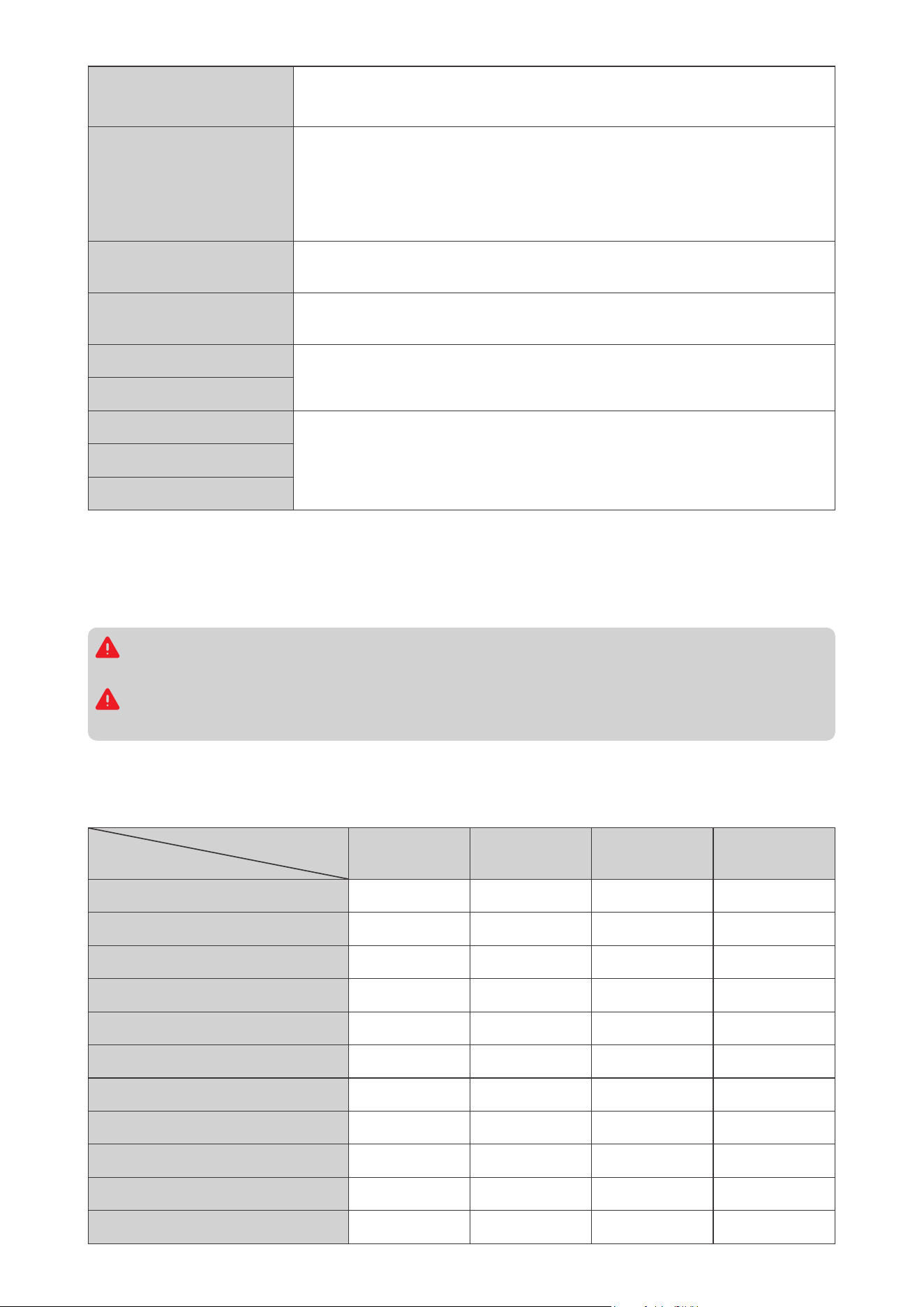
This table assumes default parameters for a 12V system. If the system voltage is 24V, double the values.
Battery Type
Parameters
SLD/AGM GEL FLOODED LI (LFP)
Overvoltage Shutdowm 16.0V 16.0V 16.0V 16.0V
Equalization Voltage 14.6V — 14.8V —
Boost Voltage 14.4V 14.2V 14.6V 14.4V
Float Voltage 13.8V 13.8V 13.8V —
Boost Return Voltage 14.1V 13.9V 14.3V 14.1V
Low Voltage Reconnect 12.6V 12.6V 12.6V 12.6V
Undervoltage Recover 12.2V 12.2V 12.2V 12.2V
Undervoltage Warning 12.0V 12.0V 12.0V 12.0V
Low Voltage Shutdown 11.0V 11.0V 11.0V 11.0V
Boost Duration 120 min 120 min 120 min —
Equalization Duration 120min — 120 min —

— 27 —
Battery Type
Parameters
SLD/AGM GEL FLOODED LI (LFP)
Equalization Interval 30 days — 30 days —
Temperature Compensation -3 mV / °C / 2V -3 mV / °C / 2V -3 mV / °C / 2V —
6.4. Activate Lithium Batteries
The battery charger can activate connected lithium batteries. Lithium batteries may enter sleep mode
when the in-built protection is triggered. In such case, the battery charger provides a small current to
reactivate the sleeping lithium battery. The lithium battery can be charged normally after successful
activation.
By default, the lithium activation function is enabled in the battery charger. You can disable it in
the Renogy app.
█
Operation Condition
Set the battery type of the battery charger to LI or USER. For details, see “6.1. Set a Battery Type”.
█
Operation Logic
z
For 12V Lithium Battery
If the battery voltage drops below 9V, the battery charger automatically activates the activation
function (on the premise that the activation function is enabled in the Renogy app) and continues to
charge the battery using constant voltage until the battery voltage reaches 14.4V.
z
For 24V Lithium Battery
If the battery voltage drops below 18V, the battery charger automatically activates the activation
function (on the premise that the activation function is enabled in the Renogy app) and continues to
charge the battery using constant voltage until the battery voltage reaches 28.8V.
— 28 —
7. Monitoring
Depending on the specific application, the battery charger can establish either short-range or long-
range communication connections with monitoring devices. These monitoring devices facilitate real-
time monitoring, programming, and complete system management, offering comprehensive control
and enhanced flexibility.
Make sure the Bluetooth of your phone is turned on.
The version of the Renogy app might have been updated. Illustrations in the user manual are for
reference only. Follow the instructions based on the current app version.
Make sure that the battery charger is properly installed and powered on before it is paired with
the Renogy app.
To ensure optimal system performance, keep the phone within 10 feet (3 m) of the battery
charger.
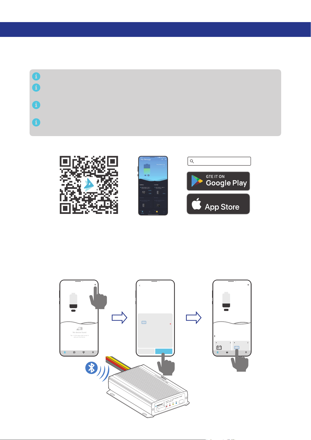
To ensure optimal connection performance, download the latest Renogy app. Login to the app with your
account.
Renogy App
Download on the
7.1. Short-Range Monitoring
If only short-range monitoring is required, connect the battery charger to the Renogy app directly
through the Bluetooth of your phone.
Step 1: Open the Renogy app. Tap + to search for new devices.
Step 2: Tap Confirm to add the newly found device to the device list.
Step 3: Tap the battery charger icon to enter the device information interface.
My Renogy
25%
A
Device
Devices
Battery
RBT12400LFPL-...
Battery Charger
Scene Community Me
DC-DC
%
25
A
0
-
No device found
Tap + in the upper-right corner to
add your first device.
---
My Renogy
Time remaining
--
CommunityDevice Select Me
Cancel Confirm
RBT100LFPS-G1
DC-DC
Found Devices
HUB Mode
Searching for device
Please make sure:
1. Bluetooth on this phone/tablet is
turned on.
2. The device is running properly.
3. The device's Bluetooth is turned on.
Identifying device...
— 29 —
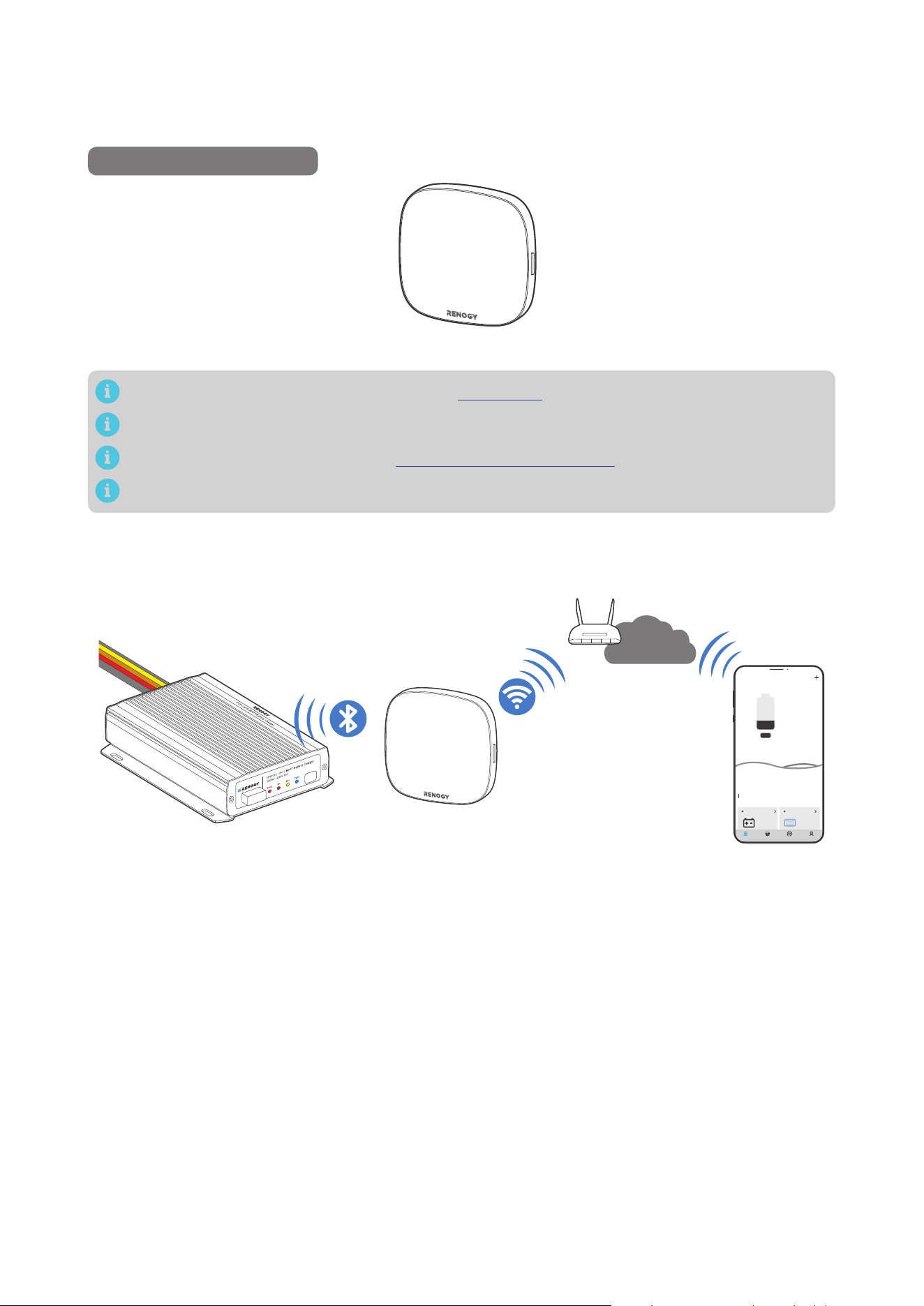
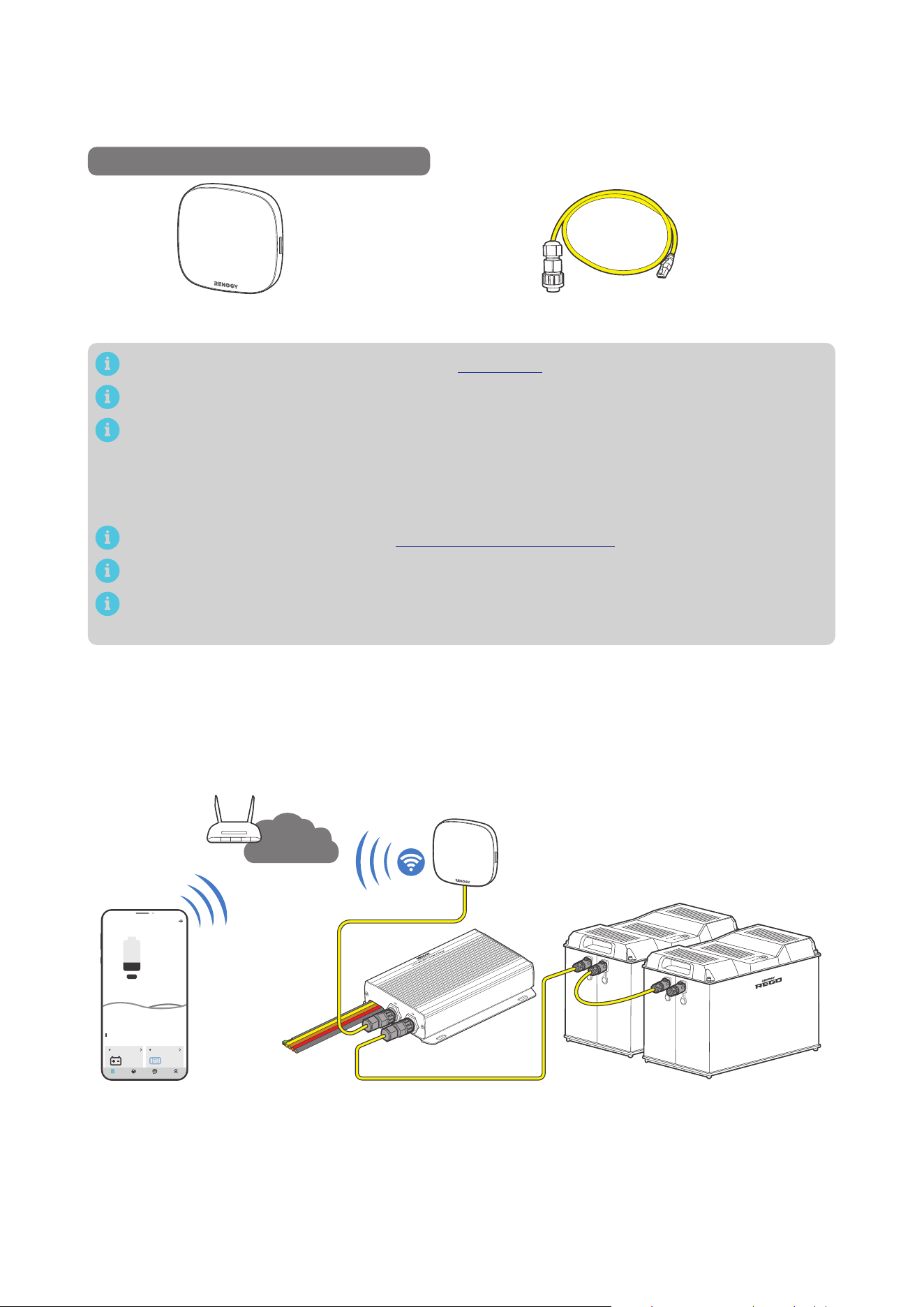
7.2. Wireless Long-Range Monitoring
If long-range communication and programming are required, connect the battery charger to Renogy
ONE (sold separately) through Bluetooth, and then pair Renogy ONE with the Renogy app.
Recommended Components
*RENOGY ONE Core
Components marked with “*” are available on renogy.com.
Make sure that the Renogy ONE is powered on before the connection.
For instructions on Renogy ONE, see Renogy ONE Core User Manual.
Make sure the battery charger does not communicate with any other device.
Step 1: Connect the battery charger to Renogy ONE through the Bluetooth of your phone.
Step 2: Pair the Renogy ONE with the Renogy app through Wi-Fi or by scanning the QR code in the
Renogy ONE. On Renogy ONE, go to “System > Settings > Pair with App” to get the QR code.
My Renogy
25%
A
Device
Devices
Battery
RBT12400LFPL-...
Battery Charger
Scene Community Me
DC-DC
%
25
A
0
-
Internet
— 30 —
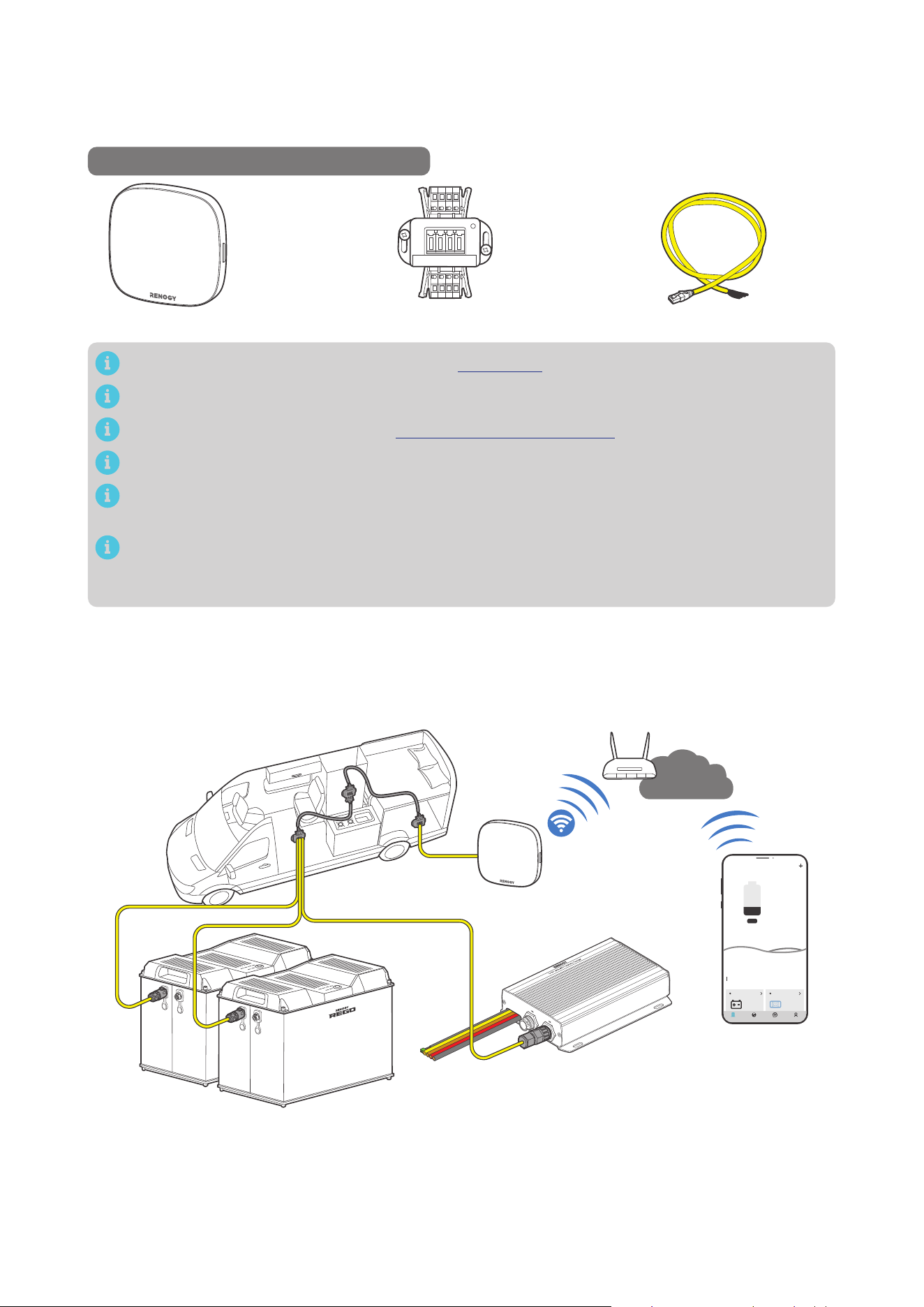
7.3. Wired Long-Range Monitoring (Backbone Network)
If long-range communication and programming are required, connect the battery charger to Renogy
ONE through a RJ45 Plug to Bare Drop cable, and pair Renogy ONE with the Renogy app.
Recommended Components & Accessories
RJ45 Plug to Bare Drop CableCommon Drop Tap*RENOGY ONE Core
Components marked with “*” are available on renogy.com.
Make sure that the Renogy ONE is powered on before the connection.
For instructions on Renogy ONE, see Renogy ONE Core User Manual.
Make sure the battery charger does not communicate with any other device.
Select the appropriate communication cable (sold separately) according to the distance between
devices. The communication cable should be less than 19.6 feet (6 m).
Different terminal block plugs are used on different Common Drop Taps and follow different
pinouts. If you are unsure about the pinout of the terminal block plug, contact the RV
manufacturer.
Step 1: Replace the terminated drop tap at either end of the RV-C bus with the Common Drop Tap (not
included). Secure the bare wires of the Drop Cable (not included) onto the terminal block plug of
the Common Drop Tap following the terminal block plug pinout. Plug the Drop Cable to the RJ45
port of Renogy ONE.
Step 2: Monitor and program the complete system on Renogy ONE or the Renogy app.
My Renogy
25%
A
Device
Devices
Battery
RBT12400LFPL-...
Battery Charger
Scene Community Me
DC-DC
%
25
A
0
-
Internet
— 31 —
7.4. Wired Long-Range Monitoring (Daisy Chain Network)
If long-range communication and programming are required, connect the battery charger to Renogy
ONE through wires, and pair Renogy ONE with the Renogy app.
Recommended Components & Accessories
*RENOGY ONE Core
*7-Pin CAN Communication Terminal Plug
to RJ45 Communication Adapter Cable
Components marked with “*” are available on renogy.com.
Make sure that the Renogy ONE is powered on before the connection.
The 7-Pin CAN Communication Terminal Plug to RJ45 Communication Adapter Cable is
exclusively designed for scenarios where the Battery Charger is positioned at the first or last in
the daisy chain network. If the Battery Charger is in the middle of the daisy chain network, please
select the appropriate adapter cable based on the CAN communication port type of the first or
last device.
For instructions on Renogy ONE, see Renogy ONE Core User Manual.
Make sure the battery charger does not communicate with any other device.
Select the appropriate communication cable (sold separately) according to the distance between
devices. The communication cable should be less than 19.6 feet (6 m).
Step 1: Remove the Terminator Plug from the Renogy devices supporting CAN communication at either
end of the daisy chain.
Step 2: Connect the Renogy ONE to the free CAN Communication Port on the Renogy devices
supporting CAN communication with the Communication Adapter Cable (sold separately).
Step 3: Pair Renogy ONE with the Renogy app. Monitor and program the complete system on the
Renogy ONE or the Renogy app.
My Renogy
25%
A
Device
Devices
Battery
RBT12400LFPL-...
Battery Charger
Scene Community Me
DC-DC
%
25
A
0
-
Internet
— 32 —
8. Working & Charging Logic
8.1. Automatic Voltage Matching Function
Whether you are connecting a 12V or 24V solar panel or starter battery, this battery charger will
automatically adjust the charging current and voltage values based on the rated voltage of the battery
being charged.
█
Charging the Auxiliary Battery
Nominal Voltage
Battery
Charger
Status
Charging
Voltage
Maximum
Charging
Current
Auxiliary
Battery
Solar Panel
Starter
Battery
12V
12V 12V -
12V 50A
12V 24V Steps down
24V 12V Steps down
24V 24V Steps down
24V
12V 12V Boost
24V 25A
12V 24V Boost
24V 12V Boost
24V 24V -
For details about when the solar panel and/or starter battery charge(s) the auxiliary battery, see
“8.2. Charging Logic” in this manual.
█
Charging the Starter Battery
Nominal Voltage
Battery
Charger
Status
Charging
Voltage
Maximum
Charging
Current
Starter
Battery
Solar Panel
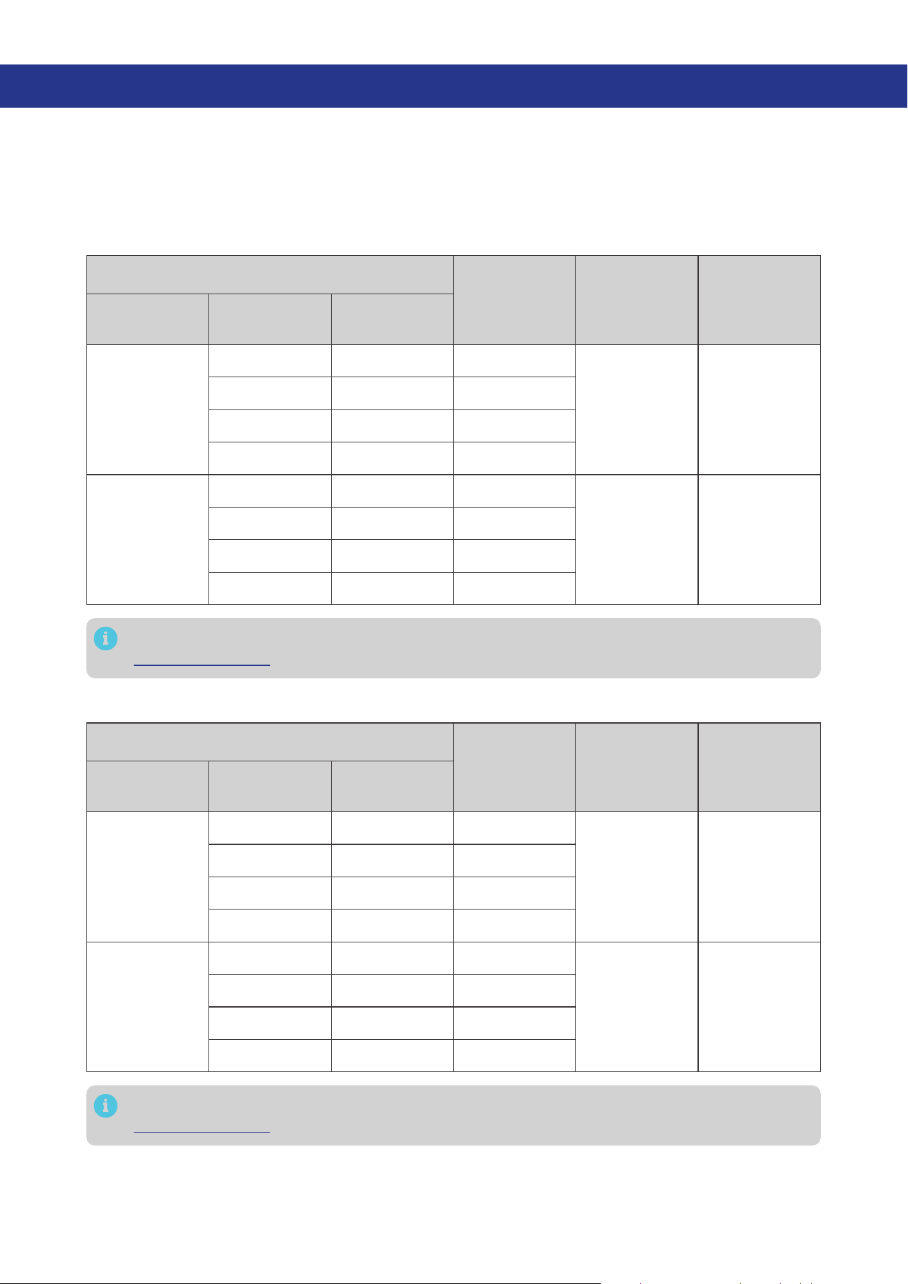
Auxiliary
Battery
12V
12V 12V -
12V 25A
12V 24V Steps down
24V 12V Steps down
24V 24V Steps down
24V
12V 12V Boost
24V 12.5A
12V 24V Boost
24V 12V Boost
24V 24V -
For details about when the solar panel and/or starter battery charge(s) the auxiliary battery, see
“8.2. Charging Logic” in this manual.
— 33 —
8.2. Charging Logic
The battery charger allows you to charge the auxiliary battery with a starter battery connected to an
alternator, with solar panels connected directly to the battery charger, or with both solar panel and
starter battery. The charging logic depends on the connection method.
The battery charger employs the “Solar Power Green Priority” logic for charging. The battery charger
determines the charging source by assessing the adequacy of solar power using the following formula.
Solar-generated Power = LowSolar Current Shuntdown x Output Voltage of the Battery Charger
You need to customize the “LowSolar Current Shuntdown” through the Renogy app.
Please refer to the actual displays in the Renogy app for the default value and setting range of
LowSolar Current Shuntdown.
The maximum charging power from the battery charger is not affected by the system voltage and
remains at 720W.
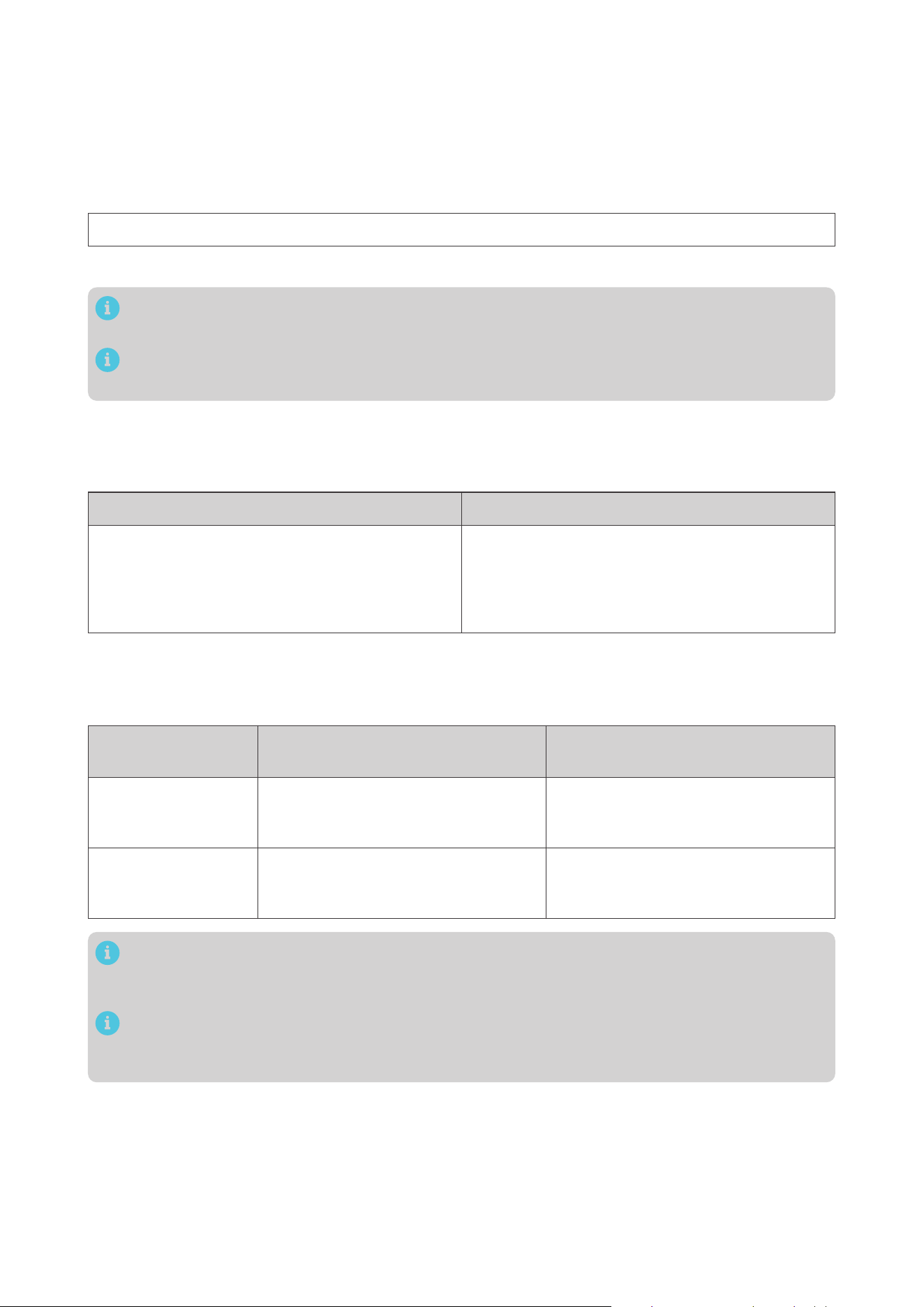
█
When Solar-Generated Power is Adequate
The battery charger charges the auxiliary battery using solar power only when the solar-generated
power is adequate. For details, see the table below:
Working Conditions Stop Conditions
Solar input voltage > 15V
After a delay of 10 seconds, the battery charger
will exclusively utilize the current provided by the
solar panel for charging.
Solar input voltage < 15V
The battery charger stops exclusively using the
solar panel for charging.
█
When Solar-Generated Power is Slightly Inadequate
The battery charger adopts both solar power and the starter battery to charge the auxiliary battery
when the solar-generated power is slightly inadequate.
Starter Battery
Nominal Voltage
Working Conditions Stop Conditions
12V
Solar input voltage < 15V
and
Starter battery voltage > 13.2V
Solar input voltage > 15V
or
Starter battery voltage < 12.7V
24V
Solar input voltage < 15V
and
Starter battery voltage > 26.4V
Solar input voltage > 15V
or
Starter battery voltage < 25.4V
The parameters in the above table are default values, and you can customize them through the
Renogy app. Please refer to the actual displays in the Renogy app for the specific customization
range.
Please consult the vehicle manufacturer before modifying the voltage values for the working
and stop conditions of the starter battery. Failure to do so may result in the starter battery being
depleted due to excessive discharge.

— 34 —
█
When Solar-Generated Power is Severely Inadequate
When solar power is severely inadequate, the battery charger charges the auxiliary battery by utilizing
only the starter battery.
Starter Battery
Nominal Voltage
Working Conditions Stop Conditions
12V
Solar output current <
LowSolar Current Shuntdown
and
Starter battery voltage > 13.2V
After 15 seconds, the battery charger
will utilize the current provided by the
starter battery for charging.
Solar output current >
LowSolar Current Shuntdown
or
Starter battery voltage < 12.7V
24V
Solar output current <
LowSolar Current Shuntdown
and
Starter battery voltage > 26.4V
After 15 seconds, the battery charger
will utilize the current provided by the
starter battery for charging.
Solar output current >
LowSolar Current Shuntdown
or
Starter battery voltage < 25.4V
The parameters “LowSolar Current Shutdown” and “Starter Battery Voltage” in the above table
are default values, and you can customize them through the Renogy app. Please refer to the
actual displays in the Renogy app for the specific customization range.
Please consult the vehicle manufacturer before modifying the voltage values for the working
and stop conditions of the starter battery. Failure to do so may result in the starter battery being
depleted due to excessive discharge.
█
Trickle Charging Starter Battery
Once the auxiliary battery is fully charged, the battery charger will utilize the solar panel to provide a
trickle charge to the starter battery.
Starter Battery
Nominal Voltage
Working Conditions Stop Conditions
Maximum Charging
Voltage for the
Starter Battery
12V
z
Auxiliary battery
fully charged
z
6V < Starter
Battery Voltage <
13.2V
The solar panel continuously
charges the starter battery for 1
minute, followed by a 30-second
pause. During this time, the voltage
of the starter battery is monitored.
If the starter battery voltage is
greater than 13.2V, charging will be
stopped. Otherwise, the charging
cycle will continue.
13.8V
24V
z
Auxiliary battery
fully charged
z
12V < Starter
Battery Voltage <
26.4V
The solar panel continuously
charges the starter battery for 1
minute, followed by a 30-second
pause. During this time, the voltage
of the starter battery is monitored.
If the starter battery voltage is
greater than 26.4V, charging will be
stopped. Otherwise, the charging
cycle will continue.
27.6V
— 35 —
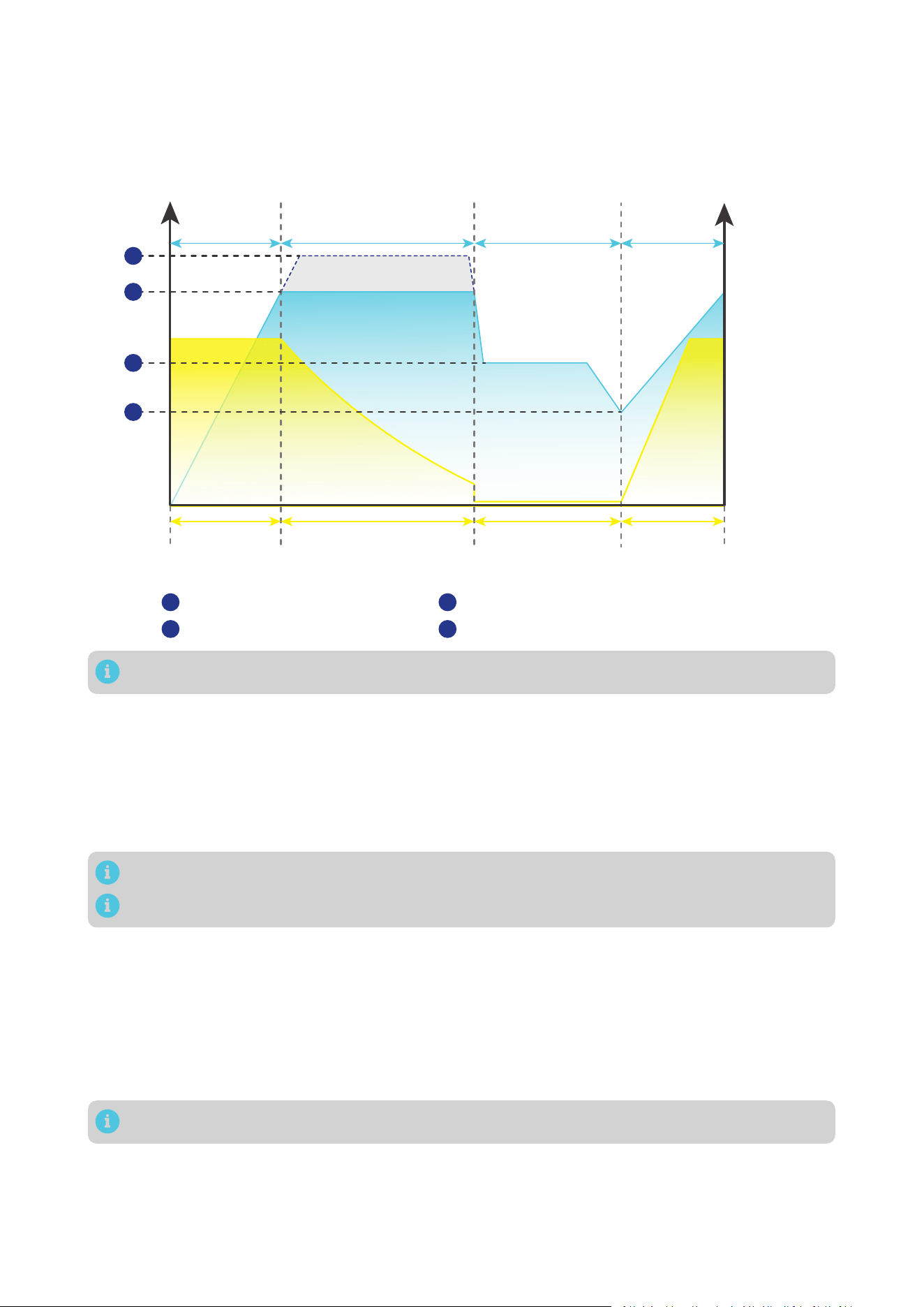
8.3. Battery Charging Stages
The battery charger utilizes cutting-edge MPPT technology to efficiently track the maximum power
output of solar panels in various conditions, ensuring real-time optimization. It also incorporates four
distinct charging stages: bulk, boost, float, and equalization.
U/V
Current
Voltage
I/A
Bulk
Charge
Stage
Reset to
Bulk
Charge
Stage
Boost Charge Stage
(Constant Voltage)
Float
Charge
Stage
Maximum
Current
Reduce Current Minimum Current Increase to
Maximum
Current
Equalization charging voltage
Boost charging voltage
Equalization
1
2
Float charging voltage
Low Voltage Disconnect Recover charging voltage
3
4
1
2
3
4
Adjust the time depending on the specific battery bank size.
█
Bulk Charge Stage
The battery charger will supply constant current until the battery voltage reaches the boost voltage.
█
Boost Charge Stage
The battery charger will supply constant voltage and reduce the current slowly through this stage.
Default boost duration: 2 hours. After this time, the charger will enter the float stage.
Boost Duration is not applicable to lithium batteries.
The stage is determined by internal software in the battery charger.
█
Float Charge Stage
During this stage the battery charger will supply a constant voltage which is determined by the battery
selected and will keep current at a minimum level. This stage acts as a trickle charger.
After reaching a constant voltage in the charging process, the battery charger reduces the voltage to
a float level. At this point, the battery is fully charged, and any excess current is converted to heat or
gas. The charger then maintains a lower voltage to offset power consumption, ensuring a full battery
capacity. If a load exceeds the charge current, the charger exits float mode and returns to bulk charging.
Float charging is not applicable to lithium batteries.
█
Equalization
This stage is only available for batteries with equalization, such as non-sealed
,
vented, flooded, and
wet cell lead acid batteries. During this stage the batteries are charged at a higher voltage than normal
and for most batteries this could cause damage. Refer to the user manual of the battery or contact the
battery manufacturer to see if this stage is needed.

— 36 —
During Equalization charging, the battery charger remains in this stage until sufficient charging
current is sourced from the solar panel. Note that there should be no load on the batteries during
Equalization charging..
Overcharging and excessive gas precipitation can harm battery plates, leading to material
shedding. Carefully review the battery’s specific requirements to avoid damage from prolonged
or excessively high Equalization charging .
Equalization may elevate battery voltage to levels that could damage sensitive DC loads. Ensure
that the allowable input voltages of all loads exceed the set voltage during Equalization charging..
— 37 —
9. Troubleshooting
This section discusses general troubleshooting tips specific to LED indicator status.
LED Fault Possible Cause Solution
Indicates the solar
charging fails to
function well.
z
The output voltage
of the solar panel is
below 15V.
z
The output voltage
of the solar panel
is excessively
high, triggering
overvoltage
protection.
z
For solar panel voltage under
15V, ensure there is no shade or
damage on the solar panel.
z
In scenarios where overvoltage
protection is triggered, check the
way in which the solar panels are
connected.
Indicates the starter
battery is not charging
the auxiliary battery.
The starter battery
voltage is below 13.2V.
Recheck the alternator type. For
details, see “3.7. Check the Alternator
on Your Automobile” in this manual.
If the actual output value from the
alternator is relatively low, modify the
cut-in voltage in the Renogy app.
Solid
An undervoltage
warning is triggered in
the auxiliary battery.
The auxiliary battery
voltage is low.
Charge the auxiliary battery
immediately.
Slow flash
An overdischarge
warning is triggered in
the auxiliary battery.
The auxiliary battery is
over-discharged.
Disconnect all loads from the
auxiliary battery, and charge it
immediately.
Fast flash
An overvoltage or
overtemperature
warning is triggered in
the auxiliary battery.
The auxiliary battery
is over-charged or at a
high temperature.
z
If the protection is triggered
without a Battery Temperature
Sensor installed, it indicates the
auxiliary battery is overcharged.
z
If the protection is triggered with
a Battery Temperature Sensor
installed, the auxiliary battery is
at a high temperature. Follow the
troubleshooting steps below:
1. Check the auxiliary battery
temperature in the Renogy app.
Temperatures higher than 149°F
(65°C) result in an overtemperature
alarm. Ensure the auxiliary battery
is installed in a well-ventilated site.
The warning for the auxiliary battery
temperature is cleared when it drops
to 140°F (60°C).
2. Check the auxiliary battery
voltage. For 12V batteries, the
auxiliary battery voltage should be
within 16V. For 24V batteries, the
auxiliary battery voltage should be
within 32V. Higher voltages trigger
an overvoltage alarm.
In such case, stop charging the
auxiliary battery.

— 38 —
-
The battery charger
stops charging.
Low-temperature
protection for the
auxiliary battery.
When the temperature of the
auxiliary battery drops below -31°F
(-35°C), the battery charger will
stop charging. Please warm up the
auxiliary battery, and charging will
resume once the temperature is
above -22°F (-30°C).
Over-temperature
protection for the
battery charger.
If the temperature of the battery
charger exceeds 212°F (100°C),
immediately provide ventilation to
cool down the charger.
The normal operating temperature
range for the battery charger is -31°F
to 212°F (-35°C to 100°C). When the
temperature exceeds 194°F (90°C),
the charger will decrease its load.
If the temperature exceeds 212°F
(100°C), the battery charger will stop
working.
For technical support, contact our technical service through renogy.com/contact-us.
— 39 —
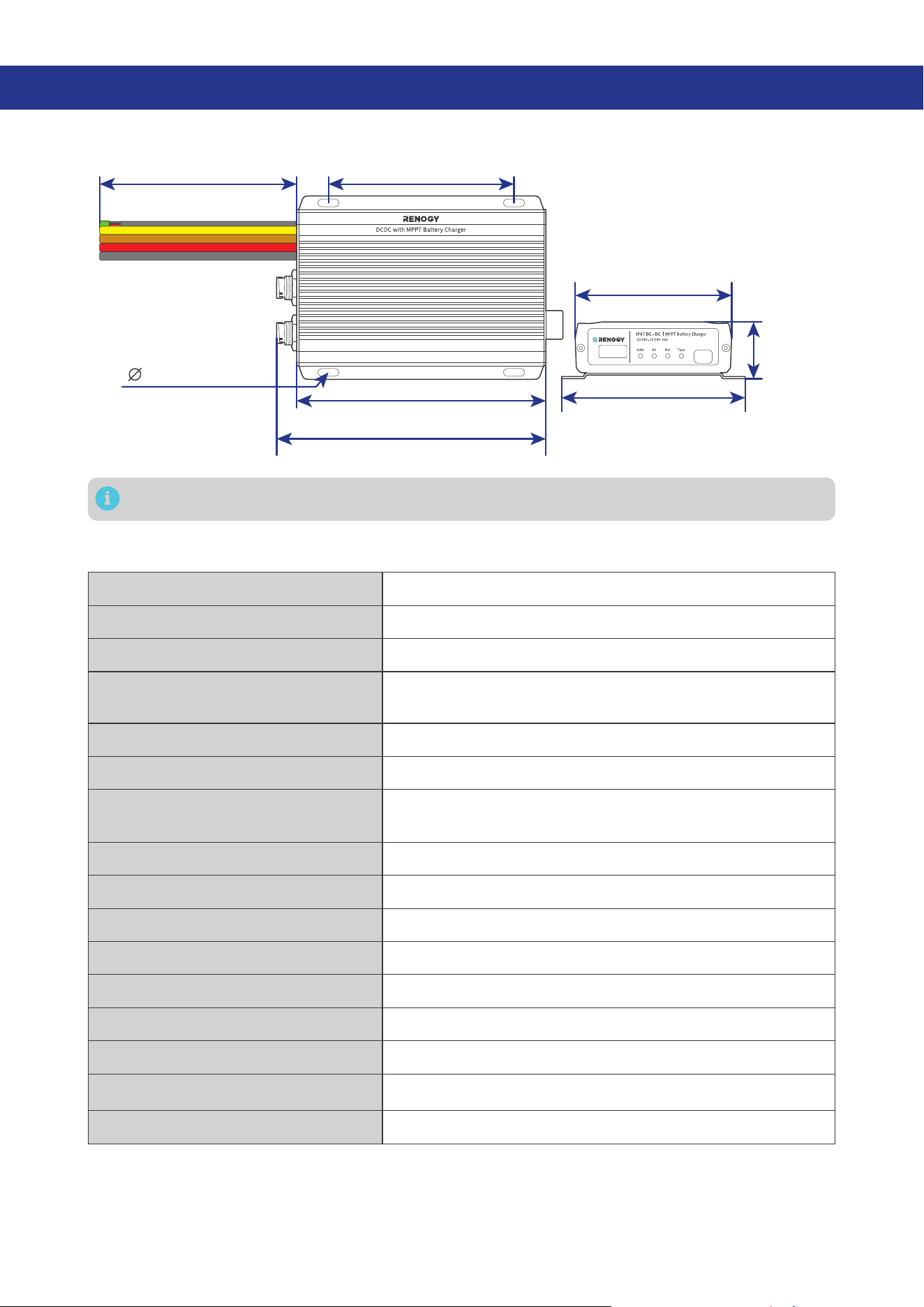
10. Dimensions & Specifications
10.1. Dimensions
6.5 in (165 mm)
7 in (178 mm)
4.84 in (123 mm)
0.2 in (5 mm)
4.06 in (103 mm)
4.72 in (120 mm)
1.46 in
(37 mm)
12 in (305 mm)
Dimension tolerance: ±0.2 in (0.5 mm)
10.2. Technical Specifications
System Voltage 12V/24V to 12V/24V DC
Nominal Output Power 720W
Battery Voltage Range 9V to 32V DC
Maximum Charging Current
50A@12V
25A@24V
Battery Type SLD, AGM, GEL, FLD, LI, and USER
Auxiliary Battery Charging Mode MPPT
Nominal Charging Efficiency
For 12V batteries: ≥94%
For 24V batteries: ≥92%
Max. Solar Input Voltage 50V
Max. Alternator Input Voltage 32V
Operating Temperature Range -31°F to 212°F / -35°C to 100°C
Storage Temperature -40°F to 212°F / -40°C to 100°C
No Load Current < 100mA
Humidity 0% to 95%, RH, no condensation
Dimensions 7.01 x 4.78 x 1.47 in / 178.2 x 121.5 x 37.5 mm
Weight 4.10 lb / 1.86 kg
Certifications CE, RoHS, and FCC Part 15 Class B

— 40 —
11. Maintenance
11.1. Inspection
For optimum performance, it is recommended to perform these tasks regularly.
z
Ensure the battery charger is installed in a clean, dry, and ventilated area.
z
Ensure there is no damage or wear on the cables.
z
Ensure the firmness of the connectors and check if there are any loose, damaged or burnt
connections.
z
Make sure the indicators are in proper condition.
z
Ensure there is no corrosion, insulation damage, or discoloration marks of overheating or burning.
z
If the battery charger is dirty, use a damp cloth to clean the outside of the device to prevent dust
and dirt from accumulating. Before the battery charger is powered on, make sure it is completely dry
after cleaning.
z
Make sure the ventilation holes are not blocked.
In some applications, corrosion may exist around the terminals. Corrosion can loosen springs
and increase resistance, leading to premature connection failure. Apply dielectric grease to
each terminals contact periodically. Dielectric grease repels moisture and protects the terminals
contacts from corrosion.
Risk of electric shock! Make sure that all power supplies are turned off before touching terminals
on the battery charger.
11.2. Cleaning
Follow the steps below to clean the battery charger regularly.
z
Disconnect all cables connected to the battery charger.
z
Wear proper protective equipment and use insulated tools during operation. Be careful when
touching bare terminals of capacitors as they may retain high lethal voltages even after power is
removed.
z
Wipe the housing of the battery charger and connector contacts with a dry cloth or nonmetallic
brush. If it is still dirty, you can use household cleaners.
z
Make sure the ventilation holes are not blocked.
z
Dry the battery charger with a clean cloth and keep the area around the battery charger clean and
dry.
z
Make sure the battery charger is completely dry before reconnecting it to the solar panel, battery and
AC input.
11.3. Storage
Follow the tips below to ensure that the battery charger is stored well.
z
Disconnect all cables connected to the battery charger.
z
By applying dielectric grease to each terminals, the dielectric grease repels moisture and protects
the connector contacts from corrosion.
z
Store the battery charger in a well-ventilated, dry, and clean environment with the temperature
between -40°F to 212°F or -40°C to 100°C.
— 41 —
12. Emergency Responses
In the event of any threat to health or safety, always begin with the steps below before addressing other
suggestions.
z
Immediately contact the fire department or other relevant emergency response team.
z
Notify all people who might be affected and ensure that they can evacuate the area.
Only perform the suggested actions below if it is safe to do so.
12.1. Fire
1. Disconnect all cables connected to the battery charger.
2. Put out the fire with a fire extinguisher. Acceptable fire extinguishers include water, CO₂, and ABC.
Do not use type D (flammable metal) fire extinguishers.
12.2. Flooding
1. If the battery charger is submerged in water, stay away from the water.
2. Disconnect all cables connected to the battery charger.
12.3. Smell
1. Ventilate the room. Disconnect all cables connected to the battery charger.
2. Ensure that nothing is in contact with the battery charger.
12.4. Noise
1. Disconnect all cables connected to the battery charger.
2. Make sure no foreign objects are stuck in the fan of the battery charger or the ring terminal.
The normal noise value of the battery charger is less than 30dB during operation. If the noise is
abnormal, contact our technical service through renogy.com/contact-us.
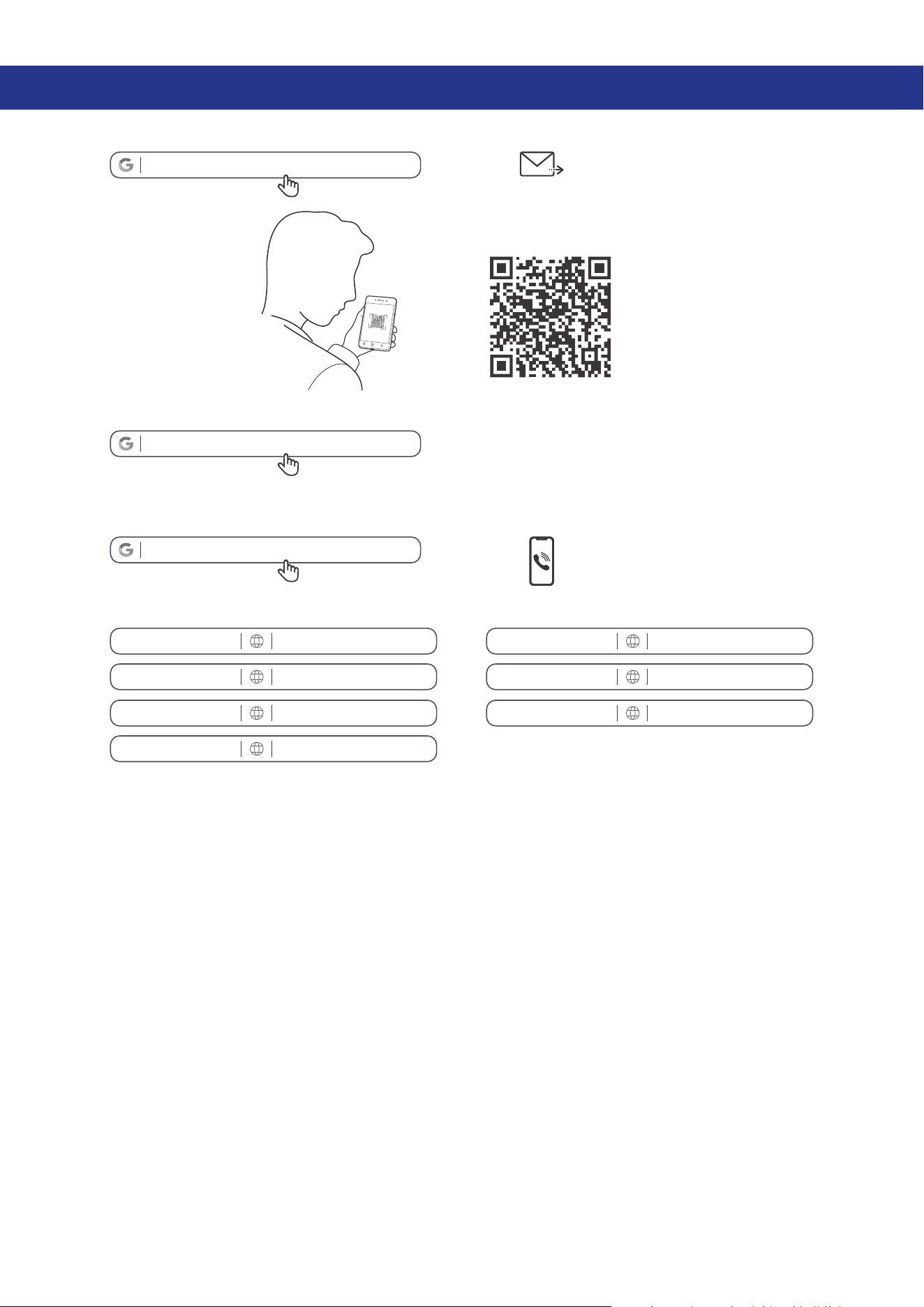
— 42 —
Renogy Support
To discuss inaccuracies or omissions in this quick guide or user manual, visit or contact us at:
renogy.com/support/downloads
contentservice@renogy.com
Questionnaire Investigation
To explore more possibilities of solar systems, visit Renogy Learning Center at:
renogy.com/learning-center
For technical questions about your product in the U.S., contact the Renogy technical support team
through:
renogy.com/contact-us
1(909)2877111
For technical support outside the U.S., visit the local website below:
Canada ca.renogy.com China www.renogy.cn
Australia
au.renogy.com Japan jp.renogy.com
Other Europe eu.renogy.com Germany de.renogy.com
United Kingdom uk.renogy.com

— 43 —
FCC
FCC Statement
This device complies with Part 15 of the FCC Rules. Operation is subject to the following two conditions:
(1) This device may not cause harmful interference.
(2) This device must accept any interference received, including interference that may cause undesired
operation.
Any Changes or modifications not expressly approved by the party responsible for compliance could
void the user’s authority to operate the equipment.
This equipment has been tested and found to comply with the limits for a Class B digital device,
pursuant to Part 15 of the FCC Rules. These limits are designed to provide reasonable protection against
harmful interference in a residential installation. This equipment generates, uses and can radiate radio
frequency energy and, if not installed and used in accordance with the instructions, may cause harmful
interference to radio communications. However, there is no guarantee that interference will not occur in a
particular installation. If this equipment does cause harmful interference to radio or television reception,
which can be determined by turning the equipment off and on, the user is encouraged to try to correct
the interference by one or more of the following measures:
(1) Reorient or relocate the receiving antenna.
(2) Increase the separation between the equipment and receiver.
(3) Connect the equipment into an outlet on a circuit different from that to which the receiver is
connected.
(4) Consult the dealer or an experienced radio / TV technician for help.
FCC Radiation Exposure Statement
This equipment complies with FCC radiation exposure limits set forth for an uncontrolled environment.
This equipment should be installed and operated with minimum distance 20 cm between the radiator &
your body.
RENOGY.COM
Renogy aims to empower people around the world through education and distribution of DIY-friendly
renewable energy solutions.
Renogy Power Plus allows you to stay in the loop with upcoming solar energy innovations, share your
experiences with your solar energy journey, and connect with like-minded people who are changing
the world in the Renogy Power Plus community.
We intend to be a driving force for sustainable living and energy independence.
In support of this eort, our range of solar products makes it possible for you to minimize your carbon
footprint by reducing the need for grid power.
Renogy Empowered
Live Sustainably with Renogy
Did you know? In a given month, a 1kW solar energy system will...
Save 170 pounds of coal from being burned
Save 300 pounds of CO2 from being released into the atmosphere
Save 105 gallons of water from being consumed
@Renogy Solar @Renogy@renogyocial
Renogy Power
PLUS
Renogy reserves the right to change the contents of this manual without notice.
FCC ID : 2ANPB-RIV4835PCS
5021988
eVatmaster Consulting GmbH
Rodgau, Hessen, Germany
Raiffeisen Street2 B11, 63110
EC REP
Manufacturer: RENOGY New Energy Co.,Ltd
Address: No.66, East Ningbo Road Room 624-625 Taicang German
Overseas Students Pioneer Park JiangSu 215000 CN
EVATOST CONSULTING LTD
London, United Kingdom, EC2R 8AY
Office 101 32 Threadneedle Street,
UK REP