
USER GUIDE & SERVICE MANUAL
FRONT-VENTING REFRIGERATORS AND FREEZERS
30751_E

Welcome to U-Line
Congratulations on your U-Line purchase. This product is part of our U-Line by Desmon Collection. Made by our sister company, Desmon
in Italy, one of Europe’s leading producers of commercial refrigeration products. It is designed and certied for commercial applications in
North America.
U-Line offers products focused on functionality, style, and inspired innovations — paying close attention to even the smallest details.
Applications include residential, outdoor, ADA height compliant, marine, and commercial. Complete product categories include Beverage
Centers, Wine Refrigerators, Ice Machines, Refrigerators, Freezers, and Dispensers.
Our advanced refrigeration systems, large and exible capacities, and Built-In to Stand Out® clean integrated look allow you to preserve
the right product, in the right place, at the right temperature. Since 2014, U-Line has been part of the Middleby family of brands. Most
products are designed, engineered, and assembled in Milwaukee, Wisconsin, USA, and select products are available worldwide.
Thank you for your support,
U-Line
Right Product. Right Place. Right Temperature.
®
Product Information
Looking for additional information on your product? User Guides, Spec Sheets, CAD Drawings, and Product Warranty information are
available digitally on u-line.com.
Property Damage and Injury Concerns
In the unlikely event property damage or personal injury is suspected related to a U-Line product, please take the following steps:
1. Our customer service team must be contacted immediately at +1.616.754.5601.
2. Service or repairs performed on the product without prior written approval from our factory is not permitted. If the product has been
altered or repaired in the eld without prior written approval, claims will not be eligible.
Reach Out
Middleby Refrigeration
1260 E Van Deinse
Greenville, MI 48838
+1.616.754.5601
customerservice@middlebyrefrigeration.com
Let’s Connect
@ulinecorp | u-line.com

Middleby Refrigeration | 1260 E. Van Deinse, Greenville, MI 48838
Middleby Refrigeration Limited Warranty
THREE YEAR LIMITED PARTS & LABOR WARRANTY – Viking Commercial and U-Line Commercial
For three years from the date of shipment from the factory this warranty covers all parts and labor to repair or replace any part of
the referenced Middleby Refrigeration product (the “Equipment”) that under normal use proves to be defective in materials or
workmanship. This warranty is conditioned upon you promptly notifying Middleby Refrigeration of any claims, and providing
Middleby Refrigeration with all data and information requested by Middleby Refrigeration or its service agents in connection with
such claims as well as all necessary access to your premises and the Equipment. All service provided by Middleby Refrigeration
under the above warranty must be performed by a Middleby Refrigeration factory authorized servicer and dispatched from the
factory, unless otherwise specified by Middleby Refrigeration. Warranty labor is provided at straight time only.
LIMITED FIVE YEAR SEALED SYSTEM PARTS WARRANTY – Viking Commercial and U-Line Commercial
For five years from the date of original purchase, Middleby Refrigeration will cover the following parts only(no labor) if they prove to
be defective under normal commercial use: compressor.
WARRANTY TERMS
These warranties apply only to Equipment installed in any one of the fifty states of the United States, the District of Columbia, or
the ten provinces of Canada. The Equipment must be installed, operated, and maintained in accordance with Middleby
Refrigeration Brand User, Installation and Service Guides, copies of which were provided to you with the Equipment or otherwise
will be furnished to you upon request. Further, this warranty applies only to Equipment shipped from the Middleby Refrigeration
facility after July 1, 2025 and purchased from an authorized dealer.
Except as provided in the Limited Warranty above, the Equipment is provided “as-is”. Middleby Refrigeration disclaims all other
warranties, express, statutory or implied, including without limitation, the implied warranties of title, non-infringement,
merchantability and fitness for a particular purpose. Middleby Refrigeration does not warrant that the Equipment will meet your
specifications or needs. You acknowledge that you are solely responsible for the selection of the Equipment and determining the
suitability of the Equipment for your needs.The warranties only apply to the original purchaser and are non-transferable. Service
must be dispatched from Middleby Refrigeration to be eligible for warranty coverage. The warranties apply to units operated
outside only if designed for outdoor use by model and serial number. Replacement water filters, light bulbs, and other
consumable parts are not covered by these warranties. In-home/business instruction on how to use your product is not covered
by these warranties. Food, beverage, and medicine loss are not covered by these warranties. Use of non OEM parts will void this
warranty.
If the Equipment is located in an area where Middleby Refrigeration factory authorized service is not available, you may be
responsible for a trip charge or you may be required to bring the Equipment to a Middleby Refrigeration factory authorized service
location at your own cost and expense.
Units purchased after use as floor displays, and/or certified reconditioned units, are covered by the limited one year warranty only
and no coverage is provided for cosmetic defects.
To maintain warranty coverage, all preventative maintenance procedures outlined in the Use and Care Manual must be followed.
Signal issues related to Wi-Fi connectivity are not covered by these warranties.
Equipment that is not installed, operated and maintained in accordance with Middleby Refrigeration’s Use and Care Manual or
other written materials provided to you by Middleby Refrigeration or available for the Equipment (as may be updated by Middleby
Refrigeration from time to time, the “Manual”), a copy of which is provided to you with the Equipment or otherwise will be
furnished to you upon request, is excluded from this warranty. This warranty does not apply to damage or failure which results, in

Middleby Refrigeration | 1260 E. Van Deinse, Greenville, MI 48838
Middleby Refrigeration’s or its service agent’s sole opinion, from failure to provide a suitable installation and operating
environment (including power and HVAC if applicable) and facilities as prescribed by the Manual, misuse, abuse, accident or
improper use, neglect, power failure or power surges (over or under voltage), or to damage or failure from flood, fire, lightning or
other natural or man-made disasters, or other Acts of God, or to Equipment that has missing or altered serial numbers.
Modifications and Repair: Equipment that has been modified or altered by persons other than Middleby Refrigeration’s or its
service agents, or Equipment that has had non-approved devices or connection items attached thereto, is excluded from coverage
under this warranty. Repair of the Equipment by anyone other than Middleby Refrigeration’s or its authorized service agents will
void all warranties on the Equipment.
Accessories: Accessories and parts (collectively “Accessories”) that are consumed in the normal course of Equipment operation
or maintenance are excluded from this warranty. Failure of or damage to Equipment or components from the use of non-approved
cleaning chemicals, devices or processes is also excluded from this warranty.
Warranty Service, Exclusive Remedy
Middleby Refrigeration will be solely responsible for determining whether or not the Equipment or any component thereof is
defective. Defective components covered by this warranty will be repaired or replaced at Middleby Refrigeration’s option without
charge to you and such repaired or replacement components will be covered by this warranty for the balance of the Warranty
Period. Parts used in the repair of defective components and replacement components may be new, recovered or rebuilt. At its
sole option, Middleby Refrigeration may decide to replace defective Equipment covered by this warranty with new, recovered or
rebuilt Equipment of equal or greater capability, and such Equipment will be covered by this Limited Warranty for the balance of
the Warranty Period. Defective Equipment and components will become the property of Middleby Refrigeration. This paragraph
states Middleby Refrigeration’s sole and exclusive obligation and liability and your sole and exclusive remedy under this warranty.
Middleby Refrigeration shall not be responsible for a failure to provide warranty services due to causes beyond Middleby
Refrigeration’s or its service agents’ control.
Warranty Claims
Claims under this warranty must be reported to Middleby Refrigeration under such reporting service as Middleby Refrigeration
may designate. Upon receipt of the claim and related information and preliminary verification that the claim is valid, Middleby
Refrigeration will promptly notify an authorized service agent to contact you and arrange for an on-site repair visit during the
service agent’s normal working hours. Any costs incurred by Middleby Refrigeration or its service agent associated with a service
agent being refused or unable to gain access to the Equipment on your premises, or a claim not covered by this warranty, will be
charged to you.
Disclaimer of Damages
Middleby Refrigeration disclaims all incidental, special and consequential damages, including but not limited to loss of use, lost
revenue or profits, or substitute use, suffered by you or any third party, whether arising in contract, tort (including negligence), or
otherwise, resulting from any breach by Middleby Refrigeration or its service agents of this warranty, or resulting from the
manufacture, use, or defects, of or in the Equipment, even if Middleby Refrigeration was apprised of the possibility of such
damages.
Customer Indemnity
You agree to indemnify, defend and hold Middleby Refrigeration harmless from all third party claims, demands, judgments, fees
and costs directly or indirectly arising out of or related to your use of the Equipment. You further agree to indemnify and hold
Middleby Refrigeration harmless from any incidental, consequential or special damages suffered by you, including lost revenue or
profits, loss of use, or substitute use, during periods of Equipment failure or loss of use.
Governing Law, Entire Warranty

Middleby Refrigeration | 1260 E. Van Deinse, Greenville, MI 48838
This warranty shall be governed and construed in accordance with the laws of the State of Michigan, USA (except with respect to
its provisions regarding conflicts of laws). The warranty described herein is the complete and only warranty for Equipment and
supersedes all prior oral or written agreements and understandings that may have existed between us relating to Equipment
warranties. The terms of this warranty may not be altered, amended or modified except by a signed writing from Middleby
Refrigeration. Any purported alteration, amendment or modification by a service agent or anyone else will not be enforceable
against Middleby Refrigeration.
Charges for Non-Warranty Service or Rejection of Service Visit
In the event that repairs, replacement or service are provided by Middleby Refrigeration’s service agents for work not covered by
this limited warranty, customer agrees to pay the service agent directly according to the service agent’s normal scale of charges. In
the event Middleby Refrigeration is invoiced by the service agent for services not covered under this extended warranty, Middleby
Refrigeration will invoice customer and customer will pay such invoice based on terms of net 10 days. Customer also agrees to pay
any cost incurred by Middleby Refrigeration or its service agent associated with a service agent responding to a call for service, but
then being refused or unable to gain access to the Equipment on Customer’s premises. Failure to submit payment may, at
Middleby Refrigeration’s discretion, result in Middleby Refrigeration voiding the balance of the warranty. In no event will Middleby
Refrigeration authorize service to a customer with an outstanding Non-Warranty invoice.
For parts and service assistance, or to find factory authorized service near you, contact Middleby Refrigeration at 616.754.5601.
7-1-2025 #30757 REV_A

Ed.0_rev0_23/04/25
2
Use and Operational Manual
Special warnings: not to be used in the presence of explosive gases or
mixtures/ not intended for flammable material storage.
Do not for use close to sources with high magnetic or electric fields.

3
Use and Operational Manual
Index
1. STANDARDS AND GENERAL WARNINGS ........................................................................................................... 4
1.1 TESTING AND INTENDED USE ............................................................................................................................... 6
1.2 INTRODUCTION ......................................................................................................................................................... 6
1.3 PRODUCT DESCRIPTION ........................................................................................................................................ 6
1.4 CERTIFICATION ......................................................................................................................................................... 6
1.5 GENERAL SAFETY REGULATIONS ....................................................................................................................... 7
1.6 CUSTOMER’S RESPONSIBILITIES ........................................................................................................................ 7
1.7 CUSTOMER SERVICE REQUESTS ........................................................................................................................ 8
1.8 ORDERING OF SPARE PARTS ............................................................................................................................... 8
1.9 PRODUCT CONFIGURATION .................................................................................................................................. 8
1.10 ..................................................................................................... MATERIALS AND REFRIGERANTS
........................................................................................................................................................................................ 8
1.11 ............................................................................................................................. WARNING LABELS
........................................................................................................................................................................................ 8
2. INSTALLATION .....................................................................................................................................................10
2.1 TRANSPORTATION AND HANDLING .................................................................................................................. 10
2.2 POSITIONING ............................................................................................................................................................ 10
2.3 WIRING AND ELECTRICAL HOOK-UP ................................................................................................................. 11
2.4 SET UP OPERATIONS ............................................................................................................................................. 12
2.5 RE- INSTALLATION .................................................................................................................................................. 12
2.6 SCRAPPING AND DISPOSAL ................................................................................................................................ 12
3. OPERATION ..............................................................................................................................................................13
3.1 EWP974 EO CONTROLLER GENERAL DESCRIPTION.................................................................................... 13
3.1.1 REGULATION ............................................................................................................................................... 14
3.1.2 CONTROLLER USER INTERFACE AND MAIN FUNCTION ................................................................ 15
3.1.3 Switching the device ON/OFF .................................................................................................................... 16
3.1.4 “MACHINE STATUS" MENU ...................................................................................................................... 16
3.1.5 MANUAL DEFROST CYCLE ACTIVATION ............................................................................................. 17
3.1.6 DIAGNOSTICS ............................................................................................................................................. 17
3.1.7ALARMS ............................................................................................................................................................... 17
3.1.8 CONTROLLER’S INPUT/OUTPUT ........................................................................................................... 19
3.1.9 PARAMETERS LIST DESCRIPTION........................................................................................................ 19
3.2 X35 CONTROLLER GENERAL DESCRIPTION ................................................................................................... 25
3.2.1 REGULATION ............................................................................................................................................... 25
3.2.2 CONTROLLER USER INTERFACE AND MAIN FUNCTION ................................................................ 26
3.2.3 SET POINT PROGRAMMING .................................................................................................................... 27
3.2.4 DISPLAYING MEASURED VARIABLES .................................................................................................. 27
3.2.5 MANUAL DEFROST .................................................................................................................................... 27
3.2.6 DIAGNOSTIC AND ALARMS ..................................................................................................................... 27
4. MAINTENANCE AND REPAIR .............................................................................................................................28
4.1 ROUTINE MAINTENANCE ...................................................................................................................................... 28
4.1.1 Cleaning the interior and exterior of the appliance .................................................................................. 28
4.1.2 Condenser cleaning ..................................................................................................................................... 29
5. TROUBLESHOOTING ............................................................................................................................................29

Ed.0_rev0_23/04/25
4
Use and Operational Manual
1. STANDARDS AND GENERAL WARNINGS
PRODUCTS APPLICABLE TO THIS MANUAL
The present manual is valid and applicable to the following products range:
Adjustable temperature control range:
- lowest T = -2 °C (28°F), highest T = +8 °C (46°F) for the refrigerator models.
- lowest T = -25 °C (-13°F), highest T = -10 °C (14°F) for the freezer models.
Environmental Operating Conditions
-Nominal environmental operating condition: Climatic class 5 ( 40°C, HR%=40%);
- Ambient temperature operating range: 10°C~40°C;
- Humidity: 60% maximum, non-condensing;
-Electrical supply: 115V/60Hz;
-Altitude: 2000 meters MSL (Mean Sea Level);
- Usage: This product is intended for use indoors only.
STANDARDS AND GENERAL WARNINGS
5
Use and Operational Manual
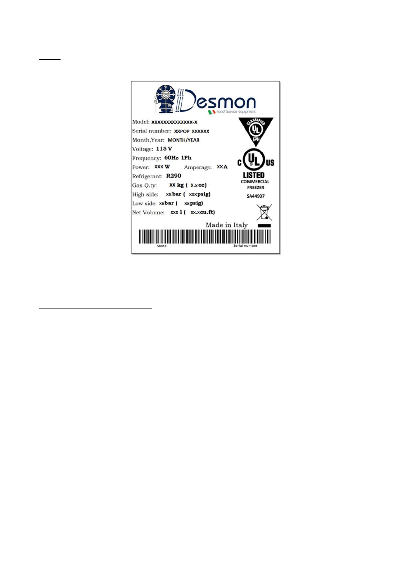
Note: All relevant data referring to these products can be found on the data label visible on the rear
part of the cabinet. Here is an example of the label:
How to read the Serial Number:
XX POP XXXXXX
Last two numbers of the production year
Progressive serial number of 6 numbers

STANDARDS AND GENERAL WARNINGS
6
Use and Operational Manual
1.1 TESTING AND INTENDED USE
This equipment is tested in compliance with established regulations and then shipped ready for use.
“If the equipment is used in a manner not specified by the manufacturer, the protection
provided by the equipment may be impaired.”
1.2 INTRODUCTION
This manual provides all instructions required for the correct use of the equipment and to keep it in
optimal condition. It also contains important user safety information. The following professional
roles are explained in order to define individual responsibilities:
Installer: a qualified technician who installs the equipment in accordance with these instructions.
User: the person who, after having read this manual carefully, uses the equipment in accordance
with the intended specification of use described in this manual. User’s responsibilities: ensure that
the product is kept at suitable temperatures in an ambient environment less than +40°C (104°F);
be aware of the regulations governing the conservation of products to refrigerate and to observe
any whatsoever hygiene indications that may be applicable. The user is obliged to carefully read
the manual and refer to its information at all times. Particular attention must be paid to safety
warnings (refer to Section 1.5).
Routine maintenance technician: qualified operator able to perform routine maintenance of the
equipment by following the instructions in this manual.
Service engineer: qualified technician, authorized by the manufacturer to perform extraordinary
maintenance of the equipment.
The symbol appears at certain points in the manual to draw the reader’s attention to important
safety information.
The manufacturer declines any responsibility in case of improper use of the equipment deviating
from the reasonably construed intended use, and for all operations carried out that are not in
compliance with the instructions reported in the manual.
This manual must be stored in an accessible and known place for all operators (installer, user,
routine maintenance technician, service engineer).
1.3 PRODUCT DESCRIPTION
The equipment comprises a single body with paneling in various materials and insulation with
expanded polyurethane foam. The equipment instruments are located on the front panel where the
electrical wiring is housed. The motor unit and the evaporator unit are housed on the top of body.
The interior parts are fitted with suitable supports for shelves. The doors are fitted with an automatic
return device and magnetic seal elements. During the design and construction stage all measures
have been adopted to implement total safety including radius interior corners, funnel-shaped base
panel to convey condensate to exterior, no rough surfaces, fixed guards protecting moving or
potentially dangerous parts.
1.4 CERTIFICATION
The appliances listed in this manual are manufactured in accordance with the following regulations:
- UL 60335-1: SAFETY OF HOUSEHOLD AND SIMILAR APPLIANCES- Part1: General
Requirements.
STANDARDS AND GENERAL WARNINGS
7
Use and Operational Manual
- UL 60335-2-89: HOUSEHOLD AND SIMILAR APPLIANCES - SAFETY - Part 2-89:
Particular Requirements for Commercial Refrigerating Appliances with an
Incorporated or Remote Refrigerant Unit or Compressor.
- NSF/ANSI7-2023 COMMERCIAL REFRIGERATORS AND FREEZERS.
1.5 GENERAL SAFETY REGULATIONS
Read this manual carefully and follow the instructions contained herein.
The user assumes full responsibility in case of operations carried out without observing the
instructions in the manual.
Do not use this product with flammable gases or flammable solvents.
Do not store flammable gases, flammable liquids or flammable solids in these units.
Primary general safety regulations:
Do not touch the unit with wet hands and/or feet. Do not use the equipment with bare feet;
Do not insert screwdrivers or other pointed objects between guards or moving parts of the
equipment;
Do not pull the power cord to disconnect the equipment from the electrical mains Make sure
that the equipment is not used by unsuitably qualified persons;
Before performing any cleaning or maintenance on the equipment disconnect it from the
electrical mains by switching off the main switch and extracting the plug;
Never use any metallic scouring pads, brushes, abrasive cleaners or strong alkaline
solution on any surface.
The relocation of the unit must be performed by qualified personnel. Do not shift the
refrigerator from side to side as this may create leakage point across the cooling unit piping.
In case of faults or malfunctions, switch off the equipment and do not attempt to repair it by
yourself as doing so may void the warranty. All service and repair operations must be
performed exclusively by a manufacture’s authorized engineer. (Authorized service
technician, trained service personnel, authorized service personnel)
Propane fridge/freezer, like any other appliance, must have access to fresh air/oxygen;
Keep clear of obstruction all ventilation openings in the appliance enclosure or in the structure
for building-in.
Do not use mechanical devices or other means to accelerate the defrosting process, other
than those recommended by the manufacturer.
WARNING: Do not damage the refrigerant circuit.
Do not use FLAME to check for gas leak.
Do not under any circumstances try to modify or repair valves, regulator, connectors,
controls or any other appliance. Doing so creates the risk of a gas leak.
1.6 CUSTOMER’S RESPONSIBILITIES
The customer is required to:
Execute the electrical connection of the equipment Prepare the place of installation;
Provide consumable materials for cleaning Perform routine maintenance;
In the case of power failures or malfunctions do not open the doors, in order to maintain the
internal temperature for as long as possible. If the problem persists for more than a few
hours, move the contents to a more suitable place.
STANDARDS AND GENERAL WARNINGS
8
Use and Operational Manual
1.7 CUSTOMER SERVICE REQUESTS
For all technical problems and any requests for technical service, refer exclusively to the
manufacturer’s authorized personnel;
1.8 ORDERING OF SPARE PARTS
Orders of spare parts should be made by consulting the part reference code and the serial
number of your unit. Consult your dealer.
1.9 PRODUCT CONFIGURATION
The unit is designed solely for products storage, which requires various controls and warning
in case of sudden alteration of temperature.
PRODUCTS MUST BE STORED IN ORDER TO ENSURE EFFICIENT AIR
CIRCULATION INSIDE THE UNIT AND SHALL NOT COME OUT OF THE SHELF
PERIMETER.
All uses outside of manufacturer’s intended use in section 1.1 shall be construed as “improper
use” for which the manufacturer declines all responsibility.
It’s allowed to accommodate on the shelf a maximum of 45 kg per shelf according to the
UL60335 regulation.
1.10 MATERIALS AND REFRIGERANTS
Materials in contact or potentially in contact with products are in compliance with the relevant
directives. The equipment designed and built so that contact parts can be cleaned before
each use. The refrigerants utilized comply with established regulations.
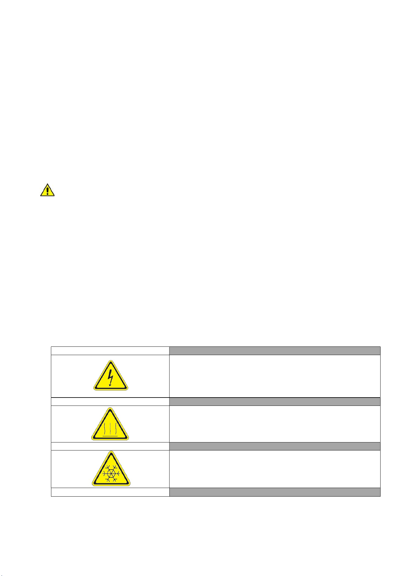
1.11 WARNING LABELS
Electrical Shock LABEL A
Use of this equipment involves power supplies which convert line
voltage to low voltage power. Do not modify or use power supplies
other than OEM equipment. Connection of the power supply may
require a properly grounded receptacle. Potential for electrical
shock or equipment damage exists if precautions are not followed.
Hot Surface LABEL B
Avoid contact with the hot surfaces potential for skin’s burns.
Cold Surface LABEL C
Avoid contact with cold freezer surfaces potential for cold burns or
skin sticking to cold surfaces.
Safety Alert LABEL D
STANDARDS AND GENERAL WARNINGS
9
Use and Operational Manual
Important operating instructions. To reduce the risk of injury or
poor performance of the unit read the user manual before putting
the equipment into operation.
Warning
Indicates an immediately hazardous situation, which if not avoided,
will result in death or serious injury.
Caution
Indicates an immediately hazardous situation, which if not avoided,
may result in minor to moderate injury
Battery
LABEL E
Indicates the location of the back-up battery
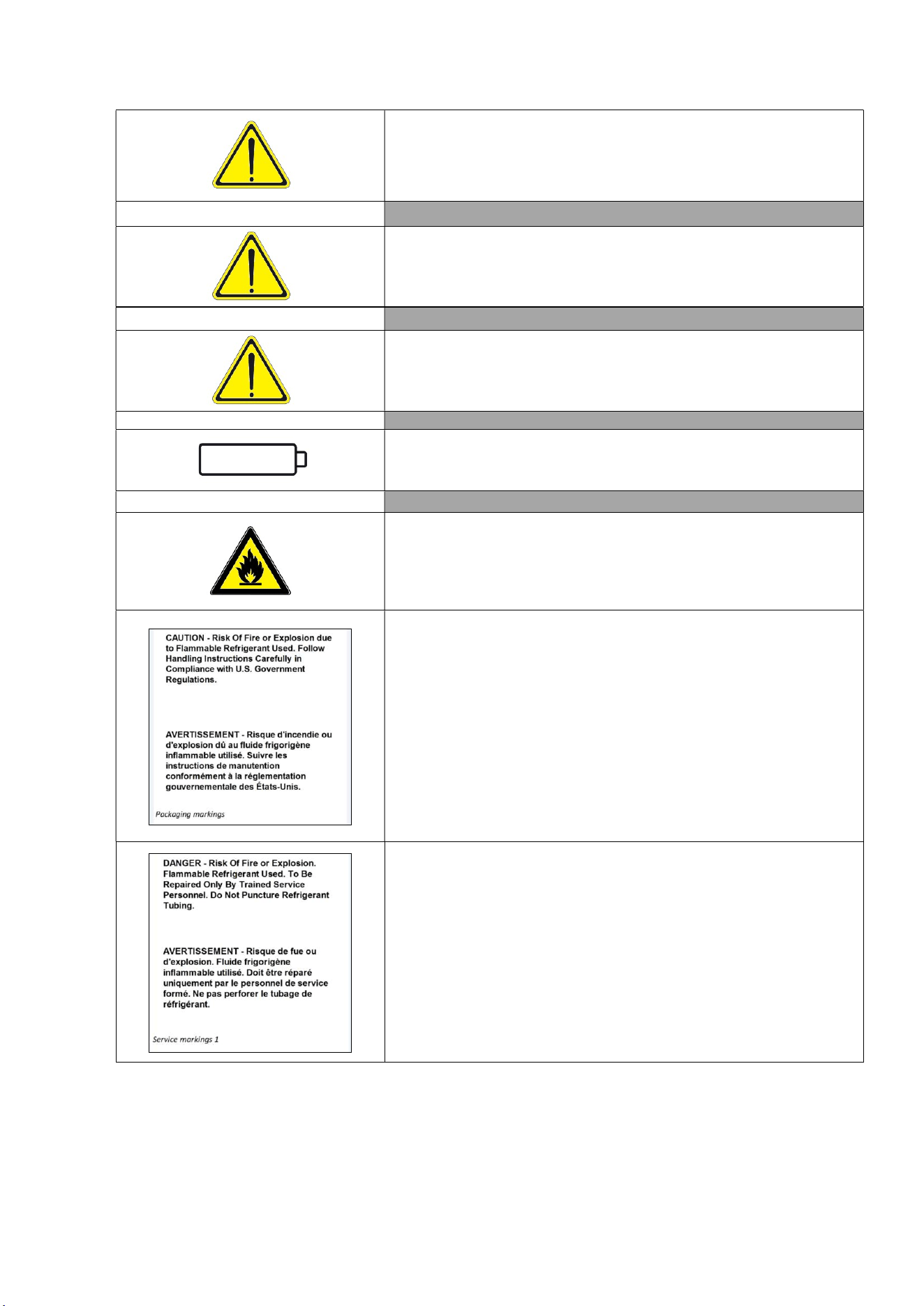
Risk of fire LABEL F
Risk of fire or explosion. Flammable refrigerant used. Follow
handling instruction carefully. To be repaired only by trained
service Personnel. Do not puncture Refrigerant Tubing.
Packaging markings
(Label attached upon the cartoon box)
Service markings.
(Label located near the cooling unit compartment)
STANDARDS AND GENERAL WARNINGS
10
Use and Operational Manual
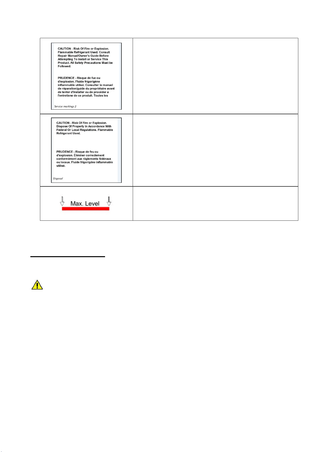
Service markings
(Label located near the cooling unit compartment)
Disposal
(Marking attached upon the exterior of the cabinet)
Max high load
2. INSTALLATION
2.1 TRANSPORTATION AND HANDLING
The equipment must be transported and handled exclusively in upright position, in
observance of the instructions printed on the packing.
This precaution is necessary to avoid contamination of the refrigerant circuit with compressor lube
oil with resulting valve and heat exchanger coil failure and problems starting the electric motor or the
risk of a gas leak. The manufacturer is not responsible for any problems due to transport executed
in conditions other than those specified herewith.
The equipment is secured to a wooden pallet base, wrapped in a plastic film and packaged into a
three waves carton box..
The equipment must be handled using a fork lift truck or a pallet truck with suitable forks (fork length
at least equal to 2/3 length of unit).
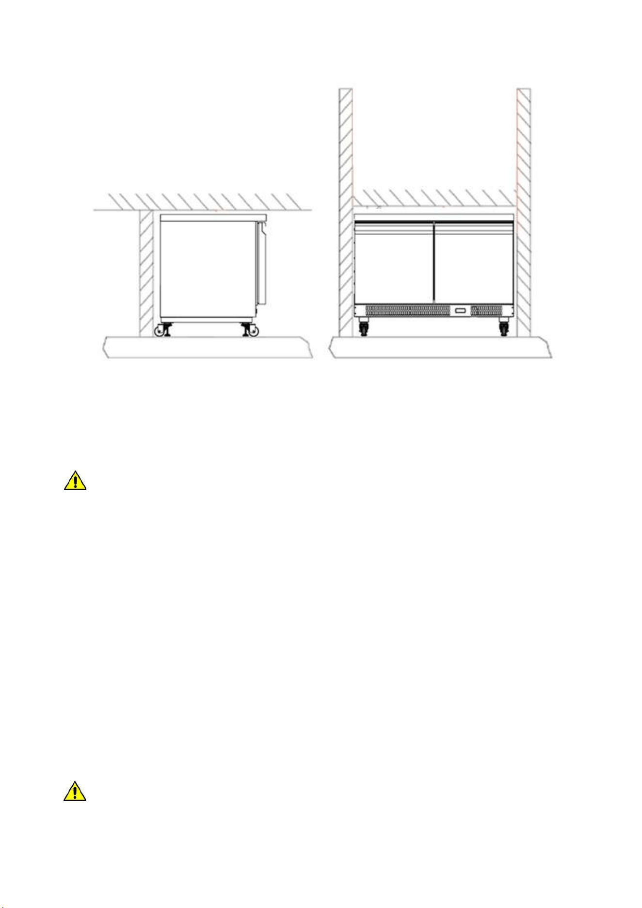
2.2 POSITIONING
Incorrect positioning can cause damage to the equipment and generate hazardous conditions for
personnel. The installer must therefore observe the following general regulations:
The unit can be recessed into a wall. No specific clearance are required. The room must be well
ventilated.
INSTALLATION
11
Use and Operational Manual
Keep well away from sources of heat. Avoid direct sunlight.
Remove packing material.
Remove accessories from inside the unit.
Cartoon box or Wood base removal: using a hammer, tilt the cabinet to one side and loosen the
two thread-forming screws, drag the cabinet from the back side holding the base still until the
four castors have gone out from the containing holes, slightly tilt the cabinet backward and take
the base away pulling it from the front side.
Use gloves when handling the 3 Waves cartoon box or the wooden base to protect the hands
from splinters.
Position the equipment with the help of a level. Remove the protective PVC film from the external
surfaces of the unit.
Position the shelf runners in the holes in the uprights. Insert the shelves in the runners.
Note: the shelves included are n.01 per each door.
The maximum load of each is 48 kg.
2.3 WIRING AND ELECTRICAL HOOK-UP
Receptacle installation and electrical wiring operations must be performed by a qualified electrician.
For safety reasons adhere to the following indications:
Check that the electrical plant is suitably sized for the absorbed power of the unit.
If the electrical socket and the plug on the equipment power cord are incompatible, call
technical service or your local distributor.
The power cord set included with the appliance meets the requirements for use in the
country of purchase. Use the power cord that shipped with the appliance (Nema 5-15).
If this appliance is to be used in another country, purchase an AC power cord set that
is approved for use in that country.
The power cord must be rated for the product and for the voltage and current marked
on the product's electrical ratings label. The voltage and current rating of the cord
should be greater than the voltage and current rating marked on the product.
INSTALLATION
12
Use and Operational Manual
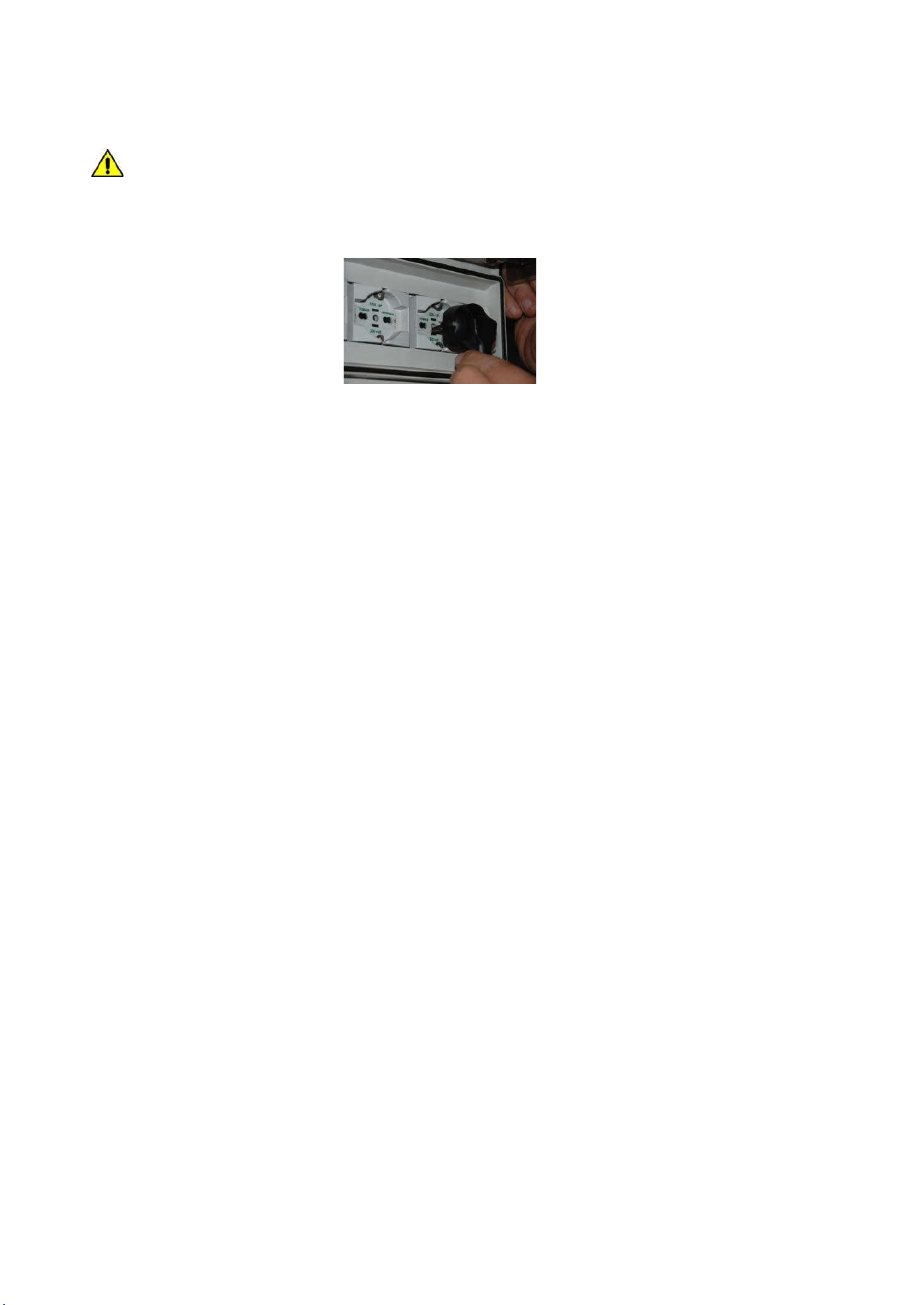
Do not use reductions or multi-way adapters (Fig.1)
It is important to connect the equipment correctly to an efficient earth system executed
in compliance with the relevant legislation.
The equipment must be positioned so that plug can be easily reached (Fig. 1)
Fig. 1
If the SUPPLY CORD is damaged, it must be replaced by the manufacturer, its service agent
or similarly qualified persons in order to avoid a hazard.
2.4 SET UP OPERATIONS
To avoid errors and accidents, perform a series of checks for possible damage sustained during
transport, installation and hook-up operations before starting up the unit.
PRELIMINARY CHECKS
Check the condition of the power cord (no cut or chaffing). Check that the door hinges and shelf
support are stable.
Check the door seals and shelves are not damaged (broken or scratched) and that the door
closes and seals properly.
Make sure all copper tubing, unions are in perfect condition.
FOR OPTIMAL PERFORMANCE
Do not block the motor compartment air vents.Before storing products wait until they are cold.
Arrange the products on suitable shelves or in containers. Do not place products directly on the
base or against the walls, doors, or fixed guards of the unit.
Make sure doors are kept closed.
Keep the defrost water drain outlet clear.
Limit the frequency and duration of opening; each time the door is opened the internal
temperature will alter.
Load products at ambient temperature gradually to allow correct refrigeration. Perform routine
maintenance regularly.
2.5 RE- INSTALLATION
Observe the following procedure:
Disconnect the power cord from the electrical outlet.
Handle the equipment in accordance with the instructions in Section 2.1.
Follow the instructions in Section 2.2 for positioning and hook-ups in the new location.
2.6 SCRAPPING AND DISPOSAL
These units may contain materials, which at the end of the working life of the apparatus, must be
disposed at one of the recycling centers nominated by your Local National Health Department or as
INSTALLATION
13
Use and Operational Manual
specified by the law in force. Scrapping and disposal of the equipment must be carried out in full
observance of established legislation in your country.
In particular, the apparatus may contain the following materials:
Iron
Copper
Aluminium
Non-biodegradable plastics
Fibre glass for printed circuits
Ferrite
Batteries
CFC-free refrigeration gas
Electrical and electronic equipment (WEEE)
The manufacturer shall not be chargeable for any disposal of the apparatus at the end of its
working life.
In line with EU Directive 2002/96/EC for waste electrical and electronic equipment
(WEEE), this electrical product must not be disposed of as unsorted municipal waste.
Please dispose of this product by returning it to your local municipal collection point for
recycling.
3. OPERATION
Before switching ON the unit, check that the electrical connections have been made correctly and
above all, that the ground connection is available and working properly.
Please read before using this manual
- This manual is part of the product and should be kept near the instrument for easy and quick
reference.
- Digital controller with defrost and fans management shall not be used for purpose different
from those described hereunder. It cannot be used as a safely device.
- Check the application limits before proceeding.
Safety precautions
- Check the supply voltage is correct before connecting the instrument.
- Do not expose to water or moisture: use the controller only within the operating limits avoiding
the temperature changes with high atmospheric humidity to prevent formation of
condensation.
Warning
- Disconnect all the electrical connections before any kind of maintenance.
- In case of failure or faulty operation contact technical service or Dealer.
- Consider the maximum current which can be applied to each relay.
- Ensure that the wired for probes, loads and the power supply are separated and far enough
from each other, without crossing or intertwining.
3.1 EWP974 EO CONTROLLER GENERAL DESCRIPTION
The controller is a microprocessor-based controller suitable for normal and low temperature air-
ventilated application.

OPERATION
14
Use and Operational Manual
It has dimensions 74 x 32 x 59 mm, snap-in bracket to be fitted on the panel, four electro-mechanical
relays to control the compressor, defrost hot gas valve, evaporator fan and an auxiliary relay
used as a dry contact.
The controller is also provided with 2 probe inputs either NTC type: the probe “Pb1” defined as
“Control probe” and used for the compressor activation, the “Pb2” defined as “Evaporator probe”
and used to control the evaporator fan operation and the defrost cycle; The device has also an
additional input configurable as analogue input (“Auxiliary probe” Pb3) or digital input (“Door
switch/multi-function input”)
Technical Data
Case: Black color, self-extinguishing.
Heat and fire resistance category: D.
Connections: Fixed screws terminal blocks for wires up to 2,5 mm
2
; removable screw terminal
blocks for wires up to 2,5 mm
2
(by request); Micro-MaTch connectors.
Maximum length allowed to the connection cables: 10 meters (32,8ft) for power supply cord;
10 meters (32,8ft) for Analogue inputs; 10 meters (32,8ft) for Digital inputs; 10 meters (32,8ft)
for Digital outputs.
Operating temperature: from -5°C to 55°C (from 23 to 131°F)
Operating humidity: Relative humidity without condensate from 10 to 90%.
Pollution status of the device: 2.
Power supply: 230VA (±10%) 50/60 Hz
Over voltage category: II.
Analogue input: 2 for NTC/PTC nodes (Cabinet probe and Evaporator probe)
Sensor range: NTC: from -50°C to 110°C (from -58 to 230°F)
Sensitivity: 0,1°C (1°F)
Digital inputs: 1 (microport) for NO/NC contact
Terminals: screw/disconnectable terminals for cables with a diameter of 2.5mm2
Connectors: TTL for connection of Copy Card + D.I.2
Digital outputs: 3 electro-mechanical relays
Compressor relay:12A res. @250VCA (NO contact)
Evaporator fan relay: 8A res @250VCA(NO contact) - 6A res @250VCA(NC contact)
Auxiliary relay: 5A res @250VCA
Alarm buzzer: Incorporated.
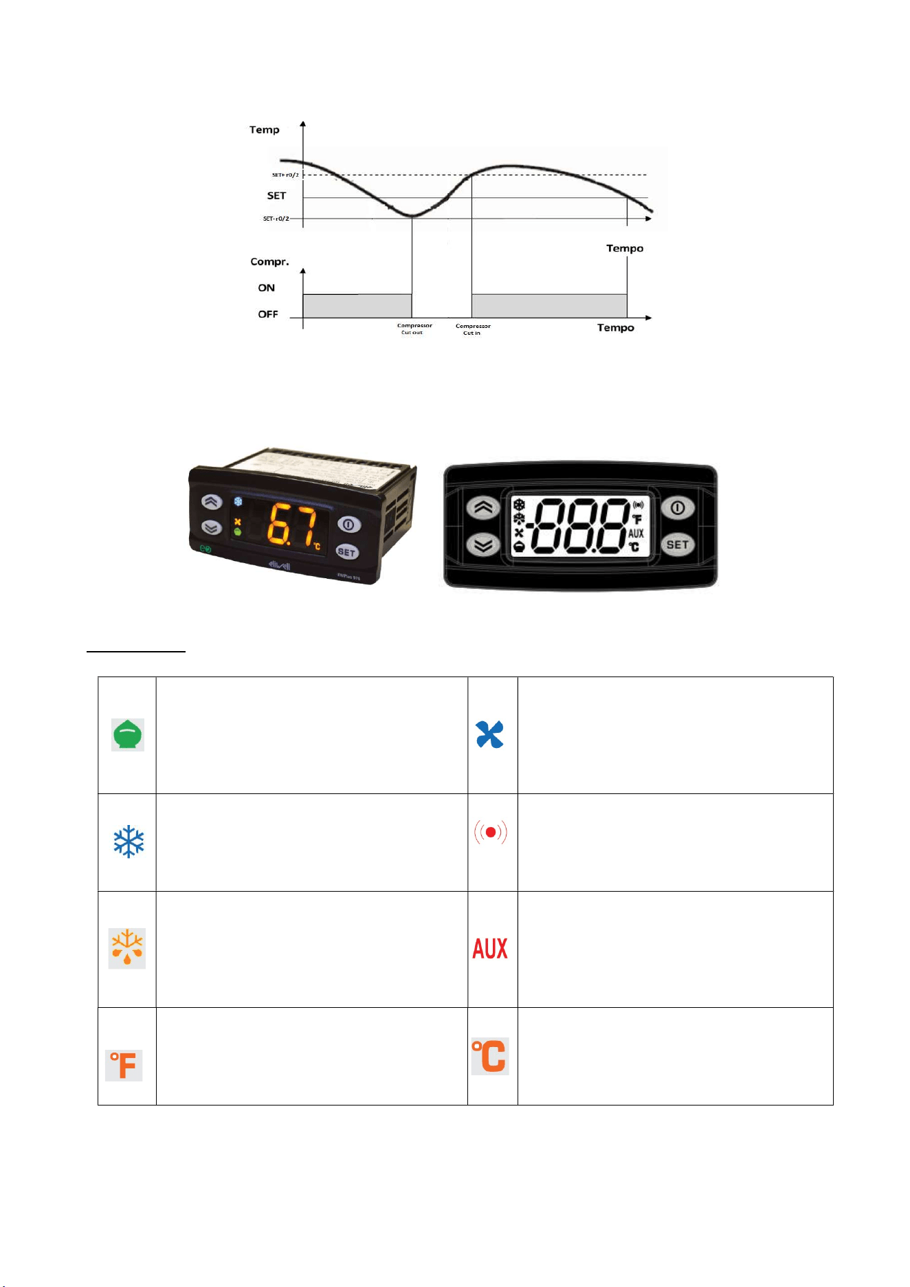
3.1.1 REGULATION
Once set a desired temperature required for the products storage within the operational range of
each models, the regulation of the cooling system is controlled by the temperature measured by
the control probe with a positive differential from the set point: when the temperature rises up to
the set point plus differential the compressor starts to pull down the temperature and it turns off
when the desired set point is reached again.
In case of faulty probe, the compressor activation is timed through the parameter “Ont” and “OFt”
OPERATION
15
Use and Operational Manual
3.1.2 CONTROLLER USER INTERFACE AND MAIN FUNCTION
Use of LEDs
Reduced Set/Economy Set
Permanently ON: Energy Saving ON
Blinking: Reduced set point active
Rapid blinking: access to level 2
password
OFF:
Otherwise
Fan LED
Permanently ON: Fan active
OFF: Otherwise
Compressor LED
Permanently ON: Compressor active
Blinking: delay, protection or start-up
blocked
OFF: Otherwise
Alarm LED
Permanently ON: alarm present
Blinking: Alarm acknowledged
OFF: Otherwise
Defrost LED
Permanently ON: defrost active
Blinking: activated manually or by
digital input
OFF: Otherwise
Auxiliary input LED
Permanently ON: Aux output active
Blinking: deep cooling cycle active
OFF: Otherwise
°F readout LED
Permanently ON: °F reading active
(dro=1)
OFF: Otherwise
°C readout LED
Permanently ON: °C reading active
(dro=0)
OFF: Otherwise
OPERATION
16
Use and Operational Manual
Use of Keys
No.
Key Action pressing and release Action pressing for at least 5 secs.
1
- Scrolls through menu items
- Increases values
- Activates the Manual Defrost function
(when outside the menus)
2
- Scrolls through menu items
- Decreases values
-No use.
3
- Returns to the previous menu level
- Confirms parameter value
- Activates the Standby function (when
outside the menus)
4
- Displays any alarms (if active)
- Opens Machine Status menu
- Opens Programming menu (User and
Installer Parameters)
- Confirms commands
3.1.3 Switching the device ON/OFF
The instrument can be switched off/on by pressing the key for longer than 5 seconds.
Switching off the device, the adjustment algorithms and defrost cycles are disabled and the text
“OFF” will appear on the display. Once the device is switched on the display will show the actual
air temperature read by the air probe.
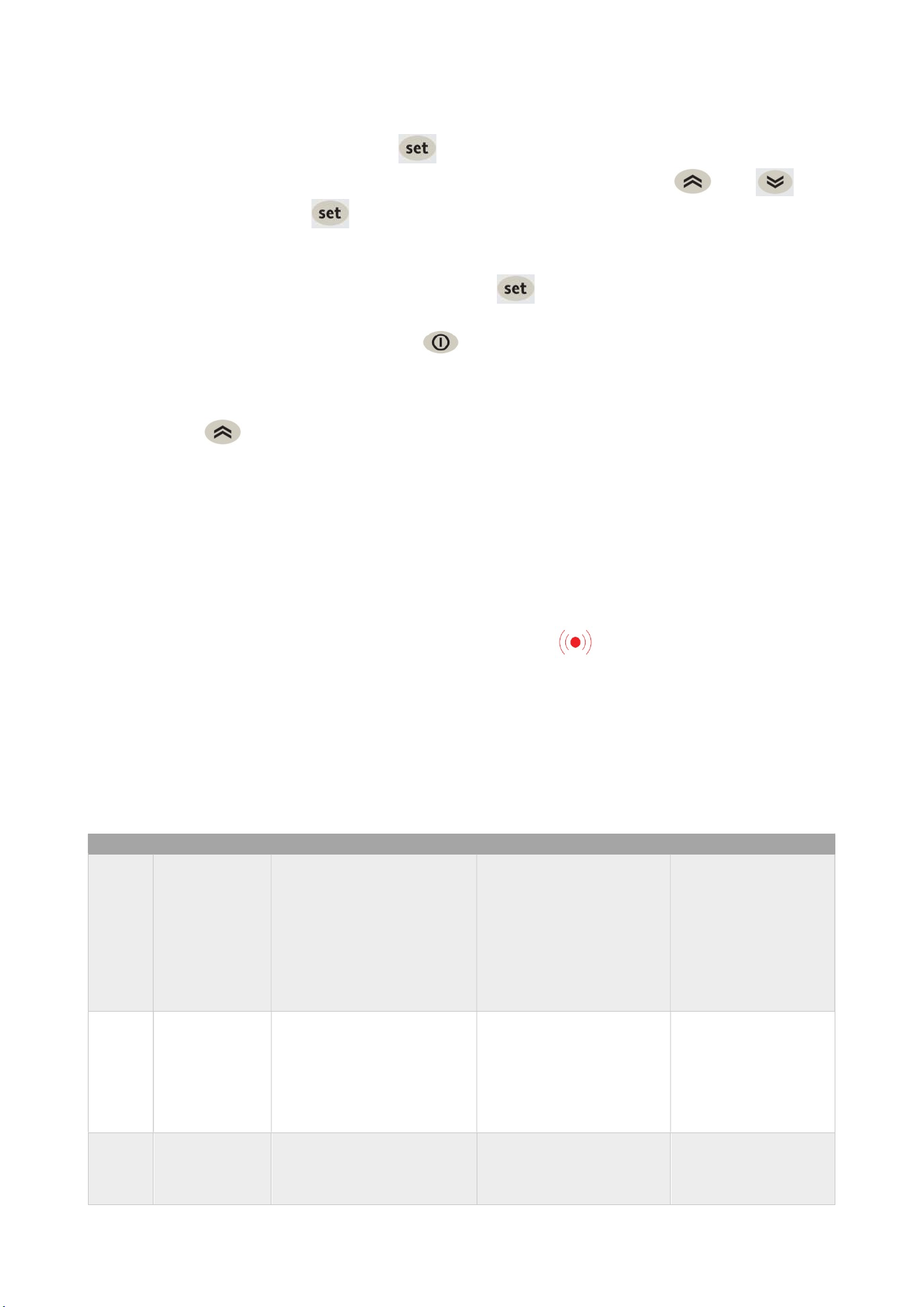
3.1.4 “MACHINE STATUS" MENU
Access the Machine Status menu by pressing and releasing the key. If no alarms are active,
the “SEt” label appears.
Use the keys and to scroll through all the folders in the menu:
AL: alarms folder (only visible if an alarm is active)
SEt: Setpoint setting folder
Pb1: Air probe
Pb2: Evaporator probe (if H42=y)
Pb3: Condenser probe (only if H11=0 and H43=y)
OPERATION
17
Use and Operational Manual
SETPOINT SETTING:
To display the Setpoint value press the key when the “SEt” label is displayed. The Setpoint
value appears on the display. To change the Setpoint value, press the and keys
within 15 seconds. Press to confirm the modification.
DISPLAYING THE PROBES
When labels Pb1, Pb2 or Pb3 are present, press the key to view the value measured by the
corresponding probe.
To quit the Machine status menu, press the key and release.
3.1.5 MANUAL DEFROST CYCLE ACTIVATION
Hold down the key for longer than 5 seconds. It is only activates if the temperature conditions
are fulfilled. Otherwise, the display will flash three times to indicate that the operation will not be
performed.
Propane unit performs a hot gas defrost: when the defrost cycle is active a solenoid valve opens and
the compressor runs to by-pass the hot gas from the discharge line into the evaporator coil. The
defrost cycle ends when the evaporator reaches the dSt temperature or the dEt time is elapsed.
3.1.6 DIAGNOSTICS
Alarms are always indicated by the buzzer and the alarm icon .
To switch off the buzzer, press and release any key; the corresponding icon will continue to flash.
Note that if alarm exclusion times have been set the alarm will not be signaled.
- E1: In the event of cold room probe faulty (Pb1), the indication “E1” will appear on the display.
- E2: In the event of defrost probe faulty (Pb2), the indication “E2” will appear on the display
3.1.7ALARMS
Label
Fault
Cause
Effects
Remedy
E1
Probe1 faulty
(cold room)
-measured values are
outside operating range
-Probe faulty/short-
circuited/open
-Display label E1
-Alarm icon permanently
on
-Disable max/min alarm
controller
-Compressor operation
based on parameters
“Ont” and “OFt”
-check probe type
-check probe wiring
-replace probe
E2
Probe2 faulty
(defrost)
-measured values are
outside operating range
-Probe faulty/short-
circuited/open
-Display label E2 Alarm
icon permanently on
-The Defrost cycle will
end due to Timeout
-The evaporator fans will
work in Duty Cycle mode.
-check probe type
-check probe wiring
-replace probe
E3
Probe3 faulty
(if enable)
-measured values are
outside operating range
-Probe faulty/short-
circuited/open
-Display label E3:Alarm
icon permanently on
-check probe type
-check probe wiring
-replace probe

OPERATION
18
Use and Operational Manual
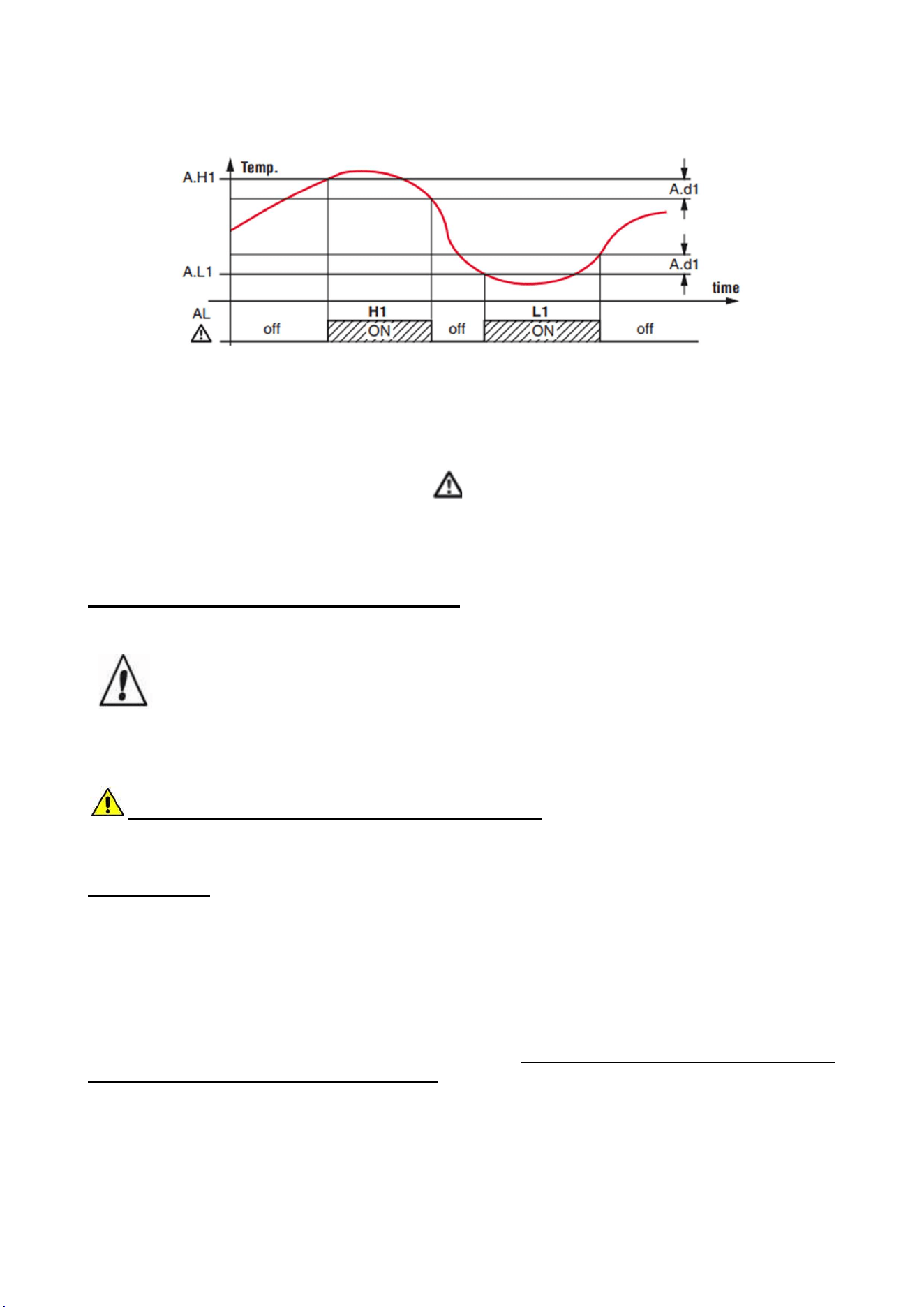
AH1
Alarm for
HIGH
Pb1
temperature
value read by Pb1 >HAL
after time of tAO. (see
“MAX/MIN
TEMPERATURE
ALARMs")
-Recording of label AH1
in folder AL
-No effect on regulation
-Wait until value read
by Pb1 returns below
HAL-Afd
AL1
Alarm for
LOW
Pb1
temperature
value read by Pb1 <LAL
after time of tAO. (see
“MAX/MIN
TEMPERATURE
ALARMs")
-Recording of label AL1
in folder AL
-No effect on regulation
-Wait until value read
by Pb1 returns above
LAL+Afd
EA
External alarm
digital input activation
(H11 = ±5)
-Recording of label EA in
folder AL
-Alarm icon permanently
on
-Regulation locked if rLO
= y
-check and remove
the external cause
which triggered the
alarm on the D.I.
OPd
Door open
alarm
digital input activation
(H11 = ±4)
(for longer than tdO)
-Recording of label Opd
in folder AL
-Alarm icon permanently
on
-Controller locked
-close the door
Ad2
end of defrost
cycle due to
timeout
end of defrost cycle due to
timeout rather than due to
defrost end temperature
being recorded by probe
Pb2
-Recording of label Ad2
in folder AL
-Alarm icon permanently
on
-wait for the next
defrost cycle for
automatic return
Ad3
end of defrost
cycle due to
timeout
activation of the defrost for
temperature
independently dAt. (active
if dCt = 3)
-Recording of label Ad3
in folder AL
-Alarm icon permanently
on
-wait for the next
defrost cycle for
automatic return
COH
Over Heating
alarm
Pb3 value set by
parameter SA3 exceeded.
-Display label COH
-Alarm icon permanently
on
-Regulation locked
(Compressor)
-wait for the
temperature to return
to a value of SA3
(Setpoint) minus dA3
(differential).
nPA
General
pressure
switch alarm
Activation of pressure
alarm by general pressure
switch.(H11 = ±7)
-If the number N of
pressure switch
activations isN<PEn:
-Recording of folder nPA
in folder AL, with the
number of pressure
switch activations
-Regulation locked
(Compressor and Fans)
-check and remove
the cause which
triggered the alarm
on the D.I.
(Automatic Reset)
PAL
General
pressure
switch alarm
Activation of pressure
alarm by general
pressure switch.
(H11 = ±7)
-If the number N of
pressure switch
activations is
N=PEn:
-Display label PAL
-Recording of label PA in
folder AL
-Alarm icon permanently
on
-Regulation locked
(Compressor and Fans)
-Switch the device off
and back on again
-Reset alarms by
entering the
functions folder and
selecting the rAP
function (Manual
Reset)
OPERATION
19
Use and Operational Manual
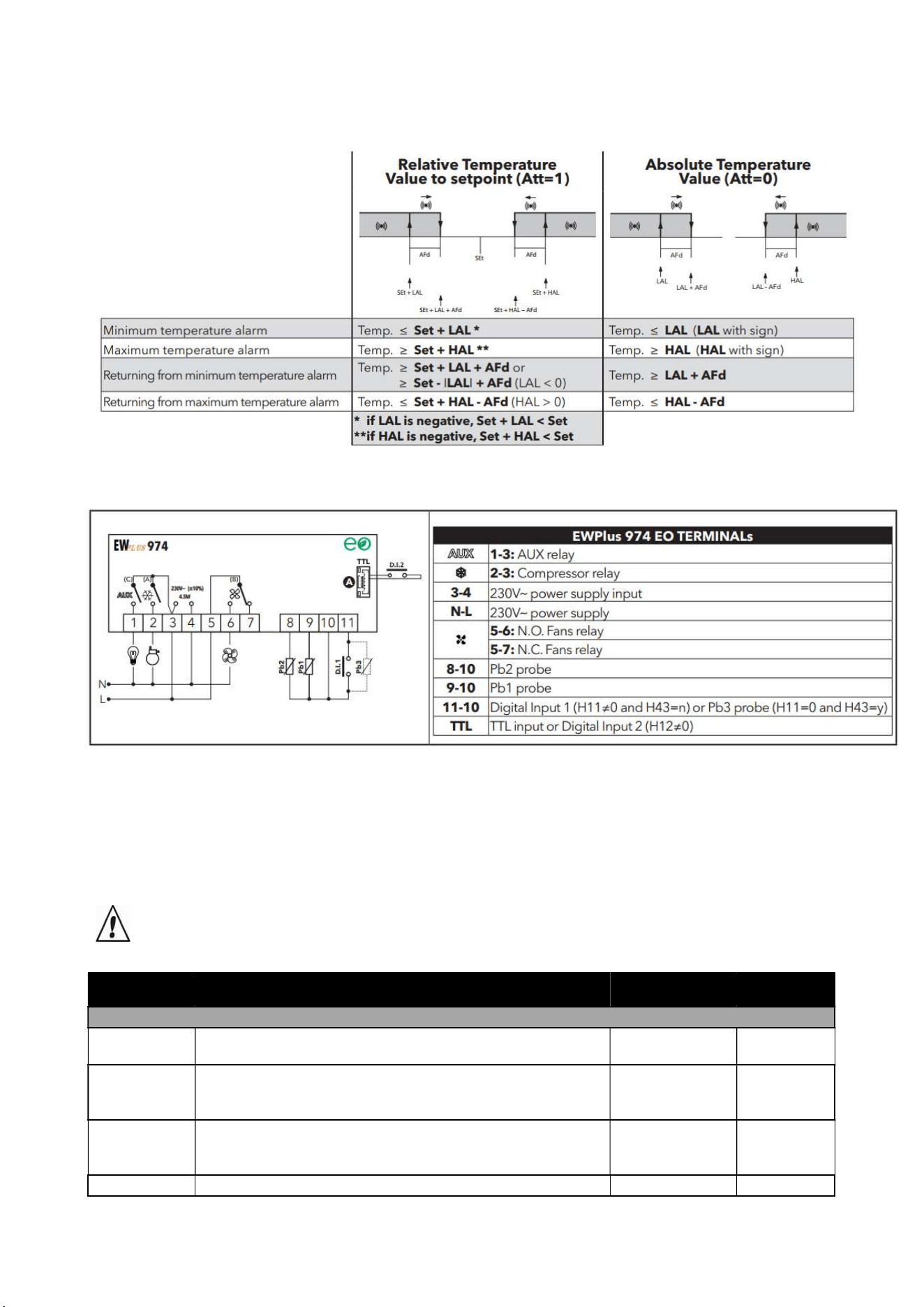
MAX/MIN TEMPERATURE ALARMs
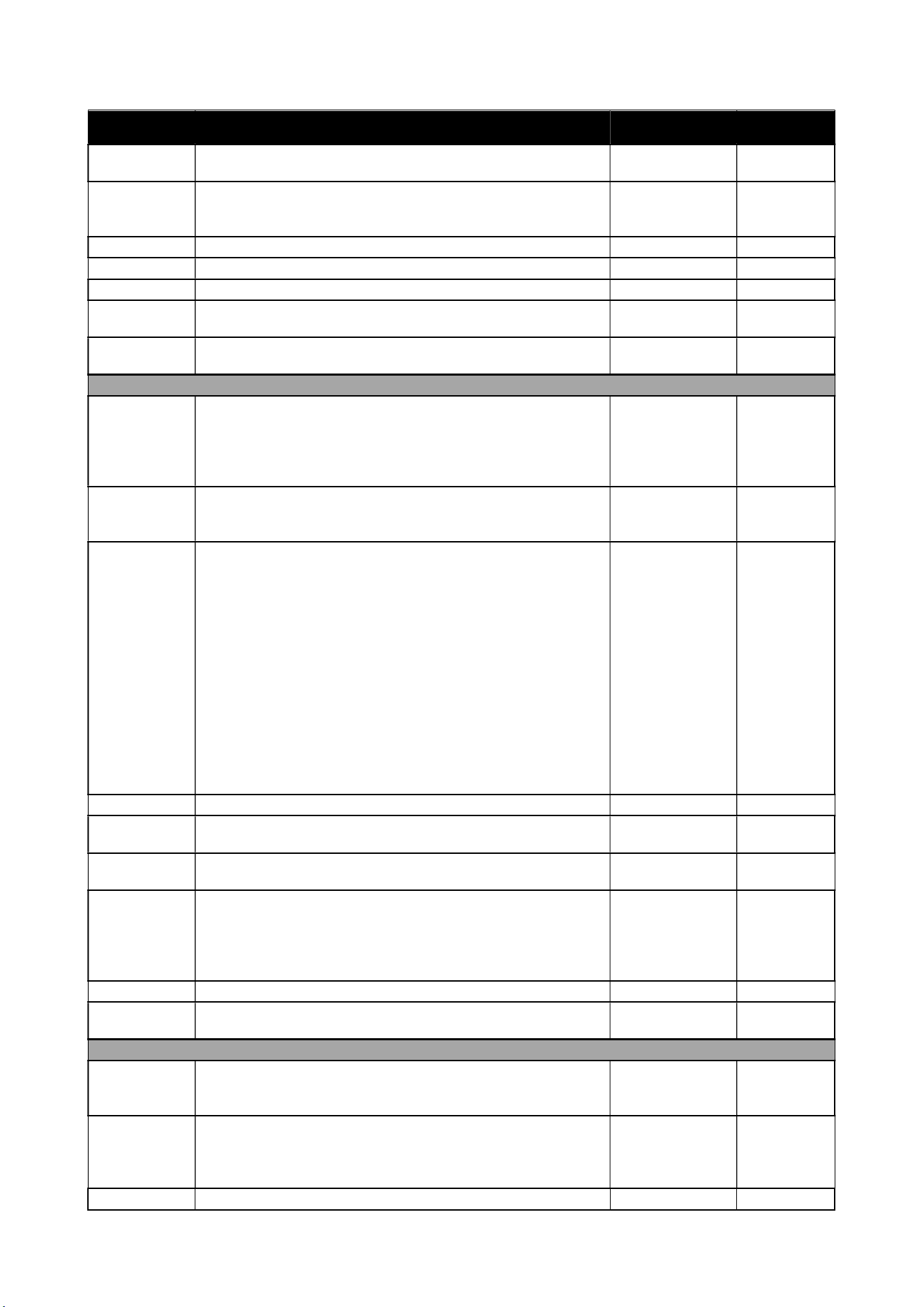
3.1.8 CONTROLLER’S INPUT/OUTPUT
3.1.9 PARAMETERS LIST DESCRIPTION
All parameters necessary for the correct operation of the machine have already been programmed
into the control panel. In the event that it becomes necessary to vary some of these parameters,
please contact the manufacturer or the authorized service agent.
CAUTION! The modification of a level 2-parameter without authorization of the manufacturer
causes the loss of guarantee.
Parameter Description Range Unit of M.
Compressor parameters (
CP
folder)
diF
Differential: Compressor relay activation differential. N.B.:
diF cannot be equal to 0.
0,1 …. 30,0 °C/°F
HSE
Maximum value that can be assigned to the Setpoint.
N.B.: The two Setpoints are interdependent: HSE
cannot be less than LSE and vice
-
versa.
LSE ... 320 °C/°F
LSE
Minimum value that can be assigned to the Setpoint.
N.B.: The two Setpoints are interdependent: LSE
cannot be higher than HSE and vice
-
versa.
-67,0 ... HSE °C/°F
Ont
Controller on time for faulty probe. 0 ... 250 Min
OPERATION
20
Use and Operational Manual
Parameter Description Range Unit of M.
- if Ont = 1 and OFt = 0, the compressor remains ON,
- if
Ont
> 0 and
OFt
> 0, it runs in duty cycle mode.
OFt
Controller off time for faulty probe.
- if OFt = 1 and Ont = 0, the compressor remains OFF,
- if
Ont
> 0 and
OFt
> 0, it runs in duty cycle mode.
0 ... 250 Min
dOn
Compressor relay activation delay after request. 0 ... 250 Secs
dOF
Delay after switching off and subsequent activation. 0 ... 250 Min
dbi
Delay between two consecutive compressor activations. 0 ... 250 Min
OdO
Delay in activating outputs after the instrument is switched
on or after a power failure.
0 = not active
0 ... 250 Min
dFA
Delay time in activating compressor and condenser fans
after request
0 … 255 Secs
Defrost parameters (
DEF
folder)
dty
Type of defrost.
0= electric defrost - compressor OFF during defrost cycle
1= cycle inversion defrost (hot gas) - compressor ON
during defrost cycle
2= ‘Free’: defrosting independently of compressor
0/1/2 Num
dit
Interval between the start of two consecutive defrost
cycles.
0 = function disabled
(defrosting NEVER performed)
0 … 250 Hours
dCt
Selects the count mode for the defrost interval:
-0 = compressor hours of operation (DIGIFROST®
method); Defrost active ONLY when the compressor is on.
N.B.: compressor operation time is counted separately
from the evaporator probe (count active also when
evaporator probe missing or faulty).
-1 = appliance running hours = the defrost count is always
active when the machine is on and starts at each power-
on;
-2 = compressor stop Every time the compressor stops, a
defrost cycle is performed according to parameter dtY;
-3 = temperature
0/1/2/3 Num
dOH
Defrost start delay time after request. 0 .. 59 Min
dEt
Defrost time-out; determines the maximum defrost
duration.
1 .. 250 Min
dSt
Defrost end temperature (determined by the evaporator
probe).
-67,0 ... 320 °C/°F
dPO
Determines whether the instrument must enter defrost
mode (if the temperature measured by the evaporator
allows this operation).
-n = no, does not start defrosting at start-up;
-y = yes, starts defrost at start-up.
n/y Flag
dSE
Temperature threshold for start of defrost -67.0 .. 320 °C/°F
dtt
Time for which the temperature of the evaporator must
remain below dSE
0 .. 250 Min
Fan regulator parameters (
FAn
folder)
FPt
Characterizes the "FSt" parameter that can be expressed
or as an absolute temperature value or as a value related
to Setpoint.
0
= absolute;
1
= relative
0/1 Flag
FSt
Fan lock temperature: if Pb2 > FSt, the fans are stopped.
The value is either positive or negative and, depending on
parameter FPt, can be either the absolute temperature or
the temperature relative to the Setpoint
-67,0 ... 320 °C/°F
FAd
Fan starting differential (see parameters FSt and Fot). 1,0 ... 50,0 °C/°F
OPERATION
21
Use and Operational Manual
Parameter Description Range Unit of M.
Fdt
Delay time in activating fans after a defrost operation. 0 ... 250 Min
dt
drainage time. Dripping time. 0 ... 250 Min
dFd
Allows to select the evaporator fans exclusion during
defrost.
y
= yes;
n
= no.
n/y Flag
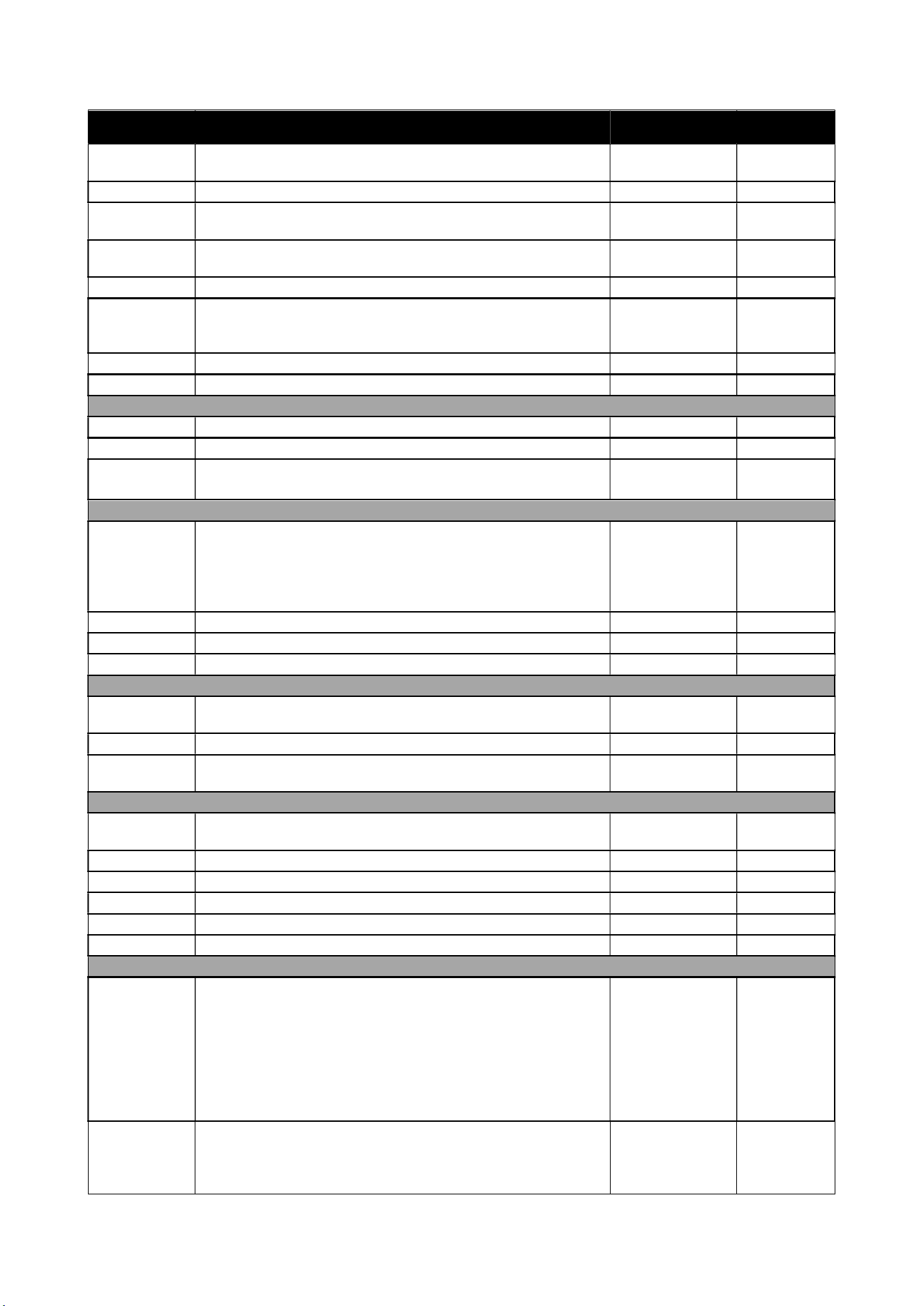
FCO
Evaporator fans operating mode. The state of the fans will
be:
Dutycycle Day: controlled by means of parameters “Fon”
and “FoF”.
Dutycycle Night: controlled by means of parameters
“
Fnn
” and “
FnF
”
0/1/2/3 Num
FdC
Evaporator fans switch-off delay after compressor disabled
0 .. 99 Min
Fon
Fans ON time in duty cycle. Fans used in duty cycle mode;
valid when
FCO = dc
and
H42=1
(Pb2 probe present)
0 .. 250 secs*10
FoF
Fans OFF time in duty cycle. Fans used in duty cycle
mode; valid when FCO = dc and H42=1 (Pb2 probe
present)
0 .. 250 secs*10
Fnn
Fans ON time in night duty cycle. Fans used in duty cycle
mode; valid when FCO = dc and H42=1 (Pb2 probe
present)
0 .. 250 secs*10
FnF
Fans OFF time in night duty cycle. Fans used in duty cycle
mode; valid when FCO = dc and H42=1 (Pb2 probe
present)
0 .. 250 secs*10
Alarms parameters (
AL
folder)
Att
Parameters HAL and LAL intended as the absolute
temperature value or differential in relation to the setpoint.
0 = absolute value; 1 = relative value.
N.B.: In case of relative values (para. Att=1) parameter
HAL should be set to positive values, whilst parameter
LAL should have only negative values (
-
LAL).
0/1 Num
AFd
Alarm differential. 1,0 .. 50,0 °C/°F
HAL (!)
Maximum temperature alarm. Temperature value
(intended either as distance from Setpoint or as an
absolute value based on Att) which, if exceeded in an
upward direction, triggers the activation of the alarm
signal.See
"Max/Min Temperature Alarms".
LAL to 320 °C/°F
LAL (!)
Minimum temperature alarm. Temperature value (intended
as distance from the set point or as an absolute value
based on Att) which, when exceeded downwards, triggers
the activation of the alarm signal.See "Max/Min
Temperature Alarms".
-67,0 to HAL °C/°F
PAO (!)
Alarm exclusion time after instrument switch on, after a
power failure.
This parameter refers to high/low temperature alarms
only.
0 .. 10 Hours
dAO
Temperature alarm exclusion time after defrost. 0 .. 999 Min
OPERATION
22
Use and Operational Manual
Parameter Description Range Unit of M.
OAO
Alarm signaling delay (low and high temperature) after
digital input disabling (door close).
0 .. 10 Hours
tdO
Alarm activation delay time open door. 0 .. 250 Min
tAO
Temperature alarm signal delay time.
This parameter refers to high/low temperature alarms only.
0 .. 250 Min
dAt
Alarm for defrosting ended due to time out.
n
= alarm deactivated;
y
= alarm activated
n/y flag
rLO
External alarm locks controllers. n = does not lock; y=locks
n/y Flag
AOP
Alarm output polarity.
0 = alarm active and output disabled; 1 = alarm active and
output enabled.
0/1 Num
SA3
Probe Pb3 Alarm Setpoint. -67,0 ... 320 °C/°F
dA3
Probe Pb3 alarm activation differentia 1,0 ... 50,0 °C/°F
Cool protection parameters (
CPr
folder)
CPS
Cool protection setpoint -67,0 ... 320 °C/°F
CPd
Cool protection differential 0,1 ... 30,0 °C/°F
CPt Time that the temperature remains below the cool
protection Setpoint (
CPS
)
0 ... 255 Min
LIGHTS & DIGITAL INPUTS parameters(
Lit
folder)
dOd
Enable utility switch-off on activation of door switch.
-0 = disabled
-1 = disables fans
-2 = disables the compressor
-
3
= disables fans and compressor
0/1/2/3 Num
dAd
Activation delay for digital input 0 ... 255 Min
dCO
Compressor deactivation delay after door opened 0 ... 255 Min
dCd
Fans activation delay after door closed 0 ... 250 Secs
PRESSURE SWITCH parameters(
PrE
folder)
PEn
Number of errors allowed for general pressure switch
input.
0
= disabled
0 ... 15 Num
PEI
Minimum/maximum pressure switch error count interval 1 ... 99 Min
PEt
Delay in activating compressor after pressure switch
deactivation
0 ... 255 Min
DEEP COOLING parameters(
dEC
folder)
dCA
Enable deep cooling (0 = disabled; 1 = manual; 2 =
automatic).
0/1/2 Num
dCS
Deep cooling setpoint -67,0 ... 320 °C/°F
tdC
Deep cooling duration 0 ... 255 Min
dcc
Defrost delay after deep cooling 0 ... 255 Min
Sid
Deep cooling start threshold -67,0 ... 320 °C/°F
toS
Over-threshold time for deep cooling start 0 ... 255 Min
ENERGY SAVING parameters (
EnS
folder)
ESt
Energy Saving mode:
-0= disabled;
-1= Offset on setpoint;
-2= Offset on differential;
-3= Offset on setpoint and differential;
-4= Bottle cooler open front' algorithm;
-5= Bottle cooler glass door' algorithm;
-
6
= Vertical display cabinet' algorithm
0 ... 6 Num
ESA
AUX output status in energy saving mode:
-0 = disabled (no effect on AUX);
-1 = AUX off;
-
2
= AUX on
0/1/2 Num
OPERATION
23
Use and Operational Manual
Parameter Description Range Unit of M.
ESF
Night mode activation (Energy saving) for fans.
n = disabled; y=enabled if energy saving mode is active
(
ESt
≠ 0
)
n/y Flag
Cdt
Door close time 0 ... 255 Min*10
ESo
Cumulative door open time for disabling Energy Saving
mode
0 ... 10 Num
OSP
Offset on setpoint -30,0 ... 30,0 °C/°F
OdF
Intervention differential correction 0,0 ... 30,0 °C/°F
dnt
Duration of night mode 0 ... 24 Hours
dFt
Duration of fast cooling mode 0 ... 24 Hours
SPn
Night mode setpoint LSE ... HSE °C/°F
dFn
Night mode offset 0,1 ... 30,0 °C/°F
SPF
Fast cooling setpoint LSE ... HSE °C/°F
dFF
Fast cooling offset 0,1 ... 30,0 °C/°F
ESP
Virtual door regulator's sensitivity 0 ... 5 Num
dOt
Maximun Time Door Open with virtual door switch 0 ... 255 Secs
COMMUNICATION parameters (
Add
folder)
PtS (!)
Communication protocol selection (t = Televis; d =
ModBus).
t/d Flag
dEA (!)
Device address: indicates the device address to the
management protocol.
0...14 Num
FAA (!)
Family address: indicates the device family to the
management protocol.
0...14 Num
Pty (!)
Modbus parity bit setting (n = none; E = even; o = odd) n/E/o Flag
StP (!)
Modbus stop bit setting. 1b/2b Flag
DISPLAY parameters(
diS
folder)
LOC
LOCk. Setpoint change shutdown. There is still the
possibility to enter into parameters programming and
modify these, including the status of this parameter to
permit keyboard shutdown.
n
= no;
y
= yes.
n/y Flag
PS1
PAssword 1. When enabled (PS1 ≠0), this is the access
key to level 1 parameters (
User
).
0...250 Num
PS2
PAssword 2. When enabled (PS2 ≠ 0), this is the access
key to level 2 parameters (
Installer
).
0...250 Num
ndt
Display with decimal point.
n = no (integers only); y = yes (displayed with decimal
point).
n/y Flag
CA1
Calibration 1.
Positive or negative temperature value added to the value
read by Pb1. This sum is used both for the temperature
displayed and for regulation.
-12,0...12,0 °C/°F
CA2
Calibration 2.
Positive or negative temperature value added to the value
read by Pb2. This sum is used both for the temperature
displayed and for regulation.
-12,0...12,0 °C/°F
CA3
Calibration 3.
Positive or negative temperature value added to the value
read by Pb3. This sum is used both for the temperature
displayed and for regulation.
-12,0...12,0 °C/°F
ddL
Display mode during defrost.
-0 = display the temperature read by Pb1;
-1 = locks the reading on the temperature value read by
Pb1 when defrosting starts, and until the next time the SEt
value is reached;
0/1/2 Num

OPERATION
24
Use and Operational Manual
Parameter Description Range Unit of M.
-2 = displays the label deF during defrosting, and until the
next time theSEt value is reached. (or until Ldd has
elapsed).
Ldd
Timeout value for display unlock - dEF label 0 ... 255 Min
dro
Select °C or °F for displaying the temperature read by
probes. 0 = °C, 1 = °F.
NOTE: switching between °C and °F or vice-versa
DOES NOT modify the SEt, diF values, etc. (e.g.
Setpoint=10°C becomes 10°F).
0/1 Num
ddd
Selection of type of value to be displayed.
-0 = Setpoint;
-1 = probe Pb1;
-2 = probe Pb2;
-
3
= probe Pb3.
0/1/2/3 Num
CONFIGURATION parameters (CnF folder)
N.B.: the instrument must be switched off and then on again each time folder CnF parameter
configuration is modified to prevent any malfunction of the configuration and/or current timer
operations.
H08
Stand-by operating mode.
-0 = display switch off; the loads are active and the device
reactivates the display to signal any alarms;
-1 = display switch off, loads and alarms stopped;
-
2
= display with OFF label, loads and alarms stopped.
0/1/2 Num
H11
Configuration of digital input 1/polarity (D.I.1).
0 = disabled; ± 1 = defrost; ± 2 = reduced SET; ±3 = AUX;
± 4 = door switch; ± 5 = external alarm; ± 6 = stand-by (ON-
OFF);± 7 = pressure switch; ± 8 = deep cooling; ± 9 =
energy saving;±10 = door switch + energy saving.
N.B.: - the “+” sign indicates that the input is active if
the contact is closed- the “-” sign indicates that the
input is active if the contact is open
-10 ... 10 Num
H12
Configuration of digital input 2/polarity (D.I.2). Same as
H11.
-10 ... 10 Num
H21
Configurability of digital output 1 (A).
0 = disabled; 1 = compressor; 2 = defrost; 3 = Fans;
4 = alarm; 5 = AUX; 6 = Stand-by; 7 = not
used;
8
= condenser fan change rotation;
9
= retain valve.
0 ... 9 Num
H22
Configurability of digital output 2 (B). Analogo a H21. 0 ... 9 Num
H23
Configurability of digital output 3 (C). Analogo a H21. 0 ... 9 Num
H25
Enable/Disable buzzer.
0
= disabled;
4
= enabled;
1
-
2
-
3
-
5
-
6
-
7
-
8
-
9
= not used
0 ... 9 Num
H32
Configurability of DOWN key.
0 = disabled; 1 = defrost; 2 = AUX; 3 =
reduced SET;4 = Stand-by; 5 = deep cooling; 6 = energy
saving
0 ... 6 Num
H33
Configurability of ESC key. Same as H32 0 ... 6 Num
H42
Evaporator probe present (Pb2). n= not present; y=
present.
n/y Flag
H43
Probe 3 present (Pb3). n= not present; y= present. n/y Flag
reL
reLease firmware. Device version: read-only parameter / /
tAb
tAble of parameters. Reserved: read-only parameter / /
OPERATION
25
Use and Operational Manual
3.2 X35 CONTROLLER GENERAL DESCRIPTION
The X35 model is a digital electronic microprocessor controller that can be used typically for
refrigeration applications. It has ON/OFF temperature control and defrost control at time intervals.
The instrument has up to 4 relay outputs, up to 4 inputs configurable for PTC, NTC and Pt1000
temperature probes, and 2 digital inputs. It can be also equipped with an RS485 serial
communication interface with MODBUS-RTU communication protocol.
Technical data
Power supply:12 VDC, 12 ÷ 24 VAC/VDC, 100 ÷ 240 VAC ±10%;
AC frequency: 50/60 Hz;
Power consumption: about 6 VA;
Inputs: Up to 4 inputs for temperature probes (Pr1... Pr4):
NTC (103AT-2, 10 kW @ 25°C);
PTC (KTY 81-121, 990 W @ 25°C);
Pt1000 (1000 W @ 0°C);
up to 4 free of voltage digital inputs ((DI1... DI4 - 2 as an alternative to Pr3 and Pr4);
Output: Up to 4 relay outputs;
Out1 - SPST-NO - 16A - 1HP 250V
Out2 - SPDT - 8A - 1/2HP 250 V
Out3/Out 4 - SPST-NO - 5A - 1/10HP 125/250 V
Overvoltage category: II;
Protection class: Class II;
Housing: Self-extinguishing plastic, UL 94 V0;
Heat and fire resistance category: D;
Dimensions: 78 x 35 mm, depth 64 mm
Weight: about 150 g;
Mounting: Incorporated flush in panel in a 71 x 29 mm hole
Protection degree: IP65 (NEMA 3S)
Operating temperature: 0 ÷ 50°C;
Operating humidity: < 95 RH% with no condensation;
Storage temperature: -25 ÷ +60°C.
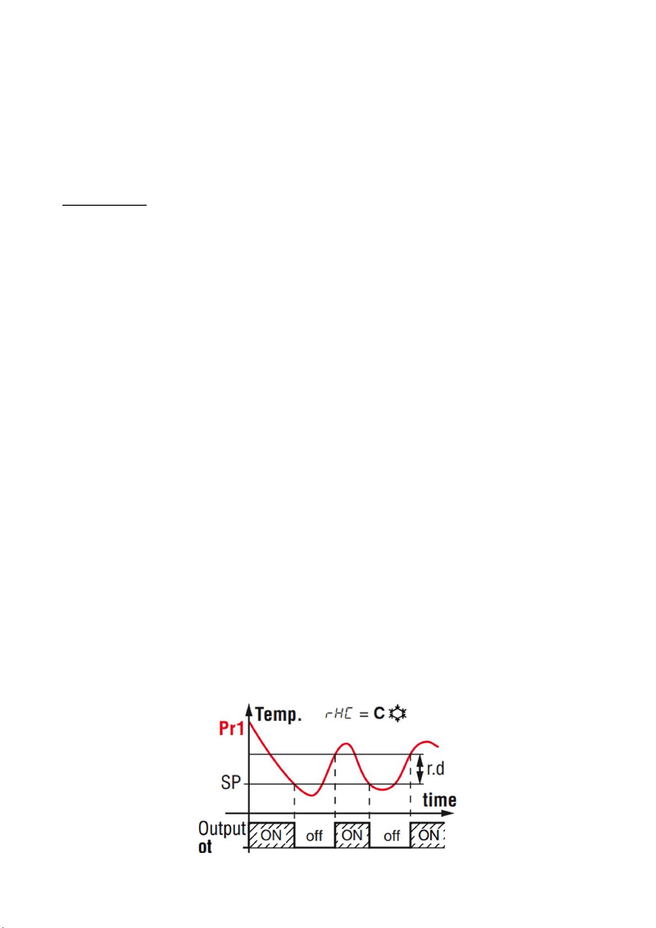
3.2.1 REGULATION
Once set a desired temperature required for the products storage within the operational range of
each models, the regulation of the cooling system is controlled by the temperature measured by
the control probe with a positive differential from the set point: when the temperature rises up to
the set point plus differential the compressor starts to pull down the temperature and it turns off
when the desired set point is reached again.
OPERATION
26
Use and Operational Manual
In case of faulty probe, the compressor activation is timed through the parameter “r.t1” and “r.t2”
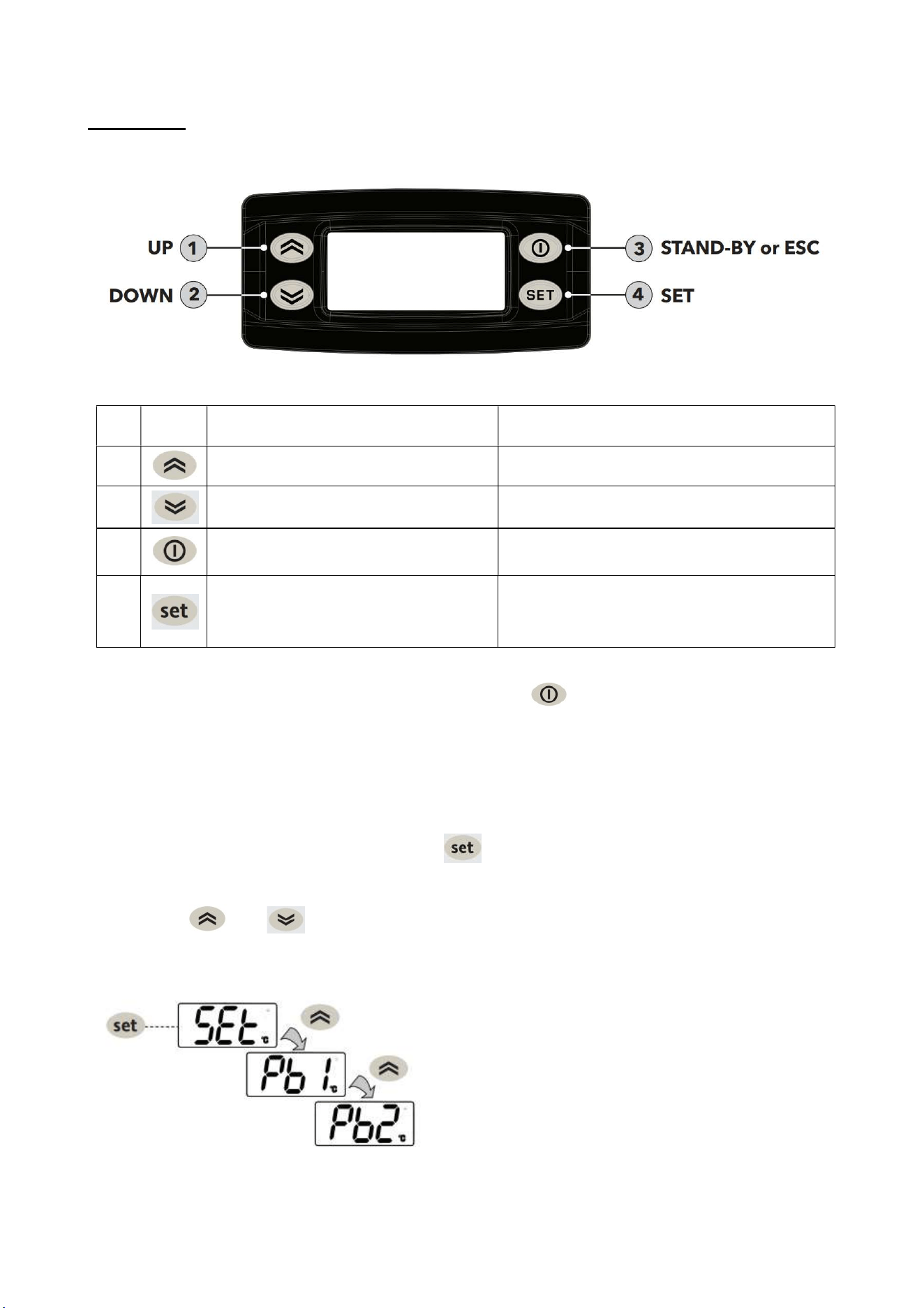
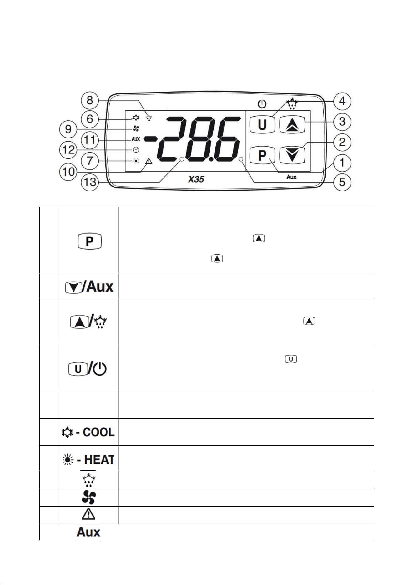
3.2.2 CONTROLLER USER INTERFACE AND MAIN FUNCTION
1
Used to set the Set Point (press and release) and to program the
function parameters (pressed for 5 s). In programming mode P is used to
enter at parameters edit mode and confirm the values. In programming
mode it can be used together with the key to change the
programming level of the parameters. When the keyboard is locked P
pressed together with the button for 5 s (or pressed alone for 9 s)
key to unlock the keyboard.
2
In programming mode is used for decreasing the values to be set and for
selecting the parameters.
3
In normal mode it can be used to start/stop a manual defrost (pressed
for 5 s). In programming mode is used to increase the value to be set
and to select the parameters. In programming mode, can be used,
together with key P to change parameters level. Pressed together with P
key for 5s allows the keyboard to unlock.
4
Press and release the key to display the instrument variables (measured
temperatures etc.).In programming mode press for 2 s to return in
Normal mode. Hold pressed for 1 s, while in Normal mode, to carry out
other functions such as turn ON/OFF (stand-by) the device.
5
Led SET
During the normal operating mode, signals that a key has been pressed.
In programming mode indicates the programming level of the
parameters: not protected (ON), protected (flashing).
6
Indicates the control output status (compressor or temperature control
device) when the instrument is programmed for cooling operation: on
(
on
), off (
off
) or inhibited (
flashing
).
7
Not applicable
8
Indicates: Defrost in progress (on) or drainage time in progress
(
flashing
).
9
Shows the Evaporator Fan(s) output status: on (on), off (off) or inhibited
(
flashing
).
10
Shows the Alarm active status (on), off (off) and Acknowledged or
Lached (
flashing
).
11
Shows the Auxiliary output status: on (on), off (off) or inhibited (flashing)
OPERATION
27
Use and Operational Manual
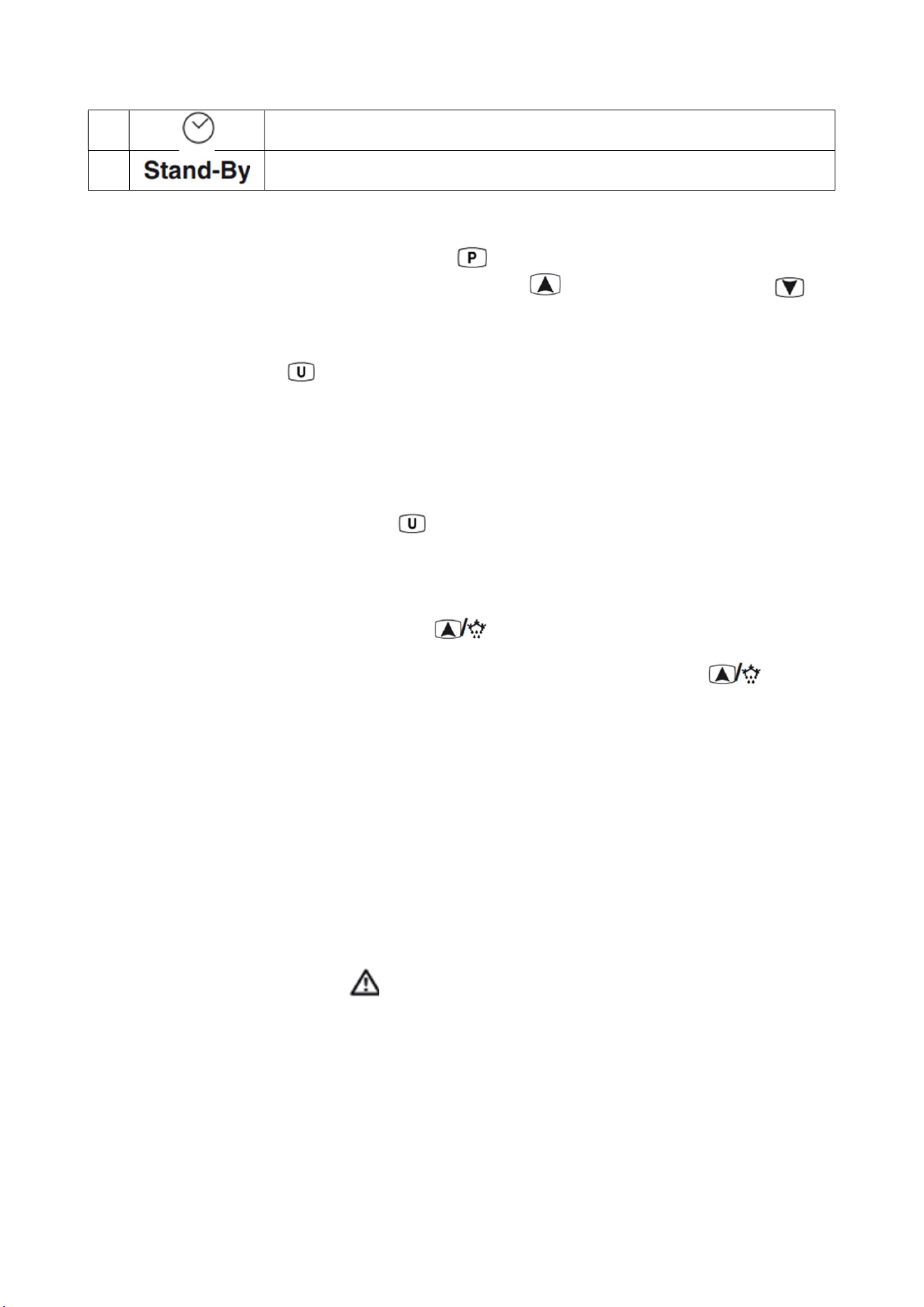
12
Indicates that the internal clock is running. (Not applicable)
13
When the instrument is in Stand-by mode is the only lit LED
3.2.3 SET POINT PROGRAMMING
To program the Set Point momentarily press the key, the display shows SP alternated to the
programmed value. To change the value shown press the key to increase its value or to
decrease it.
3.2.4 DISPLAYING MEASURED VARIABLES
In normal operation press to display the measured values:
PR1: air temperature.
PR2: evaporator temperature.
PR3: condenser temperature.
Lt: the lowest temperature read by Pr1 (air probe).
Ht: the highest temperature read by Pr1 (air probe).
Browse through the variable by pressing : the screen will display the variable label (for instance
PR2) and the associated value alternating.
To quit the procedure, do not operate on the controller for 60 seconds.
3.2.5 MANUAL DEFROST
To start manual a defrost cycle, press the key and keep it pressed for about 5 secs while the
instrument is in normal mode. After the key pressure, if the conditions are correct, the LED lights up
and the instrument performs a defrost cycle. To stop a defrost cycle, press the key and keep
it pressed for about 5 s during the defrost cycle execution.
Propane unit performs a hot gas defrost: when the defrost cycle is active a solenoid valve opens and
the compressor runs to by-pass the hot gas from the discharge line into the evaporator coil. The
defrost cycle ends when the evaporator reaches the d.tE temperature or the d.dE time is elapsed.
If the temperature measured by the evaporator probe is higher than the temperature set at the
parameters d.tS and d.tE defrosts are inhibited.
3.2.6 DIAGNOSTIC AND ALARMS
The alarm conditions of the instrument are the following:
- Probe errors: E1, -E1, E2, -E2, E3, -E3, E4, -E4;
- Temperature alarms: H1, L1, H2, L2;
- External alarm: AL, PrA, HP, LP;
- Open door alarm: oP;
During an event of alarm the LED lights on the screen and the buzzer gets activated. To mute
the buzzer press any key of the instrument.
Probe errors
When a probe error occurs, the screen displays the label (E) if the probe is interrupted or (-E) if
shorted. The probe may be also out of the reading range allowed by the controller.
In this case, check the status of the probe and the wiring connections. The probes used are NTC
type (10khom @25°C).
Temperature alarms
The temperature alarms work according to the air probe measurements.
OPERATION
28
Use and Operational Manual
The instrument has 2 temperature alarms (high temperature alarm: label H1 and low temperature
alarm: label L1), fully configurable with a maximum and a minimum threshold.
The temperature alarm is cleared only when the temperature return into the temperature alarm
threshold of a certain differential.
Temperature alarms
When the door digital input is activated the instrument shows the label oP alternated to the air
temperature. Elapsed the delay programmed at parameter A.oA, the instrument signals the alarm
activating the buzzer and lighting up the LED while continues displaying the label oP.
4. MAINTENANCE AND REPAIR
Maintenance and repair must be carried out by qualified personnel authorized by the manufacturer.
The manufacturer declines any responsibility for jobs carried out by unauthorized
personnel or the use of non-original spare parts.
4.1 ROUTINE MAINTENANCE
Prohibited to remove the guards and safety devices: It’s strictly forbidden to remove guards
or safety devices when performing routine maintenance operation. The manufacturer disclaims
all liability that may arise this regulation is not observed.
In case of FIRE:
- Disconnect the unit from the electrical power socket.
- Do not use water to extinguish the fire.
- Use powder or foam extinguishers.
4.1.1 Cleaning the interior and exterior of the appliance
The appliance is designed for the products storage so it is important to keep it clean. The equipment
is thoroughly cleaned at the factory before being shipped. We recommend, however, to clean the
interior cabinet before the first start up of the appliance. Before attempt any cleaning operation
make sure the power cord is disconnected.
-Cleaning product: use soft clean cloth wet with water and neutral detergent only.Do not use solvent
or bleach.
-Rinsing: use a cloth or sponge soaked with fresh clean water. Do not use water jet.
-Frequency: once a week or at different intervals in accordance with the type of product.
TROUBLESHOOTING
29
Use and Operational Manual
4.1.2 Condenser cleaning
The condenser is a heat exchanger. If it is dirty or clogged the air cannot circulate freely through the
same, it cannot discharge heat properly so reducing proportionally the performance and the
efficiency of the refrigeration system.
FOR THOSE REASONS IT IS IMPORTANT TO KEEP CLEAN THE CONDENSER COIL,
TYPICALLY MONTHLY.
Always switch off the unit and disconnect power cord before cleaning, it is dangerous
to do it with power ON: fan may start suddenly at any time.
Use a convenient ladder to reach the condenser. Use an air jet or vacuum with a soft dry brush if
necessary and remove any dust or fluff from the heat exchanger fins.
After cleaning, start the equipment.
During the cleaning operation wear gloves and safety glasses to protect yourself from any
injury
5. TROUBLESHOOTING
The Chart shows the most frequent breakdowns, possible causes and relative remedies:
PROBLEM DESCRIPTION POSSIBLE CAUSE SOLUTION
The appliance does not come on
The main switch is "off"
There is no tension
Other
Main switch “on”
Check plug, socket, electric connection
Contact technical assistance
The refrigerator unit does not start Set temperature is reached
Defrosting is in operation
Control Panel is broken
Other
Set new temperature
Wait for end of cycle, switch off and switch back
on
Contact technical assistance
Contact technical assistance
The refrigerator is continuously
working but does not reach the set
temperature
Room is too hot
Condenser is dirty
Refrigerant fluid is insufficient
Condenser fan has stopped
Door not properly closed
Evaporator is frosted up
Defrost valve is open
Air better
Clean condenser
Contact technical assistance
Contact technical assistance
Check door seals
Manual defrosting
Contact technical assistance
Refrigerator does not stop at set
temperature
Control Panel is broken
Temperature probe is broken
Door is not airtight
Contact technical assistance
Contact technical assistance
Close door
Ice blocks on evaporator Improper use
Control Panel is broken
Contact technical assistance
Contact technical assistance
Appliance is noisy Appliance not levelled
Contact with external bodies
Screws or nuts loose
Other
Check that appliance is level.
Check that no tube or ventilator fan is in contact
with external bodies.
Tighten
Contact technical assistance
Safety DC fan does not work Fan disconnected Re-wire the fan to the electrical strip contact

TROUBLESHOOTING
30
Use and Operational Manual
Stuck fan
Fan motor damaged
Replace the fan
Replace the fan
IN ORDER TO GUARANTEE THE EFFICIENCY OF THE APPLIANCE AND ITS CORRECT
FUNCTIONING THE MANUFACTURER'S INSTRUCTIONS MUST BE FOLLOWED AND
PERIODIC SERVICING MUST BE CARRIED OUT BY PROFESSIONALLY QUALIFIED
PERSONNEL.
(LEGAL REQUIREMENT FOR THE PREVENTION OF ACCIDENTS AT WORK AND THE
INSTALLATION OF ELECTRICAL APPLIANCES)
IT IS OBLIGATORY TO BE IN ACCORDANCE WITH POWER SUPPLY REGULATIONS
