Operang Instrucons for the
Classic 99
S ub-Ba ss
System
Cauon Marking Explanaon
The lightning ash with arrowhead symbol within an equilateral triangle is intended to alert the
user to the presence of un-insulated dangerous voltage within the product’s enclosure that may
be of sucient magnitude to constute a risk of electric shock to persons.
The exclamaon point within an equilateral triangle is intended to alert the user to the presence
of important operang and maintenance (servicing) instrucons in the literature accompanying
the appliance.
1

2
1 Read all of these instrucons.
2 Save these instrucons for future use.
3 Heed all warnings.
4 Follow all instrucons.
5 Do not use this apparatus near water.
6 Clean only with automove polish and micro ber cloth.
7 Install in accordance with the manufacturer’s instrucons.
8 Do not install near any heat sources such as radiators, heat registers, stoves or other apparatus (including
ampliers) that produce heat.
9 Do not defeat the safety purpose of the grounding-type plug. A grounding type plug has two blades and
a third grounding prong. The third prong is provided for your safety. If the provided plug does not t into
your outlet, consult and electrician for replacement of the obsolete outlet.
10 Protect the power cord from being walked on or pinched parcularly at plugs, convenience receptacles,
and the point where they exit from the apparatus.
11 Only use aachments/accessories specied by the manufacturer.
12 Use only with a cart, stand, tripod, bracket, or table specied by the manufacturer, or sold with the apparatus.
When a cart is used, use cauon when moving the cart/apparatus combinaon to avoid injury from p-over.
13 Unplug this apparatus during lightning storms or when unused for long periods of me.
14 Refer all servicing to qualied service personnel. Servicing is required when the apparatus has been damaged
in any way, such as power-supply cord or plug is damaged, liquid has been spilled or objects have fallen
into the apparatus, the apparatus has been exposed to rail or moisture, does not operate normally, or
has been dropped.
15 Minimum distances 10cm around the apparatus for sucient venlaon.
Important Safety Instrucons

16 The venlaon should not be impeded by covering the venlaon openings with items, such as newspapers,
table-cloths, curtains, etc.
17 No naked ame sources, such as lighted candles, should be placed on the apparatus.
18 Aenon should be drawn to the environmental aspects of baery disposal.
19 The use of apparatus in moderate climates.
20 Baeries shall not be exposed to excessive heat such as sunshine, re or the like.
Cauon: Any changes or modicaons not expressly approved by the party responsible for compliance
could void the user’s authority to operate this equipment.
Warning
To reduce the risk of re or electric shock, do not expose this apparatus to rain or moisture.
The apparatus shall not be exposed to dripping or splashing and no objects lled with liquids, such as vases,
shall be placed on apparatus.
The mains plus is used as disconnect device. The mains plug of the apparatus should not be obstructed OR
should be easily accessed during intended use. To be completely disconnected from the power input, the
mains plug of the apparatus shall me disconnected from the mains.
An appliance with a protecve earth terminal should be connected to a mains outlet with a protecve
earth connecon.
Design Safety
These apparatus are supplied with a detachable mains cord. For 230V operaon a 4A fuse is ed in
the socket, for 120V operaon a 8A fuse is ed. Should the fuse need to be replaced use a similar rated
fuse approved to ASTA or BSI 362 standards. Do not use without the fuse cover in place. Replacement fuse
covers are available from your distributor.
3
4
Aenon Explicaon Marquage
L’éclair avec le symbole de pointe de èche dans un triangle équilatéral est desné à alerter
l’ ulisateur de la présence de non isolée tension dangereuse à l’intérieur de l’enceinte du
produit qui peut être d’une ampleur susante pour constuer un risque d’électrocuon pour
les personnes.
Le point d’exclamaon dans un triangle équilatéral est desné à alerter l’ulisateur de la
présence d’instrucons dans la documentaon accompagnant l’appareil exploitaon et de
maintenance (entreen).

4
5
1 Lisez aenvement ces instrucons.
2 Conservez ces instrucons.
3 Respectez tous les averssements.
4 Suivez toutes les instrucons.
5 Ne pas uliser cet appareil près de l’eau.
6 Neoyez seulement avec du vernis automobile et ssu microbre.
7 Installer conformément aux instrucons du fabricant.
8 Ne pas installer près de sources de chaleur telles que des radiateurs, registres de chaleur, poêles ou autres
appareils (y compris les amplicateurs) qui produisent de la chaleur.
9 Ne pas contourner le disposif de sécurité de la prise de terre. Une che de terre a deux lames et une
troisième broche de mise à la terre. La troisième broche est fournie pour votre sécurité. Si la che fournie
ne rentre pas dans votre prise, consultez un électricien pour le remplacement de la prise obsolète.
10 Protégez le cordon d’alimentaon ne soit piéné ou pincé, en parculier au niveau des ches, des prises
de courant, et le point de sore de l’appareil.
11 Ulisez uniquement des xaons / accessoires spéciés par le fabricant.
12 Ulisez seulement avec un chariot, stand, trépied, support ou table spécié par le fabricant, ou vendu
avec l’appareil. Lorsque vous ulisez un chariot, soyez prudent lorsque vous déplacez l’ensemble chariot /
appareil pour éviter les blessures en cas de chute.
13 Débranchez cet appareil pendant un orage ou lorsqu’il est inulisé storsm pour de longues périodes de temps.
14 Conez toute réparaon à un personnel qualié. Une réparaon est nécessaire lorsque l’appareil a été
endommagé de quelque façon que ce cordon d’alimentaon ou la che est endommagé, du liquide a
été renversé ou des objets sont tombés dans l’appareil, l’appareil a été exposé à rail ou à l’humidité, ne
fonconne pas normalement, ou a été échappé.
Informaons Importantes Relaves a la Securite

15 10cm distance minimale autour de l’appareil pour une aéraon susante.
16 Il convient que l’aéraon ne soit pas gênée par l’obstrucon des ouvertures d’aéraon par des objets tels
que journaux, nappes, rideaux, etc.
17 Il convient de ne pas placer sur l’appareil de sources de ammes nues, telles que des bougies allumées.
18 Il convient d’arer l’aenon sur les problèmes d’environnement dus à la mise au déchet des piles.
19 Si l’appareil est desné à être ulisé sous un climat tempéré.
20 Les baeries ne doivent pas être exposées à une chaleur excessive telle que celle du soleil, d’un feu ou d’origine.
Averssement
Cet arcle est lourd. Pour éviter tout risque de blessure, prendre soin lors de la manipulaon.
L’ appareil ne doit pas être exposé à des éclaboussures et aucun objet rempli de liquide, comme des vases,
ne doit être placé sur l’appareil.
Les conduites Plus est ulisé comme disposif de déconnexion. La che de l’appareil ne doit pas être
obstruée OU doit être facilement accessible pendant l’ulisaon. Pour être complètement déconnecté de
l’alimentaon électrique, le cordon d’alimentaon de l’appareil doit me débranché.
Un appareil avec une borne de terre doit être branché sur une prise de courant en étant relié à la terre.
Aenon: Tout changement ou modicaon non expressément approuvés par la pare responsable de la
conformité pourraient annuler l’autorité de l’ulisateur à uliser cet équipement.
Sécurité Design
Ces appareils sont fournis avec un cordon secteur amovible. Pour un fonconnement à 230V, un fusible
de 4A est installé dans la prise, pour un fonconnement à 120V un fusible de 8A est installé. Si le fusible
doit être remplacé, ulisez un fusible de même calibre approuvé selon les normes ASTA ou BSI 362. Ne pas
uliser sans le couvercle du fusible en place. Des couvercles de fusibles de rechange sont disponibles auprès
de votre distributeur.
6

7
Welcome to the REL Family. If you already belong, welcome back!
Shortly aer introducing the Classic 98, we began to receive requests from customers and dealers to deliver
a larger, more powerful model. Ancipang this request, we proacvely developed a gameplan and specic
amplier/driver combinaons to a high level even before launching the smaller 98. Whilst Classic 99 retains
the walnut veneer and vintage form factor of a late 90’s era REL, it also boasts 450 was and a long travel
12” (300mm) bass driver. It would thus be easy to see this as simply a larger/higher output/deeper bass
version of the Classic 98.
You would be wrong.
During our usual bale to achieve renement we invesgated shiing cabinet volumes, specic
insulaon types, and numerous renements to the drivers and lters. And we began to see something
emerging. Something special.
We present you with Classic 99. A model that is far more than the obvious massive increase in power,
and hence, output. A model whose 12” driver and cabinet yields far deeper bass extension. A subwoofer
larger, heavier, more substanal than its fraternal mate, Classic 98.
Classic 99 is special because in addion to playing 30% louder, in addion to extending some 4 to 5Hz
lower in our development studio, it is simply BETTER. Beer in that way that REL always seeks, in ways both
large and small. And in ways that result in inverse improvements. These are nuanced enhancements that
elevate sound quality, transparency, and dynamic range that one would not ancipate from simply a more
powerful model. Classic 99 is more transparent throughout the enre audio range. It is capable of greater
dynamic contrasts both large and small, it is both more subtle and more outright thunderous. And it is more
dexterous and lighter on its feet, which is a rare and beauful thing to hear.
It is also a crushingly powerful theatre subwoofer, especially when used as rear channel subs in a large
HT/3D-enhanced system; a REL method of achieving Dolby’s stated goal of providing deep, extensional bass
response throughout ALL the channels of theatre whilst also delivering exceponal .1/LFE special eects-rich
bass. Its use in the rear channels is spectacular. As is its value; we’ve worked, as always to keep our prices as
reasonable as possible.
This is a special accomplishment that allows us to push the envelope in mulple direcons simultaneously
and sll deliver remarkable value.
Enjoy – John Hunter
Dear Friend and Valued Customer

8
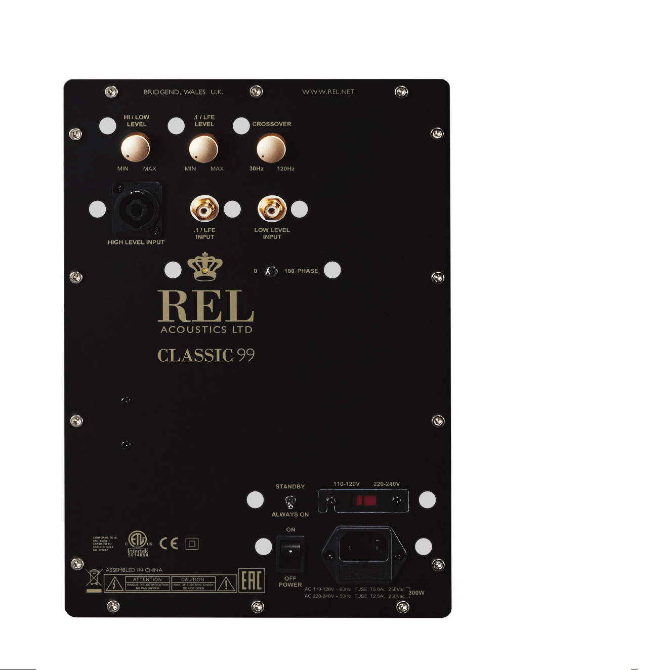
1 HI/LOW LEVEL INPUT: Used to adjust the output of either the High Level or Low Level input.
2 .1/LFE LEVEL: Used to adjust output level when using .1/LFE Input from a surround sound processor.
3 CROSSOVER: Used to adjust crossover frequency of HI/LOW LEVEL channel. Variable between 30 to 120Hz.
4 HIGH LEVEL INPUT (Neutrik Speakon): Used to connect to the main front amplier speaker terminals.
5 .1/LFE INPUT (RCA): Used to connect to the .1/LFE output of a surround sound processor.
6 LOW LEVEL INPUT (RCA): Used to connect Low Level signals to the sub-bass system from the output of a
preamplier, integrated amplier or receiver. (For home cinema use, use .1/LFE INPUT).
7 On/O LED: Power On/O indicator.
8 PHASE: Used to set Phase to 0 or 180 degrees.
9 STANDBY/ALWAYS ON: Used to toggle between STANDBY (up), and ALWAYS ON (down).
10 Mains Select Switch: Slide switch used to set input AC between 120V and 230V.
11 ON/OFF POWER Switch: Used to turn unit on or o.
12 IEC Mains Socket: Fused mains (AC) input socket that accepts detachable power cord. Replacement
fuse may be found inside the compartment beneath the a/c plug.
REL Classic 99 Rear Panel Connecon Legend
9
8
9 10
11 12
1 2 3
4 5 6
7

10
HIGH LEVEL INPUT
Connecons should be made to the same binding post on main amplier as the main speakers. Red to
main amplier right speaker posive terminal, yellow to amplier main le speaker posive terminal and
black to a ground lug or chassis screw. See Connecng and seng up secon below for details on integraon
with Class D and Dierenal type amplier designs. Plug the Neutrik® Speakon® plug into the HIGH LEVEL
Speakon® socket.
.1/LFE INPUT
This requires an RCA to RCA cable and is a dedicated true .1 Channel. This circuit therefore eliminates the
normal Natural RollO™ Crossover and passes the .1 Low Level signal through with only the required 120Hz
fourth-order lter.
LOW LEVEL INPUT
This RCA input allows for convenonal connecon from a preamplier. This connecon is necessary when
using powered speakers or when connecng to certain soundbars. Connect from either the le or right low
level output from a pre-amplier to the REL’s LOW LEVEL INPUT RCA.
Phase Switch
Used to set phase. Phase selecon aects all inputs (High Level, Low Level and .1/LFE). Used to set Phase
to 0 or 180 degrees.
Crossover
The Crossover aects High and Low Level inputs. The .1/LFE signal does not pass through the Crossover circuit.
Connecvity and Funconality

11
Always switch o your system before disconnecng any wires.
To increase the versality of connecng up, the Classic 99 models have three separate inputs. A High Level
input socket, a .1/LFE RCA input, and a Low Level RCA input. This is to facilitate use with both two-channel
stereo systems and AV surround sound systems.
The High Level, unbalanced, dual-channel (stereo) input is via a Neutrik® Speakon® connector is designed to
accept the stereo (two-channel) signals from the speaker terminals of your receiver, integrated amplier or
basic amplier. This has the advantage of ensuring that your subwoofer receives exactly the same signal as
the main speakers, which means that the character of the bass from the main system is carried forward into
the Sub-Bass System.
This is a very important point and together with REL’s Natural RollO™ circuitry, ensures far superior system
integraon of the Sub-Bass System with the main system.
STOP! Please read the following or damage can occur. Do not force the Neutrik Connector into its socket on
the rear of the amplier. Please study the Neutrik and note that the cable’s black and blue plug has a black
key, a part that locates into a corresponding slot on the amplier. Line up the cable’s connector with this slot
on the amplier, insert fully into socket and rotate clockwise unl a so “click” is heard.
To remove the Neutrik® Speakon® plug, grip body of plug, place thumb on chrome lever, move lever
backwards, rotate plug anclockwise quarter turn and withdraw.
There is a single RCA socket for Low Level connecon to the output of a stereo preamplier or receiver.
Another single RCA socket connects to the .1/LFE output of a home cinema processor.
HIGH LEVEL and .1/LFE inputs can be used simultaneously. The benets are two-fold when used with a
home cinema processor. The .1/LFE input reproduces the .1/LFE channel and the High Level connecon
underpins the main front speakers. The main front speakers should be set to the ‘Large’ opon on the
processor. See “Theatre Applicaons” for more informaon.
Connecng Up

12
REL products are not tradional subwoofers, but true Sub-Bass Systems. A REL is designed to augment the
performance of “full range” speaker systems in order to provide, in certain cases, linear response below
15Hz. Therefore, for the moment, please set aside everything you’ve been taught about subwoofers and
how they are integrated into a stereo or home cinema system. REL Sub-Bass Systems set-up and posioning
diers from convenonal subwoofers. A REL will take advantage of physics and room acouscs to provide
deep pressurizaon as no tradional subwoofer can. It is important that you bring to the set-up process a
willingness to do things a lile dierently in order to obtain these superior results. The end result of your
labors will be an uerly seamless integraon of true deep bass to a sound system, regardless of the main
speakers’ low bass capability.
Basic set-up should take no more than ten to een minutes to accomplish once connected.
Two Things Before You Begin
1 It is helpful to know that you will almost always connect the REL to the input on the rear panel labeled
“HIGH LEVEL INPUT.” This connecon is made using the supplied 33’ 6” (10 meters) cable, the bare leads
of which connect to the speaker output terminals of the power amplier. The easy and foolproof connecon
at the REL is done with a Neutrik® Speakon® connector. The purpose of connecng to the speaker output
terminals is one of the unique secrets of REL’s success. By connecng to the HIGH LEVEL INPUT on the REL
from the amplier, you build forward the sonic signature of your main system, including the tonal balance
and ming cues of the enre electronics chain. In this way, the REL is fed the exact signal that is fed to the
main speakers
2 When possible, the REL should be placed in one of the corners behind the speakers. Remember, we are
dealing with true LOW bass pressurizaon with RELs. Low bass pressurizaon below 40Hz is best derived
from corner placement, where the most linear and ecient low bass can be produced because the
subwoofer is able to take advantage of the tangenal (corner-to-corner) axis which is typically the
longest axis in a room. Corner posioning requires drawing the subwoofer slowly out from the corner aer
Phase, Gain and Crossover sengs have been properly set. Draw it on a 45 degree diagonal away from
the corner while moving slowly, listening for small increases in deep bass energy. Pause and assess each
me a bass node is encountered. Generally, a range between 4”(100 mm) and 1’ (305 mm) out from the
corner will result in achieving cleaner, more open sounding bass, while retaining good deep bass.
REL Set-Up Made Simple

13
Connecng and Seng Up
High level connecon, using the enclosed cable with the Neutrik® Speakon® connector, is always the rst
choice. This connecon can be made without aecng the performance of the amplier because the REL’s
amplier input impedance is 150,000 ohms, in eect producing NO addional load on the rest of your system.
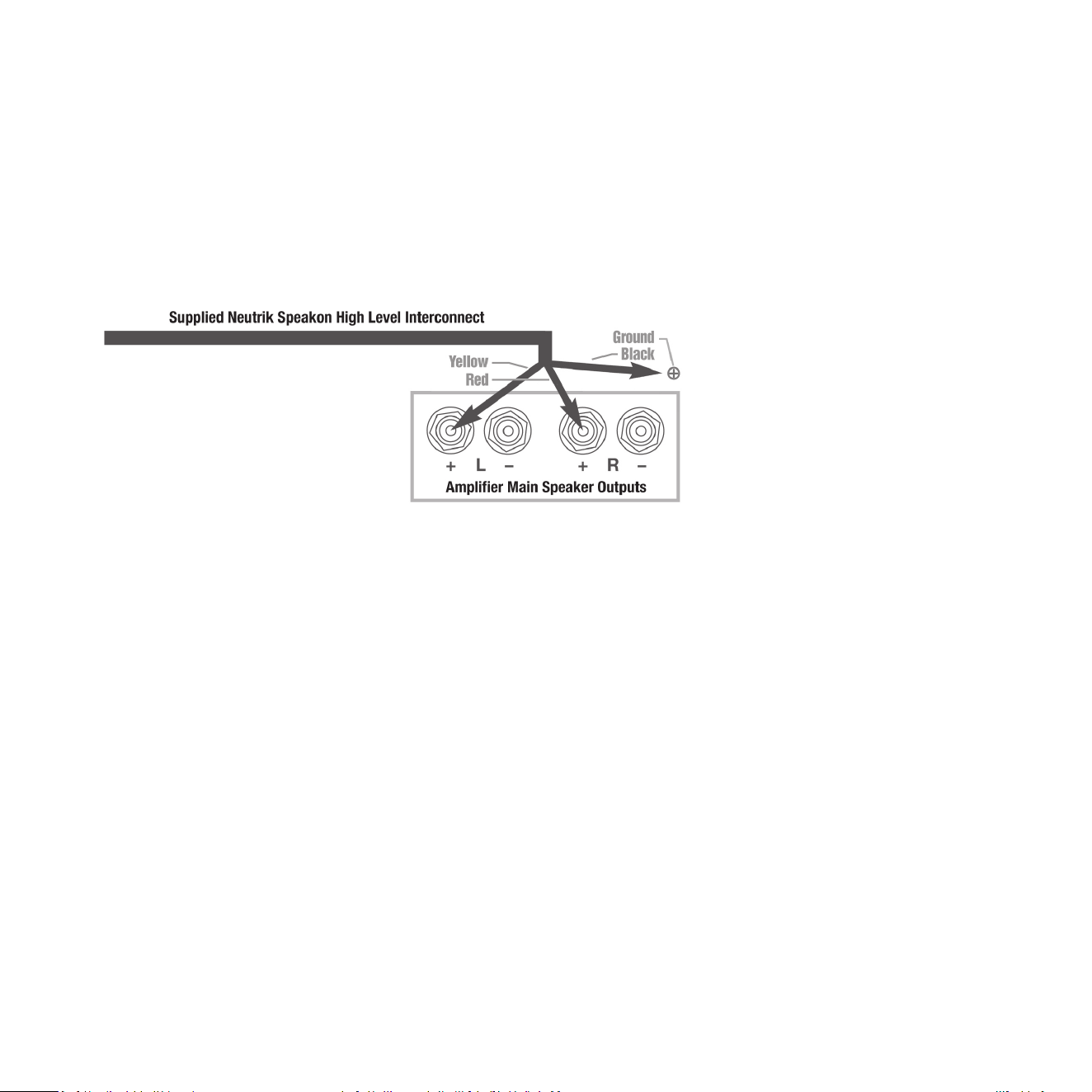
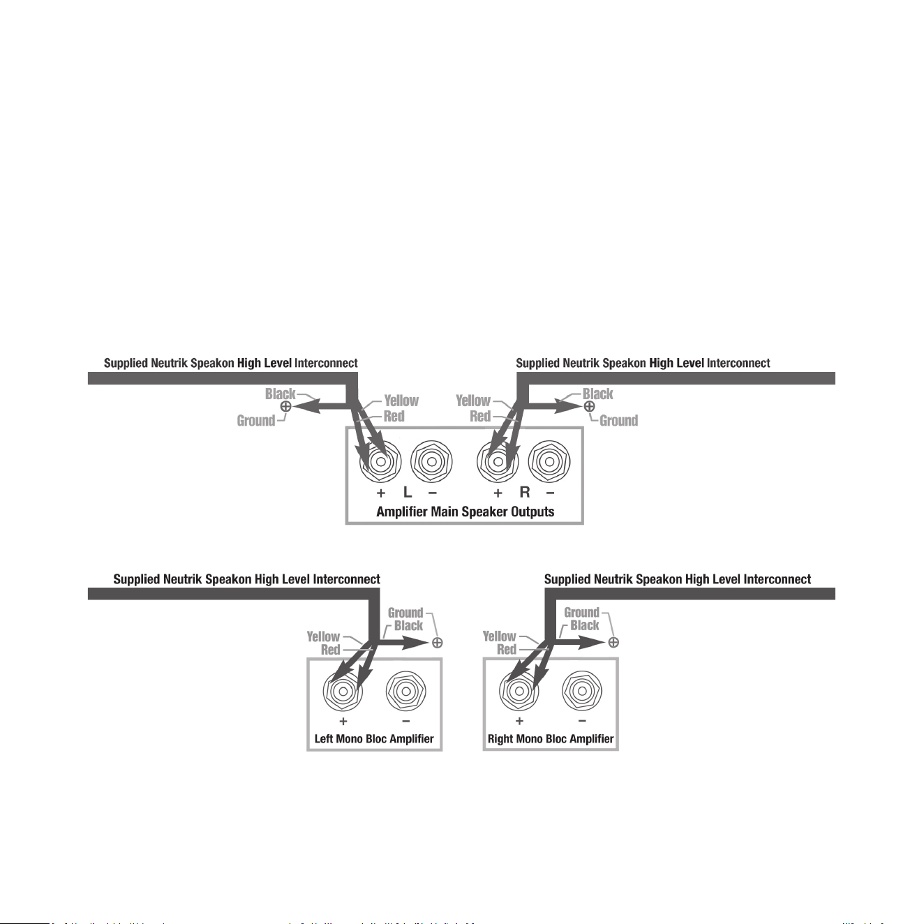
• The standard High Level hook up procedure is: aach the red wire to the amplier’s right posive speaker
output terminal; aach the yellow wire to the amplier’s le posive speaker output terminal; aach the
black wire to a ground lug on the amplier or a pre-amp or a chassis screw; plug the Speakon® connector
into the Sub-Bass System’s HIGH LEVEL INPUT.
Standard High Level
14
• For Dierenal(i.e. fully balanced) ampliers using one REL, simply use the standard connecng scheme
above. Connect the black wire to a ground lug or chassis screw. Should hum occur using this method, the
black wire should be allowed to “oat” or hang down without connecon to ANY terminal.
Please contact your dealer should there be any quesons concerning this or any other hookup procedure.
NOTE: Classic 99 models are equipped with internal circuitry to allow connecon to many Class D
(digital) ampliers.
Warning: Do NOT connect the black wire to the main Class D power amplier’s speaker negave terminal.
Some Class D ampliers produce voltage at the amplier’s negave terminal and connecng the REL’s black
wire will produce an undesirable short to ground. If connecng to a Class D amplier, follow the above
connecon procedure for dierenal ampliers.
Dierenal (i.e. Fully Balanced)
15
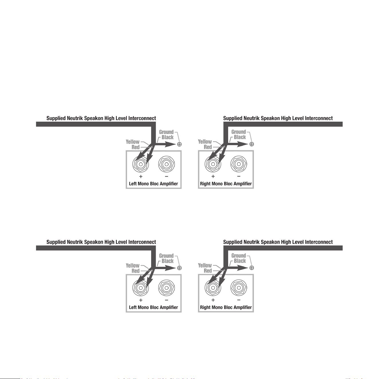
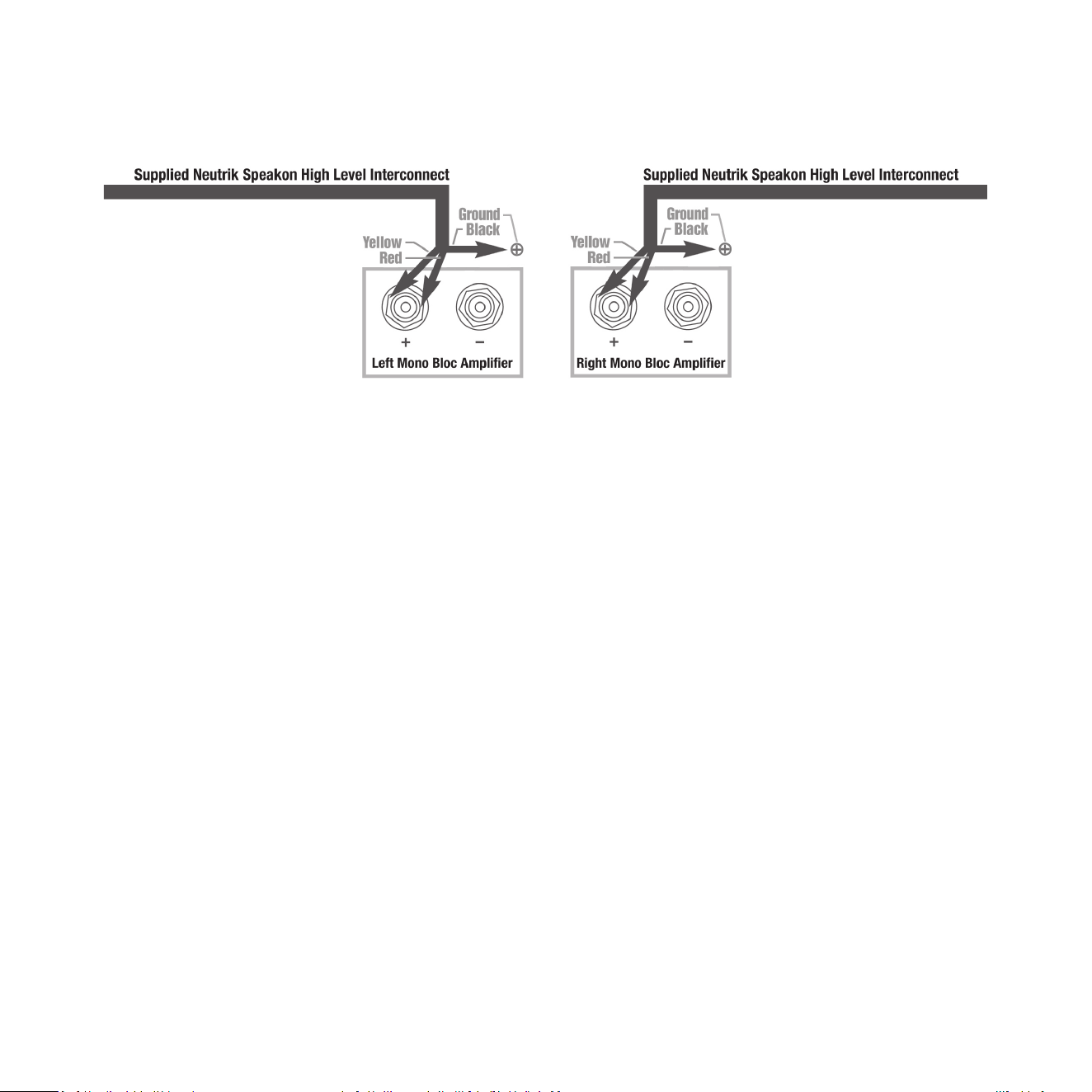
• When connecng RELs to Mono Bloc ampliers (2) RELs, one for each amplier, must be used. Connect the
black wire of each REL to a ground lug or chassis screw of each amplier; twist together the red and yellow
wires of each REL separately and connect each pair to the posive speaker terminal of the corresponding
amplier channel. In some instances, this will result in exceponally high gain (output) from the RELs. If it
seems simply too high in gain, please remove either the red or yellow wire from the twisted pair. This will
reduce output by half and restore a natural dynamic.
If the amplier is of balanced dierenal design, please follow the instrucons in the secon above labeled
Dierenal Connecon.
Mono Bloc
Mono Bloc Dierenal
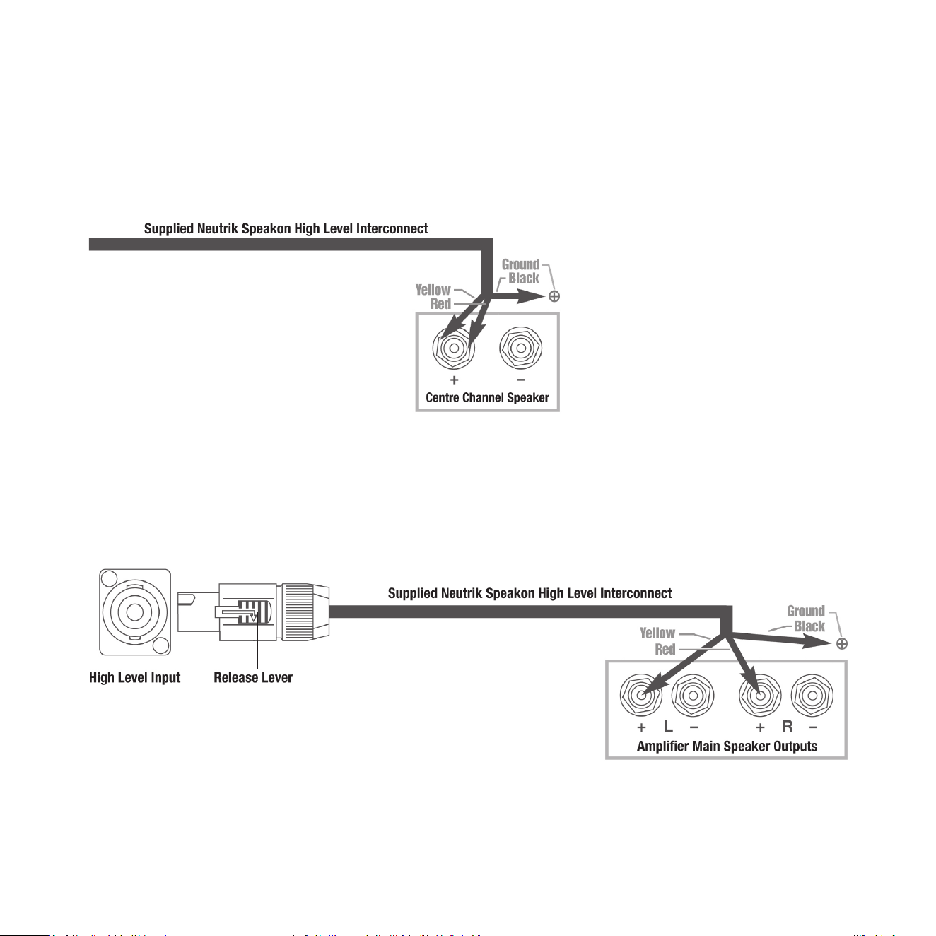
• If connecng a single REL as a dedicated centre channel sub, twist together the red and yellow wires and
connect these paired wires (red/yellow paired together) to the posive centre channel amplier terminal.
Connect the black wire to a ground lug or chassis screw on the amplier.
• If connecng a REL as a dedicated rear channel sub, connect the yellow wire to the le rear posive
speaker terminal; connect the red wire to the right rear posive speaker terminal, connect the black
wire to a ground lug or chassis screw. If the amplier is of balanced dierenal design, please follow the
instrucons in the secon above labeled Dierenal Connecon.
16
Dedicated Centre Channel
Dedicated Rear Channel

17
Low Level connecon (via RCA connector) is always an opon if High Level connecon is not possible.
When connecng to the LOW LEVEL INPUTS in a system in which High Level connecon is not possible, such
as if using internally-amplied speakers, connect le and right RCA cables between the LOW LEVEL INPUT jacks
of the REL and the le or right channel output of your preamplier. In some cases, these channels can be
combined with a “Y” cable or a dedicated SUB output.
Please consult your pre-amplier’s/integrated amplier’s manufacturer before connecng with a “Y” cable.
When connecng to a home cinema system where there is a .1/LFE channel output, connect a single RCA to RCA
cable between the sub output of the processor/receiver and the .1/LFE INPUT jack on the REL.
1 Posioning
The opmal posion for a single REL Classic 99 is in one of the corners behind the main speakers. This
posion provides 9 dB of mechanical amplicaon and allows for the most linear true low bass wave
launch, owing to the ability to tune the REL’s crossover to the longest distance in the room in order to
produce the longest, therefore lowest frequency, bass waves.
1a Stereo Set-Up of Classic 99
(see page 19 through 21 for Stereo Set-Up procedure). When this step has been completed, proceed to
Number 2, immediately below.
2 The Process
To begin the set-up process, choose a piece of music that has a repeve bass line that is very low in
frequency. We suggest track 4 from the soundtrack to Sneakers (Columbia CK 53146). This has a repeve
bass drum throughout that gives you plenty of me to move the woofer around, but more importantly,
the venue was quite large for this recording, and therefore it has a very deep and large-scale bass
signature. This track is perfect for the set-up process and should be played at the highest reasonable
level expected for system playback.
Working with a partner, one in the listening posion and one at the REL manipulang the controls, is
the most eecve and ecient way to set up the REL. If working alone, the inial steps in the set-up can
be very eecvely carried out from the locaon of the REL. Trying to ignore all other music in the track,
listen for the bass drum and its eect on the listening room.
3 Phase Orientaon
Once in the corner, we need to adjust for phase. This may be the single most crical step, and because
it really is quite simple, it is oen over-thought. Keep in mind; the right phase is whichever posion is
the loudest or fullest. While playing music with true low bass, adjust the crossover to a point where the
REL and the speaker are sure to share frequencies at 50Hz on the crossover control, or slightly higher

18
for smaller speakers. At this point turn the HI/LOW LEVEL control up so that both the REL and speaker are
roughly equal in volume and then switch, using the phase switch, set phase to 0 or 180 digrees. Again,
whichever posion is loudest or fullest is the correct posion. That is, when the posion is working in
harmony with your main speakers, reinforcing bass, not canceling it.
4 Corner Fine Tuning
(When seng up for Stereo Classic 99 it is Possible that Placement is Not Corner Loaded and this Step
May be Omied). The next step is to determine precisely how far from the corner the sub should be
placed to achieve the most ecient output, as well as the lowest frequency extension. With the REL fully
into the corner, and poinng straight out along the diagonal coming out of the corner, connuing to play
the music, slowly pull the REL from the corner on the diagonal, equidistant from both side and rear wall.
At a certain point (somemes a maer of only a few inches, in rare cases a foot or more) the REL will
audibly go lower, play louder, and, if it truly locks on to the room and is fully pressurizing it, the air around
the REL will seem to be energized, stop right there! This is the correct posion from the corner for the REL.
5 Orientaon
Once the posion from the corner has been established, the orientaon of the woofer must be determined
by rotang the REL from an imagined centre point at the rear of the REL. As the REL is moved from one
side to the other listen for the greatest level of output and bass linearity. In eect, the REL should be le
in the posion where it is playing the loudest and lowest.
6 Crossover and Level Sengs
To determine the crossover point, take the volume of the REL (using the HI/LOW LEVEL control) all the way
down, and put the crossover to 30Hz. At this point, bring the REL’s volume back up slowly to the point
where you have achieved a subtle balance, i.e. the point at which you can just hear the Classic 99 even
with the main speakers playing. First, bring the crossover point up unl it is obviously too high; now gently
reduce frequency to the appropriate seng. For all intents and purposes, this is the correct crossover
point. Once this stage has been reached, subtle changes to volume and crossover may be accomplished
to provide the last bit of complete and seamless integraon. With that, set-up is complete.
Hint: There may be a tendency to set the crossover point too high and the volume of the Sub-Bass System
too low when rst learning how to integrate a REL with the system, the fear being one of overwhelming the
main speakers with bass. In making this common error, the resulng set-up will be lacking in bass depth and
dynamics. The proper crossover point and volume seng will increase overall dynamics, allow for extended
bass frequencies, and improve soundstage properes. Note, volume adjustments may need to be made to
oset the eects of crossover changes. In general, when selecng a lower crossover point, more volume may
need to be applied. Higher crossover frequencies will generally necessitate less gain.
19
Stereo Set-Up of REL Classic 99
Stereo Sub-Bass is advised for the fastest, clearest, deep bass—not for more output. Convenonal wisdom
has it that stereo subs results in between +3 and +6 db addional output depending upon posioning. In
and of itself, this is of only passing interest in most instances since even a single Classic 99 is capable of
profound output. What then, is the point to adding a second stereo sub bass Classic 99?
In a word, clarity. Clarity that permits “seeing” back into the farthest reaches of the sound stage. Clarity
that illuminates all dimensions of the musicians and the space that they inhabit equally and enhances the
natural reality of a great full range system, as only RELs can. Stereo Classic 99 produce clarity, transparency,
speed and low-level detail NOT just in the bass but throughout the enre spectrum of music.
Stereo
Mono Bloc
20
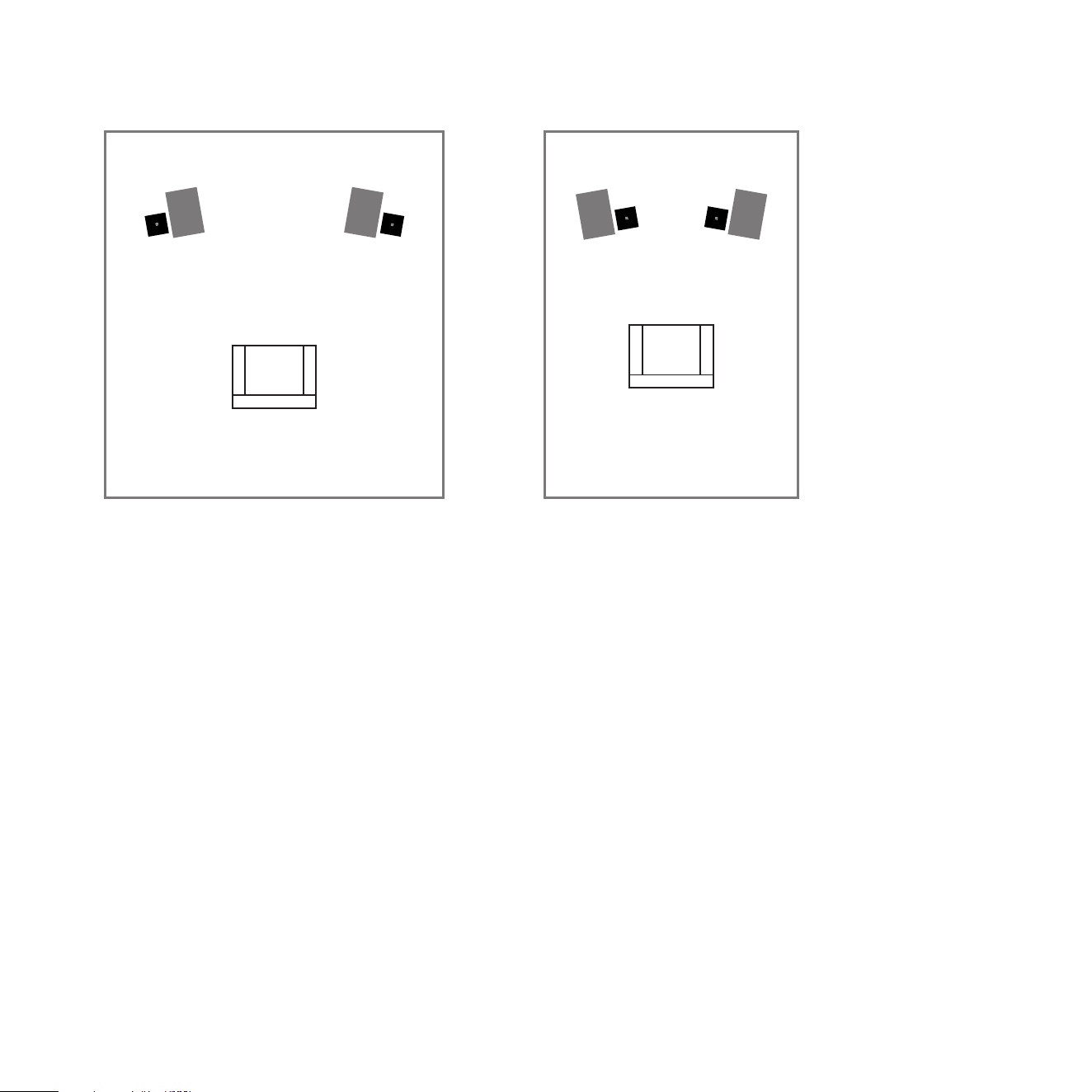
Expert Set-Up: Preferable is to bring the subs further out into the room and place them slightly behind and
outboard of the main speakers.
1 Set each side up independently. Disconnect the sub that is not being set-up so your complete focus can
be given over to the sub that is being set-up. Carefully follow the guidance provided in standard set-up if
you are unfamiliar with standard REL set-up procedure for gain, phase and crossover sengs.
2 Carefully ne-tune the posion of the sub in its recommended locaon (slightly behind and to the outside
of the main speaker) listening for rich powerful room nodes, but focusing on speed and connecon with
the main speaker. Since there will be a preponderance of output available to a stereo Classic 99 owner,
focusing on connecon with and blending with the main speaker becomes the primary focus, not merely
raw output.
Mono Bloc Dierenal
21
3 Once each sub has been carefully tuned, aach the cables for both subs. At this point, the output
achieved will be too loud and will require re-seng the volume/gain control of each Classic 99 lower. This
is normal as the combined output is likely to be at least 3 db louder with both subs now being used. Using
the supplied remote, carefully turn down each sub unl perfect balance is achieved. While turning the
le or right sub gain down, it is helpful to turn slightly and even lean slightly toward the side that is being
adjusted to beer achieve focus and a balanced sound level more quickly.
Listening Chair
Normal Room
Listening Chair
Narrow Room

22
Theatre Applicaons
For Dolby Digital AC3 or other 5.1 theatre systems, once the standard set-up for two-channel outlined
above is complete, the LFE output from the processor or receiver should be connected to the .1/LFE INPUT
and appropriate volume adjustments made using the .1/LFE level control. For this conguraon, you must
set the processor to the “large” or “full range” seng for the le and right speakers in order for the REL to
receive the bass signal via the high-level cable. In this conguraon, the REL provides support for both the
le and right speakers for two-channel listening, and support for the LFE when movies are playing. Most
processors will allow you to defeat the subwoofer output when listening in the two-channel mode. The
eect of this set-up is one of greatly increased dynamics in the mid-bass range, no bass bloat, and a greater
degree of space and ming from the special audio eects. For an even greater sense of space and impact,
a second REL connected in parallel to the centre channel will prove to be a dramac improvement as well.
And if that is not enough, a rear REL, both to support the rear channel speakers as well as to evenly distribute
LFE through the room, truly completes the full-range sonic picture for state-of-the-art lm reproducon.
Running In
Care taken during run in will be rewarded by many years of pleasurable use. Both the electronics and the
drive unit will benet from an inial period of carefully controlled use. Possible damage may be sustained
by running in the unit at too high a volume seng over an extended period. On the other hand, by taking a
lile care over this inial period, about 24 hours of actual use, a longer life with a higher potenal eventual
performance is assured.
Care and Polishing
The cabinets are best maintained by using a clean so cloth on the veneer.

23
Overload Protecon
All REL Sub-Bass Systems are designed as true sub bass speakers. They are designed to reproduce those
exceponally deep notes that are felt as well as heard. This it will aempt to do at whatever volume level you
set. If set too high no damage should result because the built-in electronics will limit the cone movement.
This electronic control is called Set-Safe™. It constantly and instantaneously monitors the output from the
power amplier and is totally transparent in operaon unl required. This means it has absolutely no eect
on the sound quality of your REL unl an overload is detected.
Ordinarily an overload would cause the power amplier to go into clipping with resultant loss of control
over the drive unit. This can cause drive unit damage, and always sounds nasty. Set-Safe™ detects the point
of incipient clipping and gently so-clips the waveform of the signal to ensure actual clipping does not occur.
This is a necessarily simplied descripon of what actually happens, but in eect, Set-Safe™ controls the
amplier and ensures there is minimum risk of amplier and driver damage caused by over-driving.
A thermal overload device is ed to all Classic 99 Sub-Bass Systems. If the unit is deliberately over-driven
this device will sense the temperature rise and cut the output; recovery me is approximately ve minutes.
If this happens, it is a warning that the unit is being over-driven and the volume level control should be
reduced to a safe level.
Although everything possible has been done to minimize risk of thermal overload failure, there can be
no defense against those individuals who deliberately abuse the device. Such damage is NOT covered by
warranty. Please remember your REL is there to supplement your main system, not overwhelm it!

24
Power Saving Eciency
All REL Sub-Bass system designs ulize a true POWER ON-OFF switch that aords the owner the ability to
turn o their unit completely, without having to unplug the A/C mains cord. When a REL Sub-Bass System is
switched o using the POWER ON-OFF switch on the rear panel it draws ZERO power.
In addion to the power switch there is an ALWAYS ON/STANDBY mode switch has two posions.
Up engages the STANDBY circuit and down keeps the unit always on.
The Classic 99 features a standby mode that is enabled when the mode switch on the rear of the unit is set to
the “STANDBY” posion. In this mode, the input signal is constantly monitored for audio acvity. If no audio
informaon is detected over a period of 30 minutes, the unit will enter a low power standby mode in which
less power is consumed. When input signal acvity is detected, the unit resumes normal operaon. By using
the standby mode, you can ensure that there is no unnecessary power draw when the unit is not in use.
Note: Due to variaons in program material, it is impossible to produce a perfectly reliable standby circuit.
Bass rich music or eects will consistently trigger our standby circuit whilst content that is low in volume and
possesses lile or no bass cannot be relied upon to trip the standby funcon.
Alternavely, the user has the opon to leave the unit in the normal operaon mode at all mes by selecng
the “ALWAYS ON” posion of the power mode switch. Leaving a REL on produces the best sonic performance
and the most reliable operaon. In this mode, the unit will not enter standby regardless of whether or not
there is acvity at the input. Using this seng ensures that the Classic 99 is ready to react instantaneously to
bass transients, whether in music or lms.
Model Power Draw at Standby Power Draw at Idle
Classic 99 > 0.5 Was 13 Was

25
Type: Closed box, down-ring driver
Acve Drive Unit: 12 in. (305mm) Amended Pulp-on-Paper,
Downring Inverted Cone, Steel Chassis
LF Response in Room: -6 dB at 24Hz
Input Connectors: High Level Neutrik Speakon, Low Level RCA, .1/LFE RCA
Gain Control Range: 80 dB
Power Output: 450 was (RMS)
Phase Switch: Yes, 0 or 180 degrees
Amplier Type: Class D
REL Wireless HT-Air MkII Wireless or Airship II, Sold separately
Protecon System
Fully Electronic with Set-Safe
™: Yes
D.C. Fault: Yes
Output Short: Yes
Mains Input Voltage: 220-240 volts, 110-120 volts for certain markets
Fuses: 4 Amp semi delay 220 volts operaon
8 Amp semi delay 120 volts operaon
Dimensions (WHD): Including feet and rear panel controls
15.75 in. x 21.0 in. x 13.8 in. (400mm x 534mm x 350mm)
Add 1.75in (44.5mm) in depth when using a HIGH LEVEL connector
Net Weight: 49.3 lbs. (22.4 kg)
Shipping Weight: 59.7 lbs. (27.1 kg)
Finish: Walnut veneer
Supplied Accessories
Mains Lead: Yes
Neutrik Speakon Interconnect: 10 Meters (33’6”) Nominal
Users Manual: Yes
In the interest of product development, REL Acouscs Limited reserve the right to vary these specicaons without noce
Classic 99 Specicaons

REL Acouscs Limited
North Road, Bridgend industrial Estate . Bridgend, CF31 3TP . United Kingdom
Telephone: +44 (0)1 656 768 777 . Fax: +44 (0) 1 656 766 093
Web: www.rel.net