
SP8144-2408
AccuTemp Products INC
11919 John Adams Dr, New Haven IN 46774
www.accutemp.net
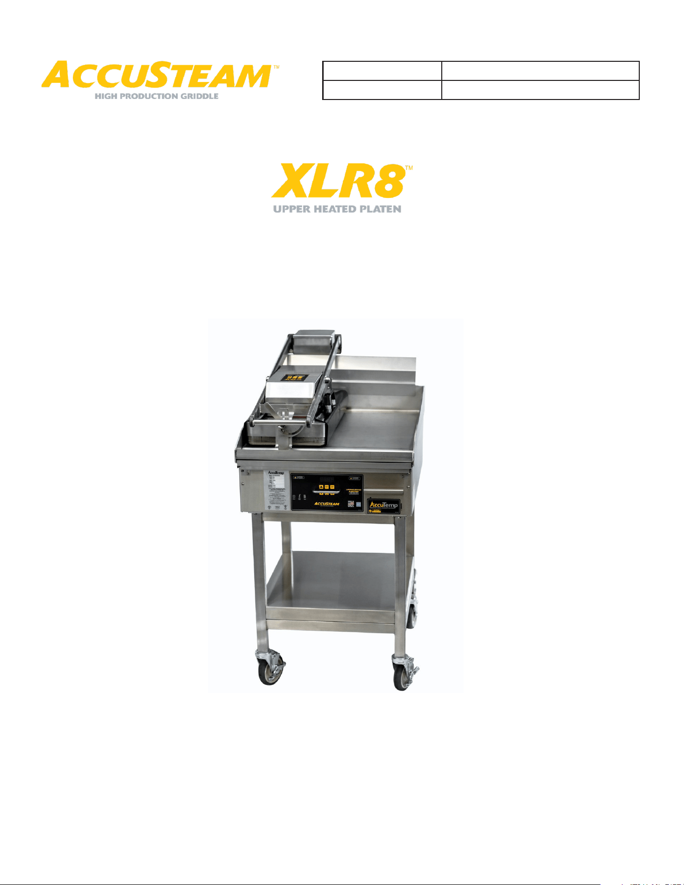
XLR8 UPPER HEATED PLATEN
INSTALLATION & OPERATOR MANUAL
Serial Number:
Model:
SP8144-2408
XLR8 Installation & Operation Manual
1
DESCRIPTION PAGE
Table of Contents / Document History 1
Safety Warnings 2
General Info 3
Installation 4
Installation - Factory Prepped Griddle 7
Installation - Field Prepped Griddle 10
Operation 19
Planned Maintenance 23
Wiring Schematic 24
Limited Warranty Statement 25
Service Information Rear Cover
TABLE OF CONTENTS
DOCUMENT HISTORY
Current Revision Date Prior Revision Date Revision
2408 08/14/2024 2011 11/15/2020 Updated: Photographs, Install instructions, Program
instructions.

SP8144-2408
XLR8 Installation & Operation Manual
2
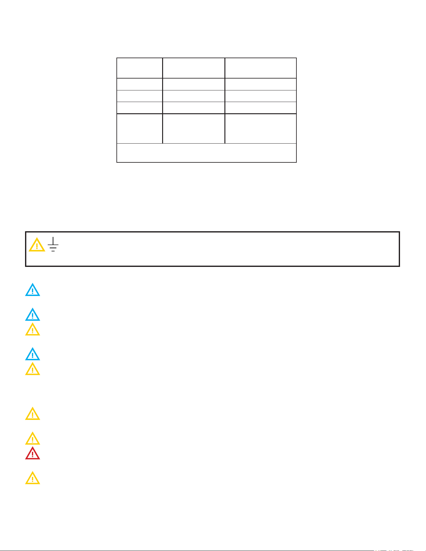
1. WARNING SYMBOL DEFINITIONS
SYMBOL DEFINITIONS
Symbols are used to attract your attention to possible dangers. They are only
eective if the operator uses proper accident prevention measures. Some of the
symbols are boxed text; while others maybe just picture icons. Please give this
information the respect they deserve for safe operation.
CAUTION -
HOT SURFACE
DANGEROUS
VOLTAGE
EARTH GROUND
DANGER
Indicates an imminently hazardous
situation; which, if unchanged, will
result in death or serious injury.
CAUTION
Indicates a potentially hazardous
situation; which, if unchanged, will
result in minor or moderate injury.
NOTE
Advises the reader of information
or instructions, vital to the
operation or maintenance of the
equipment.
In the event of a power failure, do not attempt to operate this equipment.
Improper installation, adjustment, alteration, service or maintenance can cause property
damage, injury or death. Read the installation, operating, and maintenance instructions
thoroughly before installing or servicing this equipment.
Only qualified service technicians/electricians should install this equipment to ensure that
all electrical and safety requirements are met and that all wiring is installed in accordance
with all national, state and local electrical codes.
WARNING
WARNING
WARNING
SP8144-2408
XLR8 Installation & Operation Manual
3
2. General Information
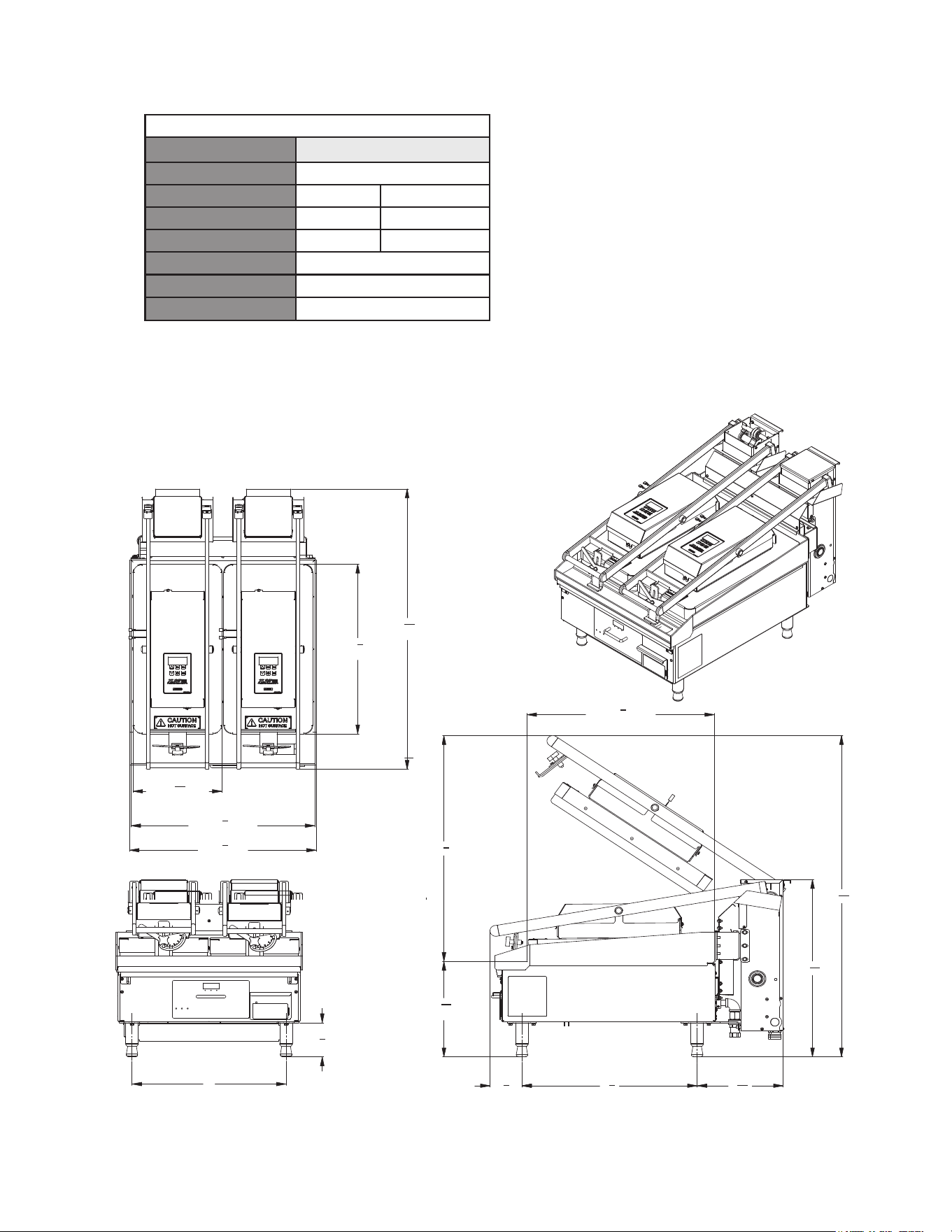
2.1 Unit Specifications
MM5261-2408
AccuTemp Products, Inc.
800-210-5907 | accutemp.net
®
AccuTemp product may be covered by one or more US Patents. See www.accutempip.net
XLR8™ UPPER HEATED PLATEN
Electric Upper Heated Platen Arm
Drawing shown with (2) XLR8 Upper Heated Arms and Required Leg Stabilization Kit.
Required mounting bracket illustrated.
Available in 2’, 3’ or 4’. Electric kits come with
grease sheild and clips while gas kit comes with
flue draft diverter.
24
3
8
"
(COOKING DEPTH)
20"
4
3
4
"
1
"31
2
"
4
22
3
"
8
4
1
"
16
11
3
"
16
11
24
(COOKING HEIGHT)
"
5
16
13
44
13
16
"
9
(PLATEN WIDTH)
16
11 "
(UNIT DEPTH)
"39
16
1
(UNIT WIDTH)
"24
4
1
(COOKING WIDTH)
"23
8
7
23
5
8
"
(PLATEN DEPTH)
24
3
8
"
(COOKING DEPTH)
20"
4
3
4
"
1
"31
2
"
4
22
3
"
8
4
1
"
16
11
3
"
16
11
24
(COOKING HEIGHT)
"
5
16
13
44
13
16
"
9
(PLATEN WIDTH)
16
11 "
(UNIT DEPTH)
"39
16
1
(UNIT WIDTH)
"24
4
1
(COOKING WIDTH)
"23
8
7
23
5
8
"
(PLATEN DEPTH)
24
3
8
"
(COOKING DEPTH)
20"
4
3
4
"
1
"31
2
"
4
22
3
"
8
4
1
"
16
11
3
"
16
11
24
(COOKING HEIGHT)
"
5
16
13
44
13
16
"
9
(PLATEN WIDTH)
16
11 "
(UNIT DEPTH)
"39
16
1
(UNIT WIDTH)
"24
4
1
(COOKING WIDTH)
"23
8
7
23
5
8
"
(PLATEN DEPTH)
24
3
8
"
(COOKING DEPTH)
20"
4
3
4
"
1
"31
2
"
4
22
3
"
8
4
1
"
16
11
3
"
16
11
24
(COOKING HEIGHT)
"
5
16
13
44
13
16
"
9
(PLATEN WIDTH)
16
11 "
(UNIT DEPTH)
"39
16
1
(UNIT WIDTH)
"24
4
1
(COOKING WIDTH)
"23
8
7
23
5
8
"
(PLATEN DEPTH)
XLR8 Upper Heated Platen
Model #
XLR82401B-00
Phase 1
Volts 208 V 240 V
Amps 10 A 11.2 A
Watts 2.1 kW 2.7 kW
Breaker Size 15A
NEMA Plus (208/240) L6-30P
Unit Width (one arm) 11 9/16”
Notes:
1. Each XLR8™ Arm comes with 6’
power cord, separate receptacle
needed for each unit.
2. For use on individual branch
circuit only.
3. Only 2 XLR8 arms can be
mounted per griddle.
MM5261-2408
AccuTemp Products, Inc.
800-210-5907 | accutemp.net
®
AccuTemp product may be covered by one or more US Patents. See www.accutempip.net
XLR8™ UPPER HEATED PLATEN
Electric Upper Heated Platen Arm
Drawing shown with (2) XLR8 Upper Heated Arms and Required Leg Stabilization Kit.
Required mounting bracket illustrated.
Available in 2’, 3’ or 4’. Electric kits come with
grease sheild and clips while gas kit comes with
flue draft diverter.
24
3
8
"
(COOKING DEPTH)
20"
4
3
4
"
1
"31
2
"
4
22
3
"
8
4
1
"
16
11
3
"
16
11
24
(COOKING HEIGHT)
"
5
16
13
44
13
16
"
9
(PLATEN WIDTH)
16
11 "
(UNIT DEPTH)
"39
16
1
(UNIT WIDTH)
"24
4
1
(COOKING WIDTH)
"23
8
7
23
5
8
"
(PLATEN DEPTH)
24
3
8
"
(COOKING DEPTH)
20"
4
3
4
"
1
"31
2
"
4
22
3
"
8
4
1
"
16
11
3
"
16
11
24
(COOKING HEIGHT)
"
5
16
13
44
13
16
"
9
(PLATEN WIDTH)
16
11 "
(UNIT DEPTH)
"39
16
1
(UNIT WIDTH)
"24
4
1
(COOKING WIDTH)
"23
8
7
23
5
8
"
(PLATEN DEPTH)
24
3
8
"
(COOKING DEPTH)
20"
4
3
4
"
1
"
31
2
"
4
22
3
"
8
4
1
"
16
11
3
"
16
11
24
(COOKING HEIGHT)
"
5
16
13
44
13
16
"
9
(PLATEN WIDTH)
16
11 "
(UNIT DEPTH)
"39
16
1
(UNIT WIDTH)
"24
4
1
(COOKING WIDTH)
"23
8
7
23
5
8
"
(PLATEN DEPTH)
24
3
8
"
(COOKING DEPTH)
20"
4
3
4
"
1
"31
2
"
4
22
3
"
8
4
1
"
16
11
3
"
16
11
24
(COOKING HEIGHT)
"
5
16
13
44
13
16
"
9
(PLATEN WIDTH)
16
11 "
(UNIT DEPTH)
"39
16
1
(UNIT WIDTH)
"24
4
1
(COOKING WIDTH)
"23
8
7
23
5
8
"
(PLATEN DEPTH)
XLR8 Upper Heated Platen
Model #
XLR82401B-00
Phase 1
Volts 208 V 240 V
Amps 10 A 11.2 A
Watts 2.1 kW 2.7 kW
Breaker Size 15A
NEMA Plus (208/240) L6-30P
Unit Width (one arm) 11 9/16”
Notes:
1. Each XLR8™ Arm comes with 6’
power cord, separate receptacle
needed for each unit.
2. For use on individual branch
circuit only.
3. Only 2 XLR8 arms can be
mounted per griddle.

SP8144-2408
XLR8 Installation & Operation Manual
4
3. INSTALLATION
TOOLS REQUIRED:
Standard socket set up to 3/4”
Standard Wrench set up to 3/4”
Standard Hex (allen) Wrench set up to 1/2”
1/2” Drive Ratchet
#2 Phillips and #2 standard screwdrivers
90 degree angled #2 Phillips Screwdriver
Torque wrench with inch/lbs or feet/lbs
measurement.
Level
Digital Clamp Ammeter
Multimeter
Weighted Temperature Probe
Digital Temperature Meter
3.1 INSTALLATION NOTICE
Only qualified service technicians/electricians should perform the installation to ensure
that all electrical and safety requirements are met and that all wiring installations are
performed in accordance with all national, state and local codes.
3.2 UNPACKING
This equipment was carefully inspected before shipment from the factory. The transportation
company assumes full responsibility for safe delivery to the customer until customer acceptance
of the package. Careful inspection of the packaging and the equipment should be completed
before acceptance from the transportation company.
3.3 XLR8 LIFTING
The equipment is heavy enough to require additional manpower or powered assistance when
installing or moving.
When moving the equipment manually make sure there are enough people for the task as the
equipment is heavy.
Make sure the equipment is not dropped during moving. People doing the carrying could
be seriously injured and/or the equipment damaged. The manufacturer does not accept any
responsibility for damage resulted from such actions.
3.4 LOCATION AND PLACEMENT
The XLR8 electric equipment has been designed to be mounted on an AccuTemp Accusteam
griddle.
The operating temperature ranges from 150°- 440°F (93°- 204°C). Since these temperatures can
also be found on surfaces around the perimeter of this commercial equipment, care should be
given not to install next to or against, objects or surfaces with a low melting or flash point.
SP8144-2408
XLR8 Installation & Operation Manual
5
Location
Combustible
Construction
Non-Combustible
Construction
Back
2 Inches 0 inches
Right Side
1 Inch 0 inches
Left Side
1 inch 0 inches
Above
Arms
26 inches
(+height of
griddle)
26 inches (+height
of griddle)
SUITABLE FOR ALL INSTALLATION ON COMBUSTIBLE
FLOORS.
3.5 CLEARANCES
3.6 LEVELING
The XLR8 must be installed level to the griddle surface. An out-of-level condition Can result in
uneven cooking.
3.7 ELECTRICAL CONNECTIONS
This commercial equipment must be properly grounded in accordance of all current
National, state and local codes. Never remove the ground prong of the plug.
3.7.1 ELECTRICAL SUPPLY
The electrical voltage requirement is listed on the data plate that is located on the lower left
side panel.
Make sure the voltage is within 10% of the voltage listed on the steamer data plate.
Connection to any other voltage not identified on the data plate will cause damage to the
components and is not covered under warranty.
Grounding provides a path for electric current to reduce risk of shock.
If provided with one, the plug must be plugged into a receptacle that is properly installed and
grounded in accordance with all National, State and local electrical codes or in the absence of
local electrical codes with the National Electric Code, ANSI/NFPA 70, or the Canadian Code, CSA
C22.2 as applicable.
Under no circumstances shall the plugs grounding prong be cut or bent to fit a receptacle
other than the one specified.
Do not use any adapters.
Any in-field modification made that bypass the safety features of this equipment will result in
serious injury or death.
Any in-field modifications made without written authorization from AccuTemp Products, Inc.
will void all written and oral warranties.

SP8144-2408
XLR8 Installation & Operation Manual
6
The XLR8 has been designed, manufactured and tested to meet or exceed the demanding
standards of safety set forth by ANSI/NFPA 70. To to ensure that this high level of safety is
maintained in your installation, it is important that you read and understand the following
information before attempting to use the equipment.
3.7.2 ELECTRICAL REQUIREMENTS
Electrical requirements are listed on the data plate located on the side of the tower. The supplied
cord and the appropriate UL listed plug must be connected to the correct voltage specified on the
units data tag. Make sure that the voltage at your supply receptacle is within ± 10 % of the voltage
listed on the griddle data tag. Connection to any other voltage may cause damage to components
in the commercial equipment. The equipment plug must be used with the appropriate receptacle.
3.7.3 GROUNDING INSTRUCTIONS
Grounding provides a path for electric current to reduce the risk of shock. This product is
equipped with a power cord having a grounding conductor and a grounding plug. The plug must
be plugged into a grounded receptacle that is installed and grounded in accordance with local
codes, or in the absence of local codes, with the National Electric Code, NFPA 70, or the Canadian
Electrical Code, CSA22.2, as applicable
SP8144-2408
XLR8 Installation & Operation Manual
7
3.8 INSTALL PROCESS - MOUNTING BRACKETS - FACTORY PREPPED GRIDDLE
3.8.1 MOUNTING BRACKET PARTS
Ensure all hardware is present before beginning installation.
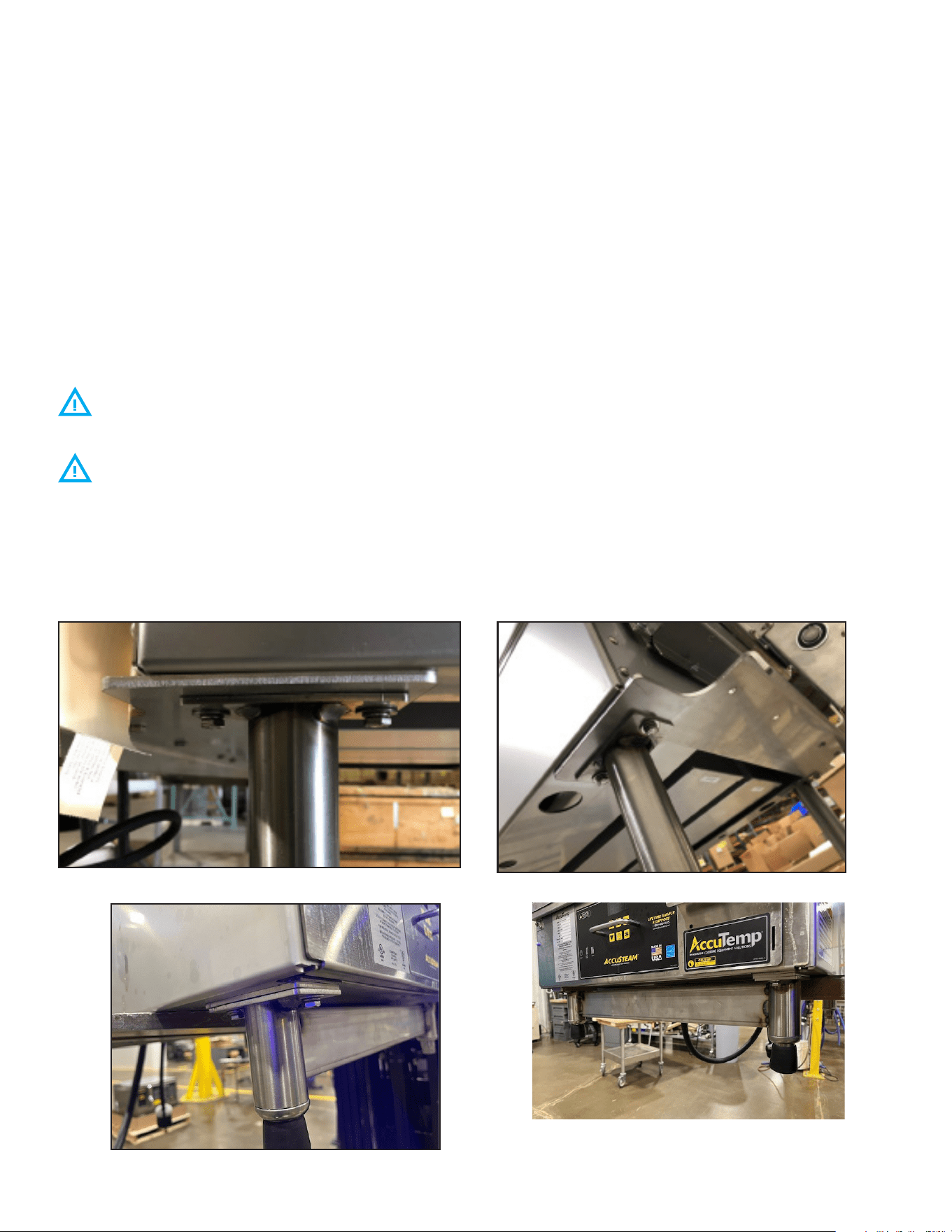
A countertop griddle prepped for XLR8 from the factory will have the tower assembly base
and rear bracket (Figure 1 & 2), front spacers and leg stabilization (Figure 3 & 4) kits pre-installed.
A griddle due to be or already installed on a stand will require removing the legs to install the
FRONT SPACERS and TOWER ASSEMBLY BASE BRACKET (Figure 1 & 2).
Figure 1
Figure 2
Figure 3
Figure 4
ATTENTION
The following instructions apply for griddles that have been
factory prepped to accommodate the XLR8 upper heated platen.
The front stabilization bracket and the rear mounting brackets
have been installed at the factory.
SP8144-2408
XLR8 Installation & Operation Manual
8
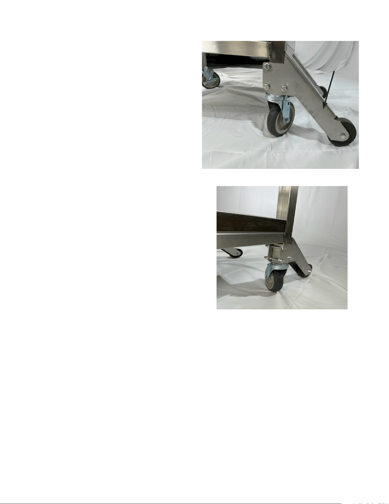
3.8.2 STAND REAR BRACE INSTALLATION INSTRUCTIONS
1. Secure the wheel (if not attached) to the
brace using 1 x screw and 1 x nut. One
wheel to each brace. Do not overtighten!
Wheel must be able to turn freely.
2. Attach the braces to the rear legs of
the stand, threads inboard. Tighten to
240inlbs/20ftlbs.
BRACE
Figure 5
Figure 6
SP8144-2408
XLR8 Installation & Operation Manual
9
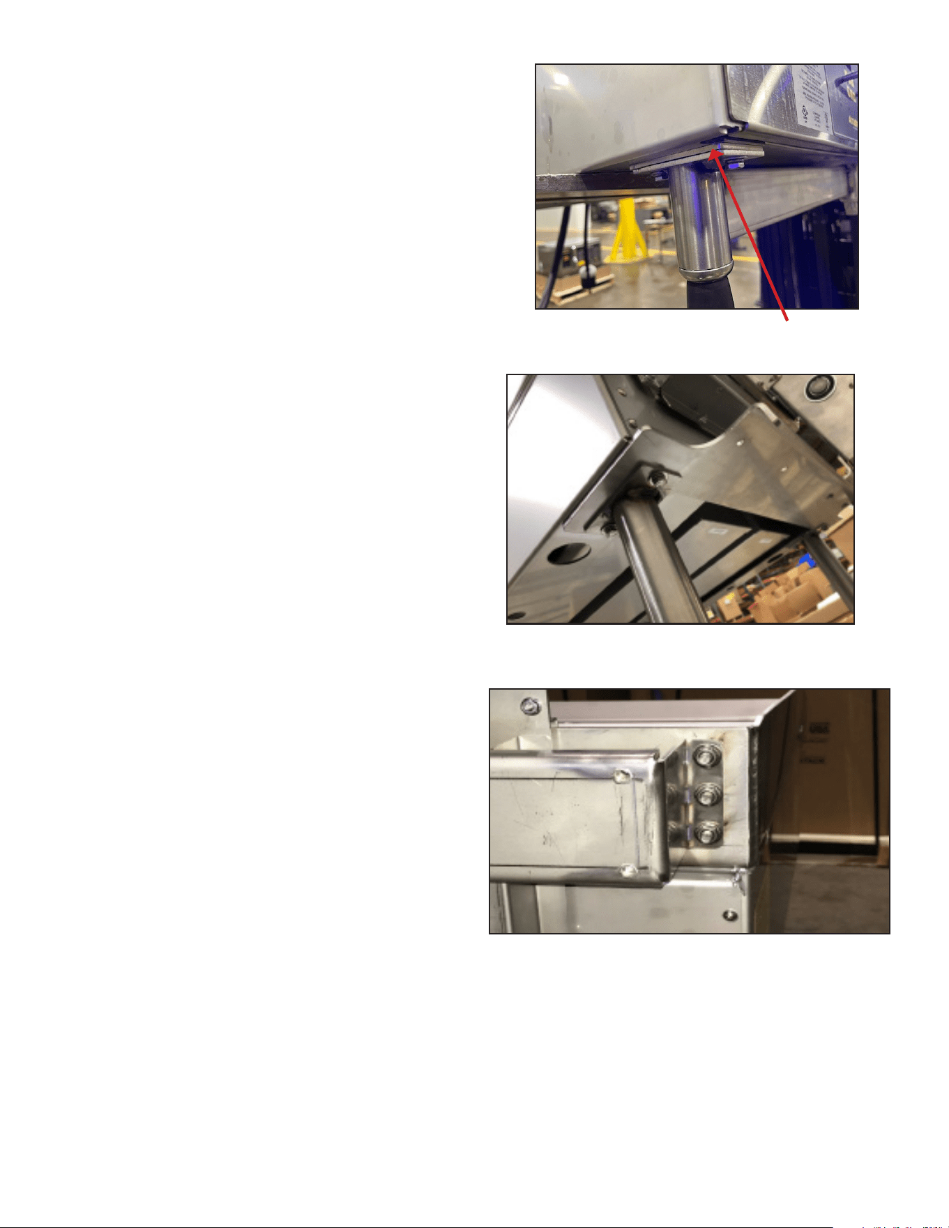
3.8.3 STAND MOUNTING INSTRUCTIONS
1. Install griddle on stand per instructions
in the griddle installation & operator
manual. Loosely secure hardware. Remove
necessary hardware to install one bracket
at a time per the following steps.
A. Insert the front spacers between the
mounting holes on the griddle and the
stand (Figure 7) and secure hardware.
Figure 9
2. Install the tower assembly rear bracket to
the six studs on the rear backsplash of the
griddle (Figure 9).
B. Line up the tower base bracket with the
rear griddle mounting holes (Figure 8) and
secure using 1” x 1/4” hardware. Tighten
to 75inlbs or 6.25 ftlbs
Figure 7
Figure 8
Front Spacer
SP8144-2408
XLR8 Installation & Operation Manual
10
3.9 INSTALL PROCESS - MOUNTING BRACKETS - FIELD ASSEMBLED GRIDDLE
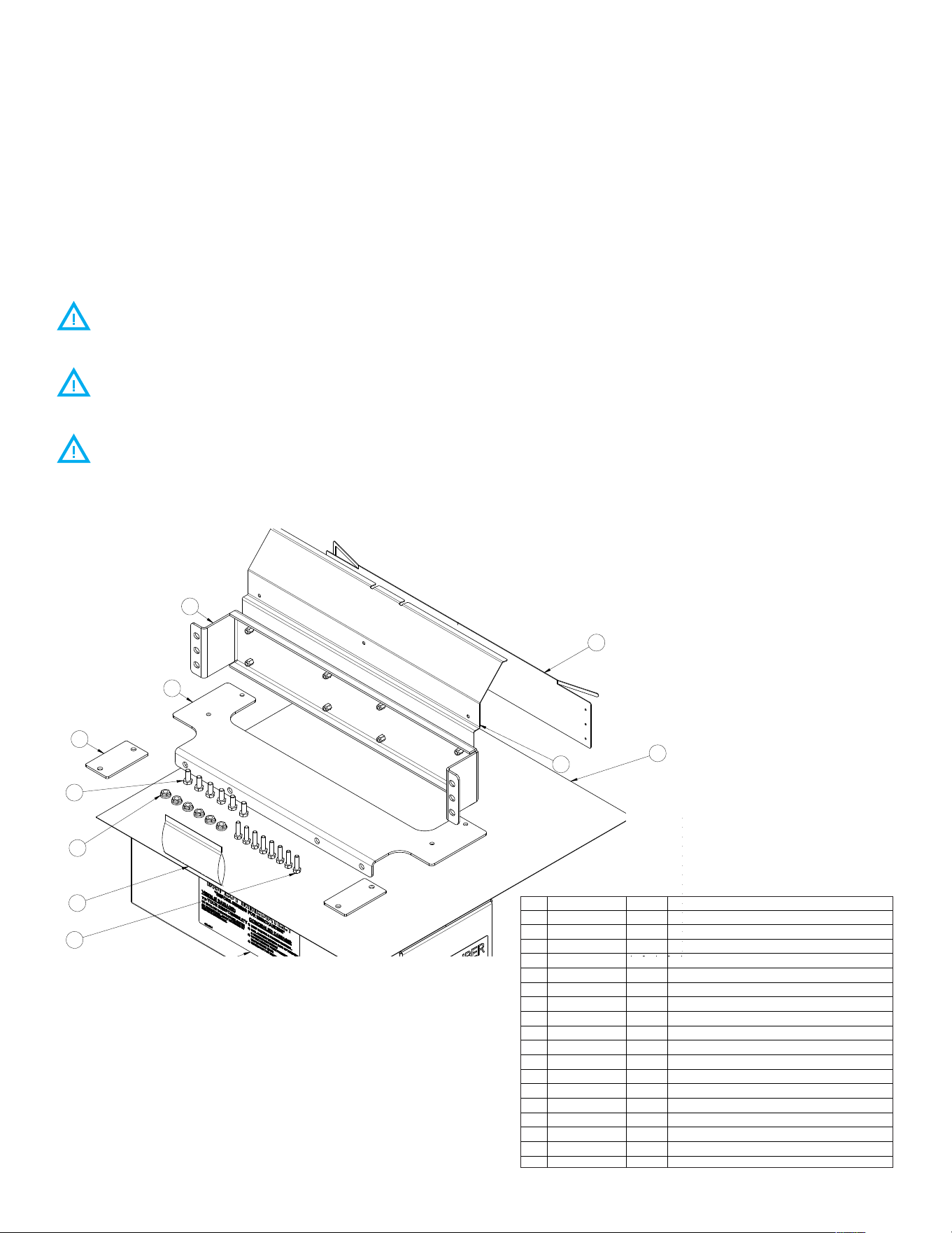
3.9.1 MOUNTING BRACKET PARTS
Ensure all hardware is present before beginning installation.
A griddle already installed on LEGS will require seperating from the legs to install the FRONT
STABILIZER and TOWER ASSEMBLY BASE BRACKET.
A griddle due to be or already installed on a STAND will require seperating from the stand to
install the FRONT SPACERS and TOWER ASSEMBLY BASE BRACKET.
Prior to installing the XLR8 accessory, the griddle backsplash with need preparing.
Unless otherwise specified,
Dimensions: Inches
Bends: 90
Tolerances:
Angular 1°
2 Place Decimal .02
3 Place Decimal .005
T.I.R .005
√125 Micro Inches
GD&T Per ANSI Y14.5M
INDICATED EDGES
MUST BE SOFTENED:
* = NEAR SIDE
* = FAR SIDE
* = BOTH SIDES
Scale: 1:2
ECN:
F
G
J
B
Monday, August 19, 2024 2:31:16 PM
11 5 39 27
D
12 10 8 6 4 1
4681012 7 29 3511
A
C
E
H
K
K
H
E
C
A
D
B
J
G
F
A
KIT, MOUNTING, XLR8
ATG
06/13/24
N/A
06/13/24
Comments:
Material:
Finish:
N/A
Do Not Scale Drawing
Proj. Engr.
SM
SM
Checked
Drawn
11/20/23
Date
Sheet 1 of 1
D
Name
Fort Wayne, IN 46825
AT2A-7089
Size: Drawing No.:
Rev:
Title:
AccuTemp Products, Inc.
8415 N. Clinton Park
RELEASED
ECN
PDM
ECO
REV DESCRIPTION DATE APPR
REVISIONS
1320 0017-05 A RELEASE TO PRODUCTION; DEV003534 06/13/24 GLS/ATG
AT2A-7089-6/
48" GAS
AT2A-7089-5/
36" GAS
AT2A-7089-4/
24" GAS
AT2A-7089-3/
48" ELECTRIC
AT2A-7089-2/
36" ELECTRIC
AT2A-7089-1/
24" ELECTRIC
PART NUMBER ITEM DESCRIPTION
2 2 2 2 2 2 AT0L-6420-2 13 PACKAGE LABEL, PRODUCT BARCODE
2 2 2 2 2 2 AT0L-4920-1 12 LABEL, FREIGHT DAMAGE
1 - - 1 - - AT2S-4882-27 11 CARTON, BOX 48 x 8 x 8
- 1 - - 1 - AT2S-4882-26 11 CARTON, BOX 36 x 8 x 8
- - 1 - - 1 AT2S-4882-25 11 CARTON, BOX 24 x 8 x 8
AR AR AR AR AR AR AT0S-2935-2 10 PACKAGING, FOAM
1 1 1 1 1 1 AT0H-2782-1 9 BAG, 3 X 5 RECLOSABLE
8 8 8 8 8 8 AT0F-2875-51081 8 SCREW, 1/4-20UNC X 1 HEX HEAD MACHINE
2 2 2 2 2 2 AT2M-7081-1 7 MOUNTING PLATE, LEG
1 - - 1 - - AT2M-7084-3 6 TEMPLATE, MARKING, XLR8
- 1 - - 1 - AT2M-7084-2 6 TEMPLATE, MARKING, XLR8
- - 1 - - 1 AT2M-7084-1 6 TEMPLATE, MARKING, XLR8
6 6 6 6 6 6 AT0F-2875-61060 5 SCREW, 5/16-18UNC X 3/4 HEX HEAD MACHINE
6 6 6 6 6 6 AT0F-1017-61001 4 NUT, 5/16-18UNC HEX SERRATED
- - - 1 - - AT2A-7088-3 3 BRACKET ASSY, DRAFT DIVERTER 48"
- - - - 1 - AT2A-7088-2 3 BRACKET ASSY, DRAFT DIVERTER 36"
- - - - - 1 AT2A-7088-1 3 BRACKET ASSY, DRAFT DIVERTER 24"
1 - - - - - AT2M-7085-3 3 BRACKET, DRAFT DIVERTER - 48"
- 1 - - - - AT2M-7085-2 3 BRACKET, DRAFT DIVERTER - 36"
- - 1 - - - AT2M-7085-1 3 BRACKET, DRAFT DIVERTER - 24"
1 - - 1 - - AT2M-7082-3 2 BRACKET, TOWER SUPPORT, BOTTOM
- 1 - - 1 - AT2M-7082-2 2 BRACKET, TOWER SUPPORT, BOTTOM
- - 1 - - 1 AT2M-7082-1 2 BRACKET, TOWER SUPPORT, BOTTOM
1 - - 1 - - AT2A-7087-3 1 BRACKET ASSY, LIFT
- 1 - - 1 - AT2A-7087-2 1 BRACKET ASSY, LIFT
- - 1 - - 1 AT2A-7087-1 1 BRACKET ASSY, LIFT
13
10
11
7
2
1
9
4
6
8
3
5
AT2A-7089-4 SHOWN
12
Unless otherwise specified,
Dimensions: Inches
Bends: 90
Tolerances:
Angular 1°
2 Place Decimal .02
3 Place Decimal .005
T.I.R .005
√125 Micro Inches
GD&T Per ANSI Y14.5M
INDICATED EDGES
MUST BE SOFTENED:
* = NEAR SIDE
*
= FAR SIDE
*
= BOTH SIDES
Scale: 1:2
ECN:
F
G
J
B
Monday, August 19, 2024 2:31:16 PM
11 5 39 27
D
12 10 8 6 4 1
4681012 7 29 3511
A
C
E
H
K
K
H
E
C
A
D
B
J
G
F
A
KIT, MOUNTING, XLR8
ATG
06/13/24
N/A
06/13/24
Comments:
Material:
Finish:
N/A
Do Not Scale Drawing
Proj. Engr.
SM
SM
Checked
Drawn
11/20/23
Date
Sheet 1 of 1
D
Name
Fort Wayne, IN 46825
AT2A-7089
Size: Drawing No.:
Rev:
Title:
AccuTemp Products, Inc.
8415 N. Clinton Park
RELEASED
ECN
PDM
ECO
REV DESCRIPTION DATE APPR
REVISIONS
1320 0017-05 A RELEASE TO PRODUCTION; DEV003534 06/13/24 GLS/ATG
AT2A-7089-6/
48" GAS
AT2A-7089-5/
36" GAS
AT2A-7089-4/
24" GAS
AT2A-7089-3/
48" ELECTRIC
AT2A-7089-2/
36" ELECTRIC
AT2A-7089-1/
24" ELECTRIC
PART NUMBER ITEM DESCRIPTION
2 2 2 2 2 2 AT0L-6420-2 13 PACKAGE LABEL, PRODUCT BARCODE
2 2 2 2 2 2 AT0L-4920-1 12 LABEL, FREIGHT DAMAGE
1 - - 1 - - AT2S-4882-27 11 CARTON, BOX 48 x 8 x 8
- 1 - - 1 - AT2S-4882-26 11 CARTON, BOX 36 x 8 x 8
- - 1 - - 1 AT2S-4882-25 11 CARTON, BOX 24 x 8 x 8
AR AR AR AR AR AR AT0S-2935-2 10 PACKAGING, FOAM
1 1 1 1 1 1 AT0H-2782-1 9 BAG, 3 X 5 RECLOSABLE
8 8 8 8 8 8 AT0F-2875-51081 8 SCREW, 1/4-20UNC X 1 HEX HEAD MACHINE
2 2 2 2 2 2 AT2M-7081-1 7 MOUNTING PLATE, LEG
1 - - 1 - - AT2M-7084-3 6 TEMPLATE, MARKING, XLR8
- 1 - - 1 - AT2M-7084-2 6 TEMPLATE, MARKING, XLR8
- - 1 - - 1 AT2M-7084-1 6 TEMPLATE, MARKING, XLR8
6 6 6 6 6 6 AT0F-2875-61060 5 SCREW, 5/16-18UNC X 3/4 HEX HEAD MACHINE
6 6 6 6 6 6 AT0F-1017-61001 4 NUT, 5/16-18UNC HEX SERRATED
- - - 1 - - AT2A-7088-3 3 BRACKET ASSY, DRAFT DIVERTER 48"
- - - - 1 - AT2A-7088-2 3 BRACKET ASSY, DRAFT DIVERTER 36"
- - - - - 1 AT2A-7088-1 3 BRACKET ASSY, DRAFT DIVERTER 24"
1 - - - - - AT2M-7085-3 3 BRACKET, DRAFT DIVERTER - 48"
- 1 - - - - AT2M-7085-2 3 BRACKET, DRAFT DIVERTER - 36"
- - 1 - - - AT2M-7085-1 3 BRACKET, DRAFT DIVERTER - 24"
1 - - 1 - - AT2M-7082-3 2 BRACKET, TOWER SUPPORT, BOTTOM
- 1 - - 1 - AT2M-7082-2 2 BRACKET, TOWER SUPPORT, BOTTOM
- - 1 - - 1 AT2M-7082-1 2 BRACKET, TOWER SUPPORT, BOTTOM
1 - - 1 - - AT2A-7087-3 1 BRACKET ASSY, LIFT
- 1 - - 1 - AT2A-7087-2 1 BRACKET ASSY, LIFT
- - 1 - - 1 AT2A-7087-1 1 BRACKET ASSY, LIFT
13
10
11
7
2
1
9
4
6
8
3
5
AT2A-7089-4 SHOWN
12
ATTENTION
The following instructions pertain to griddles being modified in
the field to accommodate the XLR8.
SP8144-2408
XLR8 Installation & Operation Manual
11
3.9.2 GRIDDLE BACKSPLASH PREPARATION
1. Ensure template received is the correct size for the width of the griddle. The template should
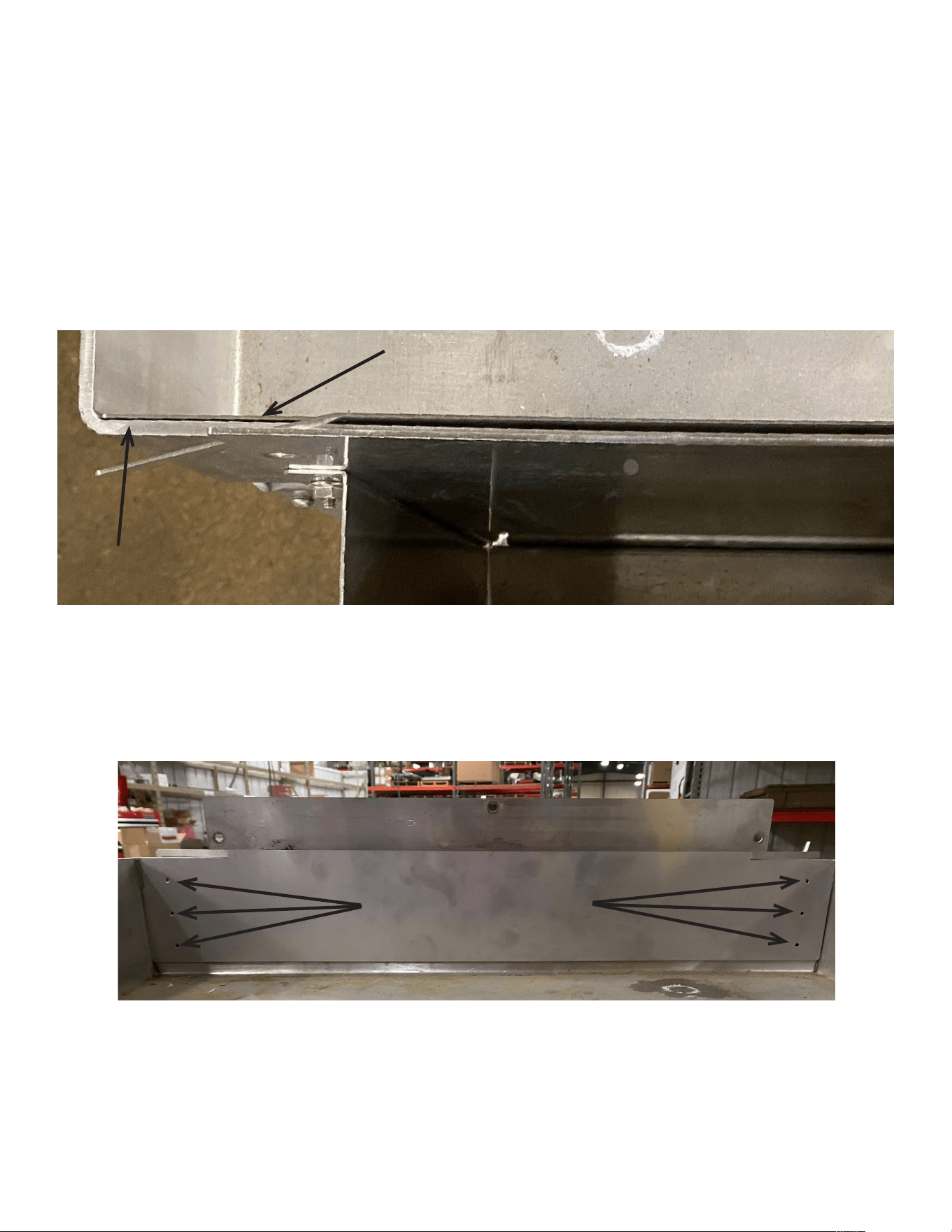
be placed so that it sits flush with the rear backsplash (Figure 10) of the griddle and should
touch both the left and right side splashes (Figure 11). For extra security C clamps can be used
to hold the template flush.
2. Use the 6 guide holes on the template to start pilot holes in the griddle backsplash (Figure 11)
using a drill bit of sucient hardness for use with 304 stainless steel.
3. Drill final holes using a 17/64th drill bit.
4. Continue drilling slowly through the griddle backsplash, using cutting fluid as needed.
5. After 6 holes have been drilled, template can be removed from the backsplash.
6 guide holes on template
XLR8 Marking Template
Griddle Backsplash
Figure 10
Figure 11
SP8144-2408
XLR8 Installation & Operation Manual
12
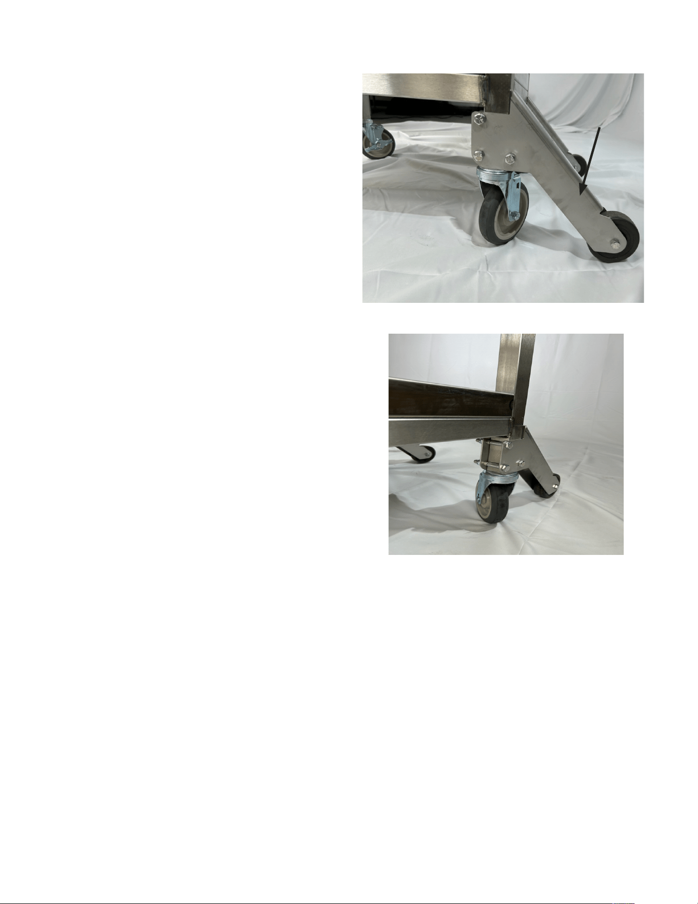
3.9.3 STAND REAR BRACE INSTALLATION INSTRUCTIONS
1. Secure the wheel (if not attached) to the
brace using 1 x screw and 1 x nut. One
wheel to each brace. Do not overtighten!
Wheel must be able to turn freely.
2. Attach the braces to the rear legs of
the stand, threads inboard. Tighten to
236inlbs/20ftlbs.
BRACE
Figure 12
Figure 13
SP8144-2408
XLR8 Installation & Operation Manual
13
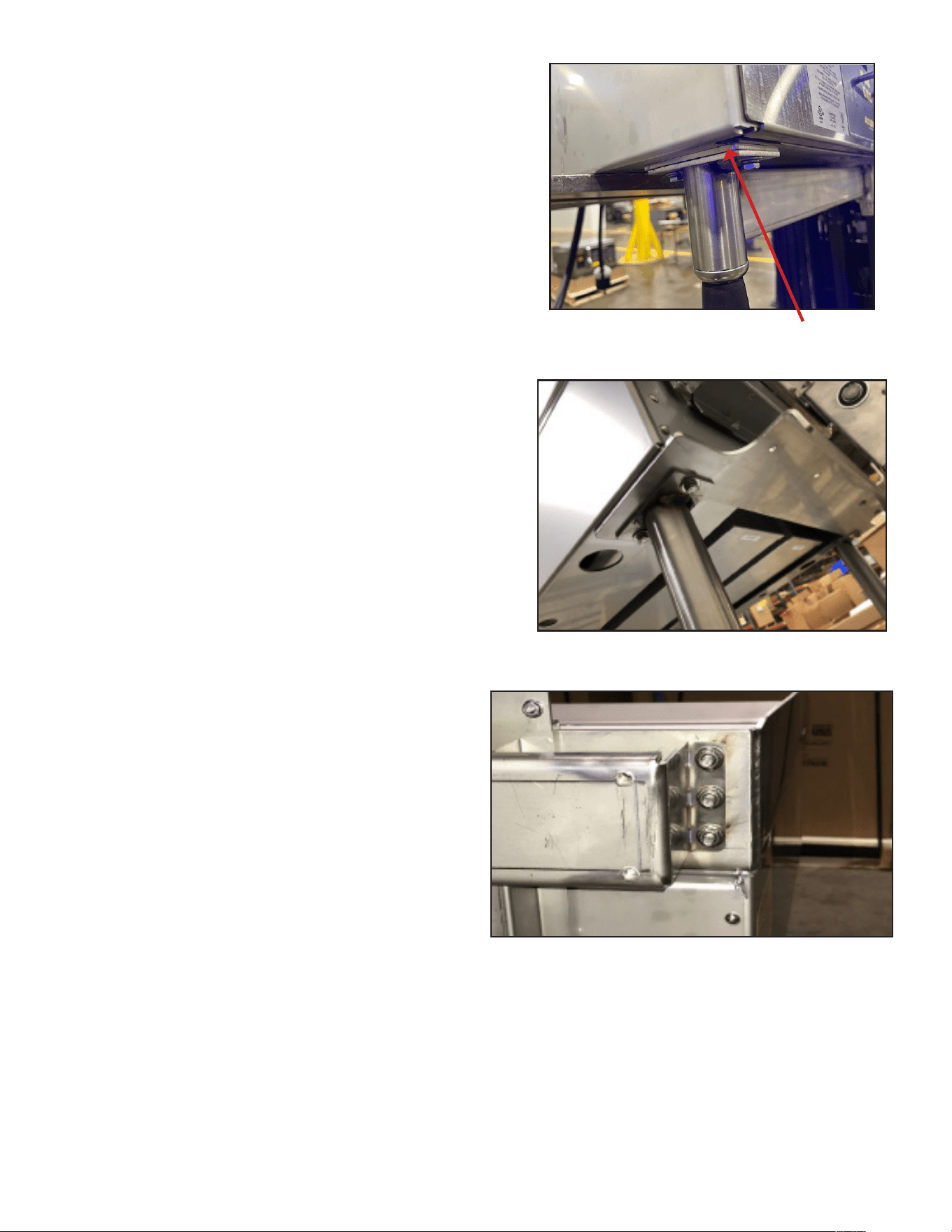
3.9.4 STAND MOUNTING INSTRUCTIONS
1. Install griddle on stand per instructions
in the griddle installation & operator
manual. Loosely secure hardware. Remove
necessary hardware to install one bracket
at a time per the following steps.
A. Insert the front spacers between the
mounting holes on the griddle and the
stand (Figure 14) and secure hardware.
Figure 14
2. Install the tower assembly rear bracket.
Thread 1 x 5/16” screws through the 6
holes made in the griddle back splash
into the rear support bracket. Secure
each screw with 5/16” serrated flange nut
(Figure 16).
B. Line up the tower base bracket with the
rear griddle mounting holes (Figure 15)
and secure hardware. Tighten to 75inlbs
or 6.25 ftlbs
Figure 15
Figure 16
Front Spacer
SP8144-2408
XLR8 Installation & Operation Manual
14
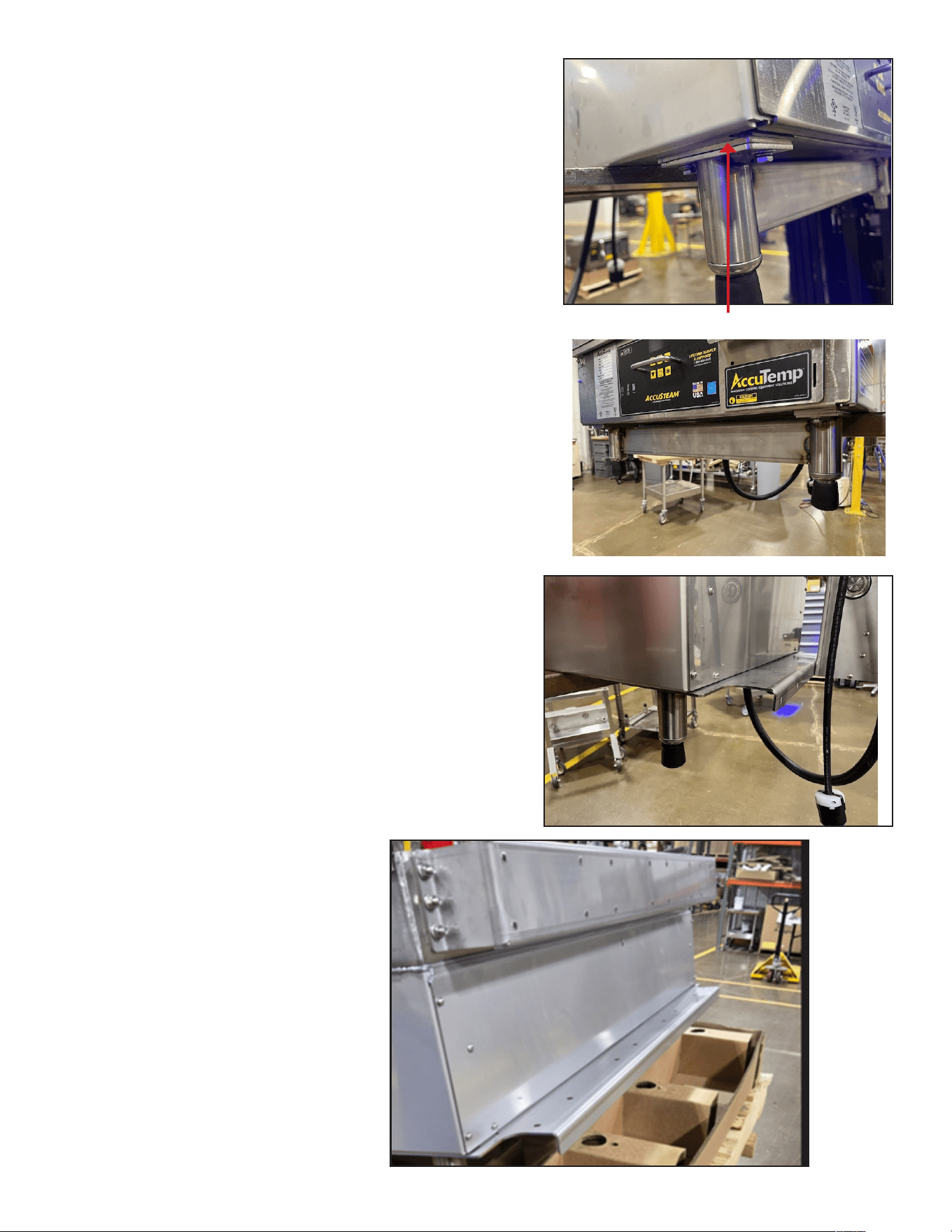
3.9.5 LEG MOUNTING INSTRUCTIONS
ATTENTION - The following instruction should be
used if the griddle is being installed on a counter-top
instead of a stand.
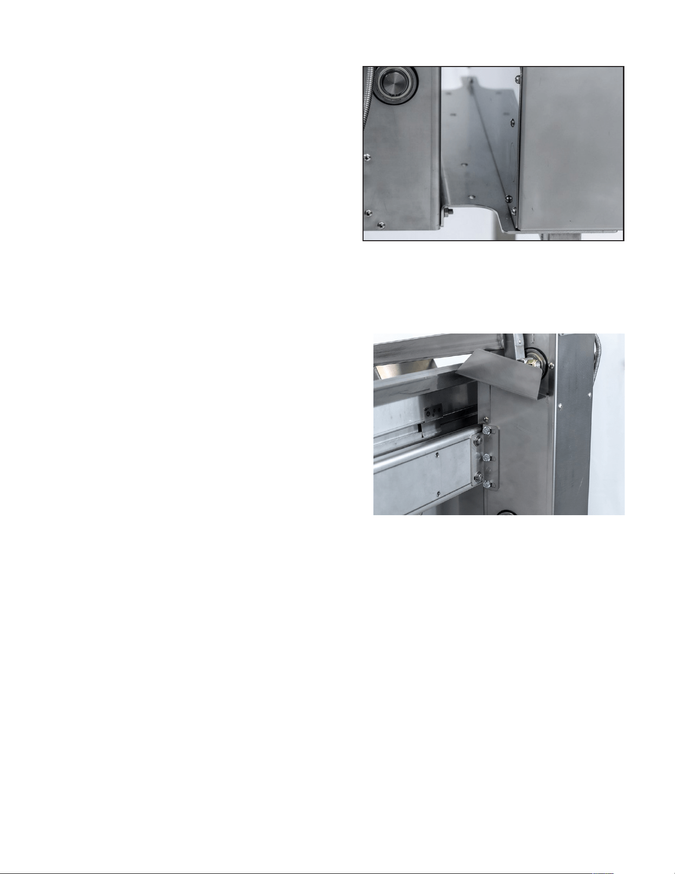
1. Install the tower base bracket, front
spacers and front leg stabilizer. It is advised
to use lift equipment at this stage to
prevent injury.
A. Lift the griddle to allow the front and rear
legs to be removed. Then insert the front
spacer between the mounting holes
on the griddle and front leg stabilizer
assembly and secure using original
hardware (Figure 17). Original single front
legs can be disposed of.
B. Insert the tower base bracket between
the rear griddle mounting holes and rear
legs and secure using original hardware
(Figure 18).
2. Install the tower assembly rear bracket.
Thread 1 x 1/4” screws through the 6 holes
made in the griddle back splash into the
rear support bracket. Secure each screw
with 6 x 5/16” nut (Figure 19).
Figure 17
Figure 18
Figure 19
Front Spacer
SP8144-2408
XLR8 Installation & Operation Manual
15
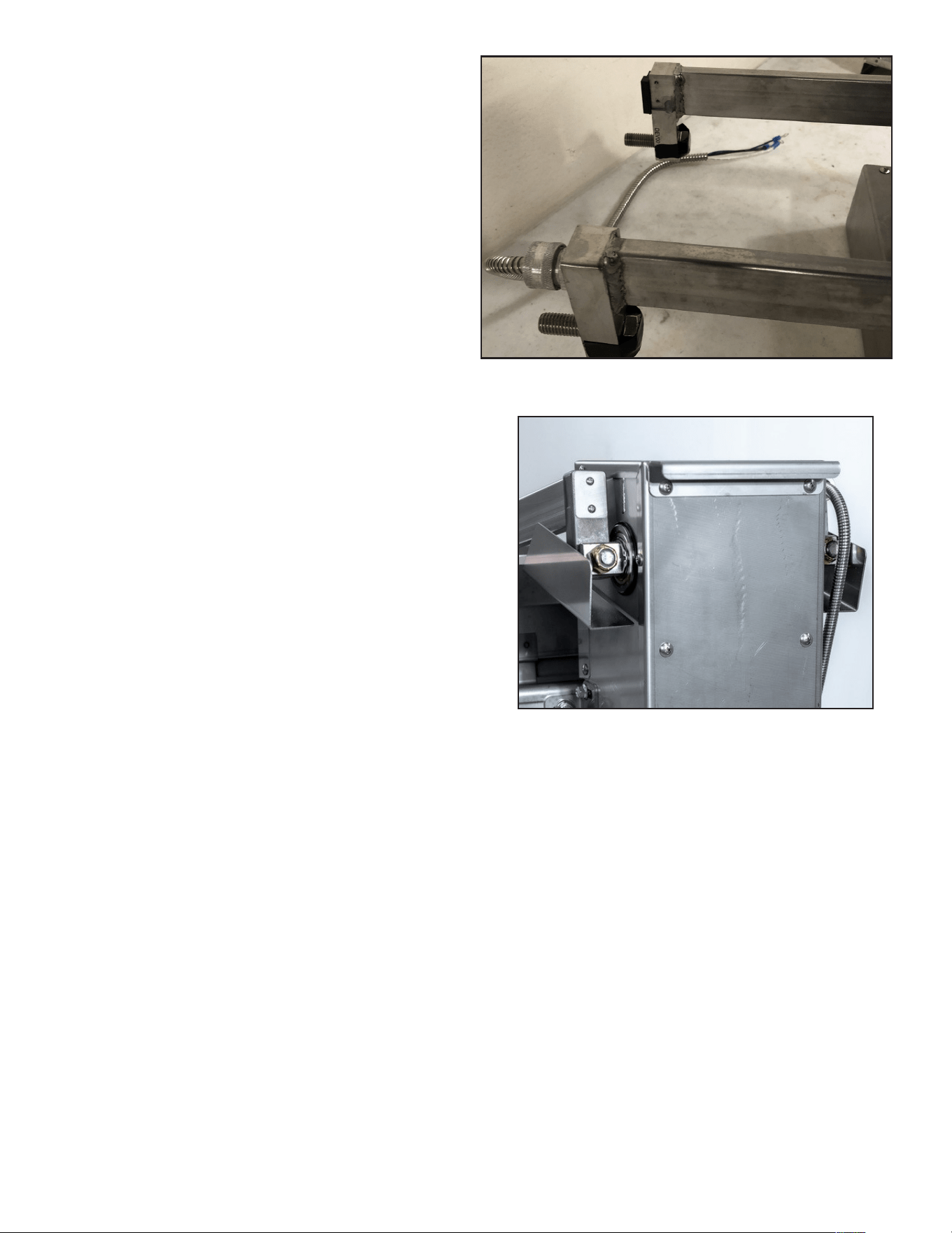
B. Align mounting bracket with the tower
assembly rear bracket and thread screws
through mounting bracket into rear
bracket (Figure 21).
C. Use serrated flange headed screws to
secure the bracket.
D. Ensure both arms are square with
the griddle. Use the griddle sides as a
reference, then snug the nuts on the
tower bottom bracket to 132 inlbs.
3.10.1 - Tower Installation
1. To mount the tower assembly to the
griddle:
A. Align the studs on the tower bottom
bracket with the holes on the tower
base bracket. Secure but do not snug
hardware to help support weight of
tower assembly (Figure 20).
3.10 TOWER AND PLATEN MOUNTING
Figure 20
Figure 21
SP8144-2408
XLR8 Installation & Operation Manual
16
3.10.2 - Platen Installation
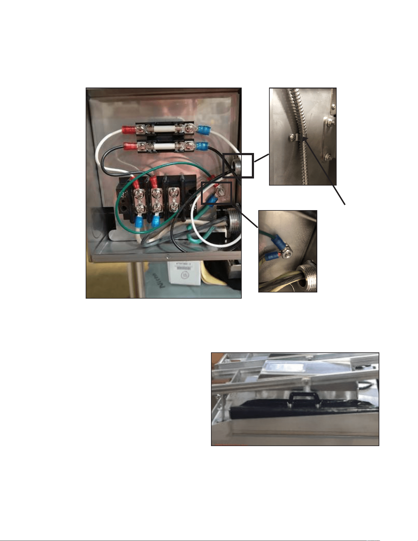
1. To mount the arm assembly to the tower
assembly:
A. Prethread the two arm mounting bolts
through the holes at the rear of the arm
assembly (Figure 22).
B. Lift the arm (requires two people) and
slide the bolts through the mounting
holes in the flattened shaft extending
from both sides near the top of the tower
assembly.
C. While one person holds the arm in place
at the highest position, the other should
secure the bolts in place using 1/2-13
nyloc nuts, tighten to 43 ftlbs. (Figure 23).
Figure 22
Figure 23
SP8144-2408
XLR8 Installation & Operation Manual
17
3.10.4 Install Teflon Sheets
5. Install the teflon sheet to the arm:
A. Raise the two teflon retension handles o
the arm. These are located on the left and
right hand side of the platen.
B. Secure one side of the teflon sheet using
one handle, keeping the handle at the
central point of the arm (Figure 25).
Stretch the teflon across the underside of the
platen and secure with the other retaining
handle.
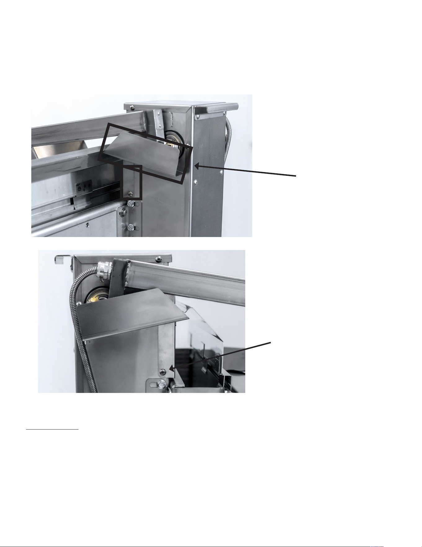
3.10.3 - Connect power cord to tower terminal
1. Remove rear sheet metal panel from tower assembly.
2. Route arm power cord through cord grip on bottom of tower assembly. Ensure there is
enough slack to connect cord ends to fuse block.
3. Secure cord to side of tower assembly using supplied spring clip and screw.
4. Connect arm power cord to upper side of terminal block (Figure 24).
Figure 24
Figure 25
Spring Clip
SP8144-2408
XLR8 Installation & Operation Manual
18
TEST INSTALL
1. Plug in tower power cord to correct NEMA receptacle.
2. Power the XLR8 on using control buttons located on top of the arm.
3. Keep arm elevated an allow to heat to temperature displayed on control digital display.
4. Monitor temperature using a wand type temperature meter.
5. Once unit has reached temperature allow 15 minutes for it to stabilize, then take three
temperature readings from the front, middle and back of the arm cooking surface.
6. The temperatures should be with 5+/-F of the temperature displayed.
3.10.5 Install Grease Shield
1. Bring arm to raised position.
2. The grease shield is secured by four phillips head screws. Identify the mounting holes on the
shield and on the tower of the XLR8, just above the mounting brackets.
3. Slot the grease shield into place under the arm, secure using screws (Figure 26 & Figure 27).
GREASE SHIELD
MOUNTING SCREW
Figure 26
Figure 27
SP8144-2408
XLR8 Installation & Operation Manual
19
4. OPERATION
RISKS RESULTING FROM CONTACT WITH VERY HOT OBJECT:
HOT
Hot areas may form during the cooking process. Use protective gloves whenever handling hot
objects.
During the cooking process, do not handle cookware containing liquids or liquid foodstus
located above eye level. Danger of burns.
Be sure all operators read, understand and follow the information contained in this manual
including caution warnings, operating instructions and safety instructions.
Never use wet or damp gloves as moisture can conduct heat quickly.
Keep the floor in front of the equipment clean and dry. If spills occur, clean immediately to
avoid potential injuries.
Do not use abrasive (or steel) materials, such as wire brushes, metal scouring pads to clean
the teflon sheet surface.
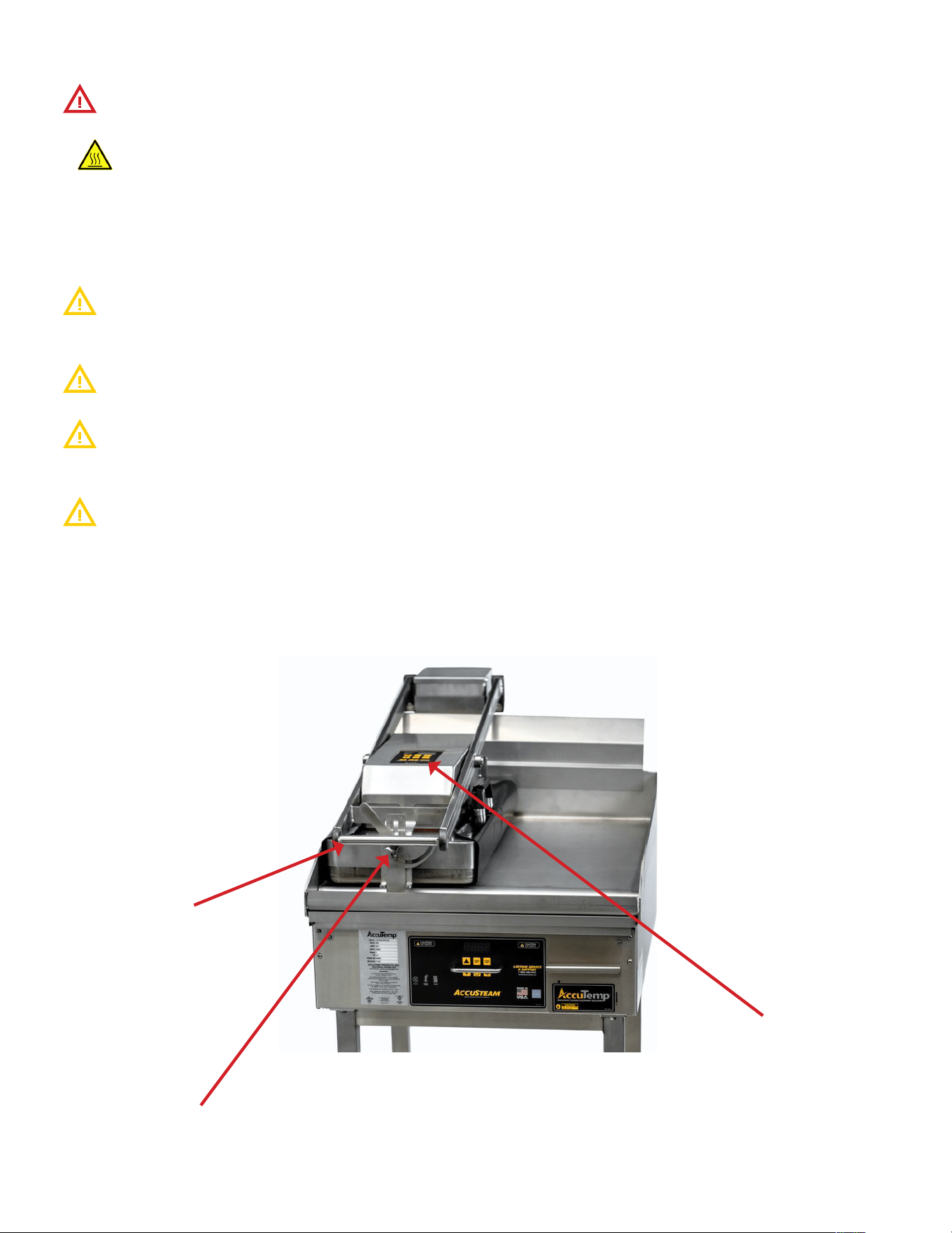
4.1 VISUAL IDENTIFICATION
Lift Handle
Height adjustment
knob
Control Panel
Figure 28
SP8144-2408
XLR8 Installation & Operation Manual
20
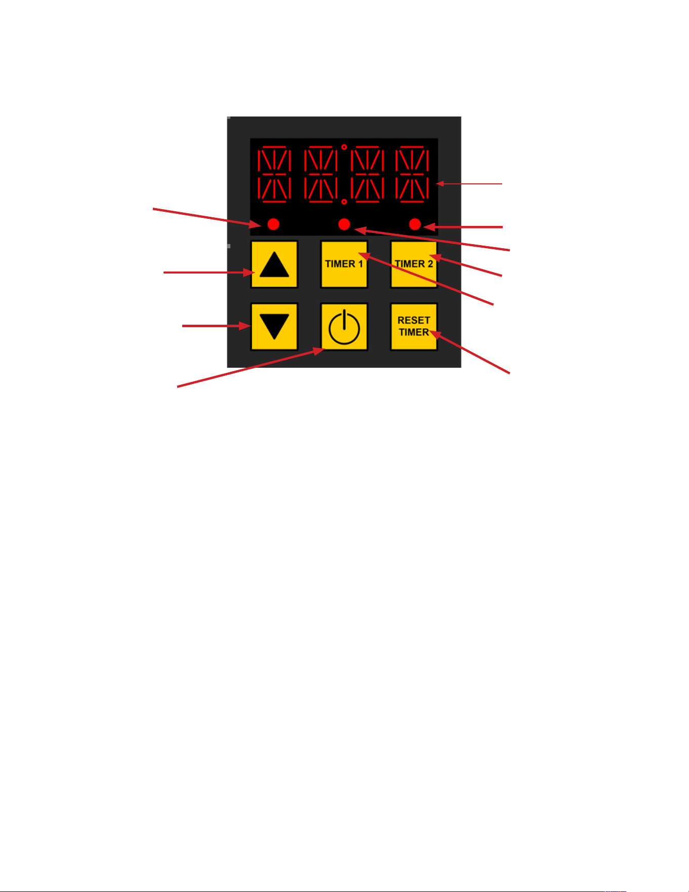
The equipment digital temperature control is easy to operate and requires little customer
interface.
OPERATOR DISPLAY AND KEYPAD
ON/OFF
KEY
PROGRAM KEY
DOWN ARROW
LED 1
TIMER 2 SET KEY
TIMER RESET KEY
LED 2
LED 3
TIMER 1 SET KEY
PROGRAM KEY
UP ARROW
OPERATOR DISPLAY
4.2 CONTROL OVERVIEW
4.2.2 SETPOINT CONTROL
The control has a single setpoint that is adjustable by the user during operation and in manager
mode. When the user adjusts the setpoint value during operation it is saved to memory. The
default setpoint is 400°F.
To adjust the set point:
1. Push the UP arrow to increase temperature and the DOWN arrow to decrease temperature.
The display will change to show the current set point.
2. Once the desired temperature has been selected, no further interaction with keys are
necessary, the unit will automatically save the selected temperature as the desired default.
4.2.3 TIMER CONTROL
Once in COOK mode, the user can select either timer 1 or timer 2 option by depressing the key.
Each timer has a two stage option. By default, each timer will be set to single stage operation (see
4.2.4 for information on programming two stage operation).
LED 2 will blink if Timer 1 is being adjusted, LED 3 will blink if timer 2 is being adjusted.
Use the UP and DOWN arrows to adjust the timer value for the selected timer. After two seconds
with no interaction, the control will automatically accept the new value.
4.2.1 PREHEAT MODE
When powered on from cold the unit will constantly display “PRE-HEAT” while the appliance
warms up.
During this mode timers are disabled. When the appliance is within 5 degrees Fahrenheit of the
setpoint the control will transition to cook mode. A timer will not begin in this state.
In Cook mode the unit will constantly display the current set point temperature.

SP8144-2408
XLR8 Installation & Operation Manual
21
4.2.4 - PROGRAMMING MODE
Manager mode allows for greater access to the XLR8 programming.
To enter Manager Mode press and hold DOWN arrow and TIMER RESET while the unit is powered
OFF. The control is now in Program Mode and LED 1, 2 and 3 will blink, and the keypad will be re-
configured as shown in the following table:
UP ARROW: Toggle between pro-
gram selection and program adjust-
ment.
TIMER 1: Save current settings and
exit manager mode
TIMER 2: Increase current displayed
programming parameters
DOWN ARROW: NOT USED POWER KEY: Exit manager mode
without saving.
TIMER RESET: Decrease current
displayed programming parameters
The following settings can be adjusted in manager mode:
PROGRAM # TEXT DISPLAY MIN VALUE MAX VALUE DEFAULT VALUE
P01 AUTO START TIMER NO YES YES
P02 TEMPERATURE SETPOINT 150F 440F 400F/204C
P03 TIMER 1 STAGE 1 VALUE 0:05 15:00 1:00
P04 TIMER 2 STAGE 2 VALUE 0:00 15:00 0:00
P05 TIMER 2 STAGE 1 VALUE 0:05 15:00 2:00
P06 TIMER 2 STAGE 2 VALUE 0:00 15:00 0:00
P07 TEMPERATURE UNIT F C F
P08 RESET TO DEFAULT NO YES NO
Any other programs displayed apart from the options listed should not be changed in any
way.
Programming Mode Example - Changing Temperature Unit setting
With the unit powered o, hold the DOWN arrow and TIMER RESET keys until P01 is displayed on
the screen.
Use the TIMER 2 button to cycle through programs until P07 is displayed.
Depress the UP arrow to enter the selected program.
Use the Timer 2 button to cycle through the program choices (in the case between F and C).
Once the chosen value is displayed, depress TIMER 1 key to save and exit. The display will power
o and the new setting is now saved to memory.
4.2.5 - USER LOCKOUT
User lockout is a hidden parameter that disables the user from changing the Timer and
Temperature setpoints from the default values. The end user will still be able to power the unit on
and select either timer 1 or timer 2.
To toggle the unit between locked/unlocked press and hold the UP arrow and TIMER 2 keys. The
unit will display LOCKED or UNLOCKED on the display and power down.
SP8144-2408
XLR8 Installation & Operation Manual
22
4.3.1 CLEAN AFTER INSTALLATION
It is recommended that you clean your XLR8 thoroughly before using it for the first time. To clean
the equipment cooking surface, just simply wash it down with a solution of mild soap and water,
then rinse thoroughly with clean water and wipe dry with a clean towel.
4.3.2 PREHEATING
Press the ON/OFF and select the desired preset. The upper platen should be approximately 40-
50F hotter than the griddle surface to achieve good caramalization on product.
The equipment will be preheated when the selected set temperature is displayed and the
corresponding LED goes solid. Please use caution as temperatures on and around the cooking
surface could cause severe burns.
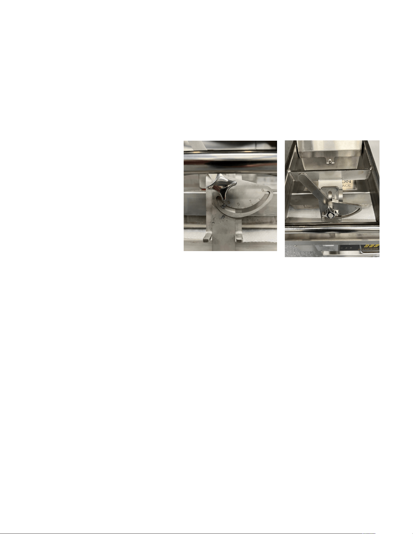
4.3.3 ADJUSTING THE PLATEN GAP
HEIGHT
The XLR8 arm has a simple mechanism
for adjusting the platen gap:
1. Turn the lock knob on the front
counter-clockwise to loosen the
height adjuster (Figure 28).
2. Use the handle on the adjuster to
raise or lower the height of the
platen. The numbers on the adjuster
are arbitrary and do not correspond
to a specific measurement.
3. Once the desired height is reached,
turn the knob counter-clockwise to
lock the platen height adjustment.
4.3.4 COOKING
If a recipe is provided for the product you are preparing, always follow your company guidelines
for preparing product.
If adjusting your own recipe to incorporate the use of the XLR8 it is recommended to apply the
following steps:
1. Divide the total cook time applied to a product cooking on just the griddle surface by half.
Adjust the time from there until you are happy with the finished product.
2. Once you have the time and temperature for the product identified, use the programming
instructions to set the timer and presets accordingly.
3. A smaller gap between platen and griddle surface will decrease cook time but may result in a
dryer product.

SP8144-2408
XLR8 Installation & Operation Manual
23
PM TASK DESCRIPTION
Daily Biannual Yearly
Verify that the equipment is level and properly located under the
hood.
X X
Verify that the temperature controller is working properly and
that there are no rips in the overlay.
X X X
Inspect the control compartment for foreign particulate and any
loose wiring or connections.
X X
Check that the power supply cord is not frayed, outer covering
is not degraded or any bare cooper is visible. Replace if required.
X X X
Verify current draw to listed current requirements on the data
tag of the equipment.
X X
Verify mounting fasteners are in place and tight. If not, correct.
If the stand has casters check that the wheels are intact and that
they are mounted correctly. If grease covered, clean with a mild
detergent and clean water. Dry completely.
X X X
After all metallic areas are cool to the touch, clean external
metal surfaces except the cooking surface. With a damp clean
towel saturated with a mild detergent and clean water. Dry with
a clean dry towel.
X X X
5. PLANNED MAINTENANCE CHECKLIST
It is recommended that you contact your AccuTemp authorized service provider to setup a planned
maintenance program to keep your equipment operating in the most ecient manner. AccuTemp
recommends a minimum of a yearly schedule.
Only qualified service technicians/electricians should perform the biannual and yearly
planned maintenance to ensure that all electrical and safety requirements are met and performed
in accordance with all national, state and local codes.
4.3.5 CLEANING
• Hold the power button for approximately 2 seconds to power unit o and allow to cool until it
is safe to touch, approximately 30 minutes.
• Remove teflon sheetand clean using mild soap and water solution and a towel.
• To clean the arm, once cooled, clean using mild soap and water solution and a towel. Rinse
when done with clean water and allow to dry overnight.
Do not Power Spray the griddle or XLR8 Upper Heated Platen. A non-Metallic cleaning pad
can be used to remove large debris or built up areas.
SP8144-2408
XLR8 Installation & Operation Manual
24
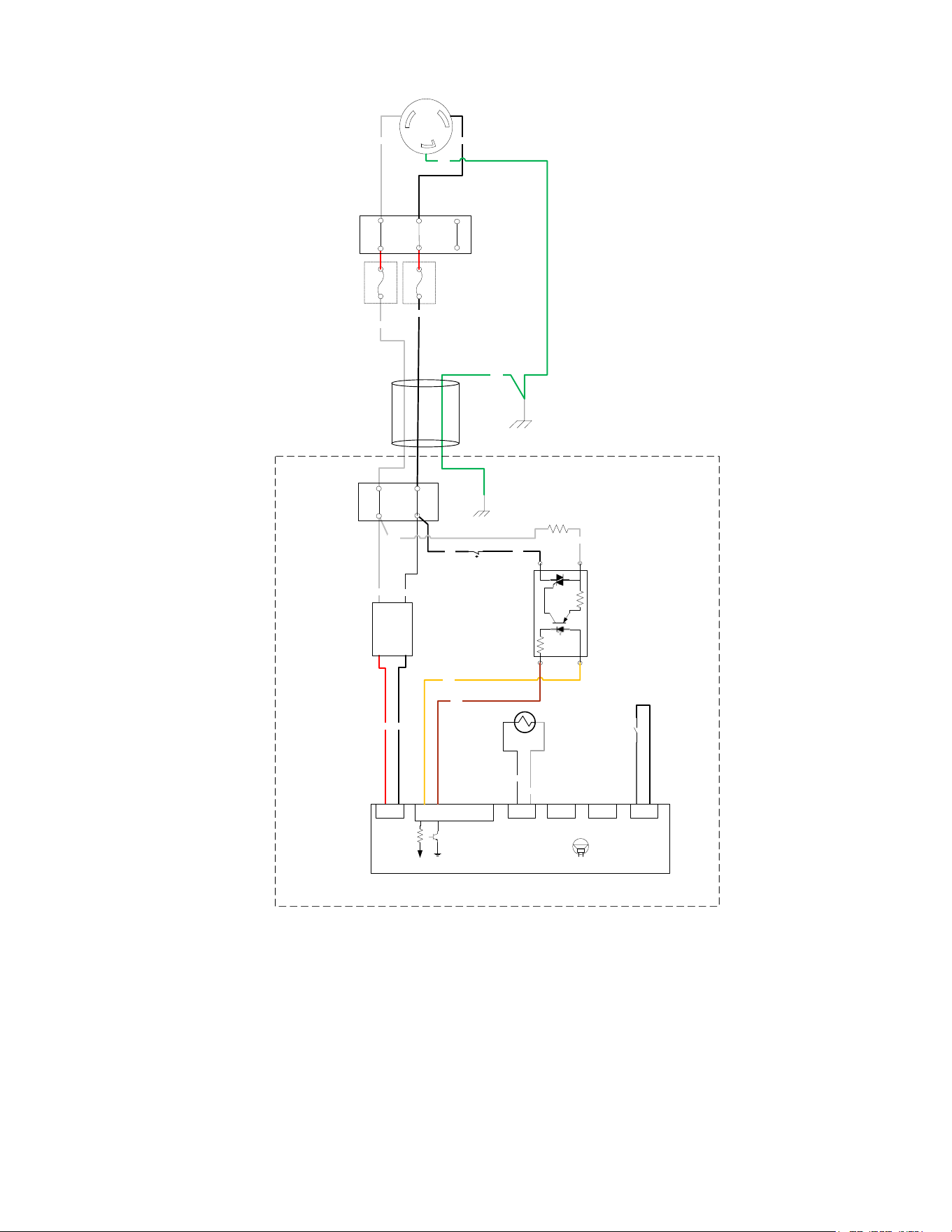
6. Wiring Schematic
Unless otherwise specified,
Dimensions: Inches
Bends: 90
Tolerances:
Angular 1°
2 Place Decimal .02
3 Place Decimal .005
T.I.R .005
√125 Micro Inches
GD&T Per ANSI Y14.5M
INDICATED EDGES
MUST BE SOFTENED:
* = NEAR SIDE
* = FAR SIDE
* = BOTH SIDES
Scale: 4:1
ECN:
F
G
J
B
Monday, July 29, 2024 1:17:39 PM
11 5 3927
D
12 10 8 6 4 1
4681012 7 293511
A
C
E
H
K
K
H
E
C
A
D
B
J
G
F
-01
SCHEMATIC, XLR8
ATG
Sheet 1 of 7
-
07/29/24
Comments:
Material:
Finish:
-
Do Not Scale Drawing
Proj. Engr.
GLS
GLS
Checked
Drawn
08/05/19
Date
07/29/24
D
Name
Fort Wayne, IN 46825
AT2T-6028
Size: Drawing No.:
Rev:
Title:
AccuTemp Products, Inc.
8415 N. Clinton Park
UNDER REVIEW
ECN PDM ECO REV DESCRIPTION DATE APPR
REVISIONS
0017-12 A RELEASE TO PRODUCTION 07/26/24 SWM/ATG
PREPRODUCTION XLR8
WHT
BLK
TOP PLATTEN
1Ø 277V
WHT
WHT
BLK
BL K
BL K
PRTD
R1
W HT
S1
AUTO START
TIMER SW
RED BL K
AC/N A C/L
85 ~305 VA C
SWITCHING
PO WER
SUPP LY
+ 12VDC -
1 2
J2
PO WER
INPUT
DIG IT AL
CONTROLLER
1 2 3 4 5 6
J7
1 2
J3
1 2
J5
2 3
J4
INPU T 1
INPUT 2 INPUT 3
OU T PUT 1
1 2
IN1
BL K
T1
SS R 1
3/ A1
(+)
4/ A2
(-)
L1
ORN
BRN
W HT
GRN
G
X
Y
BL KW HT
F1
3A G 2 0A
F2
3A G 2 0A
GRN
2
1
3
2
1
A
B

SP8144-2408
XLR8 Installation & Operation Manual
25
U.S. & Canada Only
LIMITED WARRANTY
One Year Parts and Labor
AccuTemp Products, Inc. (AccuTemp) warrants that your AccuTemp equipment will be free of
defects in material and workmanship under normal use for a period of twelve (12) months from
installation or fifteen (15) months from date of shipment from AccuTemp, whichever date first
occurs (the Warranty Period). Registration of AccuTemp equipment is required at the time of
installation. Damage to AccuTemp equipment that occurs during shipment must be reported to the
carrier, and is not covered under this warranty. The reporting of any damage during shipment is the
sole responsibility of the commercial purchaser/user of such AccuTemp equipment.
AccuTemp provides an active service department, which should be contacted and advised of
service issues, regardless of the warranty period. During the warranty period, AccuTemp agrees
to
repair or replace, at its option, F.O.B. factory, any part which proves to be defective due to
defects in material or workmanship, provided the equipment has not been altered in any way and
has been properly installed, maintained, and operated in accordance with the instructions in the
AccuTemp Owner’s Manual. During the warranty period, AccuTemp also agrees to pay for any
factory authorized equipment service agency (within the continental United States and Canada)
for reasonable labor required to repair or replace, at our option, F.O.B. factory, any part which
proves to be defective due to defects in materials or workmanship, provided the service agency has
received advance approval from AccuTemp to perform the repair or replacement.
This warranty
includes travel time not to exceed two hours and mileage not to exceed 50 miles
(100 miles
round trip), but does not include post start-up assistance or training, tightening of loose
fittings or
external electrical connections, minor adjustments, maintenance, gaskets or cleaning. AccuTemp
will not reimburse the expense of labor required to replace parts after the expiration of the warranty
period.
Proper installation is the responsibility of the dealer, owner-user, or installing contractor and is
not covered by this warranty. Improper installation can affect your warranty. Installation is the
responsibility of the Dealer, Owner/User or the Installation Contractor. See the Installation section of
the Owner’s Manual. While AccuTemp products are built to comply with applicable standards for
manufacturers, including Underwriters Laboratories (UL) and Underwriters Laboratories Sanitation
requirements, it is the responsibility of the owner and the installer to comply with any applicable local
codes that may exist.
AccuTemp makes no other warranties or guarantees, whether expressed or implied, including any
warranties of performance, merchantability, or fitness for any particular purpose. AccuTemp liability on
any
claim of any kind, including negligence, with respect to the goods and services covered
hereunder, shall in no case exceed the price of the goods and services, or parts thereof, which gives rise
to the claim. In no event shall AccuTemp be liable for special, incidental, or consequential damages, or
damages in the nature of penalties.
This constitutes the entire warranty, which supersedes and excludes all other warranties, whether
written, oral, or implied.

SP8144-2408
XLR8 Installation & Operation Manual
26
IMPORTANT SERVICE INFORMATION
AccuTemp Product, Inc. Technical & Customer Support Technician is
available Monday thru Sunday, 7:00am to 7:00pm EST.
800.480.0415 or 260.469.3040
• Tel: 800.480.0415 or 260.469.3040
• Email - service@accutemp.net
• Web site - www.accutemp.net

