
INVISIBLE SERIES
DISC SYSTEM
DG-1 DEPTH GAUGE MANUAL
2
READ THIS DOCUMENT IN ITS
ENTIRETY BEFORE ATTEMPTING USE.
1. Read these instructions.
2. Keep these instructions.
3. Heed all warnings.
4. Follow all instructions.
5. Clean only with a dry cloth.
6. Only use attachments/accessories specified by
Sonance.
7. Refer all servicing to qualified service personnel.
INTRODUCTION
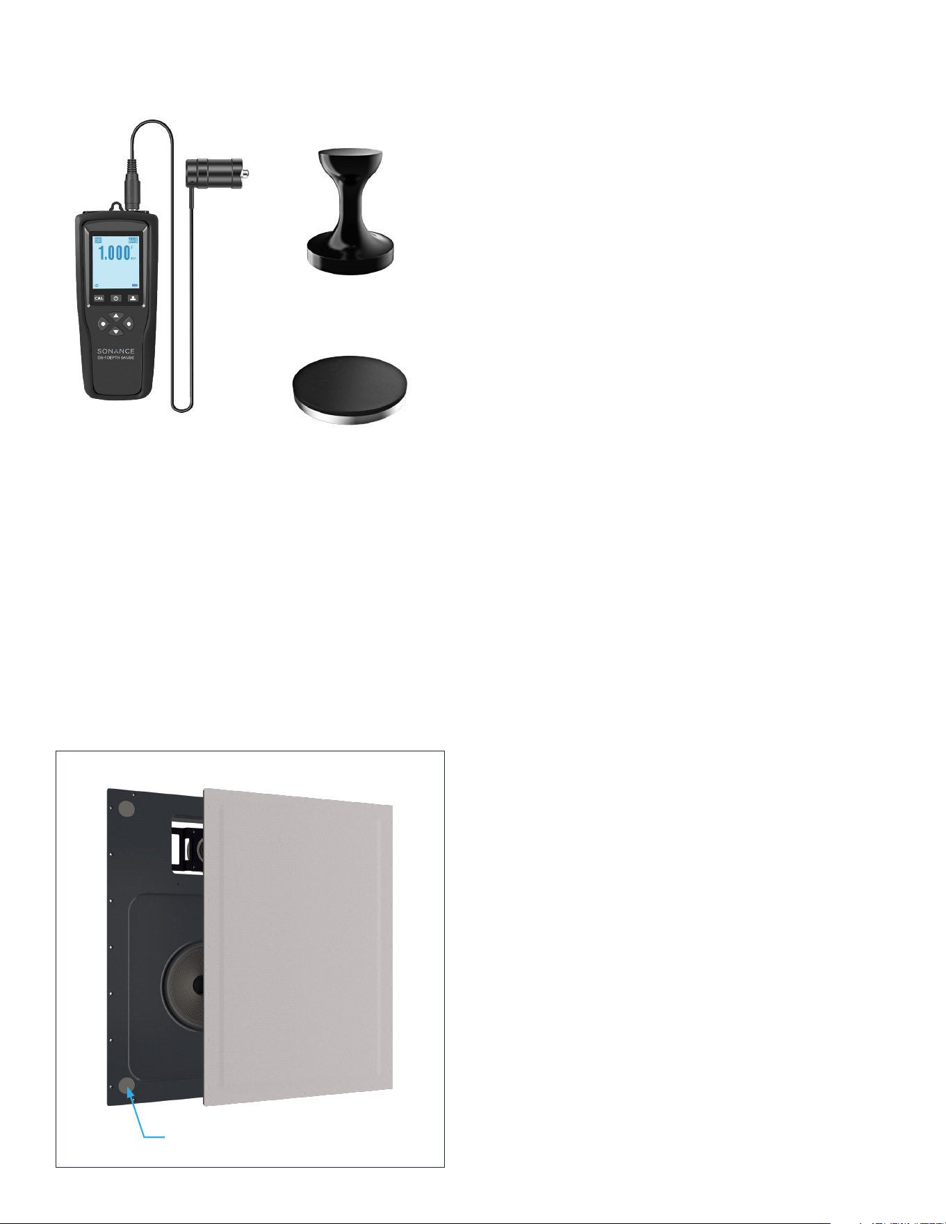
The Sonance DISC System provides a highly accurate
method for non-destructively quantifying the thickness
of a finish applied on top of a Sonance invisible speaker
diaphragm. The Sonance DG-1 handheld depth gauge
uses a magnetic sensor to measure the distance
between the top of the finished speaker and steel
discs embedded in all four corners behind the speaker
diaphragm of Sonance Motion Flex Invisible Speakers
(Figure 1).
The depth gauge has been pre-calibrated to account
for the invisible speaker’s total diaphragm thickness.
Therefore, the measurement you read on the gauge will
tell you the actual thickness of the finishing material
on the surface of the diaphragm, in mm—assuming you
have a smooth, level finish across the entire surface.
This system should be used after all drywall mud/
topping compound has been applied, feathered, leveled,
cured, and sanded—but before any priming, painting,
or final finishing steps are performed. This gives the
installer the opportunity to verify and potentially alter
the mud/finish thickness before it’s too late.
Staying within finish thickness requirements is critical
for an invisible speaker’s performance and longevity.
The ability to now quantify finish thickness allows the
installer to achieve consistent, predictable results that
unlock the full potential of fidelity and reliability that
Sonance invisible speakers are capable of.
BEFORE MEASURING
Measurements must be made after the Sonance
Invisible Series speaker or subwoofer has been fully
installed and the surface finished according to its
installation instructions but before priming, painting,
wallpaper, or other final finishes have been applied.
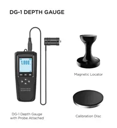
DG-1 DEPTH GAUGE
BOX CONTENTS
(1) Depth Gauge
(1) Wired Measurement Probe
(1) Magnetic Locator
(1) Calibration Disc
(1) Carrying Case
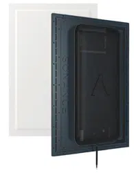
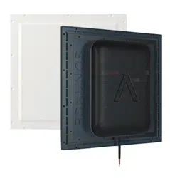
DG-1 Depth Gauge
with Probe Attached
Figure 1: Embedded Discs
Calibration Disc
Magnetic Locator
3
MEASURING FINISH THICKNESS
WITH THE DG-1
STEP 1
Prepare depth gauge by connecting the included
measurement probe and powering up the device. The
depth gauge comes pre-calibrated out of the box so
there is no need to calibrate before initial use.
NOTE: The probe must be attached BEFORE powering
up the device to ensure accurate measurements.
STEP 2
Identify rough speaker positions by using stud locations
and construction plans as a guide. Play music through
the speakers and feel for the woofer motion on the
wall or ceiling surface for further precision. Turn o the
music before measuring.
NOTE: The DG-1 depth gauge will not function while
music is playing through an invisible speaker.
STEP 3
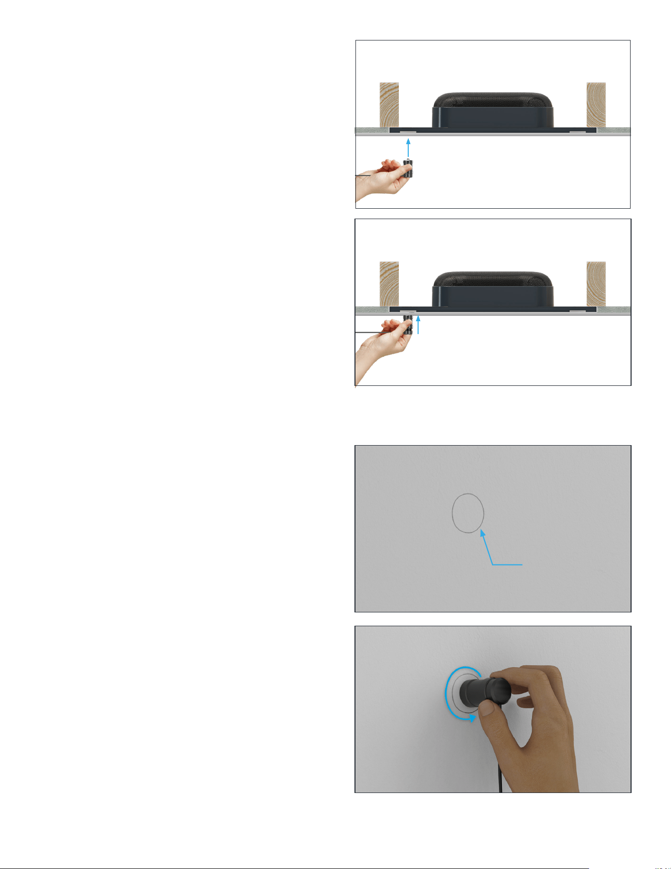
To find the embedded disc locations on each corner
of the speaker, start by gently placing the included
magnetic locator near the center of the woofer location
and then slide diagonally across the surface downward
and to the left toward the bottom left corner of the
speaker (Figure 2). You will feel the magnetic locator
snap firmly into place as it attracts to the edge of the
embedded steel disc. This is why stainless steel screws
are recommended in the mounting process for both the
speaker and surrounding drywall area to minimize false
detection. In order to center the locator closer to the
middle of the embedded disc, we recommend sliding
the locator down and to the left another 1/2” or
about 12mm. This typically results in a more accurate
pinpointing of where the embedded discs are and will
result in more accurate measurements.
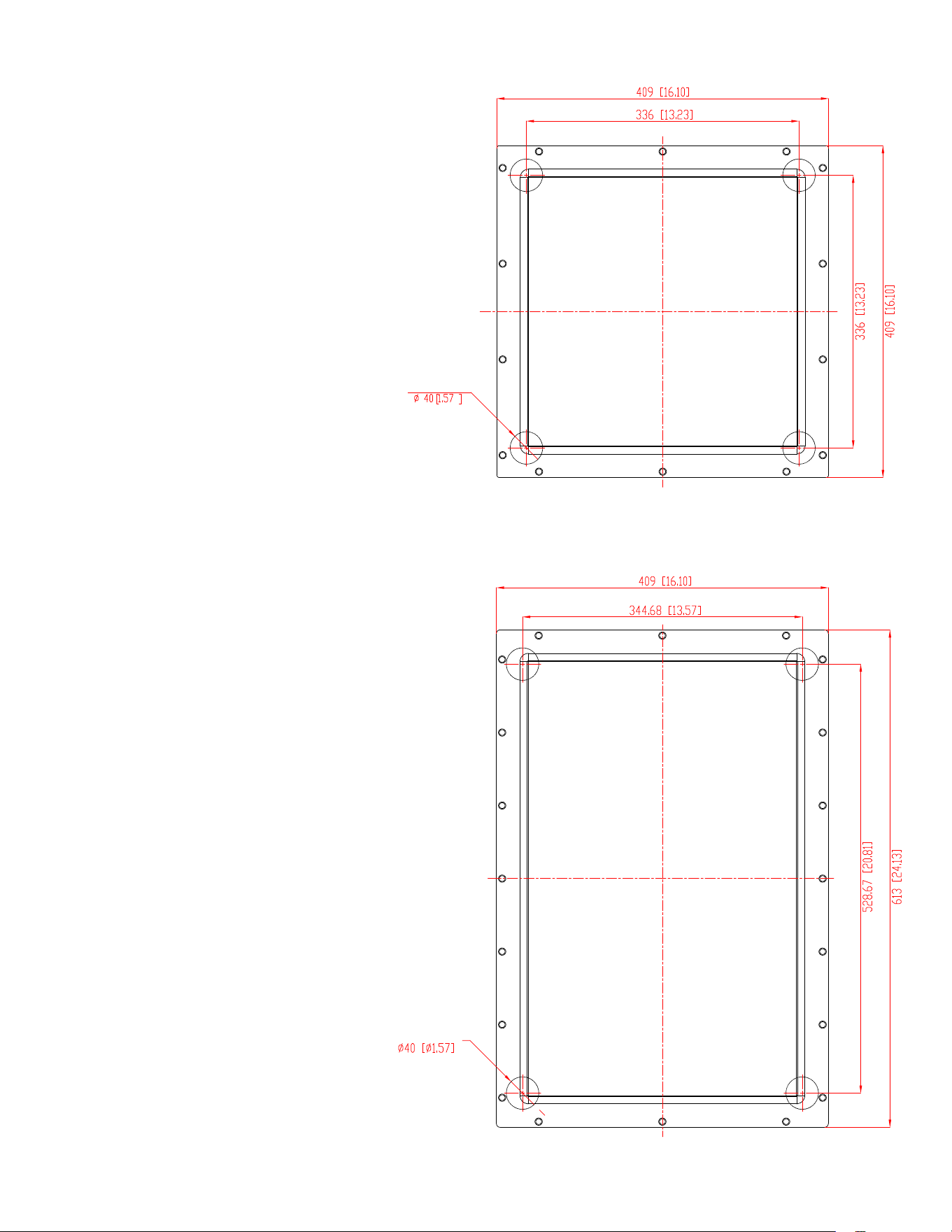
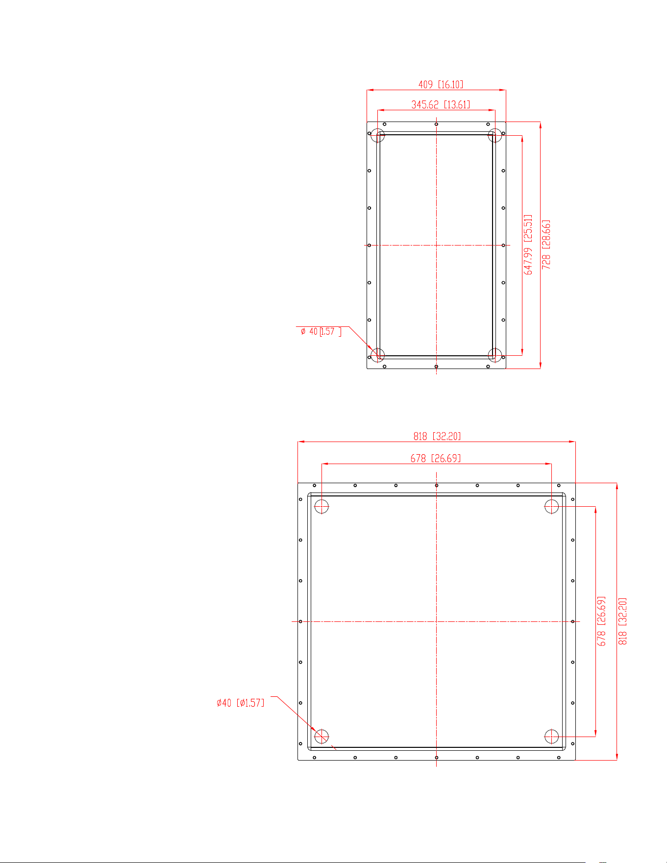
Dimensional drawings of the disc positions for Sonance
invisible speakers that use the DISC system can be
found on pages 6–7. Refer to www.sonance.com for the
most recent drawings.
STEP 4
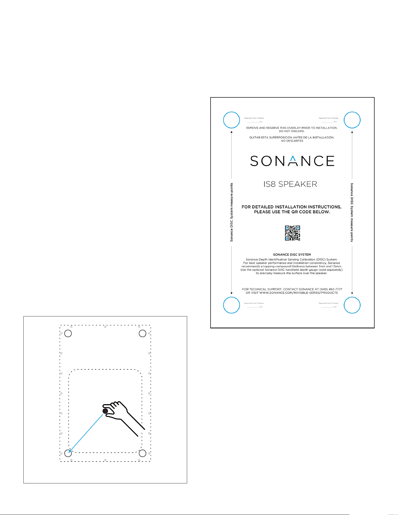
Mark around the perimeter of the magnetic locator
using a pencil. Repeat STEP 3 & 4 for all four corners.
Alternatively, use the invisible speaker’s included cutout
template (Figure 3) to quickly find the remaining three
disc locations. The cutout template makes this process
much more fool-proof.
NOTE: We highly recommend using the cutout
template (Figure 3) that is attached to the front of
every invisible speaker as a fast guide for locating
discs and recording measurements at each corner
location. The blue circles in each corner are punched
out for easy measurement. After finding the lower left
disc location, the cutout template can be laid directly
over the magnetic locator. The locator can then be
removed and all four locations can be measured.
Figure 3: Cutout Template for IS Speakers
Figure 2: Moving the magnetic locator from the center
of the woofer location to the lower left embedded disc.
4
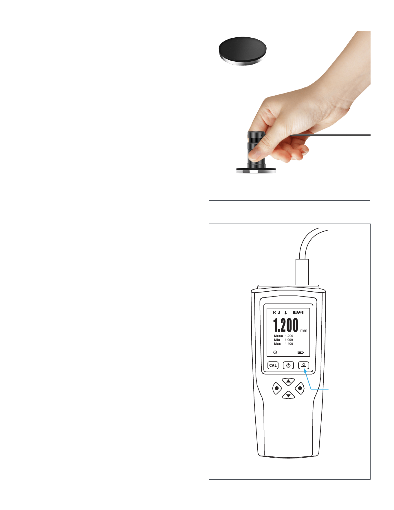
STEP 5
Place the measurement probe against the wall or ceiling
surface. Ensure the spring-loaded collar is touching the
surface evenly (Figure 4).
The best practice at this point is to slowly move the
probe in a circular motion around the area you marked
in STEP 4 (Figure 5).
Take note of the minimum depth registered on the
gauge as you move it around the marked disc area.
Pause for a couple seconds between each movement
to ensure the measurement has time to update on the
gauge’s display.
NOTE: As your measurement probe drifts from the
center of embedded disc, you will see the measured
thickness increase which could lead to inaccurate
measurements. Keep in mind that while it is possible
to get a reading higher than the actual finish thickness
if your alignment isn’t perfect, it is not possible to
measure less than the actual thickness. That is why
finding the minimum reading by circling or sweeping
the probe around the area of the embedded disc is
crucial.
The minimum measurement should be recorded for
this corner of the speaker. You can lightly mark the
measurement directly on the wall with a pencil, or
record the measurement onto the cutout template. We
recommend you repeat these steps on the remaining
three corners to ensure a consistent finish thickness.
It is likely that measurements at all four corners will
dier slightly. Variances of plus or minus 1/2mm are
perfectly acceptable as long as the overall finished
surface is smooth and level and as long as the actual
measurements don’t exceed 3mm.
If your measurement does exceed 3mm, sand down to
target thickness (we recommend between 1.0–1.5mm).
Ensure a smooth and even overall appearance with
the rest of the installation surface and then repeat the
measurement process to verify that the finish is below
the 3mm maximum and close to the target thickness.
STEP 6
Using a straight edge, check for surface flatness
across the speaker location horizontally, vertically, and
diagonally. We recommend a straight edge that will
span the full height, width, and diagonal of the installed
speaker.
If gaps or high spots of around 1mm (about 1/32”) or
more are found, or if total finish thickness exceeds
3mm, level the wall finish as needed by sanding down or
adding additional material.
Remember that an even, smooth surface finish will
ensure a totally hidden aesthetic for your invisible
speakers.
Figure 4: Placing the measurement probe
Figure 5: Slowly circling probe around marked disc location
Disc location
marked in pencil
5
DG-1 CARE AND HANDLING
The DG-1 is a precision tool, and though it is sturdy, it is
not immune to damage if mishandled.
Keep the gauge in its protective case when not in use.
Job sites tend to be extremely dusty. Always wipe away
any dust or debris after use.
Always hold the probe by the collar. Never let it dangle
or hold the probe by its cable.
“OVERFLOW” READING
Occasionally, the DG-1 may display the word “Overflow”.
This usually occurs when a measurement is registered
that is less than zero. The depth gauge is calibrated, or
“zeroed”, to account for the thickness of the speaker’s
diaphragm.
If the DG-1 repeatedly displays this message, you can
quickly recalibrate it using the instructions below.
CALIBRATION
Your DG-1 comes pre-calibrated; however, you may wish
to re-calibrate from time to time to ensure consistent
accuracy. To begin recalibration, connect the probe to
the depth gauge, power it on, and wait for it to fully
boot.
Prior to calibrating, it is recommended to clear out any
existing calibration data.
Press the Left Directional button to enter the “Root”
menu. Scroll down to the “Calibration” option and press
the Left Directional button to enter the Calibration
menu. Scroll down to “Clear All” and press the Left
Directional button once to select, and again to confirm
that you want to clear the current calibration data.
Press the Right Directional button twice to exit the
menu.
Fully depress the probe onto the black side of the
included calibration disc (Figure 6).
Press and hold the upper rightmost key (the zero key)
on the depth gauge (Figure 7). You will hear a single
beep as soon as you press the button. Hold until you
hear two more rapid beeps then release.
The two beeps indicate that the gauge has been zeroed
out, and the display should read 0.000 with the word
“ZERO” flashing at the bottom of the display.
Press the zero key once more to exit calibration mode.
The word “ZERO” should now disappear, and you are
ready to continue using the DG-1 depth gauge.
Figure 7
Figure 6: Depress probe against black
side of calibration disc
Zero Key
Calibration Disc
6
4 - Depth Discs
4 - Depth Discs
EMBEDDED DISC LOCATIONS
IS6
IS8/IS8T/IS10W
Dimensions displayed as: mm [in]
Dimensions displayed as: mm [in]
7
4 - Depth Discs
4 - Depth Discs
EMBEDDED DISC LOCATIONS
IS10
IS15W
Dimensions displayed as: mm [in]
Dimensions displayed as: mm [in]

8
LIMITED TWO (2) YEAR WARRANTY
Sonance warrants to the first end-user purchaser that this Sonance-brand product (“Product”), when purchased from
an authorized Sonance Dealer/Distributor, will be free from defective workmanship and materials for the period stated
below. Sonance will at its option and expense during the warranty period, either repair the defect or replace the Product
with a new or re-manufactured Product or a reasonable equivalent.
EXCLUSIONS
TO THE EXTENT PERMITTED BY LAW, THE WARRANTY SET FORTH ABOVE IS IN LIEU OF, AND EXCLUSIVE OF,
ALL OTHER WARRANTIES, EXPRESS OR IMPLIED, AND IS THE SOLE AND EXCLUSIVE WARRANTY PROVIDED
BY SONANCE. ALL OTHER EXPRESS AND IMPLIED WARRANTIES, INCLUDING THE IMPLIED WARRANTIES OF
MERCHANTABILITY, IMPLIED WARRANTY OF FITNESS FOR USE, AND IMPLIED WARRANTY OF FITNESS FOR A
PARTICULAR PURPOSE ARE SPECIFICALLY EXCLUDED.
No one is authorized to make or modify any warranties on behalf of Sonance. The warranty stated above is the sole and
exclusive remedy, and Sonance’s performance shall constitute full and final satisfaction of all obligations, liabilities, and
claims with respect to the Product.
IN ANY EVENT, SONANCE SHALL NOT BE LIABLE FOR CONSEQUENTIAL, INCIDENTAL, ECONOMIC, PROPERTY,
BODILY INJURY, OR PERSONAL INJURY DAMAGES ARISING FROM THE PRODUCT, ANY BREACH OF THIS WARRANTY,
OR OTHERWISE.
This warranty statement gives you specific legal rights, and you may have other rights which vary from state to state.
Some states do not allow the exclusion of implied warranties or limitations of remedies, so the above exclusions and
limitations may not apply. If your state does not allow disclaimer of implied warranties, the duration of such implied
warranties is limited to period of Sonance’s express warranty. Your Product Model and Description: DG-1 Depth Gauge.
Warranty Period for this Product: Two (2) years from the date on the original sales receipt or invoice or other satisfactory
proof of purchase. Additional Limitations and Exclusions from Warranty Coverage: The warranty described above is
nontransferable, applies only to the initial installation of the Product, does not include installation of any repaired or
replaced Product, does not include damage to allied or associated equipment which may result for any reason from use
with this Product, and does not include labor or parts caused by accident, disaster, negligence, improper installation,
misuse (e.g. overdriving the amplifier or speaker, excessive heat, cold or humidity, mishandling, etc.), or from service
or repair which has not been authorized by Sonance. Obtaining Authorized Service: To qualify for the warranty, you
must contact your authorized Sonance Dealer/Installer or call Sonance Customer Service at (949) 492-7777 within the
warranty period, must obtain a return merchandise number (RMA), and must deliver the Product to Sonance shipping
prepaid during the warranty period, together with the original sales receipt, or invoice or other satisfactory proof of
purchase.
©2020 Sonance. All rights reserved. Sonance is a registered trademarks of Dana Innovations. Due to continuous product improvement,
all features and specifications are subject to change without notice. For the latest Sonance product specification information visit our
website: www.sonance.com
SONANCE • 991 Calle Amanecer • San Clemente, CA 92673 USA
PHONE: (949) 492-7777 • FAX: (949) 361-5151 • Technical Support: (949) 492-7777 • www.sonance.com
12.09.2020