
◆Technical Features
1、Powerful, stable and reliable car-grade processor,CPU:MT8768WA;
2
、Conforms to IP67 technical specification;
3、Equipped with super 8-core processor, main frequency 2GHz, onboard
2GB mem
ory, 16GB storage;
4、CANBus、Serial、LTE;USB
5、Wide voltage input, 6-36VDC;
6、Dual SIM;
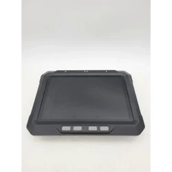
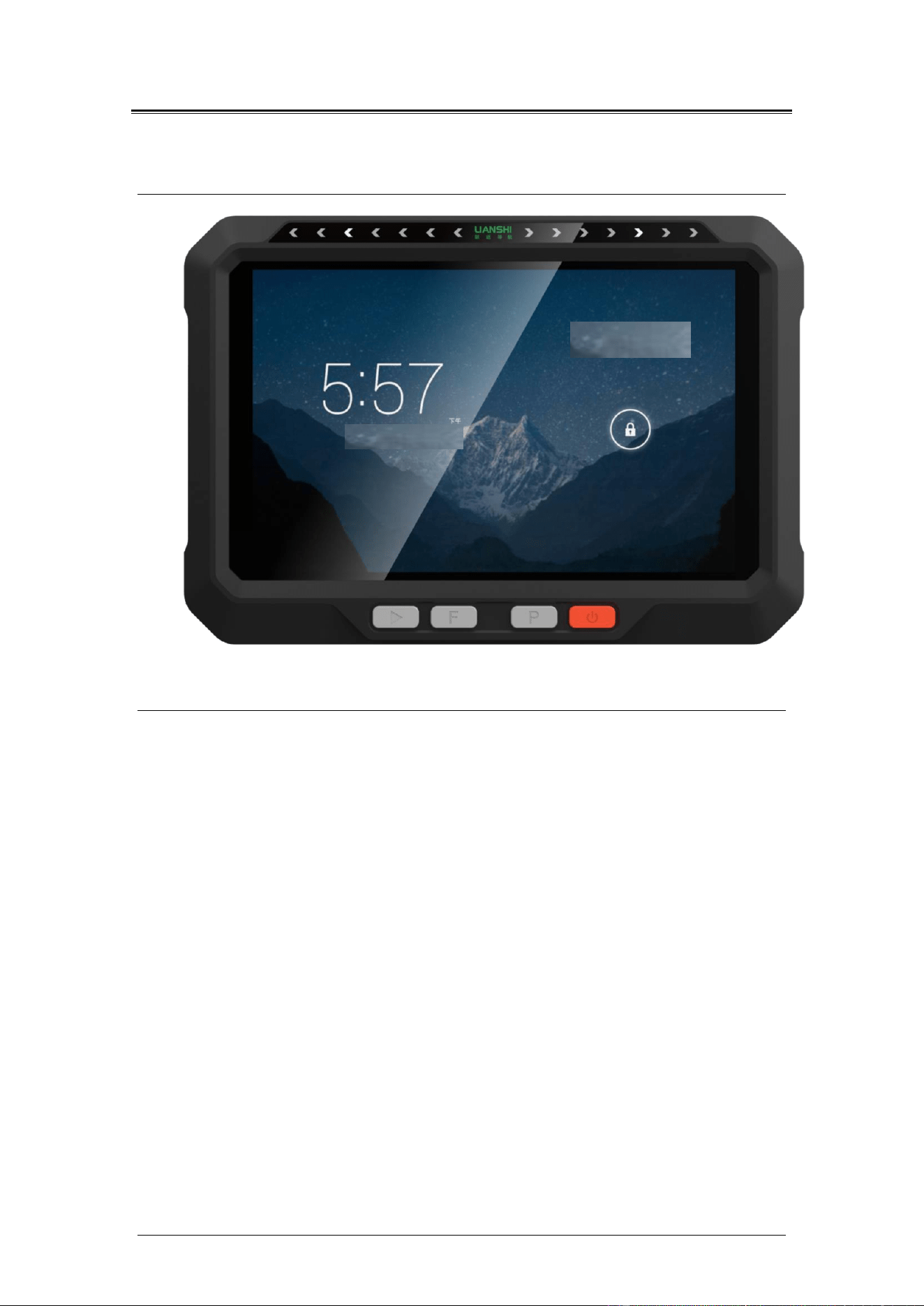
7、10.1-inch capacitive touch screen, support 10-finger touch,
resolution 1280*800P, brightness 750nits;
8、The system uses Android 12.0;
9、Optical target design, status information at a glance;

◆Technical Parameters
Electrical parameters
●power consumption:≤12.0W
●supply voltage:DC 6~36V
Physical properties
●Operating temperature:-20℃~+60℃
●Storage temperature:-40℃~+70℃
●Resolution:1280*800P
●screen size:10.1 inch
●weight: 1.36Kg
●degree of protection: IP67
Communication Interface:
●RS232*2
●RS485*1
●CAN*2
●USB2.0*1
●DI*2,DO*2
●12VDCOUT*1
●Analog camera input *4
GNSS parameters
1. BDS B1I/B2I/B3I 、GPS L1C/A/L2P (Y)/L2C/L5、Galileo E1/E5a/E5b 、GLONASS
G1/G2 、QZSS L1/L2/L5
2. Channel:1408 channels,base on NebulasII
3. RTK(RMS):Horizontal:0.8cm+1ppm 、Vertical:1.5cm+1ppm
4. Orientation accuracy (RMS):0.1 degrees/1m baseline
5. Speed accuracy (RMS):0.03m/s
6. Differential data:RTCM 3.X
7. Data format :NMEA-0183
8. Initialization time:<5s(typical value)
9. Initialization Reliability:>99.9%
10. Time to first fix:<25s
11. data update rate:20Hz
12. Roll accuracy:0.2 degrees/1m baseline
◆Interface definition
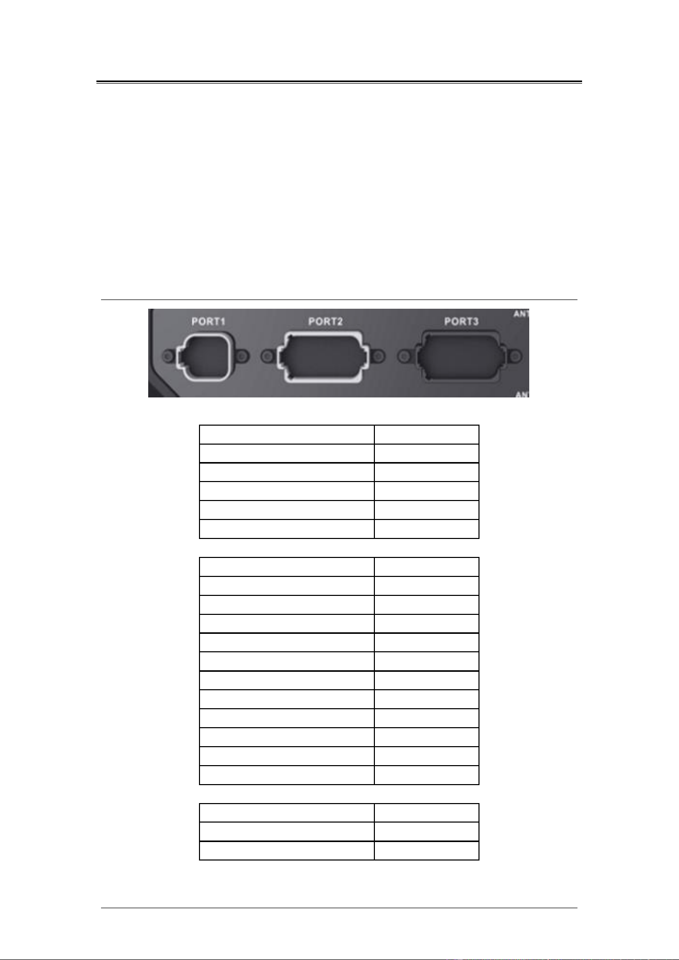
PORT1
1
CAMERA12V
2
GND
3
CAMERAIN3
4
CAMERAIN2
5
CAMERAIN1
6
CAMERAIN4
PORT2
1
RS232A-TX
2
RS232A-RX
3
B+
4
ACC
5
B-
6
GND
7
RS232B-RX
8
CAN1-L
9
CAN1-H
10
INPUT-GPIO
11
RS232B-TX
12
GND
PORT3
1
RS485A
2
RS485B
3
4
DC12V-OUT
5
CAN2-L
6
CAN2-H
7
N/RJ45TX+
8
N/RJ45TX-
9
12VOUT1/RJ45RX+
10
12VOUT2/RJ45RX-
11
GPIOIN2
12
GND
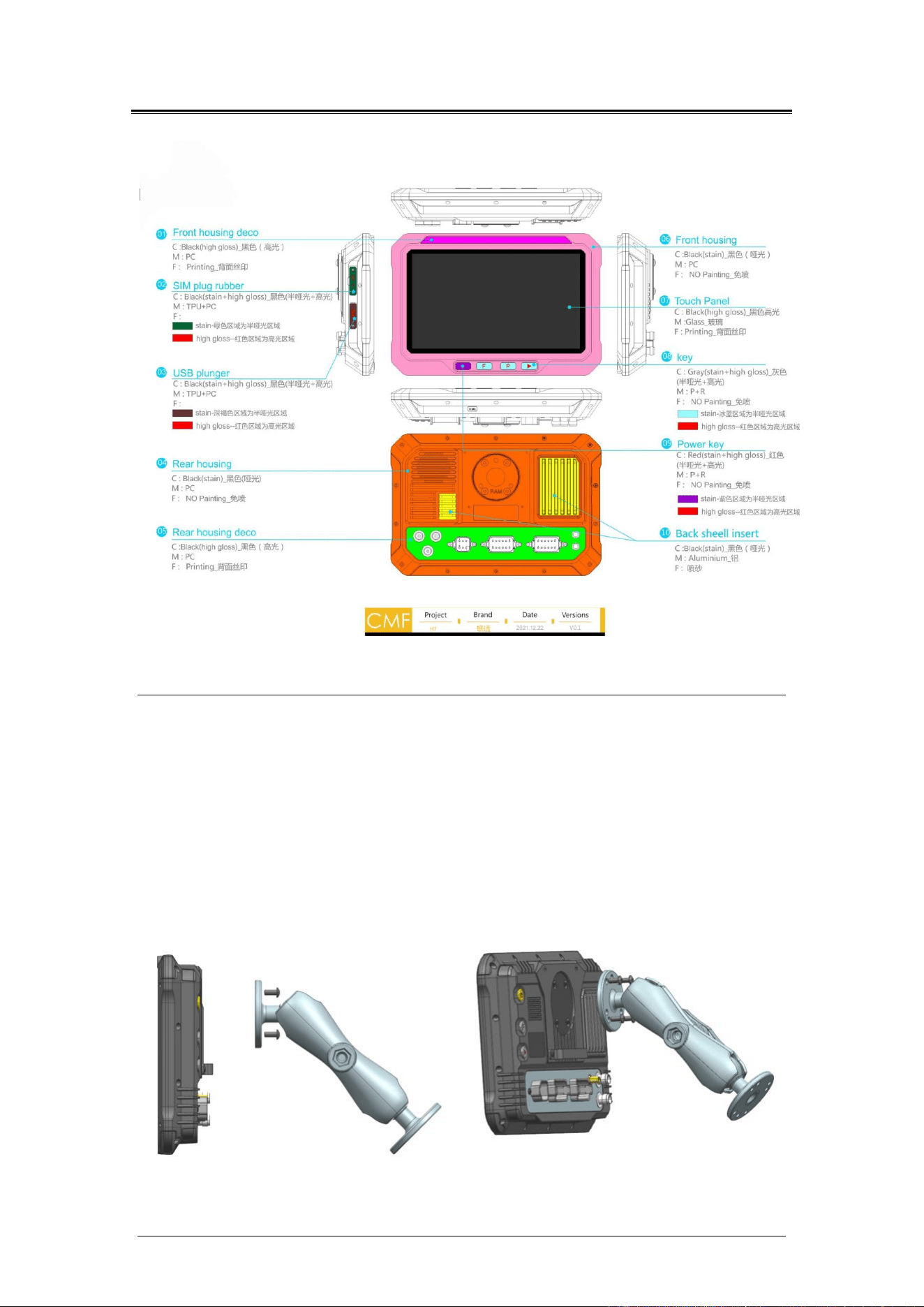
◆Appearance design
◆equipment installation
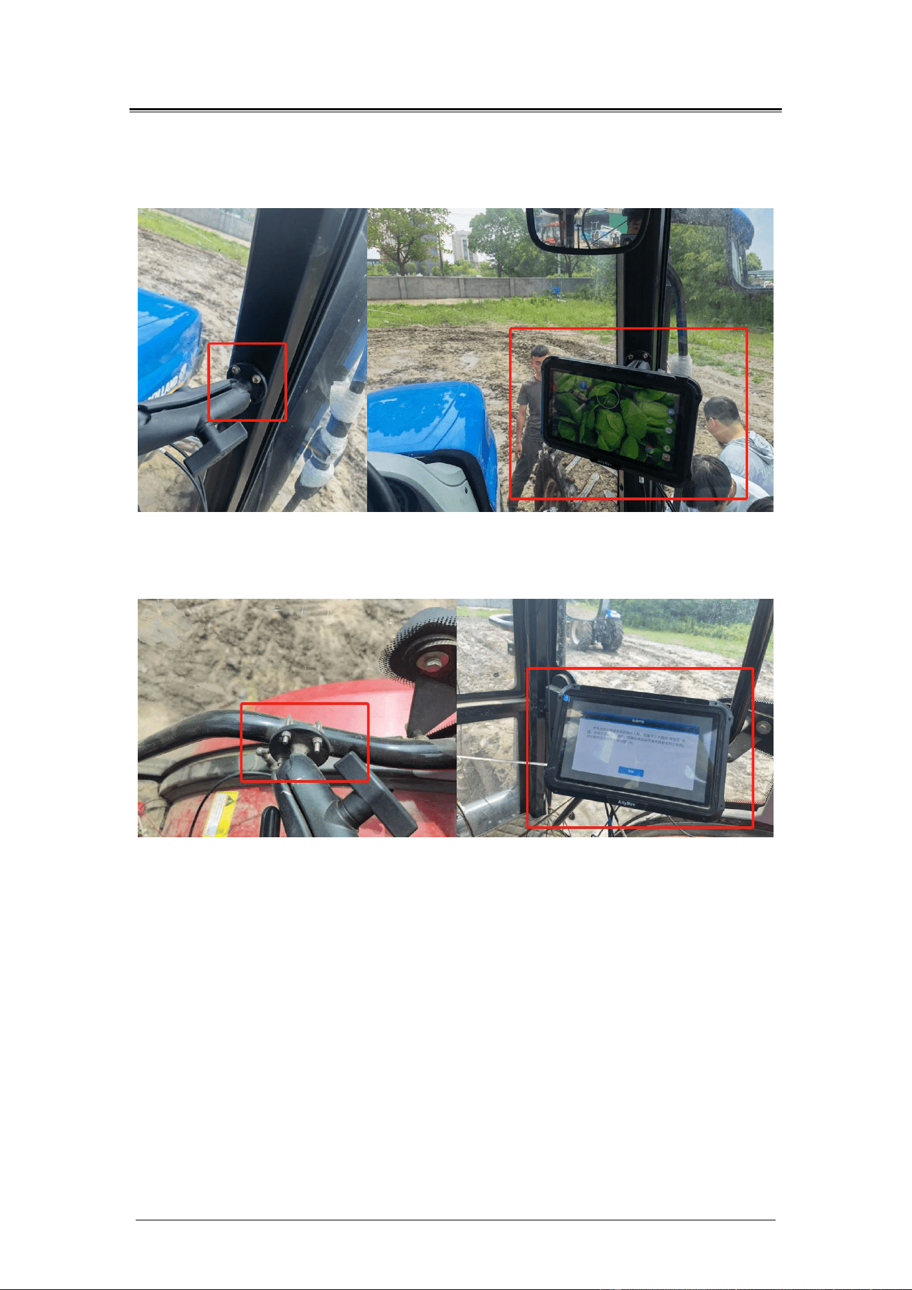
The plate is mounted through the RAM bracket in the cab for
customer operation. RAM supports are generally fixed in two ways:
self-tapping screws and U-shaped cards.
Plate assembly schematic diagram:
3-1
Effect of self-tapping screws:
3-2
U-type card installation effect diagram
3-3
Note: Use U-type card as the first choice. If you use self-tapping to
install the plate, it must be installed with the consent of the
customer.

FCC Statement
Any Changes or modifications not expressly approved by the party responsible for compliance could void
the user’s authority to operate the equipment.
This device complies with part 15 of the FCC Rules. Operation is subject to the following two conditions:
(1) This device may not cause harmful interference, and
(2) This device must accept any interference received, including interference that may cause
undesired operation.
FCC Radiation Exposure Statement:
This equipment complies with FCC radiation exposure limits set forth for an uncontrolled
environment .This equipment should be installed and operated with minimum distance 30cm between the
radiator& your body.
RF warning for Portable device:
The device has been evaluated to meet general RF exposure requirment. The device can be used in
portable exposure condition without restriction.
Note : This equipment has been tested and found to comply with the limits for a Class B digital device,
pursuant to part 15 of the FCC Rules. These limits are designed to provide reasonable protection against
harmful interference in a residential installation. This equipment generates,uses and can radiate radio
frequency energy and, if not installed and used in accordance with the instructions, may cause harmful
interference to radio communications. However, there is no guarantee that interference will not occur in a
particular installation. If this equipment does cause harmful interference to radio or television reception,
which can be determined by turning the equipment off and on, the user is encouraged to try to correct the
interference by one or more of the following measures:
—Reorient or relocate the receiving antenna.
—Increase the separation between the equipment and receiver.
—Connect the equipment into an outlet on a circuit different from that to which the receiver is connected.
—Consult the dealer or an experienced radio/TV technician for help.