
10-9-2025
10-9-2025
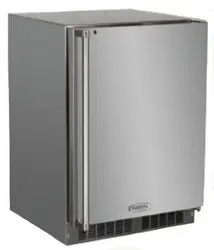
MRDR224-SS71A
Model: MRDR224-IS71A
Model: MRDR224-IS71A

Installing YourAppliance & Install Door Handle
Contents
Welcome ......................................................................... 3
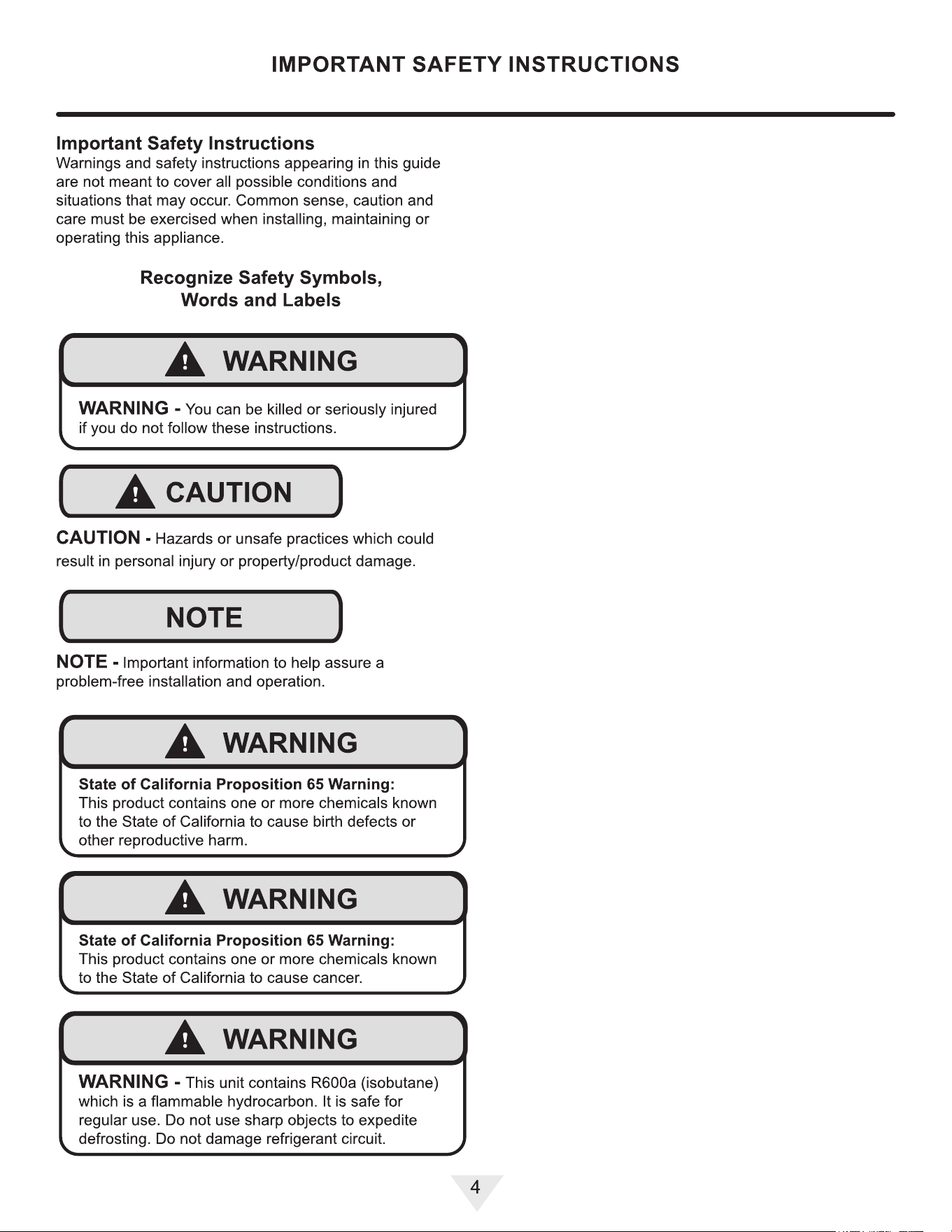
Important Safety Instructions .......................................... 4
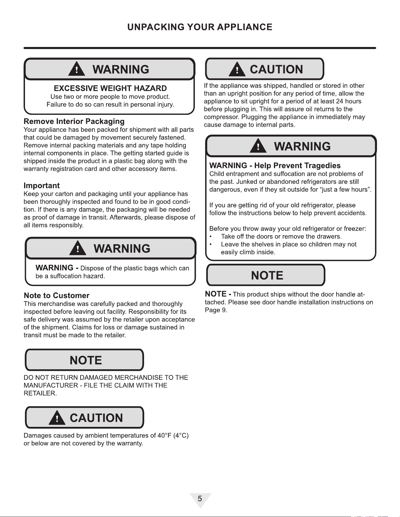
Unpackig Your Appliance ................................................ 5
Electrical ......................................................................... 6
Cutout and Product Dimensions ..................................... 7
Installing Your Appliance ................................................. 9
Integrated Panel Dimensions and Installation ................ 10
Using Your Electronic Control ......................................... 11
Care and Cleaning .......................................................... 12
Stainless Steel Maintenance ........................................... 13
Energy Saving Tips ......................................................... 14
Extended Non-Use .......................................................... 15
Obtaining Service ............................................................ 16
Troubleshooting ............................................................... 17
Wire Diagram ................................................................... 19
Product Liability ............................................................... 20
Warranty Claims .............................................................. 21
Ordering Replacement Parts ........................................... 22
R600a Specications ....................................................... 23
Warranty .......................................................................... 27
2
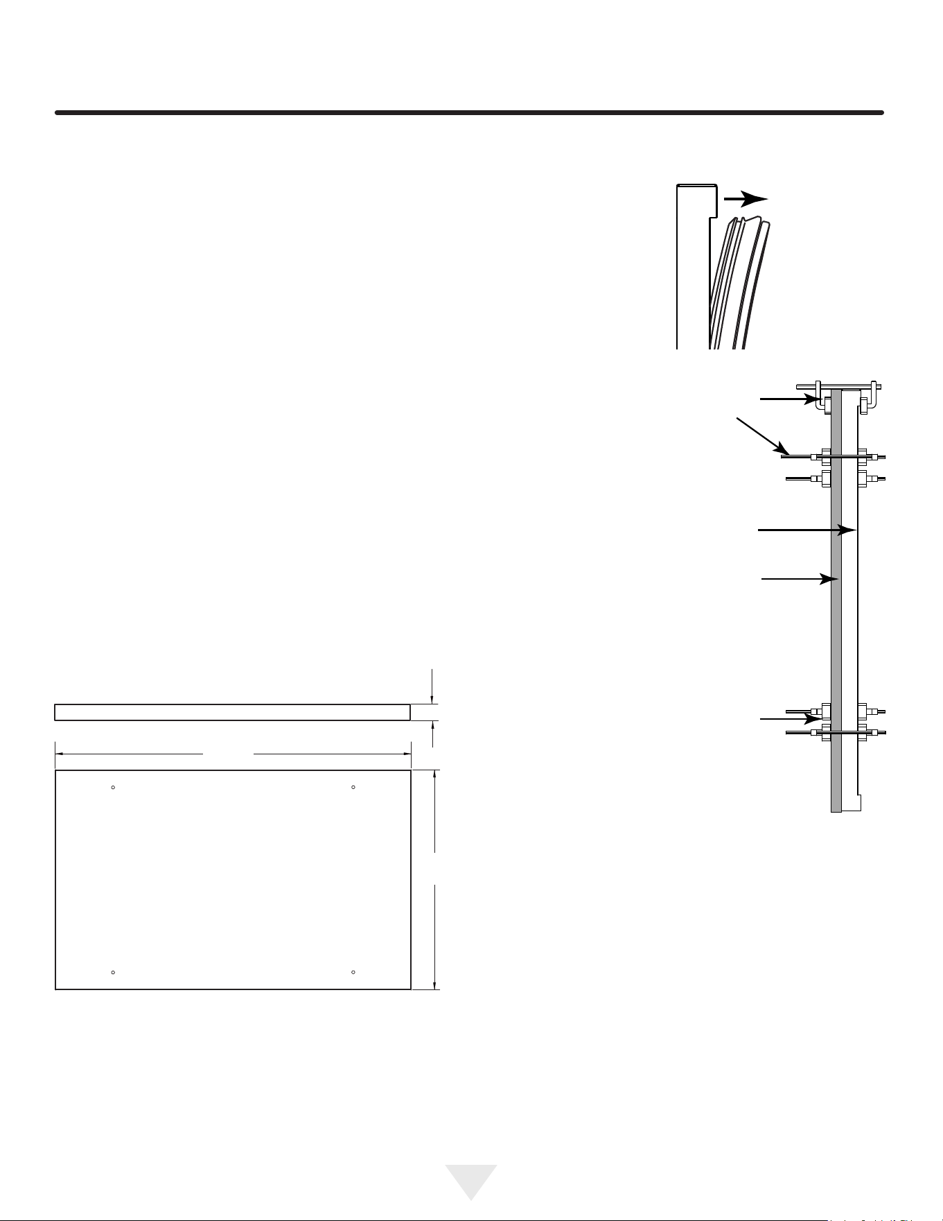
CUTOUT AND PRODUCT DIMENSIONS
ROUG
H
-IN OPENING DIMENSIONS
CAB
INET DIMENSIONS
"
A
"
"
B
"
"
C
"
"
D
"
23 %"
|
33 %" to 34
%"
|
24
'
’
|
23
1
"
(60.3 cm) I (85.4 cm to 89.5 cm) I
(61 cm) I (60 cm)
"
E
"
"F"
"
G
"
"
H
"
33%"to34%
'
| 22
9
/
16
" | 24%"
(85 cm to 88 cm)
34
3
/
8
"
87.3 cm)
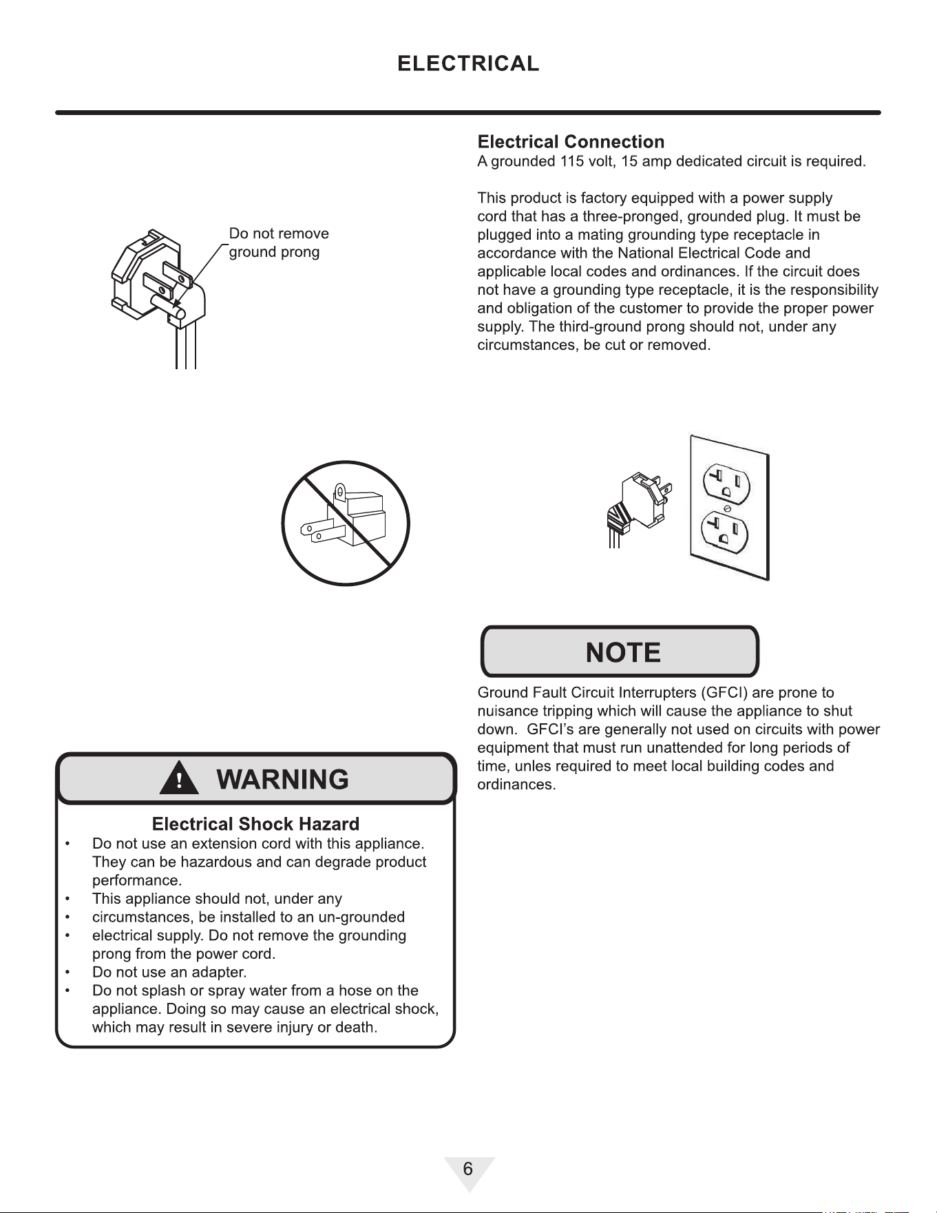
If
necessary, to gain clearance inside the rough-in
opening,
a hole can be cut through the adjacent
cabinet
and the power cord routed through this hole to
a
power outlet. Another wa
y to increase the available
opening
depth is to recess the power outlet into the
rear
wall to gain the thickness of the power cord plug.
Not
all recessed outlet boxes will work for this
application
as the
y are too narrow, but a recessed
outlet
box equivalent to Arlington #DVFR1 W us
recommended
for this application.
7
(57.3 cm)
(61.3 cm)
CUTOUT AND PRODUCT DIMENSIONS
ROUG
H
-IN OPENING DIMENSIONS
CAB
INET DIMENSIONS
"
A
"
"
B
"
"
C
"
"
D
"
23 %"
|
33 %" to 34
%"
| 24
'
’
|
23
1
"
(60.3 cm) I (85.4 cm to 89.5 cm) I
(61 cm) I (60 cm)
"
E
"
"F"
"
G
"
"
H
"
33%"to34%
'
| 22
9
/
16
" | 24%"
(85 cm to 88 cm)
34
3
/
8
"
87.3 cm)
If necessary, to gain clearance inside the rough-in
opening, a hole can be cut through the adjacent
cabinet and the power cord routed through this hole to
a power outlet. Another way to increase the available
opening depth is to recess the power outlet into the
rear wall to gain the thickness of the power cord plug.
Not all recessed outlet boxes will work for this
application as the
y are too narrow, but a recessed
outlet box e
quivalent to Arlington #DVFR1 W us
recommended for this application.
7
(57.3 cm)
(61.3 cm)
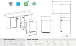
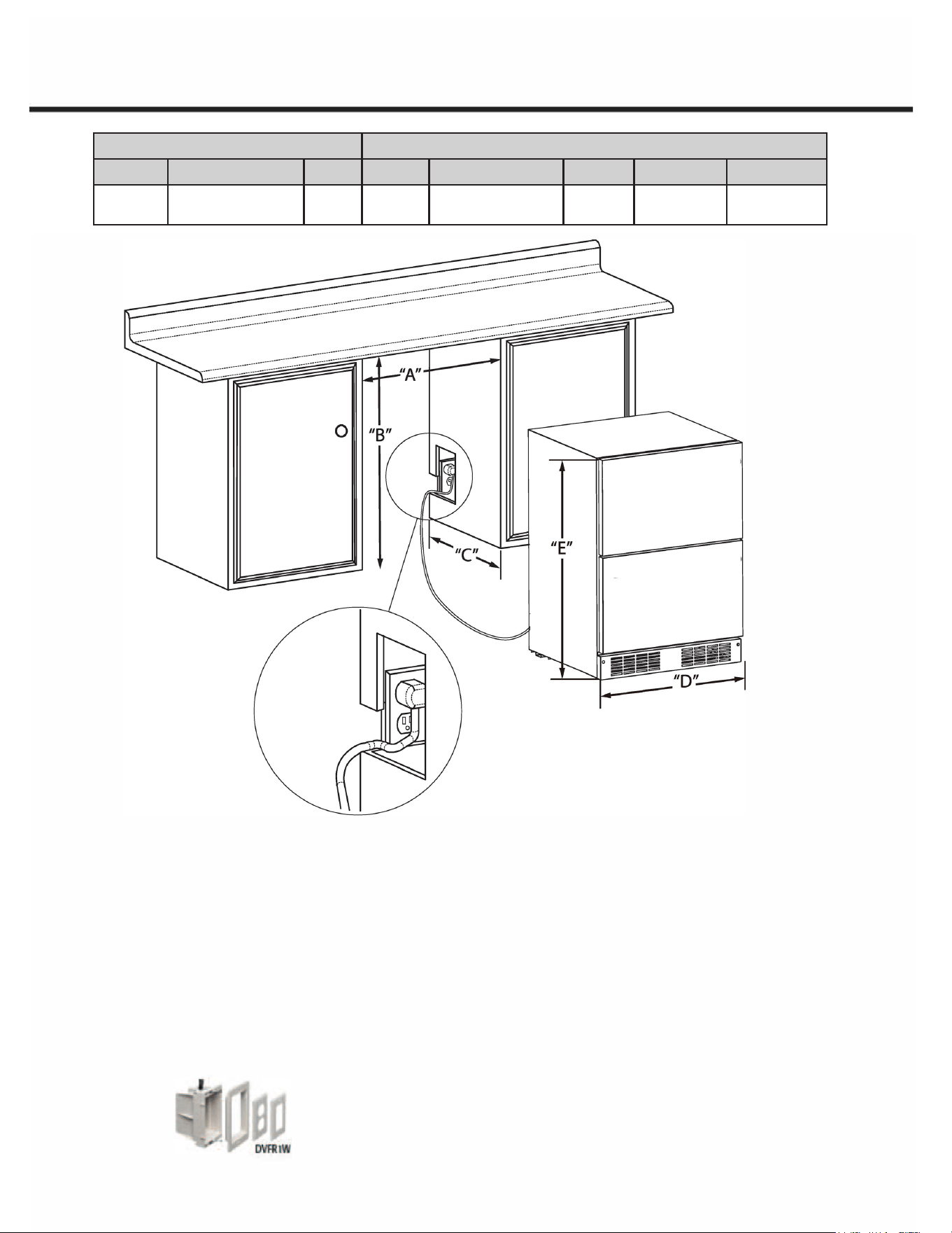
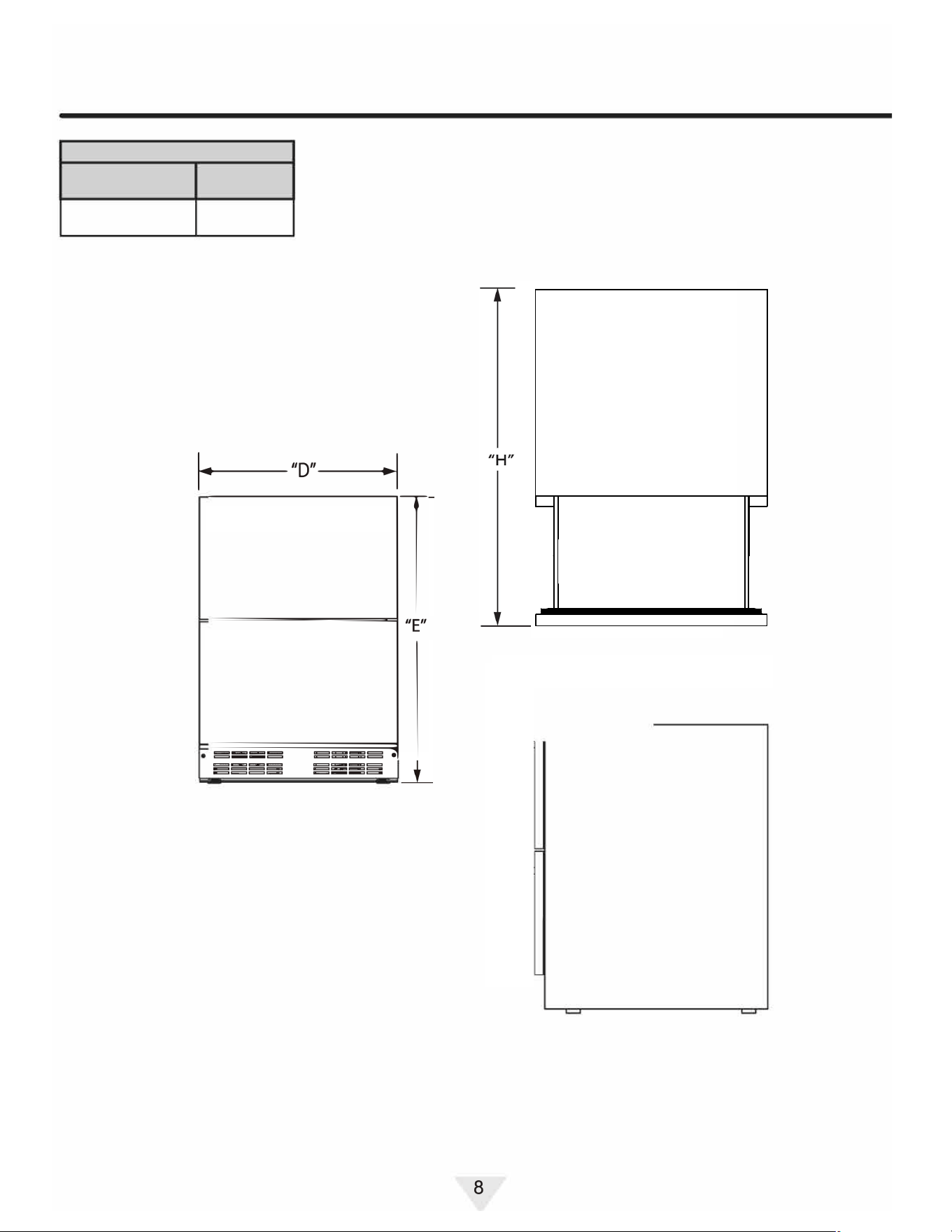
ROUGH-IN OPENING DIMENSIONS CABINET DIMENSIONS
“A” “B” “C” “D” “E” “F” “G” “H”
23 ³⁄4”
(60.3)
33 ⁵⁄8 to 34 ⁵⁄8”
(85.4 cm to 89.5 cm)
24”
(61 cm
23 ¹⁄2”
(60 cm)
33 ¹⁄2” to 34 ¹⁄2”
(85 cm to 88 cm)
22 ⁹⁄16”
(57.3 cm)
24 ¹⁄8”
(61.3) cm
34 ³⁄8”
(87.3 cm)
CUTOUT AND PRODUCT DIMENSIONS
ROUG
H
-IN OPENING DIMENSIONS
CAB
INET DIMENSIONS
"
A
"
"
B
"
"
C
"
"
D
"
23 %"
|
33 %" to 34
%"
| 24
'
’
|
23
1
"
(60.3 cm) I (85.4 cm to 89.5 cm) I
(61 cm) I (60 cm)
"
E
"
"F"
"
G
"
"
H
"
33%"to34%
'
| 22
9
/
16
" | 24%"
(85 cm to 88 cm)
34
3
/
8
"
87.3 cm)
If necessary, to gain clearance inside the rough-in
opening, a hole can be cut through the adjacent
cabinet and the power cord routed through this hole to
a power outlet. Another way to increase the available
opening depth is to recess the power outlet into the
rear wall to gain the thickness of the power cord plug.
Not all recessed outlet boxes will work for this
application as they are too narrow, but a recessed
outlet box e
quivalent to Arlington #DVFR1 W us
recommended for this application.
7
(57.3 cm)
(61.3 cm)
CUTOUT AND PRODUCT DIMENSIONS
ROUG
H
-IN OPENING DIMENSIONS
CAB
INET DIMENSIONS
"
A
"
"
B
"
"
C
"
"
D
"
23 %"
|
33 %" to 34
%"
| 24
'
’
|
23
1
"
(60.3 cm) I (85.4 cm to 89.5 cm) I
(61 cm) I (60 cm)
"
E
"
"F"
"
G
"
"
H
"
33%"to34%
'
| 22
9
/
16
" | 24%"
(85 cm to 88 cm)
34
3
/
8
"
87.3 cm)
If necessary, to gain clearance inside the rough-in
opening, a hole can be cut through the adjacent
cabinet and the power cord routed through this hole to
a power outlet. Another way to increase the available
opening depth is to recess the power outlet into the
rear wall to gain the thickness of the power cord plug.
Not all recessed outlet boxes will work for this
application as the
y are too narrow, but a recessed
outlet box e
quivalent to Arlington #DVFR1 W us
recommended for this application.
7
(57.3 cm)
(61.3 cm)
ROUGH-IN OPENING DIMENSIONS CABINET DIMENSIONS
“A” “B” “C” “D” “E” “F” “G” “H”
23 ³⁄4”
(60.3)
33 ⁵⁄8 to 34 ⁵⁄8”
(85.4 cm to 89.5 cm)
24”
(61 cm
23 ¹⁄2”
(60 cm)
33 ¹⁄2” to 34 ¹⁄2”
(85 cm to 88 cm)
22 ⁹⁄16”
(57.3 cm)
24 ¹⁄8”
(61.3) cm
34 ³⁄8”
(87.3 cm)
ROUGH-IN OPENING DIMENSIONS CABINET DIMENSIONS
“A” “B” “C” “D” “E” “F” “G” “H”
23 ³⁄4”
(60.3)
33 ⁵⁄8 to 34 ⁵⁄8”
(85.4 cm to 89.5 cm)
24”
(61 cm
23 ¹⁄2”
(60 cm)
33 ¹⁄2” to 34 ¹⁄2”
(85 cm to 88 cm)
22 ⁹⁄16”
(57.3 cm)
-
34 ³⁄8”
(87.3 cm)
CUTOUT AND PRODUCT DIMENSIONS
PRODUCT DATA
ELECTRICAL
PRODUCT
REQUITEMENTS #
WEIGHT
115V/60Hz/15A
95.9lbs
(4
3.5
k
g)
〔
二
一
广
二
n
Minimum rough-in opening is required to be larger than the
adjusted height of the cabinet.
A grounded 15-am
p dedication circuit is required. Follow all
local building codes when installing electrical and
a
ppliance.
8
Install the Door Handle
Install first Stud
·Remove protective coating before installation of door
handle.
·Locate the pre-drilled hole on the outside of the drawer.
·Take the provided stud and hand-tighten into the hole
until secure.
· Attach Handle
·Align one end of the handle over the mounted studs.
·Use the provided Allen wrench to tighten the set
screw underneath the handle.
·Do not overtighten — just enough to hold the handle
snugly in place.
· Repeat for second stud
·Locate the second hole on the drawer.
·Hand-tighten the remaining stud into the hole.
·Position the other end of the handle on the stud and
tighten the lower set screw using the Allen wrench.
· Repeat for second drawer
· Final Check
·Confirm that the handle is secure, level, and does
not wobble.
INTEGRATED PANEL INSTALLATION
Full Overlay Panel Installation Instructions
Determine Wood Screw Requirements
1. A #10 pan head wood screw should be used to proper-
ly secure the overlay panel. A quantity of 8 screws will
be needed - 4 for each panel.
2. Use only pan head screws.
3. If your overlay panel is thinner than
5
⁄8" (16 mm) you will
need to purchase shorter screws. The longer screws
will break through the front of the panel.
15
Integrated Panel Dimensions
• Panel thickness cannot exceed 3/4” (20 mm).
• If your overlay panel is thinner than 5/8” (16 mm), you
will need to purchase shorter screws. The longer
screws will break through the front of the panel.
23 3⁄8”
(593 mm)
5/8” to 3/4”
(16 mm to 20 mm)
14 7⁄16”
(366 mm)
Attach Overlay Panels to Drawers
1. Remove drawers from unit.
2. Remove gaskets
from drawers. Start
at one corner and
pull gasket from its
channel.
3. Set gasket aside,
laying it on a at
surface.
4. Set the overlay panel on
drawer front face and align
edges. The custom overlay
panel should be ush with
the top of the drawer and
centered on the width of
the drawer.
5. Clamp panel in position,
aligned with the top of the
drawer face.
6. Mark pilot hole locations,
using the 4 pilot holes in
the gasket channel.
7. Drill 4 pilot holes into the
overlay panel, ensuring not
to drill all the way through
the panel.
8. Use 4 wood screws to
secure the panel to the
drawer face.
9. Reinstall gasket.
10. Reinstall drawer.
Wood
Panel
Door/Drawer
Bar
Clamp
Bar
Clamp
10
34 61
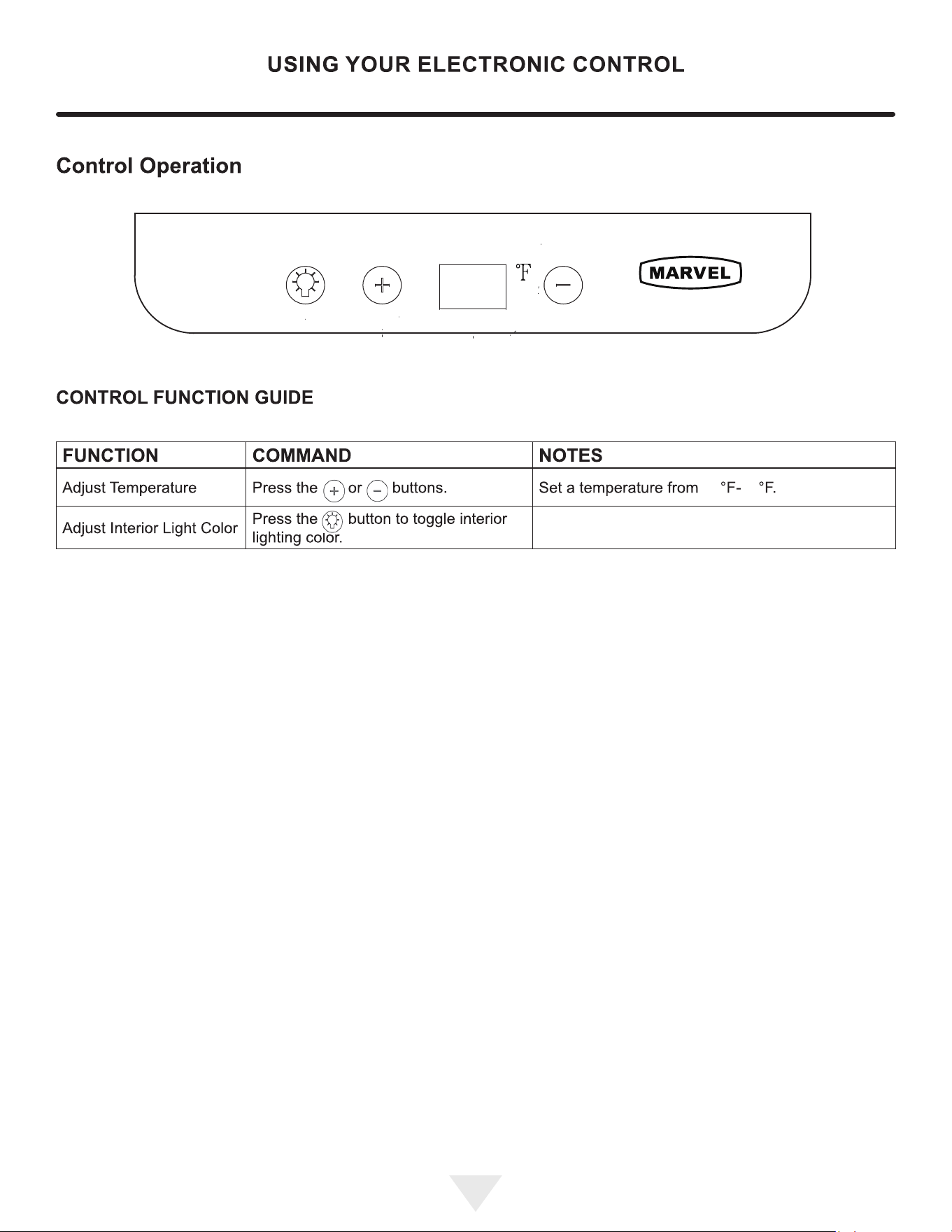
Toggle between bright white, warm white, coolwhite,
light blue, blue, and teal interiorLED lighting.
11
11

CARE AND CLEANING
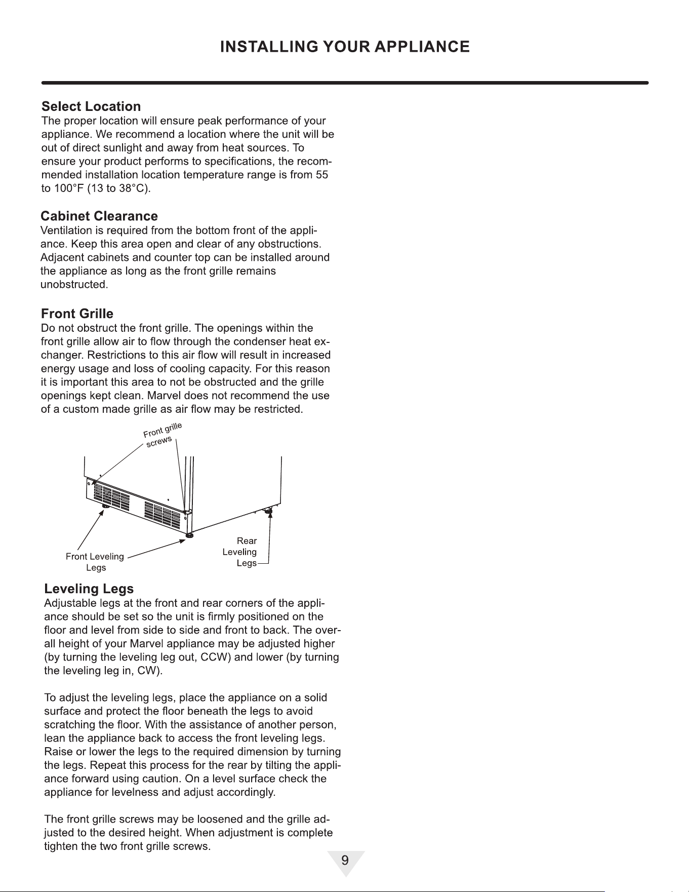
Front G『ille
Be sure that nothing obstructs the required air flow open
ings in front of the cabinet. At least once or twice a year,
brush or vacuum lint and dirt from the front grille area.
(
A CAUTION
`
`
,
'
,
'
SHOCK HARD: Disconnect electrical power from the
appliance before cleaning with soap and water.
Cabinet
The painted cabinet can be washed with either a mild soap
and water and thoroughly rinsed with clear water. NEVER
use abrasive scouring cleaners.
lnterio『
Wash interior compartment with mild soap and water. Do
NOT use an abrasive cleaner, solvent, polish cleaner or
undiluted detergent.
Care of Appliance
1.
Avoid leaning on the door, you may bend the door hing
es or tip the appliance.
2.
Exercise caution when sweeping, vacuuming or mop
ping near the front of the appliance. Damage to the
grille can occur.
3.
Periodically clean the interior of the appliance as need
ed.
4.
Periodically check and/or clean the front grille as need
ed.
In the Event of a Power Failure
If a power failure occurs, try to correct it as soon as possi
ble. Minimize the number of door openings while the power
is o so as not to adversely affect the appliance's tempera
ture.
Light assembly replacement
All models use LED lamps to illuminate the interior of the
appliance. This component is very reliable, but should one
fail, contact a qualified service technician for replacement
of the LED.
11
12
12

SINLESS STEEL MAINTENANCE
Background
Stainless steel products should never be installed, or stored
Stainless steel does not stain, corrode, or rust as easily as
in close proximity to chlorine chemicals.
ordinary steel, but it is not stain or corrosion proof. Stain-
less steels can discolor or corrode if not maintained prop-
Whichever cleaning product you chose, it should be used
erly.
in strict accordance with the instructions of the cleaner
Stainless steels dier from ordinary carbon steels by the
amount of chromium present. It is this chromium that
provides an invisible protective film on the surface called
chrome-oxide. This protective chrome-oxide film on the
surface can be damaged or contaminated, which may
result in discoloration, staining, or corrosion of the base
metal.
Care & Cleaning
Routine cleaning of the stainless steel surfaces will serve to
greatly extend the life of your product by removing contam-
inants. This is especially important in coastal areas which
can expose the stainless to severe contaminants such as
halide salts, (sodium chloride).
It is strongly recommended to periodically inspect and thor
oughly clean crevices, weld points, under gaskets, rivets,
bolt heads, and any locations where small amounts of liquid
could collect, become stagnant, and concentrate contami-
nates. Additionally, any mounting hardware that is showing
signs of corrosion should be replaced.
Frequency of cleaning will depend upon the installation
location, environmental, and usage conditions.
Choosing a Cleaning Product
The choice of a proper cleaning product is ultimately that
of the consumer, and there are many products from which
to choose. Depending upon the type of cleaning and the
degree of contamination, some products are better than
others.
pically the most eective and efficient means for routine
cleaning of most stainless steel products is to give the
surfaces a brisk rubbing with a soft cloth soaked in warm
water and a gentle detergent, or mild mixture of ammonia.
Rubbing should, to the extent possible, follow the polish
lines of the steel, and always insure thorough rinsing after
cleaning.
Although some products are called "stainless steel clean
ers," some may contain abrasives which could scratch the
surface, (compromising the protective chrome-oxide film),
and some many contain chlorine bleach which will dull,
tarnish or discolor the surface if not completely removed.
After the stainless surfaces have been thoroughly cleaned,
a good quality car wax may be applied to help maintain the
finish.
manufacturer.
12
13
13

ENERGY SING TIPS
The following suggestions will minimize the
cost of operating
your refrigeration appliance.
1.
Do not install your appliance next to a hot appliance
(cooker, dishwasher, etc.), heating air duct, or other
heat sources.
2.
Install product out of direct sunlight.
3.
Ensure the front grille vents at front of appliance be
neath door are not obstructed and kept clean to allow
ventilation for the refrigeration system to expel heat.
4.
Plug your appliance into a dedicated power circuit. (Not
shared with other appliances).
5.
When initially loading your new product, or whenever
large quantities of warm contents are placed with-
in refrigerated storage compartment, minimize door
openings for the next 12 hours to allow contents to pull
down to compartment set temperature.
6.
Maintaining a relatively full storage compartment will
re
quire less appliance run time than an empty compart
ment.
7.
Ensure door closing is not obstructed by contents
stored in your appliance.
8.
Allow hot items to reach room temperature before plac
ing in product.
9.
Minimize door openings and duration of door openings.
10. Use the warmest temperature control set temperature
that meets your personal preference and provides the
proper storage for your stored contents.
11 . When on vacation or away from home for extended
periods, set the appliance to warmest acceptable tem
perature for the stored contents.
12. Set the control to the "off'' position if cleaning the ap
pliance requires the door to be open for an extended
period of time.
13. For wine stora
ge products:
When serving temperatures are not required, return
the compartment(s) set temperature to the ideal
red and white wine long term storage temperature
of 13
°
C I ss
0
F.
13
14
14

EXTENDED NON-USE
Outdoor Product Long-Term Sto『age I Winter
ization:
1.
Time to Winterize, when the daily low ambient tempera
ture is at or below 38
°
F (3.3
°
C).
(
A CAUTION
`
`
,
'
,
'
Operation of the unit at ambient temperatures below the
recommended Winterization temperature will void your
warranty.
2.
Unplug the unit from the power outlet
3.
It is also recommended that the power to the outlet be
turned-off if the circuit is not required for other items
during the Winter season.
4. Remove all contents.
5.
If necessa, move the unit so you can gain access to
the rear of the product.
6.
When cleaning unit pay particular attention to any
cracks and crevices that may have accumulated dirt
and debris.
7.
Remove the front toe-grille, and use a brush and vacu
um to clean dirt and debris from beneath the unit.
8.
Thoroughly clean the toe-grille and re-install on the
unit.
9.
Remove the rear access cover, and use a brush and
vacuum to clean dirt and debris from the machine com
partment.
•
If the plastic defrost drain pan located under the
compressor contains water, use a sponge to
remove as much water as possible.
10. Thoroughly clean the rear access cover and re-install
on the unit.
11. Wipe down all interior surfaces with anti-bacterial
cleaner to be llowed with clean rinse water to remove
any residual chemicals which could cause staining. Do
not use any abrasive cleaners or scouring pads.
12. Leave the door open and allow to completely d out
before closing the door.
13. Thoroughly clean the door gasket with anti-bacterial
cleaner to be llowed with clean rinse water to remove
any residual chemicals.
14. Thoroughly clean the exterior with a cleaner approved
for stainless steel. Do not use any abrasive cleaners or
scouring pads. See "Stainless Steel Maintenance".
15. Any mounting hardware I fasteners that are showing
signs of corrosion should be replaced.
16. Once the exterior has been thoroughly cleaned, you
may want to apply a coating of car wax to help protect
against spotting from moisture, dirt, and debris that
may accumulate on the surfaces during the Winteriza
tion period .
17. Do not place a cover on the unit, as this can trap con
densation.
After completion of these steps, you may choose to store
the unit indoors, although this is not required.
Sta-Up Aer Long-Term Storage:
1.
If stored outside, it is recommended that the unit again
be thoroughly inspected per the storage instructions
above to address any dirt or debris from the weather
and/or animals/insects.
2.
Connect the unit to electrical power.
3.
Turn unit on and confirm your desired control settings.
4.
Allow 24-hrs for the unit to stabilize before loading
contents.
14
15
15

OBTAINING SERVICE
If Seice is Required:
•
If the product is within the first year warranty period,
please go to marvelrefrigeration.com/request-prod
uctservice or call Marvel Customer Service at
616.754.5601 r directions on how to obtain warranty
coverage in your area.
•
If the product is outside the first year warranty period,
Marvel Customer Service can provide recommenda
tions of service centers in your area.
•
In all correspondence regarding service, be sure to
give the serial number and proof of purchase.
•
Try to have inrmation or description of nature of the
problem, how long the appliance has been running, the
room temperature, and any additional inrmation that
may be helpful in quickly solving the problem.
15
16
16
TROUBLESHOOTING
Before Calling for Seice
If you think your product is malfunctioning, read the Control
Operation section to clearly understand the function of the
control.
If the problem persists, read the Normal Operating Sounds
and Troubleshooting Guide sections below to help you
quickly identi common problems and possible causes and
remedies. Most oen, this will resolve the problem without
the need to call for service.
If Seice is Required
If you do not understand a troubleshooting remedy, or
your product needs service, contact Marvel directly at
616.754.5601.
When you call, you will need your product Model and Serial
Numbers. This information appears on the Model and Serial
number plate of your product.
Normal Operating Sounds
All models incorporate rigid foam insulated cabinets to
provide high thermal eiciency and maximum sound
reduction for its internal working components. Despite this
technology, your model may make sounds that are
unfamiliar.
Normal operating sounds may be more noticeable because
of the unit's environment. Hard surfaces such as cabinets,
wood, vinyl or tiled floors and paneled walls have a
tendency to reflect normal appliance operating noises.
Listed below are common refrigeration components with a
brief description of the normal operating sounds they
make. NOTE: Your product may not contain all the
components listed.
Troubleshootin
g Guide
`
A RNING
RNING- ELECTROCUTION HAARD. Never
attempt torepair or perform maintenance on the unit
before disconnecting the main electrical power.
` 4
Troubleshooting - What to check when problems occur:
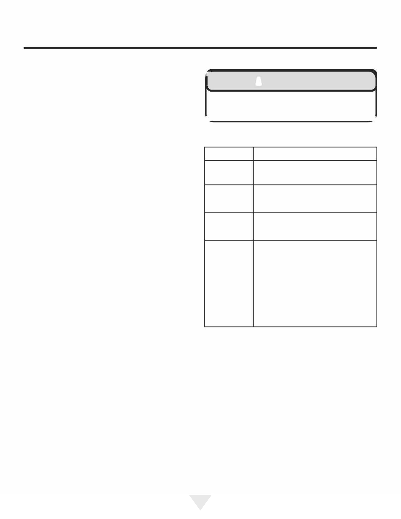
P『oblem
Possible Cause and Remedy
Interior Light
Does Not
Ensure the unit is plugged in and cooling.
Illuminate
Unit Develops
Fst on
Ensure the door is closing and sealing
Internal
pperly.
Suaces.
Unit Develops
The unit is exposed to excessive
Condensation
on External
humidity. Moisture will dissipate as
Suaces.
humidity levels decrease.
Air temperature does not indicate
pduct temperature. See CHECKING
PRODUCT TEMPETURE below.
Adjust the temperature to a cooler set
point. Ensure unit is not located in excessive
Pduct is Not
ambient temperatures or in direct
Cold Enough
sunlight. Ensure the door is closing and sealing
pperly. Ensure the interior light has not
remained on too long. Ensure nothing is blocking
the front grille, und at the boom of the unit.
Ensure the condenser coil is clean and
free of any di or lint build-up.
•
Compressor: The compressor makes a hum or pulsing
sound that may be heard when it operates.
•
Evaporator:
Refrigerant flowing through an evaporator
may sound like boiling liquid.
•
Condenser Fan: Air moving through a condenser may
be heard.
•
Automatic Defrost Drain Pan: Water may be heard
dripping or running into the drain pan when the unit is
in the defrost cycle.
16
17
17
TROUBLESHOOTING
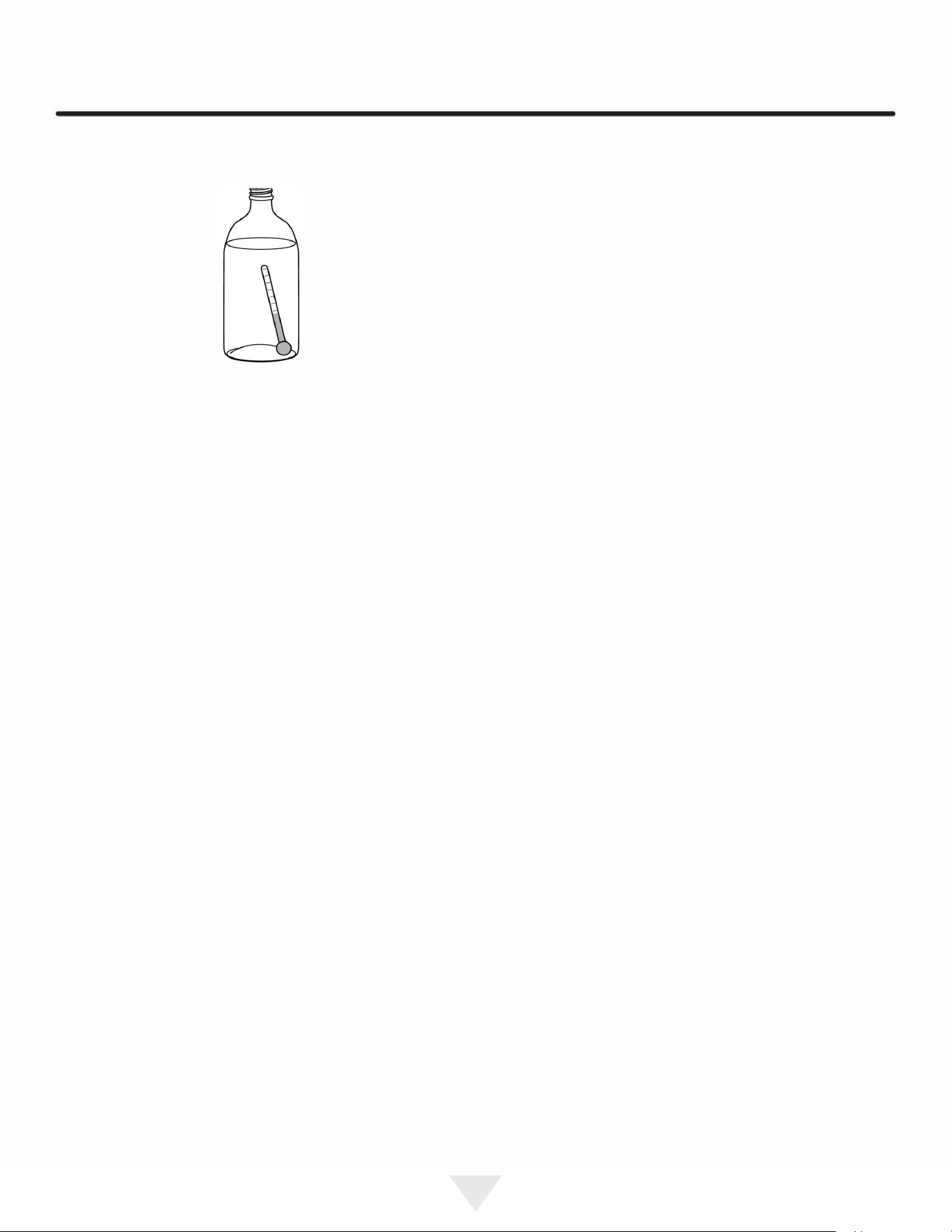
Checking Product Temperature
To check the actual product temperature in the unit:
1.
Partially fill a plastic (nonbreakable) bottle with water
2.
Insert an accurate thermometer.
3.
Tighten the bottle ca
p securely.
4.
Place the bottle in the desired area for 24 hours.
5. Avoid opening the unit during the testing period.
6. Aer 24 hours, check the temperature of the water.
If required, adjust the temperature control in a small
increment (see Control Operation).
Causes which aect the internal tem
peratures of the
cabinet include:
•
Temperature setting.
•
Ambient temperature where installed.
•
Installation in direct sunlight or near a heat source.
17
•
The number of door openings and the time the door is
open.
•
The time the internal light is illuminated. (This mainly
aects product on the top rack or shelf.)
•
Obstruction of front grille or condenser
18
18
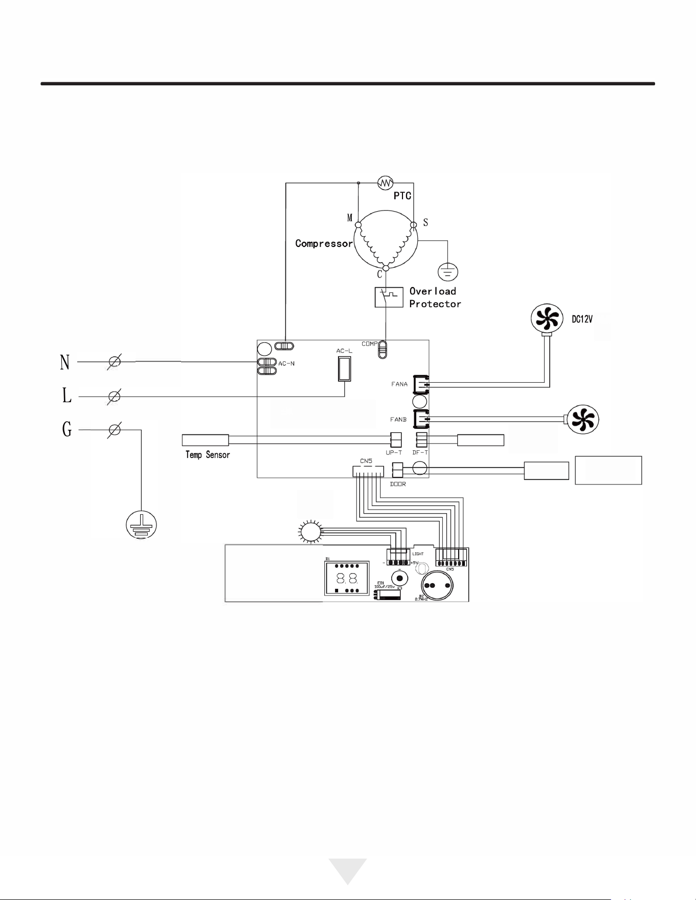
WIRE DIAGRAM
Startor
N
L
G
DC12V
LIGHT@ •
K
,
〈 〈K2
QRSDISVl.0
aol,
,
aa6
18
19
19

PRODUCT LIABILITY
Field service technicians are authorized to make an initial
assessment in the event of reported damages. If there are
any questions about the process involved, the technician
should call Marvel for further explanation.
While inspecting for defects or installation issues, photos
should be taken to document any damages or issues
found.
During the assessment, if the service technician is able to
find the source of the damage and it can be resolved by
replacement of a part, the servicer is authorized to replace
the part in question. The part that caused the damage
must be returned to Marvel in its entirety. The part must
be clearly labeled with the serial number of the unit it was
removed from, the date, and the servicer who removed the
part.
If the service technician determines the damage is the
result of installation issues (water connection/drain, etc.),
the consumer would be notified and the issues shall be
resolved at the direction of the consumer.
If damage is evident and the service technician is
unable to find the source, Marvel must be contacted at
616.754.5601 for further direction.
1260 E. Van Deinse St. • Greenville, Ml 48838
T: 616.754.5601
19
20
20

RRANTY CLAIMS
Before Calling for Seice
The following information defines the parameters for filing a
warranty claim:
•
lid serial number needed
•
lid model number needed
•
Claims must be submitted online at
www.marvelservice.com
•
60 day submittal deadline from date of completed
service
•
Only one repair or unit per warranty claim
•
Part order numbers will be re
quired when submitting r
warranty labor
Units must be registered prior to warranty submittal
Customers may register at www.marvelrefrigeration
.com/warranty-registration. A proof of purchase is re
quired.
We also accept the following information to update warranty:
•
New construction occupancy documents
•
Closing papeork
•
Final billing - Remodel
Warranty parts will be shipped at no charge aer Marvel
confirms warranty status. Please provide the model, serial
number, part number and part description. Some parts will
require color or voltage information.
20
21
21
ORDERING REPLACEMENT PARTS
Parts may be ordered online at partsformarvel.com.
Or contact:
Phone Number: (616) 754-5601
(
NOTE
)
Use only genuine Marvel replacement parts. The
use of non-Marvel parts can reduce performance,
damage the unit, and void the warranty.
Warranty parts will be shipped at no charge aer Marvel
confirms warranty status. Please provide the model, serial
number, part number and part description. Some parts will
require color or voltage information.
Marvel requires the return of original parts, we will inform
you when the parts order is taken. This requirement will
be noted on your packing list. A prepaid shipping label will
be emailed to you. Please enclose a copy of the parts
packing list and be sure the model and serial numbers are
legible on the paperwork. Tag the part with the reported
defect.
Customers and non-authorized servicers may order non
warranty parts at www.partsformarvel.com. Authorized
servicers with a servicer login may order non-warranty
parts at www.marvelservice.com
21
22
22
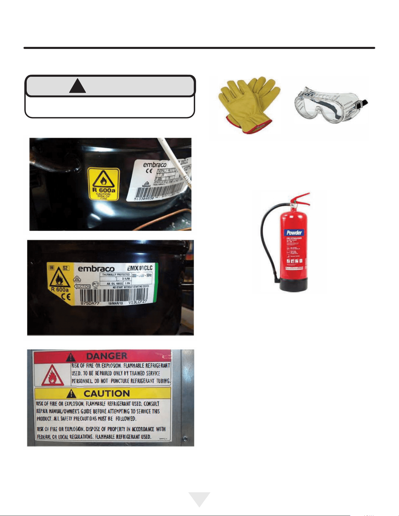
R600A Specications & Handling
!
WARNING
Flammability warnings for a pure-iso-butane
refrigerant.
Gloves and Eye Protection must be used.
R-600a is considered non-toxic, but is ammable when
mixed with air.
Keep a dry powder type re extinguisher in the work area.
R-600a is heavier than air, do not allow any leakage/migra-
tion to low areas such as basements and stairs.
Never use a torch on a fully charged refrigeration system.
Never substitute Marvel OEM replacement parts or
methods of construction.
R-600a must be stored and transported in approved
containers.
23
24
!
WARNING
Only skilled and well trained service technicians
permitted to service R-600a equipped products.
All tools and equipment must be approved for use with
R-600a refrigerant.
Local, state and federal laws, standards must be
observed along with proper certication and licensing.
Ventilation is required during servicing.
No conversions to R-600a from any other refrigerants.
OEM R-600a equipped unit only.
Service area must be free of ignition sources.
No smoking is allowed in the service area.
All replacement electrical components must be OEM
and installed properly (sealed and covered).
If the evaporator is cold prior to service, it must be
thawed prior to service.
When using a vacuum pump, start pump before
opening refrigeration system.
Vacuum pump and recovery equipment should be at
least 10 feet from the work area.
It is recommended that a simple LPG gas detector is
on site during service.
Ensure that all R-600a is removed from the system
prior to brazing any part of the sealed system.
Only a clean, dry leak free system should be charged
with R-600a.
R-600A Specications/Labeling
R-600a equipped products are labeled (both the unit and
the compressor).
R-600a is colorless and odorless.
R-600a is considered non-toxic, but is ammable when
mixed with air.
Do not remove or alter any R-600a labeling on the product.
Use only a refrigerant grade R-600a from a properly
labeled container.
Recovering/Reclaiming R-600A
(R-600a has been exempted from recovery/reclaiming
requirements by the US EPA)
Recovery/Reclaiming equipment must be approved for use
with R-600a.
Ensure the evaporator is at room temperature prior to
recovery/reclaiming R-600a.
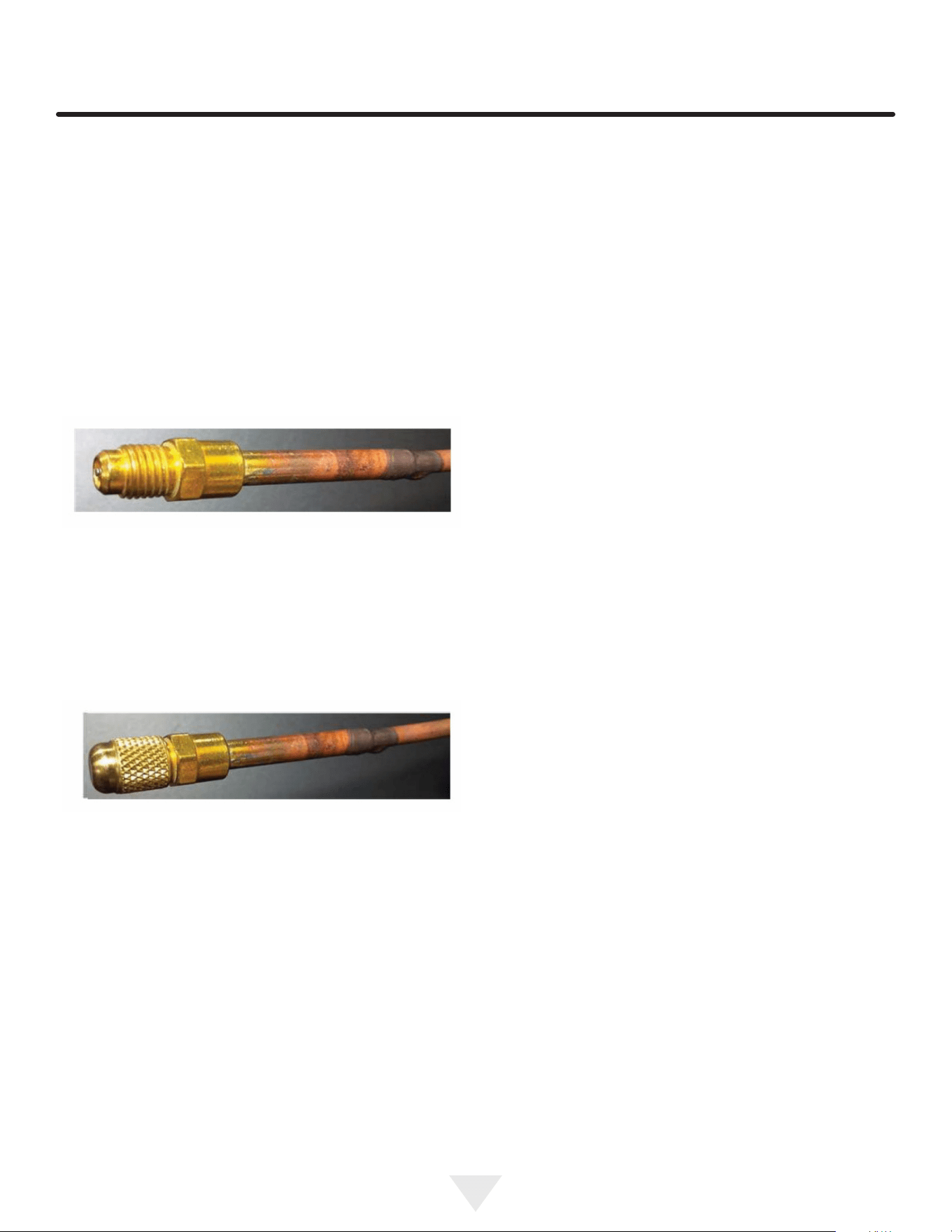
Use a common piercing pliers or piercing valve to remove
R-600a from the compressor process tube. (Note: Pierc-
ing devices must not be left on the system and must be
replaced with a Schrader type valve).
25
Evacuate/reclaim via the piecing pliers to ensure the
system is empty of R-600a before any system work is
performed.
The recovery cylinder must be evacuated (no air inside)
prior to accepting R-600a.
The recovery cylinder must not be lled more than 45%
safe ll level and refrigerants must not be mixed.
The recovery cylinder must be clearly marked with R600a
and Flammable Warning labels.
Ensure proper ventilation during recovery/reclaiming of
R600a.
Start vacuum pump/recovery pump prior to piercing the
compressor process tube.
Follow recovery/reclaim OEM instructions for the specic
equipment used.
System Repair
Ensure no residual R-600a refrigerant is left within the
system prior to repair (simple venting is not sucient).
Evacuate and charge with dry nitrogen for leak checks.
Repair leaks or replace system parts as required.
When re-brazing, the system must be purged with
dry nitrogen and at least one access point open to the
atmosphere.
When re-brazing, proper ventilation is required along with
constant monitoring for the presence of R600a refrigerant.
The lter dryer must be replaced any time the sealed
system is serviced.
No system should be open to the atmosphere for longer
than 15 minutes to avoid moisture migration into the system
components.
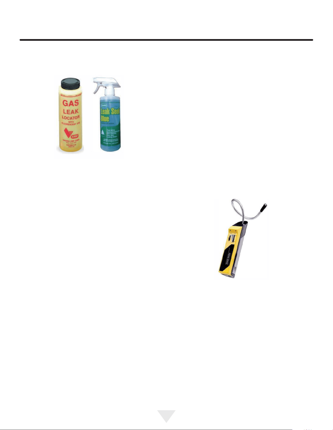
Leak Detection
After removal of the R-600a, the unit can be charged with
dry nitrogen or helium.
Electronic leak detection or soap solution can be used
tocheck for nitrogen/helium leaks.
Never use a halide torch or lighted match to check the
system for leaks at any time.
The high side of the refrigeration system (compressor
discharge to outlet of drier) must be leak tested with the
compressor running.
26
The low side of the refrigeration system (evaporator,
compressor and suction line) must be leak tested with the
compressor o (equalized pressure).
Recharging
No air is ever to be allowed inside the refrigeration system
(R-600a refrigerant or dry nitrogen only).
Never use a torch on a fully charged refrigeration system.
Install a Schrader Type access port on the compressor
process stub.
Evacuate the system to 100 microns prior to charging.
Weigh in the R-600a charge using a refrigerant scale (run
compressor an extra two minutes to clear the charging
hoses).
Seal the Schrader Type access port, a proper cap and seal
must be used to close the system.
Summary
Safely handling R-600a requires proper procedures and
training.
R-600a approved service tools must be used.
R-600a labeling must not be removed or altered.
Proper ventilation during service is required.
Never apply a torch to a charged R-600a refrigeration
system.
Use OEM replacement service parts and do not alter the
construction of the unit.
Proper ventilation during service is required.
Never apply a torch to a charged R600a refrigeration
system.
Use OEM replacement service parts and do not alter the
construction of the unit.
No air is ever to be allowed inside the refrigeration system
(R600a refrigerant or dry nitrogen only).
Never use a torch on a fully charged refrigeration system.
Install a Schrader Type access port on the compressor
process stub.
The lter dryer must be replaced any time the sealed sys-
tem is serviced.
No system should be open to the atmosphere for longer
than 15 minutes to avoid moisture migration into the system
components.
Leak Detection
After removal of the R600a, the unit can be charged with
dry nitrogen or helium.
Electronic leak detection or soap solution can be used to
check for nitrogen/helium leaks. Evacuate and charge with
dry nitrogen for leak checks.

27
ENSURING YOUR WARRANTY STAYS VALID
CLEANING AND MAINTENANCE
• Clean the Condenser Every Six Months
Failure to keep the condenser clean can result in permanent damage to the compressor.
The condenser coil is located near the compressor and usually at the bottom of the machine. In order for the condenser to perform
eciently, it must be cleaned about every six months to remove dust and debris and prevent overheating.
• Deep Clean the Ice Machine Every Six Months
Neglecting this cleaning will lead to mold or mildew buildup, cloudy ice, reduced water ow, reduced ice production,
and damage to the machine.
Use only manufacturer-approved, nickel-safe ice machine cleaner and follow all label warnings and
directions.
Order ice machine cleaner online: www.u-line.com Part # 80-55667-00.
Every six months the ice machine requires a thorough cleaning to remove debris from the bin and ush out impurities that accumulates
from the water supply; clear, craft, and nugget machines are equipped with a built-in cleaning cycle.
• Clean Stainless Steel Surfaces
Your machine is built with quality stainless steel, but it can still rust when not properly maintained.
- Avoid exposure to outdoor elements such as rain, snow, sprinklers or pool splash.
- Use only a non-chlorine, non-abrasive stainless steel cleaner.
- Inspect the machine for any signs of rust. When spotted early, the rust is only on the surface and can usually be scrubbed o.
SAFE INSTALLATION AND MAINTENANCE
• Outdoor Operation
Only machines designed for outdoor use may be operated outdoors.
- The machine should be installed under cover, to avoid exposure to rain, snow, and direct sun.
- The machine should not be not be exposed to chlorinated water such as from pool or hot tub splash.
- Do not operate in temperatures below 45°F (7°C) or above 100°F (38°C).
• Indoor Operation
- Install where the machine will not be exposed to direct sunlight - especially if the appliance a glass door.
- Do not install the machine where it will be exposed to chlorinated water such as from an indoor pool or hot tub splash.
- Do not operate in temperatures below 50°F (10°C) or above 100°F (38°C).
• Location and Ventilation
- Do not block the grille on the front base of the machine; proper airow is essential to cooling.
- Do not operate the appliance inside a cabinet; it has been designed to operate under a counter or free-standing (certain models only).
• Proper Sealing - Beverage Dispensers
- If not sealed properly, excessive condensation, limited cooling, and damage to the machine will occur. When correctly installed, the
insulation should extend from within the refrigerator, through the counter, and into the tap tower.
ELECTRICAL AND DRAINAGE REQUIREMENTS
• Operate With a Safe Electrical Connection
Only operate the appliance on a dedicated circuit to avoid power uctuations and overloads.
- Do not use an extension cord. Only the supplied power cord directly connected to an outlet ensures that the machine will safely receive
adequate power. Extension cords can become unplugged accidentally, overheat, or become damaged. Improper electrical connection will
void the warranty.
• Operate With Proper Drainage
If your appliance requires a drain hookup consult a plumber for proper installation. Improper drainage can cause damage to the machine
as well as its surroundings. Improper drainage will void the warranty.
CAUTION
!
CAUTION
!
CAUTION
!
CAUTION
!
CAUTION
!
CAUTION
!

28
Middleby Refrigeration | 1260 E. Van Deinse, Greenville, MI 48838
Middleby Refrigeration Limited Warranty
ONE YEAR LIMITED PARTS & LABOR WARRANTY – Northland Collection
For one year from the date of original purchase, this warranty covers all parts and labor to repair or replace any part of the
referenced Middleby Refrigeration product (the “Equipment”) that under normal use proves to be defective in materials or
workmanship. For products installed and used for normal residential use, material cosmetic defects are included in this warranty,
with coverage limited to 60 days from the date of original purchase. This warranty is conditioned upon you promptly notifying
Middleby Refrigeration of any claims and providing Middleby Refrigeration with all data and information requested by Middleby
Refrigeration or its service agents in connection with such claims as well as all necessary access to your premises and the
Equipment. All service provided by Middleby Refrigeration under the above warranty must be performed by a Middleby
Refrigeration factory authorized servicer, unless otherwise specified by Middleby Refrigeration. Service provided during normal
business hours.
TWO YEAR LIMITED PARTS & LABOR WARRANTY – Essential, Home, Seamless Collections and Merit Ice machines
For two years from the date of original purchase, this warranty covers all parts and labor to repair or replace any part of the
referenced Middleby Refrigeration product (the “Equipment”) that under normal use proves to be defective in materials or
workmanship. For products installed and used for normal residential use, material cosmetic defects are included in this warranty,
with coverage limited to 60 days from the date of original purchase. This warranty is conditioned upon you promptly notifying
Middleby Refrigeration of any claims and providing Middleby Refrigeration with all data and information requested by Middleby
Refrigeration or its service agents in connection with such claims as well as all necessary access to your premises and the
Equipment. All service provided by Middleby Refrigeration under the above warranty must be performed by a Middleby
Refrigeration factory authorized servicer, unless otherwise specified by Middleby Refrigeration. Service provided during normal
business hours.
THREE YEAR LIMITED PARTS & LABOR WARRANTY – Merit Collection excluding ice machines
For three years from the date of original purchase, this warranty covers all parts and labor to repair or replace any part of the
referenced Middleby Refrigeration product (the “Equipment”) that under normal use proves to be defective in materials or
workmanship. For products installed and used for normal residential use, material cosmetic defects are included in this warranty,
with coverage limited to 60 days from the date of original purchase. This warranty is conditioned upon you promptly notifying
Middleby Refrigeration of any claims and providing Middleby Refrigeration with all data and information requested by Middleby
Refrigeration or its service agents in connection with such claims as well as all necessary access to your premises and the
Equipment. All service provided by Middleby Refrigeration under the above warranty must be performed by a Middleby
Refrigeration factory authorized servicer, unless otherwise specified by Middleby Refrigeration. Service provided during normal
business hours.
LIMITED SIX YEAR SEALED SYSTEM PARTS WARRANTY – Essential, Home, Seamless and Merit Collections
For six years from the date of original purchase, Middleby Refrigeration will cover the following parts only (no labor) if they prove to
be defective under normal residential use: compressor. This warranty is conditioned upon you promptly notifying Middleby
Refrigeration of any claims and providing Middleby Refrigeration with all data and information requested by Middleby Refrigeration
or its service agents in connection with such claims.
WARRANTY TERMS
These warranties apply only to Equipment installed in any one of the fifty states of the United States, the District of Columbia, or
the ten provinces of Canada. The Equipment must be installed, operated, and maintained in accordance with Middleby

29
Middleby Refrigeration | 1260 E. Van Deinse, Greenville, MI 48838
Refrigeration Brand User Guides, copies of which were provided to you with the Equipment or otherwise will be furnished to you
upon request. Further, this warranty applies only to Equipment shipped from the Middleby Refrigeration facility after July 1, 2025,
and purchased from an authorized dealer.
Except as provided in the Limited Warranty above, the Equipment is provided “as-is”. Middleby Refrigeration claims all other
warranties, express, statutory or implied, including without limitation, the implied warranties of title, non-infringement,
merchantability and fitness for a particular purpose. Middleby Refrigeration does not warrant that the Equipment will meet your
specifications or needs. You acknowledge that you are solely responsible for the selection of the Equipment and determining the
suitability of the Equipment for your needs.
Any warranty that may be implied in connection with your purchase or use of the product, including any warranty of
merchantability or any warranty that fits for a particular purpose is limited to the duration of these warranties. Some states do not
allow limitations on how long an implied warranty lasts, so the above limitations may not apply to you.
The warranties only apply to the original purchaser and are non-transferable.
The warranties apply to units operated outside only if designed for outdoor use by model and serial number.
Replacement water filters, light bulbs, and other consumable parts are not covered by these warranties.
The start of Middleby Refrigeration’s obligation is limited to four years after the shipment date from Middleby Refrigeration.
In-home instruction on how to use your product is not covered by these warranties.
Food, beverage, and medicine loss are not covered by these warranties.
If the Equipment is located in an area where Middleby Refrigeration factory authorized service is not available, you may be
responsible for a trip charge or you may be required to bring the Equipment to a Middleby Refrigeration factory authorized
service location at your own cost and expense.
Units purchased after use as floor displays, and/or certified reconditioned units, are covered by the limited one-year warranty
only and no coverage is provided for cosmetic defects.
Signal issues related to Wi-Fi connectivity are not covered by these warranties.
Equipment that is not installed, operated and maintained in accordance with Middleby Refrigeration’s Use and Care Manual
or other written materials provided to you by Middleby Refrigeration or available for the Equipment (as may be updated by
Middleby Refrigeration from time to time, the “Manual”), a copy of which is provided to you with the Equipment or otherwise
will be furnished to you upon request, is excluded from this warranty. This warranty does not apply to damage or failure which
results, in Middleby Refrigeration’s or its service agent’s sole opinion, from failure to provide a suitable installation and
operating environment (including power and HVAC if applicable) and facilities as prescribed by the Manual, misuse, abuse,
accident or improper use, neglect, power failure or power surges (over or under voltage), or to damage or failure from flood,
fire, lightning or other natural or man-made disasters, or other Acts of God, or to Equipment that has missing or altered serial
numbers.
Modifications and Repair: Equipment that has been modified or altered by persons other than Middleby Refrigeration’s or its
service agents, or Equipment that has had non-approved devices or connection items attached thereto, is excluded from
coverage under this warranty. Repair of the Equipment by anyone other than Middleby Refrigeration’s or its authorized service
agents will void all warranties on the Equipment.

30
Middleby Refrigeration | 1260 E. Van Deinse, Greenville, MI 48838
Accessories: Accessories and parts (collectively “Accessories”) that are consumed in the normal course of Equipment
operation or maintenance are excluded from this warranty. Failure of or damage to Equipment or components from the use of
non-approved cleaning chemicals, devices or processes is also excluded from this warranty.
Warranty Service, Exclusive Remedy
Middleby Refrigeration will be solely responsible for determining whether or not the Equipment or any component thereof is
defective. Defective components covered by this warranty will be repaired or replaced at Middleby Refrigeration’s option
without charge to you and such repaired or replacement components will be covered by this warranty for the balance of the
Warranty Period. Parts used in the repair of defective components and replacement components may be new, recovered or
rebuilt. At its sole option, Middleby Refrigeration may decide to replace defective Equipment covered by this warranty with
new, recovered or rebuilt Equipment of equal or greater capability, and such Equipment will be covered by this Limited
Warranty for the balance of the Warranty Period. Defective Equipment and components will become the property of Middleby
Refrigeration. This paragraph states Middleby Refrigeration’s sole and exclusive obligation and liability and your sole and
exclusive remedy under this warranty. Middleby Refrigeration shall not be responsible for a failure to provide warranty
services due to causes beyond Middleby Refrigeration’s or its service agents’ control.
Warranty Claims
Claims under this warranty must be reported to Middleby Refrigeration under such reporting service as Middleby Refrigeration
may designate. Upon receipt of the claim and related information and preliminary verification that the claim is valid, Middleby
Refrigeration will promptly notify an authorized service agent to contact you and arrange for an on-site repair visit during the
service agent’s normal working hours. Any costs incurred by Middleby Refrigeration or its service agent associated with a
service agent being refused or unable to gain access to the Equipment on your premises, or a claim not covered by this
warranty, will be charged to you.
Disclaimer of Damages
Middleby Refrigeration disclaims all incidental, special and consequential damages, including but not limited to loss of use,
lost revenue or profits, or substitute use, suffered by you or any third party, whether arising in contract, tort (including
negligence), or otherwise, resulting from any breach by Middleby Refrigeration or its service agents of this warranty, or
resulting from the manufacture, use, or defects, of or in the Equipment, even if Middleby Refrigeration was apprised of the
possibility of such damages.
Customer Indemnity
You agree to indemnify, defend and hold Middleby Refrigeration harmless from all third-party claims, demands, judgments,
fees and costs directly or indirectly arising out of or related to your use of the Equipment. You further agree to indemnify and
hold Middleby Refrigeration harmless from any incidental, consequential or special damage suffered by you, including lost
revenue or profits, loss of use, or substitute use, during periods of Equipment failure or loss of use.
Governing Law, Entire Warranty
This warranty shall be governed and construed in accordance with the laws of the State of Michigan, USA (except with respect
to its provisions regarding conflicts of laws). The warranty described herein is the complete and only warranty for Equipment
and supersedes all prior oral or written agreements and understandings that may have existed between us relating to
Equipment warranties. The terms of this warranty may not be altered, amended or modified except by a signed writing from
Middleby Refrigeration. Any purported alteration, amendment or modification by a service agent or anyone else will not be
enforceable against Middleby Refrigeration.

31
Middleby Refrigeration | 1260 E. Van Deinse, Greenville, MI 48838
Charges for Non-Warranty Service or Rejection of Service Visit
In the event that repairs, replacement or service are provided by Middleby Refrigeration’s service agents for work not covered
by this limited warranty, customers agree to pay the service agent directly according to the service agent’s normal scale of
charges. In the event Middleby Refrigeration is invoiced by the service agent for services not covered under this extended
warranty, Middleby Refrigeration will invoice customer, and customer will pay such invoice based on terms of net 10 days.
Customer also agrees to pay any cost incurred by Middleby Refrigeration or its service agent associated with a service agent
responding to a call for service but then being refused or unable to gain access to the Equipment on Customer’s premises.
Failure to submit payment may, at Middleby Refrigeration’s discretion, result in Middleby Refrigeration voiding the balance of
the warranty. In no event will Middleby Refrigeration authorize a customer with an outstanding Non-Warranty invoice.
For parts and service assistance, or to find factory authorized service near you, contact Middleby Refrigeration at
616.754.5601.

32
3633