R
DURASTAR.COM 1
Model Number:
Serial Number:
Purchase Date:
Installing Contractor Company Name:
TIP
Capture relevant information about your Durastar mini-split equipment before it is
installed and write it above for future reference.
OWNER'S MANUAL
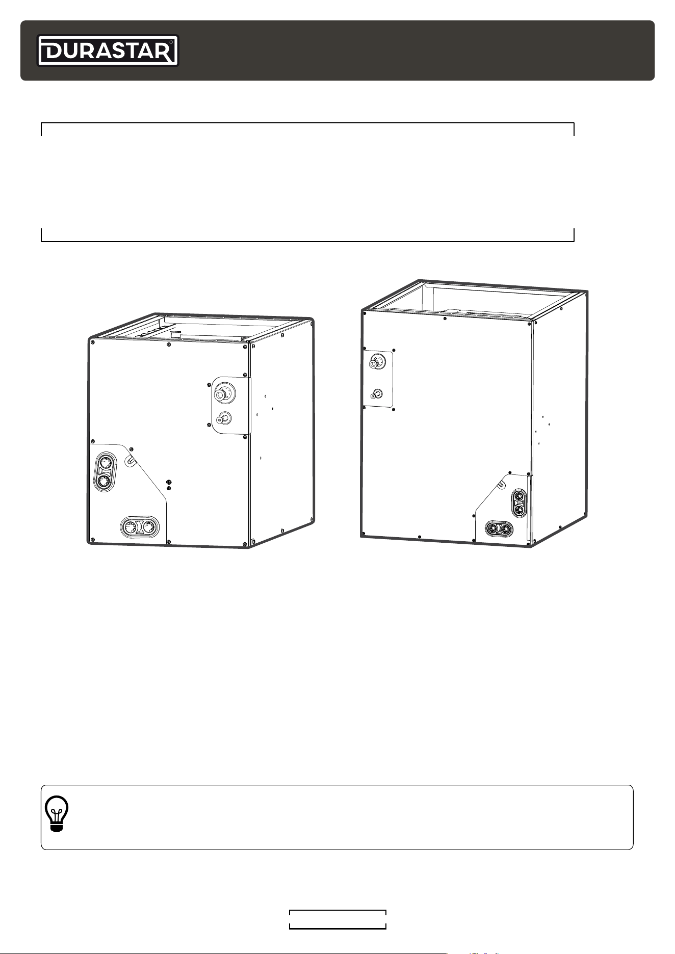
EVAPORATOR COIL 18K - 60K BTU
DRUC2414S2A, DRUC2417S2A, DRUC3614S2A, DRUC3617S2A,
DRUC3621S2A, DRUC6021S2A, DRUC6024S2A
R
DURASTAR.COM2
TABLE OF CONTENTS
TABLE OF CONTENTS ....................................................................................................................................2
INTRODUCTION ..................................................................................................................................................3
SYMBOLS USED IN THIS MANUAL ...........................................................................................................3
IMPORTANT SAFETY PRECAUTIONS ....................................................................................................4
INCLUDED ACCESSORIES ...........................................................................................................................16
OPERATION TEMPERATURES ...................................................................................................................17
CARE AND MAINTENANCE .........................................................................................................................18
TROUBLESHOOTING ......................................................................................................................................19
LIMITED WARRANTY - PARTS.................................................................................................................. 22
R
DURASTAR.COM
3
INTRODUCTION
To better serve you, please do the following before contacting customer service:
• If you received a damaged product, immediately contact the retailer or dealer that sold you the
product.
• Read and follow this manual carefully to help you use and maintain your coil.
• Read the troubleshooting section of this manual as it will help you diagnose and solve common
issues.
• Visit us on the web at www.durastar.com to download product guides and up-to-date
information.
• If you need warranty service, our friendly customer service representatives are available via
email at [email protected] or by telephone at 1-888-320-0706.
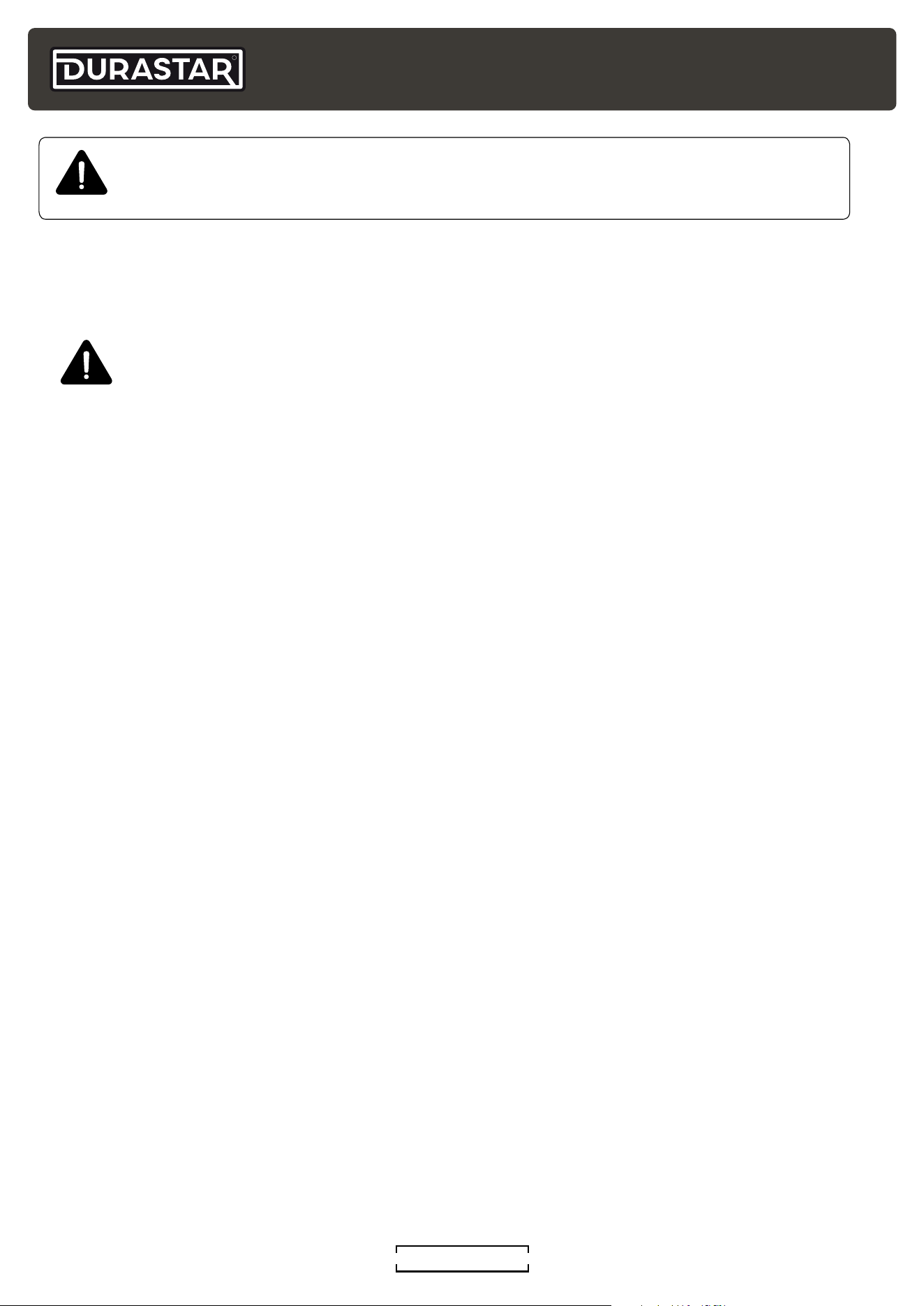
WARNING: The warning symbol indicates personal injury or loss of life is possible. Extra
care and precautions should be taken to ensure the user's safety.
CAUTION: The caution symbol indicates property damage or other serious
consequences could occur.
NOTE: The pencil indicates any manufacturer notes relating to surrounding content.
These may include further clarications or call-outs.
TIP: A light bulb symbol indicates suggested manufacturer tips for the user to get the
most out of the Durastar equipment and to accommodate the best user experience.
SYMBOLS USED IN THIS MANUAL
WARNING:
RISK OF FIRE DUE TO FLAMMABLE
MATERIALS
Follow handling instructions carefully
in compliance with national regulations.
Explanation of symbols displayed on the unit
CAUTION
This symbol shows that the operation manual should be read carefully.
CAUTION
This symbol shows that a service personnel should be handling this equipment
with reference to the installation manual.
CAUTION
This symbol shows that information is available such as the operating
manual or installation manual.
R-454B
A2L
Refrigerant
Safety Group
A2L
R
DURASTAR.COM4
IMPORTANT SAFETY PRECAUTIONS
Improper handling can cause serious damage or injury. Please read the following safety
information in its entirety.
Operation, Cleaning, and Maintenance Safety Precautions
• Children and people with reduced physical, sensory, or mental capabilities, or lack of
experience and knowledge, should only use, clean, or maintain this air conditioner if they
are given supervision or instructions concerning use of the air conditioner in a safe way and
understand the hazards involved. Children should not play with the air conditioner.
• Maintenance or repair must be performed by qualied professionals. Otherwise, you may
experience personal injury or damage to the air conditioner and surrounding property.
• Disconnect the power supply by turning it off at the circuit breaker when cleaning, maintaining,
or repairing the air conditioner. Otherwise, you could risk electric shock.
• When turning the unit on or off via the emergency operation switch, press the switch with an
insulated object other than metal.
• If the below problems occur, please turn off the air conditioner and disconnect power at the
circuit breaker immediately. Then contact your dealer or a qualied professional for service.
- The power cord is overheating or damaged.
- There is an abnormal sound during operation.
- The circuit breaker trips frequently.
- The air conditioner gives off a burning smell.
- The indoor unit is leaking.
• Do not block the air outlet or air inlet. This could cause a malfunction.
• Never stick ngers or any other body parts into the air conditioner openings. The internal fan
may be rotating at high speeds, and may result in injury.
• Do not spill water on the remote control as this can permanently damage the remote.
• Do not spray water on the indoor unit. This could cause electric shock or a unit malfunction.
• Do not clean the air conditioner with excessive amounts of water.
• Do not clean the air conditioner with combustible cleaning agents; they can cause re or
deformation.
• After removing the lter, do not touch the ns in order to avoid injury.
• Do not use re or a hair dryer to dry the lter. This could cause a deformation or re hazard.
• Do not step on the top panel of the unit, or put heavy objects on the top panel. This could
cause damage or personal injury.
• Do not use ammable materials such as hair spray, lacquer, or paint near the air conditioner as
they may catch re.
• Do not operate the air conditioner in places near combustible gases. Emitted gases may
collect around the air conditioner and cause an explosion.
• Do not operate your air conditioner in a wet room such as a bathroom or laundry room. Too
much exposure to water can cause electrical components to short circuit.
• If the air conditioner is used together with burners or other heating devices, thoroughly
ventilate the room to avoid oxygen deciency.
WARNING
Turn off the air conditioner and disconnect the power before installing, cleaning, or
repairing the air conditioner. Failure to do so can cause electric shock.
R
DURASTAR.COM
5
Electrical Safety
• Do not modify the length of the power supply cord or use an extension cord to power the unit.
• If the supply cord is damaged, it must be replaced by the manufacturer, a service agent, or a
similarly qualied person in order to avoid a safety hazard.
• Keep power plug clean. Remove any dust or grime that accumulates on or around the plug.
Dirty plugs can cause re or electric shock.
• Do not pull power cord to unplug unit. Hold the plug rmly and pull it from the outlet. Pulling
directly on the cord can damage it, which can lead to re or electric shock.
• Do not share the electrical outlet with other appliances. Improper or insufcient power supply
can cause re or electrical shock.
• The product must be properly grounded at the time of installation, or electrical shock may
occur.
• For all electrical work, follow all local and national wiring standards and regulations. Connect
cables tightly, and clamp them securely to prevent external forces from damaging the
terminal. Improper electrical connections can overheat and cause re, and may also cause
shock. All electrical connections must be made according to the Electrical Connection
Diagram located on the panels of the indoor and outdoor units.
• All wiring must be properly arranged to ensure that the control board cover can close properly.
If the control board cover is not closed properly, it can lead to corrosion and cause the
connection points on the terminal to heat up, catch re, or cause electrical shock.
• If connecting power to xed wiring, an all-pole disconnection device which has at least 3mm
clearances in all poles, and have a leakage current that may exceed 10mA, the residual
current device(RCD) having a rated residual operating current not exceeding 30mA, and
disconnection must be incorporated in the xed wiring in accordance with the wiring rules.
• The air conditioner’s circuit board (PCB) is designed with a fuse to provide over-current
protection. The specications of the fuse are printed on the circuit board.
Installation Safety
• Installation must be performed by an authorized dealer or specialist. Improper installation
can cause water leakage, electrical shock, or re. (In North America, installation must be
performed in accordance with NEC and CEC requirements by authorized personnel only.)
• Installation must be performed according to the installation instructions. Improper installation
can cause water leakage, electrical shock, or re.
• This air conditioner shall be installed in accordance with national and local wiring regulations.
• Contact an authorized service technician for repair or maintenance of this unit.
• Only use the included accessories, parts, and specied parts for installation. Using non-
standard parts can cause water leakage, electrical shock, re, and can cause the unit to fail.
• Install the unit in a rm location that can support the unit’s weight. If the chosen location
cannot support the unit’s weight, or the installation is not done properly, the unit may fall and
cause serious injury and damage.
• Install drainage piping according to the instructions in the installation manual. Improper
drainage may cause water damage to your home and property.
• For units that have an auxiliary electric heater, do not install the unit within 3 feet (1 meter) of
any combustible materials.
• Do not install the unit in a location that may be exposed to combustible gas leaks. If
combustible gas accumulates around the unit, it may cause a re.
R
DURASTAR.COM6
• Do not turn on the power until all work has been completed.
• When moving or relocating the air conditioner, consult experienced service technicians for
disconnection and re-installation of the unit.
• Be careful when opening or closing valves below freezing temperatures. Refrigerant may spurt
out from the gap between the valve stem and the valve body, resulting in injuries.
WARNING: REFRIGERANT SAFETY (A2L)
• Do not use means to accelerate the defrosting process or to clean the unit, other
than those recommended by the manufacturer.
• The appliance shall be stored in a room without continuously operating ignition
sources (for example: open flames, an operating gas appliance or an operating
electric heater).
• Do not pierce or burn.
• Be aware that flammable refrigerants may not contain an odor.
• Compliance with national refrigerant regulations shall be observed.
1. Installation (Where Refrigerant Pipes Are Allowed)
• Any person who is involved with working on or breaking into a refrigerant circuit should hold a
current valid certicate from an industry-accredited assessment authority, which authorizes
their competence to handle refrigerants safely in accordance with an industry recognized
assessment specication.
• Maintenance and repair requiring the assistance of other skilled personnel shall be carried out
under the supervision of the person competent in the use of ammable refrigerants.
• That the installation of pipe-work shall be kept to a minimum.
• That pipe-work shall be protected from physical damage.
• Where refrigerant pipes shall be compliance with national gas regulations.
• That mechanical connections shall be accessible for maintenance purposes.
• Be more careful that foreign matter(oil, water,etc) does not enter the piping. Also, when
storing the piping, securely seal the opening by pinching, taping, etc.
• All working procedure that affects safety means shall only be carried by competent persons.
• Appliance shall be stored in a well ventilated area where the room size corresponds to the
room area as specic for operation.
• Joints shall be tested with detection equipment with a capability of 0.18 oz (5 g) per year of
refrigerant or better, with the equipment in standstill and under operation or under a pressure
of at least these standstill or operation conditions after installation. Detachable joints shall
NOT be used in the indoor side of the unit (brazed, welded joint could be used).
• In cases that require mechanical ventilation, ventilation openings shall be kept clear of
obstruction.
LEAK DETECTION SYSTEM installed. Unit must be powered except for service. For the unit with
refrigerant sensor, when the refrigerant sensor detects refrigerant leakage, the indoor unit will
display a error code and emit a buzzing sound, the compressor of outdoor unit will immediately
stop, and the indoor fan will start running. The service life of the refrigerant sensor is 15 years.
When the refrigerant sensor malfunctions, the indoor unit will display the error code “FHCC”. The
refrigerant sensor can not be repaired and can only be replaced by the manufacturer. It shall only
be replaced with the sensor specied by the manufacturer.
A2L REFRIGERANT SAFETY PRECAUTIONS
R
DURASTAR.COM
7
2. Because a FLAMMABLE REFRIGERANT is used, the requirements for installation
space of appliance and/or ventilation requirements are determined according to:
• the mass charge amount(M) used in the appliance,
• the installation location,
• the type of ventilation of the location or of the appliance.
• piping material, pipe routing, and installation shall include protection from physical damage
in operation and service, and be in compliance with national and local codes and standards,
such as ASHRAE 15, IAPMO Uniform Mechanical Code, ICC International Mechanical Code, or
CSA B52. All eld joints shall be accessible for inspection prior to being covered or enclosed.
• that protection devices, piping, and ttings shall be protected as far as possible against
adverse environmental effects, for example, the danger of water collecting and freezing in
relief pipes or the accumulation of dirt and debris;
• that piping in refrigeration systems shall be so designed and installed to minimize the
likelihood of hydraulic shock damaging the system;
• that steel pipes and components shall be protected against corrosion with a rustproof coating
before applying any insulation;
• that precautions shall be taken to avoid excessive vibration or pulsation;
• the minimum oor area of the room shall be mentioned in the form of a table or a single gure
without reference to a formula;
• After completion of eld piping for split systems, the eld pipework shall be pressure tested
with OXYGEN-FREE NITROGEN (OFN) and then vacuum tested prior to refrigerant charging,
according to the following requirements:
1. Pressure test the refrigerant piping to 500 PSI.
2. The test pressure after removal of pressure source shall be maintained for at least 1 hour
with no decrease of pressure indicated by the test gauge, with test gauge resolution not
exceeding 5% of the test pressure.
3. During the evacuation test, after achieving a vacuum level specied in the manual or less,
the refrigeration system shall be isolated from the vacuum pump and the pressure shall
not rise above 1500 microns within 10 min. The vacuum pressure level shall be specied in
the manual, and shall be the lessor of 500 microns or the value required for compliance
with national and local codes and standards, which may vary between residential,
commercial,and industrial buildings.
• Field-made refrigerant joints indoors shall be tightness tested according to the following
requirements: The test method shall have a sensitivity of 0.18 oz (5 g) per year of refrigerant or
better under a pressure of at least 125% of the maximum allowable pressure. No leak shall be
detected.
3 . Qualications Of Workers
Any maintenance, service and repair operations must be performed by qualied personnel.
Any working procedure that impacts safety must be performed only by qualied individuals
who have completed the necessary training and obtained certication to demonstrate their
competence. The training of these procedures is carried out by national training organizations
or manufacturers that are accredited to teach the relevant national competency standards that
may be set in legislation. All training shall follow the ANNEX HH requirements of UL 60335-2-40
4th Edition.
Examples for such working procedures are:
• breaking into the refrigerating circuit;
• opening of sealed components;
• opening of ventilated enclosures.
R
DURASTAR.COM8
4. Checks To The Area
Prior to beginning work on systems containing ammable refrigerants, safety checks are
necessary to ensure that the risk of ignition is minimized. For repair to the refrigerating system,
the following precautions shall be complied with prior to conducting work on the system.
5. Work Procedure
Works shall be undertaken under a controlled procedure so as to minimize the risk of a ammable
gas or vapor being present while the work is being performed.
6. General Work Area
All maintenance staff and others working in the local area shall be instructed on the nature of
work being carried out. Working in conned spaces shall be avoided.
7. Checking For Presence Of Refrigerant
The area shall be checked with an appropriate refrigerant detector prior to and during work,
to ensure the technician is aware of potentially ammable atmospheres. Ensure that the leak
detection equipment being used is suitable for use with ammable refrigerants, i.e. no sparking,
adequately sealed or intrinsically safe.
8. Presence Of Fire Extinguisher
If any hot work is to be conducted on the refrigeration equipment or any associated parts,
appropriate re extinguishing equipment shall be available to hand. Have a dry power or CO2 re
extinguisher adjacent to the charging area.
9. No Ignition Sources
No person carrying out work in relation to a REFRIGERATING SYSTEM which involves exposing
any pipe work shall use any sources of ignition in such a manner that it may lead to the risk of re
or explosion. All possible ignition sources, including cigarette smoking, should be kept sufciently
far away from the site of installation, repairing, removing and disposal, during which refrigerant
can possibly be released to the surrounding space. Prior to work taking place, the area around
the equipment is to be surveyed to make sure that there are no ammable hazards or ignition
risks.
“No Smoking” signs shall be displayed.
10. Ventilated Area
Ensure that the area is in the open or that it is adequately ventilated before breaking into the
system or conducting any work that could produce ignition. Keep ventilation openings clear of
obstruction. Ventilation continue during the period that the work is carried out. Proper ventilation
should safely disperse any released refrigerant and preferably expel it externally into the
atmosphere.
11. Checks To The Refrigeration Equipment
Where electrical components are being changed, they shall be t for the purpose and to the
correct specication. At all times the manufacturer’s maintenance and service guidelines shall be
followed. If in doubt consult the manufacturer’s technical department for assistance. The following
checks shall be applied to installations using FLAMMABLE REFRIGERANTS:
R
DURASTAR.COM
9
• the actual refrigerant charge is in accordance with the room size within which the refrigerant
containing parts are installed;
• the ventilation machinery and outlets are operating adequately and are not obstructed;
• if an indirect refrigerating circuit is being used, the secondary circuits shall be checked for the
presence of refrigerant;
• marking to the equipment continues to be visible and legible, marking and signs that are
illegible shall be corrected;
• refrigeration pipe or components are installed in a position where they are unlikely to be
exposed to any substance which may corrode refrigerant containing components, unless the
components are constructed of materials which are inherently resistant to being corroded or
are suitably protected against being so corroded.
12. Checks To Electrical Devices
Repair and maintenance to electrical components shall include initial safety checks and
component inspection procedures. If a fault exists that could compromise safety, then no
electrical supply shall be connected to the circuit until it is satisfactorily dealt with. If the fault
cannot be corrected immediately but it is necessary to continue operation, and adequate
temporary solution shall be used. This shall be reported to the owner of the equipment so all
parties are advised. Initial safety checks shall include:
• that capacitors are discharged: this shall be done in a safe manner to avoid possibility of
sparking;
• that there no live electrical components and wiring are exposed while charging, recovering or
purging the system;
• that there is continuity of earth bonding;
• Sealed electrical components shall be replaced if it's damage;
• Intrinsically safe components must be replaced if it's damage.
13. Wiring
Check that wiring will not be subject to wear, corrosion, excessive pressure, vibration, sharp edges
or any other adverse environmental effects. The check shall also take into account the effects of
aging or continual vibration from sources such as compressors or fans.
14. Detection Of Flammable Refrigerants
Under no circumstances shall potential sources of ignition be used in the searching for or
detection of refrigerant leaks. A halide torch (or any other detector using a naked ame) shall not
be used.
The following leak detection methods are deemed acceptable for refrigerant systems:
• Electronic leak detectors may be used to detect refrigerant leaks but, in the case of
FLAMMABLE REFRIGERANTS, the sensitivity may not be adequate, or may need re-
calibration to a sensitivity of 0.18 oz (5 g) per year. (Detection equipment shall be calibrated
in a refrigerant free area.) Ensure that the detector is not a potential source of ignition and is
suitable for the refrigerant used. Leak detection equipment shall be set at a percentage of the
LFL of the refrigerant and shall be calibrated to the refrigerant employed, and the appropriate
percentage of gas (25 % maximum) is conrmed.
• Leak detection uids are also suitable for use with most refrigerants but the use of detergents
containing chlorine shall be avoided as the chlorine may react with the refrigerant and corrode
the copper pipe-work.
R
DURASTAR.COM10
If a leak is suspected, all naked ames shall be removed/extinguished.
If a leakage of refrigerant is found which requires brazing, all of the refrigerant shall be recovered
from the system, or isolated (by means of shut o valves) in a part of the system remote from the
leak. See the following instructions for removal of refrigerant.
15. Evacuation
When breaking into the refrigerant circuit to make repairs - or for any other purpose conventional
procedures shall be used. However, for ammable refrigerants it is important that best practice
be followed, since ammability is a consideration.
The following procedure shall be adhered to:
• safely remove refrigerant following local and national regulations; evacuate;
• purge the circuit with NITROGEN
• evacuate (requirement);
• continuously ush or purge with NITROGEN when using ame to open circuit; and
• open the circuit
The refrigerant charge shall be recovered into the correct recovery cylinders if venting is not
allowed by local and national codes. For appliances containing ammable refrigerants, the
system shall be purged with OXYGEN-FREE NITROGEN (OFN) to render the appliance safe for
ammable refrigerants. This process might need to be repeated several times. Compressed air or
oxygen shall not be used for purging refrigerant systems.
For appliances containing ammable refrigerants, refrigerant purging shall be achieved by
breaking the vacuum in the system with OXYGEN-FREE NITROGEN (OFN) and continuing to ll
until the working pressure is achieved, then venting to atmosphere, and nally pulling down to
a vacuum (requirement). This process shall be repeated until no refrigerant is within the system
(requirement). When the nal oxygen-free nitrogen charge is used, the system shall be vented
down to atmospheric pressure to enable work to take place.
The outlet for the vacuum pump shall not be close to any potential ignition sources, and
ventilation shall be available.
16. Charging Procedures
In addition to conventional charging procedures, the following requirements shall be followed:
• Works shall be undertaken with appropriate tools only (In case of uncertainty, please consult
the manufacturer of the tools for use with ammable refrigerants).
• Ensure that contamination of different refrigerants does not occur when using charging
equipment.
• Hoses or lines shall be as short as possible to minimize the amount of refrigerant contained in
them.
• Cylinders shall be kept upright.
• Ensure that the refrigeration system is grounded prior to charging the system with refrigerant.
• Label the system when charging is complete (if not already).
• Extreme care shall be taken not to overll the refrigeration system.
• Prior to recharging the system it shall be pressure tested with OXYGEN FREE NITROGEN
• (OFN). The system shall be leak tested on completion of charging but prior to commissioning.
• A follow up leak test shall be carried out prior to leaving the site.
Note
Examples of leak detection fluids are bubble method and fluorescent method agents.
R
DURASTAR.COM
11
17. Decommissioning
Before carrying out this procedure, it is essential that the technician is completely familiar with the
equipment and all its detail. It is recommended good practice that all refrigerants are recovered
safely. Prior to the task being carried out, an oil and refrigerant sample shall be taken in case
analysis is required prior to re-use of recovered refrigerant. It is essential that electrical power is
available before the task is commenced.
• Become familiar with the equipment and its operation.
• Isolate system electrically
• Before attempting the procedure ensure that:
1. mechanical handling equipment is available, if required, for handling refrigerant cylinders;
2. all personal protective equipment is available and being used correctly;
3. the recovery process is supervised at all times by a competent person;
4. recovery equipment and cylinders conform to the appropriate standards.
• Pump down refrigerant system, if possible.
• If a vacuum is not possible, make a manifold so that refrigerant can be removed from various
parts of the system.
• Make sure that cylinder is situated on the scales before recovery takes place.
• Start the recovery machine and operate in accordance with instructions.
• Do not overll cylinders (no more than 80 % volume liquid charge)
• Do not exceed the maximum working pressure of the cylinder, even temporarily.
• When the cylinders have been lled correctly and the process completed, make sure that the
cylinders and the equipment are removed from site promptly and all isolation valves on the
equipment are closed off.
• Recovered refrigerant shall not be charged into another refrigeration system unless it has
been cleaned and checked.
18. Labeling
Equipment shall be labeled stating that it has been decommissioned and emptied of refrigerant.
The label shall be dated and signed. For appliances containing FLAMMABLE REFRIGERANTS,
ensure that there are labels on the equipment stating the equipment contains FLAMMABLE
REFRIGERANT.
19. Recovery
When removing refrigerant from a system, either for servicing or decommissioning, it is
recommended good practice that all refrigerants are removed safely. When transferring
refrigerant into cylinders, ensure that only appropriate refrigerant recovery cylinders are
employed. Ensure that the correct number of cylinders for holding the total system charge is
available. All cylinders to be used are designated. for the recovered refrigerant and labeled for
that refrigerant (i. e. special cylinders for the recovery of refrigerant). Cylinders shall be complete
with pressure-relief valve and associated shut-o valves in good working order. Empty recovery
cylinders are evacuated and, if possible,cooled before recovery occurs.
The recovery equipment shall be in good working order with a set of instructions concerning the
equipment that is at hand and shall be suitable for the recovery of the ammable refrigerant. If
in doubt, the manufacturer should be consulted. In addition, a set of calibrated weighing scales
shall be available and in good working order. Hoses shall be complete with leak-free disconnect
couplings and in good condition.
R
DURASTAR.COM12
The recovered refrigerant shall be processed according to local legislation in the correct recovery
cylinder, and the relevant waste transfer note arranged. Do not mix refrigerants in recovery units
and especially not in cylinders.
If compressors or compressor oils are to be removed, ensure that they have been evacuated
to an acceptable level to make certain that ammable refrigerant does not remain within the
lubricant. The compressor body shall not be heated by an open ame or other ignition sources to
accelerate this process. When oil is drained from a system, it shall be carried out safely.
20. Unventilated Areas
• An unventilated area where the appliance using FLAMMABLE REFRIGERANTS is installed
shall be so constructed that should any refrigerant leak, it will not stagnate so as to create a
re or explosion hazard.
• If appliances connected via an air duct system to one or more rooms with A2L
REFRIGERANTS are installed in a room with an area less than Amin,that room shall be without
continuously operating open ames (e.g. an operating gas appliance) or other POTENTIAL
IGNITION SOURCES (for e.g. an operating electric heater, hot surfaces). A ame-producing
device may be installed in the same space if the device is provided with an active ame arrest.
• Auxiliary devices which may be a POTENTIAL IGNITION SOURCE shall not be installed in
the duct work. Examples of such POTENTIAL IGNITION SOURCES are hot surfaces with a
temperature exceeding 700 °C and electric switching devices.
• Only auxiliary devices(such as certicated heater kit) approved by the appliance manufacturer
or declared suitable with the refrigerant shall be installed in connecting ductwork.
• For duct connected appliances, false ceilings or drop ceilings may be used as a return air
plenum if a REFRIGERANT DETECTION SYSTEM is provided in the appliance and any external
connections are also provided with a sensor immediately below the return air plenum duct
joint.
• REFRIGERANT SENSORS for REFRIGERANT DETECTION SYSTEMS shall only be replaced
with sensors specied by the appliance manufacture.
• LEAK DETECTION SYSTEM installed. Unit must be powered except for service.
21. Transportation, Marking and Storage for Units That Employ Flammable
Refrigerants
The following information is provided for units that employ FLAMMABLE REFRIGERANTS
Transport of equipment containing ammable refrigerants: Attention is drawn to the fact that
additional transportation regulations may exist with respect to equipment containing ammable
gas. The maximum number of pieces of equipment or the conguration of the equipment
permitted to be transported together will be determined by the applicable transport regulations.
Marking of equipment using signs: Signs for similar appliances used in a work area are generally
addressed by local regulations and give the minimum requirements for the provision of safety
and/or health signs for a work location. All required signs are to be maintained and employers
should ensure that employees receive suitable and sufcient instruction and training on the
meaning of appropriate safety signs and the actions that need to be taken in connection with
these signs. The effectiveness of signs should not be diminished by too many signs being placed
together. Any pictograms used should be as simple as possible and contain only essential details.
Disposal of equipment using ammable refrigerants: See national regulations.
Storage of equipment/appliances: The storage of the appliance should be in accordance with
R
DURASTAR.COM
13
the applicable regulations or instructions,whichever is more stringent.
Storage of packed (unsold) equipment: Storage package protection should be constructed in
such a way that mechanical damage to the equipment inside the package will not cause a leak
of the REFRIGERANT CHARGE. The maximum number of pieces of equipment permitted to be
stored together will be determined by local regulations.
Additional Precautions
• Turn off the air conditioner and disconnect the power if you are not going to use it for a long
time.
• Turn off the unit during electrical storms to avoid damaging the unit.
• Make sure that water condensation can drain unhindered from the unit.
• Do not operate the air conditioner with wet hands. This may cause electric shock.
• Do not use this device for any other purpose than its intended use.
• Do not climb onto or place objects on top of the outdoor unit.
• Do not allow the air conditioner to operate for long periods of time with doors or windows
open, or if the humidity is very high.
• If the coil is used together with burners or other heating devices, thoroughly ventilate the room
to avoid oxygen deficiency and carbon monoxide build up.
• In certain environments, such as kitchens, server rooms, etc., the use of specially designed air-
conditioning units is highly recommended.
• As with any mechanical equipment, contact with sharp sheet metal edges can result in
personal injury. Take care while handling this equipment and wear gloves and protective
clothing.
• Excessive Weight Hazard - Use two (2) or more people when moving and installing the unit.
Failure to do so can result in back or other type of injury.
Specifications of R-454B Refrigerant
• Application: R-454B is not a drop-in replacement for R-410A. The equipment design must
accommodate the A2L safety group of R-454B. It cannot be used in R-41 0A systems.
• Physical Properties: R-454B has an atmospheric bubble point of -59.6 °F (-50.9 °C) and an
atmospheric dew point of -58.0 °F (-50.0 °C). Its bubble point saturation pressure at 77 °F (25
°C) is 213 psig (1469 kPa) and dew point saturation pressure at 77 °F (25 C) is 205 psig (1415
kPa).
• Composition: R-454B is classified as safety group A2L per ASHRAE Standard 34. Verify that
service equipment and instruments are certified for use with group A2L refrigerants, and in
particular with R-454B is a non-azeotropic mixture of 68.9% by weight difluorometh ane (HFC-
32) and 31.1 % by weight 2,3,3,3-tetrafluoro-1-propene (HFO-1234yf).
R
DURASTAR.COM14
TA
min
: REQUIRED MINIMUM ROOM AREA: ft
2
(m
2
)
R454B REQUIRED MINIMUM ROOM AREA
Minimum Room Area
R454B UL guidelines mandate that refrigerant dissipation measures be implemented in the event
of a leak, determined by the total area of the installation and the overall system charge. The total
system charge includes any component that holds refrigerant, including line sets, indoor coils, and
outdoor units. The ceiling height of the space cannot be less than 7.3ft/2.2m, and the minimum
room area of operating or storage should be as specied in the following table:
M
c
or M
REL
[oz/kg]
TA
min
[ft²/m²]
M
c
or M
REL
[oz/kg]
TA
min
[ft²/m²]
M
c
or M
REL
[oz/kg]
TA
min
[ft²/m²]
M
c
or M
REL
[oz/kg]
TA
min
[ft²/m²]
≤ 62.7/1.7 12/1.1 134/3.8 126/11.67 211.6/6.0 198/18.43 289.2/8.2 271/25.18
63.5/1.8 60/5.53 141.1/4 132/12.29 218.7/6.2 205/19.04 296.3/8.4 278/25.8
70.5/2 66/6.14 148.1/4.2 139/12.9 225.8/6.4 212/19.66 303.4/8.6 284/26.41
77.6/2.2 73/6.76 155.2/4.4 145/13.51 232.8/6.6 218/20.27 310.4/8.8 291/27.63
84.6/2.4 79/7.37 162.2/4.6 152/14.13 239.9/6.8 225/20.88 317.5/9.0 298/27.64
91.72.6 86/7.99 169.3/4.8 159/14.74 246.9/7.0 231/21.5 324.5/9.2 304/28.26
98.8/2.8 93/8.6 176.4/5 165/15.36 254/7.2 238/22.11 331.6/9.4 311/28.87
105.8/3 99/9.21 183.4/5.2 172/15.97 261/7.4 245/22.73 338.6/9.6 317/29.48
112.9/3.2 106/9.83 190.5/5.4 179/16.58 268.1/7.6 251/23.34 345.7/9.8 324/30.10
119.9/3.4 112/10.44 197.5/5.6 185/17.2 275.1/7.8 258/23.96 352.7/10.0 331/30.71
127/3.6 119/11.06 204.6/5.8 192/17.81 282.2/8.0 264/24.57
Variable
Denitions
TA
min
: the required minimum room area in ft
2
(m
2
)
M
c
: the actual refrigerant charge in the system in lbs (kg)
M
REL
: the refrigerant releasable charge in lbs (kg)
WARNING: The minimum room area or the minimum room area of conditioned
space is based on releasable charge and total system refrigerant charge.
WARNING
When these coils are used with any furnace, the furnace must be equipped with
blower failure detection and airflow verification. Blower feedback must shut the gas
valve within one (1) minute of airflow loss. These coils are not approved for use with
Ultra Low NOx (ULN) furnaces.
R
DURASTAR.COM
15
M
c
[oz/kg]
QH
min
[CFM/(m
3
/h)]
M
c
[oz/kg]
QH
min
[CFM/(m
3
/h)]
M
c
[oz/kg]
QH
min
[CFM/(m
3
/h)]
49.4/1.4 84/142 162.3/4.6 275/466 275.1/7.8 466/791
56.4/1.6 96/162 169.3/4.8 287/486 282.2/8.0 478/811
63.5/1.8 107/182 176.4/5.0 298/507 289.2/8.2 490/831
70.5/2.0 119/203 183.4/5.2 310/527 296.3/8.4 501/851
77.6/2.2 131/223 190.5/5.4 322/547 303.4/8.6 513/872
84.7/2.4 143/243 197.5/5.6 334/568 310.4/8.8 525/892
91.7/2.6 155/264 204.6/5.8 346/588 317.5/9.0 537/912
98.8/2.8 167/284 211.6/6.0 358/608 324.5/9.2 549/932
105.8/3 179/304 218.7/6.2 370/628 331.6/9.4 561/953
112.9/3.2 191/324 225.8/6.4 382/649 338.6/9.6 573/973
119.9/3.4 203/345 232.8/6.6 394/669 345.7/9.8 585/993
127/3.6 215/365 239.9/6.8 406/689 352.7/10.0 597/1014
134/3.8 227/385 246.9/7.0 418/709 36/10.2 609/1034
141.1/4.0 239/405 254/7.2 430/730 366.8/10.4 621/1054
148.2/4.2 251/426 261/7.4 442/750 373.9/10.6 633/1074
155.2/4.4 263/446 268.1/7.6 454/770 381/10.8 645/1095
Airow
Formula
QH
min
is the required minimum airow in CFM/ m3 /h
M
c
is the actual refrigerant charge in the system in oz/ kg
WARNING: Minimum airow is determined based on the releasable refrigerant
charge and the total refrigerant charge of the system. Under full-load cooling
conditions, the supply airow shall not exceed 400 standard cubic feet per
minute (SCFM) per ton of rated cooling capacity.
MINIMUM FURNACE AIRFLOW BASED ON SYSTEM REFRIGERANT CHARGE
Please check the furnace you purchased. The minimum airow of operating or storage should be
as specied in the following table.
TAKE NOTE OF THE FUSE SPECIFICATIONS
The coil’s circuit board (PCB) is designed with a fuse to provide over-current protection. The
specications of the fuse are printed on the circuit board , for example : T3.15AL/250VAC,
T5AL/250VAC, T3.15A/250VAC, T5A/250VAC, T20A/250VAC, T30A/250VAC,etc.
NOTE
Only a blast-proof ceramic fuse can be used.
R
DURASTAR.COM16
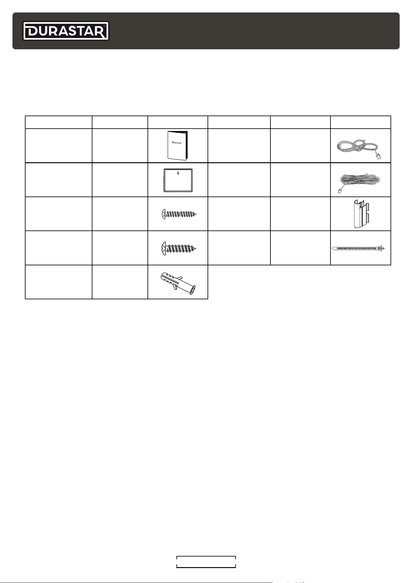
ACCESSORY QUANTITY IMAGE ACCESSORY QUANTITY IMAGE
Manual 2
Room Temp.
Sensor T1
1
Coil
Interface
(PDRUCINT1)
1
Room Temp.
Sensor
Extension (5m)
1
Coil Interface
Screws M4*35
3
Coil Sensor
Clamp
1
Coil Interface
Screws 5/8"
M4*16
4 Cable Ties 1
Coil Interface
Anchors
3
INCLUDED INSTALLATION ACCESSORIES
The coil comes with the following accessories. These are usually packaged in the air outlet.
Remove before install.
ACCESSORIES
R
DURASTAR.COM
17
OPERATING TEMPERATURES
Your coil is designed to operate in the following indoor and outdoor temperatures. When your coil is
used outside of the following temperature ranges, certain safety features may activate and turn off
the unit to protect it from damage.
TEMPERATURE RANGES
COOL mode HEAT mode DRY mode
Indoor Air
Temperature
60°F - 90°F
(16°C - 32°C)
32°F - 86°F
(0°C - 30°C)
50°F - 90°F
(10°C - 32°C)
Outdoor Air
Temperature
-13°F / -22°F* - 122°F
(-25°C / -30°C* - 50°C)
-13°F / -22°F* - 75°F
(-25°C / -30°C* - 24°C)
32°F - 122°F
(0°C - 50°C)
* The minimum operating temperature depends on the outdoor unit. Low ambient Sirius
Heat
TM
models have a minimum operating temperature in heat mode of -22°F (-30°C).
NOTE
Your Durastar heat pump's outdoor unit is equipped with a base pan heater, allowing it
to continue to operate at freezing temperatures as low as -22°F (-30°C). When outdoor
air temperatures are at or below 32°F (0°C), we strongly recommend keeping the unit
plugged in at all times to ensure smooth, ongoing performance.
To further optimize the performance of your unit, do the following:
• Keep doors and windows closed.
• Limit energy usage by using TIMER ON and TIMER OFF features.
• Do not block air inlets or outlets.
• Regularly inspect and clean air lters.
R
DURASTAR.COM18
CARE AND MAINTENANCE
CLEANING THE INDOOR UNIT
• Do not use chemicals or chemically treated cloths to clean the unit.
• Do not use benzene, paint thinner, polishing powder or other solvents to clean the unit. They can
cause the plastic surface to crack or deform. Use of volatile cleaners may cause re, resulting in
injury or death.
• Do not use water hotter than 104°F (40°C) to clean the front panel. This can cause the panel to
deform or become discolored.
• Do not use water to clean the inside of the indoor unit. This can destroy insulation and cause
electrical shock.
WARNING
• Always turn off the unit and disconnect power before cleaning or maintenance.
• Contact an authorized service technician for repair or maintenance. Improper repair
and maintenance may cause water leakage, electrical shock, or re, and may void
your warranty.
• Only use a soft, dry cloth to wipe the unit clean. If the unit is especially dirty, you can
use a cloth soaked in warm water to wipe it clean.
MAINTENANCE: LONG PERIODS OF NON-USE
If you do not plan to use your air conditioner for an extended period of time, do the following:
• Clean all lters.
• Turn on the FAN until the unit dries out completely.
• Turn off the unit and disconnect the power.
• Remove batteries from remote control.
MAINTENANCE: PRE-SEASON INSPECTION
After long periods of non-use, or before periods of frequent use, do the following:
• Inspect for damaged wires.
• Clean all lters.
• Check for leaks.
• Make sure nothing is blocking any air inlets or outlets.
NOTE
It is proper practice to have a trained HVAC technician do a full system check once a year
to promote the longevity of your system.
R
DURASTAR.COM
19
TROUBLESHOOTING
SAFETY PRECAUTIONS
If ANY of the following conditions occur, turn off your unit immediately!
• The power cord is damaged or abnormally warm
• You smell a burning odor
• The unit emits loud or abnormal sounds
• A power fuse blows or the circuit breaker frequently trips
• Water or other objects fall into or out of the unit
DO NOT ATTEMPT TO FIX THESE YOURSELF! CONTACT AN AUTHORIZED SERVICE
PROVIDER IMMEDIATELY!
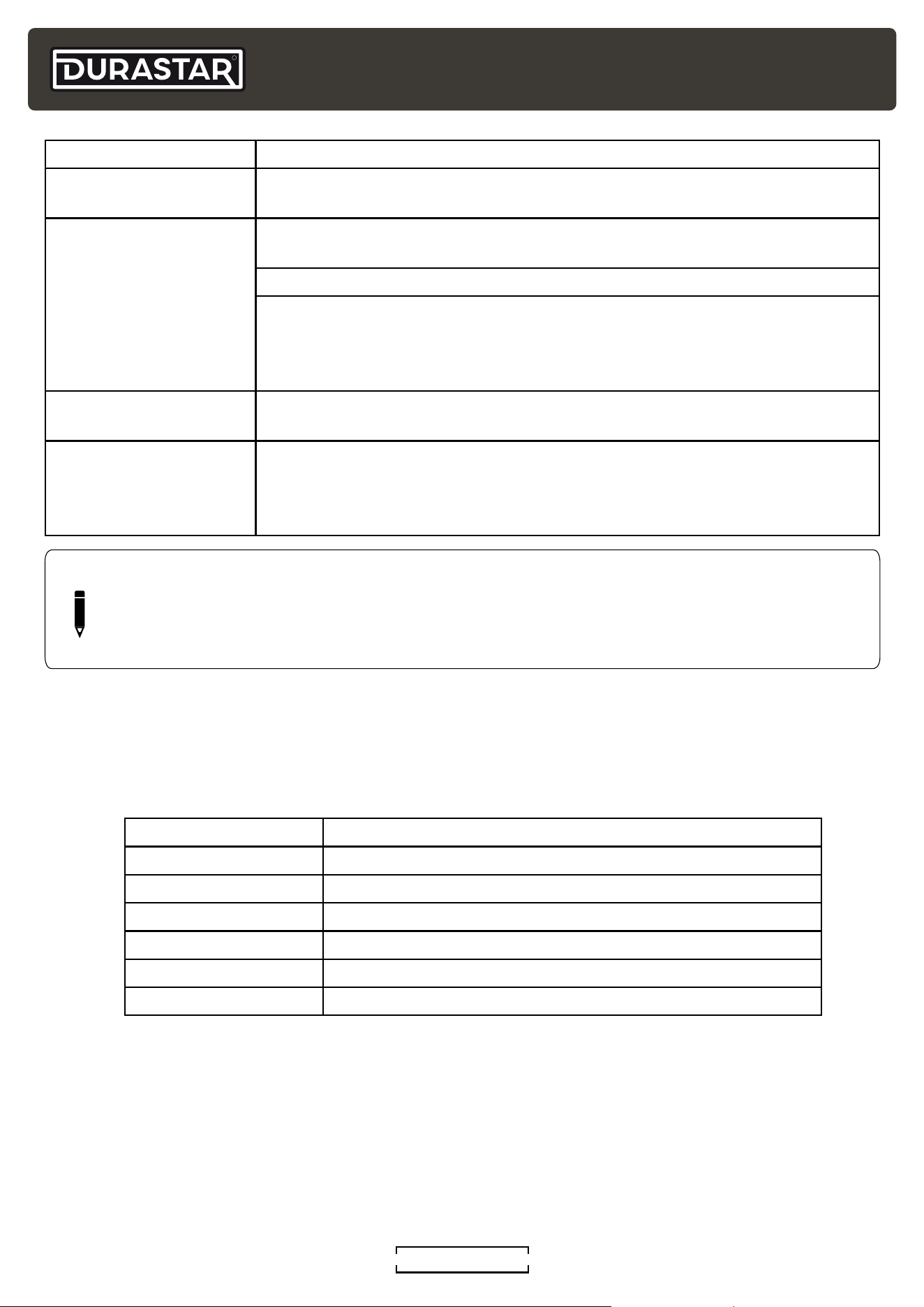
COMMON ISSUES
The following problems are not malfunctions and in most situations do not require repairs.
ISSUE POSSIBLE CAUSES
The unit changes from
COOL/HEAT mode to
FAN mode
The unit may change its setting to prevent frost from forming on the
unit. Once the temperature increases, the unit will start operating in the
previously selected mode again.
The set temperature has been reached, at which point the unit turns off
the compressor. The unit will continue operating when the temperature
uctuates again.
Unit does not turn on
when pressing ON/OFF
button
The unit has a 3-minute protection feature that prevents the unit from
overloading. The unit cannot be restarted within three minutes of being
turned off.
Cooling and Heating Models: If the Operation light and PRE-DEF (Pre-
heating/Defrost) indicators are lit up, the outdoor temperature is too
cold and the unit’s anti-cold wind is activated in order to defrost the unit.
In Cooling-only Models: If the “Fan Only” indicator is lit up, the outdoor
temperature is too cold and the unit’s anti-freeze protection is activated
in order to defrost the unit.
Outdoor units emit
white mist
When the unit restarts in HEAT mode after defrosting, white mist may be
emitted due to moisture generated during the defrosting process.
Both the indoor unit
and outdoor unit make
noises
Low hissing sound during operation: This is normal and is caused by
refrigerant gas owing through both indoor and outdoor units.
Low hissing sound when the system starts, has just stopped running, or
is defrosting: This noise is normal and is caused by the refrigerant gas
stopping or changing direction.
Squeaking sound: Normal expansion and contraction of plastic and
metal parts caused by temperature changes during operation can cause
squeaking noises.
R
DURASTAR.COM20
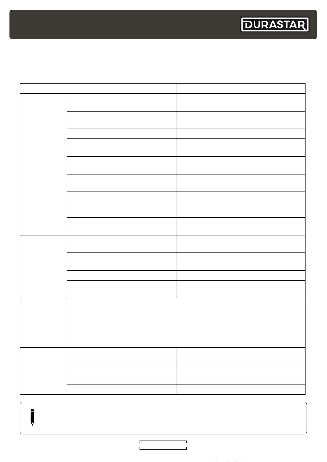
ISSUE POSSIBLE CAUSES
The outdoor unit
makes noises
The unit will make different sounds based on its current operating mode.
The unit emits a bad
odor
The unit may absorb odors from the environment (such as furniture,
cooking, cigarettes, etc.) which will be emitted during operations.
The unit’s lters have become dirty and should be cleaned.
During heating the unit may emit a bad odor. This is a result of the electric
heat module (AUX) heating up and burning off small particles of dust from
the cooling season. This smell will lessen after a few uses and go away
when the AUX heat is off.
The fan of the outdoor
unit does not operate
During operation, the fan speed is controlled to optimize product
operation.
Operation is erratic,
unpredictable, or unit
is unresponsive
In rare cases, interference from radio waves and remote boosters may
cause the unit to malfunction. In this case, try the following:
• Disconnect the power, then reconnect.
• Press ON/OFF button on remote control to restart operation.
NOTE
If problem persists, contact a local dealer or your nearest customer service center. Provide
them with a detailed description of the unit malfunction as well as your model number.
REFRIGERANT LEAK DETECTION (EC)
The indoor unit will automatically display one of the error codes below if it detects a refrigerant
leak. In this case, do not be alarmed, the furnace will go into high fan mode to mitigate refrigerant
collection. If a leak is detected, do not try and service the unit yourself. Contact your dealer or
certied technician for service as soon as possible.
CODE DISPLAYED OPERATION OR ERROR DESCRIPTION
EC C1 Other IDU refrigerant sensor detects leakage (Multi-zone)
EH C1 Refrigerant sensor detects leakage
EH C2 Refrigerant sensor is out of range and leakage is detected
EH C3 Refrigerant sensor is out of range
EL 0C System lacks refrigerant
FH CC Refrigerant sensor error
R
DURASTAR.COM
21
TROUBLESHOOTING
If trouble occurs, please check the following points before contacting a repair company.
PROBLEM POSSIBLE CAUSES SOLUTION
Poor cooling
performance
Temperature setting may be higher
than ambient room temperature.
Lower the temperature setting.
The heat exchanger coil on the
indoor or outdoor unit is dirty.
Contact a servicer to clean the affected
heat exchanger coil.
The air lter is dirty. Replace the air lter.
The air inlet or outlet of either unit is
blocked.
Turn the unit off, remove the obstruction
and turn it back on.
Doors and windows are open. Make sure that all doors and windows are
closed while operating the unit.
Excessive heat is generated by
sunlight.
Close windows and curtains during
periods of high heat or bright sunshine.
Too many sources of heat in
the room (people, computers,
electronics, etc.).
Reduce amount of heat sources.
Return grille is blocked or diffuser
vents are shut.
Make sure the return grille and diffusers
are unrestricted.
Poor heating
performance
The outdoor temperature is
extremely low.
Use auxiliary heating device.
Cold air is entering through doors
and windows.
Make sure that all doors and windows are
closed during use.
The air lter is dirty. Replace the air lter.
Return grille is blocked or diffuser
vents are shut.
Make sure the return grille and diffusers
are unrestricted.
Indicator
lamps
continue
ashing or
error code
appears
The unit may stop operation or continue to run safely. If the indicator lamps
continue to ash or error codes appear, wait for about 10 minutes. The problem
may resolve itself.
If not, turn off the unit, then turn it on again.
If the problem persists, contact your nearest certied service technician.
The unit is not
working
Power failure Wait for the power to be restored
Remote control batteries are dead Replace the batteries
The unit’s 3-minute protection has
been activated
Wait three minutes after restarting the
unit
Timer is activated Turn timer off
NOTE
If your problem persists after performing the checks and diagnostics above, or an error
code remains, turn off your unit immediately and contact an authorized service center.
R
DURASTAR.COM22
LIMITED WARRANTY - PARTS
This Limited Warranty applies to Covered Equipment manufactured on or after November 1
st
, 2024.
COVERED EQUIPMENT is dened by the following model number categories: DRA1_S2A, DRA3_M2A,
DRA4_M2A, DRA5_M2A, DRA6_M2A, DRU1_S2A, DRE1_S2A, DREW_S2AL, DRAC_F2A, DRAD_F2A,
DRAF_F2A, DRAL_F2A, DRAM_F2A, DRAS_F2A, DRAW_F2A, DRUM_S2A, DRUF_S2A, DRUC_S2A
Durastar accessories installed with Covered Equipment carry the balance of the Covered Equipment warranty.
BASE RESIDENTIAL WARRANTY: SEVEN (7) YEARS PARTS
Subject to the terms of this Limited Warranty, Manufacturer will repair or replace, at its option, any part of the
Covered Equipment that is found to be defective in material or workmanship.
Covered Equipment Parts are warranted to be free from defects in material and workmanship for a period of
seven (7) years from the date of installation, under normal use and service. Durastar will, at its option, repair or
replace any part determined by Durastar to be defective. Replacement parts carry the balance of the original
parts warranty. If an exact replacement part is not available, an equivalent part or credit will be provided.
To qualify:
• The Covered Equipment must be installed in a residential single-family home.*
• The Covered Equipment must be properly installed by a licensed HVAC professional pursuant to all local
and state laws.
• Any part to be replaced must be made available to Durastar in exchange for the replacement.
*Single-family home is dened as any single-family dwelling, which includes apartments, condominiums,
duplexes, and homes.
BASE COMMERCIAL WARRANTY: TWO (2) YEAR PARTS
Subject to the terms of this Limited Warranty, Covered Equipment installed in commercial applications are
warranted against defects in material and workmanship for a period of TWO (2) YEARS.
REGISTERED WARRANTY
Parts for Covered Equipment that is registered by the purchaser online within ninety (90) days of the original
installation date shall be warranted for an extended period subject to the terms in this Limited Warranty. Any
Covered Equipment not properly registered within the ninety (90) day registration window will be subject to the
base warranty terms outlined herein. To register your Covered Equipment online, go to: www.durastar.com/
warranty-registration
Registered Residential Warranty: TEN (10) years
Registered Commercial Warranty: FIVE (5) years
FLORIDA, TEXAS, AND CALIFORNIA RESIDENTS ONLY: Failure to register Covered Equipment does not
diminish or decrease your limited warranty length. Covered Equipment will receive the full REGISTERED
WARRANTY terms.
EFFECTIVE DATE OF WARRANTY
The Effective Date of warranty coverage is determined as follows: (a) If the original installation date can
be veried by the installer’s invoice then the Effective Date of warranty coverage is the original installation
date as shown on the installer’s invoice. For residential new construction installations, the nal occupancy
permit, or proof of purchase from the builder can be substituted for the installer’s invoice. (b) if the original
installation date cannot be veried by the installer’s invoice, or proof of purchase from the builder in residential
new construction applications, then the Effective Date of warranty coverage is the Covered Equipment’s
manufacture date (as veried by the product’s serial number) plus ninety (90) days.
LIMITATIONS
There is NO LABOR component provided with this warranty. This Limited Warranty does NOT cover any labor
costs or expenses for service, NOR for removing or reinstalling parts.
R
DURASTAR.COM
23
This Limited Warranty does NOT cover shipping costs for warranty replacement parts from our factory to
the Manufacturer’s distributor or from the distributor to the location of your Covered Equipment. You also are
responsible for the cost of shipping allegedly defective parts to the distributor and for incidental costs incurred
locally, including handling charges. (If in Alaska, Hawaii or Canada, you also must pay the shipping costs of
returning the failed part to the port of entry into the continental United States.)
Manufacturer's Liability hereunder is limited to the repair or replacement of Covered Equipment Parts, and
in no event shall exceed the value of the original Covered Equipment Purchase Price. Liability for incidental,
consequential or special damages are specically excluded.
EXCLUSIONS
In addition to the other exclusions identied in this Limited Warranty, this Limited Warranty excludes:
• Damages, malfunctions, or failures resulting from failure to properly install, operate, or maintain Covered
Equipment in accordance with the Manufacturer’s instructions.
• Damages, malfunctions, or failures resulting from misuse, accident, contaminated, or corrosive
atmosphere, vandalism, freight damage, re, ood, freeze, lightning, acts of war, acts of God and the like.
• Non-original parts installed with Covered Equipment or used in connection with normal maintenance, such
as cleaning or replacing air lters, refrigerant, thermostats, tubing, or concrete pads.
• Covered Equipment that is not installed in the United States.
• Covered Equipment that is not installed by a qualied, trained or licensed HVAC professional in accordance
with applicable codes, ordinances, and good trade practices.
• Damages, malfunctions, or failures resulting from the use of any attachment, accessory, or component not
authorized by the Manufacturer or resulting from alteration or modication of the unit.
• Covered Equipment moved from the original installation location.
• Covered Equipment when operated with system components (indoor unit, outdoor unit, coil, and
refrigerant control devices) or accessories which do not match or meet the specications recommended
by the Manufacturer.
• Any Covered Equipment manufactured that has been sold to the consumer via the Internet or auction
website, and has not been installed by a trained, qualied HVAC professional.
• Covered Equipment that is not part of a properly matched system as specied by the Air Conditioning,
Heating & Refrigeration Institute (AHRI).
OBTAINING WARRANTY SERVICE
If you believe your Covered Equipment is defective, contact the licensed contractor who installed your mini-
split system. Alternatively, contact a licensed contractor, dealer, or distributor.
Durastar Customer Support is available for troubleshooting assistance. Before contacting Customer Support,
please locate your model number, serial number, and proof of purchase. These items will be required to
complete any warranty service. A Durastar authorized representative will verify warranty eligibility and
determine appropriate service options. Service will be provided during normal business hours.
The warranty claim must be submitted at www.durastar.com/warranty-claim by the servicing contractor within
90 DAYS after the date of service in order for the warranty to be approved. The service invoice and/or return
of parts may be requested to verify eligibility.
THIS WARRANTY IS IN LIEU OF ANY OTHER WARRANTY, EXPRESS OR IMPLIED, INCLUDING WITHOUT
LIMITATION, ANY WARRANTY OF MERCHANTABILITY OR FITNESS FOR A PARTICULAR PURPOSE. TO THE
EXTENT ANY IMPLIED WARRANTY IS REQUIRED BY LAW, IT IS LIMITED IN DURATION TO THE EXPRESS
WARRANTY PERIOD ABOVE. NEITHER THE MANUFACTURER NOR ITS DISTRIBUTORS SHALL BE LIABLE
FOR ANY INCIDENTAL, CONSEQUENTIAL, INDIRECT, SPECIAL, OR PUNITIVE DAMAGES OF ANY NATURE,
INCLUDING WITHOUT LIMITATION, LOST REVENUES OR PROFITS, OR ANY OTHER DAMAGE WHETHER
BASED IN CONTRACT, TORT, OR OTHERWISE. IN NO EVENT AND UNDER NO CIRCUMSTANCE OF ANY TYPE
OR KIND SHALL THE SELLER, MANUFACTURER AND/OR DISTRIBUTOR BE LIABLE FOR ANY REASON,
UNDER ANY THEORY, FOR MORE THAN THE BASIC COST OF THE PRODUCT TO THE PURCHASER OR END
USER. SOME STATES DO NOT ALLOW THE EXCLUSION OF INCIDENTAL OR CONSEQUENTIAL DAMAGES,
SO THE ABOVE EXCLUSION MAY NOT APPLY TO YOU. THIS WARRANTY GIVES YOU SPECIFIC LEGAL
RIGHTS. YOU MAY HAVE OTHER RIGHTS THAT VARY FROM STATE TO STATE.
R
DURASTAR.COM24
THIS PAGE INTENTIONALLY LEFT BLANK.
©2026 Durastar
V1.0 0126