User Guide
Quality, Design and Innovation
home.liebherr.com/fridge-manuals
Contents
1 General safety instructions.................................. 2
2 The appliance at a glance..................................... 4
2.1 Included in delivery...................................................... 4
2.2 Overview of appliances and equipment................... 4
2.3 Special features........................................................... 4
2.4 Range of appliance use............................................... 4
2.5 Sound emission of the appliance.............................. 5
2.6 Conformity..................................................................... 5
2.7 SVHC substances according to REACH regulation. 5
3 Setting up and connecting.................................... 5
3.1 Installation conditions................................................ 5
3.2 Appliance dimensions................................................. 6
3.3 Transporting the appliance........................................ 6
3.4 Unpacking the appliance............................................ 6
3.5 Door hinge change....................................................... 6
3.6 Aligning the door.......................................................... 9
3.7 Setting up the appliance............................................ 9
3.8 Setting up multiple appliances.................................. 10
3.9 Pushing the appliance under a countertop............. 10
3.10 After setup.................................................................... 10
3.11 Disposal of packaging................................................. 10
3.12 Connecting the appliance to the power supply...... 10
4 Functionality of the display.................................. 11
4.1 Navigation using touch button and symbol
explanation................................................................... 11
4.2 Menus............................................................................. 11
5 Start-up................................................................. 13
5.1 Switching on the appliance (first use)..................... 13
6 Storage.................................................................. 13
6.1 Information regarding storing items......................... 13
7 Use......................................................................... 13
7.1 Operating and display elements................................ 13
7.1.1 Temperature display/status display......................13
7.1.2 LED behavior..............................................................14
7.1.3 Acoustic signals........................................................ 14
7.2 Appliance functions..................................................... 14
7.2.1 Notes on the appliance functions..........................14
Switching appliance off and on.............................14
Temperature..............................................................15
7.2.4 WLAN/LAN................................................................. 15
Demo mode............................................................... 16
Resetting to factory settings................................. 17
7.3 Messages...................................................................... 17
7.3.1 Ending messages...................................................... 17
8 Equipment............................................................. 18
8.1 Safety lock.................................................................... 18
8.2 Sensors.......................................................................... 18
9 Maintenance.......................................................... 18
9.1 Maintenance schedule................................................ 18
9.2 Defrosting the appliance............................................ 19
9.3 Cleaning the appliance............................................... 19
10 Customer support................................................. 20
10.1 Technical data.............................................................. 20
10.2 Technical malfunction................................................. 21
10.3 Customer Service......................................................... 21
10.4 Type plate...................................................................... 21
11 Shutting down....................................................... 21
12 Disposal................................................................. 22
12.1 Preparing appliance for disposal.............................. 22
12.2 Disposing of the appliance in an environmentally
friendly manner............................................................ 22
13 Additional information.......................................... 22
The manufacturer is constantly working to improve all types
and models. Therefore, please be aware that we reserve the
right to make changes to the shape, equipment and tech‐
nology.
Symbol Explanation
Read instructions
Please read the information in these instruc‐
tions carefully to understand all of the benefits
of your new appliance.
Additional information online
The digital manual with supplemental informa‐
tion and in additional languages can be found
online by scanning the QR code on the front
page of this manual or by entering the service
number at home.liebherr.com/fridge-
manuals.
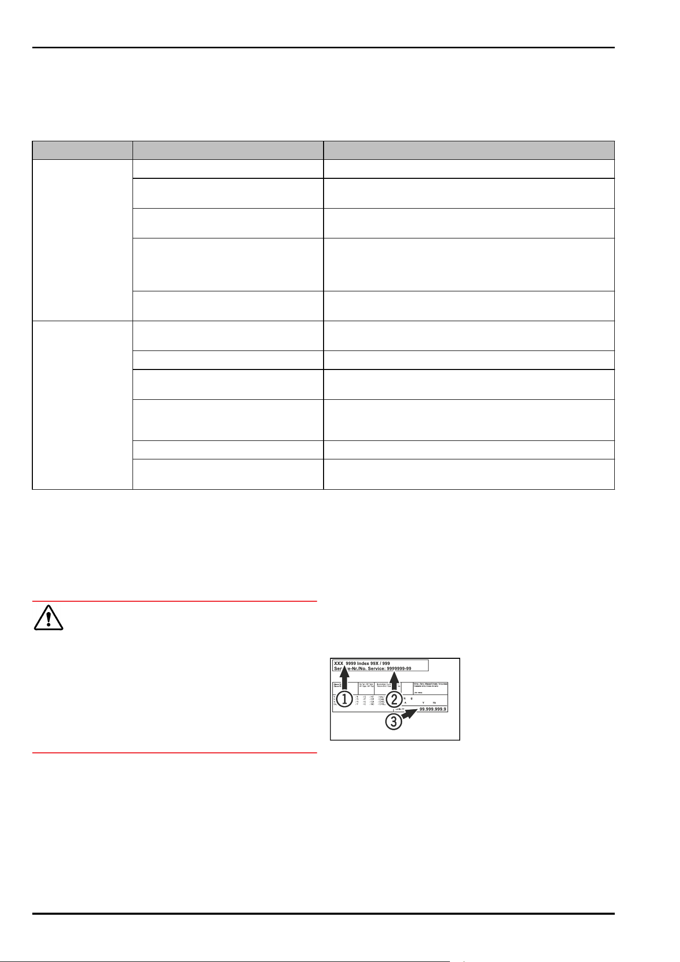
The service number can be found on the serial
tag:
Fig.Example illustration
Check appliance
Check all parts for transport damage. If you
have any complaints, please contact your
agent or customer service.
Differences
These instructions apply to a range of models,
so there may be differences. Sections that
apply to certain models only are indicated by
an asterisk (*).
Instructions and results
Instructions are marked with a .
Results are marked with a .
Videos
Videos about the appliances are available on
the YouTube channel of Liebherr-Hausgeräte.
Open-source licenses:
The appliance includes software components that make
use of open-source licenses. You can find information on
the open-source licenses to be used here:
home.liebherr.com/open-source-licenses
These operating instructions apply to:
SRC..
801
1 General safety instructions
Please keep these operating instructions in a safe place so
you can refer back to them at any time.
If you pass the appliance on, please hand these operating
instructions to the new owner.
General safety instructions
2 * Depending on model and options
Read these operating instructions before use in order to use
the appliance safely and correctly. Follow the instructions,
safety instructions and warning messages included at all
times. They are important for ensuring you can operate and
install the appliance safely and without any problems.
Dangers for the user:
-
This appliance may only be used by specialist and labora‐
tory personnel who have been trained for this purpose
and are familiar with all the safety measures for work in a
laboratory. Children and persons with impaired physical,
sensory or mental abilities or with a lack of experience
and knowledge may not commission or operate this
appliance.
-
The socket must be easily accessible so that the appli‐
ance can be disconnected quickly from the electricity in
an emergency. It must not be located in the area behind
the appliance.
-
Always hold the plug of the cable when disconnecting
the appliance from the power supply. Do not pull on the
cable.
-
Remove the plug or disconnect via the fuse if there is a
malfunction.
-
WARNING: Do not damage the power cable. Do not
operate the appliance with a faulty power cable.
-
WARNING: Multi-sockets/power distributors and other
electronic appliances (such as halogen transformers)
may not be placed and operated behind appliances.
-
WARNING: Do not block the ventilation openings in the
appliance housing or in the installation housing.
-
Repairs and work on the appliance may only be carried
out by Customer Service or other specifically trained
qualified personnel.
-
Always follow the instructions when assembling,
connecting and disposing of the appliance.
Risk of fire:
-
The refrigerant contained within the appliance (specifica‐
tions on the type plate) is environmentally friendly, but
flammable. Leaking refrigerant can ignite.
•
WARNING: Do not damage the refrigerant circuit.
•
Do not handle ignition sources inside the appliance.
•
WARNING: Do not use electrical appliances inside the
food storage compartments of the appliance, unless
they are of the type recommended by the manufac‐
turer.
•
If refrigerant leaks: Remove naked flames or ignition
sources located near the area of the leak. Ventilate the
room well. Contact Customer Service.
-
Do not operate the appliance near explosive gases.
-
Do not store or use gasoline or other flammable gases
and liquids near the appliance.
-
Do not store explosive substances such as aerosol cans
with a flammable propellant in this appliance. You can
recognize such spray cans by the printed list of contents
or by a flame symbol. Any leaking gases can be ignited by
electrical components.
-
Keep lit candles, lamps and other objects with naked
flames away from the appliance so they do not cause a
fire.
-
Alcoholic liquids or other containers holding alcohol must
always be tightly sealed for storage purposes. Any
leaking alcohol can be ignited by electrical components.
Risk of falling or toppling over:
-
Do not stand on the base, drawers, doors etc. or use
them as improper supports.
Danger of frostbite, feeling of numbness and pain:
-
Avoid prolonged skin contact with cold surfaces or
chilled/frozen food or take protective measures, e.g.
wear gloves.
Risk of injury and damage:
-
WARNING: Do not use mechanical devices or other
means to accelerate the defrosting process, other than
those recommended by the manufacturer.
-
WARNING: Risk of injury due to electric shock! There are
live electrical parts under the cover.
Have the LED interior lighting replaced or repaired only by
Customer Service or other suitably trained professionals.
-
NOTICE: The appliance must only be operated using orig‐
inal manufacturer accessories or accessories from other
providers approved by the manufacturer. The user bears
the risk of using accessories which are not approved.
Risk of crushing:
-
Do not reach into the hinge when opening and closing the
door. Fingers may get trapped.
Specialist personnel qualifications:
The appliance may only be installed, tested, maintained,
and commissioned by specialist personnel who are
familiar with the installation, commissioning, and opera‐
tion of the appliance.
Specialist personnel are persons who, on account of their
specialist training, knowledge and experience as well as
their knowledge of the relevant standards, are able to
assess and perform the work assigned to them and iden‐
tify potential hazards. They must have training, instruc‐
tion, and authorization to work on the appliance.
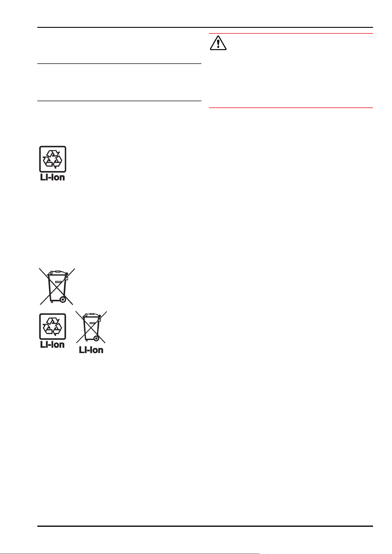
Symbols on the device:
The symbol may be located on the
compressor. It refers to the oil in the
compressor and refers to the following
danger: Can be fatal if swallowed or
inhaled. This notice only applies for recy‐
cling. There is no danger during normal
operation.
WARNING: Risk of fire / flammable mate‐
rials. The symbol is located on the
compressor and indicates the danger from
flammable materials. Do not remove the
label.
This label or a similar one may be located
on the rear of the appliance. This label indi‐
cates that there are vacuum insulation
panels (VIP) or perlite panels in the door
and/or housing. This notice only applies for
recycling. Do not remove the label.
Observe the warning messages and other detailed infor‐
mation in the other sections:
DANGER
Indicates an immediately hazardous
situation, which if not avoided, will
result in death or serious injury.
WARNING
Indicates a hazardous situation, which
if not avoided, could result in death or
serious injury.
CAUTION
Indicates a hazardous situation, which
if not avoided, could result in minor or
moderate injury.
NOTICE
Indicates a hazardous situation, which
if not avoided, could result in damage
to property.
Note Indicates useful advice and tips.
General safety instructions
* Depending on model and options 3
2 The appliance at a glance
2.1 Included in delivery
Check all parts for transport damage. If you have any
issues, please contact your dealer or Customer Service.
(see 10.3 Customer Service)
The delivery contains the following parts:
-
Freestanding appliance
-
Equipment *
-
Installation materials *
-
Operating instructions
-
Service brochure
-
Quality certificate *
-
Power cable
2.2 Overview of appliances and equip‐
ment
1
5
4
4
7
7
8
3
6
9
2
Fig. 1 Example illustration
Equipment
(1)
Controls (6) Defrost water drain
(2) C sensor (7) Adjustable foot
(3) Sensor lead-through P
sensor
(8) Lock
(4) Shelf (9) Lighting
(5) Type plate
1
2
Fig. 2 Exemplary illustration of the rear side
Equipment
(1)
Housing with slot for
the SmartModule
(2) LAN interface
2.3 Special features
Note
You can obtain accessories from our customer service
(see 10.3 Customer Service) or from authorized distributors
using the distributor search function on our service page on
the Internet:
home.liebherr.com
SmartModule
You can fit the appliance with a SmartModule.
This is a WLAN and LAN interface for the connection
between the appliance and an external documentation and
alarm system, such as the Liebherr SmartMonitoring dash‐
board, for example.
The Liebherr SmartMonitoring dashboard is not available
in all countries. Check for availability via the QR code
(see 7.2.4WLAN/LAN) and entering your model.
Retrofitting drawers
Temperature qualification is required when retrofitting
drawer systems in Liebherr refrigerators/freezers where
these are used for temperature-sensitive materials
such as chilled drugs and refrigerated products that are
subject to specific standard requirements. Retrofitting
drawers in Liebherr refrigerators/freezers can result in the
goods stored becoming spoiled or damaged. The retrofit‐
ting must therefore be completed exclusively by author‐
ized service providers from the manufacturer of the refrig‐
erator/freezer.
2.4 Range of appliance use
Intended use
This laboratory fridge is suitable for the professional
storage of products at temperatures between 3°C and 7°C.
Typical products to be stored include research samples,
reagents, laboratory inventory etc.
Storage of temperature-sensitive substances requires the
use of an independent, permanently monitored alarm
system. This alarm system must be designed such that a
responsible person can record every alarm condition to be
able to take suitable measures.
Foreseeable incorrect use
Do not use the appliance for the following applications:
-
Storage and cooling of:
•
Chemically unstable, flammable or corrosive
substances
•
Blood, plasma or other body fluids for the purpose of
infusion, application or introduction in the human
body.
-
Use in potentially explosive atmospheres.
-
Use outdoors or in areas exposed to dampness and
splashing water.
-
Used in a residential spaces because suitable protection
of radio reception cannot be ensured in these environ‐
ments.*
Any misuse of the appliance may result in damage to or
spoilage of stored goods.
Climate classes
The climate class for your appliance is printed on the identi‐
fication plate.
The appliance at a glance
4 * Depending on model and options
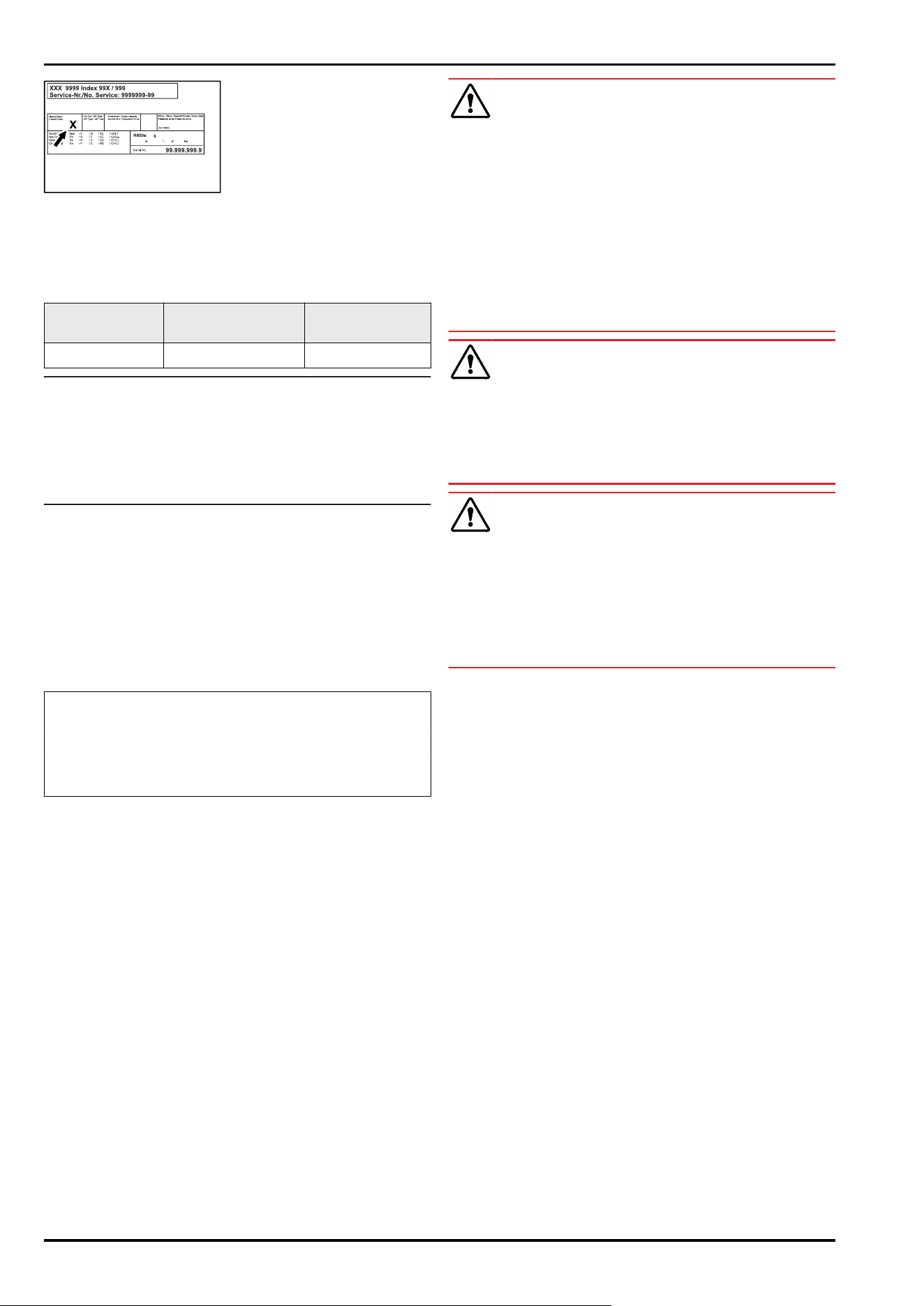
Fig. 3 Type plate
(X) This climate class indi‐
cates the environ‐
mental conditions in
which the appliance
can be operated safely.
Climate class (X) max. room tempera‐
ture
max. rel. humidity
7 35°C 75%
Note
The minimum permitted room temperature at the setup
location is 10°C.
The interior temperature of the appliance never exceeds the
ambient temperature at the setup location.
Slight condensation may form on the glass door on the side
walls if the boundary conditions are exceeded.
2.5 Sound emission of the appliance
The A-weighted emission sound pressure level during oper‐
ation of the appliance is below 70 dB(A) (sound power
rel.1 pW).
2.6 Conformity
The refrigerant circuit has been tested for leaks. The appli‐
ance complies with the relevant safety regulations.
The designated product complies with the provisions of
the following European directives and regulations:
(EU) 2019/2020, 2014/35/EU, 2014/30/EU, 2011/65/EU
The complete text of the EU Declaration of Conformity is
available online at: www.liebherr.de
2.7 SVHC substances according to
REACH regulation
You can check whether your appliance contains SVHC
substances according to REACH regulation at the following
link: home.liebherr.com/de/deu/de/liebherr-erleben/nach‐
haltigkeit/umwelt/scip/scip.html
3 Setting up and connecting
3.1 Installation conditions
The installation conditions are crucial to ensure that you
can operate your appliance safely, efficiently, and trouble-
free.
-
Observe all safety instructions.
-
Observe the installation location and position in the
room.
WARNING
Danger of fire due to incorrect positioning!
If the power supply cable or plug touches the back of the
appliance, the vibration can damage the power supply cable
or the plug resulting in a short circuit.
► Make sure the power supply cable is not trapped under
the appliance when you position the appliance.
► Install the appliance so that it does not touch any plugs
or power cables.
► Do not connect any appliances to sockets in the area of
the back of the appliance.
► Do not place and operate power strips/power distribu‐
tors and other electronic devices (such as halogen trans‐
formers) at the back of the appliances.
WARNING
Risk of fire due to moisture!
If live parts or the power cord get wet, this can cause a
short circuit.
► The appliance is designed for use in enclosed spaces. Do
not operate the appliance in open space or in damp areas
or where there is spray.
WARNING
Leaking refrigerant and oil!
Fire. The refrigerant contained within the appliance is envi‐
ronmentally friendly, but flammable. The oil contained
within the appliance is flammable. Escaping refrigerant and
oil can ignite if they are of high enough concentration and
are exposed to an external heat source.
► Do not damage the pipelines of the coolant circuit and
the compressor.
3.1.1 Installation location
-
The optimum installation location is a dry and well-venti‐
lated space.
-
If the appliance is set up in a very humid environment,
condensation may form on the outside of it.
Always ensure good ventilation at the installation loca‐
tion.
-
The more refrigerant there is in the appliance, the larger
the room in which the appliance is installed must be. If
the room is too small, a flammable gas/air mixture may
form in the event of a leak. Per 8g refrigerant, the instal‐
lation space must be at least 1 m
3
in size. Information on
the refrigerant contained can be found on the type plate
inside the appliance.
-
The floor at the installation location must be horizontal
and level.
-
The installation location must be able to support the
weight of the appliance, including its maximum storage
capacity. (see 10.1 Technical data)
-
Do not install an appliance on to of another one, a coun‐
tertop, a cabinet or similar.
3.1.2 Position in the space
-
Do no set up the appliance in an area with direct sunlight,
next to a heating unit or similar.
-
Always place the rear of the appliance directly against
the wall.
-
Use in potentially explosive atmospheres is not
permitted.
Setting up and connecting
* Depending on model and options 5
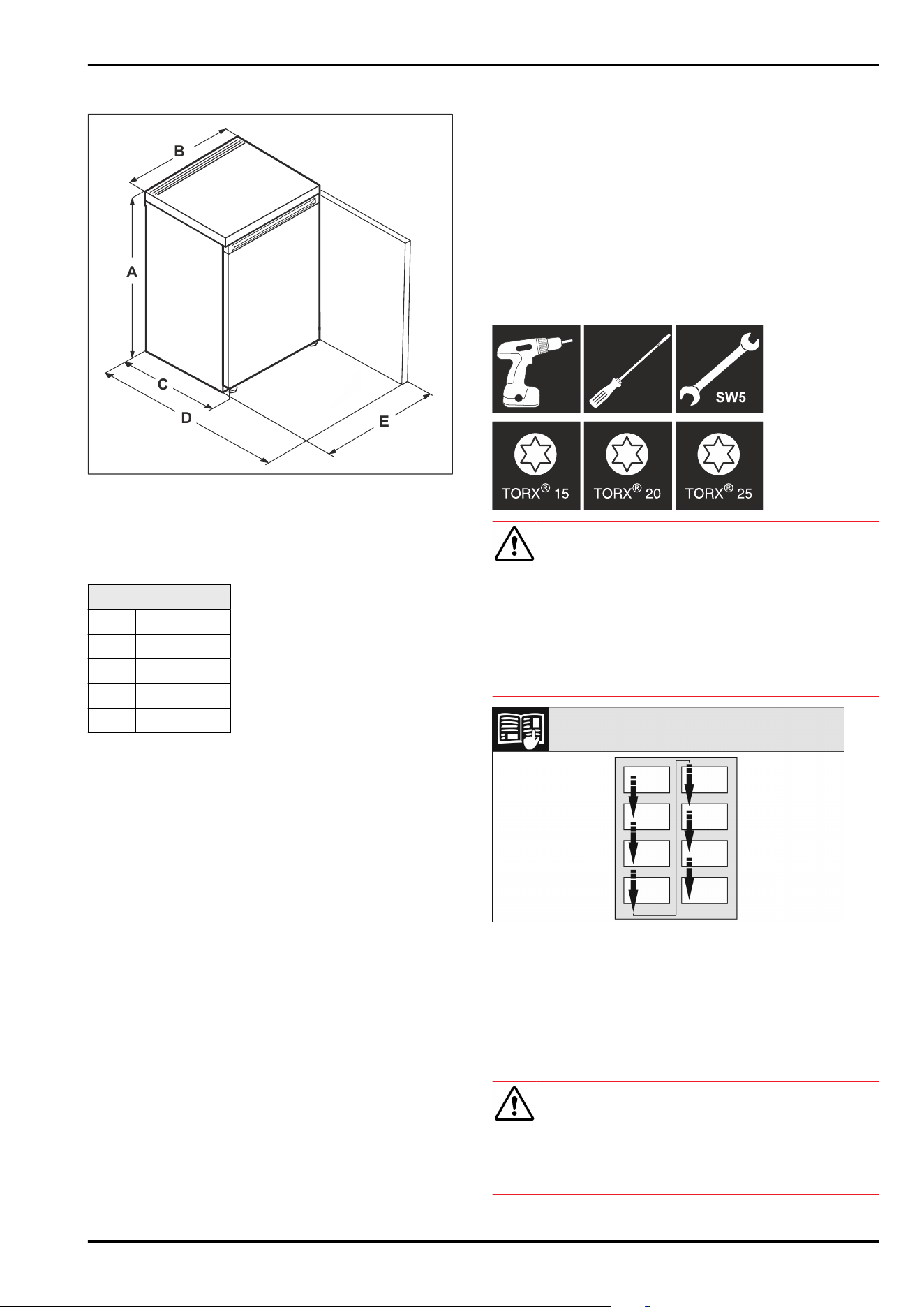
3.2 Appliance dimensions
A
B
C
D
E
Fig. 4 Example illustration
(A)
Appliance height
including feet
(D) Appliance depth with
open door
(B) Appliance width (E) Appliance width with
open door
(C) Appliance depth
SRC.. 801 / SFC..801
A 680mm
B 550mm
C 610mm
D 1106mm
Е 547mm
3.3 Transporting the appliance
3.3.1 Transporting the appliance for initial
installation
Make sure that the following requirements are fulfilled:
❑
Appliance is packaged.
❑
The appliance is upright.
► Have two people transport the appliance.
► Unpack the appliance.
3.3.2 Transporting the appliance after initial
installation
Observer the following instructions if you want to transport
or move the appliance after initial installation.
Make sure that the following requirements are fulfilled:
❑
Appliance is empty.
❑
The appliance is upright.
❑
Appliance with door(s): The door is secured against unde‐
sired opening.
❑
Appliance with pull-out cart: The pull-out cart is secured
against undesired opening.
❑
Appliance with adjustable feet: Adjustable feet are
turned in.
► Have two people transport the appliance.
After transporting it:
►
Align the appliance.
3.4 Unpacking the appliance
► Check the appliance and the packaging for transport
damage. Contact the supplier immediately if you suspect
any damage. Do not connect the appliance to the power
supply.
► Remove all packaging materials from the rear or the side
walls of the fridge that may prevent proper installation or
prevent air flow and ventilation.
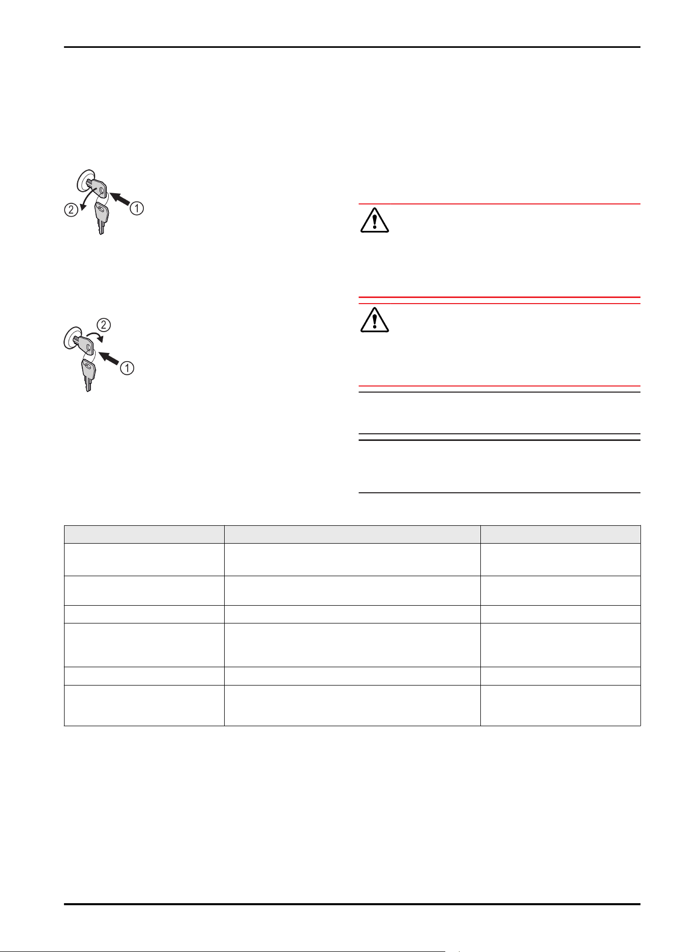
3.5 Door hinge change
Tool
WARNING
Danger of injury due to door falling out!
If the bearing parts are not screwed on tightly enough, the
door may fall out. This can result in serious injuries. In addi‐
tion, the door may not close causing the appliance to cool
improperly.
► Screw on the bearing brackets/bearing pins tightly with
4Nm.
► Check all screws and retighten them if necessary.
Fig.5
Observe the reading direction.
3.5.1 Preparation
► Unlock the appliance.
► Tilt the appliance backwards using two people.
3.5.2 Dismantling the lower bearing parts
CAUTION
Risk of injury from door tipping out!
If you completely remove the pin on the door, the door may
tip out and you may be injured.
► Hold the door before removing the pin.
Setting up and connecting
6 * Depending on model and options
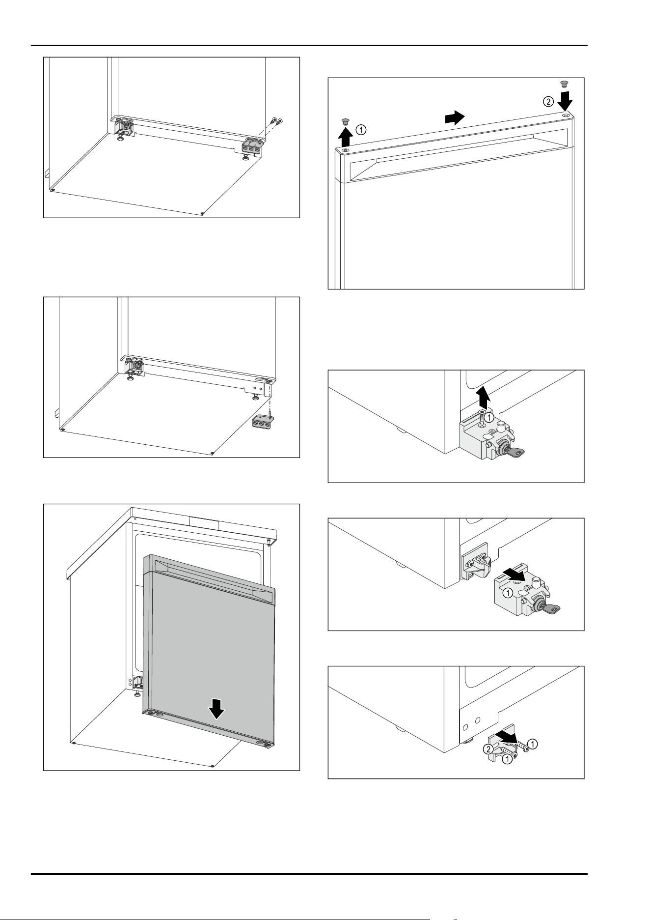
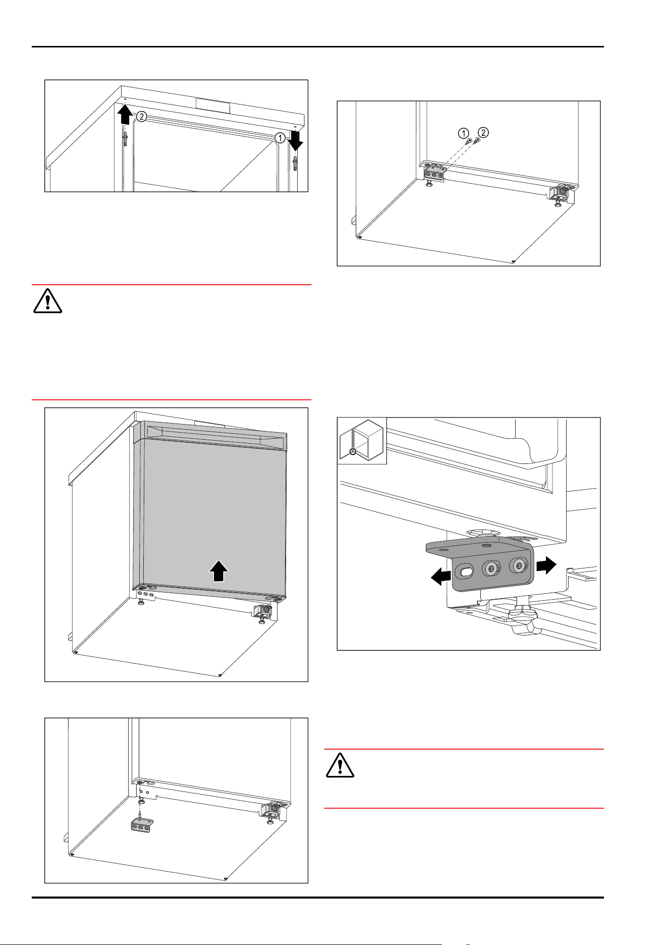
Fig.6
► Unscrew the middle screw on the lower swap bearing
block using a Torx 20 screwdriver. Fig.6()
► Unscrew the inner screw on the lower swap bearing
block using a Torx 20 screwdriver. Fig.6()
► Set the screws aside.
Fig.7
► Remove the swap bearing block downwards. (see Fig.7)
► Set the swap bearing block aside.
Fig.8
► Remove the door downwards. (see Fig.8)
► Set the door down.
3.5.3 Preparing the door
Fig.9
► Carefully lift the cover plug on the top of the door
Fig.9(1) using a slotted screwdriver.
► Insert the cover plug on the opposite side. Fig.9(2)
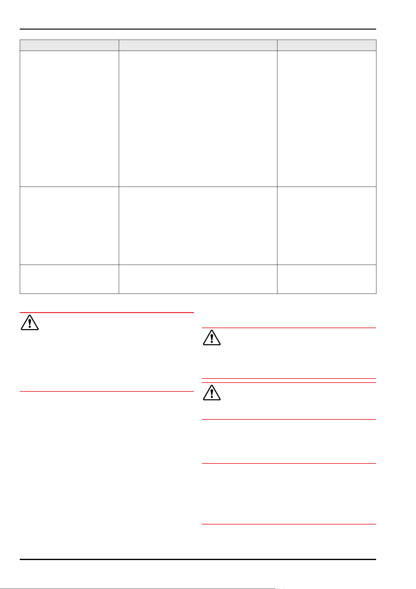
3.5.4 Replacing the lock
Fig. 10
► Unscrew the screw Fig. 10(1).
Fig.11
► Remove the locking device Fig.11(1) from the front.
Fig.12
► Unscrew the screws Fig.12(1).
► Remove the retaining part Fig.12(2) from the front.
Setting up and connecting
* Depending on model and options 7
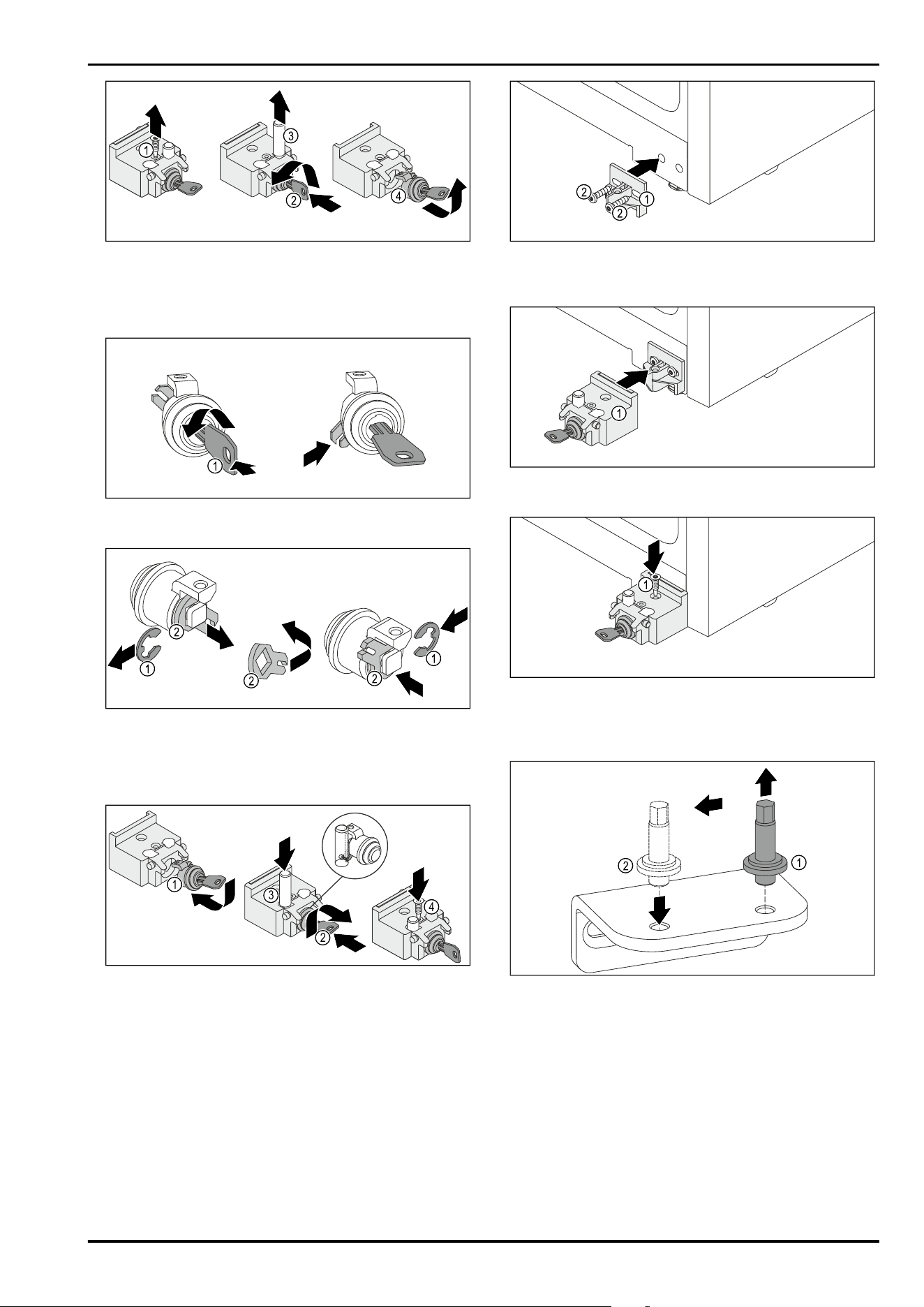
Fig.13
► Unscrew the screw Fig.13(1).
► Press in the key Fig.13(2) and turn it.
► Remove the pin Fig.13(3) upward.
► Pull out the key Fig.13(4).
Fig. 14
► Press in the key Fig. 14(1) and turn it.
Fig. 15
► Remove the retaining ring Fig. 15(1).
► Remove the locking hook Fig. 15 (2), turn it around and
reinsert it.
► Insert the retaining ring Fig. 15(1).
1
4
3
2
Fig. 16
► Insert the lock Fig. 16(1).
► Press in the key Fig. 16(2) and turn it.
► Insert the pin Fig. 16(3).
▷ After it has been inserted, the transverse pin in the bolt
sits in the groove of the lock hook.
► Screw in the screw Fig. 16(4).
Fig.17
► Attach the retaining part Fig. 17 (1) with the screws
Fig.17(2) on the opposite side of the appliance housing.
Fig. 18
► Attach the locking device Fig. 18(1).
Fig. 19
► Screw in the screw Fig. 19(1).
3.5.5 Moving the lower bearing parts
Fig.20
► Unscrew the bolt of the lower swap bearing block using
an SW5 external hexagon wrench. Fig.20(1)
► Insert the bolt on the opposite side. Fig.20(2)
► Tighten the bolt using an SW5 external hexagon wrench.
Setting up and connecting
8 * Depending on model and options
3.5.6 Moving the upper bearing parts
Fig.21
► Unscrew the upper bolt using an external hexagon
wrench. Fig.21(1)
► Tighten the bolt on the opposite side using an external
hexagon wrench. Fig.21(2)
3.5.7 Installing the door
WARNING
Danger of injury due to door falling out!
If the bearing parts are not screwed on tightly enough, the
door may fall out. This can result in serious injuries. In addi‐
tion, the door may not close causing the appliance to cool
improperly.
► Screw the bearing brackets on firmly with 4Nm.
► Check all screws and retighten them if necessary.
Fig.22
► Slide the door onto the upper pin while open. (see Fig.22)
Fig.23
► Insert the lower swap bearing block on the opposite side.
(see Fig.23)
Fig. 24
► Tighten the middle screw of the swap bearing block
Fig. 24(1) using a Torx 20 screwdriver.
► Tighten the inner screw of the swap bearing block
Fig. 24(2) using a Torx 20 screwdriver.
► Check the door.
▷ The door hinge has been changed.
3.6 Aligning the door
If the door is not straight, you can adjust it on the lower
hinge.
Fig.25
► Slightly undo both screws and move the door with the
hinge to the left or right.
► Tighten the screws as far as they will go.
▷ The door is now straight.
3.7 Setting up the appliance
CAUTION
Risk of injury and damage.
► Use 2 people to set up the appliance.
Setting up and connecting
* Depending on model and options 9
CAUTION
Risk of injury and damage.
The door can strike against the wall and become damaged
as a result. In the case of glass doors, the damaged glass
can cause injuries.
► Protect the door from striking against the wall. Attach a
door stopper, e.g. felt stopper, to the wall.
► Connect all necessary components (e.g. power cable) to
the back of the appliance and route to the side.
Note
Cables can be damaged.
► Do not crush the cable when pushing the appliance back.
3.8 Setting up multiple appliances
NOTICE
Risk of damage due to condensation between the side
walls!
► Do not position the appliance directly next to another
cooling device.
► Install appliances with a distance of 10cm between each
appliance.
► When installing multiple appliances next to each other,
ensure that the ambient temperature does not exceed
35°C and the humidity does not exceed 65%.
► Increase the distance between the appliances at higher
humidity levels.
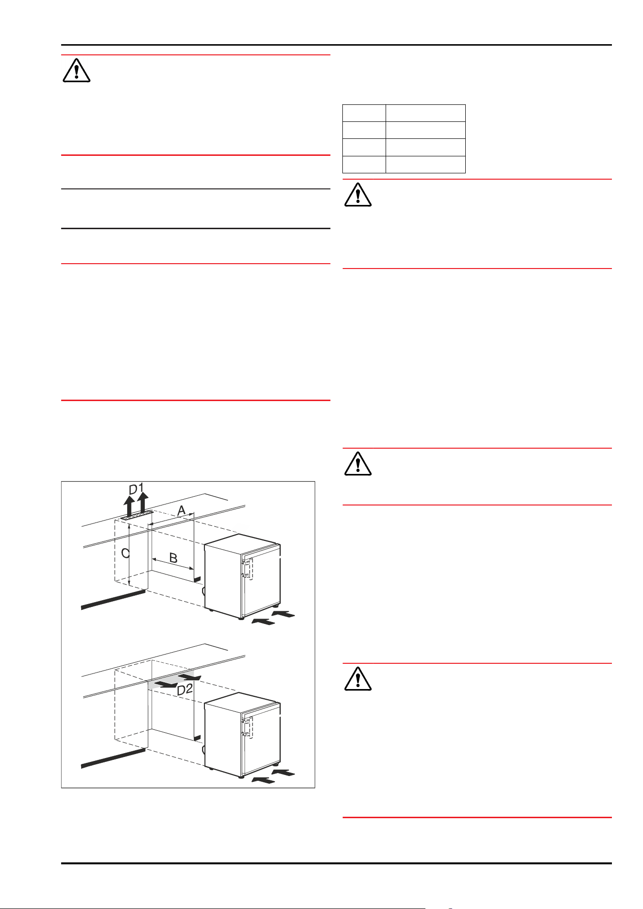
3.9 Pushing the appliance under a coun‐
tertop
You can push table appliances with a maximum appliance
height of 850mm under a continuous countertop.
Fig. 26
(A)
Appliance width
without tabletop
(D1) Ventilation cross-section
in the countertop
(B) Recess depth (D2) Ventilation cross-section
between countertop and
appliance
(C) Recess height
A At least 553mm
B At least 610mm
C At least 685mm
D1 or D2 At least 200cm²
WARNING
Risk of fire from short circuit!
► When setting up the appliance: Do not kink, trap, or
damage the power cable.
► Do not operate the appliance with a defective power
cable.
Make sure that the following requirements are fulfilled:
❑
Outlet is easily accessible and is not behind the appli‐
ance.
► Push the appliance under the countertop.
3.10 After setup
► Peel off the protective films. *
► Clean the appliance. (see 9.3Cleaning the appliance)
► If necessary: Disinfect the appliance.
► Keep the invoice so you have the appliance and dealer
information available if needed.
3.11 Disposal of packaging
WARNING
Danger of suffocation from packaging materials and films!
► Do not allow children to play with packaging materials.
The packaging is made from recyclable materials:
-
Corrugated card/cardboard
-
Parts made of foamed polystyrene
-
Films and bags from polyethylene
-
Packing bands from polypropylene
-
Wood frame nailed together with a polyethylene window*
► Take the packaging material to an official collection
point.
3.12 Connecting the appliance to the
power supply
WARNING
Danger of electric shock and injury due to damaged appli‐
ance or damaged mains cable!
Cuts and fatal injury. If the appliance or the mains cable is
damaged during transport, you may be electrocuted. You
could also cut yourself on damaged parts of the appliance
housing.
► Check the appliance and the mains cable for damage
after transport.
► Never put the appliance into operation if the appliance or
the mains cable are damaged.
► Contact Customer Service.
Setting up and connecting
10 * Depending on model and options
You can connect your appliance to the mains using the
power cable supplied separately. The mains power cable
has an appliance coupler at one end and a mains plug at the
other end.
Make sure that the following requirements are fulfilled:
-
The appliance and power cable are undamaged.
-
The appliance is set up in accordance with the regula‐
tions. (see 3.7 Setting up the appliance)
-
Requirements for the electrical connection are met.
(see 3.1 Installation conditions)
-
Dimensions for connection in accordance with regula‐
tions are known and observed.
-
Mains voltage and frequency correspond to the specifica‐
tions on the type plate.
-
The socket is grounded and fused in accordance with
regulations.
-
The tripping current for the fuse is between 10 A and
16A.
-
Outlet is easily accessible and is not behind the appli‐
ance.
NOTICE
Danger of damage to incorrect operation!
Damage to the electrical components of the appliance.
► Only use the supplied power cable.
WARNING
Danger of fire due to incorrect connection!
Burns.
Damage to the appliance.
► Do not use an extension cord.
► Do not use a multipoint connector strip.
NOTICE
Danger of damage to incorrect connection!
Damage to the appliance.
► Do not connect the appliance to a stand-alone inverter,
e.g. solar power systems and petrol generators.
► Connect the mains plug of the power cord to the power
supply. Ensure the main plug is firmly plugged into the
outlet.
▷ Appliance is connected. For initial commissioning, see
the next chapter or the operating instructions.
4 Functionality of the display
You operate your appliance using the touch button.
4.1 Navigation using touch button and
symbol explanation
In the illustrations, different symbols are used for naviga‐
tion using the touch button. The following table describes
these symbols.
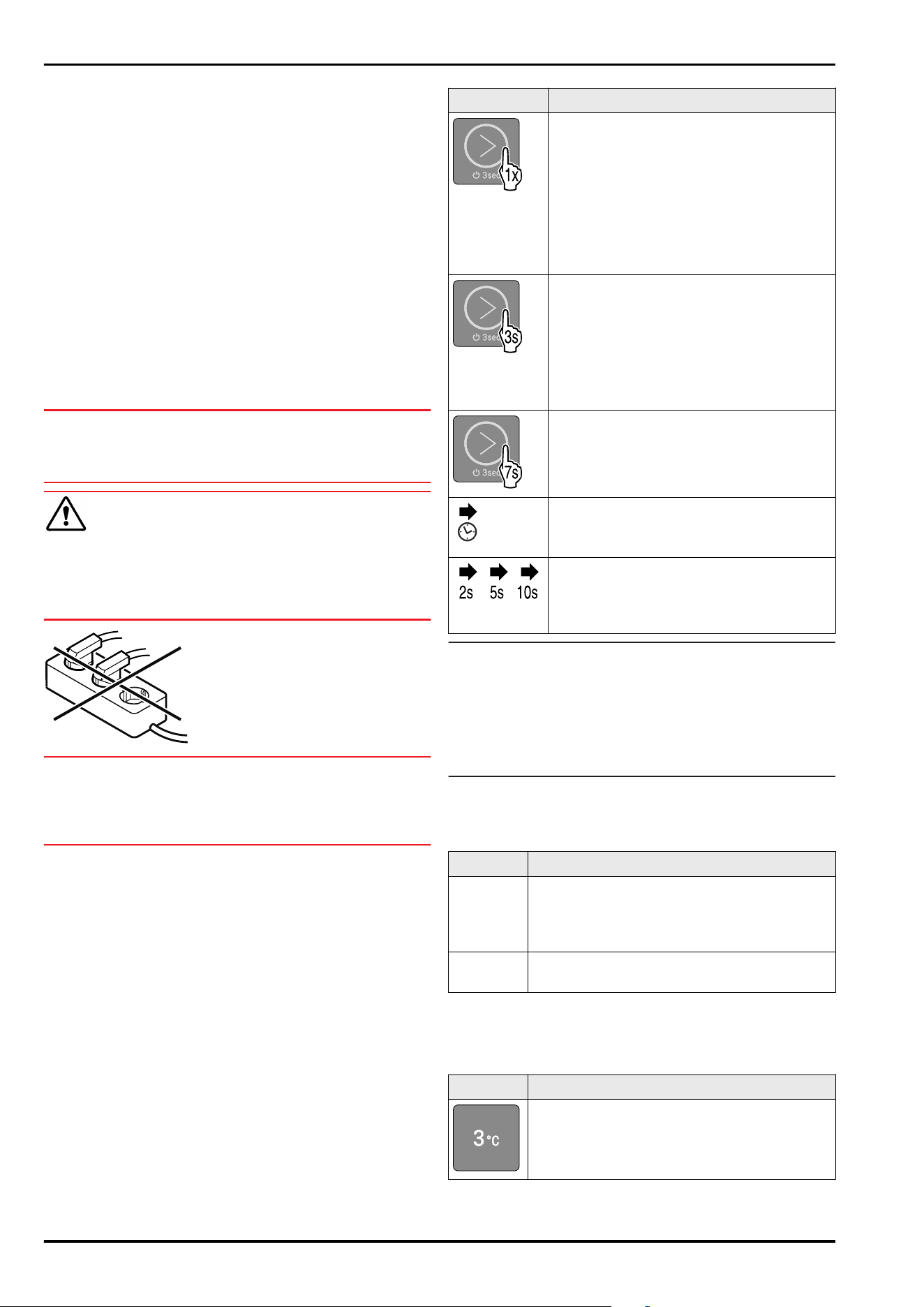
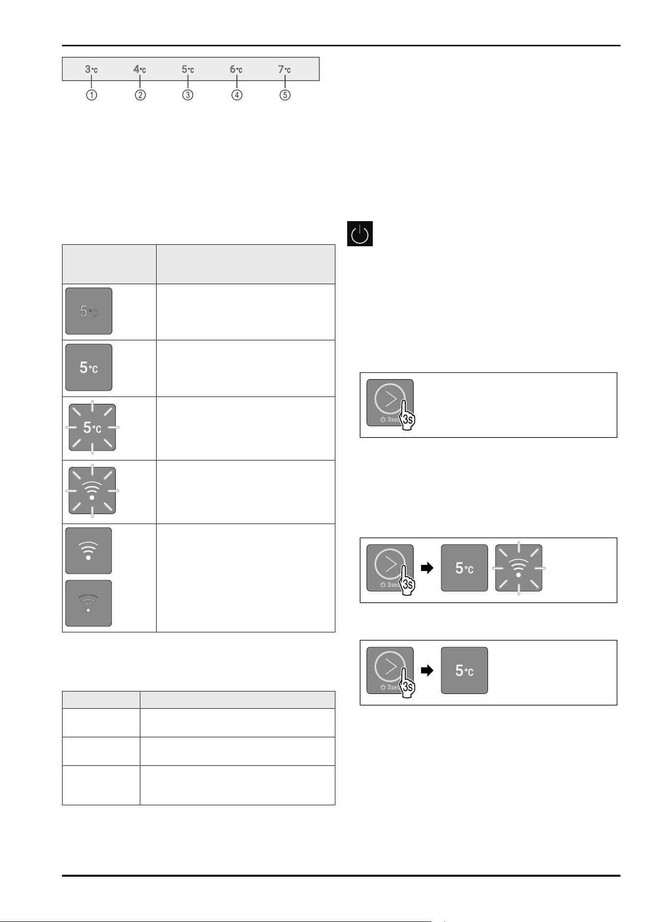
Symbol
Description
Touch the touch button briefly with your
finger:
Navigate through the main menu and
submenu.
If a number is depicted in the hand:
The number tells you how many times you
have to briefly touch the touch button in
succession to navigate to a specific func‐
tion.
Touch the touch button with your finger
for 3seconds:
Switch on appliance.
In the main menu: Switch off appliance.
In the submenu: Switch to the main menu.
Deactivate the active function of the
submenu.
Touch the touch button with your finger
for 7seconds:
In the main menu: Open submenu.
Arrow with clock:
It takes more than 10 seconds for the
following message to appear in the display.
Arrow with a time indication:
It takes the specified amount of time until
the following message appears in the
display.
Note
If you touch the touch button for 15 seconds, the service
menu is opened. The service menu can be recognized by the
flashing of LED 5 and the WLAN LED. This menu is espe‐
cially for service technicians.
► Exit the service menu: Touch the touch button for
3 seconds or perform no action on the display for 5
minutes.
4.2 Menus
The appliance functions can be found in various menus.
Menu
Description
Main menu When you switch the appliance on, you are
automatically in the main menu.
From here you can navigate to the appliance
functions and to the submenu.
Submenu The submenu contains additional appliance
functions for setting up your appliance.
4.2.1 Main menu
The following functions can be activated/deactivated in the
main menu:
LED
Description
Temperature 3°C
Functionality of the display
* Depending on model and options 11
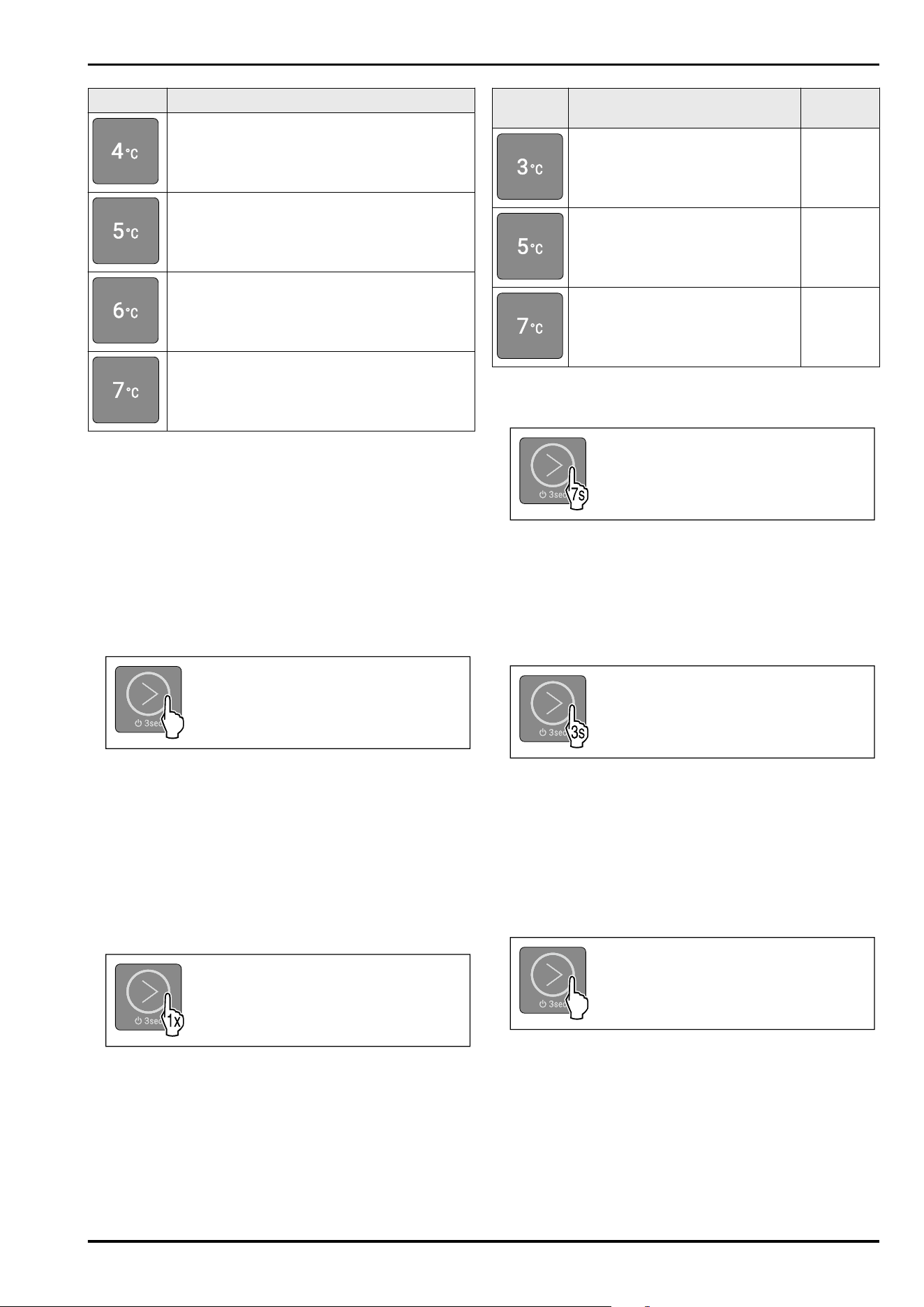
LED Description
Temperature 4°C
Temperature 5°C
Temperature 6°C
Temperature 7°C
Meaning of the LEDs in the main menu
4.2.1 Opening the main menu
When you switch the appliance on, you are automatically in
the main menu.
If you are in the submenu and want to switch to the main
menu:
► Carry out action steps (see4.2.2Exiting the submenu) .
4.2.1 Navigating in the main menu
If you navigate in the main menu, LED 5 is followed by LED 1
again.
Fig.27
► Briefly touch the touch button repeatedly until the LED of
the desired function lights up.
▷ Function is activated.
4.2.1 Sleep mode of thedisplay
If you do not touch the touch button in the main menu for
10 seconds, the display switches to sleep mode. Sleep mode
prevents you from adjusting the temperature by accidentally
touching the touch button.
Ending sleep mode:
Fig.28
► Briefly touch the touch button.
▷ Confirmation tone sounds.
▷ Set temperature flashes once.
▷ Sleep mode is ended.
4.2.2 Submenu
The following functions can be activated/deactivated in the
submenu:
LED
Description LED posi‐
tion
Input lock LED 1
Reset to factory settings LED 3
Select WLAN or LAN. This function
is activated if you fit your appli‐
ance with a SmartModule.
(see 2.3 Special features)
LED 5
Meaning of the LEDs in the submenu
4.2.2 Opening the submenu
Fig.29
► Carry out action steps according to the illustration until a
double confirmation tone sounds after 7seconds.
▷ LEDs 1-5 light up: You are in the submenu.
▷ If you do not perform any action on the display for
5 seconds, the display jumps back to the main menu.
4.2.2 Exiting the submenu
Fig.30
► Carry out action steps according to the illustration.
-or-
► Do not touch the touch button for 5seconds.
▷ You are in the main menu.
4.2.2 Navigating in the submenu
If you navigate in the submenu, LED 1 is followed by the LED
of the last function in the submenu.
Fig.31
► Briefly touch the touch button repeatedly until the LED of
the desired function lights up.
▷ After 5 seconds without interaction, the selected func‐
tion is automatically activated.
Functionality of the display
12 * Depending on model and options
5 Start-up
5.1 Switching on the appliance (first
use)
Make sure that the following requirements are fulfilled:
❑
The appliance has been set up and connected according
to the installation instructions.
❑
All adhesive strips, adhesive and protective films and
transport locks are removed from inside and on the appli‐
ance.
❑
All marketing leaflets are removed from the drawers.
❑
You are familiar with the functionality of the display.
(see4 Functionality of the display)
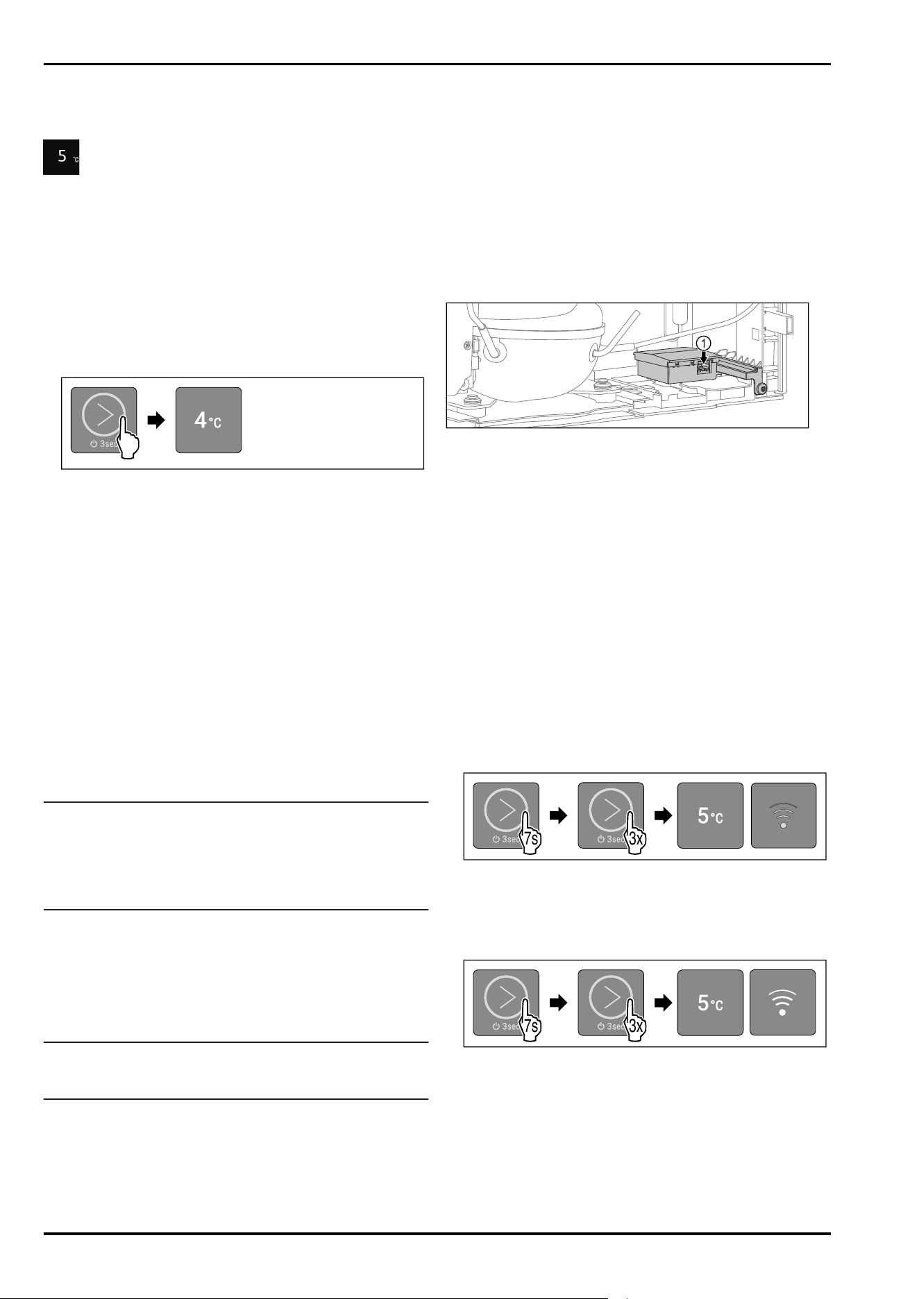
Switch on the appliance:
3s
Fig. 32 For appliances with installed/retrofitted Smart‐
Module
3s
Fig. 33 For appliances without SmartModule
► Touch the touch button according to the illustration for
3 seconds until the confirmation tone sounds.
▷ Appliance is switched on.
▷ Interior lighting is activated.
▷ LED 3 light ups: Temperature is set to 5°C at the factory.
▷ The appliance cools to the target temperature set at the
factory.
▷ If the SmartModule is inserted: WLAN LED is flashing.
WLAN access point is open for 15 minutes.
Appliance starts in demo mode:
If the appliance starts in demo mode:
► Deactivate demo mode. (see Deactivating demo mode)
Display switches to sleep mode:
If the display switches to sleep mode:
► Briefly touch the touch button. (see 4.2.1 Sleep mode of
thedisplay)
6 Storage
6.1 Information regarding storing items
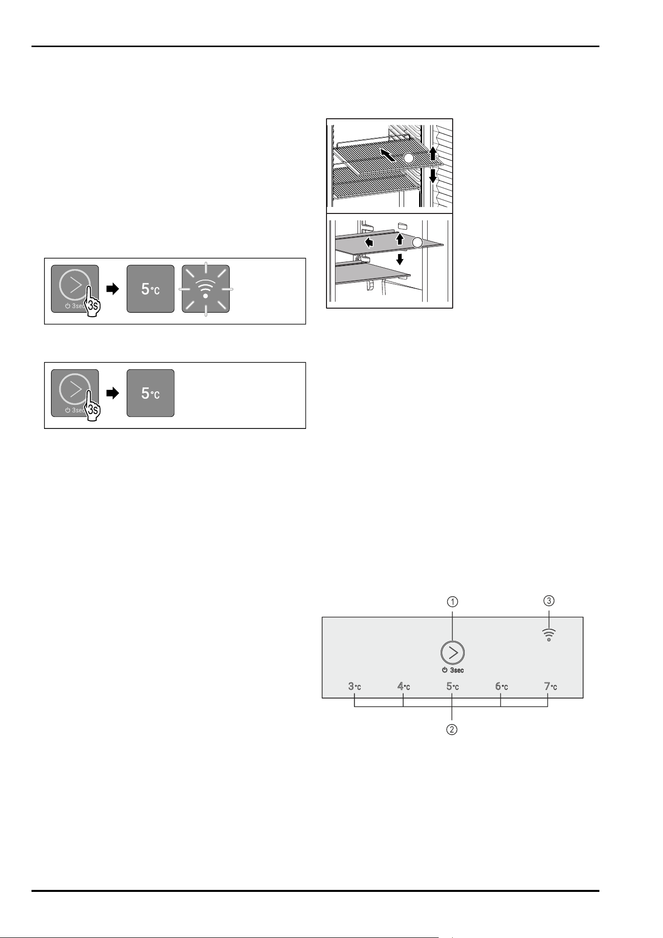
1
1
Fig. 34 Example illustration
When stocking items, observe the following:
❑
If shelves Fig. 34 (1) can be moved, adjust the shelves
according to the height.
❑
Observe maximum load weight. (see 10.1 Technical data)
❑
Do not stock appliance until the storage temperature has
been reached (maintain cold chain).
❑
Refrigerated goods must not touch the rear wall.
❑
Refrigerated goods do not stick out beyond the shelves.
❑
Keep liquids in closed containers.
❑
Leave space when storing items for refrigeration to
ensure adequate air circulation.
7 Use
7.1 Operating and display elements
The display enables a quick overview of the current appli‐
ance status, the temperature setting, the status of func‐
tions and messages.
You operate your appliance using the touch button.
1
2
3
Fig. 35 Example illustration: Display
(1)
Touch button (oper‐
ating element)
(3) WLAN LED
(2) Temperature display/
status display
7.1.1 Temperature display/status display
The temperature display/status display consists of five
LEDs:
Start-up
* Depending on model and options 13
1 2
3
4
5
Fig. 36 Example illustration
(1) LED1 (4) LED4
(2) LED2 (5) LED5
(3) LED3
The LEDs indicate temperature settings in the main menu
(see 4.2.1 Main menu) and functions in the submenu
(see4.2.2Submenu) .
7.1.2 LED behavior
The appliance status can be recognized by the lighting or
flashing of the LEDs:
LED behavior
(example illustra‐
tion)
Description
LED does not light up:
LED is not selected. Function is not
active.
LED light ups:
LED is selected or function is active.
Multiple LEDs flash simultaneously:
Error has occurred.
(see 7.3Messages)
If the SmartModule is inserted and
WLAN LED flashes:
WLAN access point is open or WLAN
connection is being established.
If the SmartModule is inserted and
WLAN LED lights up:
LAN connection is selected.
WLAN LED does not light up:
WLAN connection is selected.
LED behavior
7.1.3 Acoustic signals
An acoustic signal sounds in the following cases:
Acoustic signal
Description
Confirmation
tone
Sounds when you touch the touch
button.
Alarm tone Sounds when an error occurs.
(see 7.3Messages)
Error tone Sounds when you touch the touch
button, but the interaction is not
possible.
7.2 Appliance functions
7.2.1 Notes on the appliance functions
The appliance functions are set at the factory so that your
appliance is fully functional.
Before you alter, activate or deactivate the appliance func‐
tions, make sure that the following requirements are met:
❑
You have read and understood the descriptions of how
the display works. (see4 Functionality of the display)
❑
You have familiarized yourself with the operating and
display elements of your appliance. (see 7.1 Operating
and display elements)
Switching appliance off and on
This function switches the entire appliance on and off.
Switching off the appliance
If you switch off the appliance, the settings that were made
before remain stored.
Make sure that the following requirements are fulfilled:
❑
Handling instructions have been completed.
❑
You are in the main menu. (see 4.2.2 Exiting the
submenu)
Fig.37
► Carry out action steps according to the illustration until a
confirmation tone sounds.
▷ LEDs of the display no longer light up.
▷ Interior lighting is deactivated.
▷ Appliance is switched off.
Switching on the appliance
3s
Fig. 40 Example illustration: For appliances with installed/
inserted SmartModule
3s
Fig. 41 Example illustration: For appliances without Smart‐
Module
► Carry out action steps according to the illustration until a
confirmation tone sounds.
▷ Appliance is switched on.
▷ Interior lighting is activated.
▷ During the first use: The appliance cools to the target
temperature set at the factory.
▷ If the appliance was previously in operation: The appli‐
ance cools to the target temperature set earlier.
▷ If the SmartModule is inserted: During the first use or if
appliance was not previously connected to the WLAN, the
WLAN access point is open for 15 minutes.
Use
14 * Depending on model and options
▷ If the SmartModule is inserted: If the appliance has
already been connected to the WLAN, the appliance will
connect to the WLAN automatically.
Temperature
Use this function to set the temperature.
The temperature depends on the following factors:
-
How often the door is opened
-
How long the door is open
-
The room temperature of the installation site
-
Type, temperature and amount of food
Setting the temperature
The function is located in the main menu at the positions of
LEDs 1-5.
Fig. 43 Example illustration
► Briefly touch the touch button according to the illustra‐
tion repeatedly until the desired temperature lights up.
▷ Temperature is set.
▷ The appliance cools to the set target temperature.
7.2.4 WLAN/LAN
This function allows you to connect your appliance wire‐
lessly (via WLAN) or with a cable (via LAN). You can monitor
the temperature in the appliance via the Liebherr SmartMo‐
nitoring Dashboard. This function also allows you to discon‐
nect or reset the WLAN connection and to switch back and
forth between WLAN and LAN.
If you want to connect your appliance via WLAN or LAN with
the Internet, make sure that the following requirements are
met:
❑
You have purchased SmartModule.
❑
SmartModule is used in the right position. (see 2.2 Over‐
view of appliances and equipment)
Note
You can obtain accessories from our customer service
(see 10.3 Customer Service) or from authorized distributors
using the distributor search function on our service page on
the Internet:
home.liebherr.com
If you would like to use the Liebherr SmartMonitoring Dash‐
board make sure that the following requirements are met:
❑
SmartModule is installed.
❑
A commercial MyLiebherr account has been set up. You
can register at https://my.liebherr.com.
❑
Pull up the Liebherr SmartMonitoring Dashboards:
https://smartmonitoring.liebherr.com.
Note
Liebherr SmartMonitoring Dashboard is not available in all
countries.
Establishing the WLAN connection
Make sure that the following requirements are met:
❑
The appliance has not yet been connected to WLAN!
❑
SmartModule is inserted.
❑
Liebherr SmartMonitoring Dashboard is installed.
❑
Registration has been completed in the Liebherr Smart‐
Monitoring Dashboard app.
► Switch off appliance. (see Switching off the appliance)
► Switch on appliance. (see 5.1 Switching on the appliance
(first use))
▷ WLAN LED is flashing: WLAN access point is open for
15 minutes.
▷ The appliance is attempting to establish a connection
automatically.
▷ If the appliance is connected to the WLAN: WLAN LED
turns off.
Establishing the LAN connection
1
Fig.44
Make sure that the following requirements are met:
❑
The appliance has not yet been connected to LAN!
❑
SmartModule is inserted.
❑
A network cable is connected. Fig.44(1)
❑
The network is connected to the Internet.
► Switch off appliance. (see Switching off the appliance)
► Switch on appliance. (see 5.1 Switching on the appliance
(first use))
▷ WLAN LED is flashing.
► The appliance is attempting to establish a LAN connec‐
tion automatically.
▷ If the appliance is connected to LAN: WLAN LED lights up
continuously.
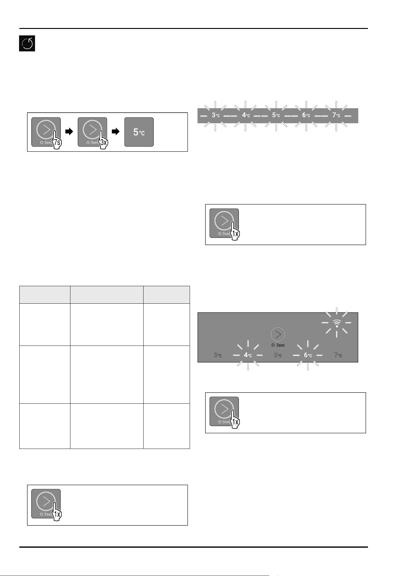
Display connection type
To view the connection type, navigate to the submenu.
(see4.2.2Submenu)
WLAN is active:
3x
7s
Fig.45
► Carry out action steps according to the illustration.
▷ LED 5 lights up.
▷ LED 6 does not light up.
LAN is active:
3x
7s
Fig.46
► Carry out action steps according to the illustration.
▷ LED 5 lights up.
▷ LED 6 lights up.
Switching from a LAN connection to a WLAN connection
Make sure that the following requirements are met:
❑
LAN connection is active.
❑
SmartModule is inserted.
Use
* Depending on model and options 15
► Switch off appliance.
► Remove the network cable.
► Switch on appliance.
▷ The access point is open for 15 minutes.
► Carry out action steps according to the illustration.
3x
7s
1x
Fig. 47
► Carry out action steps according to the illustration.
▷ LED 6 does not light up.
▷ WLAN connection is active.
Switching from a WLAN connection to a LAN connection
Make sure that the following requirements are met:
❑
WLAN connection is active.
❑
SmartModule is inserted.
► Switch off appliance.
► Insert the network cable. Fig.44(1)
► Switch on appliance.
3x
7s
1x
Fig.48
► Carry out action steps according to the illustration.
▷ LED 6 lights up.
▷ LAN connection is active.
Disconnecting the WLAN connection
You can disconnect the WLAN connection by removing the
SmartModule.
► Switch off appliance. (see Switching appliance off and
on)
► Remove the SmartModule.
► Switch on appliance. (see Switching appliance off and
on)
▷ Appliance has restarted.
▷ Appliance is ready with no Internet connection.
Disconnecting the LAN connection
You can disconnect the LAN connection by removing the
network cable.
► Switch off appliance. (see Switching appliance off and
on)
►
Remove the network cable.
► Switch on appliance. (see Switching appliance off and
on)
▷ Appliance has restarted.
▷ The appliance is attempting to establish a WLAN connec‐
tion automatically. (see Establishing the WLAN connec‐
tion)
Note
If you would like to use the appliance without a WLAN
connection, you must disconnect the WLAN connection.
(seeDisconnecting the WLAN connection)
Resetting the WLAN or LAN connection
You can reset the WLAN or LAN connection by resetting the
entire appliance to its default settings. (see Resetting to
factory settings)
Demo mode
Demo mode is a special feature for dealers who want to
demonstrate appliance features. If you activate demo mode,
all refrigeration functions are deactivated and you cannot
open the submenu.
If you activate and then deactivate demo mode, the appli‐
ance will be reset to factory settings. (see Resetting to
factory settings)
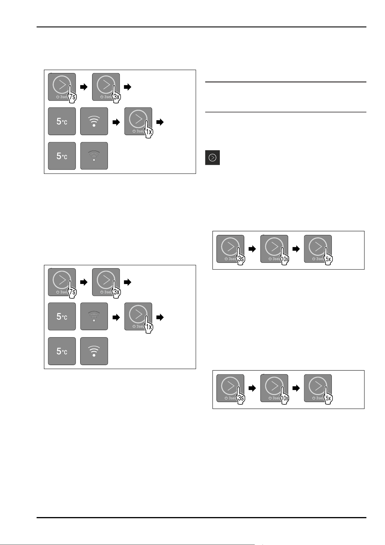
Activating demo mode
4x
3s
10s 5x
Fig. 49
► Touch the touch button according to the illustration for
3 seconds until the confirmation tone sounds.
▷ Appliance is switched off.
► Touch the touch button according to the illustration for
10 seconds until the confirmation tone sounds after
10seconds.
► Briefly touch the touch button five times.
▷ All temperature LEDs briefly light up twice: Demo mode is
activated.
▷ Appliance is switched off.
► Switch on appliance. (see Switching on the appliance)
▷ Appliance is in demo mode.
Deactivating demo mode
4x
3s
10s 5x
Fig.50
► Touch the touch button according to the illustration for
3 seconds until the confirmation tone sounds.
▷ Appliance is switched off.
► Touch the touch button according to the illustration for
10 seconds until the confirmation tone sounds after
10seconds.
► Briefly touch the touch button five times.
▷ All temperature LEDs light up four times: Demo mode is
deactivated.
▷ Appliance is switched off.
► Switch on appliance. (see Switching on the appliance)
Use
16 * Depending on model and options
Resetting to factory settings
Use this function to reset all settings to factory settings. All
settings you have made so far (such as login data) are reset
to their original settings.
Application:
-
Resetting the appliance
Performing a reset
3x7s
Fig. 51 Example illustration
► Carry out action steps according to the illustration.
▷ LED 3 light ups.
▷ After 5 seconds without interaction, the appliance is
reset.
▷ Appliance is switched off.
► Switch on the appliance. (see 5.1 Switching on the appli‐
ance (first use))
▷ You can reset login data.
7.3 Messages
Messages are indicated acoustically by an alarm tone and
visually by a flashing of the LEDs in the display. Different
LEDs flash depending on the type of message.
You can end the following messages yourself. For all other
messages, you must contact Customer service.
(see 10.3 Customer Service)
Message
Cause Ending the
message
Alarm tone
sounds.
Interior lighting
pulses.
Door alarm
The message appears if
the door is open for
more than 60seconds.
Carry out
action steps
(see Door
alarm) .
LEDs 1-5 flash.
Alarm tone
sounds.
Interior lighting
pulses.
Temperature
alarm
The message appears if
the temperature does
not correspond to the
set temperature.
Carry out
action steps
(see Tempera‐
ture alarm) .
LED 2, LED 4
and WLAN LED
flash.
WLAN error
The message appears if
the appliance could not
be connected to the
WLAN or if the WLAN
connection is inter‐
rupted.
Carry out
action steps
(see WLAN
error) .
Overview of messages
7.3.1 Ending messages
Door alarm
Fig.52
►
End alarm: Carry out action steps according to the
illustration.
-or-
► Close the door.
▷ Alarm is ended.
▷ If you do not close the door: Message will appear again
after 1 minutes.
Temperature alarm
Fig. 53 Display in the event of a temperature alarm
Possible causes for temperature differences:
-
You have put in warm, fresh food.
-
Too much warm room air has flowed in during the rear‐
rangement and removal of food.
-
The power has been out for a longer period of time.
-
The appliance is defective.
► Remedy the cause.
Fig.54
► End alarm: Carry out action steps according to the
illustration.
▷ Appliance continues to run in normal operation.
▷ LED of the previously set temperature flashes until
temperature is reached.
WLAN error
Fig. 56 Display in the event of a WLAN error
► Check the WLAN connection.
Fig.57
► End alarm: Carry out action steps according to the
illustration.
-or-
► Reestablish the WLAN connection.
▷ Appliance continues to run in normal operation. LED of
the previously set temperature lights up.
Use
* Depending on model and options 17
8 Equipment
8.1 Safety lock
The lock in the appliance door is equipped with a safety
mechanism.
8.1.1 Locking appliance
Fig. 58 Example illustration
► Insert key.
► Turn key anticlockwise by 90°.
▷ The appliance is locked.
8.1.2 Unlocking appliance
Fig. 59 Example illustration
► Insert key Fig. 59(1).
► Turn key clockwise by 90° Fig. 59(2).
▷ The appliance is unlocked.
8.2 Sensors
The appliance can be equipped with the following sensors
for temperature monitoring:
-
C sensor
8.2.1 C sensor (control sensor)
The C sensor is permanently installed in the interior of the
appliance.
9 Maintenance
9.1 Maintenance schedule
Maintenance work is to be performed at regular intervals to
ensure proper appliance function.
CAUTION
Danger of injury and damage due to unprofessional mainte‐
nance work!
Personal injury and material damage.
► Maintenance work may only be performed by trained
specialist personnel.
WARNING
Short-circuit hazard due to live parts!
Electric shock or damage to the electronics.
► Switch off the appliance.
► Pull out mains plug or switch off fuse.
Note
We recommend creating a maintenance log in which all
work (repairs, checks) performed is documented.
Note
Liebherr recommends yearly maintenance. For an individual
offer, please contact Customer Service (see 10.3 Customer
Service) .
Component Activity Maintenance interval
Sheet metal parts Check for damage and corrosion.
Replace damaged parts: (see 10.3 Customer Service)
Yearly
Door, hinges Check alignment (see 3.6 Aligning the door) , ease of
movement, and tight fit.
Yearly
Lock, door handle * Check for ease of movement and tight fit. Yearly
Door seal Check for damage, wear, and tight fit.
A replacement door gasket is available via Customer
Service (see 10.3 Customer Service) .
Yearly
Sensor feedthrough Check that the sealing compound is intact. Yearly
Surfaces Cleaning (see 9.3Cleaning the appliance) Recommendation: monthly or as
required/specified at installa‐
tion location
Equipment
18 * Depending on model and options
Component Activity Maintenance interval
Surfaces Disinfection
Liebherr has tested the following disinfectants:
Dismozon pur 1 % Lösung (Bode Chemie), Suma
Quicksan (Diversey), Incidin Extra N (Ecolab Health‐
care), Acrylan (Antiseptica chem.-pharm. Produkte),
Buraton 10 F (Schülke und Mayr), Frankocid N
(Franken Chemie), Apesin DSR 50 (Tana), Nüscosept
Spray (Dr. Nüsken), Melsept SF (B. Braun Melsungen),
Kohrsolin (Bode Chemie), Neoquat S (Dr. Weigert),
Indicin Rapid (Ecolab Healthcare), Bacillocid Spezial
(Bode Chemie), Neoform K Spray (Dr. Weigert), Apesin
Desinf. Spray (Tana), Nüscosept 100 (Dr. Nüsken),
Antisept T (Fink Tec), Apesin AP 100 0,50% Lösung
(Tana), Perform Pulver 2% Lösung (Schülke und Mayr)
Observe the operating instructions of the respective
manufacturer. If disinfectants other than those
stated are used, test them on a less exposed area
first.
Recommendation: monthly or as
required/specified at installa‐
tion location
Installation location, appliance Decontamination
The appliance is suitable for room decontamination
with hydrogen peroxide H
2
O
2
.
In this context, the values of the following applica‐
tion specifications must not be exceeded:
Concentration: maximum 250 ppm.
Humidity: maximum 85%.
Maximum permissible room temperature as per
climate class. (see2.4 Range of appliance use)
Recommendation: as required/
specified at installation location,
maximum 2x per year
Network cable Check for damage. Annually
or
when changing the location
9.2 Defrosting the appliance
WARNING
Appliance incorrectly defrosted!
Injuries and damage.
► Do not use mechanical devices or other means to accel‐
erate the defrosting process, other than those recom‐
mended by the manufacturer.
► Do not use any electrical heating or steam cleaning
equipment, naked flames or defrosting sprays.
► Do not remove ice with sharp objects.
Defrosting is performed automatically. The water from the
defrosting process runs out via the drain opening and is
evaporated.
To maintain the functionality of the appliance, we recom‐
mend defrosting it when there is a high buildup of ice. Icing
in the interior is determined by the location (e.g. high
humidity), settings on the appliance and incorrect user
behavior.
If automatic defrost is not sufficient, defrost the appliance
manually:
► Switch off appliance. (see Switching appliance off and
on)
► Disconnect power plug.
► Store refrigerated items elsewhere.
► Leave the appliance door open during defrosting process.
► Soak up remaining defrost water with a cloth, clean the
drain opening and the appliance.
9.3 Cleaning the appliance
9.3.1 Preparing
WARNING
Short-circuit hazard due to live parts!
Electric shock or damage to the electronics.
► Switch off the appliance.
► Pull out mains plug or switch off fuse.
WARNING
Danger of fire
► Do not damage the refrigerant circuit.
►
Empty the appliance.
► Pull out the power plug.
► Observe the notes on appliance transport.
9.3.2 Cleaning the housing
NOTICE
Improper cleaning!
Damage to the appliance.
► Only use soft cleaning cloths and ph-neutral all-purpose
cleaners.
► Do not use steel wool or sponges that scour or scratch.
► Do not use caustic or abrasive cleaning materials or
those containing sand, chloride, or acids.
Maintenance
* Depending on model and options 19
WARNING
Risk of injury or damage due to hot steam.
Hot steam can cause scalding/burns and damage to
surfaces.
► Do not use steam cleaners.
NOTICE
Risk of damage due to short circuit.
► When cleaning the appliance, make sure no water gets
into the electrical components.
► Wipe the housing down with soft, clean cloth. If very
dirty, use lukewarm water with a neutral cleaner. Glass
surfaces can also be cleaned with glass cleaner.
► Clean the condenser coil every year. If the condenser coil
is not cleaned, this significantly reduces the efficiency of
the appliance.
9.3.3 Cleaning the interior
WARNING
Short-circuit hazard due to live parts!
Electric shock or damage to the electronics.
► Switch off the appliance.
► Pull out mains plug or switch off fuse.
WARNING
Risk of injury or damage due to hot steam.
Hot steam can cause scalding/burns and damage to
surfaces.
► Do not use steam cleaners.
NOTICE
Improper cleaning!
Damage to the appliance.
► Only use soft cleaning cloths and ph-neutral all-purpose
cleaners.
► Do not use steel wool or sponges that scour or scratch.
► Do not use caustic or abrasive cleaning materials or
those containing sand, chloride, or acids.
Note
► Defrost water drain (see 2.2 Overview of appliances and
equipment) : Remove deposits using a thin object (e.g. a
cotton bud).
Note
Do not damage or remove the type plate on the inside of the
appliance. The type plate is important for Customer Service.
(see 10.3 Customer Service)
► Open the door.
► Empty the appliance.
► Clean the interior and equipment parts with lukewarm
water and a little dish detergent. Do not use any gritty or
acidic cleaning agent or any chemical solvent.
9.3.4 After cleaning
► Wipe the appliance and equipment parts dry.
► Connect and switch on appliance.
When the temperature is sufficiently cold:
► Place in items for refrigeration.
► Clean regularly.
► Clean the refrigeration machine with heat exchanger and
remove dust from it once a year.
10 Customer support
10.1 Technical data
Temperature range
Cooling +3°C to +7°C
Maximum load per shelf
A)
Appliance width 550mm 600mm 750mm
Grid shelves -- 45 kg 60 kg
Glass shelf 40 kg 40 kg 40 kg
Drawer (freezers) 15 kg 15 kg 15 kg
A)
Heavier loads may result in a slight bending of the
shelves.
Maximum total load and net weight
Model (see 3.2 Appliance
dimensions)
Maximum total
load
Net weight
SRC.. 801 120 kg 27.8 kg
Net capacity
See net capacity on the type plate. (see 2.2 Overview of
appliances and equipment)
Lighting
Energy efficiency class
A)
Light sources
This product contains one or more energy
efficiency class G light sources
LED
A)
The appliance may contain light sources with different
energy efficiency classes. The lowest energy efficiency
class is indicated.
WLAN frequency specification
Frequency band 2.4GHz
Maximum radiated power <100 mW
Purpose of the wireless
equipment
Integration in the local WiFi
network for data communi‐
cation
Setup conditions
Degrees of pollution (surrounding
the appliance)
PD2
Ambient temperature +10°C to +35°C
Maximum relative ambient moisture 75%, not condensing
Maximum operating elevation
(meters above sea level)
2000m
Electrical values
Nominal voltage 220-240 V~
Frequency 50Hz
Connected load 1,3A
Maximum power supply fluctuation +/-10%
Overvoltage categories II
Customer support
20 * Depending on model and options
10.2 Technical malfunction
Your appliance is designed and built to ensure it works reli‐
ably and has a long service life. If a malfunction nonethe‐
less occurs during operation, please check whether the
malfunction is due to an operating error. If this is the case,
you will be charged for the cost incurred even if this falls
within the warranty period.
You can rectify the following malfunctions yourself.
10.2.1 Appliance function
Defect Cause Remedy
The appliance is
not working.
→ The appliance is not switched on. ► Switch on the appliance.
→ The power plug is not properly
inserted in the socket.
► Check the power plug.
→ There is a problem with the wall
socket breaker.
► Check the breaker.
→ Power failure ► Keep the appliance closed.
► If necessary move the refrigerated/frozen items to
another fridge or freezer if the power is off for a
prolonged period.
→ The IEC socket is not correctly
plugged into the appliance.
► Check the IEC socket.
The temperature is
not cold enough.
→ The appliance door is not closed
properly.
► Close the appliance door.
→ Ventilation is not sufficient. ► Unclog the ventilation grill and clean it.
→ The ambient temperature is too
high.
► Observe the suitable ambient conditions: (see 2.4 Range
of appliance use)
→ The appliance was opened too
many times or for too long.
► Wait to see if the required temperature corrects itself. If
not, contact Customer Service. (see 10.3 Customer
Service)
→ The temperature is set incorrectly. ► Set a colder temperature and check after 24 hours.
→ The appliance is too close to a heat
source (stove, heater etc).
► Move either the appliance or the heat source.
10.3 Customer Service
First check whether you can remedy the fault yourself . If
this is not the case, please contact Customer Service.
You can find the address in the enclosed brochure “Liebherr-
Service” or at home.liebherr.com/service.
WARNING
Unprofessional repair!
Injuries.
► Repairs and work on the appliance and the power supply
cable not described in the Manual (see 9 Maintenance)
should only be carried out by a qualified service provider.
► A damaged power cable may only be replaced by the
manufacturer, the manufacturer’s Customer Service or a
similarly qualified person.
► For appliances with an IEC connector, the change can be
made by the customer.
10.3.1 Contacting Customer Service
Make sure you have the following appliance information
ready:
❑
Appliance name (model and index)
❑
Service no. (service)
❑
Serial no. (S no.)
-or-
► Refer to the type plate for appliance information.
(see 10.4 Type plate)
► Note appliance information.
► Inform Customer Service: Report faults and the appliance
information.
▷ This will help us to provide fast and focused service.
► Follow any further instructions provided by Customer
Service.
10.4 Type plate
The type plate is inside the appliance. See appliance over‐
view.
Fig.60
(1)
Appliance designation (3) Serial No.
(2) Service No.
11 Shutting down
► Empty the appliance.
► Switch off appliance.
► Pull the power plug from the outlet.
► If necessary, remove the IEC socket: Pull the IEC socket
out of the appliance plug while turning it to the left and
right at the same time.
Shutting down
* Depending on model and options 21
► Clean the appliance. (see 9.3Cleaning the appliance)
► If available: Remove the covers and insulation of the
sensor feed-through to prevent mold from forming.
► Leave the door open so that no bad odors form.
Note
Damage to the appliance and malfunctions!
► After shutting down, only store the appliance at the
permitted room temperature of between -10 °C and
+50°C.
12 Disposal
12.1 Preparing appliance for disposal
Liebherr uses batteries in some of its appli‐
ances. In the EU, for environmental reasons,
legislation obliges the end user to remove
these batteries before disposing of the old
appliances. If your appliance contains
batteries, a corresponding notice is attached to
the appliance.
Lamps If you can remove the lamps yourself without
destroying them, also remove these before
disposal.
► Take the appliance out of operation.
► If possible: Remove lamps without destroying them.
12.2 Disposing of the appliance in an
environmentally friendly manner
The appliance still contains
valuable materials and must be
collected separately from
unsorted municipal waste so it
can be recycled.
Dispose of batteries separately
from the old appliance. You can
do this by returning the
batteries free of charge to
retailers or taking them to recy‐
cling centers and collection
centers for recyclable materials.
Lamps Dispose of removed lamps via
the respective collection
systems.
For Germany: You can dispose of the appli‐
ance free of charge via the class
1 collection containers at the
local recycling and recyclable
material collection centers.
When purchasing a new fridge/
freezer, if the sales area > 400
m
2
, retailers will also take back
the old appliance free of charge.
WARNING
Leaking refrigerant and oil!
Fire. The refrigerant contained within the appliance is envi‐
ronmentally friendly, but flammable. The oil contained
within the appliance is flammable. Escaping refrigerant and
oil can ignite if they are of high enough concentration and
are exposed to an external heat source.
► Do not damage the pipelines of the coolant circuit and
the compressor.
► Observe the notes on appliance transport.
► Transport the appliance away without damaging it.
► Dispose of batteries, lamps, and the appliance according
to the above specifications.
13 Additional information
Further information on warranty conditions can be found in
the enclosed service brochure or on the Internet at https://
home.liebherr.com.
Disposal
22 * Depending on model and options

Additional information
* Depending on model and options 23
home.liebherr.com/fridge-manuals
Table-height refrigerator
ORIGINAL OPERATOR'S MANUAL
Issue date: 20260210
Part number index:7086806-00
Liebherr-Hausgeräte Marica EOOD
Bezirk Plovdiv
4202 Radinovo
Bulgarien