Lift out foam packed hardware
3-Installation
IMPORTANT: You must read the installation and owner’s manual provided with the grill.
These quick start instructions assume a natural gas or household propane congured unit. See main instructions for propane cylinder units.
Note: This section is only an overview of installation to the gas supply. Refer to the grill owner’s manual for complete grill installation details.
Turn OFF the gas supply at the source. Route the attached ex connector with regulator (located underneath the grill) to the gas supply stub. (An adapter is
required if the gas supply stub is other than
1
/
2
” in diameter.) Then connect the regulator to the gas supply stub. Use pipe joint compound that is resistant to all
gasses on the male pipe tting and tighten securely. DO NOT use pipe joint compound to connect are ttings. See Fig. 3-5.
Turn all burner control knobs to the OFF position. Turn the gas supply on. Then carefully check all gas connections for leaks with a brush and half-soap/half-water
solution before lighting. NEVER USE A MATCH OR OPEN FLAME TO TEST FOR LEAKS.
Refer to the INSTALLATION REQUIREMENTS section of your grill owner’s manual
for complete details.
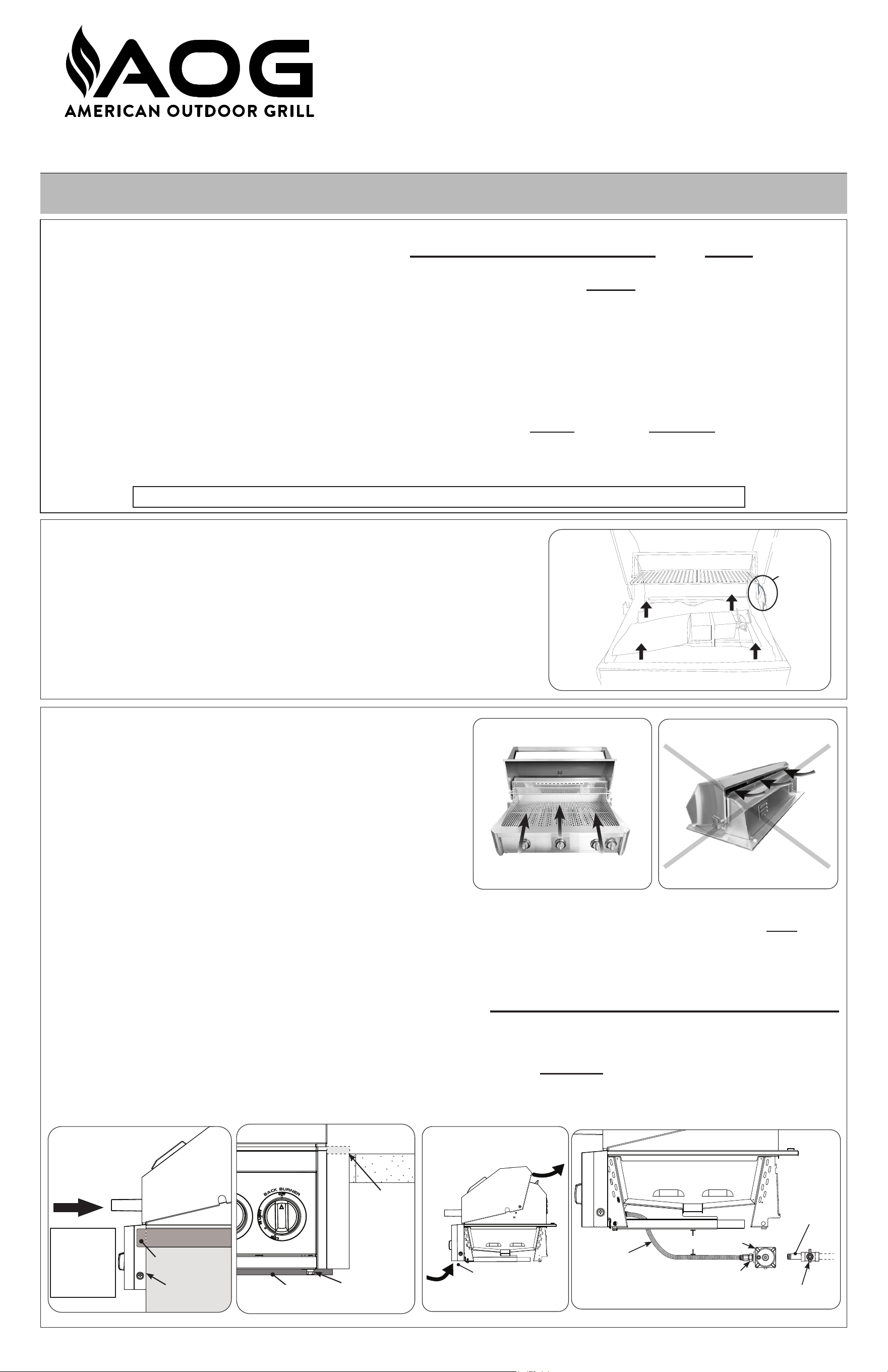
CAUTION: Wind blowing into or across the rear oven lid vent (Fig. 3-2) can
cause poor performance and/or dangerous overheating. Orient
the grill so that the prevailing wind blows toward the front of the
grill (Fig. 3-1).
CAUTION: To prevent dangerous overheating, the rear of the unit must have a
minimum clearance of 4” from any backsplash/non-combustible wall.
INSTALLER: Leave these instructions with consumer. CONSUMER: Retain for future reference.
This grill must be installed in accordance with local codes and ordinances, or, in the absence of local codes, with either the latest National Fuel Gas Code (ANSI
Z223.1/NFPA 54), and Natural Gas and Propane Storage and Handling Installation Code (CSA-B149.1).
This appliance and its individual shuto valves must be disconnected from the gas-supply piping system when testing the system at pressures in excess of ½ psig.
This appliance must be isolated from the gas-supply piping system by closing its dedicated manual shuto valve during any pressure testing of the gas-supply
system at pressures up to and including ½ psig.
This unit is designed for outdoor use only. DO NOT use this unit inside a building, garage, or enclosed area (see paragraph below). DO NOT use this
unit in or on a recreational vehicle or boat.
Important: If installing this unit in a COMBUSTIBLE enclosure, the correct AOG insulating liner must be used. Consult the liner instructions for
cutout dimensions and installation.
A minimum 5 foot clearance is required between the countertop and the overhead construction. DO NOT install under combustible overhead construction
without a suitable UL710 or ULCS646 approved heavy duty vent hood. When installed under non-combustible overhead construction, an exhaust hood is
highly recommended. When using an exhaust hood: the area above the cooking surface of the grill must be covered with a hood larger than the cooking area of
the grill, and with a minimum of 1200 CFM (cubic feet per minute) for proper outdoor application. Custom spacers must be constructed entirely of non-combustible
materials only. Custom sots may be constructed of wood, metal framing, etc.
2-Unpacking
Carefully unpack the unit, removing all packing material and protective lm. Verify that
all parts have arrived undamaged by consulting the parts list in the owner’s manual.
Remove foam packed hardware. (See Fig. 2-1.)
Consult the parts list in the owner’s manual. If any parts are missing or damaged,
immediately contact the AOG dealer before beginning installation.
Fig. 2-1
1-Safety
Location
Connect Gas Supply
Installation must be performed by a qualified professional service technician.
CAUTION: WHEN INSTALLING UNIT, BE AWARE OF ENCLOSURE REQUIREMENTS; YOU MUST VENT UNIT
IN ACCORDANCE WITH YOUR OWNER’S MANUAL. FAILURE TO DO SO MAY RESULT IN A FIRE OR
EXPLOSION CAUSING PROPERTY DAMAGE, BODILY INJURY, OR DEATH.
Remove plastic
zip-ties
Slide the unit into the enclosure cutout. The control panel must be ush with the enclosure face as shown in Fig. 3-4.
Proper grill airow (front-to-back) must be maintained as shown in Fig. 3-6. Do not block the front air inlet. It is not necessary to remove the control panel or knobs
for installation.
Grill Placement
REV 0 - A- 2511200835
L-C2-772
Built-in Outdoor
Gas Grill Quick Start Guide
"L" & "T" Series
Fig. 2-1
Lift out foam packed hardware
Remove
plastic
zip-ties
Fig. 3-2
Fig. 3-3
Fig. 3-6
Fig. 3-5
Fig. 3-1
Flex
connector
Flare-to-NPT adapter
Regulator
6" Grill
clearance
Gas supply
(NPT)
Shut-o valve (shown in-line) must be installed within
6 feet of the unit and must be easily accessible
Hanger must
rest ush on
countertop
Ensure front
panel is ush
Countertop
Overhang
SLIDE IN
(be careful
when inserting
power supply
harness, if
equipped)
CORRECT
PLACE GRILL SO PREVAILING WIND
BLOWS TOWARD FRONT OF GRILL
YOU MUST PROTECT REAR OVEN
VENT FROM PREVAILING WIND
Rear oven lid vent
INCORRECT
Front air inlet
(do not block)
Slide the unit into the enclosure cutout. The front panel must be ush with the enclosure face as shown in Fig. 3-3. The front support adjustment bolts MUST be used
to provide support to the hangers. See Fig. 3-4.
Proper grill airow (front-to-back) must be maintained as shown in Fig. 3-5. Do not block the front air inlet. It is not necessary to remove the front panel or knobs
for installation.
Fig. 3-4
Adjust bolt to
touch lower
support
Lower support
of front cutout
6-Propane and Natural Gas Safety
FOR PROPANE CONFIGURATIONS; READ ALL SAFETY INSTRUCTIONS AND WARNINGS REGARDING THE USE
OF PROPANE GAS FOUND IN YOUR OWNER’S MANUAL. FOR NATURAL GAS READ ALL SAFETY INSTRUCTIONS
AND WARNINGS FOUND IN YOUR OWNER’S MANUAL.
7-Routine Maintenance
Your grill must be serviced and maintained properly to ensure optimal performance, appearance, and safety. Clean you grill before
and after each use. Additionally, a deep clean of the entire grill and all its components MUST be performed twice a year (or as needed
depending on use). See owner’s manual for details.
REV 0 - A- 2511200835
L-C2-772
4-Grill Setup
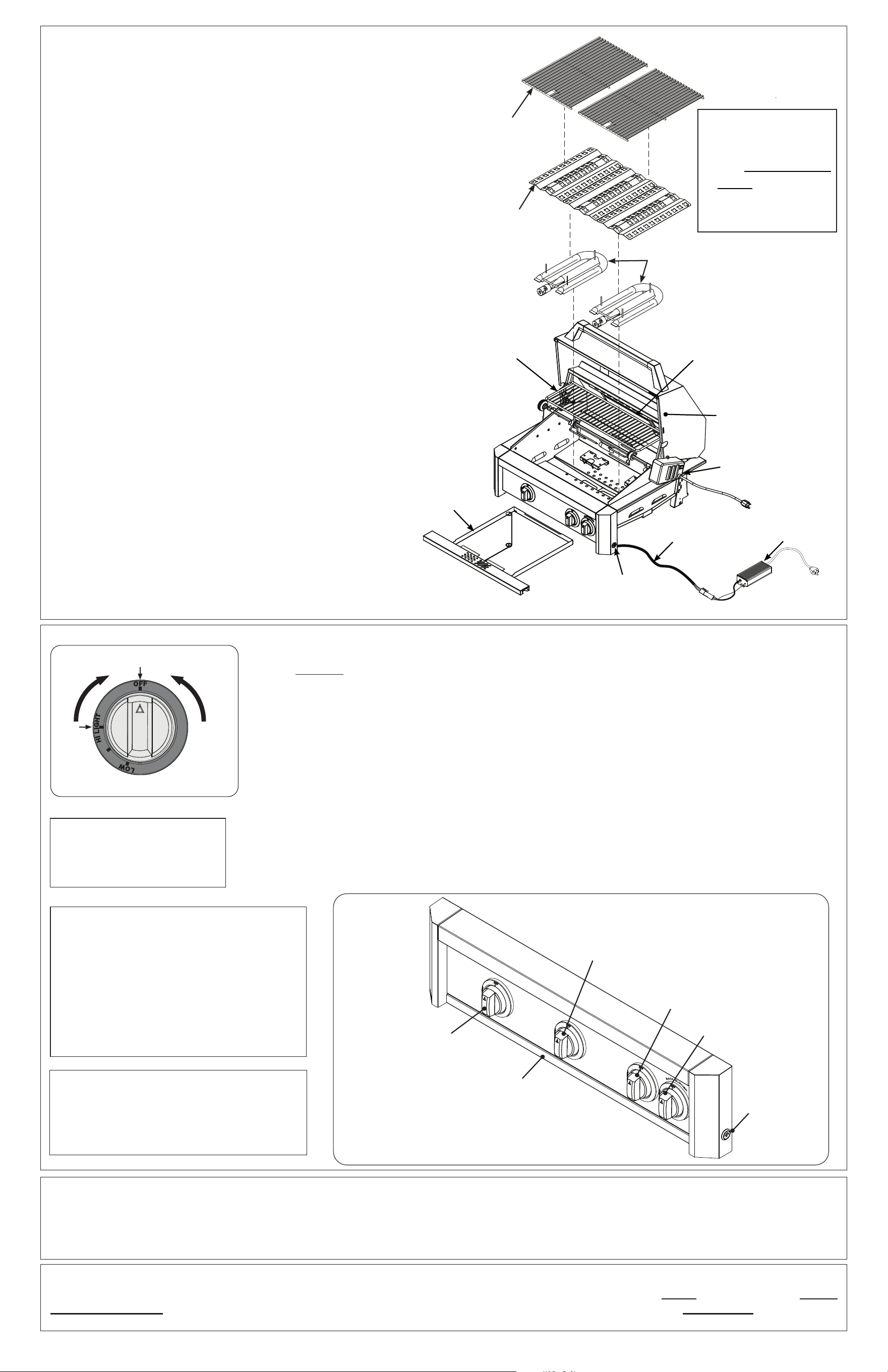
Parts Placement Checklist
Place the following items according to their position and
orientation in Fig. 4-1:
Vaporizer panels, cooking grids, and drip tray.
Leave pre-installed burners in place to maintain proper
alignment.
Vaporizer Panels
Place the vaporizer panels directly onto the studs on the
burners. The panels allow heat from the burners to be evenly
distributed throughout the cooking area.
Cooking Grids
Place the cooking grids (over the burners) onto the grill frame.
Drip Tray
Fully insert the drip tray into the bottom front of the front panel.
IMPORTANT: See your grill owner’s manual for complete
installation details.
Fig. 4-1
Cooking grid
Vaporizer panel
Backburner
(if equipped)
Warming
rack
Rotisserie kit
(if equipped)
Power
supply
Wire harness
extension
Drip tray
Light switch
(if equipped)
Grill lights
(not shown)
Main burner
*
Note: DO NOT turn on more than one valve at a time for either electronic or manual lighting.
1. Open lid(s) or remove cover(s) from burner(s) to be lit.
2. Turn all gas control knob(s) to their OFF position(s).
3. Turn on the gas at its source.
4. Depress the desired control knob, and while pressing turn it counterclockwise to the HI LIGHT position.
Once the burner lights, release the knob.
Note: Turning the knob will create a “click” sound and ignite the burner. If there is no ignition, immediately turn
to OFF position and repeat sequence quickly until the burner ignites.
CAUTION: If a burner does not light within ve (5) seconds of turning on the control knob, depress the
knob and turn it to the OFF position. WAIT FIVE (5) MINUTES before repeating step 4. If you
smell gas, follow the instructions on the cover of this manual. If the burners still do not light after
several attempts, refer to the instructions for manual lighting.
5. Repeat step 4 for each additional burner to be lit.
5-Test
WHEN OPERATING THIS GAS
APPLIANCE, ALL INSTRUCTIONS
AND WARNINGS MUST BE
OBSERVED. FAILURE TO DO
SO MAY RESULT IN A FIRE OR
EXPLOSION CAUSING PROPERTY
DAMAGE, BODILY INJURY, OR
DEATH.
30" and 36" L-series model
If equipped, the light switch is push
button operated, and is located on the
right side of the front panel (see Fig.
5-2). It controls the power to all lights.
If equipped, see your
grills owner's manual for
LED light operation.
Replacement parts can be ordered
from your local AOG dealer.
‡
*
The burner ports
and carry-over
slots must be kept
clean to ensure
proper ignition and
operation.
Fig. 2-1 Control knob
Read setting here
(OFF position shown)
To Turn OFF
To Turn ON
Use HI
(high) to
light
Press
knob in
to turn
Center main burner
control knob
Left main burner
control knob
Right
main burner
control knob
Backburner
control knob
(L-Series models only)
Drip tray
(L-Series shown)
Light switch*
(L-Series models
only)
Fig. 5-2