1
Hearth & Home Technologies • Stadium Installation Manual • 4004-900 Rev. B • 03/25
Installation Manual
Installation and Appliance Setup
NOTICE: DO NOT discard this manual!
In the Commonwealth of Massachusetts
installation must be performed by a licensed
plumber or gas fitter.
See appliance installation manual for
additional Commonwealth of Massachusetts
requirements.
INSTALLER: Leave this manual with party responsible for use and operation.
OWNER: Retain this manual for future reference.
• DO NOT store or use gasoline or other flam-
mable vapors and liquids in the vicinity of this
or any other appliance.
• What to do if you smell gas
- DO NOT try to light any appliance.
- DO NOT touch any electrical switch. DO
NOT use any phone in your building.
- Leave the building immediately.
- Immediately call your gas supplier from a
neighbor’s phone. Follow the gas supplier’s
instructions.
- If you cannot reach your gas supplier, call
the fire department.
• Installation and service must be performed
by a qualified installer, service agency, or the
gas supplier.
WARNING:
FIRE OR EXPLOSION HAZARD
Failure to follow safety warnings exactly
could result in serious injury, death, or
property damage.
Model(s):
2TR-IPI-R18-N; 2TR-IPI-R18-P
2TR-IPI-R24-N; 2TR-IPI-R24-P
2TR-IPI-R30-N; 2TR-IPI-R30-P
3TR-IPI-R18-N; 3TR-IPI-R18-P
3TR-IPI-R24-N; 3TR-IPI-R24-P
3TR-IPI-R30-N; 3TR-IPI-R30-P
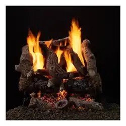
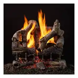
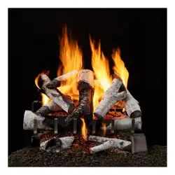
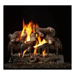
Stadium Series
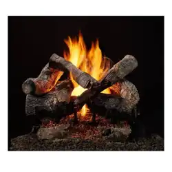
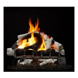
Vented Gas Log Set
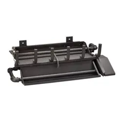
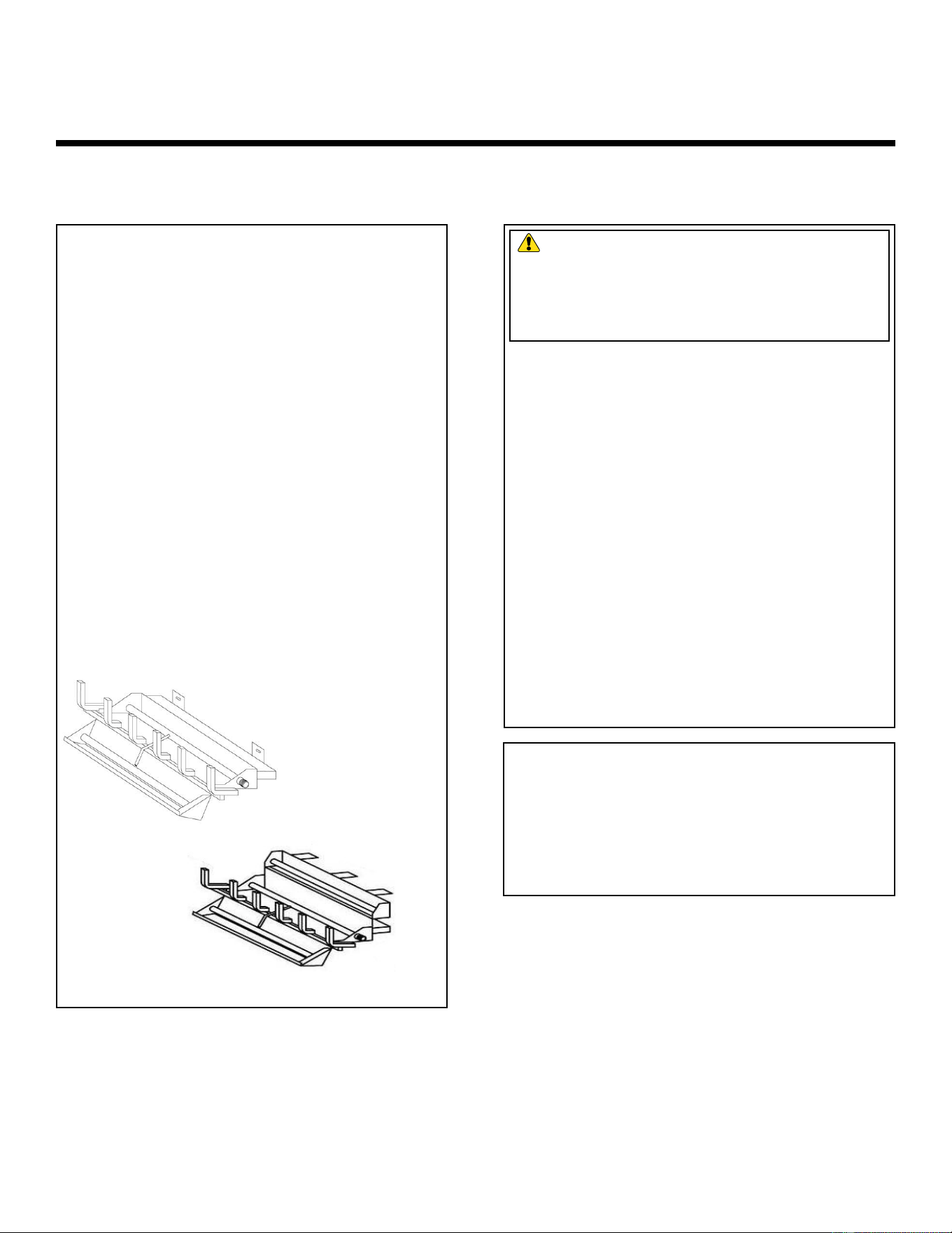
3 Tier Burner
2 Tier Burner

Hearth & Home Technologies • Stadium Installation Manual • 4004-900 Rev. B • 03/25
2
Safety Alert Key:
• DANGER! Indicates a hazardous situation which, if not avoided will result in death or serious injury.
• WARNING! Indicates a hazardous situation which, if not avoided could result in death or serious injury.
• CAUTION! Indicates a hazardous situation which, if not avoided, could result in minor or moderate injury.
• NOTICE: Used to address practices not related to personal injury.
Table of Contents
► = Contains updated information
Installation Standard Work Checklist ....................3
1 Welcome
A. Congratulations ................................. 4
B. Limited Lifetime Warranty ..........................5
2 Product Specific and Important Safety Information
A. Appliance Certification ............................7
B. BTU Specifications and Weight .....................7
C. Gas Pressures ..................................7
D. High Altitude Installations ..........................7
E. Fuel ..........................................7
F. Glass Doors ....................................7
G. California ...................................... 7
H. Requirements for the Commonwealth of Massachusetts . . 8
3 Important Safety and Operating Information
A. Appliance Safety ................................9
B. General Operating Parts ............................9
4 Getting Started
A. Design and Installation Considerations ...............10
B. Tools and Supplies Needed .......................10
C. Inspect Appliance and Components .................10
D. Check Parts ...................................10
E. Minimum Hearth Dimensions ...................... 11
F. Installation Information ........................... 11
G. Adequate Combustion Ventilation Air ................12
H. Negative Pressure ..............................12
5 Gas Information
A. Fuel Type .....................................14
B. Gas Pressure ..................................14
C. Gas Connection ................................14
D. Verify Gas Pressure .............................15
6 Electrical Information
A. Wiring Requirements ............................16
7 Appliance Installation and Set-up
17
.................
17
A. Positioning the Appliance.............. . . . . .
B. On/Off Switch and Remote Control
........................
E. Log Placement ................................
19
F.
Before Lighting Appliance. . . . . . . . . . . . . . . . . . . . . . . ... 20
20
H. Initial Use
20
8 Lighting Instructions
A. Intermittent Pilot (IPI) ............................21
9 Maintenance and Service
A. Maintenance: Frequency and Tasks .................22
B. Maintenance Tasks: Qualified Service Technician ......22
C. Cleaning and Servicing ..........................23
10 Troubleshooting
A. Frequently Asked Questions ......................24
B. Troubleshooting ................................24
11 Service Parts
A. Service Parts
....................................
26-31
B. Contact Information .............................
32
C.
D.
Natural Gas Set-up. . . . . . . . . . . . . . . . . . . . . . . . . . . . .. 18
Propane (LP) Gas Set-u.....................................................19
G. Flame Appearance
3
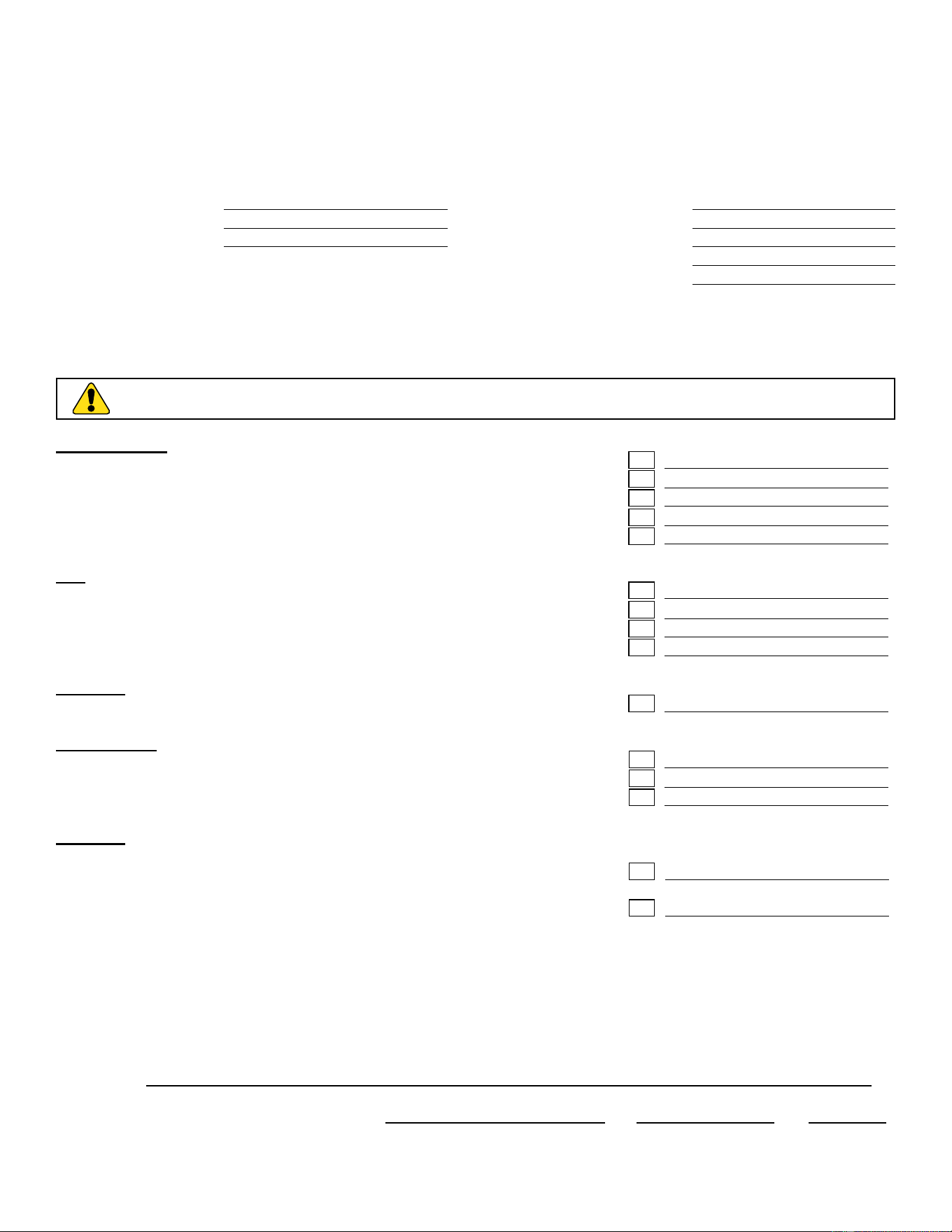
Installation Standard Work Checklist
ATTENTION INSTALLER:
Follow this Standard Work Checklist
This standard work checklist is to be used by the installer in conjunction with, not instead of, the instructions contained in
this installation manual.
Customer:
Lot/Address:
Model (circle one):
Date Installed:
Location of Fireplace:
Installer:
Dealer/Distributor Phone #:
Serial #:
WARNING! Risk of Fire or Explosion! Failure to install appliance according to these instructions
could lead to a re or explosion.
Gas Log Install Sections 2 and 5
• Minimum firebox dimensions met
• Fireplace chimney has been cleaned
• Damper stop properly installed
• Verified adequate combustion ventilation air
• Appliance properly positioned and secured
Gas Section 3
• Proper appliance for fuel type
• Verified inlet and oulet pressures
• Leak check performed
• Verified proper air shutter setting for fuel type
Electrical Section 4
• Verified switch wires and/or remote control properly installed
Media & Logs Section 5
• Verified packaging and protective materials removed
• Media and logs installed correctly
• Verified flame appearance
Finishing
• Verified mantels and wall projections comply with fireplace
installation manual requirements.
• Manual bag and contents given to party responsible for use
and operation.
YES IF NO, WHY?
Hearth & Home Technologies recommends the following:
• Photographing the installation and copying this checklist for your file.
• That this checklist remain visible at all times on the appliance until the installation is complete.
Comments: Further description of the issues, who is responsible (Installer/ Builder/ Other Trades, etc) and corrective ac-
tion needed:
Comments communicated to party responsible: By: On:
(Builder / General Contractor) (Installer) (Date)
2TR-IPI-R18-N; 2TR-IPI-R18-P
2TR-IPI-R24-N; 2TR-IPI-R24-P
2TR-IPI-R30-N; 2TR-IPI-R30-P
3TR-IPI-R18-N; 3TR-IPI-R18-P
3TR-IPI-R24-N; 3TR-IPI-R24-P
3TR-IPI-R30-N; 3TR-IPI-R30-P
Hearth & Home Technologies • Stadium Installation Manual • 4004-900 Rev. B • 03/25
4
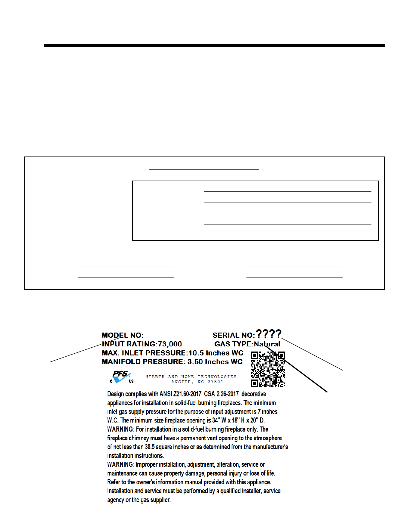
Listing Label Information/Location
Serial Number
Type of Gas
The model information regarding your specific gas log set can be
found on the rating plate usually located in the control area
of the gas log set.
Model Number
Congratulations and thank you for selecting a Hearth &
Home Technologies vented
gas log set, an elegant and
clean alternative to wood burning fireplaces. The gas log
set you have selected is designed to provide the utmost
in safety, efficiency, and style.
As the owner of a new vented gas log set, you’ll want to
read and carefully follow all of the instructions contained in
this owner’s manual. Pay special attention to all cautions
and warnings.
This owner’s manual should be retained for future
reference. We suggest that you keep it with your other
important documents and product manuals.
The information contained in this owner’s manual, unless
noted otherwise, applies to all models and gas control
systems noted on the cover page.
Your new vented gas log set will give you years of durable
use and trouble-free enjoyment. Welcome to the Hearth
& Home family.
Dealer Name:
Address:
Phone Number:
Email:
Dealer: Fill in your name, ad-
dress, phone number and email
information in the space pro-
vided.
Local Dealer Information
Appliance Information:
Brand: Model Name:
Serial Number: Date Installed:
UNLESS OTHERWISE SPECIFIED DIMS ARE INCHES [mm] & TOLERANCES ARE: (2) PLACE DEC: ± 0.03 (3) PLACE DEC: ± 0.005 ANGLE: ± 2° FRACTION: ± 1/16
OUTSIDE MATERIAL NORMAL DIM & INSIDE MATERIAL OUTSIDE APEX INSIDE APEX - DIMS ENCLOSED BY AN OVAL ARE CRITICAL DIMENSIONS
PART NAME:
DRAWN BY:
SCALE:
MATERIAL:
SHEET:
PART NUMBER: REV:
THIS PRINT IS CHECKED AND CONTROLLED BY THE ENGINEERING
DEPARTMENTS OF HEARTH & HOME TECHNOLOGIES INC.
CONFIDENTIAL PROPERTY OF HEARTH & HOME TECHNOLOGIES INC.
REV
REVISIONS
ECO #
DATE
BY
PART# 4100-635 4100-637 4100-636 4100-638
MODEL RB-18/24NI RB-30NI RB-18/24PI RB-30PI
GAS TYPE NATURAL NATURAL PROPANE PROPANE
RATE 50,000 btu/hr (14.65 kW) 65,000 btu/hr (19.045 kW) 50,000 btu/hr (14.65 kW) 65,000 btu/hr (19.045 kW)
ORIFICE .144 in. (3.7 mm) .161 in. (4.1 mm) .086 in. (2.2 mm) .098 in. (2.5 mm)
MANIFOLD 3.5 in. wc (.87 kPa) 3.5 in. wc (.87 kPa) 10.0 in. wc (2.49 kPa) 10.0 in. wc (2.49 kPa)
INLET MIN 5.0 in. wc (1.24 kPa) 5.0 in. wc (1.24 kPa) 11.0 in. wc (2.74 kPa) 11.0 in. wc (2.74 kPa)
INLET MAX 10.0 in. wc (2.49 kPa) 10.0 in. wc (2.49 kPa) 13.0 in. wc (3.23 kPa) 13.0 in. wc (3.23 kPa)
FRONT 28.0" (711 mm) 34.0" (864 mm) 28.0" (711 mm) 34.0" (864 mm)
REAR 18.50" (470 mm) 24.50" (622 mm) 18.50" (470 mm) 24.50" (622 mm)
1 OF 1 4660-990 A
A RELEASED P16427 FOX03/20/24
FOX
NTS 14D3212
RATING LABEL
11
Welcome
A. Congratulations
Hearth & Home Technologies • Stadium Installation Manual • 4004-900 Rev. B • 03/25

5
Hearth & Home Technologies LLC
LIMITED WARRANTY
Hearth & Home Technologies LLC (“HHT”) extends the following warranty for HHT gas, wood, pellet and electric hearth appliances
(each a “Product” and collecvely, the “Product(s)”) and certain component parts set forth in the table below (“Component Part(s)”)
that are purchased from a HHT authorized dealer or distributor.
WARRANTY COVERAGE:
HHT warrants that the Products and their Component Parts will be free from defects in materials and workmanship for the applicable
period of Warranty coverage set forth in the table below (“Warranty Period”). If a Product or Component Parts are found to be
defecve in materials or workmanship during the applicable Warranty Period, HHT will, at our discreon, repair the applicable
Component Part(s), replace the applicable Component Part(s), or refund the purchase price of the applicable Product(s). The maximum
amount recoverable under this Warranty is limited to the purchase price of the Product. This Warranty is transferable from the original
purchaser to subsequent owners, but the Warranty Period will not be extended in duraon or expanded in coverage for any such
transfer. This Warranty is subject to condions, exclusions, and limitaons as described below.
WARRANTY PERIOD:
Warranty coverage begins at the date of installaon. In the case of new home construcons, Warranty coverage begins six months aer
invoice of the nal sale of the Product(s) by an independent, authorized HHT dealer or distributor. However, the Warranty coverage
shall commence no later than 24 months following the date of Product shipment from HHT, regardless of the installaon or purchase
date.
Page 1 of 2
4021-645N 12/23
Component
Parts
Labor Gas Pellet Wood Electric Component Parts Covered by this Warranty
X
All parts except as covered by Warranty Conditions, Warranty Exclusions, and Warranty
Limitations listed
XX
Glass, Electrical components limited to heating element/igniters, Top feed auger assembly,
Blowers, Junction Box, Remotes/Wall switches, linear actuator, power cord, vacuum switch,
snap disc, wire harnesses and thermocouple
X
Electrical components limited to modules, remotes/wall switches, valves, pilots, blowers,
junction boxes, wire harnesses, transformers and lights (excluding light bulbs)
XX
Cement Refractory Panels, Glass Liner Panels
X
Firepots, burnpots, Harman mechanical feeders
XX
Catalysts, Vented and Vent Free burners and logs
10 years 1 year
X
Burners, logs and metal/fiber refractory components of HHT manufactured fireplaces or stoves,
venting due to poor workmanship
10 years
3 years
XX
Castings, Medallions & Baffles, FlexBurn® System (engine, inner cover, access cover and
fireback), Firebox and heat exchanger, HHT Chimney & Terminations, Manifolds
20 years 3 years X Firebox and heat exchanger
1 Year
None
XXXX
All purchased replacement parts and optional accessories
3 years
5 years
All purchased replacement parts and optional accessories
2 Years
Warranty Period HHT Manufactured Appliances and Venting
All parts including handles, external enameled components and other material except as
covered by Warranty Conditions, Warranty Exclusions, and Warranty Limitations listed
1 Year XXX
B. Limited Lifetime Warranty
Hearth & Home Technologies • Stadium Installation Manual • 4004-900 Rev. B • 03/25

6
B. Limited Lifetime Warranty (Continued)
WARRANTY CONDITIONS:
• Because HHT cannot control the quality of any Products sold by unauthorized sellers, this Warranty only covers Products that are
purchased through an HHT authorized dealer or distributor unless otherwise prohibited by law; a list of HHT authorized dealers
is available on the HHT branded websites.
• This Warranty is only valid while the applicable Product remains at the site of original installaon.
• This Warranty is only valid in the country in which the HHT authorized dealer or distributor that sold the applicable Product is
authorized to sell applicable Product.
• Contact your installing distributor or dealer for Warranty service. If the installing dealer or distributor is unable to provide
necessary parts, contact the nearest HHT authorized dealer or supplier. Addional service fees may apply if you are seeking
Warranty service from a dealer other than the dealer from whom you originally purchased the applicable Product.
• No HHT consumer should bear cost of warranty service or costs incurred while servicing warranty claims (i.e., travel, gas, or
mileage) when the service is performed within the terms of this Warranty. Check with your dealer or distributor in advance for
any costs to you when arranging a warranty call. Travel and shipping charges for parts are not covered by this Warranty.
WARRANTY EXCLUSIONS:
This Warranty does not cover the following:
• Changes in surface nishes as a result of normal use. As a heang appliance, some changes in color of interior and exterior surface
nishes may occur. This is not a aw and is not covered under the Warranty.
• Damage to printed, plated, or enameled surfaces caused by ngerprints, accidents, misuse, scratches, melted items or other
external sources and residues le on the plated surfaces from the use of abrasive cleaners or polishes.
• Repair or replacement of parts that are subject to normal wear and tear during the Warranty Period are not covered. These parts
include: paint, wood and pellet gaskets, rebricks, wood grates, ame guides, baeries and the discoloraon of glass.
• Minor expansion, contracon, or movement of certain parts causing noise. These condions are normal and complaints related to
this noise are not covered by this Warranty.
• Damages resulng from: (1) failure to install, operate, or maintain the applicable Product in accordance with the installaon
instrucons, operang instrucons, and lisng agent idencaon label furnished with the applicable Product; (2) failure to
install the applicable Product in accordance with local building codes; (3) shipping or improper handling; (4) improper operaon,
abuse, misuse, connued operaon with damaged, corroded or failed components, accident, or improperly/incorrectly performed
repairs; (5) environmental condions, inadequate venlaon, negave pressure, or draing caused by ghtly sealed construcons,
insucient make-up air supply, or handling devices such as exhaust fans or forced air furnaces or other such causes; (6) use of fuels
other than those specied in the operaon instrucons; (7) installaon or use of components not supplied with the applicable
Product or any other components not expressly authorized and approved by HHT; (8) modicaon of the appliance not expressly
authorized and approved by HHT in wring; and/or (9) interrupons or uctuaons of electrical power supply to the applicable
Product.
• Non-HHT venng components, hearth connecons or other accessories used in conjuncon with the applicable Product.
• Any part of a pre-exisng replace system in which an insert or a decorave gas applicable Product is installed.
• HHT’s obligaon under this Warranty does not extend to the Product’s capability to heat the desired space. Informaon is provided
to assist the consumer and the dealer in selecng the proper Product for the applicaon. Consideraon must be given to the
Product locaon and conguraon, environmental condions, insulaon and air ghtness of the structure.
This warranty is void if:
• The applicable Product has been over-red, operated in atmospheres contaminated by chlorine, uorine, or other damaging
chemicals. Over-ring can be idened by, but not limited to, warped plates or tubes, deformaon/warping of interior cast iron
structure or components, rust colored cast iron, bubbling, cracking and discoloraon of steel or enamel nishes.
• The applicable Product is subjected to prolonged periods of dampness or condensaon.
• There is any damage to the applicable Product due to water or weather damage which is the result of, but not limited to, improper
chimney or venng installaon.
LIMITATIONS OF REMEDIES AND LIABILITY:
• EXCEPT TO THE EXTENT PROVIDED BY LAW, HHT MAKES NO EXPRESS WARRANTIES OTHER THAN THE WARRANTY SPECIFIED
HEREIN. The owner’s exclusive remedy and HHT’s sole obligaon under this Warranty or in contract, tort or otherwise, shall
be limited to, at HHT’s sole opon, replacement of the Component Part(s), repair of the Component Part(s), or refund of the
original purchase price of the applicable Product(s). In no event will HHT be liable for any incidental or consequenal damages
caused by defects in the applicable Product. Some States do not allow the exclusion or limitaon of incidental or consequenal
damages, so the above limitaon or exclusion may not apply to you. This Warranty gives you specic legal rights and you may
also have other rights which vary from State to State. THE DURATION OF ANY IMPLIED WARRANTY IS LIMITED TO DURATION OF
THE EXPRESSED WARRANTY SPECIFIED ABOVE FOR THE APPLICABLE PRODUCT. Some States do not allow limitaons on how long
an implied warranty lasts, so the above limitaon may not apply to you.
Page 2 of 2
4021-645N 12/23
7
A. Appliance Certification
NOT INTENDED FOR USE AS A PRIMARY HEAT
SOURCE. This appliance is tested and approved as
either supplemental room heater or as a decorative ap-
pliance. It should not be factored as primary heat in
residential heating calculations.
This product is listed to ANSI standards for "Vented Gas
Log Sets” and applicable sections of "Gas Burning Heat-
ing Appliances for Manufactured Homes" and "Gas Fired
Appliances for Use at High Altitude."
NOTICE: This installation must conform with local codes.
In the absence of local codes you must comply with the
National Fuel Gas Code, ANSI Z223.1-latest edition in
the U.S.A.
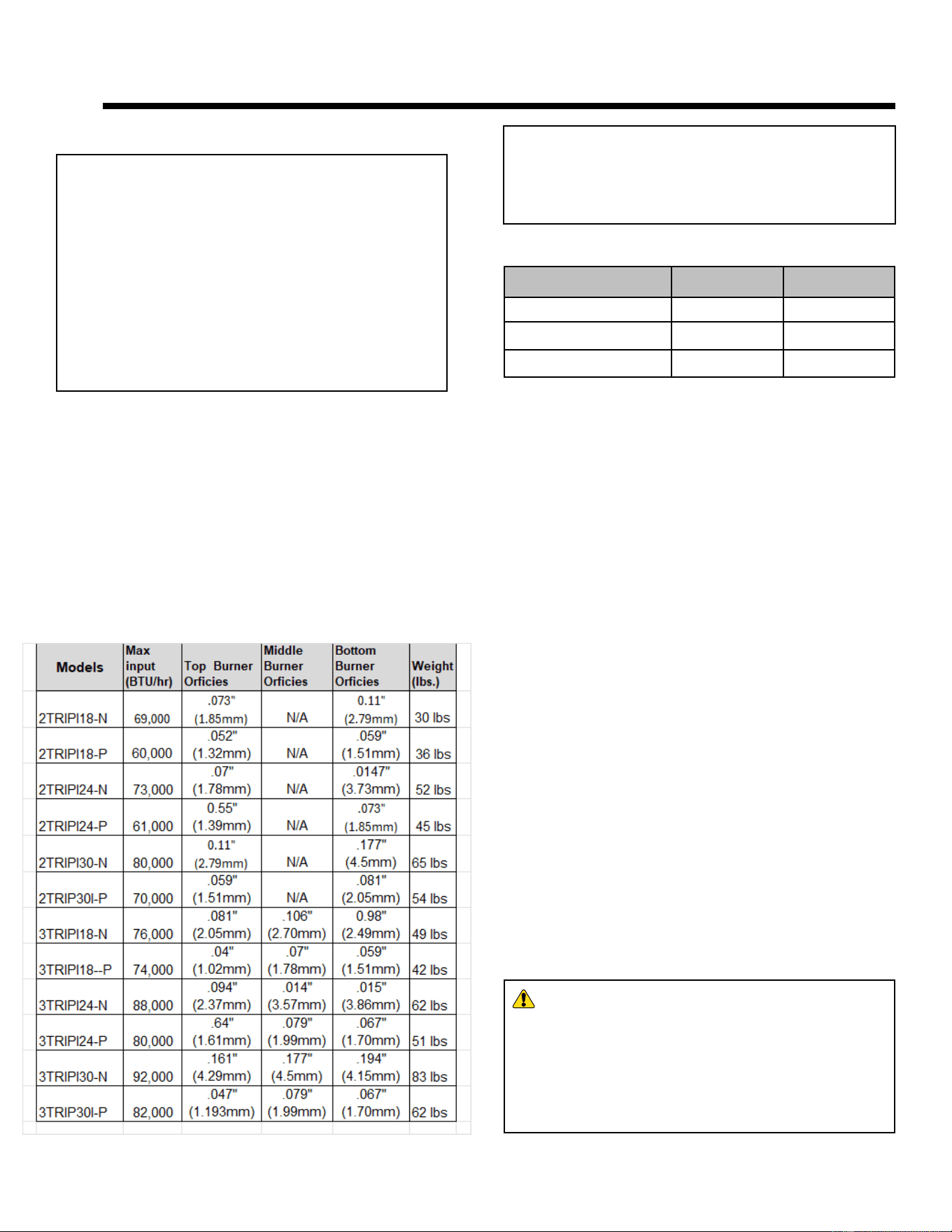
B. BTU Specifications and Weight
NATURAL GAS: An external regulator is required to
reduce supply pressure to a maximum of 10.0” wc.
PROPANE/LP: An external regulator is required to re-
duce supply pressure to a maximum of 13.0” wc.
D. High Altitude Installations
NOTICE: If the heating value of the gas has been reduced,
these rules do not apply. Check with your local gas utility
or authorities having jurisdiction.
When installing above 2000 feet elevation:
• In the USA: Reduce input rate 4% for each 1000 feet
above 2000 feet.
•
•
In CANADA: Input ratings are certified without a
reduction of input rate for elevations up to 4500
feet (1370 m) above sea level. Please consult
provincial and/ or local authorities having jurisdiction
for installations atelevations above 4500 feet (1370
m).Check with your local gas utility to determine
proper orifice size.
Check with your local gas utility to determine proper
orifice size
C. Gas Pressures
2TR-IPI-R18-N; 2TR-IPI-R18-P
2TR-IPI-R24-N; 2TR-IPI-R24-P
2TR-IPI-R30-N; 2TR-IPI-R30-P
3TR-IPI-R18-N; 3TR-IPI-R18-P
3TR-IPI-R24-N; 3TR-IPI-R24-P
3TR-IPI-R30-N; 3TR-IPI-R30-P
PFS
Vented Gas Log Set
ANSI Z21.60-2017 • CSA 2.26-
2017 Decorative gas appliances
for installation in solid-fuel burning
fireplaces
E. Fuel
This appliance must not be used to burn solid fuel.
F. Glass Doors
This appliance must NOT be operated with glass doors in
the closed position.
G. California
WARNING!
This product and the fuels used to
operate this product (liquid propane or natural gas), and
the products of combustion of such fuels, can expose
you to chemicals including benzene, which is known to
the State of California to cause cancer and reproductive
harm. For more information go to: www.P65Warnings.
ca.gov.
Natural Propane (LP)
Inlet Minimum 5.0” wc 11.0” wc
Inlet Maximum 10.0” wc 13.0” wc
Manifold Pressure 3.5” wc 10.0” wc
MODEL(S):
LABORATORY:
TYPE:
STANDARD:
22
Product Specific and Important Safety Information
Hearth & Home Technologies • Stadium Installation Manual • 4004-900 Rev. B • 03/25

8
For all side wall horizontally vented gas fueled equipment
installed in every dwelling, building or structure used in
whole or in part for residential purposes, including those
owned or operated by the Commonwealth and where the
side wall exhaust vent termination is less than seven (7)
feet above finished grade in the area of the venting, in-
cluding but not limited to decks and porches, the following
requirements shall be satisfied:
Installation of Carbon Monoxide Detectors
At the time of installation of the side wall horizontal vented
gas fueled equipment, the installing plumber or gas fitter
shall observe that a hard wired carbon monoxide detector
with an alarm and battery back-up is installed on the floor
level where the gas equipment is to be installed. In addi-
tion, the installing plumber or gas fitter shall observe that
a battery operated or hard wired carbon monoxide detec-
tor with an alarm is installed on each additional level of
the dwelling, building or structure served by the side wall
horizontal vented gas fueled equipment. It shall be the
responsibility of the property owner to secure the services
of qualified licensed professionals for the installation of
hard wired carbon monoxide detectors.
In the event that the side wall horizontally vented gas fu-
eled equipment is installed in a crawl space or an attic,
the hard wired carbon monoxide detector with alarm and
battery back-up may be installed on the next adjacent
floor level.
In the event that the requirements of this subdivision can
not be met at the time of completion of installation, the
owner shall have a period of thirty (30) days to comply
with the above requirements; provided, however, that dur-
ing said thirty (30) day period, a battery operated carbon
monoxide detector with an alarm shall be installed.
Approved Carbon Monoxide Detectors
Each carbon monoxide detector as required in accor-
dance with the above provisions shall comply with NFPA
720 and be ANSI/UL 2034 listed and IAS certified.
Signage
A metal or plastic identification plate shall be permanent-
ly mounted to the exterior of the building at a minimum
height of eight (8) feet above grade directly in line with the
exhaust vent terminal for the horizontally vented gas fu-
eled heating appliance or equipment. The sign shall read,
in print size no less than one-half (1/2) in. in size, “GAS
VENT DIRECTLY BELOW. KEEP CLEAR OF ALL OB-
STRUCTIONS”.
Inspection
The state or local gas inspector of the side wall horizon-
tally vented gas fueled equipment shall not approve the
installation unless, upon inspection, the inspector ob-
serves carbon monoxide detectors and signage installed
in accordance with the provisions of 248 CMR 5.08(2)(a)1
through 4.
Exemptions
The following equipment is exempt from 248 CMR 5.08(2)
(a)1 through 4:
• The equipment listed in Chapter 10 entitled “Equipment
Not Required To Be Vented” in the most current edition
of NFPA 54 as adopted by the Board; and
• Product Approved side wall horizontally vented gas fu-
eled equipment installed in a room or structure separate
from the dwelling, building or structure used in whole or
in part for residential purposes.
MANUFACTURER REQUIREMENTS
Gas Equipment Venting System Provided
When the manufacturer of Product Approved side wall
horizontally vented gas equipment provides a venting
system design or venting system components with the
equipment, the instructions provided by the manufacturer
for installation of the equipment and the venting system
shall include:
• Detailed instructions for the installation of the venting
system design or the venting system components; and
• A complete parts list for the venting system design or
venting system.
Gas Equipment Venting System NOT Provided
When the manufacturer of a Product Approved side wall
horizontally vented gas fueled equipment does not pro-
vide the parts for venting the flue gases, but identifies
“special venting systems”, the following requirements
shall be satisfied by the manufacturer:
• The referenced “special venting system” instructions
shall be included with the appliance or equipment in-
stallation instructions; and
• The “special venting systems” shall be Product Ap-
proved by the Board, and the instructions for that sys-
tem shall include a parts list and detailed installation
instructions.
A copy of all installation instructions for all Product Ap-
proved side wall horizontally vented gas fueled equip-
ment, all venting instructions, all parts lists for venting
instructions, and/or all venting design instructions shall
remain with the appliance or equipment at the completion
of the installation.
See Gas Connection section for additional Common-
wealth of Massachusetts requirements.
H. Requirements for the Commonwealth of
Massachusetts
Hearth & Home Technologies • Stadium Installation Manual • 4004-900 Rev. B • 03/25
9
DANGER
33
Important Safety and Operating Information
Clear Space
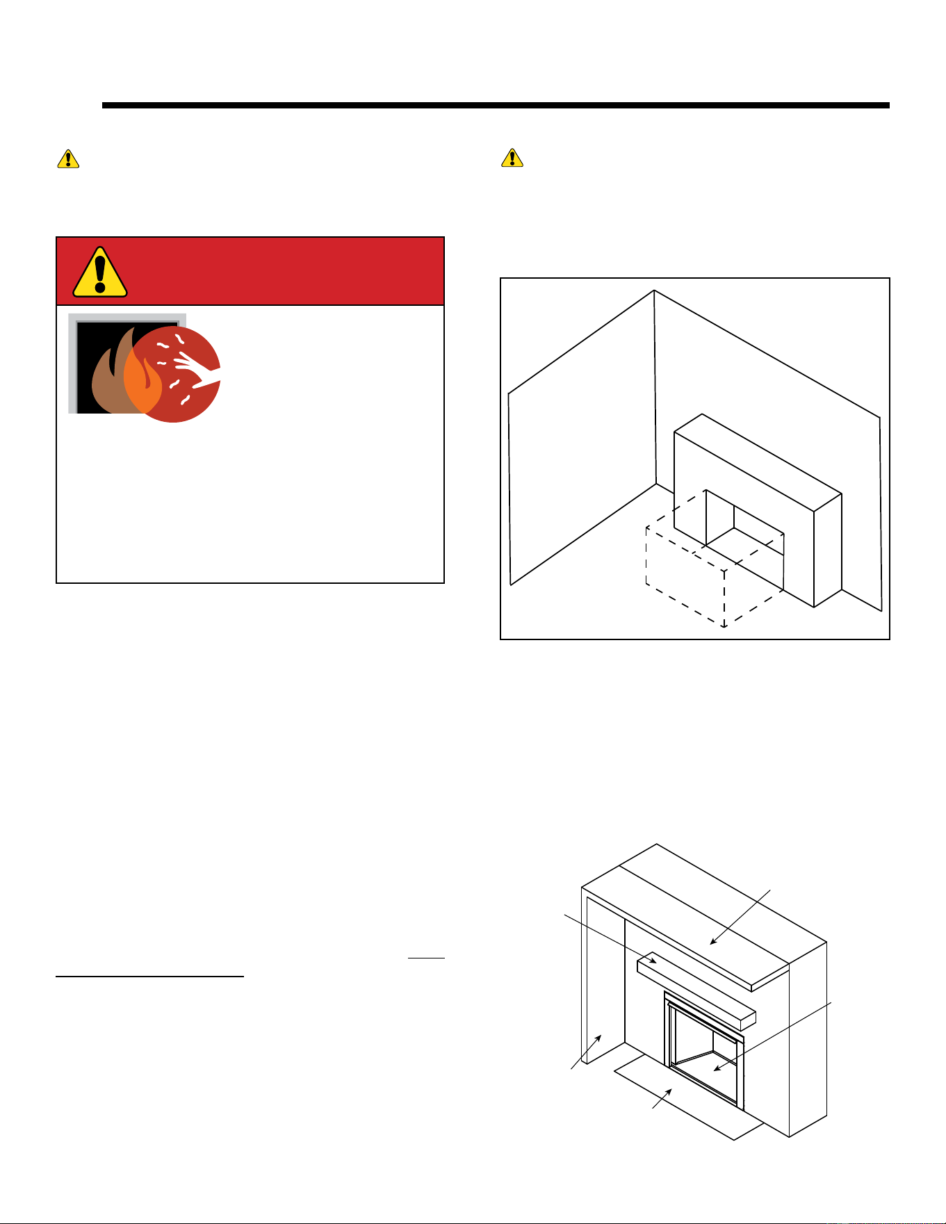
WARNING! DO NOT place combustible objects in
front of the appliance. High temperatures may start a re.
See Figure 3.1.
Avoid placing candles, electronics and other heat-sensitive
objects on mantel or hearth. Heat may damage these
objects.
Over Firing
The appliance is considered to be over firing if the flames
are contacting the top of the firebox. Call a qualified service
technician to service the appliance.
CLEAR SPACE
3 FT. IN FRONT
OF FIREPLACE
WARNING! DO NOT operate appliance before
reading and understanding operating instructions.
Failure to operate appliance according to operating in-
structions could cause re or injury.
Young children should be carefully supervised when they
are in the same room as the appliance. Toddlers, young
children and others may be susceptible to accidental
contact burns.
• A physical barrier is recommended if there are at risk
individuals in the house.
• To restrict access to a appliance, install an adjustable
safety gate to keep toddlers, young children and other
at risk individuals out of the room and away from hot
surfaces.
• Install a switch lock or a wall/remote control with child
protection lockout feature.
• Keep remote controls out of reach of children.
• Never leave children alone near a hot appliance,
whether operating or cooling down.
• Teach children to NEVER touch the appliance.
• Consider not using the appliance when children will
be present.
Contact your dealer for more information, or visit: www.
hpba.org/safety-information.
To prevent unintended operation when not using your ap-
pliance for an extended period of time (summer months,
vacations, trips, etc):
• Remove batteries from remote controls.
• Turn off gas shutoff valve.
• Keep children away.
• CAREFULLY SUPERVISE children in same room as
appliance.
• Alert children and adults to hazards of high temperatures.
High temperatures may ignite clothing or other
flammable materials.
• Clothing, furniture, draperies, and other flammable
materials must not be placed on or near the appliance.
A. Appliance Safety
Figure 3.1 Clear Space Requirements
Ceiling or
Overhang
Additional
Structure or
Sidewall
Mantel
Hearth
Firebox
Figure 3.2 references the general operating parts of a
typical installation.
B. General Operating Parts
Figure 3.2 General Operating Parts
Hearth & Home Technologies • Stadium Installation Manual • 4004-900 Rev. B • 03/25

10
Installation MUST comply with local, regional, state and
national codes and regulations. Consult insurance carrier,
local building inspector, fire officials or authorities having
jurisdiction over restrictions, installation inspection and
permits.
Before installing, determine the following:
• Where burner assembly and log set are to be in-
stalled.
• Gas supply piping.
• Whether optional accessories, devices such as a wall
switch or remote control are desired.
• Approved wood burning or masonry fireplace.
Improper installation, adjustment, alteration, service or
maintenance can cause injury or property damage. For
assistance or additional information, consult a qualified
service technician, service agency or your dealer.
Before beginning the installation be sure that the following
tools and building supplies are available.
• Tape measure
• Gloves
• Voltmeter
• Manometer
• Phillips screwdriver
• Safety glasses
• Flat blade screwdriver
• Non-corrosive leak check solution
• Drill and bits
• External regulator (for propane/LP only & 1/2 psi
Natural gas system)
• Piping which complies with local codes
• Pipe sealant approved for use with propane/LP
(Resistant to sulfur compounds)
WARNING! Risk of Fire, Explosion or Electric
Shock! DO NOT use this appliance if any part has been
under water. Call a qualied service technician to inspect
the appliance and to replace any part of the control sys-
tem and/or gas control which has been under water.
• Manual shutoff valve
• Sediment trap
• Tee joint
• Pipe wrench
• 3/4” & 7/16” wrench
Gloves are recommended when handling
refractory and logs to prevent skin irritation
from loose fibers. Logs are fragile; handle with
care.
Verify contents to ensure you have received all parts.
You should have the following:
• Log Set (Sold Seperately)
• Vented Gas Log Burner / Grate Assembly
• RCB Remote Control
• Lava Rock
• Rock Wool
• Sand (NG Only)
• Vermiculite
• Installation Instructions
• Flex Line & Pipe Fittings
• Damper Clamp
Installation and service of this appliance should be performed by
qualified personnel. Hearth & Home Technologies recommends
HHT Factory Trained or NFI certified professionals.
CAUTION
• Carefully remove the applaince and components from
the packaging.
• Attached to the appliance are tags identifying the
manufacturer, serial number, model number. Including
log set size, BTU/hr ratings and gas type.
• Review the attached tags before proceeding. Ensure
that all minimum fireplace dimension requirements are
achieved using Figure 4.1.
• Ensure the gas type provided in the fireplace coincide
with the gas type marked on the tag.
• Logs are packaged and sold separately.
• Report to your dealer any parts damaged in shipment.
• Read all of the instructions before starting the instal-
lation. Follow these instructions carefully during the
installation process to ensure maximum safety and
benefit.
Hearth & Home Technologies disclaims any respon-
sibility for, and the warranty will be voided by, the fol-
lowing actions:
• Installation and use of any damaged appliance.
• Modification of the appliance.
• Installation other than as instructed by Hearth &
Home Technologies.
• Installation and/or use of any component part not
approved by Hearth & Home Technologies.
Any such action may cause a fire hazard.
44
Getting Started
A. Design and Installation Considerations
B. Tools and Supplies Needed
C. Inspect Appliance and Components
WARNING! Risk of Fire or Explosion! Damaged
parts could impair safe operation. DO NOT install damaged,
incomplete or substitute components. Keep appliance dry.
D. Check Parts
Hearth & Home Technologies • Stadium Installation Manual • 4004-900 Rev. B • 03/25
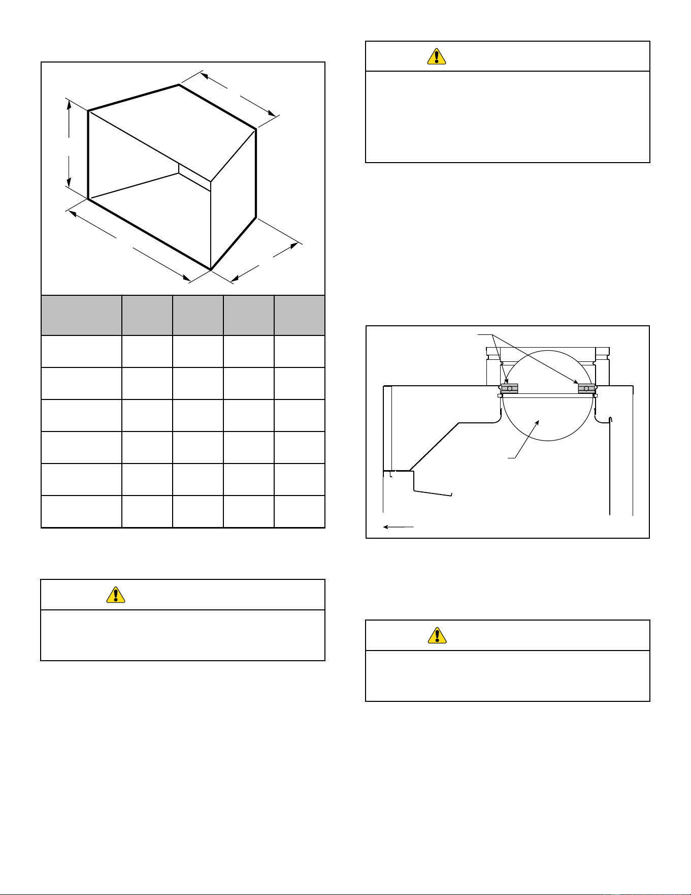
11
A
C
D
B
F. Installation Information
Figure 4.1 Minimum Hearth Dimensions
E. Minimum Hearth Dimensions
Do not install the applaince:
• Where curtains, furniture, clothing, or other
flammable objects are less than 36" from the
front of the heater.
• In high traffic areas.
• In windy or drafty areas.
BEFORE INSTALLING THE APPLIANCE:
• Turn off gas supply to masonry fireplace or manufac-
tured wood burning firebox.
• Have the fireplace floor and chimney professionally
cleaned to remove ash, soot, creosote or other ob-
structions. Have this cleaning performed annually af-
ter installation.
• Seal any fresh air vents or ash clean-out doors lo-
cated on floor or wall of fireplace. If not, drafting may
cause pilot outage or sooting. Use a heat-resistant
sealant.
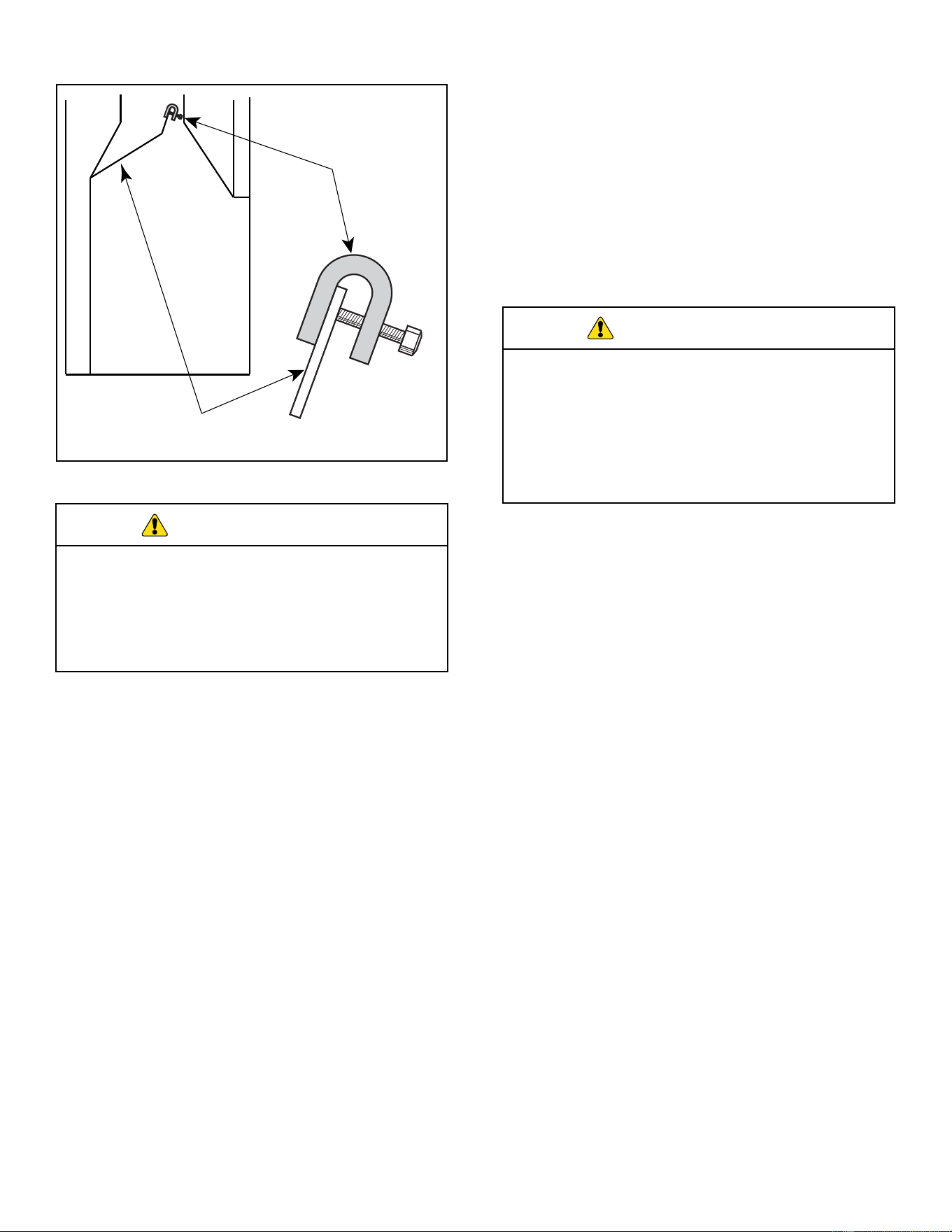
Damper Stop Installation
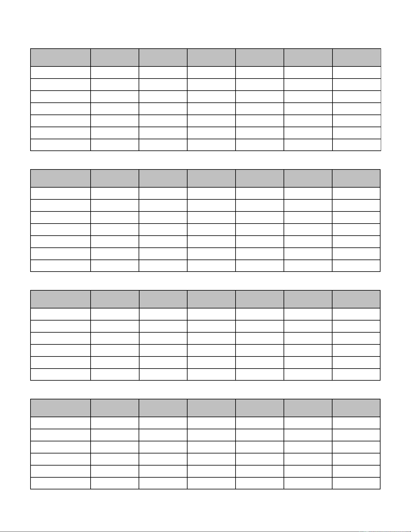
A damper stop is provided with this appliance. The damp-
er stop MUST be installed to prevent full closure of the
fireplace damper blade and provide a minimum flue open-
ing. See Table 4.1.
WARNING
WARNING
Note: Should the stop not fit, or provide the required per-
manent opening from the table have the damper blade cut
to provide minimum permanent opening or a permanent
stop installed.
WARNING
Improper installation or use of the appliance can
cause serious injury or death from fire, burns,
explosion or carbon monoxide poisoning.
Recommended
Damper Stop
Location
Damper
Blade
Front of Fireplace
Figure 4.2 Factory Built Fireplace Example
Factory Built Fireplace: Position damper stop on the top
half of the damper blade, slide stop towards the center
of the damper blade to create an interferance with the
bead on the flue collar and tighten bolt. Either side of the
damper blade is acceptable. See Figure 4.2.
Models A B C D
2TR-IPI-R18-N
2TR-IPI-R18-P
27.00”
(686 mm)
16.00”
(406 mm)
19.00”
(483 mm)
18.00”
(457 mm)
2TR-IPI-R24-N
2TR-IPI-R24-P
34.00”
(864 mm)
20.00”
(508 mm)
22.00”
(559 mm)
18.00”
(457 mm)
2TR-IPI-R30-N
2TR-IPI-R30-P
40.00”
(1016 mm)
20.00”
(508 mm)
29.00”
(737 mm)
18.00”
(457 mm)
3TR-IPI-R18-N
3TR-IPI-R18-P
32.00”
(813 mm)
23.00”
(584 mm)
21.00”
(533 mm)
22.00”
(559 mm)
3TR-IPI-R24-N
3TR-IPI-R24-P
34.00”
(864 mm)
23.00”
(584 mm)
22.00”
(559 mm)
22.00”
(559 mm)
3TR-IPI-R30-N
3TR-IPI-R30-P
40.00”
(1016 mm)
23.00”
(584 mm)
29.00”
(737 mm)
22.00”
(559 mm)
Note: Use manufacturer’s installation and clearance re-
quirements as defined in their manual.
This appliance is for installation only in a solid-fuel
burning masonry or UL127 factory-built fireplace.
It has been design certified for these installations.
Hearth & Home Technologies • Stadium Installation Manual • 4004-900 Rev. B • 03/25
12
For Massachusetts Residents Only
Installation of this vented gas log set in the Common-
wealth of Massachusetts requires the damper be perma-
nently removed or welded in the fully open position. In
addition, a naturally vented gas log may not be installed
in a bedroom or bathroom in the Commonwealth of Mas-
sachusetts.
WARNING
The fireplace and gas logs function as a system. If
the fireplace is spilling into the room (check with
a match or smoke stick), reposition the damper
clamp until a positive draft is obtained, by opening
the damper. If negative pressure in the home pre-
vents having a positive draft contact your dealer.
FP2727
damper
Damper
Stop
Damper
Blade
Figure 4.3 Masonary Fireplace Example
Damper Stop Installation (cont.)
This appliance shall not be installed in a confined space or
unusually tight construction unless provisions are provided
for adequate combustion and ventilation air.
The National Fuel Gas Code, (ANSI Z223.1/NFPA54),
defines a confined space as a space whose volume is less
than 50 cubic feet per 1,000 BTU per hour (4.8m
3
per kw)
of the aggregate input rating of all appliances installed in
that space. Rooms communicating directly with the space
in which the appliances are installed, through openings not
furnished with doors, are considered a part of a confined
space.
If the area in which the appliance may be
operated does not meet the required volume
for indoor combustion air, combustion and
ventilation air shall be provided by one of the
methods described in the National Fuel Gas
Code, ANSI Z223.1/NFPA 54, the International
Fuel Gas Code or applicable local codes.
WARNING
Negative pressure results from the imbalance of air avail-
able for the fireplace to operate properly. Possible causes
for this imbalance include:
• Exhaust fans (kitchen, bath, etc.)
• Range hoods
• Combustion air requirements for furnaces, water heat-
ers and other combustion appliances
• Clothes dryers
• Location of return-air vents to furnace or air condition-
ing
• Imbalances of the HVAC air handling system
• Upper level air leaks: recessed lighting, attic hatch
opening, duct leaks.
G. Adequate Combustion Ventilation Air
H. Negative Pressure
Hearth & Home Technologies • Stadium Installation Manual • 4004-900 Rev. B • 03/25
13
Chimney Height 2TR-IPI-R18-N 2TR-IPI-R18-P 2TR-IPI-R24-N 2TR-IPI-R24-P 2TR-IPI-R30-N 2TR-IPI-R30-P
10 ft
28.3 22.1 Not Allowed 44.2 Not Allowed 44.2
15 ft
21.2 17.3 38.5 32.2 38.5 32.2
20 ft
18.1 14.5 31.2 26.4 31.2 26.4
25 ft
15.9 12.6 27.3 22.9 27.3 22.9
30 ft
14.5 11.3 24.6 20.4 24.6 20.4
35 ft
13.2 10.8 22.1 18.9 22.1 18.9
40 ft
12.6 10.2 20.4 18.1 20.4 18.1
Chimney Height 3TR-IPI-R18-N 3TR-IPI-R18-P 3TR-IPI-R24-N 3TR-IPI-R24-P 3TR-IPI-R30-N 3TR-IPI-R30-P
10 ft
Not Allowed Not Allowed Not Allowed Not Allowed Not Allowed Not Allowed
15 ft
45.4 38.5 45.4 38.5 Not Allowed 45.4
20 ft
37.4 31.2 37.4 31.2 43.0 37.4
25 ft
31.2 27.3 31.2 27.3 36.3 31.2
30 ft
28.3 24.6 28.3 24.6 33.2 28.3
35 ft
25.5 22.1 25.5 22.1 30.2 25.5
40 ft
23.8 20.4 23.8 20.4 27.3 23.8
Chimney Height 2TR-IPI-R18-N 2TR-IPI-R18-P 2TR-IPI-R24-N 2TR-IPI-R24-P 2TR-IPI-R30-N 2TR-IPI-R30-P
6 ft
41.7 33.8 64.0 56.6 64.0 56.6
8 ft
38.7 31.2 59.7 52.4 59.7 52.4
10 ft
35.2 28.7 54.3 48.2 54.3 48.2
15 ft
32.0 26.1 48.8 43.2 48.8 43.2
20 ft
28.8 23.7 44.4 39.8 44.4 39.8
30 ft
26.5 21.6 40.3 35.9 40.3 35.9
Chimney Height 3TR-IPI-R18-N 3TR-IPI-R18-P 3TR-IPI-R24-N 3TR-IPI-R24-P 3TR-IPI-R30-N 3TR-IPI-R30-P
6 ft
71.4 64.0 71.4 64.0 78.8 71.4
8 ft
66.9 59.7 66.9 59.7 74.1 66.9
10 ft
60.2 54.3 60.2 54.3 66.1 60.2
15 ft
54.1 48.8 54.1 48.8 59 54.1
20 ft
49.1 44.4 49.1 44.4 53.8 49.1
30 ft
44.5 40.3 44.5 40.3 48.6 44.5
Free opening area of chimney damper for venting combustion products (factory-built fireplaces)
Free opening area of chimney damper for venting combustion products (factory-built fireplaces)
Free opening area of chimney damper for venting combustion products (masonary-built fireplaces)
Free opening area of chimney damper for venting combustion products (masonary-built fireplaces)
Table 4.1
Minimum Flue Opening
Hearth & Home Technologies • Stadium Installation Manual • 4004-900 Rev. B • 03/25
14
55
Gas Information
Use new black iron or steel pipe. Internally tinned
copper or copper tubing can be used per National
Fuel Code, providing gas meets hydrogen sulfide
limits, and where permitted by local codes. Gas
piping system must be sized to provide minimum
inlet pressure (Listed on Data Plate) at the maximum
flow rate (BTU/hr). Undue pressure loss will occur if
the pipe is too small.
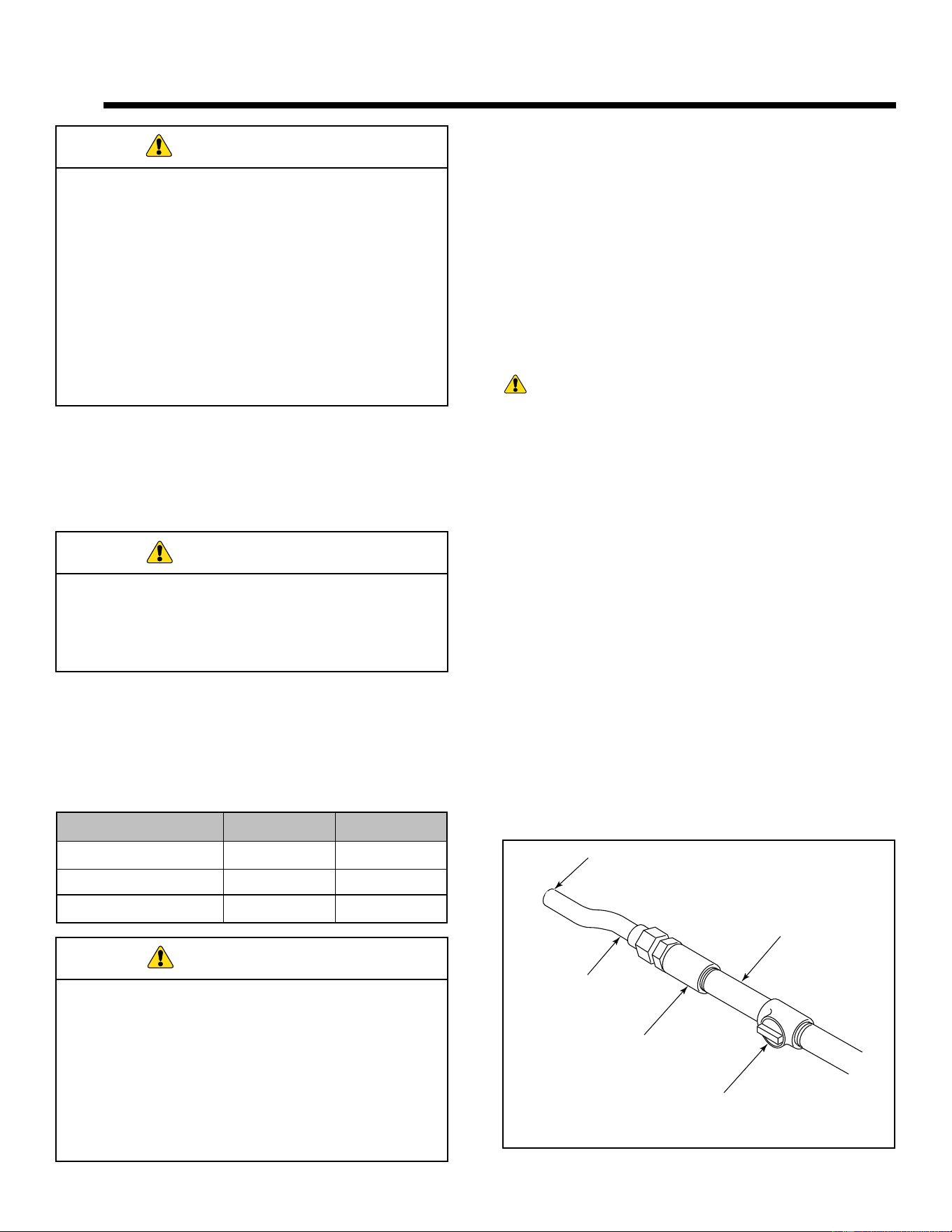
A manual shutoff valve must be installed upstream
of the appliance. Union tee and plugged 1/8” NPT
pressure tapping point should be installed upstream
of the appliance.
A 3/8 in. flared fitting has been installed on the gas valve
inlet at the factory. Ensure fittings are of the appropriate
size and type on the gas line connection. If the tubing has
to be cut to length be sure to use the proper cutting and
flaring tool. Also, be careful not to crimp the tubing while
bending. If the tubing becomes crimped, do not use for
installation.
IMPORTANT: When tightening up the joint to the valve,
hold the valve securely to prevent movement.
Test all gas joints from the gas meter to the appliance
valve for leaks using a gas analyzer or soap and water
solution after completing connection. DO NOT USE AN
OPEN FLAME. Check the gas pressure with the appli-
ance burning.
Fire Risk!
Explosion Hazard!
High pressure will damage valve!
• Disconnect gas supply piping BEFORE pres-
sure testing gas line at test pressures above
1/2 psig.
• Close the manual shutoff valve BEFORE pres-
sure testing gas line at test pressures equal to
or less than 1/2 psig.
Manual
Shutoff Valve
Coupling
To Control Valve
Flexible
Connector
Gas Supply
Line
The gas supply must be the same as stated on the appli-
ance rating plate. If the gas supply is different, DO NOT
INSTALL THE APPLIANCE. Contact your dealer for the
correct model.
WARNING! Risk of Fire or Explosion! High
pressure will damage valve. Low pressure could cause
explosion.
• Verify inlet pressures. Verify minimum pressures
when other household gas appliances are operating.
• Install regulator upstream of valve if line pressure is
greater than 1/2 psig.
CHECK GAS TYPE: The gas supply must be the
same as stated on the appliance rating plate. If the
gas supply is different, DO NOT INSTALL THE
APPLIANCE. Contact your dealer for the correct
model.
WARNING
Note: Have the gas supply line installed in accordance
with local codes, if any. If not, follow ANSI Z223.1. Instal-
lation should be done by a qualified installer approved
and/or licensed as required by the locality (In the Com-
monwealth of Massachusetts installation must be per-
formed by a licensed plumber or gas fitter).
Note: A listed (and Commonwealth of Massachusetts ap-
proved) 1/2 in. (13 mm) T-handle manual shut-off valve
must be installed upstream of the appliance.
IMPORTANT: Install manual shutoff valve in an acces-
sible location. The manual shutoff valve is for turning on
or shutting off the gas to the appliance.
Natural Propane (LP)
Inlet Minimum 5.0” wc 11.0” wc
Inlet Maximum 10.0” wc 13.0” wc
Manifold Pressure 3.5” wc 10.0” wc
A. Fuel Type
• Optimum appliance performance requires proper in-
put pressures.
• Gas line sizing requirements will be determined in
ANSI Z223.1 National Fuel Gas Code in the USA.
• Pressure requirements are:
B. Gas Pressure
WARNING
WARNING
C. Gas Connection
Figure 5.1 Gas Connection
Hearth & Home Technologies • Stadium Installation Manual • 4004-900 Rev. B • 03/25
15
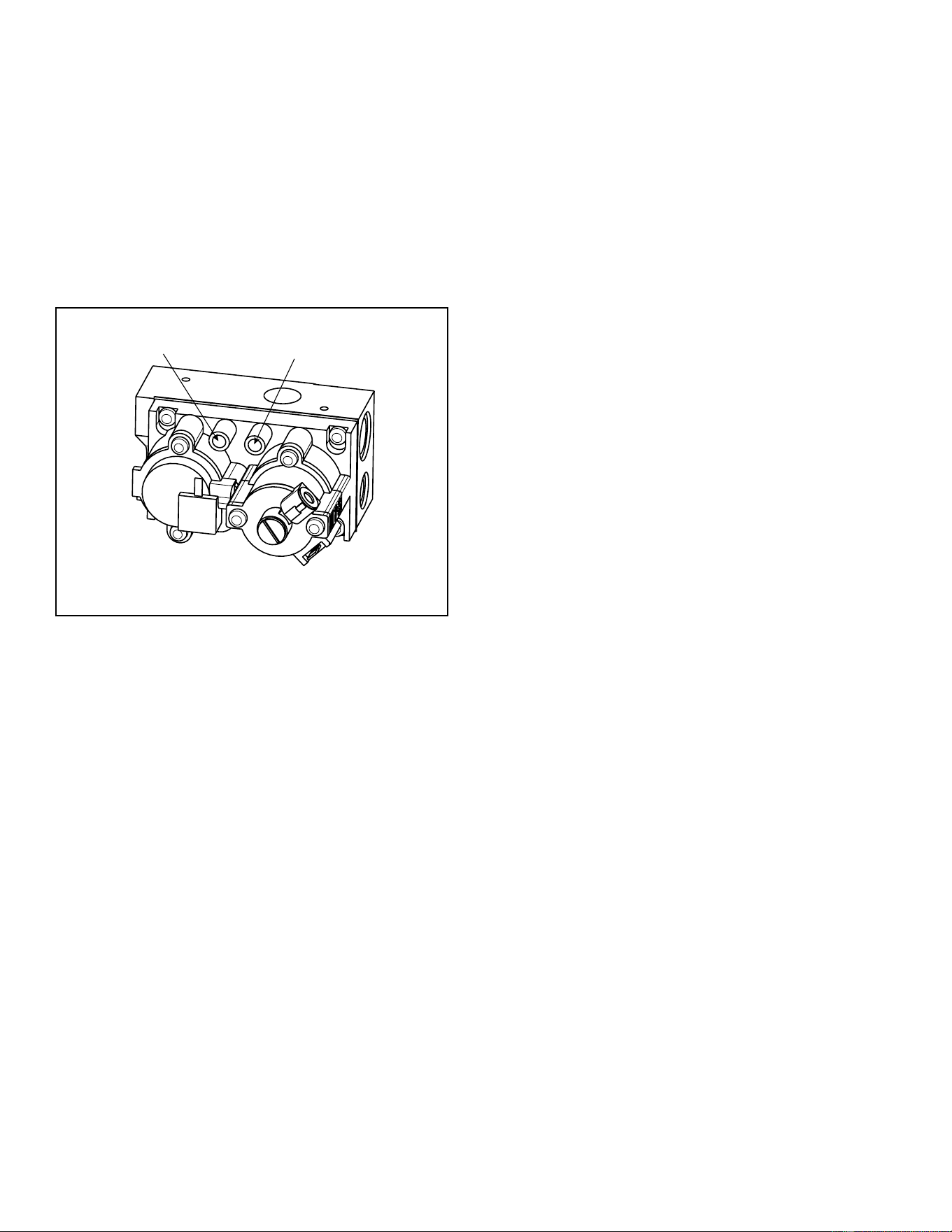
Outlet
Gas Valve
Inlet
The valve regulator controls the burner pressure. Gas
pressure must be verified at both the inlet and outlet
pressure test ports.
1. Turn captured screw counterclockwise two or three
turns. See Figure 5.2.
2. Place tubing from pressure gauge over test port.
3. After taking pressure readings, be sure and turn
captured screw clockwise firmly to re-seal. Do not
over torque.
4. Check for gas leaks.
D. Verify Gas Pressure
Figure 5.2 Pressure Test Ports
Hearth & Home Technologies • Stadium Installation Manual • 4004-900 Rev. B • 03/25
16
66
Electrical Information
WARNING! Risk of Shock or Explosion! DO NOT
wire 110-120 VAC to the valve. Incorrect wiring will dam-
age controls.
• The intermittent pilot ignition system (IPI) on the Sta-
dium series gas log set comes standard with an inte-
grated battery pack, that holds (2) D size batteries.
• The appliance does NOT require 110 VAC for opera-
tion. If the vented fireplace/firebox the appliance is
installed in is electrically wired, it must be wired and
grounded in accordance with local codes or, in the
absence of local codes, with National Electric Code
ANSI/NFPA 70-latest edition.
• An ON/OFF Switch and Remote Control are supplied
with the appliance. The Remote Control can be incor-
porated into this system by connecting to the remote
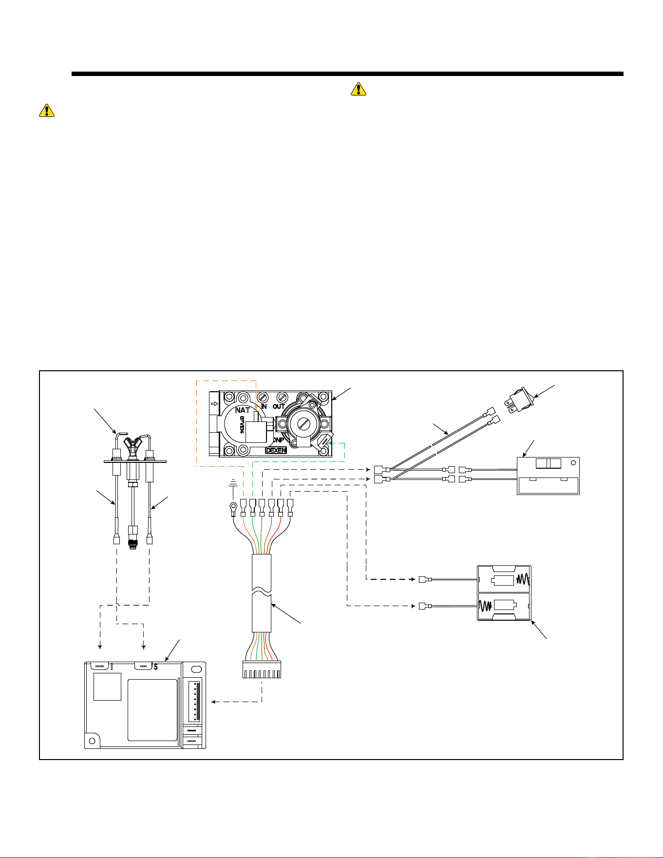
switch wires as shown. See Figure 6.1
NOTE: The use of a thermostat is prohibited in vented
log installations.
I S
PILOT
ON
RS
OFF
WHITE
ORANGE
CONTROL
MODULE
GAS VALVE
BATTERY
PACK
WIRE
HARNESS
REMOTE
CONTROL
ON/OFF
SWITCH
WIRE HARNESS:
BLACK = GROUND
ORANGE = VALVE
GREEN = VALVE
BROWN = SWITCH
BLACK = BATTERY (-)
RED = BATTERY (+)
WARNING! Risk of Shock! Label all wires prior to
disconnection when servicing controls. Wiring errors can
cause improper and dangerous operation. Verify proper
operation after servicing. Replace damaged wire with
type 105º C rated wire. Wire must have high temperature
insulation.
A. Wiring Requirements
Figure 6.1 IPI Wiring Diagram
Hearth & Home Technologies • Stadium Installation Manual • 4004-900 Rev. B • 03/25

17
77
Appliance Installation and Set-up
The appliance is assembled with the gas controls installed
at the factory, and is designed to connect the 3/8” supply
line before making final placement inside the fireplace.
1. Place the appliance towards the rear and center of
the fireplace and connect the gas line.
2. Tighten incoming gas connection. Follow instructions
in Section 5.C Gas Connection to check for gas leaks.
3. Center the gas log appliance in the fireplace. Make
certain the entire appliance and grate sit inside the
front edge of the fireplace. Ensure the appliance is
positioned correctly, side to side and front to back.
4. This appliance includes a battery box which holds 2
“D” size batteries. The battery box should be placed
in the right front corner of your fireplace and covered
with the log cover as shown in Figure 7.1.
Note: Proper installation of the appliance is essential to
prevent movement of the gas logs and controls during op-
eration.
You must secure the gas log appliance to the
fireplace floor. If not, the entire unit may move when
you adjust the controls. Movement of unit may cause
shifting of the gas logs which leads to sooting and
improper burning. Grate movement could cause a
gas leak.
WARNING
Figure 7.1 Batteries and Log Cover
This vented log set comes supplied with an On/Off Switch
and a battery powered remote control kit.
• The On/Off switch is located on the front right side of
the burner assembly as shown in Figure 7.2.
• The supplied remote control can be incorporated with
this system by connecting the remote wires to the
connection wires shown in Figure 7.2.
Note: Position the remote control receiver in a convenient
location, which allows for safe operation of the appliance
and replacement of batteries, as necessary.
A. Positioning the Appliance
B. On/Off Switch and Remote Control
Figure 7.2 On/Off Switch and Remote Connection
Hearth & Home Technologies • Stadium Installation Manual • 4004-900 Rev. B • 03/25
18
The positioning of the grate, logs and media is criti-
cal to the safe and clean operation of this appliance.
Sooting and other problems may result if the logs
are not properly positioned in the appliance. Never
add additional logs or embellishments such as pine
cones. Only use the logs and media supplied with
the unit.
Failure to position the parts in accordance with
installation instructions or failure to use only parts
specifically approved for this appliance may result
in property damage or personal injury.
Note: Be sure NOT to cover Pilot Assembly.
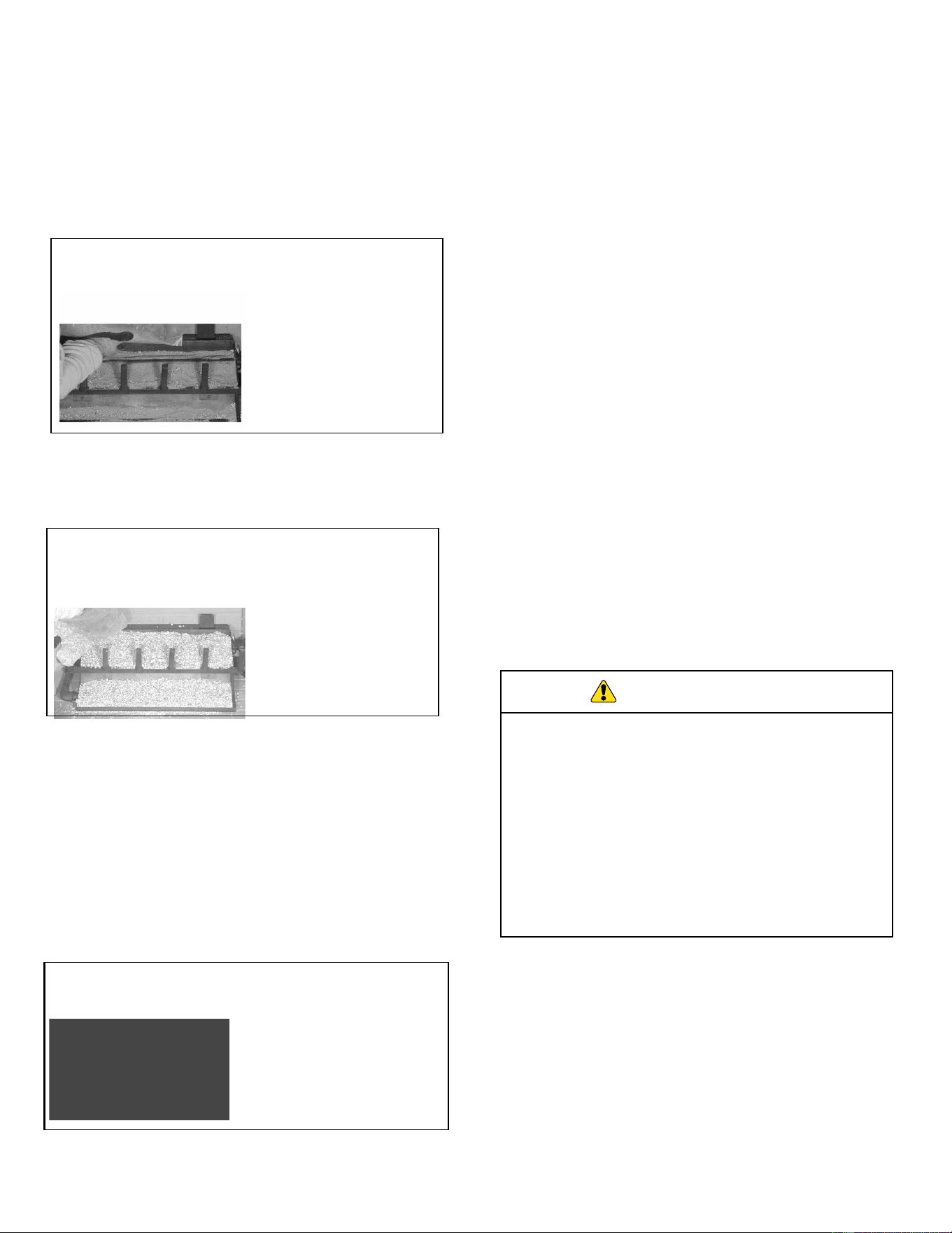
Figure 7.3 Sand Placement
3. Pour vermiculite over the sand in each pan until they
are full. See Figure 7.4.
Figure 7.4 Vermiculite Placement
4. Lightly place dime-size pieces of rock wool evenly all
over the vermiculite to achieve a glowing ember
effect. See Figure 7.5.
Note: For best results, do not pack down the rock wool.
The placement of rock wool can have an effect on flame
pattern and may need to be adjusted to achieve a desired
appearance.
5.
Inspect the Pilot Assembly to ensure it is clear of any
sand, vermiculite or rock wool.
6. Remove the Platinum Bright Embers™ from the
package. For optimum performance peel each piece
apart in layers and lightly place on top of the rock
wool where the flame is blue. This will achieve the
desired realism.
Note: Gas burns at the point of the least resistance. In
the case of an uneven flame pattern it may be necessary
to adjust the media material in the pans, using an object
such as a screwdriver, to achieve the desired effect.
DO NOT:
• Pile the glowing embers too heavily on the pan.
• Cover the pilot with glowing embers
Decorative Lava Rock Placement:
1. Place desired amount of decorative lava rock on the
floor of the fireplace.
2. Ensure all controls and switches are unobstructed
after decorative lava rock has been placed.
DO NOT:
• Place decorative lava rock on the burner, pilot or
logs.
• Allow decorative lava rock to come in contact
with the flames. Lava rocks may contain moisture
which, when heated, may cause it to popout during
operation.
WARNING
C. Natural Gas Set-up
Burner Media Placement:
1. Pour sand into each burner pan to the point where the
burner pipe is covered.
2. Level the sand from side to side to ensure an even
flame pattern. At this point the pans should be half
full. See Figure 7.3.
2TR
2TR
3TR
3TR
Figure 7.5 Rock Wool Placement
3TR
2TR
Hearth & Home Technologies • Stadium Installation Manual • 4004-900 Rev. B • 03/25

19
An explosion could occur if a connection is made
directly to an unregulated propane (LP) tank.
WARNING
Burner Media Placement:
1. Pour vermiculite into each burner pan to the point
where each pan is completely full.
2. Level the vermiculite from side to side to ensure
an!even flame pattern. See Figure 7.6.
Note: Be sure NOT to cover Pilot Assembly.
Figure 7.6 Vermiculite Placement
Pour vermiculite into each burner pan (LP) to the
point where each pan is completely full. Failure to
do so may cause the lighting to be delayed and this
can be dangerous.
WARNING
3. Lightly place dime-size pieces of rock wool evenly all
over the vermiculite to achieve a glowing ember
effect. See Figure 7.7.
Note: For best results, do not pack down the rock wool.
The placement of rock wool can have an effect on flame
pattern and may need to be adjusted to achieve a desired
appearance.
4. Inspect the Pilot Assembly to ensure it is clear of any
vermiculite or rock wool.
5. Remove the Platinum Bright Embers™ from the
package. For optimum performance peel each piece
apart in layers and lightly place on top of the rock
wool where the flame is blue. This will achieve the
desired realism.
Note: Gas burns at the point of the least resistance. In
the case of an uneven flame pattern it may be necessary
to adjust the media material in the pans, using an object
such as a screwdriver, to achieve the desired effect.
DO NOT:
•
Pile the glowing embers too heavily on the pan.
• Cover the pilot with glowing embers
Decorative Lava Rock Placement:
1. Place desired amount of decorative lava rock on the
floor of the fireplace.
2. Ensure all controls and switches are unobstructed
after decorative lava rock has been placed.
DO NOT:
• Place decorative lava rock on the burner, pilot or
logs.
• Allow decorative lava rock to come in contact
with the flames. Lava rocks may contain moisture
which, when heated, may cause it to popout during
operation.
• Cover the air mixer located on the lower left side of
the burner.
E. Log Placement
The Stadium series vented log set has multiple log op-
tions to choose from. These logs are sold seperately.
For log placement instructions refer to the installation in-
structions supplied with the log set.
NOTE: The appliance is designed to be operated with
one of the optional log sets installed. Do NOT operate this
appliance without a log set installed.
D. Propane (LP) Gas Set-up
3TR
2TR
Figure 7.7 Rock Wool Placement
2TR
2TR
Hearth & Home Technologies • Stadium Installation Manual • 4004-900 Rev. B • 03/25
20
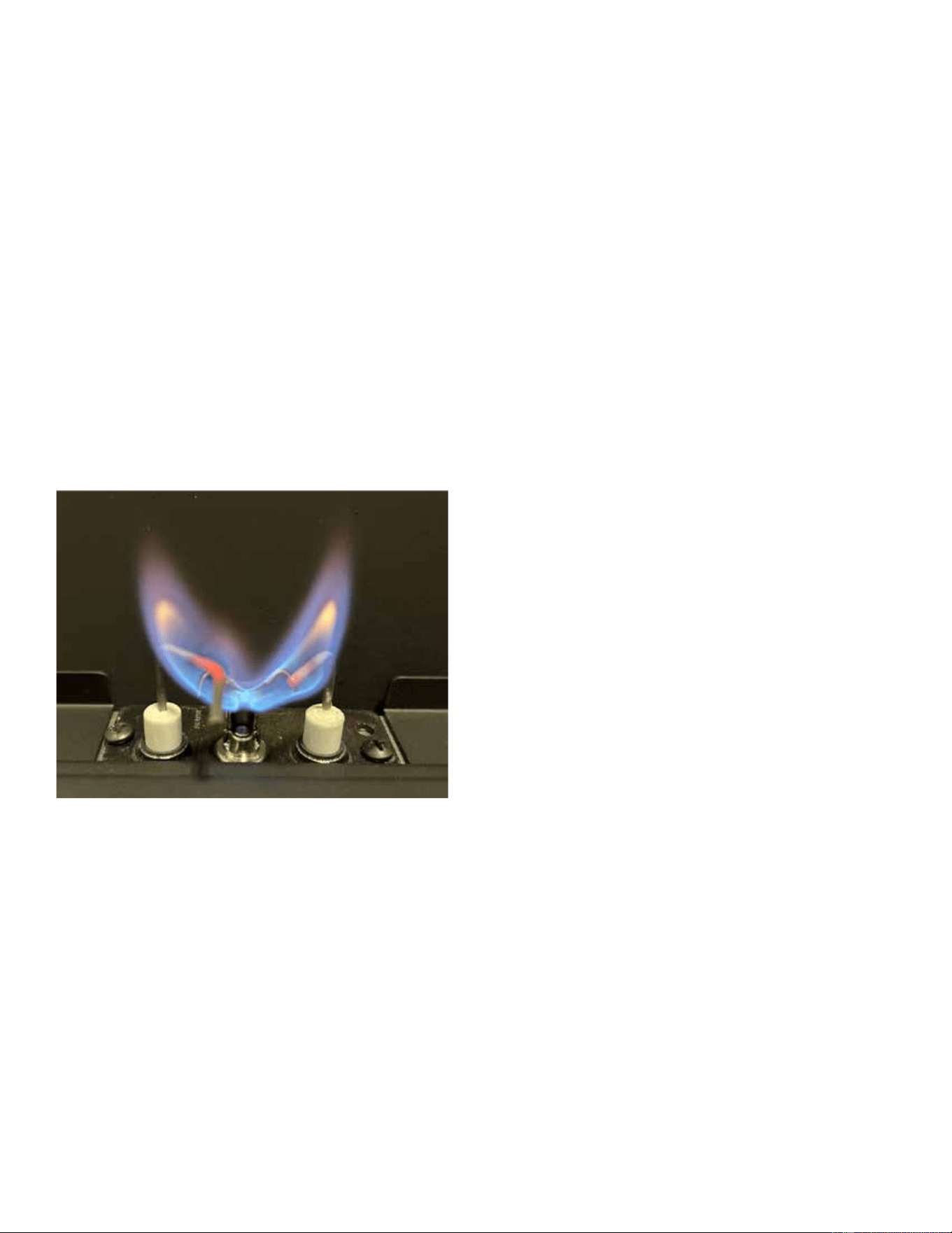
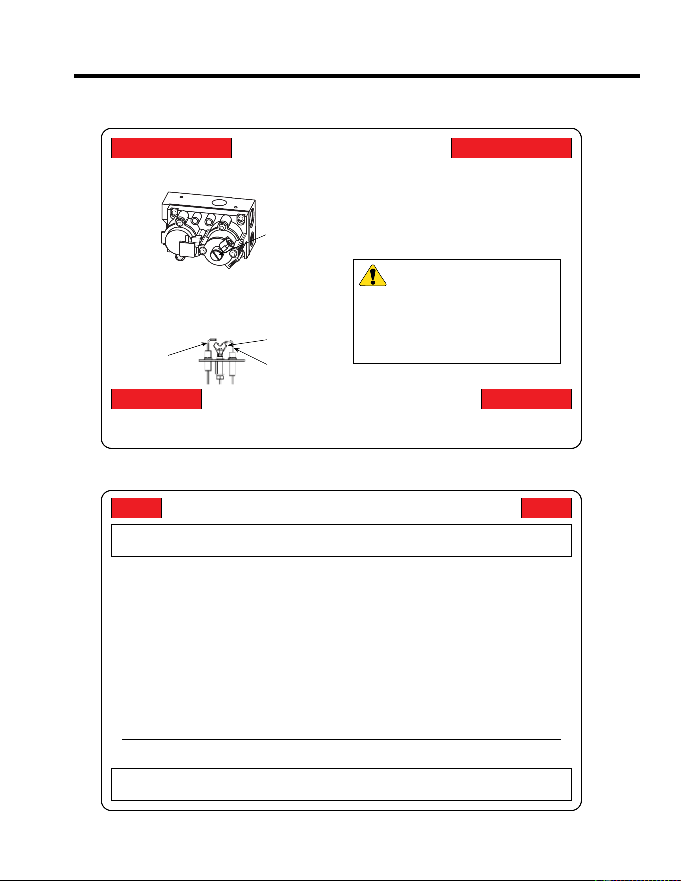
Figure 7.8 IPI Pilot Flame
Main Burner Flame:
Operate the appliance at full rate for 45 minutes, the fol-
lowing flame appearances should be observed.
Burner will have a random pattern of yellow flames, with
glowing embers covering the main burner.
Note: This appliance is a vented gas log set, therefore
some flame impingement and soot is normal.
Avoid any drafts that alter burner flame patterns. Do not
allow fans to blow directly on the appliance. Do not place
a blower inside the burn area of the fireplace. Ceiling fans
may create drafts that alter flame patterns. Sooting and
improper burning will result.
• Verify all shipping material have been removed from
inside and/or underneath the gas log set.
• Review proper placement of logs.
• Ensure there are no gas leaks.
• The burner should run three to four hours continu-
ously on high.
• Turn the burner off and allow it to completely cool.
This cures the materials used to manufacture the burner.
NOTICE! Open windows for air circulation during appli-
ance break-in.
• Some people may be sensitive to smoke and odors.
• Smoke detectors may activate.
F. Before Lighting Appliance
Before operating this appliance for the first time, have a
qualified service technician:
Caution: This appliance must NOT be operated with glass
doors in the closed position.
G. Flame Appearance
Flames from the pilot and burner should be visually
checked as soon as the appliance is installed. In addition,
periodically check the fl
ames visually during operation.
Pilot Flame:
The IPI pilot flame must always be present when the appli-
ance is in operation. Pilot flame should engulf the flame
sensor rod. See Figure 7.8.
If the pilot flame does not touch the flame sensor, then the
main burner cannot function reliably.
H. Initial Use
Initial Break-in Procedure:
Hearth & Home Technologies • Stadium Installation Manual • 4004-900 Rev. B • 03/25
21
88
Lighting Instructions
A. Intermittent Pilot (IPI)
LIGHTING INSTRUCTIONS
1. STOP! Read the safety instruction label.
2. Turn wall switch to the “OFF” position.
3. Wait five minutes to clear out any gas. If you
smell gas, STOP! Follow “B” on the safety
information label. If you don’t smell gas, go to
next step.
4. Locate pilot assembly inside unit.
GAS
CONTROL
KNOB
FLAME
SENSOR
PILOT
BURNER
IGNITOR
TO TURN OFF GAS TO APPLIANCE
5. To light pilot and main burner, turn wall switch to
“ON”. Don not light by hand.
6. If appliance will not operate, follow the
instructions “TO TURN OFF GAS TO APPLI-
ANCE” and call your service technician or gas
supplier.
1. Turn on/off switch to “OFF”
WARNING:
This product and the fuels
used to operate this product (liquid
propane or natural gas), and the products of
combustion of such fuels, can expose you to
chemicals including benzene, which is
known to the State of California to cause
cancer and reproductive harm. For more
information go to: www.P65Warnings.ca.gov.
FOR YOUR SAFETY READ BEFORE LIGHTING
WARNING: If you do not follow these instructions exactly, a fire or explosion may
result causing property damage, personal injury or loss of life.
A. This appliance has an intermittent pilot. When
lighting the pilot, follow these instructions
exactly.
B. BEFORE LIGHTING smell all around the
appliance area for gas. Be sure to smell next to
the floor bacause some gas is heavier than air
and will settle to the floor.
WHAT TO DO IF YOU SMELL GAS
• Do not try to light any appliance.
• Do not touch any electric switch; do not
use any phone in your building.
• Immediately call your gas supplier from a
neighbor’s phone. Follow the gas
supplier’s instructions.
• If you cannot reach your gas supplier, call
the fire department.
C. Do not use this appliance if any part has been
under water. Immediately call a qualified service
technician to inspect the appliance and to
replace any part of the control system and any
gas control whcih has been under water.
FOR YOUR SAFETY: Do not store or use gasoline or other flammable vapors and
liquids in the vicinity of this or any other appliance.
Due to high surface temperatures, keep children, clothing and furniture away.
Keep burner and control compartment clean. See installation instructions accompanying the appliance.
Hearth & Home Technologies • Stadium Installation Manual • 4004-900 Rev. B • 03/25

22
Any safety screen removed for servicing must be replaced
prior to operating the appliance.
Task
Frequency To be completed by
Pilot Inspection &
Cleaning
Annually
Qualified Service
Technician
Log Inspection
Annually
Firebox Inspection
Annually
Burner Ignition &
Operation
Annually
The matrix below is an overview of maintenance tasks to
be performed on the appliance. Section B gives details
and instructions needed to assist the appropriate person
in performing the tasks.
When properly maintained, your appliance will give you
many years of trouble-free service. Contact your dealer
to answer questions regarding proper operation, trouble-
shooting and service for your appliance.
Visit www.hearthnhome.com to locate a dealer. We rec-
ommend annual service by a qualified service technician.
The following tasks must be performed by a qualified ser-
vice technician.
Pilot Inspection & Cleaning
Frequency: Annually
By: Qualified Service Technician
Tools needed: Small soft brush, pipe cleaner
• Inspect and remove dust, spider webs and lint
• Gently run pipe cleaner through air intake port
• Inspect IPI flame sensing rod for soot, corrosion an
deterioration. Polish with 320 grit Emery cloth and/or
3M™ Scotch-Brite Abrasive Hand Pad.
Log Inspection
Frequency: Annually
By: Qualified Service Technician
Tools needed: Small soft brush
• Inspect for broken, cracked or misplaced logs
• Gently remove any dust and/or soot buildup
Firebox Inspection
Frequency: Annually
By: Qualified Service Technician
Tools needed: Protective gloves, sandpaper, steel wool,
cloths, mineral spirits, primer and touch-up paint.
• Inspect for paint condition, warped surfaces, corrosion
or perforation. Sand and repaint as necessary.
• Replace fireplace if firebox has been perforated.
Burner Ignition and Operation
Frequency: Annually
By: Qualified Service Technician
Tools needed: Protective gloves, vacuum cleaner, whisk
broom, flashlight, voltmeter, indexed drill bit set, and a
manometer.
• Verify burner is properly secured and aligned with pilot
or igniter.
• Clean off burner top, inspect for plugged ports,
corrosion or deterioration. Replace burner if necessary
• Inspect for lifting or other flame problems.
• Inspect orifice for soot, dirt and corrosion. Verify orifice
size is correct. See Service Parts List for proper orifice
sizing.
• Verify manifold and inlet pressures. Adjust regulator
as required.
• Inspect pilot flame pattern and strength. Clean or
replace orifice spud as necessary.
99
Maintenance and Service
A. Maintenance: Frequency and Tasks
B.
Maintenance Tasks: Qualified Service
Technician
Remote and Battery
Pack inspection
Annually
Hearth & Home Technologies • Stadium Installation Manual • 4004-900 Rev. B • 03/25

23
C. Cleaning and Servicing
Annual inspection and cleaning by your dealer or quali-
fied service technician is recommended to prevent mal-
function and/or sooting.
Caution! Before cleaning make sure the appliance
is cool and the power to the unit is turned off.
Note: During normal operation it is common that some
sooting may occur on the logs as well as internal panels.
This can be more prevalent with propane (LP). Clean soot
from the appliance as frequently as necessary to eliminate
a buildup of soot or permanent discoloration.
Periodic Cleaning:
• Remove logs carefully, by holding gently at each end.
Gloves are recommended to prevent skin irritation. If
skin irritation occurs, wash gently with soap and water.
Refer to installation manual for correct log placement.
• Do NOT use cleaning fluid to clean logs or any part of
the appliance.
• Brush logs with soft bristle brush or vacuum with brush
attachment.
• Vacuum loose particles and dust from the burner,
controls and grate weldment.
• Replace battery in remote control device.
Annual Cleaning/Inspection:
• Inspect and clean burner air intake shutter. Remove
lint or particles with vacuum, brush, or pipe cleaners.
Failure to keep air intake shutter clean may result
in sooting and/or poor combustion.
• Inspect and clean all burner ports.
• Inspect pilot for proper operation.
• Verify flame pattern and log placement for proper
operation.
• Verify smooth and responsive ignition of main burner
If not using the appliance for an extended period (e.g.: summer months, vacation/trips, etc.):
• Remove batteries from remote and battery pack
to avoid corrosion.
Hearth & Home Technologies • Stadium Installation Manual • 4004-900 Rev. B • 03/25

24
With proper installation, operation and maintenance your gas appliance will provide years of trouble-free service. If you
do experience a problem, this troubleshooting guide will assist a qualified service technician in the diagnosis of a problem
and the corrective action to be taken. This troubleshooting guide should only be used by a qualified service technician.
Contact a dealer to arrange a service call by a qualified service technician.
IntelliFire™ Ignition System
ISSUE SOLUTION
Odor from appliance
When first operated, this appliance may release an odor for the first several hours. This
is caused by the burning off of any oils remaining from manufacturing. Odor may also be
released from finishing materials and adhesives used around the appliance.
Metallic noise
Noise is cause by metal expanding and contracting as it heats up and cools down, similar
to the sound produced by a furnace or heating duct. This noise does not affect the opera-
tion or longevity of the appliance.
Wall above appliance feels
hot to the touch
The area around, specifically above the firebox opening will become hot to the touch dur-
ing operation. This is normal, no action is necessary.
SYMPTOM POSSIBLE CAUSE CORRECTIVE ACTION
Pilot won’t light. The igni-
tion/module makes noise,
but no spark.
Incorrect Wiring
Verify sensor wire (white) and igniter wire (orange) are con-
nected to correct terminals on module and pilot assembly.
Loose connections or elec-
trical shorts in the wiring
Verify no loose connections or electrical shorts in wiring from
module to pilot assembly. Verify connections underneath
pilot assembly are tight; also verify igniter and flame sense
wires are not grounding out to metal chassis, pilot burner,
pilot enclosure, mesh screen if present, or any other metal
object.
Ignitor gap is too large
Verify gap of igniter to right side of pilot hood. The gap
should be approximately .125 in. or 1/8 in. (3 mm).
Pilot won’t light. There is
no noise or spark.
Bad/Dead Batteries
Replace (2) D size batteries, located on the right side of ap-
pliance.
A shorted or loose connec-
tion in wiring configuration
or wire harness.
Remove and reinstall the wiring harness that plugs into mod-
ule. Verify there is a tight fit. Verify pilot assembly wiring to
module. Remove and verify continuity of each wire in wiring
harness. Replace any damaged components.
Module not grounded
Verify black ground wire from module wire harness is
grounded to metal chassis of appliance.
10 10
Troubleshooting
A. Frequently Asked Questions
B. Troubleshooting
Hearth & Home Technologies • Stadium Installation Manual • 4004-900 Rev. B • 03/25

25
IntelliFire™ Ignition System (Continued)
SYMPTOM POSSIBLE CAUSE CORRECTIVE ACTION
Pilot sparks, but will not
light.
Pilot covered with
media.
Verify that the pilot is clear of all media. If covered, remove
media and restart.
No gas supply.
Verify that incoming gas line ball valve is “open”. Verify that
inlet pressure reading is within acceptable limits.
Ignitor gap is too large.
Verify gap of igniter to right side of pilot hood. The gap
should be approximately .125 in. or 1/8 in. (3 mm).
Module is not grounded.
Verify module is securely grounded to metal chassis of appli-
ance.
Pilot valve solenoid
Verify that 1.5 to 1.8 VDC is supplied to pilot solenoid from
module. If below 1.5 volts, replace module. If 1.5 volts or
greater, replace valve.
Pilot lights but continues
to spark, and burner will
not ignite. (If the pilot
continues to spark after
the pilot flame has been
lit, flame rectification
has not occurred).
A short or loose con-
nection in flame sensing
rod.
Verify all connections to wiring diagram in manual. Verify
connections underneath pilot assembly are tight. Verify con-
nections are not grounding out to metal chassis, pilot burner,
pilot enclosure or screen if present, or any other metal
object.
Poor flame rectification
or contaminated flame
sensing rod.
Verify correct pilot orifice is installed and gas inlet is set to
pressure specifications. Check pilot for soot. Clean if neces-
sary.
Module is not grounded.
Verify module is securely grounded to metal chassis of ap-
pliance. Verify that wire harness is firmly connected to the
module.
Damaged pilot assem-
bly or contaminated
flame sensing rod.
Verify that ceramic insulator around the flame sensing rod
is not cracked, damaged, or loose. Verify connection from
flame sensing rod to white sensor wire. Polish flame sens-
ing rod with fine steel wool to remove any contaminants that
may have accumulated on flame sensing rod. Verify continu-
ity with a multimeter with ohms set at lowest range. Replace
pilot if any damage is detected.
Module
Turn wall control to OFF position. Remove ignitor wire “I”
from module. Turn wall control to "ON" position. If there is no
spark at “I” terminal module must be replaced. If there is a
spark at “I” terminal, module is fine.
Contact your dealer for additional information regarding operating and troubleshooting.
Visit www.hearthnhome.com to locate a dealer
Hearth & Home Technologies • Stadium Installation Manual • 4004-900 Rev. B • 03/25
26
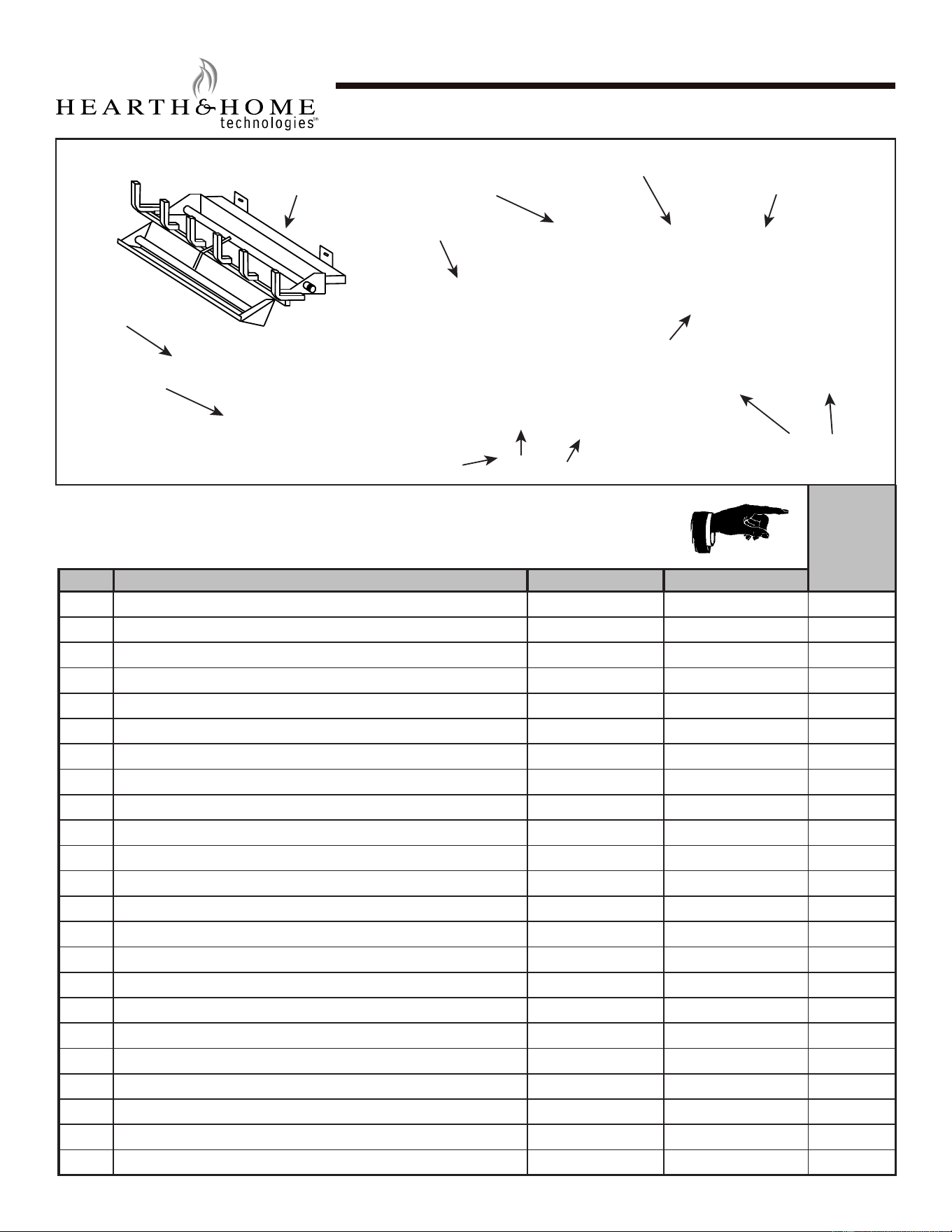
Service Parts
Beginning Manufacturing Date:
Ending Manufacturing Date: Active
2TR-IPI-R18-N / 2TR-IPI-R18-P
2-Tier Stadium 18” Hearth Kit
IMPORTANT: THIS IS DATED INFORMATION. Parts must be ordered from a dealer or distributor. Hearth
and Home Technologies does not sell directly to consumers. Provide model number and serial number
when requesting service parts from your dealer or distributor.
Stocked
at Depot
ITEM DESCRIPTION COMMENTS PART NUMBER
1 Burner Pan & Grate Assembly BPA-300-18
2 Flexible Connector FT-1-18
3 Damper Clamp SRV500-SC
4 On/Off Switch 01-1070
5 On/Off Switch Wiring Harness 16-1615
6 NG Pilot Assembly 07-1024
6 LP Pilot Assembly 07-1023 Y
7 Control Module
SRV593-592
Y
8 Battery Pack SRV593-594 Y
9 NG Valve SRV593-500 Y
9 LP Valve SRV593-501
10 Valve Bracket MT-350-VC
11 Control Box MT-350-BBA18
12 Control Box Mount MT-350-CBMS18
13 Wire Harness SRV593-590 Y
Battery Cover Log H-0586A
Remote Control RCB
Lava Rock
Qty 2 SRVACC10
Vermiculite (Large) SRVACC11
Embers SRVACC12
Platinum Embers PBE-5
Sand (Natural Gas Only) SRVACC15
Installation Manual 4004-900
2
1
4
5
6
9
7
8
11
10
3
12
13
Hearth & Home Technologies • Stadium Installation Manual • 4004-900 Rev. B • 03/25
Service Parts
Beginning Manufacturing Date:
Ending Manufacturing Date: Active
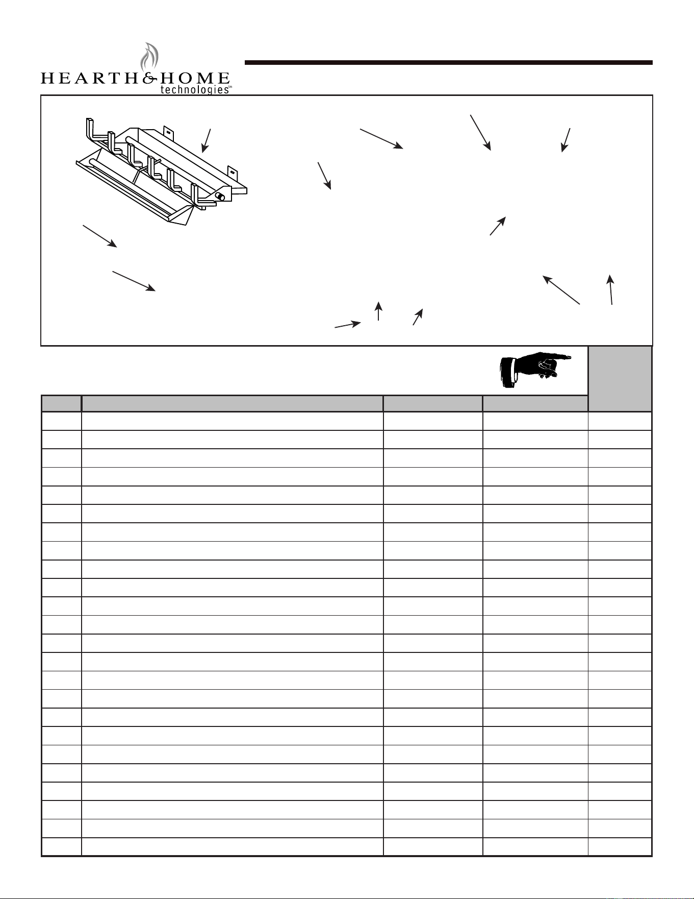
2TR-IPI-R24-N / 2TR-IPI-R24-P
2-Tier Stadium 24” Hearth Kit
IMPORTANT: THIS IS DATED INFORMATION. Parts must be ordered from a dealer or distributor. Hearth
and Home Technologies does not sell directly to consumers. Provide model number and serial number
when requesting service parts from your dealer or distributor.
Stocked
at Depot
ITEM DESCRIPTION COMMENTS PART NUMBER
1 Burner Pan & Grate Assembly BPA-300-24
2 Flexible Connector FT-1-24
3 Damper Clamp SRV500-SC
4 On/Off Switch 01-1070
5 On/Off Switch Wiring Harness 16-1615
6 NG Pilot Assembly 07-1024
6 LP Pilot Assembly 07-1023 Y
7 Control Module
SRV593-592
Y
8 Battery Pack SRV593-594 Y
9 NG Valve SRV593-500 Y
9 LP Valve SRV593-501
10 Valve Bracket MT-350-VC
11 Control Box MT-350-BBA18
12 Control Box Mount MT-350-CBMS18
13 Wire Harness SRV593-590 Y
Battery Cover Log H-0586A
Remote Control RCB
Lava Rock
Qty 2 SRVACC10
Vermiculite (Large) SRVACC11
Vermiculite (Small) SRVACC11
Embers SRVACC12
Platinum Embers PBE-5
Sand (Natural Gas Only) SRVACC15
Installation Manual 4004-900
2
1
4
5
6
9
7
8
11
10
3
12
13
27
Hearth & Home Technologies • Stadium Installation Manual • 4004-900 Rev. B • 03/25
Service Parts
Beginning Manufacturing Date:
Ending Manufacturing Date: Active
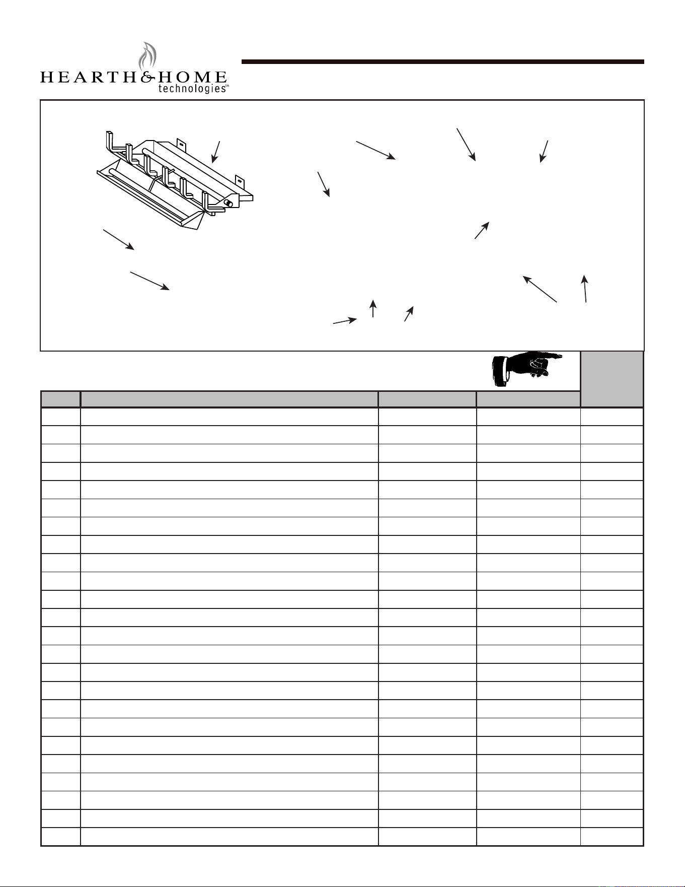
2TR-IPI-R30-N / 2TR-IPI-R30-P
2-Tier Stadium 30” Hearth Kit
IMPORTANT: THIS IS DATED INFORMATION. Parts must be ordered from a dealer or distributor. Hearth
and Home Technologies does not sell directly to consumers. Provide model number and serial number
when requesting service parts from your dealer or distributor.
Stocked
at Depot
ITEM DESCRIPTION COMMENTS PART NUMBER
1 Burner Pan & Grate Assembly BPA-300-30
2 Flexible Connector FT-1-30
3 Damper Clamp SRV500-SC
4 On/Off Switch 01-1070
5 On/Off Switch Wiring Harness 16-1615
6 NG Pilot Assembly 07-1024
6 LP Pilot Assembly 07-1023 Y
7 Control Module
SRV593-592
Y
8 Battery Pack SRV593-594 Y
9 NG Valve SRV593-500 Y
9 LP Valve SRV593-501
10 Valve Bracket MT-350-VC
11 Control Box MT-350-BBA18
12 Control Box Mount MT-350-CBMS18
13 Wire Harness SRV593-590 Y
Battery Cover Log H-0586A
Remote Control RCB
Lava Rock
Qty 2 SRVACC10
Vermiculite (Large) SRVACC11
Vermiculite (Small) SRVACC11
Embers SRVACC12
Platinum Embers PBE-5
Sand (Natural Gas Only)
Qty 2 SRVACC15
Installation Manual 4004-900
2
1
4
5
6
9
7
8
11
10
3
12
13
28
Hearth & Home Technologies • Stadium Installation Manual • 4004-900 Rev. B • 03/25
Service Parts
3TR-IPI-R18-N / 3TR-IPI-R18-P
Beginning Manufacturing Date:Feb 2025
Ending Manufacturing Date: Active
3-Tier Stadium 18” Hearth Kit
IMPORTANT: THIS IS DATED INFORMATION. Parts must be ordered from a dealer or distributor. Hearth
and Home Technologies does not sell directly to consumers. Provide model number and serial number
when requesting service parts from your dealer or distributor.
Stocked
at Depot
ITEM DESCRIPTION COMMENTS PART NUMBER
1 Burner Pan & Grate Assembly BPA-300-33
2 Flexible Connector FT-1-18
3 Damper Clamp SRV500-SC
4 On/O Switch 01-1070
5 On/O Switch Wiring Harness 16-1615
6 NG Pilot Assembly 07-1024
6 LP Pilot Assembly 07-1023 Y
7 Control Module
SRV593-592
Y
8 Battery Pack SRV593-594 Y
9 NG Valve SRV593-500 Y
9 LP Valve SRV593-501
10 Valve Bracket MT-350-VC
11 Control Box MT-350-BBA18
12 Control Box Mount MT-350-CBMS18
13 Wire Harness SRV593-590 Y
Battery Cover Log H-0586A
Remote Control RCB
Lava Rock
Qty 2 SRVACC10
Vermiculite (Small)
Qty 2 SRVACC11
Embers SRVACC12
Platinum Embers PBE-5
Sand (Natural Gas Only)
Qty 2 SRVACC15
Installation Manual 4004-900
2
1
4
5
6
9
7
8
11
10
3
12
13
29
Hearth & Home Technologies • Stadium Installation Manual • 4004-900 Rev. B • 03/25
30
Service Parts
3TR-IPI-R24-N / 3TR-IPI-R24-P
Beginning Manufacturing Date:Feb 2025
Ending Manufacturing Date: Active
3-Tier Stadium 24” Hearth Kit
IMPORTANT: THIS IS DATED INFORMATION. Parts must be ordered from a dealer or distributor. Hearth
and Home Technologies does not sell directly to consumers. Provide model number and serial number
when requesting service parts from your dealer or distributor.
Stocked
at Depot
ITEM DESCRIPTION COMMENTS PART NUMBER
1 Burner Pan & Grate Assembly BPA-300-35
2 Flexible Connector FT-1-24
3 Damper Clamp SRV500-SC
4 On/O Switch 01-1070
5 On/O Switch Wiring Harness 16-1615
6 NG Pilot Assembly 07-1024
6 LP Pilot Assembly 07-1023 Y
7 Control Module
SRV593-592
Y
8 Battery Pack SRV593-594 Y
9 NG Valve SRV593-500 Y
9 LP Valve SRV593-501
10 Valve Bracket MT-350-VC
11 Control Box MT-350-BBA18
12 Control Box Mount MT-350-CBMS18
13 Wire Harness SRV593-590 Y
Battery Cover Log H-0586A
Remote Control RCB
Lava Rock
Qty 2 SRVACC10
Vermiculite (Large) SRVACC11
Embers
Qty 2 SRVACC12
Platinum Embers
qty 2 PBE-5
Sand (Natural Gas Only) SRVACC15
Installation Manual 4004-900
2
1
4
5
6
9
7
8
11
10
3
12
13
Hearth & Home Technologies • Stadium Installation Manual • 4004-900 Rev. B • 03/25
Service Parts
3TR-IPI-R30-N / 3TR-IPI-R30-P
Beginning Manufacturing Date:Feb 2025
Ending Manufacturing Date: Active
3-Tier Stadium 30” Hearth Kit
IMPORTANT: THIS IS DATED INFORMATION. Parts must be ordered from a dealer or distributor. Hearth
and Home Technologies does not sell directly to consumers. Provide model number and serial number
when requesting service parts from your dealer or distributor.
Stocked
at Depot
ITEM DESCRIPTION COMMENTS PART NUMBER
1 Burner Pan & Grate Assembly BPA-300-40
2 Flexible Connector FT-1-30
3 Damper Clamp SRV500-SC
4 On/O Switch 01-1070
5 On/O Switch Wiring Harness 16-1615
6 NG Pilot Assembly 07-1024
6 LP Pilot Assembly 07-1023 Y
7 Control Module
SRV593-592
Y
8 Battery Pack SRV593-594 Y
9 NG Valve SRV593-500 Y
9 LP Valve SRV593-501
10 Valve Bracket MT-350-VC
11 Control Box MT-350-BBA18
12 Control Box Mount MT-350-CBMS18
13 Wire Harness SRV593-590 Y
Battery Cover Log H-0586A
Remote Control RCB
Lava Rock
Qty 3 SRVACC10
Vermiculite (Large) SRVACC11
Vermiculite (Small) SRVACC11
Embers SRVACC12
Platinum Embers
Qty 3 PBE-5
Sand (Natural Gas Only)
Qty 2 SRVACC15
Installation Manual 4004-900
2
1
4
5
6
9
7
8
11
10
3
12
13
31
Hearth & Home Technologies • Stadium Installation Manual • 4004-900 Rev. B • 03/25

32
- NOTES -
DO NOT DISCARD THIS MANUAL
NOTICE
• Leave this manual with
party responsible for use
and operation.
• Important operating
and maintenance
instructions included.
• Read, understand and follow
these instructions for safe
installation and operation.
Hearth & Home Technologies
7571 215
th
Street West, Lakeville, MN 55044
www.hearthnhome.com
Please contact your dealer with any questions or concerns.
For the location of your nearest dealer,
please visit www.hearthnhome.com
B. Contact Information
Hearth & Home Technologies • Stadium Installation Manual • 4004-900 Rev. B • 03/25