www.klarstein.com
BARELLA
Dunstabzugshaube
Range Hood
Campana extractora
Hotte aspirante
Cappa aspirante
10037863 10037864 10037865

3
DE
Sehr geehrter Kunde,
wir gratulieren Ihnen zum Erwerb Ihres Gerätes. Lesen Sie
die folgenden Hinweise sorgfältig durch und befolgen Sie
diese, um möglichen Schäden vorzubeugen. Für Schäden,
die durch Missachtung der Hinweise und unsachgemäßen
Gebrauch entstehen, übernehmen wir keine Haftung.
Scannen Sie den folgenden QR-Code, um Zugriff auf die
aktuellste Bedienungsanleitung und weitere Informationen
rund um das Produkt zu erhalten.
INHALTSVERZEICHNIS
Sicherheitshinweise 4
Installation (Außenentlüftung) 6
Hinweise für den Einbau des Abluftrohrs 8
Bedienfeld 9
Bedienung 9
Fehlersuche und Fehlerbehebung 11
Reinigung und Pege 11
Hinweise zum Umweltschutz 15
Produktdatenblatt 16
Spezielle Entsorgungshinweise für Verbraucher in Deutschland 18
Hinweise zur Entsorgung 20
Hersteller & Importeur (UK) 20
TECHNISCHE DATEN
Artikelnummer 10037863, 10037864, 10037865
Stromversorgung 220-240 V ~ 50 Hz
English 21
Español 37
Français 53
Italiano 69

4
DE
SICHERHEITSHINWEISE
• Lesen Sie sich alle Hinweise vor der Benutzung sorgfältig durch und bewahren
Sie die Bedienungsanleitung zum späteren Nachschlagen gut auf.
• Die Montagearbeiten dürfen nur von einer Elektrofachkraft oder einer
qualizierten Person durchgeführt werden. Bevor Sie die Dunstabzugshaube
verwenden, stellen Sie sicher, dass die Spannung (V) und die auf der
Dunstabzugshaube angegebene Frequenz (Hz) der Spannung und Frequenz
der Stromversorgung in Ihrem Haushalt entsprechen.
• Für Schäden, die durch unsachgemäßen Gebrauch und
unsachgemäße Installation entstehen, übernehmen wir keine
Haftung.
• Kinder unter 8 Jahren dürfen die Dunstabzugshaube nicht benutzen.
• Das Gerät ist nicht für den kommerziellen Gebrauch, sondern nur für
Gebrauch im Haushalt und in ähnlichen Umgebungen vorgesehen.
• Reinigen Sie das Gerät und den Filter regelmäßig, damit das Gerät immer
ezient arbeitet.
• Ziehen Sie vor der Reinigung immer den Stecker aus der Steckdose.
• Reinigen Sie das Gerät genau wie in der Bedienungsanleitung angegeben.
• Verwenden Sie unter der Abzugshaube kein offenes Feuer.
• Falls das Gerät nicht normal funktioniert, wenden Sie sich an den Hersteller
oder einen Fachbetrieb.
• Kinder ab 8 Jahren, psychisch, sensorisch und körperlich eingeschränkte
Menschen dürfen das Gerät nur benutzen, wenn sie vorher von einer für
sie verantwortlichen Aufsichtsperson ausführlich mit den Funktionen und
den Sicherheitsvorkehrungen vertraut gemacht wurden und die damit
verbundenen Risiken verstehen.
• Falls das Netzkabel oder der Stecker beschädigt sind, müssen sie vom
Hersteller, einem autorisierten Fachbetrieb oder einer ähnlich qualizierten
Person ersetzt werden.
• Wenn die Dunstabzugshaube mit Herden verwendet wird, die Gas oder
andere Brennstoffe verbrennen, muss eine ausreichende Belüftung des
Raumes vorhanden sein.
• Flambieren Sie nicht unter der Abzugshaube.
• Achtung: Die Geräteoberäche kann während des Betriebs heiß werden.
Wichtige Hinweise zur Installation
• Die Luft darf nicht in einen Abzug abgeleitet werden, der zum Absaugen von
Rauchgasen von Gas- oder anderen Brennstoffen verwendet wird (gilt nicht
für Geräte, die nur die Luft in den Raum zurückführen).
• Beachten Sie alle regionalen Vorschriften zum Einbau von Entlüftungsanlagen.

5
DE
Wichtige Hinweise zum Abluftbetrieb
WARNUNG
Vergiftungsgefahr durch zurückgesaugte Abgase! Betreiben Sie
das Gerät nicht im Abluftbetrieb, wenn es zusammen mit einer
raumluftabhängigen Feuerstätte betrieben wird und keine
ausreichende Luftzirkulation garantiert wird.
Raumluftabhängige Feuerstätten wie Gas-, Öl-, Holz- oder Kohleheizungen, Boiler
oder Durchlauferhitzer beziehen die Luft aus dem Raum und führen sie durch
ein Abluftrohr oder einen Kamin ins Freie. Im Abluftbetrieb wird der Küche und
den benachbarten Räumen Luft entzogen. Ohne ausreichende Zuluft entsteht
ein Unterdruck. Giftige Gase aus dem Kamin oder Abluftrohr können dabei in die
Wohnräume zurückgesaugt werden.
• Achten Sie darauf, dass ausreichend Frischluftzufuhr garantiert ist und die
Luft zirkulieren kann.
• Ein Zuluft-/Abluftmauerkasten reicht nicht aus, um die Einhaltung des
Grenzwertes sicherzustellen.
Ein gefahrloser Betrieb ist nur dann möglich, wenn der Unterdruck am
Standort der Feuerstätte 4 Pa (0,04 mbar) nicht überschreitet. Das erreichen
Sie, wenn durch nicht-verschließbare Öffnungen in Türen und Fenstern in
Verbindung mit einem Zuluft- / Abluftmauerkasten die zur Verbrennung
benötigte Luft nachströmen kann. Lassen Sie sich in jedem Fall von einem
Schornsteinfegermeister beraten und den gesamten Lüftungsverbund des Hauses
beurteilen. Er kann ihnen gegebenenfalls die nötigen Maßnahme zur Belüftung
nennen.
Wird die Dunstabzugshaube ausschließlich im Umluftbetrieb eingesetzt, ist der
Betrieb ohne Einschränkung möglich.
Wichtige Hinweis zur Demontage des Geräts
• Die Demontage gleicht der Installation/Montage in umgekehrter Reihenfolge.
• Nehmen Sie sich bei der Demontage eine zweite Person zu Hilfe, um
Verletzungen zu vermeiden.

6
DE
INSTALLATION (AUSSENENTLÜFTUNG)
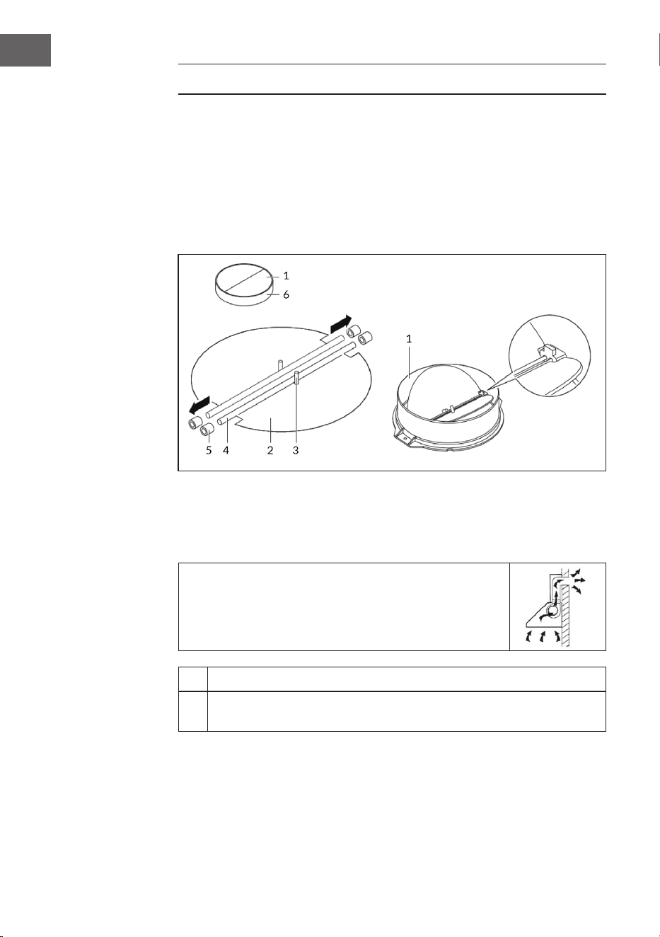
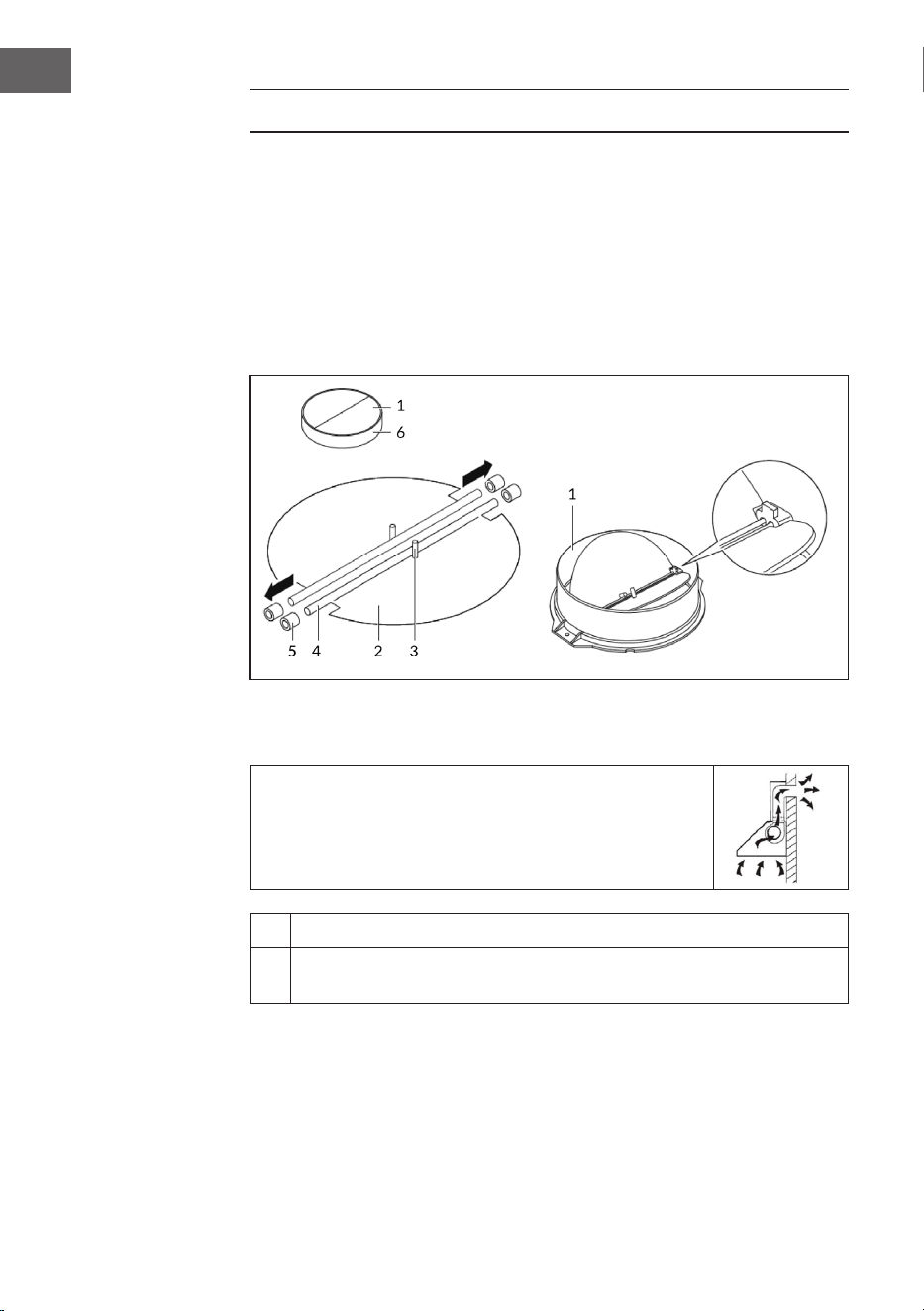
Montage der V-Klappe
Wenn die Dunstabzugshaube keine vormontierte V-Klappe hat, installieren Sie die
Teile folgendermaßen:
1. Bauen Sie die Erste Hälfte (2) in das Gehäuse (6) ein.
2. Der Pin (3) sollte nach oben gerichtet sein.
3. Die Achse (4) wird in die Bohrungen (5) am Gehäuse eingesetzt.
4. Wiederholen Sie alle Arbeitsschritte für die zweite Hälfte der Klappe.
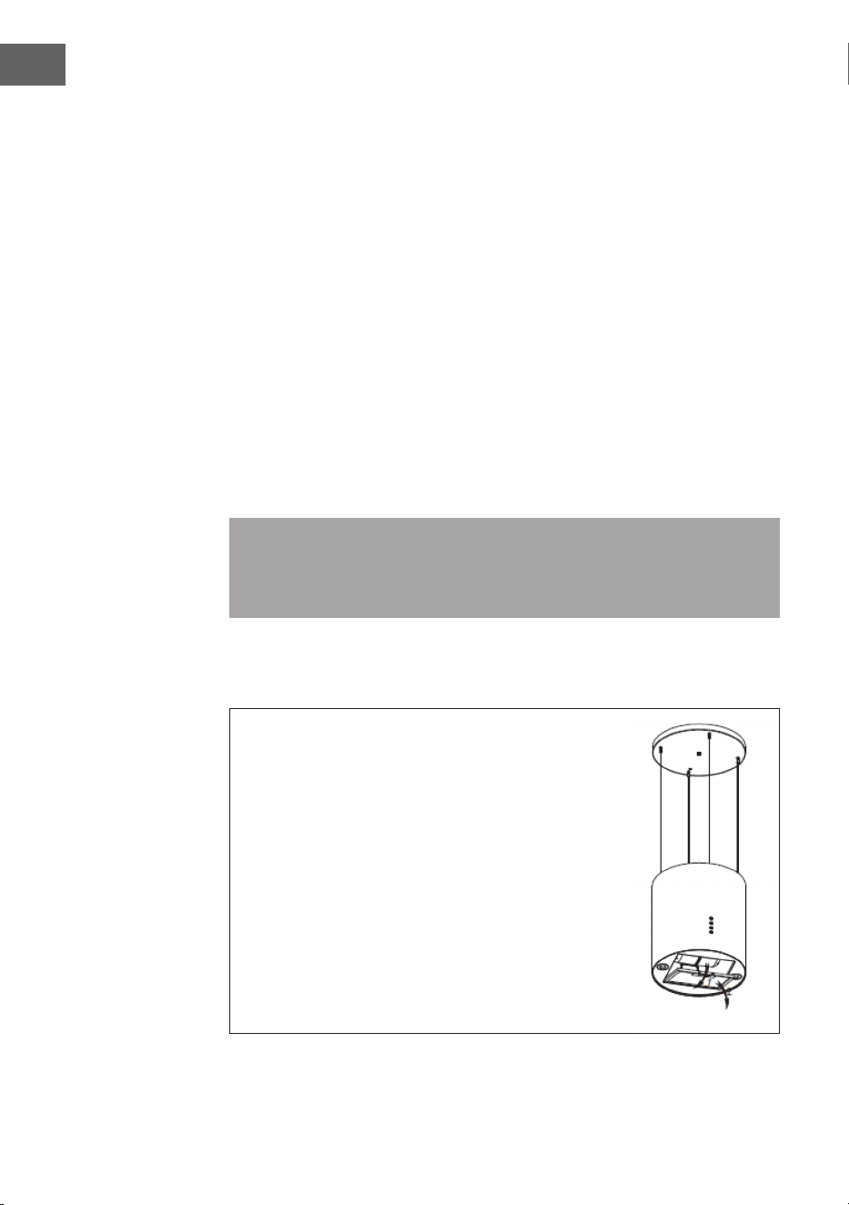
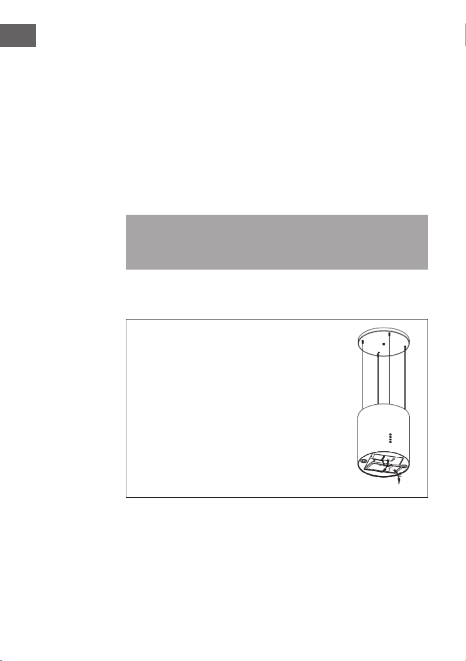
Installation
Wenn Sie einen Luftauslass nach außen haben, kann
die Dunstabzugshaube, wie rechts abgebildet, über
einen Absaugkanal (Emaille, Aluminium, exibles
Rohr oder unbrennbares Material mit einem
Innendurchmesser von 150 mm) angeschlossen
werden.
1 Ziehen Sie vor der Installation den Stecker aus der Steckdose
2
Die Dunstabzugshaube sollte in einem Abstand von 65-75 cm über der
Kochäche angebracht werden, um bestmögliche Wirkung zu erzielen.
7
DE
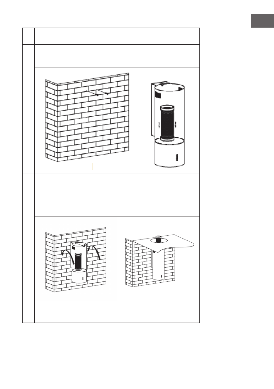
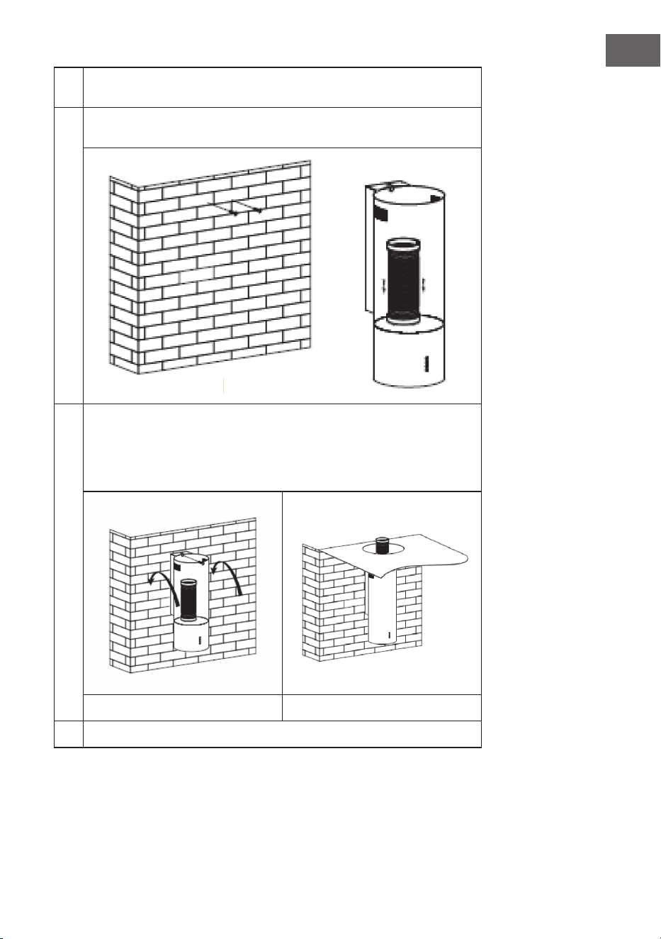
3
Bohren Sie 3 Löcher (Ø 8 mm) an einer geeigneten Stelle
der Wand, sobald die Installationshöhe festgelegt ist.
4
Setzen Sie die Dübel in die Löcher, schrauben Sie die
2 Schrauben ST4*30 mm halb in die Dübel, um den
Haubenkörper zu befestigen (siehe Bild).
5
Montieren Sie die V-Klappe und das Expansionsrohr auf die
Dunstabzugshaube und xieren Sie das Expansionsrohr mit einem
Kabelbinder (siehe Bild A). Hängen Sie die Dunstabzugshaube an den
Schrauben auf, und befestigen Sie das Gehäuse mit 1 Sicherheitsschraube
ST4*30 mm. Hinweis: Die beiden Sicherheitsentlüftungen (Durchmesser
von 6 mm) benden sich am hinteren Gehäuse (siehe Bild B).
A B
6
Führen Sie abschließend das Expansionsrohr nach außen.
8
DE
HINWEISE FÜR DEN EINBAU DES
ABLUFTROHRS
Die folgenden Regeln müssen strikt eingehalten werden, um eine optimale
Luftabsaugung zu erreichen:
• Achten Sie darauf, dass das Abluftrohr möglichst kurz und gerade verläuft.
• Verkleinern Sie die Größe nicht und schränken das Abluftrohr nicht ein.
Bei Verwendung von Abluftrohren ist das Rohr immer straff zu verlegen, um
den Druckverlust zu minimieren.
• Bei Nichtbeachtung dieser grundlegenden Anweisungen wird die Leistung
reduziert und der Geräuschpegel der Dunstabzugshaube erhöht.
• Alle Installationsarbeiten müssen von einer Elektrofachkraft oder einer dafür
qualizierten Person durchgeführt werden.
• Schließen Sie das Abluftrohr der Haube nicht an ein vorhandenes
Lüftungssystem an, das für ein anderes Gerät verwendet wird, z. B. einen
Rauchabzug, Gasrohre oder Heißluftrohre.
• Sofern das Abluftrohr einen Bogen macht, sollte der Winkel des Abluftrohrs
nicht kleiner als 120° sein. Richten Sie das Abluftrohr niemals nach unten,
sondern immer waagerecht aus oder führen Sie das Rohr vom Anfangspunkt
nach oben zum Luftauslass an der Außenwand.
• Nach dem Einbau ist darauf zu achten, dass die Dunstabzugshaube
waagerecht hängt, damit sich kein Fett ansammeln kann.
• Vergewissern Sie sich, dass das für die Installation ausgewählte Abluftrohr
den einschlägigen Normen entspricht und feuerabweisend ist.
VORSICHT
Verletzungsgefahr! Verwenden Sie aus Sicherheitsgründen nur die
in dieser Betriebsanleitung empfohlene Größe für Befestigungs-
oder Montageschraube. Die Nichtbeachtung dieser Anleitung kann
zu Verletzungen und Stromschlägen führen.
9
DE
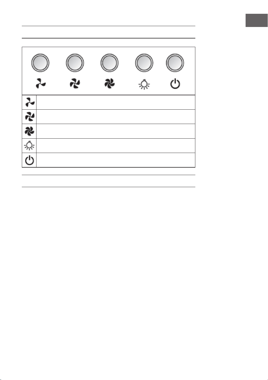
BEDIENFELD
Taste NIEDRIG (niedrige Lüfter-Geschwindigkeit)
Taste MITTEL (mittlere Lüfter-Geschwindigkeit)
Taste HOCH (Hohe Lüfter-Geschwindigkeit)
Taste LICHT (Licht ein/aus)
TASTE POWER (Dunstabzugshaube ein/aus)
BEDIENUNG
1. Wenn Sie den Netzstecker in die Steckdose stecken, leuchten alle
Leuchtanzeigen auf. Das Gerät wird in den Standbymodus versetzt. Wenn
keine Taste gedrückt wird, geht die Leuchtanzeige automatisch aus.
2. Einschalten: Wenn Sie einmal die Taste POWER drücken, leuchtet die
Leuchtanzeige auf und die Dunstabzugshaube läuft mit langsamer
Geschwindigkeit. Die Leuchtanzeige der Taste NIEDRIG ist an. Wenn Sie die
Taste POWER erneut drücken, wird das Gerät ausgeschaltet. Alle Funktionen
werden beendet und das Gerät wird in den Standbymodus versetzt. Die
Geschwindigkeitstasten und die Taste LICHT können unabhängig von der
Taste POWER verwendet werden. Wenn eine bestimmte Funktionstaste
gedrückt wird, dann wird die Dunstabzugshaube in den entsprechenden
Modus versetzt. Wenn Sie die Taste POWER in einem beliebigen Modus
drücken, wird das Gerät ausgeschaltet und alle Funktionen werden beendet.
3. Wenn Sie die Taste LICHT einmal drücken, wird das Licht eingeschaltet. Die
Anzeigeleuchte der Taste LICHT und die Anzeigeleuchte der Taste POWER
leuchten auf. Drücken Sie die Taste LICHT erneut, um das Licht auszuschalten.
Die Anzeigeleuchte der Taste LICHT und die Anzeigeleuchte der Taste POWER
gehen aus.

10
DE
4. Wenn Sie die Taste HOCH einmal drücken, läuft der Motor mit schneller
Geschwindigkeit und die Anzeigeleuchten der Taste HOCH und der Taste
POWER leuchten auf. Wenn Sie die Taste HOCH erneut drücken, wird der
Motor gestoppt. Die Anzeigeleuchten der Taste HOCH und der Taste POWER
gehen aus.
5. Wenn Sie die Taste MITTEL einmal drücken, läuft der Motor mit mittlerer
Geschwindigkeit und die Anzeigeleuchten der Taste MITTEL und der Taste
POWER leuchten auf. Wenn Sie die Taste MITTEL erneut drücken, wird der
Motor gestoppt. Die Anzeigeleuchten der Taste MITTEL und der Taste POWER
gehen aus.
6. Wenn Sie die Taste NIEDRIG einmal drücken, läuft der Motor mit langsamer
Geschwindigkeit und die Anzeigeleuchten der Taste NIEDRIG und der Taste
POWER leuchten auf. Wenn Sie die Taste NIEDRIG erneut drücken, wird
der Motor gestoppt. Die Anzeigeleuchten der Taste NIEDRIG und der Taste
POWER gehen aus.
7. Es kann immer nur eine Geschwindigkeit eingestellt werden. Zwei
Geschwindigkeitseinstellungen zur gleichen Zeit sind nicht möglich.
Wenn die Dunstabzugshaube mit schneller Geschwindigkeit läuft und
Sie die Taste NIEDRIG drücken, wechselt die Dunstabzugshaube zu
langsamer Geschwindigkeit. Wenn die Dunstabzugshaube mit langsamer
Geschwindigkeit läuft und Sie die Taste MITTEL drücken, wechselt die
Dunstabzugshaube sofort zu mittlerer Geschwindigkeit und so weiter.
11
DE
FEHLERSUCHE UND FEHLERBEHEBUNG
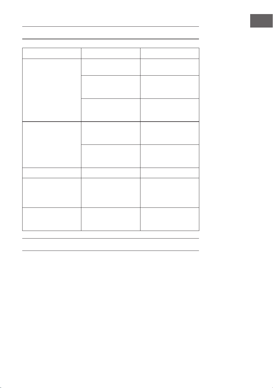
Fehler Mögliche Ursache Lösungsansatz
Das Licht geht an aber
der Motor läuft nicht.
Der Motor ist
ausgeschaltet.
Schalten Sie den
Motor mit der Taste
GESCHWINDIGKEIT ein.
Der Motorschalter
ist kaputt.
Kontaktieren Sie
einen Fachbetrieb.
Der Motor ist kaputt. Kontaktieren Sie
einen Fachbetrieb.
Licht und Motor
funktionieren nicht.
Ihre Haus-Sicherung ist
umgelegt oder kaputt.
Legen Sie den
Sicherungsschalter
um oder ersetzen
Sie die Sicherung
Das Netzkabel ist lose
oder nicht verbunden.
Schließen Sie das
Netzkabel richtig an.
Das Licht geht nicht. Das Licht ist kaputt. Ersetzen Sie die Lampe.
Unbefriedigende
Absaugleistung
Der Abstand zwischen
Herd und Abzugshaube
ist zu groß.
Verringern Sie
den Abstand.
Die Abzugshaube
hängt schief.
Eine der Fixierschrauben
ist nicht richtig
angezogen.
Ziehen Sie die
Schraube fest an.
REINIGUNG UND PFLEGE
Vor der Wartung oder Reinigung sollte die Dunstabzugshaube immer vom
Stromnetz getrennt werden. Stellen Sie sicher, dass die Dunstabzugshaube
ausgeschaltet ist und der Stecker entfernt wurde. Äußere Oberächen sind
anfällig für Kratzer und Dellen, beachten Sie daher die Reinigungshinweise, um ein
bestmögliches Ergebnis ohne Beschädigung zu erzielen.
Allgemein
Lassen Sie das Gerät vor der Reinigung und Pege komplett abkühlen und
verwenden Sie zur Reinigung der Oberäche keine alkalischen oder saure
Substanzen, wie Zitronensaft oder Essig.
12
DE
Edelstahl
Der Edelstahl muss regelmäßig (wöchentlich) gereinigt werden, um eine
lange Lebensdauer zu gewährleisten. Dafür kann eine spezielle Edelstahl-
Reinigungsüssigkeit verwendet werden.
Bedienfeld
Das Bedienfeld kann mit warmem Seifenwasser gereinigt werden. Stellen Sie
sicher, dass das Tuch sauber und gut ausgewrungen ist, bevor Sie as Bedienfeld
reinigen. Verwenden Sie ein trockenes, weiches Tuch, um überschüssige
Feuchtigkeit nach der Reinigung zu entfernen.
Wichtig: Verwenden Sie neutrale Reinigungsmittel und vermeiden Sie die
Verwendung von scharfen Reinigungschemikalien, starken Haushaltsreinigern
oder Produkten, die Scheuermittel enthalten, da dies das Aussehen des Geräts
beeinträchtigt und möglicherweise die gedruckten Symbole auf dem Bedienfeld
entfernt.
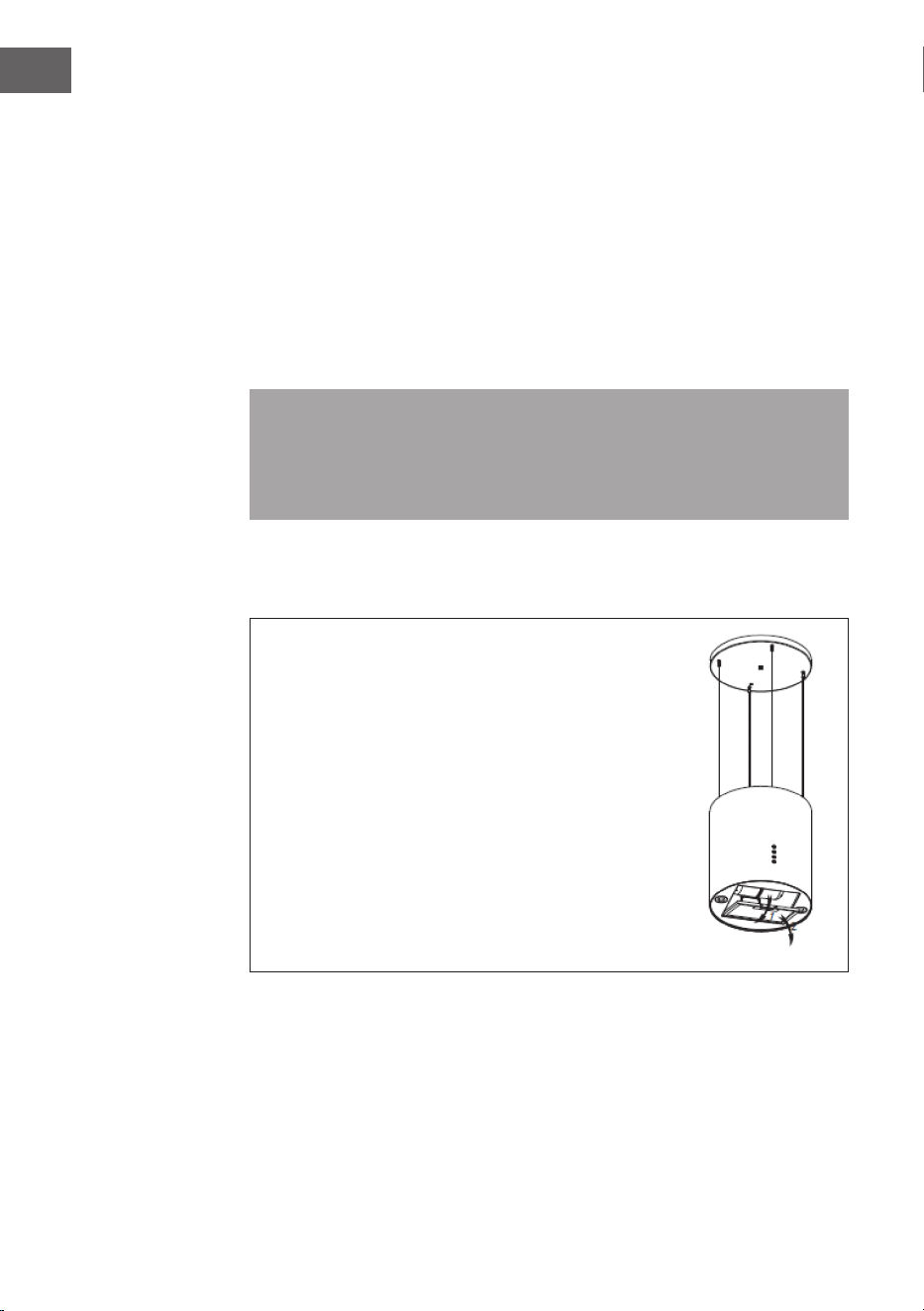
Fettlter
Die Gewebelter können von Hand gereinigt werden.
Weichen Sie sie zusammen mit einem fettlösenden
Reinigungsmittel ca. 3 Minuten in Wasser ein und
bürsten Sie sie dann mit einer weichen Bürste sanft ab.
Üben Sie nicht zu viel Druck aus, um den Filter nicht
zu beschädigen. Lassen Sie den Filter danach an der
Luft trocknen, legen Sie ihn aber nicht direkt in die
Sonne. Filter sollten immer getrennt von Geschirr und
Küchenutensilien gewaschen werden!
Entfernen Sie den Filter wie rechts auf dem
Bild dargestellt und setzen Sie ihn dann in
umgekehrter Reihenfolge wieder ein.
13
DE
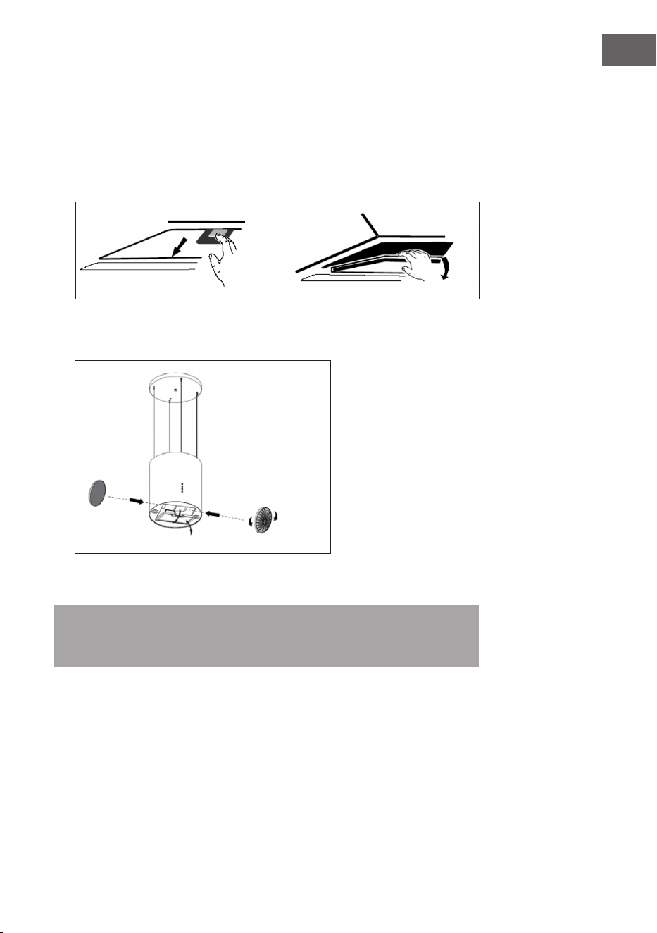
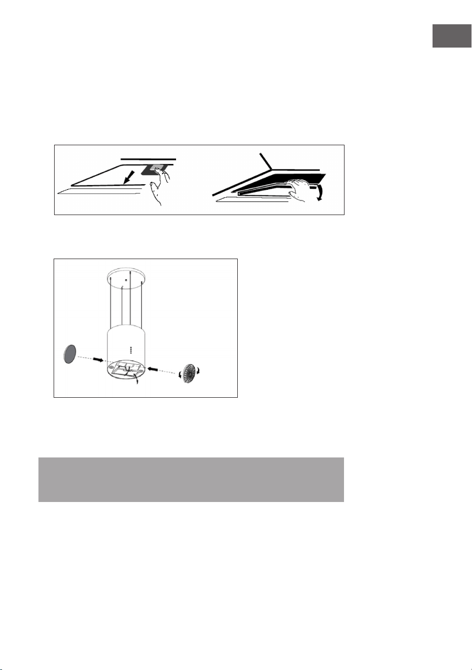
Aktivkohlelter
Aktivkohlelter können zum Entfernen von Gerüchen verwendet werden.
Normalerweise sollte der Aktivkohlelter je nach Kochgewohnheit nach drei
oder sechs Monaten gewechselt werden. Der Einbau des Aktivkohlelters erfolgt
folgendermaßen:
1. Trennen Sie die Abzugshaube vor dem Einbau vom Stromnetz.
2. Drücken Sie den Filterverschluss und entfernen Sie den Netzlter.
3. Drehen Sie den Kohlelter auf beiden Seiten des Motors gegen den
Uhrzeigersinn. Ersetzen Sie die alten Kohlelter durch neue Kohlelter.
4. Setzen Sie den Netzlter wieder ein.
5. Schließen Sie den Netzstecker wieder an die Steckdose an.
Hinweis: Vergewissern Sie sich, dass der Filter fest verschlossen ist. Andernfalls
kann es sich lösen und gefährlich werden. Bei angeschlossenem Aktivkohlelter
wird die Saugleistung verringert.
öffnen
schließen
14
DE
Lampe auswechseln
• Die Lampe muss vom Hersteller, seinem Kundendienst oder ähnlich
qualizierten Personen ausgetauscht werden.
• Schalten Sie immer die Stromzufuhr ab, bevor Sie irgendwelche Arbeiten am
Gerät durchführen. Achten Sie beim Umgang mit der Lampe darauf, dass sie
vollständig abgekühlt ist, bevor Sie sie direkt mit den Händen berühren.
• Halten Sie die Lampe beim Einsetzen oder Ausbauen immer mit einem Tuch
oder Handschuhen fest, um sicherzustellen, dass ein Schweiß mit der Lampe
in Berührung kommt, da dies die Lebensdauer verringern kann.
So tauschen Sie die Lampe aus:
1. Vergewissern Sie sich vor dem Wechsel der Beleuchtung, dass die
Dunstabzugshaube ausgeschaltet ist.
2. Drehen Sie die Abdeckung gegen den Uhrzeigersinn. Lösen Sie die Schraube
des Edelstahllters und entfernen Sie ihn.
3. Drücken Sie den Anschluss der Lampe, um die Lampe zu entfernen.
4. Montieren Sie die neue Lampe und schließen Sie das Kabel wieder an.
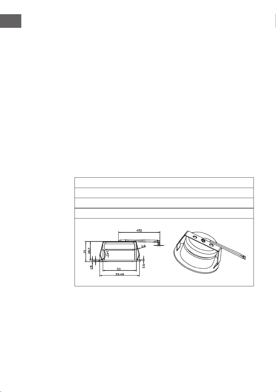
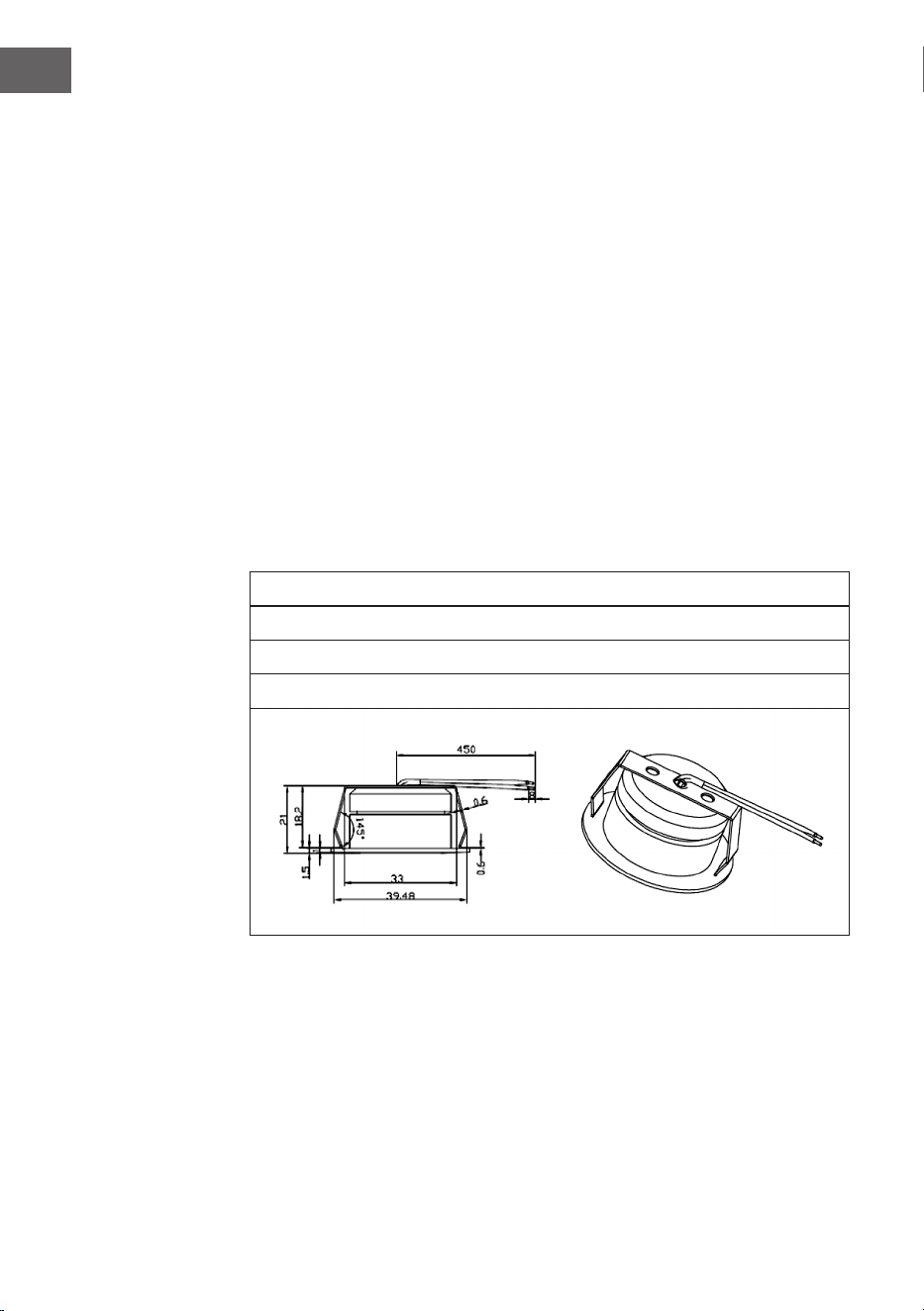
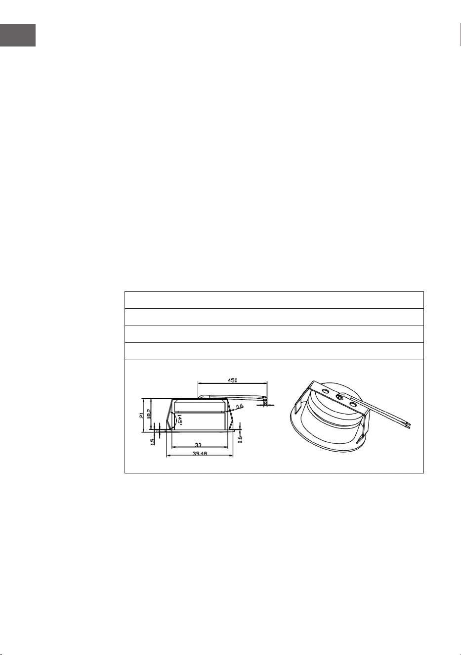
Wichtige Informationen zum Leuchtmittel
LED-Typ: Runde Glaslampe
Maximale Wattzahl: 2 x 1 W
Spannungsbereich: 12 V
Abmessungen: siehe Abbildung

15
DE
HINWEISE ZUM UMWELTSCHUTZ
• Achten Sie während des Kochens auf eine ausreichende Luftzufuhr, damit die
Dunstabzugshaube ezient und mit einem geringen Betriebsgeräusch arbeiten
kann.
• Passen Sie die Gebläsedrehzahl an die beim Kochen entstehende
Dampfmenge an. Verwenden Sie den Intensivmodus nur bei Bedarf. Je
niedriger die Gebläsedrehzahl ist, desto weniger Energie wird verbraucht.
• Wenn beim Garen große Mengen Dampf entstehen, wählen Sie rechtzeitig
eine höhere Gebläsedrehzahl. Wenn sich der Kochdampf bereits in der Küche
verteilt hat, muss die Dunstabzugshaube länger betrieben werden.
• Schalten Sie die Dunstabzugshaube aus, wenn Sie sie nicht mehr benötigen.
• Schalten Sie die Beleuchtung aus, wenn Sie diese nicht mehr benötigen.
• Reinigen Sie den Filter in regelmäßigen Abständen und tauschen Sie ihn ggf.
aus, um die Effektivität des Lüftungssystems zu erhöhen und Brandgefahr zu
vermeiden.
• Setzen Sie beim Kochen immer den Deckel auf, um Kochdampf und
Kondenswasser zu reduzieren.
16
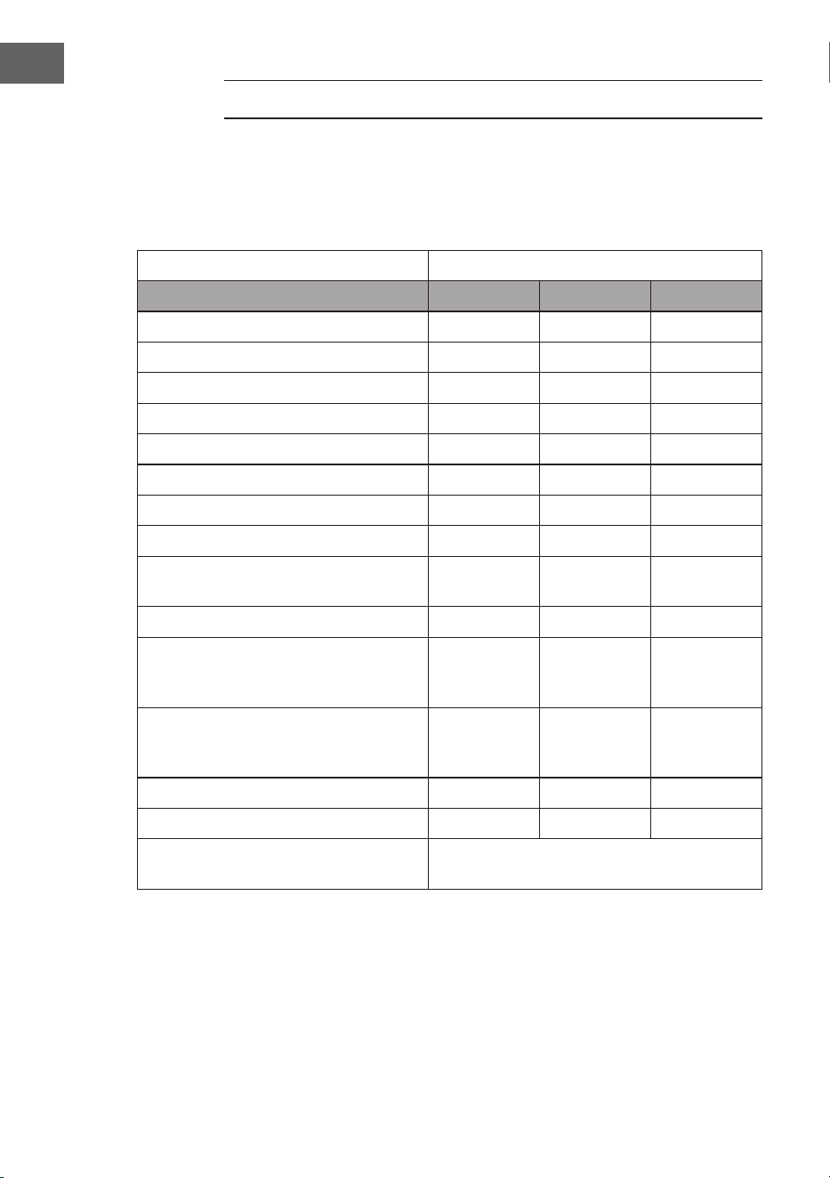
DE
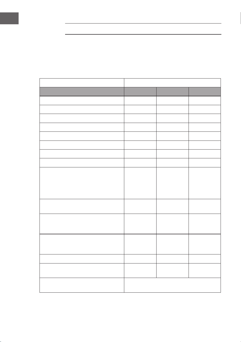
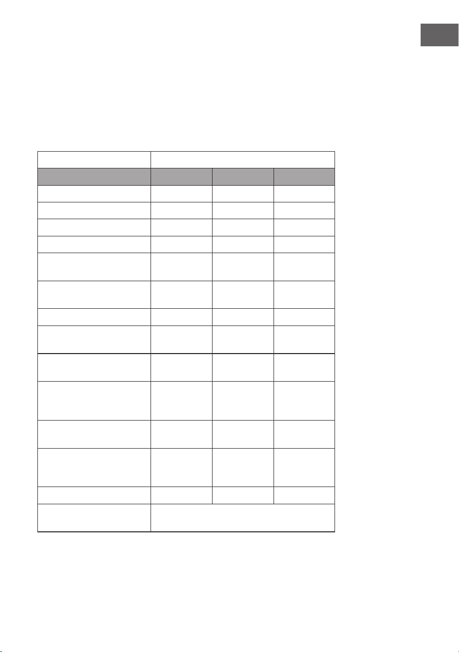
PRODUKTDATENBLATT
Angaben nach Verordnung (EU) Nr. 65/2014
Mess- und Berechnungsmethoden nach EN 61591:1997+A1:2006+A2:2011+A11:20
14+A12:2015
Artikelnummer 10037863, 10037864, 10037865
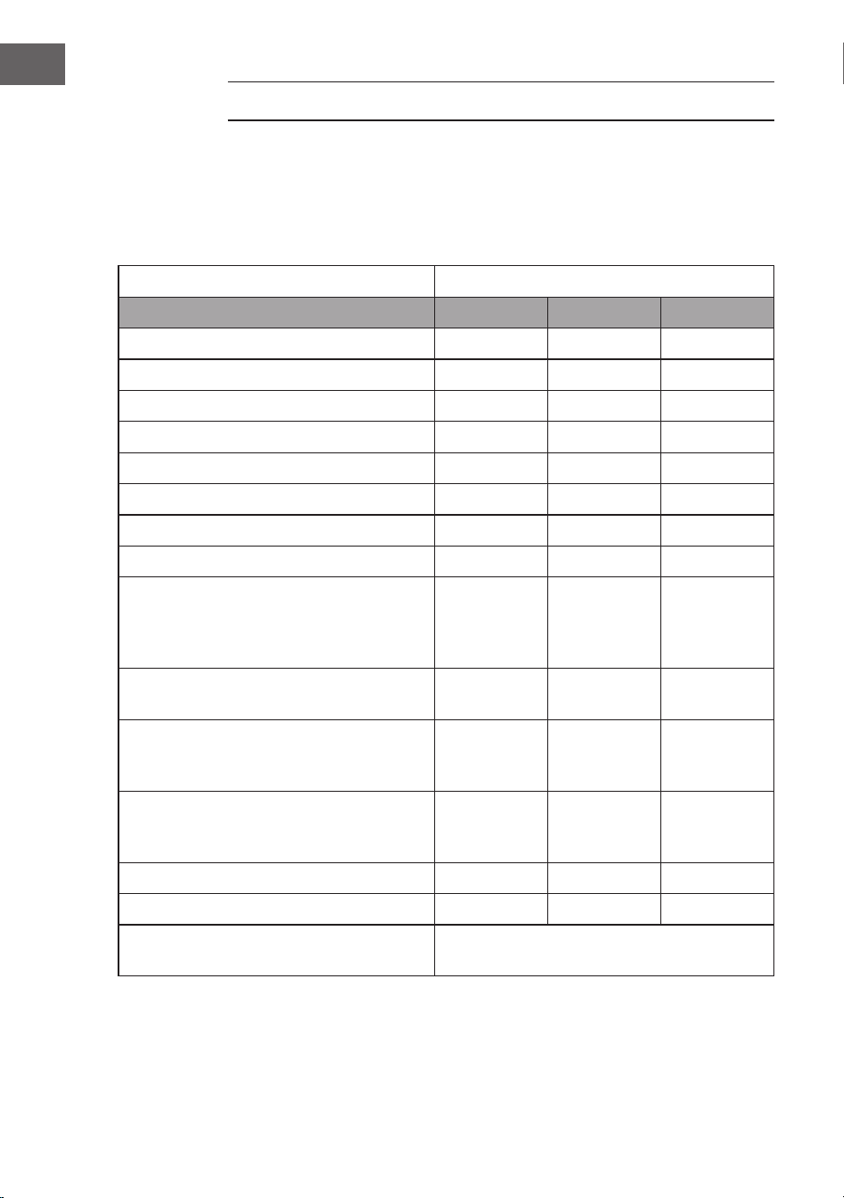
Bezeichnung Symbol Wert Einheit
Jährlicher Energieverbrauch AEC
hood
16,3 kWh/Jahr
Energieezienzklasse A+
uiddynamische Ezienz FDE
hood
26,6
Klasse für die uiddynamische Ezienz B
Beleuchtungsezienz LE
hood
95,4 Lux/W
Beleuchtungsezienzklasse A
Fettabscheidegrad GFE
hood
83,7 %
Klasse für den Fettabscheidegrad C
Luftstrom bei minimaler und bei
maximaler Geschwindigkeit im
Normalbetrieb, ausgenommen den
Betrieb auf der Intensivstufe oder
Schnelllaufstufe
188 / 518 m³/h
Luftstrom im Betrieb auf der
Intensivstufe oder Schnelllaufstufe
- m³/h
A-bewertete Luftschallemissionen bei
minimaler und maximaler verfügbarer
Geschwindigkeit im Normalbetrieb
42 / 65 dB
A-bewertete Luftschallemissionen
im Betrieb auf der Intensivstufe oder
Schnelllaufstufe
- dB
Leistungsaufnahme im Aus-Zustand P
o
- W
Leistungsaufnahme im
Bereitschaftszustand
P
s
0,48 W
Kontaktangaben Chal-Tec GmbH, Wallstraße 16,
10179, Berlin, Deutschland
17
DE
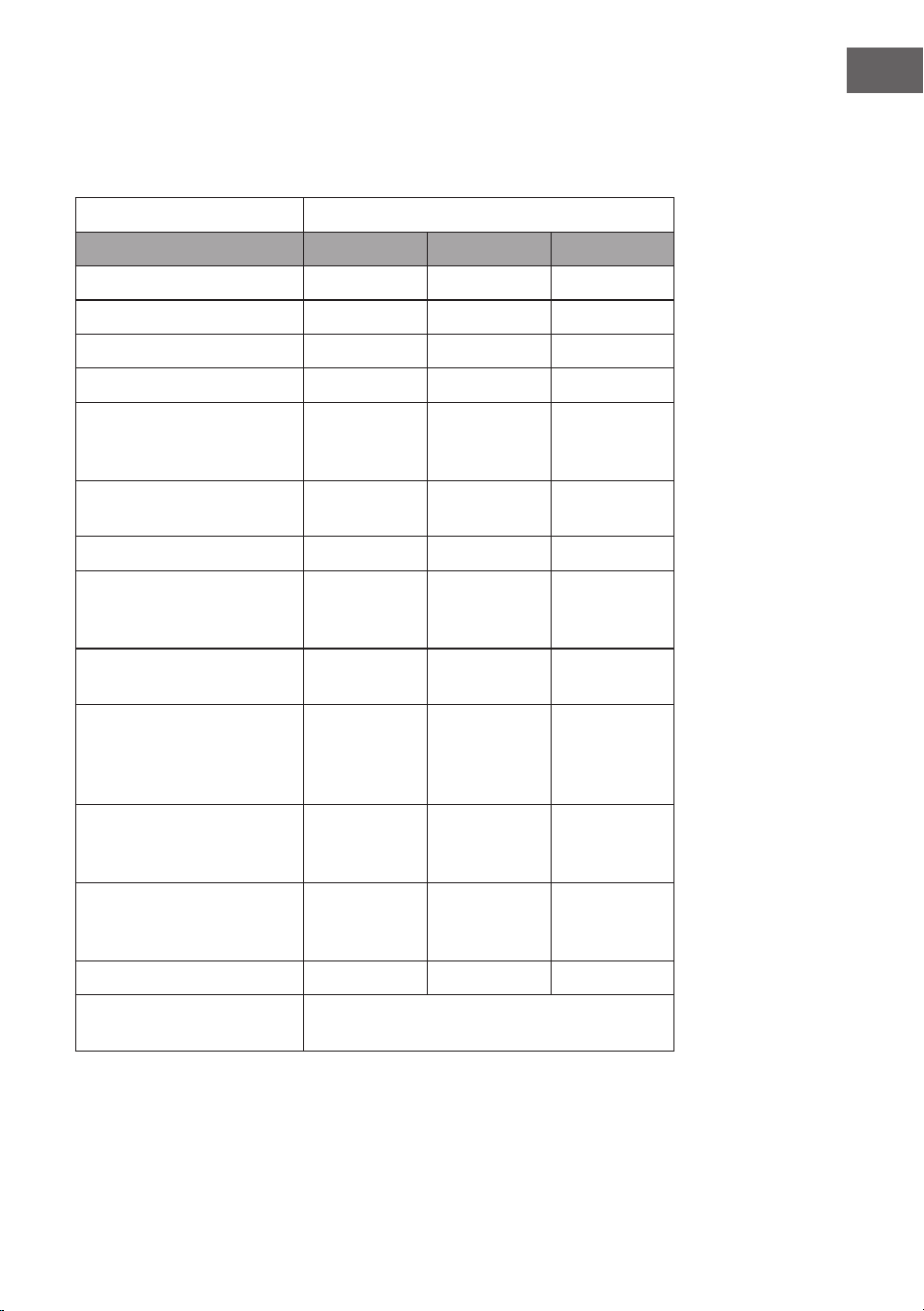
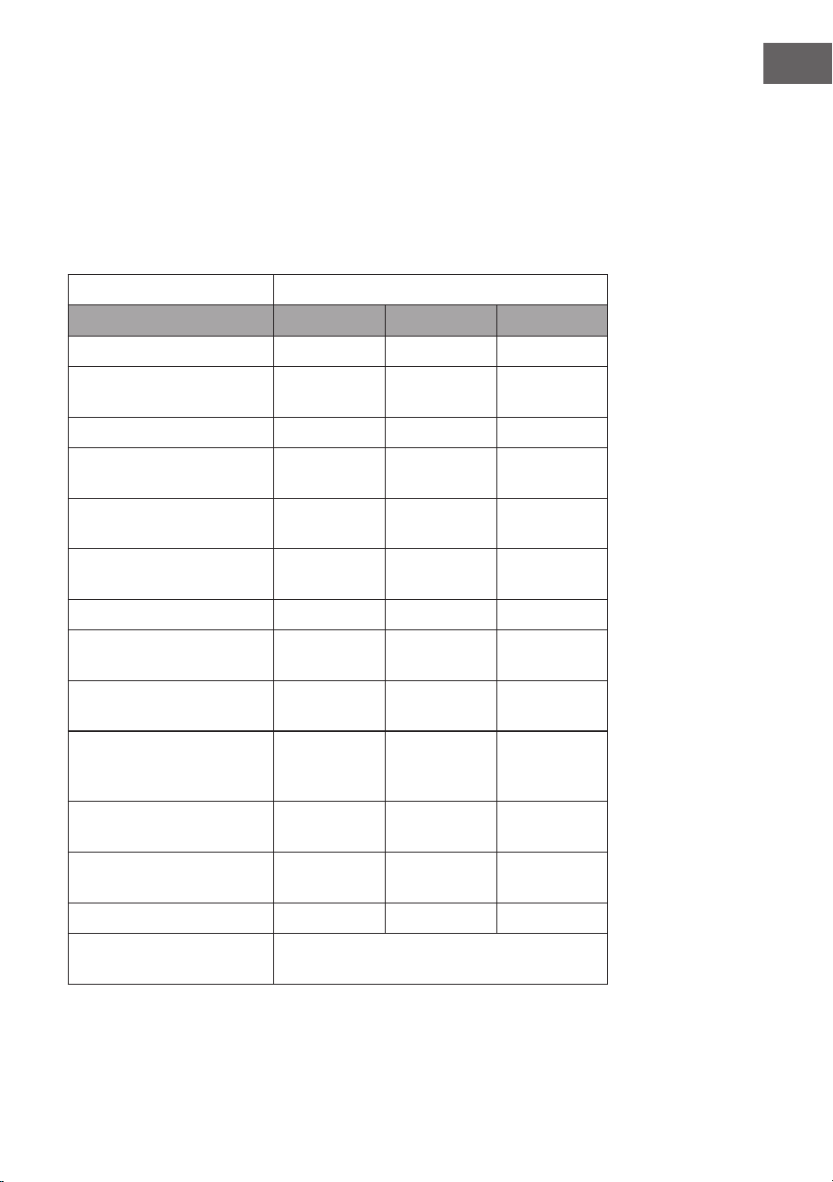
Angaben nach Verordnung (EU) Nr. 66/2014
Mess- und Berechnungsmethoden nach EN 61591:1997+A1:2006+A2:2011+A11:20
14+A12:2015
Artikelnummer 10037863, 10037864, 10037865
Bezeichnung Symbol Wert Einheit
Jährlicher Energieverbrauch AEC
hood
16,3 kWh/Jahr
Zeitverlängerungsfaktor f 1,0
Fluiddynamische Ezienz FDE
hood
26,6
Energieezienzindex EEI
hood
43,1
Gemessener
Luftvolumenstrom im
Bestpunkt
Q
BEP
174,9 m³/h
Gemessener Luftdruck im
Bestpunkt
P
BEP
204 Pa
Maximaler Luftstrom Q
max
518 m³/h
Gemessene elektrische
Eingangsleistung im
Bestpunkt
W
BEP
37,3 W
Nennleistung des
Beleuchtungssystems
W
L
3,7 W
Durchschnittliche
Beleuchtungsstärke des
Beleuchtungssystems auf
der Kochoberäche
E
middle
352,8 Lux
Gemessene
Leistungsaufnahme im Aus-
Zustand
P
o
- W
Gemessene
Leistungsaufnahme im
Bereitschaftszustand
P
s
0,48 W
Schallleistungspegel L
WA
42 / 65 dB
Kontaktangaben Chal-Tec GmbH, Wallstraße 16,
10179, Berlin, Deutschland
18
DE
SPEZIELLE ENTSORGUNGSHINWEISE FÜR
VERBRAUCHER IN DEUTSCHLAND
Entsorgen Sie Ihre Altgeräte fachgerecht. Dadurch wird gewährleistet, dass die
Altgeräte umweltgerecht verwertet und negative Auswirkungen auf die Umwelt
und menschliche Gesundheit vermieden werden. Bei der Entsorgung sind
folgende Regeln zu beachten:
• Jeder Verbraucher ist gesetzlich verpichtet, Elektro- und
Elektronikaltgeräte (Altgeräte) sowie Batterien und Akkus
getrennt vom Hausmüll zu entsorgen. Sie erkennen die
entsprechenden Altgeräte durch folgendes Symbol der
durchgestrichenen Mülltonne (WEEE-Symbol).
• Sie haben Altbatterien und Altakkumulatoren, die nicht vom Altgerät
umschlossen sind, sowie Lampen, die zerstörungsfrei aus dem Altgerät
entnommen werden können, vor der Abgabe an einer Entsorgungsstelle vom
Altgerät zerstörungsfrei zu trennen.
• Bestimmte Lampen und Leuchtmittel fallen ebenso unter das Elektro- und
Elektronikgesetz und sind dementsprechend wie Altgeräte zu behandeln.
Ausgenommen sind Glühbirnen und Halogenlampen. Entsorgen Sie
Glühbirnen und Halogenlampen bitte über den Hausmüll, sofern sie nicht das
WEEE-Symbol tragen.
• Jeder Verbraucher ist für das Löschen von personenbezogenen Daten auf dem
Elektro- bzw. Elektronikgerät selbst verantwortlich.
Rücknahmepicht der Vertreiber
Vertreiber mit einer Verkaufsäche für Elektro- und Elektronikgeräte von
mindestens 400 Quadratmetern sowie Vertreiber von Lebensmitteln mit einer
Gesamtverkaufsäche von mindestens 800 Quadratmetern, die mehrmals im
Kalenderjahr oder dauerhaft Elektro- und Elektronikgeräte anbieten und auf dem
Markt bereitstellen, sind verpichtet,
1. bei der Abgabe eines neuen Elektro- oder Elektronikgerätes an einen Endnutzer
ein Altgerät des Endnutzers der gleichen Geräteart, das im Wesentlichen die
gleichen Funktionen wie das neue Gerät erfüllt, am Ort der Abgabe oder in
unmittelbarer Nähe hierzu unentgeltlich zurückzunehmen und
2. auf Verlangen des Endnutzers Altgeräte, die in keiner äußeren Abmessung
größer als 25 Zentimeter sind, im Einzelhandelsgeschäft oder in unmittelbarer
Nähe hierzu unentgeltlich zurückzunehmen; die Rücknahme darf nicht an den
Kauf eines Elektro- oder Elektronikgerätes geknüpft werden und ist auf drei
Altgeräte pro Geräteart beschränkt.

19
DE
• Bei einem Vertrieb unter Verwendung von Fernkommunikationsmitteln
ist die unentgeltliche Abholung am Ort der Abgabe auf Elektro- und
Elektronikgeräte der Kategorien 1, 2 und 4 gemäß § 2 Abs. 1 ElektroG, nämlich
„Wärmeüberträger“, „Bildschirmgeräte“ (Oberäche von mehr als 100 cm²)
oder „Großgeräte“ (letztere mit mindestens einer äußeren Abmessung
über 50 Zentimeter) beschränkt. Für andere Elektro- und Elektronikgeräte
(Kategorien 3, 5 und 6) ist eine Rückgabemöglichkeit in zumutbarer
Entfernung zum jeweiligen Endnutzer zu gewährleisten.
• Altgeräte dürfen kostenlos auf dem lokalen Wertstoffhof oder in folgenden
Sammelstellen in Ihrer Nähe abgegeben werden: www.take-e-back.de
• Für Elektro- und Elektronikgeräte der Kategorien 1, 2 und 4 bieten wir auch
die Möglichkeit einer unentgeltlichen Abholung am Ort der Abgabe an. Beim
Kauf eines Neugeräts haben Sie die Möglichkeit, eine Altgerätabholung über
die Webseite auszuwählen.
• Batterien können überall dort kostenfrei zurückgegeben werden, wo sie
verkauft werden (z. B. Super-, Bau-, Drogeriemarkt). Auch Wertstoff- und
Recyclinghöfe nehmen Batterien zurück. Sie können Batterien auch per Post
an uns zurücksenden. Altbatterien in haushaltsüblichen Mengen können Sie
direkt bei uns von Montag bis Freitag zwischen 08:00 und 16:00 Uhr unter der
folgenden Adresse unentgeltlich zurückgeben:
Chal-Tec Fulllment GmbH
Norddeutschlandstr. 3
47475 Kamp-Lintfort
• Wichtig zu beachten ist, dass Lithiumbatterien aus Sicherheitsgründen vor der
Rückgabe gegen Kurzschluss gesichert werden müssen (z. B. durch Abkleben
der Pole).
• Finden sich unter der durchgestrichenen Mülltonne auf der Batterie zusätzlich
die Zeichen Cd, Hg oder Pb ist das ein Hinweis darauf, dass die Batterie
gefährliche Schadstoffe enthält. (»Cd« steht für Cadmium, »Pb« für Blei und
»Hg« für Quecksilber.)
Hinweis zur Abfallvermeidung
Indem Sie die Lebensdauer Ihrer Altgeräte verlängern, tragen Sie dazu bei,
Ressourcen ezient zu nutzen und zusätzlichen Müll zu vermeiden. Die
Lebensdauer Ihrer Altgeräte können Sie verlängern, indem Sie defekte Altgeräte
reparieren lassen. Wenn sich Ihr Altgerät in gutem Zustand bendet, könnten Sie
es spenden, verschenken oder verkaufen.
20
DE
HINWEISE ZUR ENTSORGUNG
Wenn es in Ihrem Land eine gesetzliche Regelung
zur Entsorgung von elektrischen und elektronischen
Geräten gibt, weist dieses Symbol auf dem Produkt oder
auf der Verpackung darauf hin, dass dieses Produkt
nicht im Hausmüll entsorgt werden darf. Stattdessen
muss es zu einer Sammelstelle für das Recycling von
elektrischen und elektronischen Geräten gebracht
werden. Durch regelkonforme Entsorgung schützen
Sie die Umwelt und die Gesundheit Ihrer Mitmenschen
vor negativen Konsequenzen. Informationen zum
Recycling und zur Entsorgung dieses Produkts,
erhalten Sie von Ihrer örtlichen Verwaltung oder Ihrem
Hausmüllentsorgungsdienst.
HERSTELLER & IMPORTEUR (UK)
Hersteller:
Chal-Tec GmbH, Wallstraße 16, 10179 Berlin, Deutschland.
Importeur für Großbritannien:
Berlin Brands Group UK Limited
PO Box 42
272 Kensington High Street
London, W8 6ND
United Kingdom

21
EN
Dear Customer,
Congratulations on purchasing this device. Please read the
following instructions carefully and follow them to prevent
possible damages. We assume no liability for damage
caused by disregard of the instructions and improper use.
Scan the QR code to get access to the latest user manual
and more product information.
CONTENTS
Safety Instructions 22
Installation (External Ventilation) 24
Instructions for Installing the Exhaust Pipe 26
Control Panel 27
Operation 27
Troubleshooting 29
Cleaning and Care 29
Notes on Environmental Protection 33
Product Data Sheet 34
Disposal Considerations 36
Manufacturer & Importer (UK) 36
TECHNICAL DATA
Item number 10037863, 10037864, 10037865
Power supply 220-240 V ~ 50 Hz

22
EN
SAFETY INSTRUCTIONS
• Thank you for purchasing this cooker hood. Please read the instruction
manual carefully before you use the cooker hood, and keep it in a safe place.
• The installation work must be carried out by a qualied electrician or compe-
tent person. Before you use the cooker hood, make sure that the voltage (V)
and the frequency (Hz) indicated on the cooker hood are exactly the same as
the voltage and the frequency in your home.
• The manufacturer and the agent will not bear any responsibility for the dam-
age caused by inappropriate installation and usage.
• Children under the age of 8 must not use the cooker hood.
• The appliance is not intended for commercial use, but only for household and
similar environments.
• The cooker hood and its lter mesh should be cleaned regularly in order to
keep it in good working order.
• Before cleaning, switch the power off at the main supply.
• Clean the cooker hood according to the instruction manual and keep the
cooker hood from the danger of burning.
• Prohibit putting the cooker hood by re.
• If the appliance does not function normally, contact the manufacturer or a
specialist company.
• This device may be only used by children 8 years old or older and persons with
limited physical, sensory and mental capabilities and / or lack of experience
and knowledge, provided that they have been instructed in use of the device
by a responsible person who understands the associated risks.
• If the supply cord is damaged, it must be replaced by the manufacturer, its
service agent or similarly qualied persons in order to avoid a hazard.
• If the range hood is used at the same time as appliances burning gas or other
fuels, the room must be adequately ventilated.
• Do not ambé under the range hood. Accessible parts may become hot when
used with cooking appliances.
Important hints on installation
• The air must not be discharged into a ue that is used for exhausting fumes
from appliances burning gas or other fuels (not applicable to appliances that
only discharge the air back into the room).
• Regulations concerning the discharge of air have to be fullled.

23
EN
Important notes about the extraction mode
WARNING
Risk of poisoning from exhaust gases sucked back. Never
operate the device in extraction mode simultaneously with an
open ue appliance when there is not adequate airow
guaranteed.
Open ue combustion equipment (for example, gas, oil, wood or coal-red
heaters, tankless water heaters, water heaters) pulls combustion air from the
room and runs it through an exhaust pipe or chimney to the outside. In the
extraction mode, indoor air is removed from the kitchen and the adjacent rooms
- without sucient air intake this creates a vacuum. Toxic gases from the chimney
or extraction ue can thereby be sucked back into the living spaces.
• Always ensure that a sucient supply of fresh air is guaranteed and that the
air can circulate.
• An air supply / extractor box alone does not ensure compliance with the limit
value.
Safe operation is only possible when the negative pressure in the room where the
appliance is located does not exceed 4 Pa (0.04 mbar). This can be achieved when
the air required for combustion can ow through openings that are not closable,
for example in doors, windows, in conjunction with an air supply / extractor box or
through other technical measures. In any case, consult a qualied chimney sweep
who can assess the entire ventilation of your house and propose appropriate
measures for adequate ventilation.
If the hood is used exclusively in the recirculation mode, unrestricted operation is
possible.
Important note on disassembly of the device
• Disassembly is similar to installation/assembly in reverse order.
• Take a second person to help you during disassembly to avoid injuries.
24
EN
INSTALLATION (EXTERNAL VENTILATION)
Assembly of the V-ap
If the cooker hood does not have a pre-assembled V-ap, install the parts as
follows:
1. Install the rst half (2) in the housing (6).
2. The pin (3) should be facing upwards.
3. Insert the axle (4) into the holes (5) on the housing.
4. Repeat all steps for the second half of the ap.
Installation
If you have an outside air outlet, the hood can be
connected via a suction duct (enamel, aluminum,
exible tube or non-ammable material with an
inside diameter of 150 mm) as shown on the right.
1 Remove the plug from the socket before installation.
2
The cooker hood should be placed at a distance of 65-75 cm
above the cooking surface for the best possible effect.
25
EN
3
Drill 3 holes (Ø 8 mm) in a suitable place on the wall
once the installation height is determined.
4
Place the dowels in the holes, screw the 2 screws ST4*30 mm
halfway into the dowels to x the canopy body (see picture).
5
Mount the V-ap and the expansion tube on the cooker hood
and x the expansion tube with a cable tie (see picture A).
Hang the cooker hood on the screws and x the housing with 1
safety screw ST4*30 mm. Note: The two safety vents (diameter
of 6 mm) are located on the rear housing (see picture B).
A B
6
Finally, guide the expansion tube to the outside.
26
EN
INSTRUCTIONS FOR INSTALLING
THE EXHAUST PIPE
The following rules must be strictly adhered to in order to achieve optimal air
extraction:
• Make sure that the exhaust pipe is as short and straight as possible.
• Do not reduce the size and do not restrict the exhaust pipe. When using
exhaust pipes, the pipe must always be laid tightly in order to minimize the
pressure loss.
• Failure to follow these basic instructions will reduce performance and increase
the noise level of the cooker hood.
• All installation work must be carried out by a qualied electrician or other
qualied person.
• Do not connect the exhaust pipe of the hood to an existing ventilation system
that is used for another unit, such as a ventilation system, such as a ue, gas
pipes or hot air pipes.
• If the exhaust pipe makes a bend, the angle of the exhaust pipe should not be
less than 120 °. Never align the exhaust pipe downwards, but always align it
horizontally or guide the pipe from the starting point upwards to the air outlet
on the outer wall.
• After installation, make sure that the cooker hood is horizontal so that no
grease can accumulate.
• Make sure that the exhaust pipe selected for the installation complies with the
relevant standards and is re resistant.
CAUTION
Risk of injury. For safety reasons, use only the size of xing or
mounting screws recommended in this manual. Failure to follow
these instructions may result in injury or electric shock.

27
EN
CONTROL PANEL
LOW key (low fan speed)
MEDIUM button (medium fan speed)
HIGH key (high fan speed)
LIGHT button (light on/off)
POWER button (extractor hood on/off)
OPERATION
1. When you insert the mains plug into the socket, all the indicator lamps light
up. The device is put into standby mode. If no key is pressed, the indicator
light will turn off automatically.
2. Switching on: When you press the POWER button once, the indicator light
will turn on and the range hood will run at slow speed. The indicator light of
the LOW key is on. If you press the POWER key again, the appliance will be
switched off. All functions are terminated and the unit is set to standby mode.
The speed keys and the LIGHT key can be used independently of the POWER
key. If a specic function key is pressed, then the range hood will be set to the
corresponding mode. If you press the POWER key in any mode, the unit will be
turned off and all functions will be terminated.
3. If you press the LIGHT key once, the light will be turned on. The indicator light
of the LIGHT key and the indicator light of the POWER key will light up. Press
the LIGHT key again to turn the light off. The indicator light of the LIGHT key
and the indicator light of the POWER key go out.

28
EN
4. When you press the UP key once, the motor runs at a fast speed and the
indicator lights of the UP key and the POWER key light up. When you press the
HIGH key again, the motor stops. The indicator lights of the HIGH key and the
POWER key turn off. 5.
5. When you press the MEDIUM key once, the motor runs at medium speed and
the indicator lights of the MEDIUM key and the POWER key light up. When
you press the CENTER key again, the motor stops. The indicator lights of the
CENTER key and the POWER key go out. 6.
6. When you press the LOW key once, the motor runs at slow speed and the
indicator lights of the LOW key and the POWER key light up. When you press
the LOW key again, the motor stops. The indicator lights of the LOW key and
the POWER key go out. 7.
7. Only one speed can be set at a time. Two speed settings at the same time
are not possible. If the range hood is running at fast speed and you press
the LOW key, the range hood will change to slow speed. If the cooker hood
is running at slow speed and you press the MEDIUM key, the cooker hood
immediately changes to medium speed and so on.
29
EN
TROUBLESHOOTING
Problem Possible cause Solution
The light goes on but
the motor does not run.
The motor is
switched off.
Switch on the motor
with the SPEED button.
The motor switch
is broken.
Contact a specialist.
The motor is broken. Contact a specialist.
The light and the motor
are not working.
Your house fuse is
ipped or broken.
Replace the fuse switch
or replace the fuse.
The power cord is loose
or not connected.
Connect the power
cord properly.
The light does not work. The light is broken. Replace the bulb.
Unsatisfactory exhaust
performance.
The distance between
the stove and extractor
hood is too great.
Reduce the distance.
The hood is
hanging awry.
One of the xing
screws is not
tightened properly.
Tighten the screw
properly.
CLEANING AND CARE
Before servicing or cleaning, the cooker hood should always be disconnected
from the power supply. Make sure the cooker hood is off and the plug has been
removed. External surfaces are prone to scratches and dents, so follow the
cleaning instructions to get the best results without damage.
General
Allow the unit to cool completely before cleaning and caring for the device, and do
not use alkaline or acidic substances such as lemon juice or vinegar to clean the
surface.
30
EN
Stainless steel
The stainless steel must be cleaned regularly (weekly) to ensure a long service life.
For this, a special stainless steel cleaning uid may be used.
Control panel
The control panel may be cleaned with warm soapy water. Make sure the cloth is
clean and well wrung out before cleaning the control panel. Use a dry, soft cloth to
remove excess moisture after cleaning.
Important: Use neutral detergents and avoid the use of harsh cleaning chemicals,
strong household cleaners, or products containing scouring agents as these may
affect the appearance of the device and possibly remove the printed symbols on
the control panel.
Grease lter
The fabric lters may be cleaned by hand. Soak them in
water together with a degreasing detergent for about 3
minutes, then gently brush them with a soft brush. Do
not apply too much pressure to avoid damaging the lter.
Then allow the lter to air dry, but do not place it directly
in the sun. Filters should always be washed separately
from dishes and kitchen utensils.
Remove the lter as shown in the picture at
right and then insert it again in reverse order.

31
EN
Activated carbon lter
Activated carbon lters can be used to remove odors. Normally, the charcoal lter
should be changed after three or six months, depending on your cooking habits.
The installation of the activated carbon lter is carried out as follows:
1. Disconnect the hood from the main power supply before installation.
2. Press the lter cap and remove the net lter.
3. Turn the carbon lters counterclockwise on both sides of the motor. Replace
the old carbon lters with new carbon lters.
4. Replace the net lter.
5. Reconnect the power plug to the wall outlet.
Note: Make sure that the lter is tightly closed. Otherwise, it can break loose and
become dangerous. When the activated carbon lter is connected, the suction
power is reduced.
open
close
32
EN
Replacing the bulb
• The bulb must be replaced by the manufacturer, its customer service or
similarly qualied persons.
• Always turn off the power before performing any work on the unit. When
handling the bulb, make sure it is completely cool before touching it directly
with your hands.
• When inserting or removing the bulb, always hold it with a cloth or gloves
to ensure that sweat does not come into contact with the bulb, as this may
shorten the life of the bulb.
How to replace the bulb:
1. Before changing the bulb, make sure that the hood is off.
2. Turn the cover counterclockwise. Loosen the screw of the stainless steel lter
and remove it.
3. Press the bulb connector to remove the bulb.
4. Install the new bulb and reconnect the cable.
Important information about the bulb type
LED type: round glass lamp
Maximum wattage: 2 x 1 W
Voltage range:12 V
Dimensions: see picture

33
EN
NOTES ON ENVIRONMENTAL PROTECTION
• During cooking, make sure that there is sucient air supply so that the cooker
hood can operate eciently and with low operating noise.
• Adjust the fan speed to the amount of steam produced during cooking. Use
the intensive mode only when necessary. The lower the fan speed, the less
energy is consumed.
• If large amounts of steam are produced during cooking, select a higher fan
speed in good time. If the cooking steam has already dispersed in the kitchen,
the cooker hood must be operated longer.
• Switch off the cooker hood when you no longer need it.
• Switch off the lighting when you no longer need it.
• Clean the lter at regular intervals and replace it if necessary to increase the
effectiveness of the ventilation system and prevent re hazards.
• Always put the lid on when cooking to reduce cooking steam and
condensation.
34
EN
PRODUCT DATA SHEET
Information according to Regulation (EU) No. 65/2014
Measurement and calculation methods according to EN 61591:1997+A1:2006+A2:2
011+A11:2014+A12:2015
Item number 10037863, 10037864, 10037865
Description Symbol Value Unit
Annual Energy Consumption AEC
hood
16.3 kWh/Jahr
Energy Eciency class A+
Fluid Dynamic Eciency FDE
hood
26.6
Fluid Dynamic Eciency class B
Lighting Eciency LE
hood
95.4 Lux/W
Lighting Eciency class A
Grease Filtering Eciency GFE
hood
83.7 %
Grease Filtering Eciency class C
Air ow at minimum and maximum speed
in normal use, intensive or boost excluded
188 / 518 m³/h
Air ow at intensive or boost setting - m³/h
Airborne acoustical A-weighted sound
power emissions at minimum and
maximum speed available in normal use
42 / 65 dB
Airborne acoustical A-weighted sound
power emissions at intensive or boost
setting
- dB
Power consumption in off mode P
o
- W
Power consumption in standby mode P
s
0.48 W
Contact details Chal-Tec GmbH, Wallstraße 16,
10179, Berlin, Germany
35
EN
Information according to Regulation (EU) No. 66/2014
Measurement and calculation methods according to EN 61591:1997+A1:2006+A2:2
011+A11:2014+A12:2015
Item number 10037863, 10037864, 10037865
Description Symbol Value Unit
Annual Energy Consumption AEC
hood
16.3 kWh/Jahr
Time increase factor f 1.0
Fluid Dynamic Eciency FDE
hood
26.6
Energy Eciency Index EEI
hood
43.1
Measured air ow rate at
best eciency point
Q
BEP
174.9 m³/h
Measured air pressure at
best eciency point
P
BEP
204 Pa
Maximum air ow Q
max
518 m³/h
Measured electric power
input at best eciency point
W
BEP
37.3 W
Nominal power of the
lighting system
W
L
3.7 W
Average illumination of
the lighting system on the
cooking surface
E
middle
352.8 Lux
Measured power
consumption off mode
P
o
- W
Measured power
consumption in standby
mode
P
s
0.48 W
Sound power level L
WA
42 / 65 dB
Contact details Chal-Tec GmbH, Wallstraße 16,
10179, Berlin, Germany
36
EN
DISPOSAL CONSIDERATIONS
If there is a legal regulation for the disposal of electrical
and electronic devices in your country, this symbol on the
product or on the packaging indicates that this product
must not be disposed of with household waste. Instead,
it must be taken to a collection point for the recycling
of electrical and electronic equipment. By disposing of
it in accordance with the rules, you are protecting the
environment and the health of your fellow human beings
from negative consequences. For information about the
recycling and disposal of this product, please contact your
local authority or your household waste disposal service.
MANUFACTURER & IMPORTER (UK)
Manufacturer:
Chal-Tec GmbH, Wallstrasse 16, 10179 Berlin, Germany.
Importer for Great Britain:
Berlin Brands Group UK Limited
PO Box 42
272 Kensington High Street
London, W8 6ND
United Kingdom

37
ES
Estimado cliente,
Le felicitamos por la adquisición de este producto. Lea
atentamente las siguientes instrucciones y sígalas para evitar
posibles daños. No asumimos ninguna responsabilidad
por los daños causados por el incumplimiento de las
instrucciones y el uso inadecuado. Escanee el siguiente
código QR para obtener acceso a la última guía del usuario
y más información sobre el producto.
ÍNDICE DE CONTENIDOS
Indicaciones de seguridad 38
Instalación (ventilación exterior) 40
Observaciones para el montaje del tubo de extracción 42
Panel de control 43
Funcionamiento 43
Detección y resolución de problemas 45
Limpieza y cuidado 45
Notas para cuidar del medio ambiente 49
Ficha técnica del producto 50
Retirada del aparato 52
Fabricante e importador (Reino Unido) 52
DATOS TÉCNICOS
Número del articulo 10037863, 10037864, 10037865
Fuente de alimentación 220 – 240 V ~ 50 Hz

38
ES
INDICACIONES DE SEGURIDAD
• Lea atentamente todas las indicaciones y conserve este manual para consul-
tas posteriores.
• Los trabajos de montaje deben ser realizados solamente por un electricista u
otro profesional. Antes de utilizar la campana extractora, asegúrese de que la
tensión (V) y la frecuencia indicada en la campana extractora (Hz) coinciden
con la tensión (V) y frecuencia (Hz) de su suministro eléctrico.
• La empresa no se responsabiliza de los daños ocasionados por un uso o insta-
lación indebida del producto.
• Los niños menores de 8 años no deben utilizar la campana extractora.
• Este aparato no ha sido concebido para un uso comercial, sino doméstico o
para entornos similares.
• Limpie el aparato y el ltro con regularidad para que el aparato funcione siem-
pre de manera eciente. Desconecte el enchufe antes de limpiar el aparato.
• Limpie el aparato solamente según se describe en estas instrucciones.
• No utilice fuentes de ignición bajo la campana extractora.
• Si el aparato no funciona correctamente, contacte inmediatamente con el
fabricante.
• Este aparato puede ser utilizado por niños mayores de 8 años y personas con
discapacidades físicas, sensoriales y mentales y/o con falta de experiencia
y conocimientos, siempre y cuando hayan sido instruidos sobre el uso del
aparato y comprendan los peligros y riesgos asociados.
• Si el cable de alimentación o el enchufe están dañados, deberán ser sustitui-
dos por el fabricante, un servicio técnico autorizado o una persona igualmen-
te cualicada.
• Si utiliza la campana extractora con hornillos y entren en combustión el gas u
otras sustancias combustibles, deberá garantizar una buena ventilación de la
sala.
• No amee nada bajo la campana extractora.
• Advertencia: La supercie del aparato puede alcanzar temperaturas muy
elevadas durante el funcionamiento.
Indicaciones importantes de instalación
• El aire no puede desviarse a un tiro de salida que se emplee para evacuar
humos de gases u otras sustancias inamables (no se aplica para aparatos
que solo desvíen el aire a la sala).
• Siga todas las disposiciones locales para montar las instalaciones de ventila-
ción.
39
ES
Notas importantes acerca del modo de extracción
ADVERTENCIA
Peligro de muerte, riesgo de intoxicación provocado por gases en
combustión aspirados. Nunca ponga en funcionamiento la función
de extracción simultáneamente con un dispositivo que genere
calor en una estancia estanca si no se ha garantizado una
ventilación suciente.
Los dispositivos no estancos que generan calor (por ejemplo, radiadores que
funcionan con gas, aceite, madera o carbón, calentadores, calentadores de agua)
extraen el aire de combustión de la estancia correspondiente y canalizan el aire
de salida por medio de un tiro (por ejemplo una chimenea) hacia el exterior. Al
encender simultáneamente una campana extractora, el aire de la cocina y de
las estancias colindantes se extrae y sin suciente aire adicional se produce el
fenómeno de presión hipoatmosférica. Los gases nocivos de la chimenea o del
oricio de salida retornan a la estancia.
• Siempre debe proveer de suciente aire adicional a la estancia.
• Un conducto de ventilación y evacuación no garantiza en su totalidad que se
cumpla el valor límite.
Solo se garantizará un funcionamiento sin riesgos cuando presión hipoatmosférica
en la estancia del dispositivo generador de calor no supere los 4 Pa (0,04 mbar).
Esto podrá conseguirse cuando el aire necesario para la combustión pueda
circular por oricios sin cierre, como puertas o ventanas, junto con un conducto
de ventilación o evacuación o a través de otros medios técnicos. En cualquier caso,
siga el consejo del constructor de chimeneas autorizado que pueda evaluar la
conexión de ventilación general de su hogar y tomar las medidas necesarias.
Si pone en funcionamiento la campana extractora en modo circulación de aire,
puede utilizarla sin ninguna limitación.
Nota importante sobre el desmontaje del aparato
• El desmontaje es igual que el montaje pero en orden inverso.
• Al desmontar el aparato, pida ayuda a una segunda persona para evitar
lesiones.

40
ES
INSTALACIÓN (VENTILACIÓN EXTERIOR)
Montaje de la válvula V
Si la campana extractora no cuenta con una válvula en V premontada, instale las
piezas como sigue:
1. Monte la primera mitad (2) en la carcasa (6).
2. El pin (3) debe orientarse hacia arriba.
3. El eje (4) se coloca en los oricios (5) de la carcasa.
4. Repita todos los pasos de trabajo para la segunda mitad de la válvula.
Instalación
Si tiene una salida de aire hacia el exterior, la
campana extractora, como se muestra a la derecha,
puede conectarse a un canal de extracción
(tubo exible, esmaltado, de aluminio o material
inamable con diámetro interior de 150 mm).
1 Antes de la instalación, desconecte el enchufe de la toma de corriente
2
La campana extractora debe instalarse a una distancia de 65-75 cm
encima de la supercie de cocción para lograr las mejores prestaciones.

41
ES
3
Perfore tres oricios (Ø 8 mm) en un punto adecuado de la
pared en cuanto se determine la altura de instalación.
4
Coloque los tacos en los oricios, introduzca 2 tornillos ST4*30 mm hasta
la mitad del taco para jar la estructura de la campana (véase imagen).
5
Monte la válvula en V y el tubo de expansión en la campana extractora
y je el tubo de expansión con una brida (véase imagen A). Cuelgue la
campana extractora con los tornillos y je la carcasa con 1 tornillo de
seguridad ST4x30 mm. Nota: los dos oricios de seguridad (diámetro
de 6 mm) se encuentran en la carcasa trasera (véase imagen B).
A B
6
A continuación, guíe el tubo de expansión hacia el exterior.
42
ES
OBSERVACIONES PARA EL MONTAJE DEL
TUBO DE EXTRACCIÓN
Deben cumplirse estrictamente las siguientes normas para lograr una extracción
de aire óptima:
• Asegúrese de que el conducto de extracción se coloque lo más corto y recto
posible.
• No reduzca el tamaño y no restrinja el tubo de extracción.
Al utilizar los tubos de extracción, este debe colocarse siempre tenso para
minimizar la pérdida de presión.
• El incumplimiento de estas instrucciones básicas reducirá el rendimiento y
aumentará el nivel de ruido de la campana extractora.
• Los trabajos de instalación sólo pueden ser realizados por un electricista
cualicado o una persona cualicada.
• No conecte el tubo de extracción de la campana a un sistema de ventilación
existente empleado para otro aparato, como una extracción de humos, tubos
de gas o tubos de aire caliente.
• Siempre que el tubo de extracción forme un arco, el ángulo del tubo de
extracción no debe ser menor de 120°. Nunca oriente el tubo de extracción
hacia abajo, sino siempre en posición horizontal o guíe el tubo desde el punto
de inicio hacia arriba, hacia la salida del aire en la pared exterior.
• Tras el montaje, es necesario tener en cuenta que la campana extractora esté
colgada en posición horizontal para que no se acumule grasa.
• Asegúrese de que se cumplan las normas incluidas para la instalación del
conducto de extracción seleccionado y que este sea ignífugo.
ATENCIÓN
¡Peligro de lesiones! Por motivos de seguridad, utilice solamente los
tamaños recomendados para tornillos de montaje o jación en este
manual de instrucciones. El incumplimiento de este manual puede
ocasionar lesiones y descargas eléctricas.

43
ES
PANEL DE CONTROL
Botón BAJA (velocidad de ventilador baja)
Botón MEDIA (velocidad de ventilador media)
Botón ALTA (velocidad de ventilador alta)
Botón LUZ (luz on/off)
Botón POWER (campana extractora encendida/apagada)
FUNCIONAMIENTO
1. Si conecta el enchufe a la toma de corriente, todos los indicadores luminosos
se encienden. El aparato pasa al modo de espera. Si no pulsa ningún botón, el
indicador luminoso se apaga automáticamente.
2. Encender: si pulsa una vez el botón POWER, el indicador luminoso se enciende
y la campana extractora funciona a velocidad baja. El indicador luminoso del
botón BAJA está encendido. Si pulsa de nuevo el botón POWER, el aparato
se apaga. Todas las funciones se nalizan y el aparato pasa al modo de
espera. Los botones de velocidad y el botón de la LUZ pueden utilizarse
independientemente del botón POWER. Si presiona un botón de función
determinado, la campana extractora pasará al modo correspondiente. Si pulsa
el botón POWER en un modo cualquiera, el aparato se apaga y se nalizan
todas las funciones.
3. Si pulsa una vez el botón LUZ, la luz se enciende. El indicador luminoso del
botón LUZ y el indicador luminoso del botón POWER se iluminan. Pulse
el botón LUZ para apagar la luz. El indicador luminoso del botón LUZ y el
indicador luminoso del botón POWER se apagan.

44
ES
4. Si pulsa una vez el botón ALTA, el motor funciona a velocidad elevada y los
indicadores luminosos del botón ALTA y del botón POWER se iluminan. Si
pulsa de nuevo el botón ALTA, el motor se detiene. Los indicadores luminosos
del botón ALTA y POWER se apagan.
5. Si pulsa una vez el botón MEDIA, el motor funciona a velocidad media y los
indicadores luminosos del botón MEDIA y del botón POWER se iluminan.
Si pulsa de nuevo el botón MEDIA, el motor se detiene. Los indicadores
luminosos del botón MEDIA y POWER se apagan.
6. Si pulsa una vez el botón BAJA, el motor funciona a velocidad elevada y los
indicadores luminosos del botón BAJA y del botón POWER se iluminan. Si
pulsa de nuevo el botón BAJA, el motor se detiene. Los indicadores luminosos
del botón BAJA y POWER se apagan.
7. Solo puede seleccionarse una velocidad de cada vez. No es posible seleccionar
dos niveles de velocidad simultáneamente. Si la campana extractora funciona
a velocidad alta y pulsa el botón BAJA, esta pasa a velocidad baja. Si la
campana extractora funciona a velocidad baja y pulsa el botón MEDIA, esta
pasa a velocidad media y así sucesivamente.
45
ES
DETECCIÓN Y RESOLUCIÓN DE PROBLEMAS
Error Causa posible Solución
La luz se enciende pero
el motor no funciona.
El motor está apagado. Conecte el motor con
el botón VELOCIDAD.
El interruptor del
motor está roto.
Póngase en contacto
con una empresa
especializada.
El motor está roto. Póngase en contacto
con una empresa
especializada.
La luz y el motor
no funcionan.
El fusible de su casa está
volteado o dañado.
Ponga el interruptor
de fusible o reemplace
el fusible.
El cable de alimentación
está suelto o no
conectado.
Conecte el cable
de alimentación
correctamente.
La luz no funciona La luz está apagada. Reemplace la lámpara.
Potencia de aspiración
insatisfactoria
La distancia entre la
estufa y la campana
extractora es
demasiado grande.
Reduzca la distancia.
La campana
cuelga torcida.
Uno de los tornillos
de jación no está
bien apretado.
Apriete rmemente
el tornillo.
LIMPIEZA Y CUIDADO
Desconecte siempre la campana extractora de la red eléctrica antes de realizar
trabajos de mantenimiento o limpieza. Asegúrese de que la campana extractora
esté desconectada y de que el conector esté desenchufado. Las supercies
externas son susceptibles a arañazos y abolladuras, así que por favor siga las
instrucciones de limpieza para lograr el mejor resultado posible sin causar daños.
General
Deje que el aparato se enfríe completamente antes de limpiarlo y cuidarlo y no
utilice sustancias alcalinas o ácidas como zumo de limón o vinagre para limpiar la
supercie.
46
ES
Acero inoxidable
El acero inoxidable debe limpiarse regularmente (semanalmente) para asegurar
una larga vida útil. Para la limpieza se puede utilizar un líquido limpiador especial
para acero inoxidable.
Panel de control
El panel de control se puede limpiar con agua tibia jabonosa. Asegúrese de
escurrir el paño limpio y bien antes de limpiar el panel de control.
Utilice un paño seco y suave para eliminar el exceso de humedad después de la
limpieza.
Importante: Utilice detergentes neutros y evite el uso de productos químicos de
limpieza corrosivos, productos de limpieza domésticos fuertes o productos que
contengan agentes abrasivos, ya que esto podría afectar a la apariencia de la
unidad y posiblemente eliminar los símbolos impresos en el panel de control.
Filtros de grasa
Los ltros de tela se pueden limpiar manualmente.
Remójelos en agua durante unos 3 minutos con
un producto de limpieza que disuelva la grasa y, a
continuación, límpielos suavemente con un cepillo suave.
No aplique demasiada presión para evitar dañar el ltro.
Deje que el ltro se seque al aire, pero no lo coloque
directamente al sol. ¡Los ltros deben lavarse siempre
separadamente de los platos y utensilios de cocina!
Retire el ltro como se muestra en el lado
derecho de la pantalla y luego vuelva a
insertarlo en orden inverso.
47
ES
Filtros de carbón activo
Los ltros de carbón activo pueden ser utilizados para eliminar olores. Normalmente
el ltro de carbón activo debe cambiarse después de tres o seis meses, dependiendo
de los hábitos de cocinar. La instalación del ltro de carbón activo se realiza de la
siguiente manera:
1. Desconecte la campana de extracción de la fuente de alimentación antes del
montaje.
2. Presione el bloqueo del ltro y retire el ltro de tela.
3. Gire el ltro de carbón en sentido contrario a las agujas del reloj en ambos
lados del motor. Sustituya los ltros de carbón viejos por ltros de carbón
nuevos.
4. Vuelva a instalar el ltro de tela.
5. Vuelva a conectar el conector a la toma de corriente.
Nota: Asegúrese de que el ltro esté bien cerrado. En caso contrario, puede
soltarse, lo que puede ser peligroso. Si se conecta un ltro de carbón activo, el
Potencia de aspiración reducida.
desvelar
encerrar
48
ES
Reemplazar la lámpara
• La lámpara debe ser reemplazada por el fabricante, el servicio de atención al
cliente o una persona cualicada de forma similar.
• Desconecte siempre la alimentación eléctrica antes de realizar cualquier
trabajo en el aparato a través del proceso. Al manipular la lámpara, asegúrese
de que esté completamente fría antes de tocarla directamente con las manos.
• Sujete siempre la lámpara con un paño o guantes al insertarla o quitársela
para evitar que el sudor entre en contacto con ella, ya que esto puede reducir
su vida útil.
Para reemplazar la lámpara:
1 Antes de cambiar la iluminación, asegúrese de que la campana extractora esté
apagada.
2 Gire la tapa en sentido contrario a las agujas del reloj. Aoje el tornillo del
ltro de acero inoxidable y retírelo.
3 Presione el conector de la lámpara para quitarla.
4 Instale la nueva lámpara y vuelva a conectar el cable de alimentación.
Información importante sobre la lámpara
Tipo de LED: Lámpara redonda de vidrio
Potencia máxima: 2 x 1 W
Rango de tensión:12 V
Dimensiones: vea la ilustración

49
ES
NOTAS PARA CUIDAR DEL MEDIO AMBIENTE
• Durante la cocción, asegúrese de que haya un ujo de aire suciente para
que la campana extractora funcione ecazmente y con poco ruido de
funcionamiento.
• Ajuste la velocidad del ventilador a la cantidad de vapor producida durante la
cocción. Utilice el modo intensivo sólo cuando sea necesario. Cuanto menor
sea la velocidad del ventilador, menos energía consume.
• Si se producen grandes cantidades de vapor durante la cocción, seleccione
una velocidad de ventilador más alta. Si el vapor de la cocción ya se ha
extendido por toda la cocina, la campana extractora debe funcionar durante
más tiempo.
• Apague la campana extractora cuando ya no la necesite.
• Apaga la iluminación cuando ya no la necesites.
• Limpie el ltro a intervalos regulares y sustitúyalo si es necesario, para
aumentar la ecacia del sistema de ventilación y prevenir los riesgos de
incendio.
• Ponga siempre la tapa cuando cocine para reducir el vapor de la cocción y la
condensación.
50
ES
FICHA TÉCNICA DEL PRODUCTO
Información según el Reglamento (UE) nº 65/2014
Métodos de medición y cálculo según EN 61591:1997+A1:2006+A2:2011+A11:2014
+A12:2015
Número de artículo 10037863, 10037864, 10037865
Descripción Símbolo Valor Unidad
Consumo anual de energía AEC
hood
16,3 kWh/Año
Clase de eciencia energética A+
eciencia uidodinámica FDE
hood
26,6
Clase de eciencia uidodinámica B
Eciencia de la iluminación LE
hood
95,4 Lux/W
Clase de eciencia lumínica A
Ecacia de la separación de la grasa GFE
hood
83,7 %
Clase de eciencia de separación de grasas C
Flujo de aire al mínimo y a la máxima
velocidad en funcionamiento normal,
excepto para el funcionamiento en el nivel de
velocidad intensivo o rápido
188 / 518 m³/h
Flujo de aire durante el funcionamiento en el
nivel de velocidad intensivo o rápido
- m³/h
Emisiones de ruido aéreo con ponderación A
a la velocidad mínima y máxima disponible
durante el funcionamiento normal
42 / 65 dB
Emisiones de ruido aéreo ponderadas
A durante el funcionamiento en la fase
intensiva o de alta velocidad
- dB
Consumo de energía en modo apagado P
o
- W
Consumo de energía en modo de espera P
s
0,48 W
Datos de contacto Chal-Tec GmbH, Wallstraße 16,
10179, Berlin, Alemania
51
ES
Información según el Reglamento (UE) nº 66/2014
Métodos de medición y cálculo según EN 61591:1997+A1:2006+A2:2011+A11:2014
+A12:2015
Número de artículo 10037863, 10037864, 10037865
Descripción Símbolo Valor Unidad
Consumo anual de energía AEC
hood
16,3 kWh/Año
Factor de extensión
temporal
f 1,0
eciencia uidodinámica FDE
hood
26,6
Índice de eciencia
energética
EEI
hood
43,1
Caudal de aire medido en el
punto óptimo
Q
BEP
174,9 m³/h
Presión de aire medida en el
mejor punto
P
BEP
204 Pa
Flujo de aire máximo Q
max
518 m³/h
Potencia eléctrica de entrada
medida en el mejor punto
W
BEP
37,3 W
Potencia nominal del
sistema de iluminación
W
L
3,7 W
Iluminación media del
sistema de iluminación en la
supercie de cocción
E
middle
352,8 Lux
Consumo de energía medido
en estado apagado
P
o
- W
Consumo de energía medido
en modo de espera
P
s
0,48 W
Nivel de potencia sonora L
WA
42 / 65 dB
Datos de contacto Chal-Tec GmbH, Wallstraße 16,
10179, Berlin, Alemania

52
ES
RETIRADA DEL APARATO
Si en su país existe una disposición legal relativa a la
eliminación de aparatos eléctricos y electrónicos, este
símbolo estampado en el producto o en el embalaje
advierte que no debe eliminarse como residuo doméstico.
En lugar de ello, debe depositarse en un punto de
recogida de reciclaje de aparatos eléctricos y electrónicos.
Una gestión adecuada de estos residuos previene
consecuencias potencialmente negativas para el medio
ambiente y la salud de las personas. Puede consultar más
información sobre el reciclaje y la eliminación de este
producto contactando con su administración local o con
su servicio de recogida de residuos.
FABRICANTE E IMPORTADOR (REINO UNIDO)
Fabricante:
Chal-Tec GmbH, Wallstraße 16, 10179 Berlín, Alemania.
Importador para Gran Bretaña:
Berlin Brands Group UK Limited
PO Box 42
272 Kensington High Street
London, W8 6ND
United Kingdom

53
FR
Chère cliente, cher client,
Toutes nos félicitations pour l’acquisition de ce nouvel
appareil. Veuillez lire attentivement et respecter les
instructions de ce mode d’emploi an d’éviter d’éventuels
dommages. Nous ne saurions être tenus pour responsables
des dommages dus au non-respect des consignes et à
la mauvaise utilisation de l’appareil. Scannez le QR-Code
pour obtenir la dernière version du mode d‘emploi et des
informations supplémentaires concernant le produit.
SOMMAIRE
Consignes de sécurité 54
Instalación (ventilación exterior) 56
Observaciones para el montaje del tubo de extracción 58
Panel de control 59
Funcionamiento 59
Recherche et résolution d’erreurs 61
Nettoyage et entretien 61
Informations sur la protection de l‘environnement 65
Fiche de données produit 66
Informations sur le recyclage 68
Fabricant et importateur (UK) 68
FICHE TECHNIQUE
Code d’article 10037863, 10037864, 10037865
Alimentation électrique 220-240 V ~ 50 Hz

54
FR
CONSIGNES DE SÉCURITÉ
• Lisez attentivement toutes les consignes avant d’utiliser l’appareil et conser-
vez ce mode d’emploi pour vous y référer ultérieurement.
• Les travaux de montage doivent être effectués uniquement par électricien
professionnel ou un spécialiste. Avant d‘utiliser la hotte aspirante, assu-
rez-vous que la tension (V) et la fréquence indiquée sur la hotte aspirante (Hz)
correspondent à la tension (V) et à la fréquence (Hz) de votre alimentation.
• Le fabricant ne saurait être tenu responsable des dégâts occasionnés par le
non-respect des consignes d‘utilisation et d‘installation.
• Les enfants de moins de 8 ne doivent pas utiliser la hotte aspirante.
• L’appareil n’est pas destiné à une utilisation commerciale mais au cadre
domestique et dans des conditions similaires.
• Nettoyez l‘appareil et le ltre régulièrement pour que l‘appareil fonctionne
toujours de manière ecace.
• Avant le nettoyage, débranche toujours la che de la prise.
• Nettoyez l‘appareil exactement comme il est indiqué dans le mode d‘emploi.
• N‘utilisez aucune amme libre sous la hotte aspirante.
• Si l‘appareil ne fonctionne pas normalement, adressez-vous au fabricant ou à
un spécialiste.
• Cet appareil peut être utilisé par des enfants de 8 ans ou plus et des per-
sonnes ayant des capacités physiques, sensorielles et mentales limitées et /
ou dénuées d‘expérience et de connaissances, à condition d‘avoir été instruits
au fonctionnement de l‘appareil par une personne responsable et d‘en com-
prendre les risques associés.
• Si le câble secteur ou la che sont endommagés, faites-les remplacer par le
fabricant un service professionnel agréé ou une personne de qualication
équivalente.
• Si la hotte aspirante est utilisée avec une cuisinière à gaz ou utilisant d‘autres
combustibles, une ventilation susante de la pièce doit être assurée.
• Ne faites pas de ambée sous la hotte aspirante.
• Attention : la surface de l‘appareil peu devenir très chaude pendant le fonc-
tionnement.
Conseils importants pour l‘installation
• L‘air ne doit pas être dirigé vers une conduite déjà utilisée pour aspirer les
gaz de combustion provenant d‘une cuisinière à gaz ou utilisant d‘autres
combustibles (valable même pour les appareils qui ne renvoient pas l‘air dans
la pièce).
• Respectez les règlementations locales concernant l‘installation de dispositifs
d‘extraction d‘air.
55
FR
Remarques importantes concernant le mode d‘extraction
MISE EN GARDE
Danger de mort, risques d‘intoxication ! Par la ré-aspiration de gaz
de combustion. Ne jamais utiliser la fonction d’aspiration de
l’appareil en même temps qu’un foyer dépendant de l’air ambiant
si l’air frais est insusant.
Les foyers dépendants de l’air ambiant (par ex. les systèmes de chauffage au
gaz, au fuel, au bois ou au charbon, les chauffe-eaux électriques, les chaudières)
extraient l’air de combustion de la pièce où l’appareil est installé et rejettent les
gaz résiduaires à l’extérieur en les faisant passer par un conduit d’évacuation des
gaz (par ex. une cheminée). Lorsque la hotte aspirante est en marche, la cuisine et
les pièces adjacentes extraient l’air ambiant – une dépressurisation se produit si
le volume d’air frais n’est pas susant. Les gaz toxiques d’une cheminée ou d’un
foyer seront ré-aspirés dans la pièce d’habitation.
• Ainsi, il est toujours nécessaire de veiller à ce qu’il y ait une quantité susante
d’air frais.
• Un caisson mural d’aspiration/d’évacuation ne peut pas garantir à lui seul le
respect des valeurs limites.
Un fonctionnement sans risque est uniquement possible si la dépressurisation
de la pièce où est installé le foyer ne dépasse pas 4 Pa (0,04 mbar). Ceci n’est
possible que si l’air nécessaire à la combustion peut circuler par des ouvertures
permanentes, par ex. dans des portes, fenêtres associées à un caisson mural
d’aspiration/d’évacuation ou par d’autres dispositifs techniques. Dans tous les
cas, demander conseil auprès du ramoneur responsable de la circulation de l’air
pour l’ensemble du bâtiment, il sera à même de proposer les mesures à prendre
pour une aération appropriée.
Si la hotte aspirante est utilisée exclusivement en mode ventilation tournante, son
fonctionnement n’est soumis à aucune restriction.
Remarques importantes pour le démontage de l’appareil
• Pour le démontage, suivez les mêmes étapes que l’installation / montage
dans l’ordre inverse.
• Faites-vous aider par une deuxième personne lors du démontage pour éviter
les blessures.
56
FR
INSTALACIÓN (VENTILACIÓN EXTERIOR)
Montaje de la válvula V
Si la campana extractora no cuenta con una válvula en V premontada, instale las
piezas como sigue:
1. Monte la primera mitad (2) en la carcasa (6).
2. El pin (3) debe orientarse hacia arriba.
3. El eje (4) se coloca en los oricios (5) de la carcasa.
4. Repita todos los pasos de trabajo para la segunda mitad de la válvula.
Instalación
Si tiene una salida de aire hacia el exterior, la
campana extractora, como se muestra a la derecha,
puede conectarse a un canal de extracción
(tubo exible, esmaltado, de aluminio o material
inamable con diámetro interior de 150 mm).
1 Antes de la instalación, desconecte el enchufe de la toma de corriente
2
La campana extractora debe instalarse a una distancia de 65-75 cm
encima de la supercie de cocción para lograr las mejores prestaciones.

57
FR
3
Perfore tres oricios (Ø 8 mm) en un punto adecuado de la
pared en cuanto se determine la altura de instalación.
4
Coloque los tacos en los oricios, introduzca 2 tornillos ST4*30 mm hasta
la mitad del taco para jar la estructura de la campana (véase imagen).
5
Monte la válvula en V y el tubo de expansión en la campana extractora
y je el tubo de expansión con una brida (véase imagen A). Cuelgue la
campana extractora con los tornillos y je la carcasa con 1 tornillo de
seguridad ST4x30 mm. Nota: los dos oricios de seguridad (diámetro
de 6 mm) se encuentran en la carcasa trasera (véase imagen B).
A B
6
A continuación, guíe el tubo de expansión hacia el exterior.

58
FR
OBSERVACIONES PARA EL MONTAJE DEL
TUBO DE EXTRACCIÓN
Deben cumplirse estrictamente las siguientes normas para lograr una extracción
de aire óptima:
• Asegúrese de que el conducto de extracción se coloque lo más corto y recto
posible.
• No reduzca el tamaño y no restrinja el tubo de extracción.
Al utilizar los tubos de extracción, este debe colocarse siempre tenso para
minimizar la pérdida de presión.
• El incumplimiento de estas instrucciones básicas reducirá el rendimiento y
aumentará el nivel de ruido de la campana extractora.
• Los trabajos de instalación sólo pueden ser realizados por un electricista
cualicado o una persona cualicada.
• No conecte el tubo de extracción de la campana a un sistema de ventilación
existente empleado para otro aparato, como una extracción de humos, tubos
de gas o tubos de aire caliente.
• Siempre que el tubo de extracción forme un arco, el ángulo del tubo de
extracción no debe ser menor de 120°. Nunca oriente el tubo de extracción
hacia abajo, sino siempre en posición horizontal o guíe el tubo desde el punto
de inicio hacia arriba, hacia la salida del aire en la pared exterior.
• Tras el montaje, es necesario tener en cuenta que la campana extractora esté
colgada en posición horizontal para que no se acumule grasa.
• Asegúrese de que se cumplan las normas incluidas para la instalación del
conducto de extracción seleccionado y que este sea ignífugo.
ATENCIÓN
¡Peligro de lesiones! Por motivos de seguridad, utilice solamente los
tamaños recomendados para tornillos de montaje o jación en este
manual de instrucciones. El incumplimiento de este manual puede
ocasionar lesiones y descargas eléctricas.

59
FR
PANEL DE CONTROL
Botón BAJA (velocidad de ventilador baja)
Botón MEDIA (velocidad de ventilador media)
Botón ALTA (velocidad de ventilador alta)
Botón LUZ (luz on/off)
Botón POWER (campana extractora encendida/apagada)
FUNCIONAMIENTO
1. Si conecta el enchufe a la toma de corriente, todos los indicadores luminosos
se encienden. El aparato pasa al modo de espera. Si no pulsa ningún botón, el
indicador luminoso se apaga automáticamente.
2. Encender: si pulsa una vez el botón POWER, el indicador luminoso se enciende
y la campana extractora funciona a velocidad baja. El indicador luminoso del
botón BAJA está encendido. Si pulsa de nuevo el botón POWER, el aparato
se apaga. Todas las funciones se nalizan y el aparato pasa al modo de
espera. Los botones de velocidad y el botón de la LUZ pueden utilizarse
independientemente del botón POWER. Si presiona un botón de función
determinado, la campana extractora pasará al modo correspondiente. Si pulsa
el botón POWER en un modo cualquiera, el aparato se apaga y se nalizan
todas las funciones.
3. Si pulsa una vez el botón LUZ, la luz se enciende. El indicador luminoso del
botón LUZ y el indicador luminoso del botón POWER se iluminan. Pulse
el botón LUZ para apagar la luz. El indicador luminoso del botón LUZ y el
indicador luminoso del botón POWER se apagan.

60
FR
4. Si pulsa una vez el botón ALTA, el motor funciona a velocidad elevada y los
indicadores luminosos del botón ALTA y del botón POWER se iluminan. Si
pulsa de nuevo el botón ALTA, el motor se detiene. Los indicadores luminosos
del botón ALTA y POWER se apagan.
5. Si pulsa una vez el botón MEDIA, el motor funciona a velocidad media y los
indicadores luminosos del botón MEDIA y del botón POWER se iluminan.
Si pulsa de nuevo el botón MEDIA, el motor se detiene. Los indicadores
luminosos del botón MEDIA y POWER se apagan.
6. Si pulsa una vez el botón BAJA, el motor funciona a velocidad elevada y los
indicadores luminosos del botón BAJA y del botón POWER se iluminan. Si
pulsa de nuevo el botón BAJA, el motor se detiene. Los indicadores luminosos
del botón BAJA y POWER se apagan.
7. Solo puede seleccionarse una velocidad de cada vez. No es posible seleccionar
dos niveles de velocidad simultáneamente. Si la campana extractora funciona
a velocidad alta y pulsa el botón BAJA, esta pasa a velocidad baja. Si la
campana extractora funciona a velocidad baja y pulsa el botón MEDIA, esta
pasa a velocidad media y así sucesivamente.

61
FR
RECHERCHE ET RÉSOLUTION D’ERREURS
Erreur Cause possible Solution
La lumière s’allume
mais le moteur ne
fonctionne pas.
Le moteur est éteint. Allumer le moteur avec
la touche VITESSE.
L’interrupteur du
moteur est cassé.
Contacter un spécialiste.
Le moteur est cassé. Contacter un spécialiste.
La lumière et le moteur
ne fonctionnent pas
Le fusible de votre
maison est mal
installé ou grillé.
Replacer le coupe-circuit
ou remplacer le fusible.
Le câble d’alimentation
est mal ou pas branché.
Brancher correctement
le câble d’alimentation.
Das Licht geht nicht. La lumière est cassée. Remplacer l’ampoule.
Puissance d’aspiration
insatisfaisante
La distance entre
la cuisinière et la
hotte d’aspiration
est trop grande.
Diminuer la distance.
La hotte d’aspiration
est de travers
Une des vis de xation
n’est pas bien vissée.
Visser correctement
la vis.
NETTOYAGE ET ENTRETIEN
Avant l’entretien ou le nettoyage, la hotte d’aspiration doit toujours être
débranchée. S’assurer que la hotte est éteinte et la che débranchée. Les surfaces
extérieurs peuvent être rayées ou former des bosses, veiller à respecter les
consignes de nettoyage pour obtenir le meilleur résultat possible sans dommage.
Généralités
Laisser l’appareil refroidir complètement avant de procéder au nettoyage et à
l’entretien. Ne pas utiliser de substances alcalines ou acides pour nettoyer les
surfaces, comme du jus de citron ou du vinaigre.
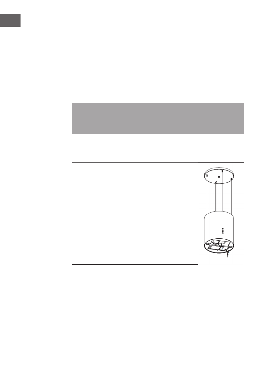
62
FR
Inox
L’inox doit être nettoyé régulièrement (chaque semaine) pour garantir sa
longévité. Pour cela, utiliser un détergent liquide spécial inox.
Panneau de commande
Le panneau de commande peut être nettoyé avec de l’eau savonneuse chaude.
S’assurer que le chiffon soit propre et bien essoré avant de nettoyer le panneau de
commande. Utiliser un chiffon doux et sec pour retirer l’humidité superue après
le nettoyage.
Important : Utiliser un détergent neutre et éviter d’utiliser des détergents
fortement chimiques, de forts produits ménagers ou des produits contenant
des substances abrasives car cela endommage l’apparence de l’appareil et peut
éventuellement effacer les symboles imprimés sur le panneau de commande.
Filtre à graisse
Les ltres en tissu peuvent être lavés à la main. Les laisser
tremper env. 3 mn dans de l’eau avec un détergent
anti-graisses puis les brosser délicatement avec une
brosse douce. Ne pas exercer trop de pression pour ne
pas endommager le ltre. Laisser ensuite le ltre sécher
à l’air libre, mais pas directement au soleil. Les ltres
doivent toujours être lavés séparément de la vaisselle et
des ustensiles de cuisine !
Retirer le ltre comme sur l’illustration à droite
puis le replacer dans l’ordre inverse.

63
FR
Filtre au charbon actif
Il est possible d’utiliser des ltres au charbon actif pour éliminer les odeurs.
Normalement, le ltre au charbon actif doit être remplacer tous les trois ou six
mois, selon les habitudes de cuisine. Installer le ltre au charbon actif comme suit :
1 Débrancher la hotte d’aspiration de la prise électrique.
2 Appuyer sur la fermeture du ltre et retirer le ltre d’alimentation.
3 Tourner le ltre au charbon actif dans le sens contraire aux aiguilles d’une
montre des chaque côté du moteur. Remplacer les vieux ltres au charbon
actif par de nouveaux ltres.
4 Replacer le ltre d’alimentation.
5 Rebrancher la hotte d’aspiration.
Remarque : S’assurer que le ltre est bien refermé. Sinon, il peut se détacher,
ce qui est dangereux. Si un ltre au charbon actif est installé, la puissance
d’aspiration est diminuée.
ouvrir
fermer
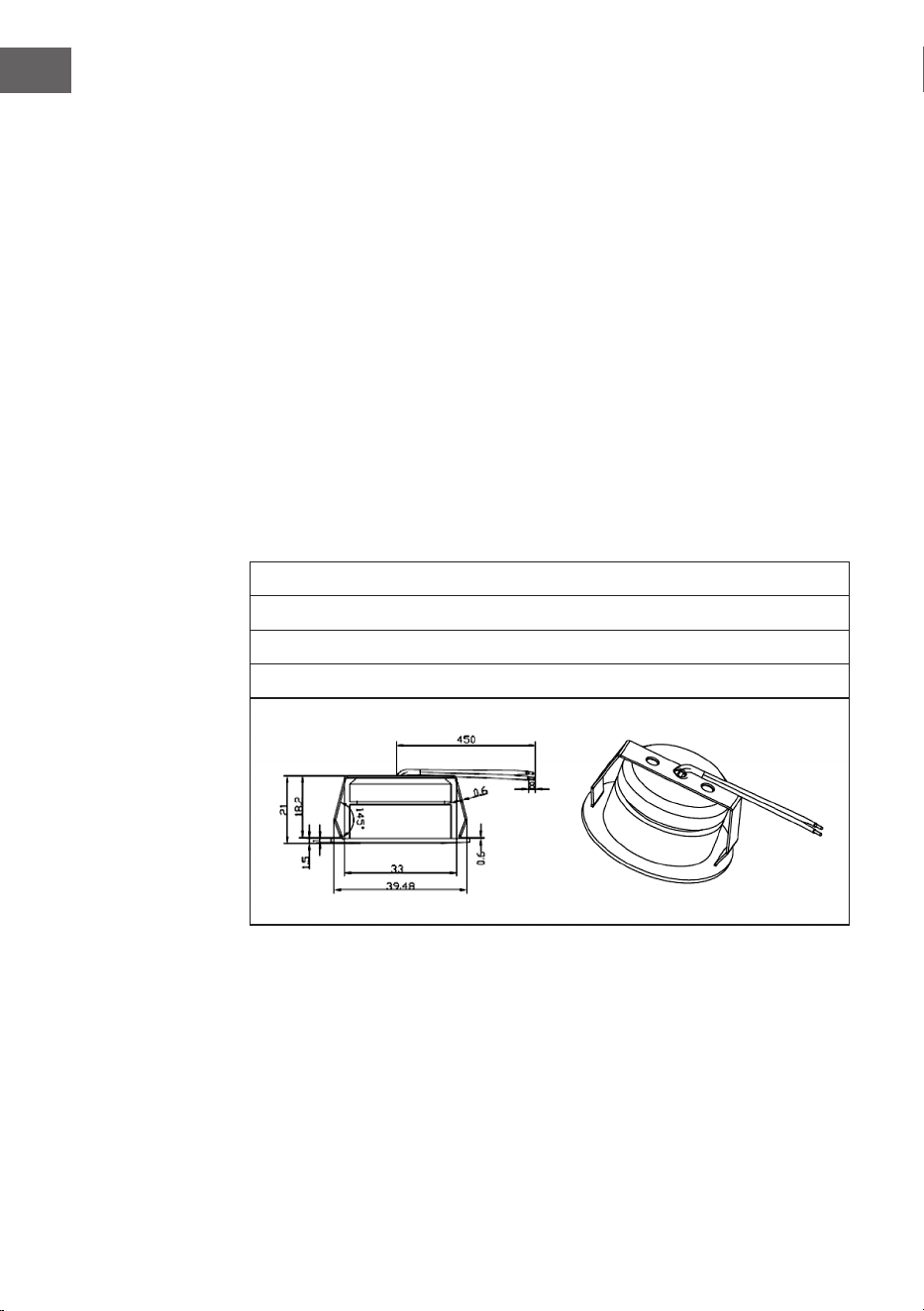
64
FR
Changer la lampe
• L’a lampe doit être changée par le fabricant, son service client ou une
personne également qualiée.
• Couper toujours l’arrivée électrique avant d’entreprendre n’importe quel
travail sur l’appareil. Lors de travaux avec l’ampoule, veiller à ce qu’elle soit
bien refroidie avant de la toucher directement à mains nues.
• Toujours maintenir fermement l’ampoule avec un chiffon ou des gants pour
l’installer ou la retirer, s’assurer que l’ampoule n’entre pas en contact avec de
la sueur car cela peut réduire sa longévité.
Pour changer la lampe :
1 Avant de changer l’éclairage, s’assurer que la hotte d’aspiration est éteinte.
2 Tourner le couvercle dans le sens contraire aux aiguilles d’une montre.
Dévisser les vis du lltre en inox et le retirer.
3 Appuyer sur le raccordement de la lampe pour la retirer.
4 Installer la nouvelle lampe et rebrancher l’appareil.
Informations importantes concernant l’ampoule
Type de LED : lampe en verre ronde
Wattage maximal : 2 x 1 W
Gamme de tension :12 V
Dimensions : voir illustration

65
FR
INFORMATIONS SUR LA PROTECTION DE
L‘ENVIRONNEMENT
• Assurez-vous qu‘il y a une ventilation susante pendant la cuisson pour que
la hotte aspirante puisse fonctionner ecacement et avec un faible niveau
sonore.
• Ajustez la vitesse du ventilateur à la quantité de vapeur produite pendant la
cuisson. Utilisez le mode intensif uniquement lorsque cela est nécessaire.
Plus la vitesse du ventilateur est basse, moins la consommation d‘énergie est
réduite.
• Si de grandes quantités de vapeur sont produites pendant la cuisson,
sélectionnez une vitesse de ventilation plus élevée en temps utile. Si la
vapeur de cuisson est déjà répartie dans la cuisine, la hotte aspirante devra
fonctionner plus longtemps.
• Éteignez la hotte aspirante lorsque vous n‘en avez plus besoin.
• Éteignez l‘éclairage lorsque vous n‘en avez plus besoin.
• Nettoyez le ltre à intervalles réguliers et remplacez-le si nécessaire an
d‘augmenter l‘ecacité du système de ventilation et d‘éviter les risques
d‘incendie.
• Mettez toujours le couvercle pendant la cuisson pour réduire la vapeur et la
condensation.

66
FR
FICHE DE DONNÉES PRODUIT
Informations selon le règlement (UE) n ° 65/2014
Méthodes de mesure et de calcul selon EN 61591:1997+A1:2006+A2:2011+A11:201
4+A12:2015
Numéro d‘article 10037863, 10037864, 10037865
Description Symbole Valeur Unité
Consommation annuelle d'énergie AEC
hood
16,3 kWh/Année
Classe d'ecacité énergétique A+
Ecacité dynamique des uides FDE
hood
26,6
Classe d'ecacité dynamique des uides B
Ecacité lumineuse LE
hood
95,4 Lux/W
Classe d'ecacité lumineuse A
Ecacité de séparation des graisses GFE
hood
83,7 %
Clase d'ecacité de capture des graisses C
Débit d'air à vitesse minimale et maximale
en fonctionnement normal, à l'exception
du fonctionnement au niveau intensif ou au
niveau haute vitesse
188 / 518 m³/h
Flux d'air pendant le fonctionnement au
niveau intensif ou au niveau haute vitesse
- m³/h
Niveau sonore de classe A aux vitesses
minimale et maximale disponibles en
fonctionnement normal
42 / 65 dB
Niveau sonore de classe A en
fonctionnement au niveau intensif ou au
niveau haute vitesse
- dB
Consommation d'énergie appareil éteint P
o
- W
Consommation électrique en veille P
s
0,48 W
Coordonnées de contact Chal-Tec GmbH, Wallstraße 16,
10179, Berlin, Allemagne
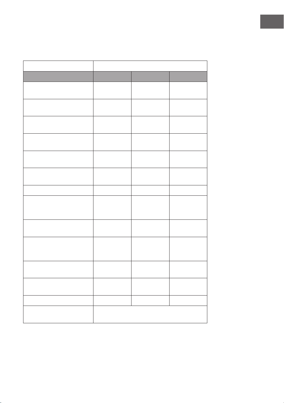
67
FR
Informations selon le règlement (UE) n ° 66/2014
Méthodes de mesure et de calcul selon EN 61591:1997+A1:2006+A2:2011+A11:201
4+A12:2015
Numéro d‘article 10037863, 10037864, 10037865
Description Symbole Valeur Unité
Consommation annuelle
d'énergie
AEC
hood
16,3 kWh/Année
Facteur d'extension de
temps
f 1,0
Ecacité dynamique des
uides
FDE
hood
26,6
Indice d'ecacité
énergétique
EEI
hood
43,1
Débit d'air mesuré au
meilleur point
Q
BEP
174,9 m³/h
Pression d'air mesurée au
meilleur point
P
BEP
204 Pa
Débit d'air maximal Q
max
518 m³/h
Puissance électrique
d'entrée mesurée au
meilleur point
W
BEP
37,3 W
Puissance nominale du
système d'éclairage
W
L
3,7 W
Puissance moyenne du
système d'éclairage sur la
surface de cuisson
E
middle
352,8 Lux
Consommation d‘énergie
mesurée appareil éteint
P
o
- W
Consommation électrique
mesurée en mode veille
P
s
0,48 W
Niveau sonore L
WA
42 / 65 dB
Coordonnées de contact Chal-Tec GmbH, Wallstraße 16,
10179, Berlin, Allemagne

68
FR
INFORMATIONS SUR LE RECYCLAGE
S‘il existe une réglementation pour l‘élimination ou le
recyclage des appareils électriques et électroniques dans
votre pays, ce symbole sur le produit ou sur l‘emballage
indique que cet appareil ne doit pas être jeté avec les
ordures ménagères. Vous devez le déposer dans un point
de collecte pour le recyclage des équipements électriques
et électroniques. La mise au rebut conforme aux règles
protège l‘environnement et la santé de vos semblables
des conséquences négatives. Pour plus d‘informations
sur le recyclage et l‘élimination de ce produit, veuillez
contacter votre autorité locale ou votre service de
recyclage des déchets ménagers.
FABRICANT ET IMPORTATEUR (UK)
Fabricant :
Chal-Tec GmbH, Wallstraße 16, 10179 Berlin, Allemagne.
Importateur pour la Grande Bretagne :
Berlin Brands Group UK Limited
PO Box 42
272 Kensington High Street
London, W8 6ND
United Kingdom
69
IT
Gentile cliente,
La ringraziamo per aver acquistato il dispositivo. La
preghiamo di leggere attentamente le seguenti istruzioni
per l’uso e di seguirle per evitare possibili danni. Non ci
assumiamo alcuna responsabilità per danni scaturiti da una
mancata osservazione delle avvertenze di sicurezza e da
un uso improprio del dispositivo. Scansionare il codice QR
seguente, per accedere al manuale d’uso più attuale e per
ricevere informazioni sul prodotto.
INDICE
Avvertenze di sicurezza 70
Installazione (ventilazione esterna) 72
Indicazioni sul montaggio del tubo di scarico 74
Pannello di controllo 75
Utilizzo 75
Ricerca e risoluzione dei problemi 77
Pulizia e manutenzione 77
Indicazioni per la tutela dell’ambiente 81
Scheda dati del prodotto 82
Avviso di smaltimento 84
Produttore e importatore (UK) 84
DATI TECNICI
Articolo numero 10037863, 10037864, 10037865
Alimentazione 220-240 V ~ 50 Hz

70
IT
AVVERTENZE DI SICUREZZA
• Leggere attentamente tutte le istruzioni prima dell´uso e conservare il ma-
nuale per consultazioni future.
• Il montaggio può essere eseguito solo da un tecnico qualicato. Prima di
utilizzare la cappa aspirante, accertarsi che la tensione (V) e la frequenza (Hz)
indicate corrispondano alla tensione (V) e alla frequenza (Hz) domestiche.
• Si declina ogni responsabilità per danni derivati da un utilizzo improprio e da
un´installazione errata della cappa aspirante.
• I bambini minori di 8 anni non possono utilizzare la cappa aspirante.
• La cappa aspirante non è per un uso commerciale bensì domestico e in am-
bienti simili.
• Pulire regolarmente la cappa aspirante e il ltro per un corretto funzionamen-
to.
• Staccare la spina dalla presa prima di eseguire la pulizia.
• Pulire la cappa aspirante come indicato nel manuale di istruzioni. Non utilizza-
re amme vive sotto la cappa aspirante.
• Se la cappa aspirante non funziona correttamente, rivolgersi al produttore o
ad un tecnico competente.
• Questo dispositivo può essere utilizzato da bambini a partire da 8 anni e da
persone con limitate capacità siche e psichiche o con conoscenza ed espe-
rienza limitate, solo se sono stati istruiti sulle modalità d’uso e comprendono i
rischi e i pericoli connessi.
• Se il cavo di alimentazione o la spina sono danneggiati, farli sostituire dal
produttore o da un tecnico qualicato.
• Se la cappa aspirante viene utilizzata insieme ad apparecchi che bruciano gas
o combustibili, è necessario che la stanza sia ben ventilata.
• Non cucinare alimenti alla amma (ambé) sotto la cappa aspirante.
• Attenzione: le superci della cappa aspirante possono diventare molto calde
durante l´uso.
Note importanti per l´installazione
• L´aria non deve essere condotta in uno scarico utilizzato per aspirare gas di
combustione o altri combustibili (ciò non si applica per dispositivi che emetto-
no solo aria nella stanza).
• Osservare tutte le disposizioni regionali relative all´incasso di dispositivi di
ventilazione.

71
IT
Note importanti circa la modalità di estrazione
AVVERTENZA
Pericolo di morte, pericolo di intossicazione da gas di scarico! Non
azionare l´apparecchio con funzione di scarico mentre è attivo un
impianto di riscaldamento che utilizza l´aria ambiente, se
l´areazione non è suciente.
Gli impianti di riscaldamento che sfruttano l´aria ambiente (ad es. stufe a gas, ad
gasolio, a legna o a carbone, scalda-acqua istantanei, scaldabagno), usano l´aria
ambiente per la combustione ed espellono all´esterno i gas di scarico attraverso
un sistema di scarico (ad es. camino). Con la cappa aspirante accesa viene
sottratta aria dalla cucina e dalle stanze adiacenti. Se l´areazione è insuciente si
forma una depressione. I gas tossici del camino vengono riaspirati negli ambienti
domestici.
• Pertanto è necessario che ci sia sempre un´areazione suciente.
• La cassetta a muro per areazione o sato da sola non garantisce un´areazione
suciente.
Un utilizzo sicuro è possibile solo se la depressione nella stanza dove è installato
l´impianto di riscaldamento non supera i 4 Pa (0,04 mbar). Ciò è possibile solo
se l´aria necessaria per la combustione può auire nella stanza attraverso
aperture permanenti come porte, nestre, in combinazione con una cassetta a
muro per areazione o sato o con altre misure tecniche. In ogni caso rivolgersi
ad un esperto di impianti di areazione il quale fornirà indicazioni sulle misure da
intraprendere per una corretta areazione.
Se la cappa aspirante viene impiegata esclusivamente con funzione di ricircolo
dell´aria, l´utilizzo è possibile senza limiti.
Informazioni importanti per smontare il dispositivo
• Lo smontaggio avviene seguendo i passaggi relativi a installazione/montaggio
in ordine inverso.
• Chiedere l’aiuto di una seconda persona per smontare il dispositivo, in modo
da evitare lesioni.
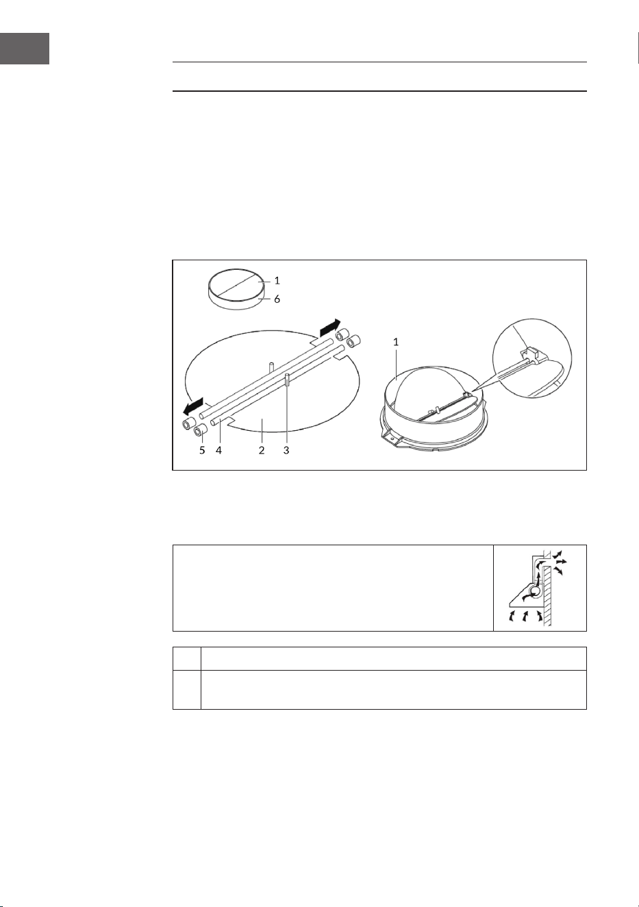
72
IT
INSTALLAZIONE (VENTILAZIONE ESTERNA)
Montaggio della valvola a farfalla antiritorno
Se la cappa aspirante non è dotata della valvola a farfalla antiritorno
preassemblata, installare i pezzi nel modo seguente:
1. Montare la prima metà (2) nell'alloggiamento (6).
2. Il perno (3) deve puntare verso l'alto.
3. Inserire l'asse (4) nei fori (5) presenti nell'alloggiamento.
4. Ripetere tutti i passaggi per la seconda metà della valvola a farfalla
antiritorno.
Installazione
Se si ha uno scarico dell'aria verso l'esterno, si può
collegare la cappa aspirante a un canale di scarico
(smaltato, d'alluminio, tubo essibile oppure di
materiale ignifugo con un diametro interno di 150
mm) come ragurato a destra.
1 Staccare la spina dalla presa prima dell'installazione.
2
La cappa aspirante deve essere montata a una distanza di 65-
75 cm sopra il piano cottura per ottenere il massimo effetto.

73
IT
3
Praticare 3 fori (Ø 8 mm) in un punto adatto della parete dopo
aver stabilito a quale altezza si desidera installare la cappa.
4
Inserire i tasselli nei fori, non avvitare completamente le 2 viti ST4*30
mm nei tasselli per ssare il corpo della cappa (vedi gura).
5
Montare la valvola a farfalla antiritorno e il tubo di espansione sulla
cappa aspirante. Fissare il tubo con delle fascette per cavo (vedi gura A).
Appendere la cappa aspirante alle viti e ssare l'alloggiamento con 1 vite
di sicurezza ST4*30 mm. Nota: entrambe le prese di ventilazione (diametro
di 6 mm) si trovano nell'alloggiamento posteriore (vedi gura B).
A B
6
Condurre il tubo di espansione verso l'esterno.
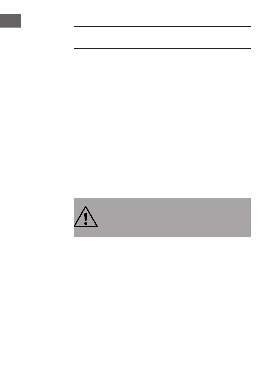
74
IT
INDICAZIONI SUL MONTAGGIO DEL TUBO DI
SCARICO
Rispettare assolutamente le seguenti regole per ottenere una perfetta aspirazione
d'aria:
• Assicurarsi che il tubo di scarico sia dritto e non molto lungo.
• Non ridurre le dimensioni del tubo e non comprimerlo.
I tubi di scarico devono essere sempre diritti per ridurre la perdita di
pressione.
• L'inosservanza di queste disposizioni fondamentali abbassa il rendimento e
alza le emissioni sonore della cappa aspirante.
• Il montaggio può essere eseguito solo da un tecnico qualicato.
• Non collegare il tubo di scarico della cappa a un sistema di ventilazione già
presente che viene utilizzato per un altro dispositivo, p. es. canna fumaria, tubi
del gas oppure tubi per la canalizzazione d'aria calda.
• Se il tubo di scarico deve fare una curva, l'angolo non deve essere minore di
120°. Non indirizzare il tubo verso il basso, ma posarlo sempre in orizzontale
oppure farlo passare dal punto iniziale verso la presa d'aria in alto sulla parete
esterna.
• Assicurarsi dopo il montaggio che la cappa aspirante sia appesa
orizzontalmente per evitare che il grasso si accumuli.
• Assicurarsi che il tubo di scarico scelto per l'installazione sia ignifugo e
conforme alle norme.
ATTENZIONE
Pericolo di lesioni! Per motivi di sicurezza, utilizzare esclusivamente
viti di ssaggio o di montaggio di dimensioni consigliate nel manuale
d'uso. L'inosservanza delle istruzioni può causare lesioni e
folgorazioni.

75
IT
PANNELLO DI CONTROLLO
Tasto BASSO (velocità ventola bassa)
Tasto MEDIO (velocità ventola media)
Tasto ALTO (velocità ventola alta)
Tasto LUCE (luce on/off)
Tasto POWER (cappa aspirante on/off)
UTILIZZO
1. Quando si inserisce la spina nella presa, si accendono tutte le luci. Il
dispositivo entra in modalità standby. Se non si preme alcun tasto, la spia si
spegne automaticamente.
2. Accensione: quando si preme il tasto POWER, la spia si accende e la cappa
aspirante si aziona a velocità bassa. La spia del tasto BASSO è acceso. Se
si preme nuovamente POWER il dispositivo si spegne. Tutte le funzioni si
interrompono e il dispositivo entra in modalità standby. I tasti velocità e
LUCE possono essere usati indipendentemente dal tasto POWER. Quando si
preme un determinato tasto funzione, la cappa aspirante entra nella modalità
corrispondente. Quando si preme il POWER in qualsiasi modalità, il dispositivo
si spegne e tutte le funzioni si interrompono.
3. Se si preme una volta LUCE, si accende la luce. Le spie LUCE e POWER si
accendono. Premere di nuovo LUCE per spegnere la luce. Le spie LUCE e
POWER si spengono.

76
IT
4. Se si preme una volta il tasto ALTO, il motore gira a velocità elevata e le spie
LUCE e POWER si accendono. Se si preme ancora il tasto ALTO, il motore si
ferma. Le spie ALTO e POWER si spengono.
5. Se si preme una volta il tasto MEDIO, il motore gira a velocità media e le spie
MEDIO e POWER si accendono. Se si preme ancora il tasto MEDIO, il motore si
ferma. Le spie MEDIO e POWER si spengono.
6. Se si preme una volta il tasto BASSO, il motore gira a velocità bassa e le spie
BASSO e POWER si accendono. Se si preme ancora il tasto BASSO, il motore si
ferma. Le spie BASSO e POWER si spengono.
7. E' possibile impostare soltanto una velocità. Non si possono impostare due
velocità contemporaneamente. Se la cappa aspirante funziona a velocità
elevata e si preme il tasto BASSO, la cappa funzionerà a velocità bassa. Se la
cappa aspirante funziona a velocità bassa e si preme il tasto MEDIO, la cappa
funzionerà a velocità media e così via.
77
IT
RICERCA E RISOLUZIONE DEI PROBLEMI
Problema Causa Soluzione
La luce è accesa,
ma il motore non si
mette in funzione.
Il motore è spento. Accendere il motore
con il tasto SPEED.
L´interruttore del
motore è danneggiato.
Contattare un tecnico.
Il motore è danneggiato. Contattare un tecnico.
La luce e il motore
non funzionano.
Un fusibile è guasto. Sostituire il fusibile.
Il cavo di alimentazione
è allentato oppure
non collegato.
Collegare correttamente
il cavo di alimentazione.
La luce non funziona. La lampadina è rotta. Sostituire la lampadina.
La potenza aspirante
è ridotta.
Troppa distanza tra
la cappa e i fornelli.
Ridurre la distanza.
La cappa non è appesa
correttamente.
Una delle viti di
ssaggio non è
serrata saldamente.
Serrare la vite
saldamente.
PULIZIA E MANUTENZIONE
Prima di effettuare qualsiasi operazione di manutenzione o di pulizia, staccare
sempre la cappa aspirante dall´alimentazione. Accertarsi inoltre che la cappa
aspirante sia spenta e che la spina sia stata disinserita. Le superci esterne sono
soggette a gra e ammaccature, pertanto seguire le istruzioni per pulire la cappa
senza danneggiarla.
Avvertenze generali
Lasciare raffreddare completamente la cappa aspirante prima di pulirla e non
utilizzare sostanze alcaline o acide come succo di limone o aceto.
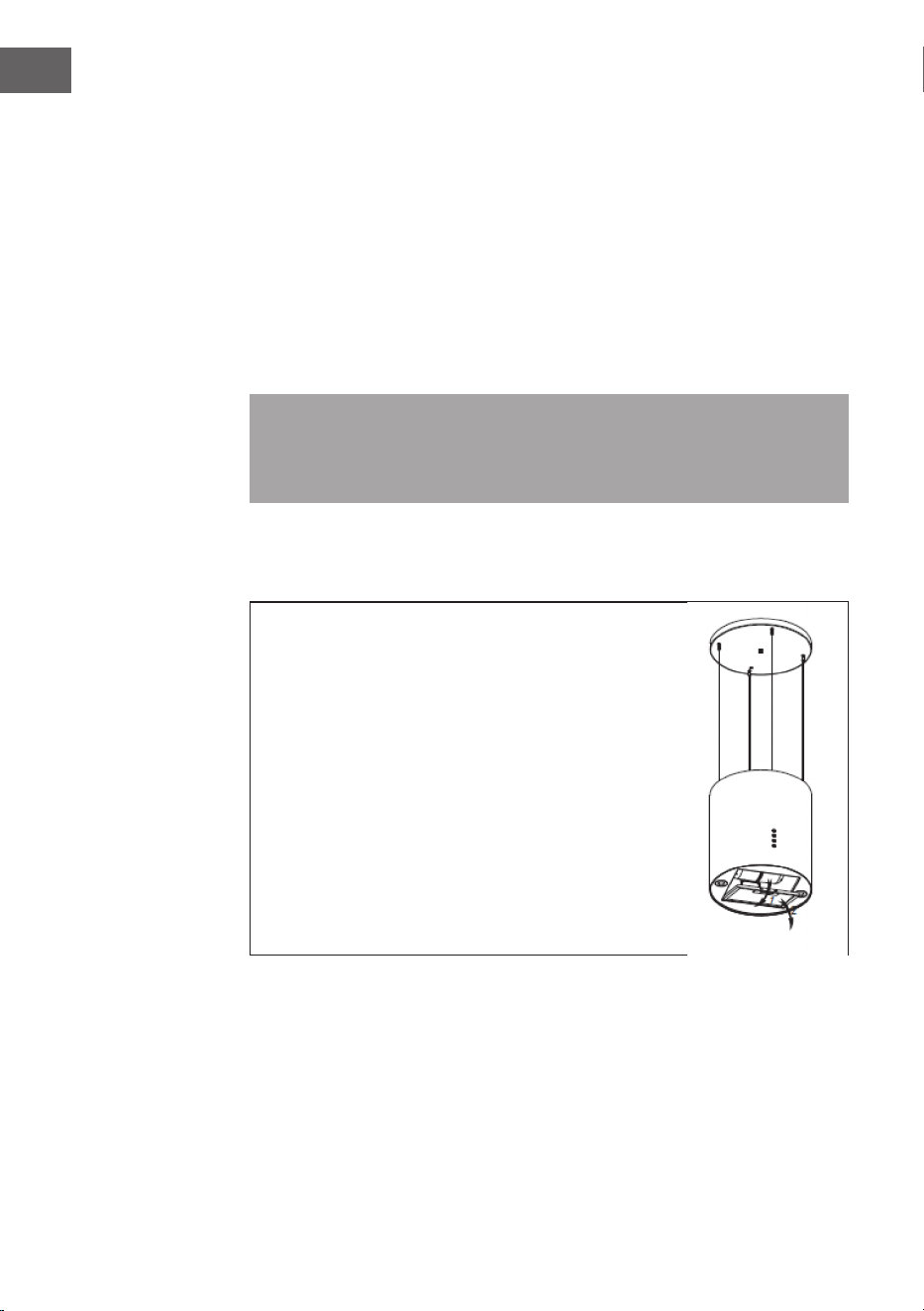
78
IT
Acciaio inossidabile
L‘acciaio inossidabile deve essere pulito regolarmente (settimanalmente) per
garantirne una lunga durata. A tale scopo si può utilizzare un detergente specico
per acciaio inossidabile.
Pannello dei comandi
Il pannello dei comandi può essere pulito con acqua tiepida e sapone. Assicurarsi
che il panno sia pulito e ben strizzato prima di pulire il pannello dei comandi.
Usare un panno asciutto e morbido per rimuovere l‘umidità in eccesso dopo la
pulizia.
Importante: utilizzare detergenti neutri ed evitare l‘uso di detergenti aggressivi,
o di prodotti contenenti agenti abrasivi, in quanto ciò potrebbe danneggiare le
superci dell´apparecchio e potrebbe rimuovere i simboli stampati sul pannello
dei comandi.
Filtro antigrasso
I ltri in tessuto possono essere lavati manualmente.
Immergerli in acqua per circa 3 minuti con un detergente
sgrassante e spazzolarli delicatamente con una spazzola
morbida. Non esercitare troppa pressione per evitare di
danneggiare il ltro. Lasciare asciugare il ltro all‘aria,
senza esporlo alla luce diretta del sole. Non lavare i ltri
insieme a piatti e a utensili da cucina!
Rimuovere il ltro come mostrato nella gura a
destra e reinserirlo in ordine inverso.

79
IT
Filtro a carboni attivi
I ltri a carboni attivi sono utilizzati per eliminare gli odori. Normalmente il ltro
a carboni attivi deve essere sostituito dopo tre o sei mesi in base alla frequenza
di utilizzo della cappa aspirante. L‘installazione del ltro a carboni attivi si esegue
come segue:
1 Prima dell‘installazione, disinserire la spina dalla presa.
2 Premere il cappuccio e rimuovere il ltro a rete.
3 Ruotare il ltro a carboni attivi su entrambi i lati del motore in senso
antiorario. Sostituire i vecchi ltri a carbone con ltri nuovi.
4 Inserire di nuovo il ltro a rete.
5 Inserire di nuovo la spina nella presa di corrente.
Nota: assicurarsi che il ltro sia ben chiuso. In caso contrario può allentarsi e
diventare pericoloso. Quando il ltro a carboni attivi è collegato, la potenza di
aspirazione si riduce.
öffnen
schließen
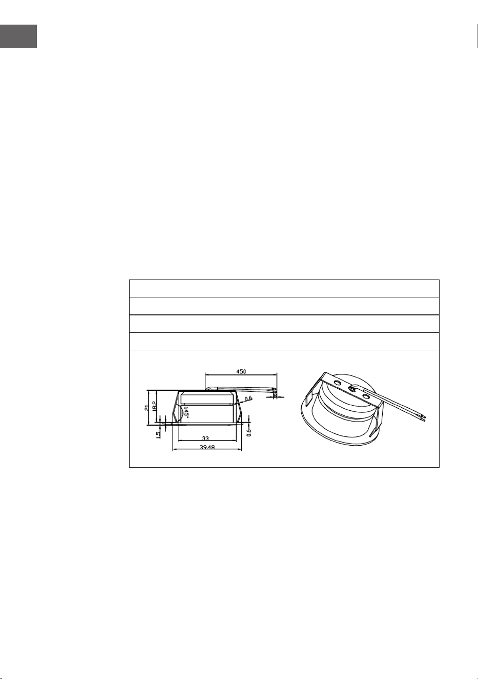
80
IT
Sostituzione della lampadina
• La lampadina deve essere sostituita dal produttore, dal suo servizio clienti o
da personale qualicato.
• Prima di effettuare qualsiasi intervento sull‘apparecchio, disinserire sempre
la spina dalla presa. Quando si maneggia la lampadina, assicurarsi che si sia
completamente raffreddata prima di toccarla con le mani.
• Rimuovere o inserire la lampadina afferrandola con un panno o con dei
guanti.
Sostituire la lampadina:
1 Prima di cambiare la lampadina, assicurarsi che la cappa aspirante sia spenta.
2 Ruotare il coperchio in senso antiorario. Allentare la vite del ltro in acciaio
inox e rimuoverla.
3 Premere il connettore della lampadina per rimuoverla.
4 Installare la nuova lampadina e ricollegare il cavo.
Informazioni importanti sulla lampadina
Tipo di LED: Lampada rotonda in vetro
Potenza massima: 2 x 1 W
Gamma di tensione:12 V
Dimensioni: vedere la gura

81
IT
INDICAZIONI PER LA TUTELA DELL’AMBIENTE
• Mentre si cucina, assicurare un suciente usso d’aria, in modo che la
cappa aspirante possa funzionare in modo eciente e con bassa rumorosità
operativa.
• Regolare la velocità della ventola in base alla quantità di vapore generato
durante la cottura. Utilizzare la modalità di funzionamento intenso solo se
necessario. Minore la velocità della ventola, minori i consumi energetici.
• Se durante la preparazione di grandi quantità di alimenti si forma molto
vapore, selezionare per tempo una velocità maggiore della ventola. Se il
vapore si è già diffuso nella cucina, sarà necessario lasciare in funzione più a
lungo la cappa aspirante.
• Spegnere la cappa quando non è più necessaria.
• Spegnere la luce quando non è più necessaria.
• Pulire il ltro a intervalli regolari e sostituirlo secondo necessità, in modo da
incrementare l’ecacia del sistema di ventilazione e da evitare il rischio di
incendi.
• Mettere sempre il coperchio sulle pentole quando si cucina, per ridurre vapore
e condensa.
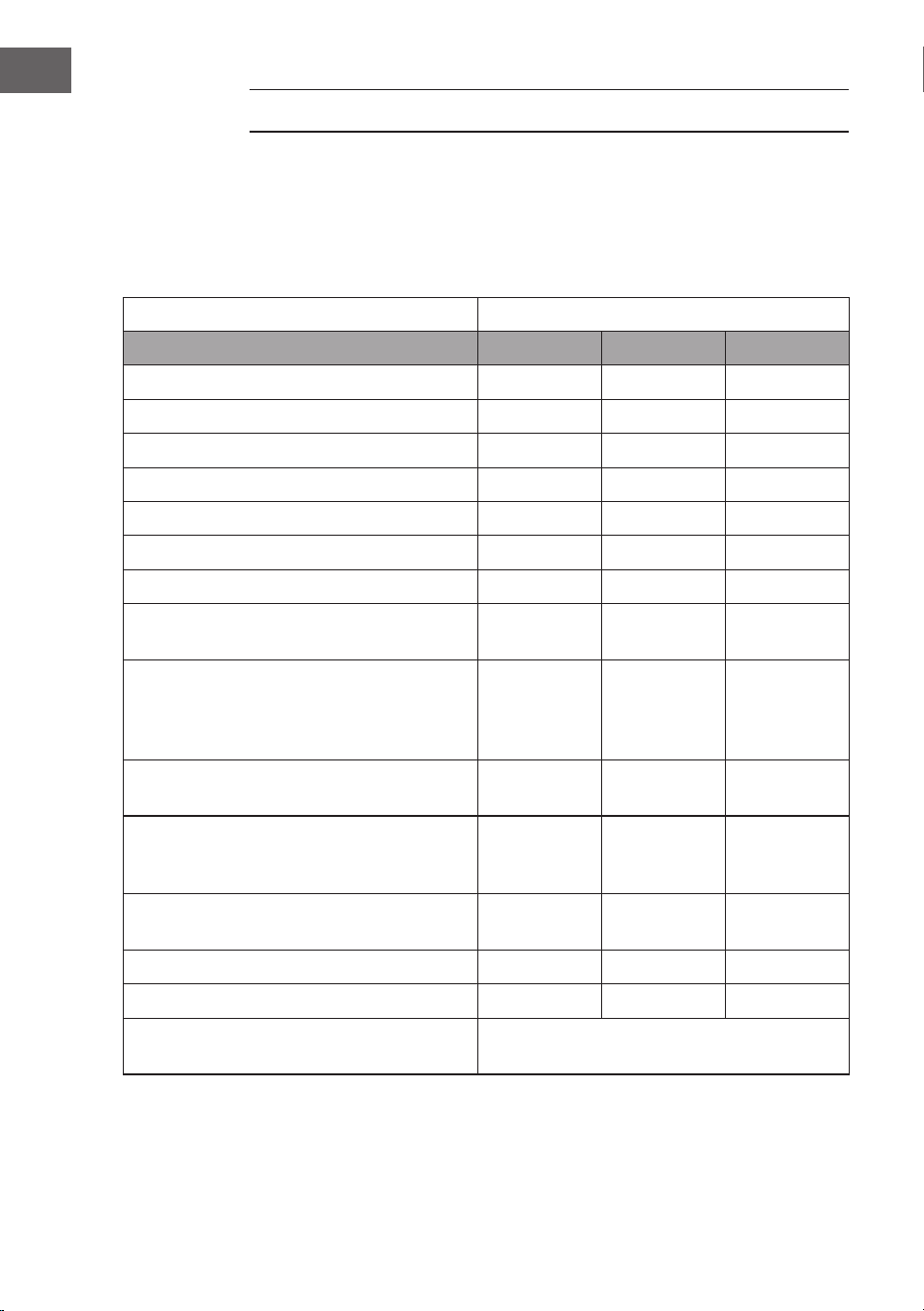
82
IT
SCHEDA DATI DEL PRODOTTO
Indicazioni conformi alla direttiva (UE) N° 65/2014
Metodi di misurazione e calcolo conformi a EN 61591:1997+A1:2006+A2:2011+A11:
2014+A12:2015
Numero articolo 10037863, 10037864, 10037865
Denizione Simbolo Valore Unità
Consumo energetico annuale AEC
hood
16,3 kWh/anno
Classe di ecienza energetica A+
Ecienza uidodinamica FDE
hood
26,6
Classe di ecienza uidodinamica B
Ecienza luminosa LE
hood
95,4 Lux/W
Classe di ecienza luminosa A
Grado di separazione del grasso GFE
hood
83,7 %
Classe relativa al grado di separazione del
grasso
C
Flusso d’aria a velocità minima in
funzionamento normale, escluso il
funzionamento a livello intenso o ad alta
velocità.
188 / 518 m³/h
Flusso d’aria in funzionamento intenso o ad
alta velocità.
- m³/h
Livello di emissioni sonore ponderato A, nelle
velocità massima e minima disponibili in
funzionamento normale.
42 / 65 dB
Livello di emissioni sonore ponderato A, in
funzionamento intenso o ad alta velocità.
- dB
Potenza assorbita a dispositivo spento P
o
- W
Potenza assorbita a dispositivo in standby P
s
0,48 W
Informazioni di contatto Chal-Tec GmbH, Wallstraße 16,
10179, Berlino, Germania
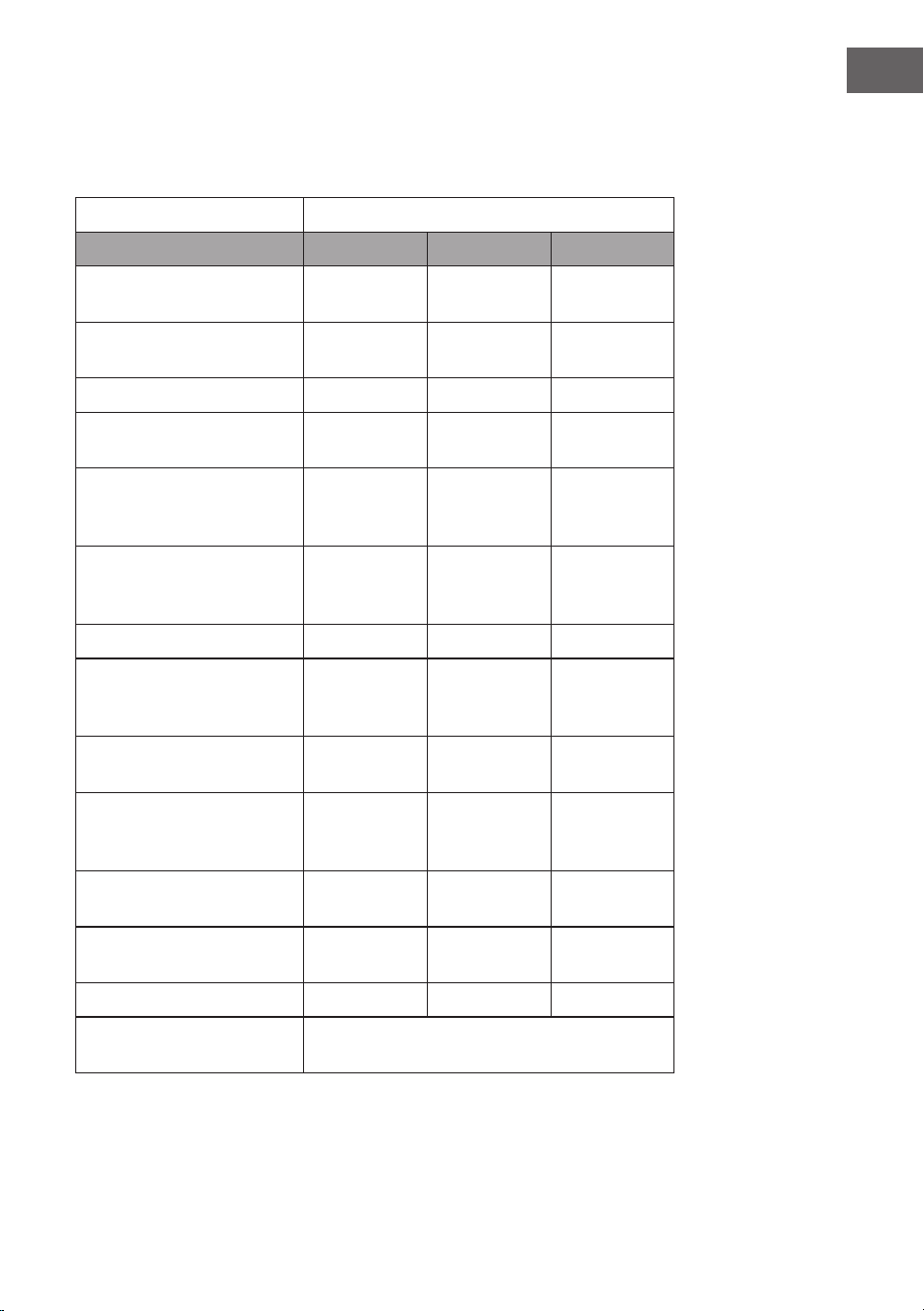
83
IT
Indicazioni conformi alla direttiva (UE) N° 66/2014
Metodi di misurazione e calcolo conformi a EN 61591:1997+A1:2006+A2:2011+A11:
2014+A12:2015
Numero articolo 10037863, 10037864, 10037865
Denizione Simbolo Valore Unità
Consumo energetico
annuale
AEC
hood
16,3 kWh/anno
Fattore di incremento nel
tempo
f 1,0
Ecienza uidodinamica FDE
hood
26,6
Indice di ecienza
energetica
EEI
hood
43,1
Volume del usso d’aria
misurato nel punto di
massima ecienza
Q
BEP
174,9 m³/h
Pressione dell’aria misurata
nel punto di massima
ecienza
P
BEP
204 Pa
Flusso d’aria massimo Q
max
518 m³/h
Potenza elettrica in entrata
misurata nel punto di
massima ecienza
W
BEP
37,3 W
Potenza nominale del
sistema di illuminazione
W
L
3,7 W
Intensità luminosa media del
sistema di illuminazione sul
piano cottura
E
middle
352,8 Lux
Potenza assorbita misurata a
dispositivo spento
P
o
- W
Potenza assorbita misurata a
dispositivo in standby
P
s
0,48 W
Livello di rumorosità L
WA
42 / 65 dB
Informazioni di contatto Chal-Tec GmbH, Wallstraße 16,
10179, Berlino, Germania

84
IT
AVVISO DI SMALTIMENTO
Se nel proprio paese si applicano le regolamentazioni
inerenti lo smaltimento di dispositivi elettrici ed
elettronici, questo simbolo sul prodotto o sulla confezione
segnala che questi prodotti non possono essere
smaltiti con i riuti normali e devono essere portati a
un punto di raccolta di dispositivi elettrici ed elettronici.
Grazie al corretto smaltimento dei vecchi dispositivi si
tutela il pianeta e la salute delle persone da possibili
conseguenze negative. Informazioni riguardanti il riciclo
e lo smaltimento di questi prodotti si ottengono presso
l’amministrazione locale oppure il servizio di gestione dei
riuti domestici.
PRODUTTORE E IMPORTATORE (UK)
Produttore:
Chal-Tec GmbH, Wallstraße 16, 10179 Berlino, Germania.
Importatore per la Gran Bretagna:
Berlin Brands Group UK Limited
PO Box 42
272 Kensington High Street
London, W8 6ND
United Kingdom