Original instructions
Industrial Robot: SCARA ROBOT
T-B series
MANUAL
Rev.6 ENM238R5896F

SCARA Robots
T-B series Manual Rev.6

T-B series Rev.6 i
Industrial Robot: SCARA ROBOT
T-B series Manual
Rev.6
Seiko Epson Corporation 2021-2023

ii T-B series Rev.6
FOREWORD
Thank you for purchasing our robot products.
This manual contains the information necessary for the correct use of the manipulator and
the integrated Controller.
Please carefully read this manual and other related manuals before installing the robot
system.
Keep this manual handy for easy access at all times.
The robot system and its optional parts are shipped to our customers only after being
subjected to the strictest quality controls, tests, and inspections to certify its compliance with
our high performance standards. Please note that the basic performance of the product will
not be exhibited if our robot system is used outside of the usage conditions and product
specifications described in the manuals.
This manual describes possible dangers and consequences that we can foresee. Be sure to
comply with safety precautions on this manual to use our robot system safety and correctly.
TRADEMARKS
Microsoft, Windows, and Windows logo are either registered trademarks or trademarks of
Microsoft Corporation in the United States and/or other countries. Other brand and
product names are trademarks or registered trademarks of the respective holders.
TRADEMARK NOTATION IN THIS MANUAL
Microsoft® Windows® 8 operating system
Microsoft® Windows® 10 operating system
Microsoft® Windows® 11 operating system
Throughout this manual, Windows 8, Windows 10 and Windows 11 refer to above respective
operating systems. In some cases, Windows refers generically to Windows 8, Windows 10
and Windows 11.
NOTICE
No part of this manual may be copied or reproduced without authorization.
The contents of this manual are subject to change without notice.
Please notify us if you should find any errors in this manual or if you have any comments
regarding its contents.
MANUFACTURER
CONTACT INFORMATION
Contact information is described in “SUPPLIERS” in the first pages of the following
manual:
Robot System Safety Manual Read this manual first
T-B series Rev.6 iii
DISPOSAL
When disposing this product, dispose in accordance with the laws and regulations of each
country.
Regarding battery disposal
The battery removal/replacement procedure is described in the following manuals:
Maintenance Manual
For European Union customers only
The crossed out wheeled bin label that can be found on your product indicates that this
product and incorporated batteries should not be disposed of via the normal household waste
stream. To prevent possible harm to the environment or human health please separate this
product and its batteries from other waste streams to ensure that it can be recycled in an
environmentally sound manner. For more details on available collection facilities please
contact your local government office or the retailer where you purchased this product. Use
of the chemical symbols Pb, Cd or Hg indicates if these metals are used in the battery.
This information only applies to customers in the European Union, according to Directive
2006/66/EC OF THE EUROPEAN PARLIAMENT AND OF THE COUNCIL OF 6
September 2006 on batteries and accumulators and waste batteries and accumulators and
repealing Directive 91/157/EEC and legislation transposing and implementing it into the
various national legal systems, and to customers in countries in Europe, Middle East and
Africa (EMEA) where they have implemented equivalent regulations.
For other countries, please contact your local government to investigate the possibility of
recycling your product.
For Users in Taiwan region
Please separate used batteries from other waste streams to ensure that it can be recycled in
an environmentally sound manner. For more details on available collection facilities please
contact your local government office or the retailer where you purchased this product.
For California customers only
The lithium batteries in this product contain
Perchlorate Material - special handling may apply,
See www.dtsc.ca.gov/hazardouswaste/perchlorate
NOTE
iv T-B series Rev.6
Before Reading This Manual
This section describes what you should know before reading this manual.
CAUTION
■
Necessity of
organizational measures for cyber security
The following organizational measures should be taken to address cyber security
risks:
- Perform risk analysis based on security threats and vulnerabilities related to
your organization's assets.
- Develop a security policy to address risks and educate and train appropriate
personnel.
- Create guidelines for how to respond when security issues arise and make
them known throughout your organization.
■
Security measures for network connections
Epson robot systems are
designed to be used within a closed local area network.
Please refrain from connecting to networks with Internet access. If a connection to
the Internet is required, please implement the necessary technical measures* to
protect from malicious attacks and v
ulnerabilities over the Internet.
*: These measures include, but are not limited to, access controls, firewalls, data
diodes, and so on.
“T-B” and “T-B series” described in this manual are the following models.
T3-B series
T6-B series
T-B series Manipulators can use the Teach Pendant (TP2, TP3). Do not connect the other
devices to TP port except TP2 and TP3. Connecting other devices may result in malfunction
of the device since the pin assignments are different.
Concerning the security support for the network connection:
The network connecting function (Ethernet) on our products assumes the use in the local
network such as the factory LAN network. Do not connect to the external network such as
Internet.
In addition, please take security measure such as for the virus from the network connection
by installing the antivirus software.
Security support for the USB memory:
Make sure the USB memory is not infected with virus when connecting to the Manipulator.
If written T series in the reference information, read it as T-B series.
Features of T-B series Manipulators
The T-B series Manipulators are Controller integrated Manipulators.
NOTE
NOTE
NOTE
NOTE
NOTE

T-B series Rev.6 v
Structure of Robot System
The T-B series Manipulators can be used with the following combinations of software.
T3-B401S, T6-B602S
Controller Firmware
Ver.7.5.51.1 or later
EPSON RC+ 7.0
Ver.7.5.1 or earlier !!!
Ver.7.5.1A or later OK
OK: Compatible All functions of the EPSON RC+ 7.0 and the robot system are
available.
!!!: Compatible Connection is OK. It is recommended to use the EPSON RC+ 7.0
Ver.7.5.1A or later. Display or control may not be operated properly.
Shape of Motors
The shape of the motors used for the Manipulator that you are using may be different from
the shape of the motors described in this manual because of the specifications.
Setting by Using Software
This manual contains setting procedures by using software. They are marked with the
following icon.
EPSON
RC+

vi T-B series Rev.6
The Manuals of This Product
The following are typical manual types for this product and an outline of the descriptions.
Safety Manual (book, PDF)
This manual contains safety information for all people who handle this product. The
manual also describes the process from unpacking to operation and the manual you should
look at next.
Read this manual first.
- Safety precautions regarding robot system and residual risk
- Declaration of conformity
- Training
- Flow from unpacking to operation
T-B series Manual (PDF) (Controller integrated Manipulators)
This manual describes the specifications and functions of the Manipulator. The manual is
primarily intended for people who design robot systems.
- Technical information, functions, specifications, etc. required for the
Manipulator installation and design
- Daily inspection of the Manipulator
Status Code/Error Code List (PDF)
This manual contains a list of code numbers displayed on the controller and messages
displayed in the software message area. The manual is primarily intended for people who
design robot systems or do programming.
T-B series Maintenance Manual (PDF) (Controller integrated Manipulators)
This manual describes the details of maintenance etc. The manual is intended for people
who perform maintenance.
- Daily inspection
- Replacement and repair of maintenance parts
- The method of firmware update and controller setting backup etc.
EPSON RC+ 7.0 User’s Guide (PDF)
This manual describes general information about program development software.
EPSON RC+ 7.0 SPEL+ Language Reference (PDF)
This manual describes the robot programming language “SPEL+”.
Other Manual (PDF)
Manuals for each option are available.

TABLE OF CONTENTS
T-B series Rev.6 vii
Installation
1. Safety 3
1.1 Conventions ........................................................................................... 3
2. Installation 4
2.1 System Example.................................................................................... 4
2.2 Unpacking .............................................................................................. 5
2.3 Transportation ....................................................................................... 5
2.3.1 Transportation Precautions ....................................................... 5
2.3.2 Holding Position and Number of People to Transport
Manipulator ............................................................................................ 5
2.4 Environments and Installation ............................................................... 6
2.5 Connection to EMERGENCY Connector .............................................. 6
3. Power-On 7
3.1 Power supply, Power cable, Braker ...................................................... 7
3.2 Power-ON Precautions .......................................................................... 7
3.3 Power On Procedure ............................................................................. 8
3.4 Saving the Factory Default .................................................................... 8
4. First Step 9
4.1 Installing EPSON RC+ 7.0 Software ..................................................... 9
4.2 Development PC and Manipulator Connection ................................... 11
4.2.1 About Development PC Connection Port ................................ 12
4.2.2 Precautions .............................................................................. 12
4.2.3 Software Setup and Connection Check .................................. 12
4.2.4 Backup the Initial Condition of the Manipulator ....................... 13
4.2.5 Disconnection of Development PC and Manipulator .............. 13
4.2.6 Moving the Manipulator to Initial Position ................................ 14
4.3 Writing Your First Program .................................................................. 17
5. Second Step 23
5.1 Connection with External Equipment .................................................. 23
5.1.1 Remote Control ....................................................................... 23
5.1.2 Ethernet ................................................................................... 23
5.2 Ethernet Connection of Development PC and Manipulator ................ 23
5.3 Connection of Option Teaching Pendant ............................................ 23
T3-B T6-B Manipulator
1. Safety 27
1.1 Conventions ......................................................................................... 27
1.2 Design and Installation Safety ............................................................. 28

TABLE OF CONTENTS
viii T-B series Rev.6
Strength of the Ball Screw Spline ........................................................ 29
1.3 Operation Safety .................................................................................. 29
1.4 Emergency Stop ................................................................................... 31
1.5 Safeguard ............................................................................................. 33
1.6 Emergency Movement Without Drive Power ....................................... 34
1.7 ACCELS Setting for CP Motions .......................................................... 35
1.8 Labels ................................................................................................... 36
1.9 Response for Emergency or Malfunction ............................................. 38
1.9.1 Collision .................................................................................... 38
1.9.2 Getting body caught in Manipulator ......................................... 38
2. Specifications 39
2.1 Model Number ...................................................................................... 39
2.2 Part Names .......................................................................................... 40
2.2.1 T3-B .......................................................................................... 40
2.2.2 T6-B .......................................................................................... 41
2.3 Outer Dimensions................................................................................. 42
2.3.1 T3-B .......................................................................................... 42
2.3.2 T6-B .......................................................................................... 43
2.4 System Example .................................................................................. 44
2.5 Specifications ....................................................................................... 45
2.6 How to Set the Model ........................................................................... 45
3. Environments and Installation 46
3.1 Environmental Conditions .................................................................... 46
3.2 Base Table ........................................................................................... 48
3.3 Mounting Dimensions ........................................................................... 49
3.4 Unpacking and Transportation ............................................................. 51
3.5 Installation Procedure .......................................................................... 52
3.6 Power Supply ....................................................................................... 53
3.6.1 Specifications ........................................................................... 53
3.6.2 AC Power Cable ....................................................................... 54
3.6.3 Breaker ..................................................................................... 55
3.6.4 Power Unit ................................................................................ 56
3.7 Connecting the Cables ......................................................................... 57
3.8 Pneumatic Tubes ................................................................................. 61
3.9 Relocation and Storage ........................................................................ 63
3.9.1 Precautions for Relocation and Storage .................................. 63
3.9.2 Relocation ................................................................................. 64
4. Setting of End Effectors 66
4.1 Attaching an End Effector .................................................................... 66
4.2 Attaching Cameras and Valves ............................................................ 68

TABLE OF CONTENTS
T-B series Rev.6 ix
4.3 Weight and Inertia Settings ................................................................. 69
4.3.1 Weight Setting ......................................................................... 69
4.3.2 Inertia Setting........................................................................... 72
4.4 Precautions for Auto Acceleration/Deceleration of Joint #3 ............... 76
5. Motion Range 77
5.1 Motion Range Setting by Pulse Range (for All Joints) ........................ 77
5.1.1 Max. Pulse Range of Joint #1 ................................................. 78
5.1.2 Max. Pulse Range of Joint #2 ................................................. 78
5.1.3 Max. Pulse Range of Joint #3 ................................................. 79
5.1.4 Max. Pulse Range of Joint #4 ................................................. 79
5.2 Motion Range Setting by Mechanical Stops ....................................... 80
5.2.1 Setting the Mechanical Stops of Joints #1 and #2 .................. 80
5.2.2 Setting the Mechanical Stop of Joint #3 .................................. 82
5.3 Setting the Cartesian (Rectangular) Range in the XY Coordinate
System of the Manipulator (for Joints #1 and #2) ........................................ 84
5.4 Standard Motion Range ...................................................................... 84
6. Operation Mode & LED 85
6.1 Overview .............................................................................................. 85
6.2 Switch Operation Mode ....................................................................... 85
6.3 Program Mode (AUTO) ....................................................................... 86
6.3.1 What is Program Mode (AUTO)? ............................................ 86
6.3.2 Setup from EPSON RC+ 7.0 ................................................... 86
6.4 Auto Mode (AUTO) .............................................................................. 87
6.4.1 What is Auto mode (AUTO)? ................................................... 87
6.4.2 Setup from EPSON RC+ 7.0 ................................................... 87
6.4.3 Setup from Control Device ...................................................... 88
6.5 LED ...................................................................................................... 89
7. Development PC Connection Port 90
7.1 What is Development PC Connection Port ......................................... 90
7.2 Precaution ........................................................................................... 91
7.3 Software Setup and Connection Check .............................................. 91
7.4 Disconnection of Development PC and Manipulator .......................... 92
8. Memory Port 93
8.1 What is Controller Status Storage Function? ...................................... 93
8.2 Before Using Controller Status Storage Function ............................... 93
8.2.1 Precautions .............................................................................. 93
8.2.2 Adoptable USB Memory .......................................................... 93
8.3 Controller Status Storage Function ..................................................... 94
8.3.1 Controller Status Storage ........................................................ 94

TABLE OF CONTENTS
x T-B series Rev.6
8.3.2 Load Data with EPSON RC+ 7.0 ............................................. 95
8.3.3 Transfer with E-mail ................................................................. 96
8.4 Details of Data ...................................................................................... 97
9. LAN (Ethernet Communication) Port 98
9.1 What is the LAN (Ethernet Communication) Port ................................ 98
9.2 IP Address ............................................................................................ 98
9.3 Changing Manipulator IP Address ....................................................... 99
9.4 Connection of Development PC and Manipulator with Ethernet ....... 100
9.5 Disconnection of Development PC and Manipulator with Ethernet ... 101
10. TP Port 102
10.1 What is the TP Port? ........................................................................ 102
10.2 Teach Pendant Connection ............................................................. 102
11. EMERGENCY 103
11.1 Safeguard Switch and Latch Release Switch .................................. 103
11.1.1 Safeguard Switch ................................................................. 104
11.1.2 Latch Release Switch ........................................................... 104
11.1.3 Checking Latch Release Switch Operation ......................... 105
11.2 Emergency Stop Switch Connection................................................ 105
11.2.1 Emergency Stop Switch ....................................................... 105
11.2.2 Checking Emergency Stop Switch Operation ...................... 106
11.2.3 Recovery from Emergency Stop .......................................... 106
11.3 Pin Assignments .............................................................................. 107
11.4 Circuit Diagrams ............................................................................... 108
11.4.1 Example 1: External emergency stop switch typical
application .......................................................................................... 108
11.4.2 Example 2: External safety relay typical application ............ 109
12. Standard I/O Connector 110
12.1 Input Circuit ...................................................................................... 110
12.1.1 Typical Input Circuit Application 1 ........................................ 111
12.1.2 Typical Input Circuit Application 2 ........................................ 112
12.1.3 Pin Assignments of Input Circuit .......................................... 113
12.2 Output Circuit ................................................................................... 114
12.2.1 Typical Output Circuit Application 1: Sink Type (NPN) ........ 115
12.2.2 Typical Output Circuit Application 2: Source Type (PNP) ... 116
12.2.3 Pin Assignments of Output Circuit ....................................... 116
12.3 I/O Cable Product Procedure ........................................................... 117
12.3.1 I/O Cable Connecting Method .............................................. 117
12.3.2 How to Fix the I/O Cable ...................................................... 117

TABLE OF CONTENTS
T-B series Rev.6 xi
13. Hand I/O Connector 118
13.1 Power Supply Specifications ........................................................... 118
13.2 Input Circuit ..................................................................................... 119
13.2.1 Typical Input Circuit Application 1: Source Type ................ 119
13.2.2 Typical Input Circuit Application 2: Sink Type ..................... 119
13.3 Output Circuit ................................................................................... 120
13.3.1 Typical Output Circuit Application 1: Sink Type (NPN) ....... 120
13.3.2 Typical Output Circuit Application 2: Source Type (PNP) ... 120
13.4 Pin Assignments .............................................................................. 121
13.5 How to Control Hand I/O ................................................................. 121
14. I/O Remote Settings 123
14.1 I/O Signal Description ...................................................................... 124
14.1.1 Remote Input Signals .......................................................... 124
14.1.2 Remote Output Signals ....................................................... 129
14.2 Timing Specifications ...................................................................... 133
14.2.1 Precautions for Remote Input Signals ................................. 133
14.2.2 Timing Diagram for Operation Execution Sequence .......... 133
14.2.3 Timing Diagram for Program Execution Sequence............. 133
14.2.4 Timing Diagram for Safety Door Input Sequence ............... 134
14.2.5 Timing Diagram for Emergency Stop Sequence ................. 134
15. SD Card Slots 135
16. Fieldbus I/O 136
17. Restrictions 137
17.1 Commands Cannot Use .................................................................. 137
17.2 Commands Cause Motion Error If Specifying RS-232C ................. 137
17.3 Commands Cause Error .................................................................. 137
17.3.1 6-axis Robot Command ....................................................... 137
17.3.2 Conveyor Tracking Commands ........................................... 138
17.3.3 PG Commands .................................................................... 139
17.3.4 R-I/O Commands ................................................................. 139
17.3.5 Force Sensing Commands .................................................. 139
17.3.6 Robot Control Commands ................................................... 139
17.3.7 Other (FineDist) ................................................................... 139
17.3.8 Other (HealthCalcPeriod) .................................................... 140
17.3.9 Other (ChDisk) ..................................................................... 140
17.4 Restrictions of Functions ................................................................. 140
17.4.1 TP3 ...................................................................................... 140
17.4.2 Loop Processing .................................................................. 140
17.4.3 Camera Searching by CV1/CV2.......................................... 141

TABLE OF CONTENTS
xii T-B series Rev.6
17.4.4 Restore the Data of Backup Controller Function ................. 141
18. Error Code List 142
Regular Inspection
1. Regular Inspection for T3-B T6-B Manipulator 145
1.1 Inspection ........................................................................................... 145
1.1.1 Schedule for Inspection .......................................................... 145
1.1.2 Inspection Point ...................................................................... 146
1.2 Overhaul (Parts Replacement) .......................................................... 147
1.3 Greasing ............................................................................................. 147
1.4 Tightening Hexagon Socket Head Cap Bolts .................................... 150
Appendix
Appendix A: Specifications 153
T3-B Specifications ............................................................................ 153
T6-B Specifications ............................................................................ 156
Appendix B: Stopping time and Stopping distance in Emergency 159
T3-B Stopping time and Stopping distance in Emergency ................ 160
T3-B401S: J1 ..................................................................................... 160
T3-B401S: J2 ..................................................................................... 160
T3-B401S: J3 ..................................................................................... 160
T6-B Stopping time and Stopping distance in Emergency ................ 161
T6-B602S: J1 ..................................................................................... 161
T6-B602S: J2 ..................................................................................... 161
T6-B602S: J3 ..................................................................................... 161
Appendix C: Stopping time and Stopping distance When Safeguard Is
Opened 162
T3-B Stopping time and Stopping distance When Safeguard Is
Opened ............................................................................................... 163
T3-B401S: J1 ..................................................................................... 163
T3-B401S: J2 ..................................................................................... 163
T3-B401S: J3 ..................................................................................... 163
T6-B Stopping time and Stopping distance When Safeguard Is
Opened ............................................................................................... 164
T6-B602S: J1 ..................................................................................... 164
T6-B602S: J2 ..................................................................................... 164
T6-B602S: J3 ..................................................................................... 164
Appendix D: Open Source Software License 165

Installation
This volume describes the flow from unpacking to operation, and designing the robot system.

Installation 1. Safety
T-B series Rev.6 3
1. Safety
Unpacking, transportation and installation of the Manipulators and robotic equipment shall
be performed by personnel who has taken robot system training held by us and suppliers
and should conform to all national and local codes.
Please read “Safety Manual” before installing the robot system or before connecting cables
and check the safety considerations.
Keep this manual handy for easy access at all times and reread it when you find anything
unclear.
1.1 Conventions
Important safety considerations are indicated throughout the manual by the following
symbols. Be sure to read the descriptions shown with each symbol.
WARNING
This symbol indicates that a danger of possible serious injury or death
exists if the associated instructions are not followed properly.
WARNING
This symbol indicates that a danger of possible harm to people caused
by electric shock exists if the associated instructions are not followed
properly.
CAUTION
This symbol indicates that a danger of possible harm to people or
physical damage to equipment and facilities exists if the associated
instructions are not followed properly.
Installation 2. Installation
4 T-B series Rev.6
2. Installation
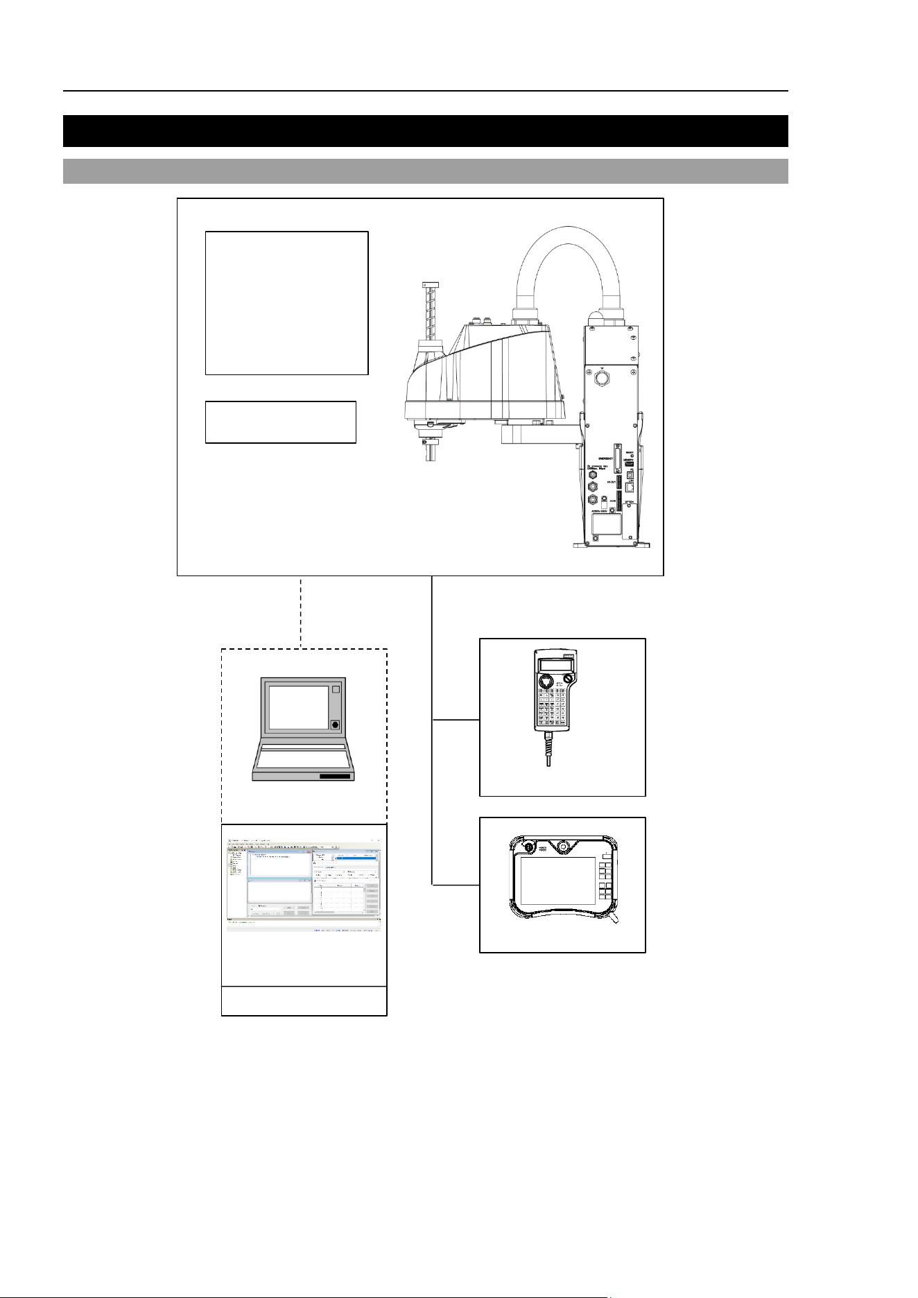
2.1 System Example
T3-B / T6-B
Standard
Standard I/O
Remote I/O
Ethernet
Hand I/O
USB (for save)
USB (for development)
ModBus
Fieldbus
Slave
Option
TP2
TP3
*2
*3
Option: Teaching Pendant
Windows *1
EPSON RC+ 7.0
Software
USB 2.0 or
Ethernet
Option
(I
llustration: T3-B401S)
*1 For system requirements, refer to the following manual:
EPSON RC+ 7.0 User's Guide
*2 Either teaching pendant is available.
*3 If connecting to T3-B/T6-B Manipulator, dedicated convert cable is necessary.
Installation 2. Installation
T-B series Rev.6 5
2.2 Unpacking
Unpacking of the Manipulators and robotic equipment shall be performed by personnel who
has taken robot system training held by us and suppliers and should conform to all national
and local codes.
Please read “Safety Manual” before installing the robot system or before connecting cables
and check the safety considerations.
2.3 Transportation
2.3.1 Transportation Precautions
Transportation of the Manipulators and robotic equipment shall be performed by personnel
who has taken robot system training held by us and suppliers and should conform to all
national and local codes.
Please read “Safety Manual” before installing the robot system or before connecting cables
and check the safety considerations.
2.3.2 Holding Position and Number of People to Transport
Manipulator
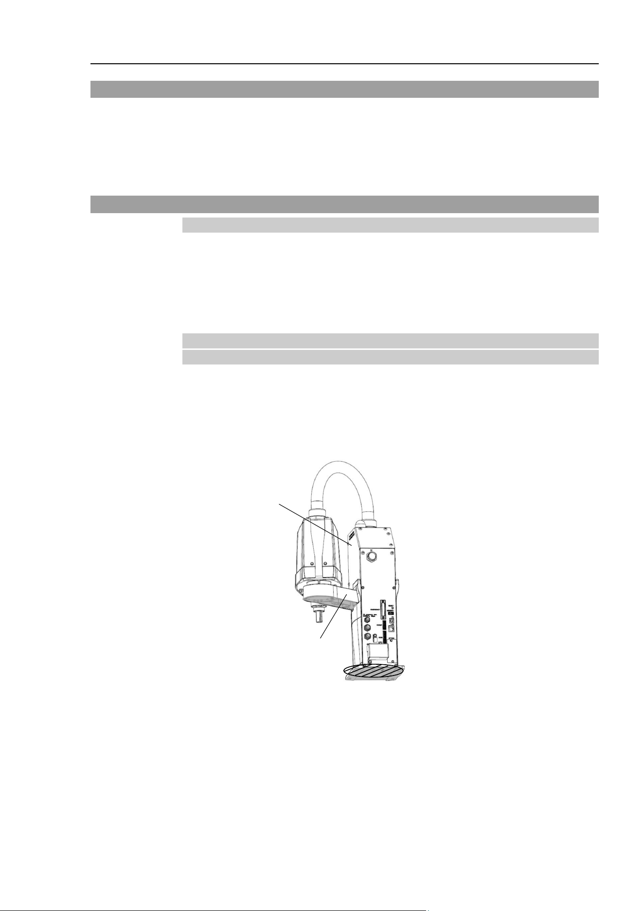
Holding position when transporting: Under arm #1 or bottom of base*
* When holding the bottom of the base by hand, be
very careful not to get your hands or fingers caught.
The number of people to transport: At least two
Prohibited part to hold: Power unit
Power unit
Arm #
1
(Illustration: T3-B401S)

Installation 2. Installation
6 T-B series Rev.6
2.4 Environments and Installation
Installation of the Manipulators and robotic equipment shall be performed by personnel who
has taken robot system training held by us and suppliers and should conform to all national
and local codes.
Please read “Safety Manual” before installing the robot system or before connecting cables
and check the safety considerations.
For details, refer to “T3-B T6-B Manipulator 3. Environments and Installation”.
2.5 Connection to EMERGENCY Connector
Connect a safeguard switch or Emergency Stop switch to the EMERGENCY connector for
safety.
When nothing is connected to the EMERGENCY connector, Controller does not operate
normally.
For details, refer to “T3-B T6-B Manipulator 11. EMERGENCY”.
Installation 3. Power-On
T-B series Rev.6 7
3. Power-On
3.1 Power supply, Power cable, Braker
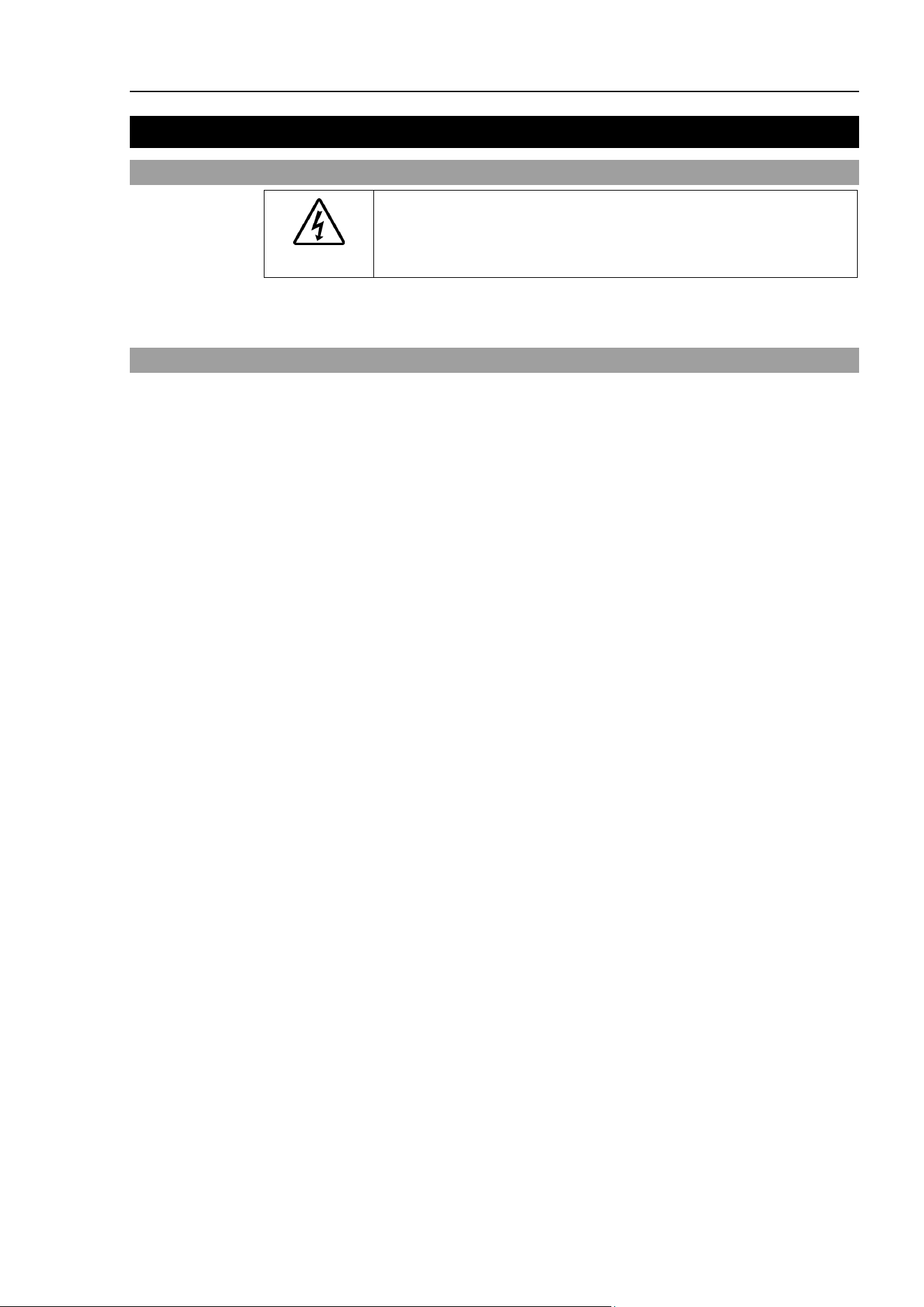
WARNING
There is no power switch on the Manipulator. Right after inserting
power plug to power, the Robot System turns ON.
Be careful about electric shock when inserting power plug.
For power supply, power cable, and braker, refer to “T3-B T6-B Manipulator 3.6 Power
Supply”.
3.2 Power-ON Precautions
Manipulator check:
Before operating the Manipulator, make sure that all parts of the Manipulator are in place
and have no external defects. If an error occurs, stop the operation and contact us.
Shipping bolts and jigs check before turning ON:
Before turning ON the power after installation, be sure to remove the shipping bolts and jigs
from the Manipulator. Turning ON the power while the shipping bolts and jigs are attached
may result in equipment damage to the Manipulator.
Power activation:
Anchor the Manipulator before turning ON the power to or operating the Manipulator.
Turning ON the power to or operating the Manipulator that is not anchored is extremely
hazardous and may result in serious bodily injury and/or severe equipment damage to the
robot system as the Manipulator may fall down.
When supplying the power again:
When supplying the power to the Manipulator again, turn OFF the Controller and wait for
5 seconds or more. Then, turn ON the Manipulator again.
Installation 3. Power-On
8 T-B series Rev.6
3.3 Power On Procedure
(1) Check the EMERGENCY connector connection.
(2) Connect the TP bypass plug to the TP port.
(3) Connect the power cable to the Manipulator.
(4) Connect the power cable to the power supply socket.
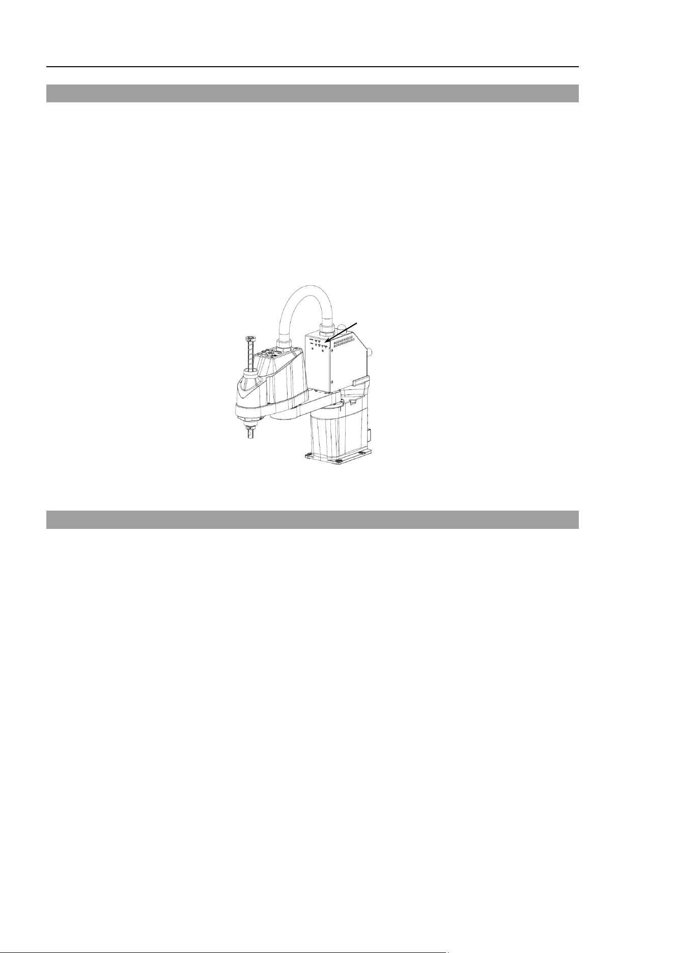
(5) The PROGRAM LED blinks approximately 30 seconds after Controller starts up
normally.
If the ERROR LED is turned ON or blinking, check connection in step (1) to (4) and
turn ON the power again.
If the ERROR LED is still ON or blinking, contact the supplier in your region.
LED
(Illustration: T3-B401S)
3.4 Saving the Factory Default
The manipulator you purchased is set up in the manipulator as the factory default. It is
recommended to save the factory default state of the Controller in case of emergency. For
saving, prepare a USB memory.
For saving the Controller state, refer to “T3-B T6-B Manipulator 8. Memory Port”.
Installation 4. First Step
T-B series Rev.6 9
4. First Step
This section indicates the procedure to install the development PC EPSON RC+, and
execute simple program after connecting the development PC and Manipulator with a USB.
Make sure that the Robot system is installed safely by following the description in “1. Safety”
and “2. Installation”. Then, operate the Robot system in the following procedures.
4.1 Installing EPSON RC+ 7.0 Software
The EPSON RC+ 7.0 software needs to be installed on your development PC.
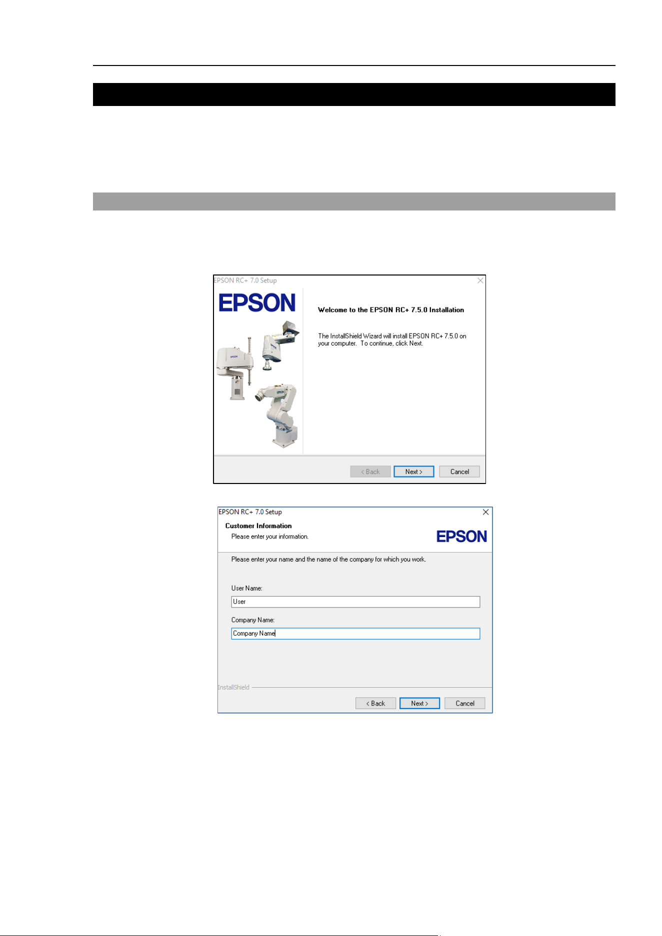
(1) Insert the EPSON RC+ 7.0 Setup DVD in the DVD drive.
(2) The following dialog will be displayed. Click <Next>.
(3) Enter your user name and company name and click <Next>.
Installation 4. First Step
10 T-B series Rev.6
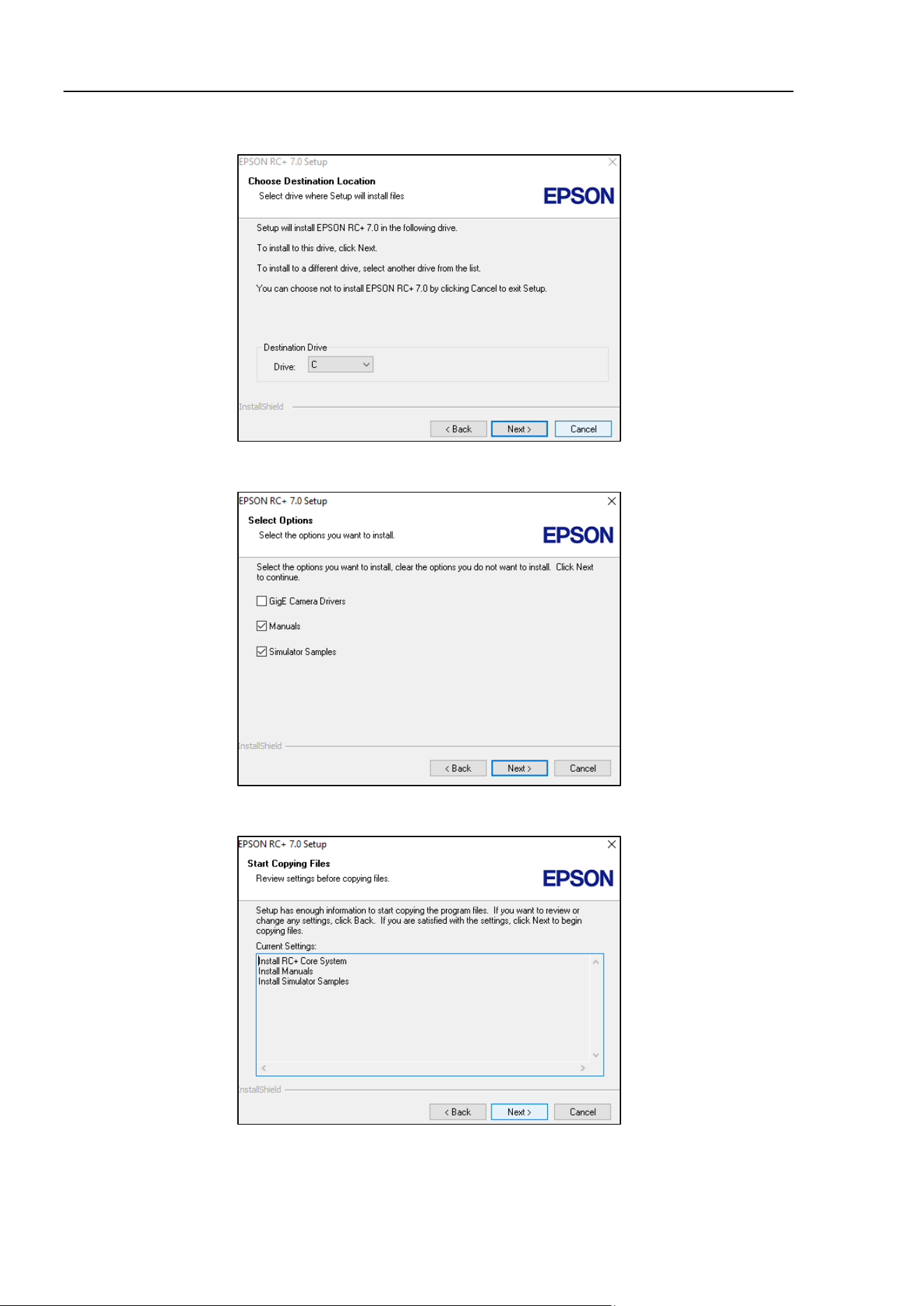
(4) Select the drive where you want to install EPSON RC+ 7.0 and click <Next>.
The installation directory is called EpsonRC70. This cannot be changed.
(5) The dialog for selecting the options to be installed will be displayed.
Check the options you want to install and click <Next>.
(6) The dialog to review the settings will be displayed.
If you are satisfied with the settings, click <Next>.
Installation 4. First Step
T-B series Rev.6 11
(7) If required, install “Windows Installer” on your system. This may take several
minutes.
Manuals are provided in PDF. To refer to the manual, use the pre-installed PDF
viewer in Windows, or install a PDF viewer such as Adobe Acrobat Reader.
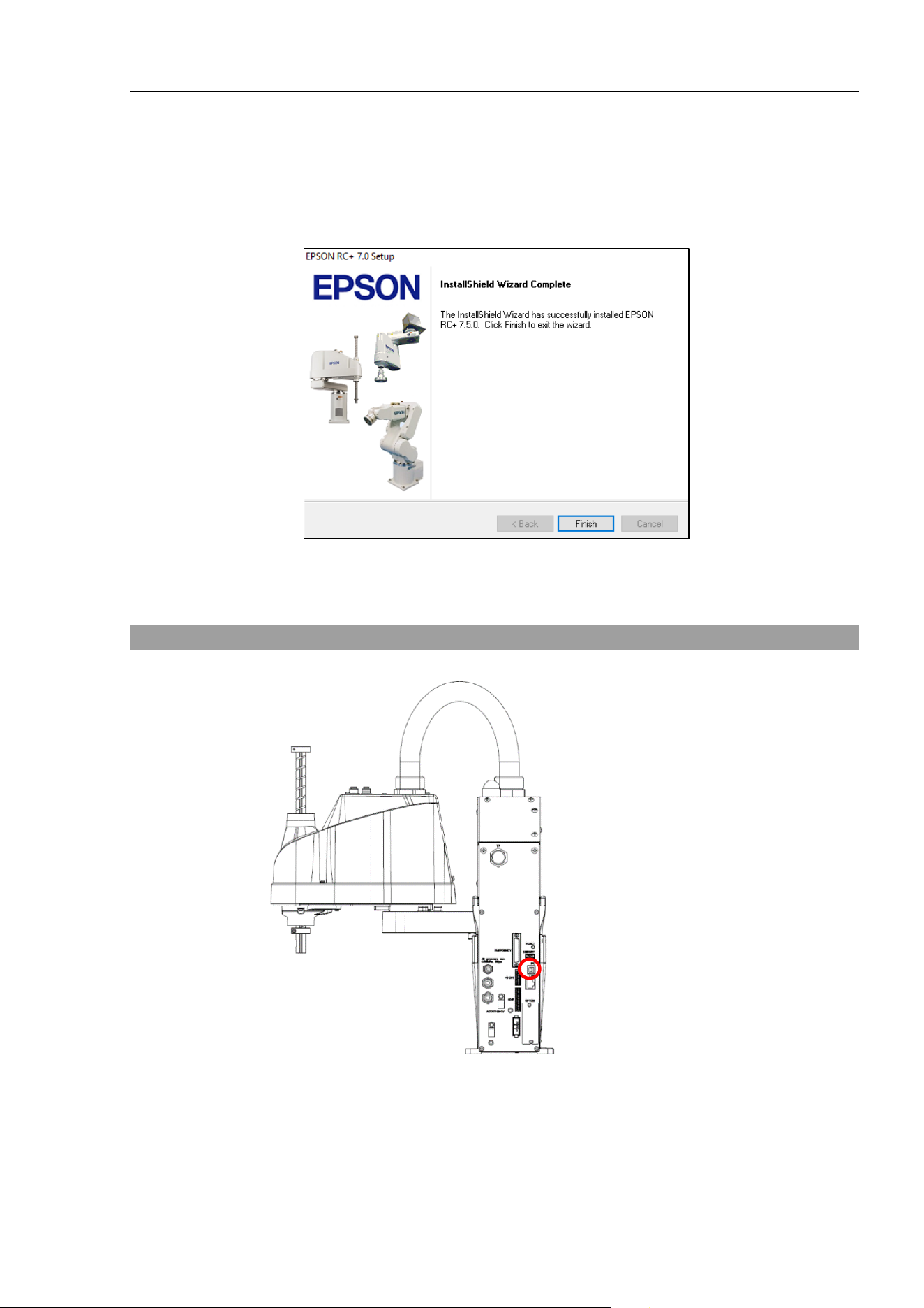
(8) After the installation has completed, restart your computer.
The EPSON RC+ 7.0 software installation is now completed.
When installing RC, an error “Cannot create parser instance.” may occur.
If the error occurs, uninstall RC+ once and execute Microsoft\VC151719.exe in the
DVD and re-install RC+.
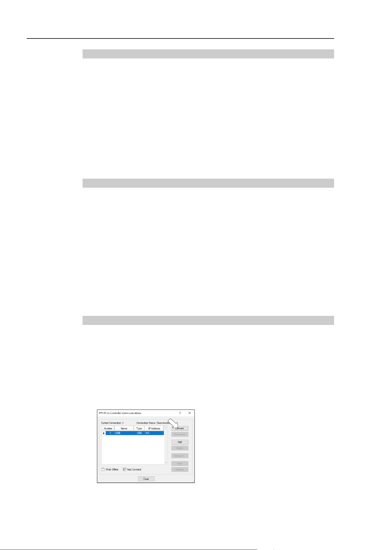
4.2 Development PC and Manipulator Connection
Connect the development PC and the development PC connection port for connection.
(Illustration: T3-B401S)
- For other details of development PC and Manipulator connection, refer to EPSON RC+ 7.0
User’s Guide “PC to Controller Communications Command (Setup Menu)”.
- Be sure to install the EPSON RC+7.0 to the development PC first, then connect the development
PC and Manipulator with the USB cable.
If Manipulator and the development PC are connected without installing the EPSON RC+7.0 to
the development PC, [Add New Hardware Wizard] appears. If this wizard appears, click the
<Cancel> button.
NOTE
NOTE
NOTE
Installation 4. First Step
12 T-B series Rev.6
4.2.1 About Development PC Connection Port
Development PC connection port supports following USB.
- USB2.0 HighSpeed/ FullSpeed (Speed auto selection, or FullSpeed mode)
- USB1.1 FullSpeed
Interface Standard: USB specification Ver.2.0 compliant (USB Ver.1.1 upward compatible)
Connect the Manipulator and development PC by a USB cable to develop the robot system
or set the Manipulator configuration with the EPSON RC+ 7.0 software installed in the
development PC.
Development PC connection port supports hot plugging. Insertion and removal of the cables
while the power of the development PC and the Manipulator are ON is available. However,
the Manipulator stops when the USB cable is removed while the Manipulator and the
development PC are connected.
4.2.2 Precautions
When connecting the development PC and the Manipulator, make sure of the following.
- Connect the development PC and the Manipulator with 5 m or shorter USB cable. Do
not use the USB hub or extension cable.
- Make sure that no other devices except development PC is used for development PC
connection port.
- Use PC or USB cable that supports USB2.0 HighSpeed mode to operate in USB2.0
HighSpeed mode.
- Do not pull or bend the cable strongly.
- Do not apply excessive force to the connector.
- When development PC and the Manipulator is connected, do not insert or remove other
USB devices from the development PC. Connection with the Manipulator may
disconnect.
4.2.3 Software Setup and Connection Check
The following is the steps of connecting the development PC and the Manipulator.
(1) Make sure that the EPSON RC+ 7.0 is installed on the Manipulator connected to the
development PC. (Install the software when it is not installed.))
(2) Connect the development PC and the Manipulator by the USB cable.
(3) Turn ON the Manipulator.
(4) Start the software EPSON RC+ 7.0.
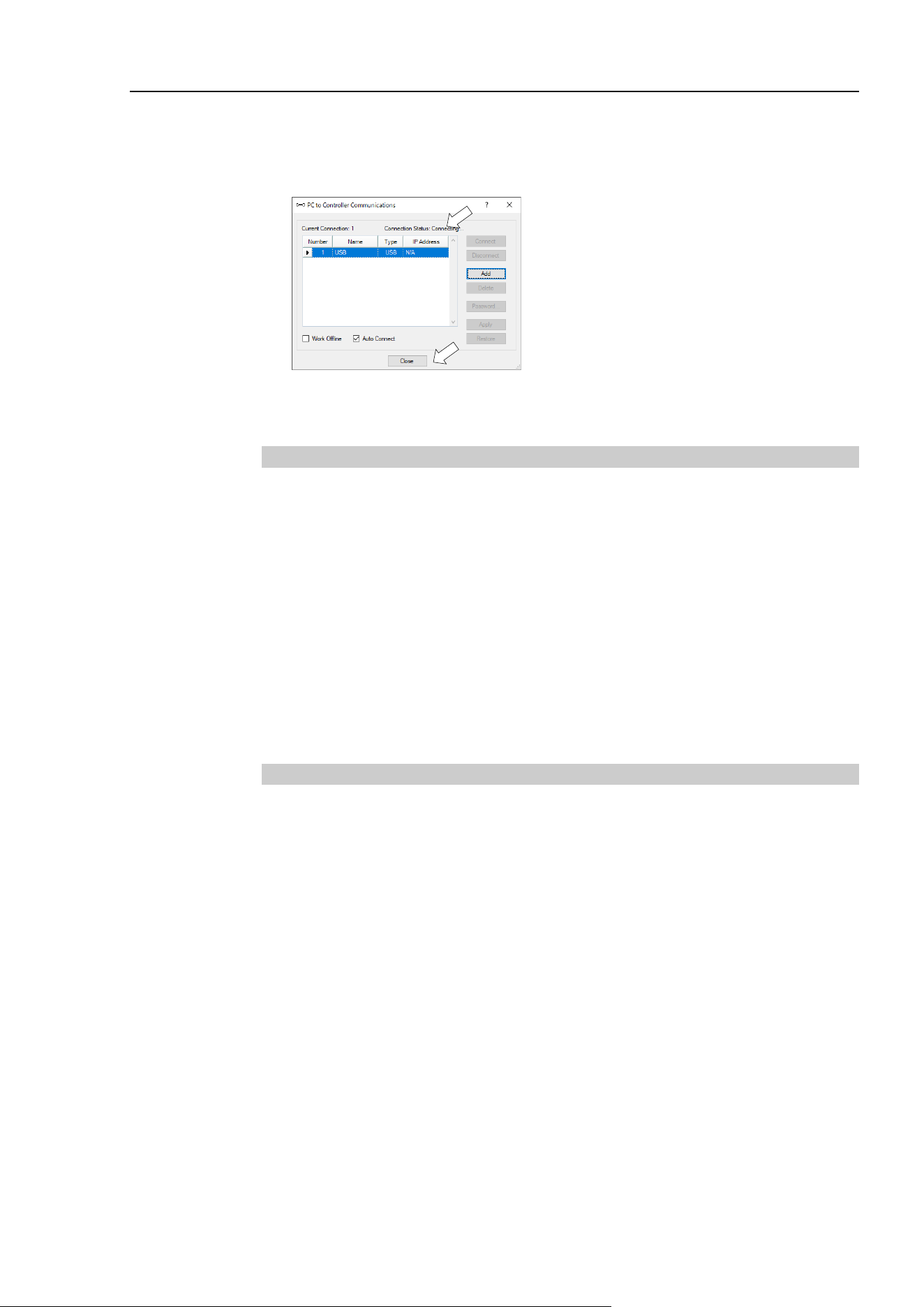
(5) Select the EPSON RC+ 7.0 menu-[Setup]-[PC to Controller Communications] to
display the [PC to Controller Communications] dialog.
(6) Select the “No.1 USB” and click the <Connect> button.
Installation 4. First Step
T-B series Rev.6 13
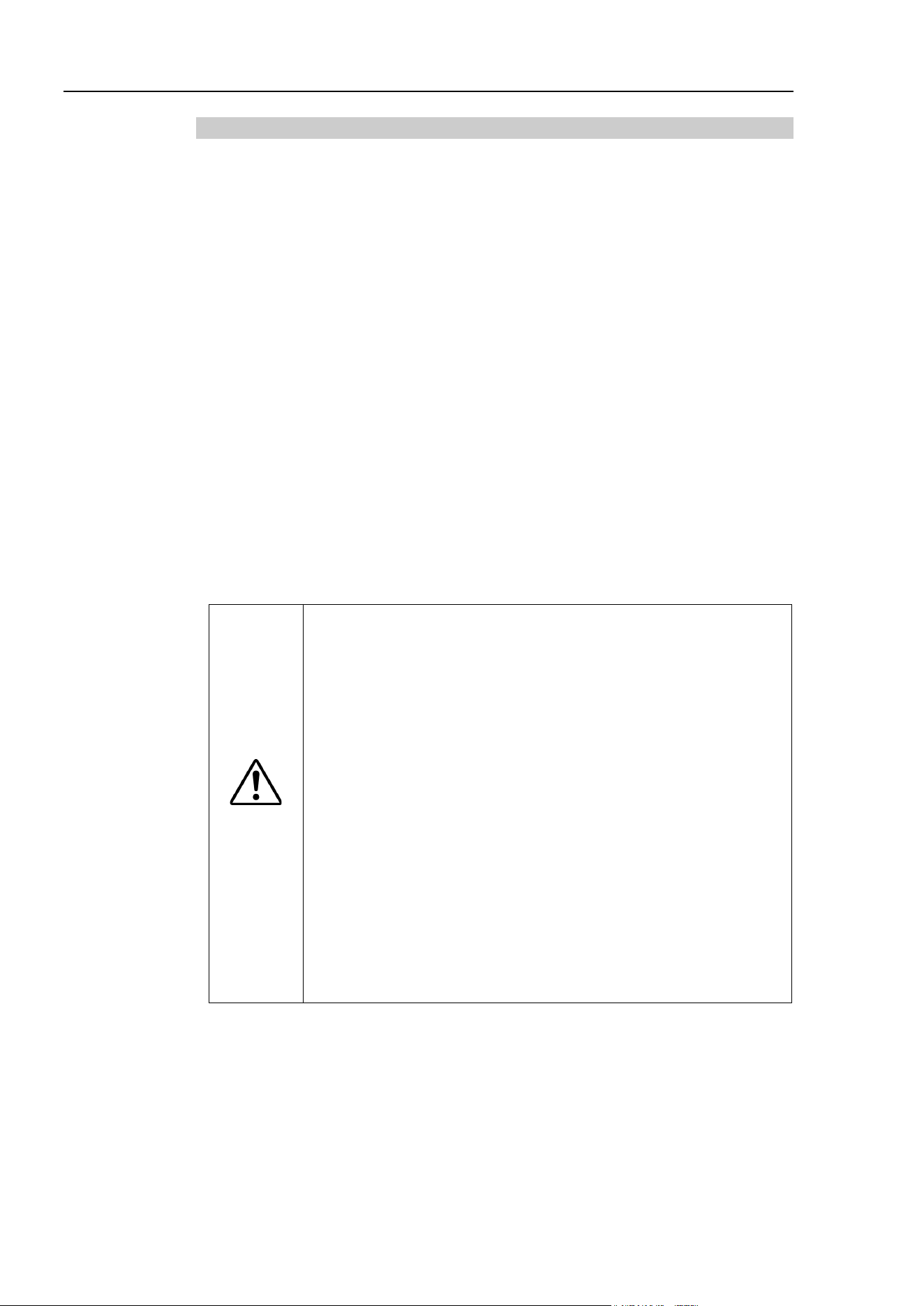
(7) After development PC and the Manipulator connection is completed, “Connected” is
displayed in the [Connection status:]. Make sure that “Connected” is displayed and
click the <Close> button to close the [PC to Controller Communications] dialog.
Connection of the development PC and the Manipulator is completed. Now robot system
can be used from EPSON RC+ 7.0.
4.2.4 Backup the Initial Condition of the Manipulator
Backup the Manipulator data configured before shipment.
Project and system configuration backup procedure:
(1) From the [Project] menu, select [Copy].
(2) Change the [Destination Drive] to an arbitrary drive.
(3) Click <OK>. The project will be copied to the external media.
(4) From the [Tools] menu, select [Controller].
(5) Click on the <Backup Controller> button.
(6) Select the arbitrary drive.
(7) Click <OK>. The system configuration will be backed up on the external media.
4.2.5 Disconnection of Development PC and Manipulator
Disconnection of the development PC and the Manipulator is indicated.
(1) Select the EPSON RC+ 7.0 menu-[Setup]-[PC to Controller Communications] to
display the [PC to Controller Communications] dialog.
(2) Click the <Disconnect> button.
Manipulator and the development PC is disconnected and USB cable can be removed.
If the USB cable is removed while the Manipulator and the development PC are connected,
the Manipulator stops. Be sure to click the <Disconnect> button in the [PC to Controller
Communications] dialog before removing the USB cable.
NOTE
Installation 4. First Step
14 T-B series Rev.6
4.2.6 Moving the Manipulator to Initial Position
Manipulator can be operated by the following methods other than creating and executing
the program.
Manual operation
Jog motion by the Teach Pendant
Command execution from the EPSON RC+
Jog motion from the EPSON RC+
This section explains about following methods.
A: Manual operation
B: Command execution from the EPSON RC+
C: Jog motion from the EPSON RC+
A: Manual operation
Manually move the Manipulator that is free from the servo control.
You can move Joint #3 by hand while the break release switch on the Manipulator is
being pressed with the Controller ON.
Joints #1, #2, and #4 can be moved by hand.
Also, you can move the Manipulator manually by releasing the solenoid brake from the
command window of the EPSON RC+.
CAUTION
■
Normally, release the brake of joints one by one. Take extra care
if you need to release the brakes of two or more joints
simultaneously. Releasing the brakes of two or more joints
simultaneously may result in hands or fingers being caught
and/or equipment damage to or malfunction of the Manipulator
as the arms of the Manipulator may move in unexpected
directions.
■
Be
careful of the arm falling when releasing the brake. While the
brake is being released, the Manipulator’s arm falls by its own
weight. The arm falling may result in hands or fingers being
caught and/or equipment damage to or malfunction of the
Manipulator.
■
Before releasing the brake, be sure to keep the Emergency Stop
switch handy so that you can immediately press the Emergency
Stop switch. Otherwise, you cannot immediately stop the arm
falling due to an erroneous operation. The arm falling may cause
eq
uipment damage to and/or malfunction of the Manipulator.
(1) Start EPSON RC+ 7.0.
Double click the <EPSON RC+ 7.0> icon on the desktop.
(2) Open the command window.
EPSON RC+ 7.0 menu-[Tool]-[Command Window]
(3) Execute the following command in [Command Window].
>Reset
>Brake Off,[Arm # (1 to 4) whose brake will be released]
Execute the following command to turn on the brake again.
>Brake On,[Arm # (1 to 4) whose brake will be turned on]
Installation 4. First Step
T-B series Rev.6 15
B: Command execution from the EPSON RC+
Move the Manipulator by exciting the Manipulator motors and executing the command.
Following explains the example of moving all joints to the 0 pulse positions by
specifying the pulse for each joint.
(1) Start the EPSON RC+ 7.0.
Double click the <EPSON RC+ 7.0> icon on the desktop.
(2) Open the command window.
EPSON RC+ 7.0 menu-[Tools]-[Command Window]
(3) Execute the following command in [Command Window].
>Motor On
>Go Pulse (0,0,0,0)
For position and posture of Manipulator at 0 pulse position, refer to “T3-B T6-B
Manipulator 5. Motion Range” in the Manipulator manuals.
C: Jog motion from the EPSON RC+
Move the Manipulator by exciting the motors and operating from the Jog & Teach
window of the EPSON RC+.
(1) Start the EPSON RC+ 7.0.
Double click the <EPSON RC+ 7.0> icon on the desktop.
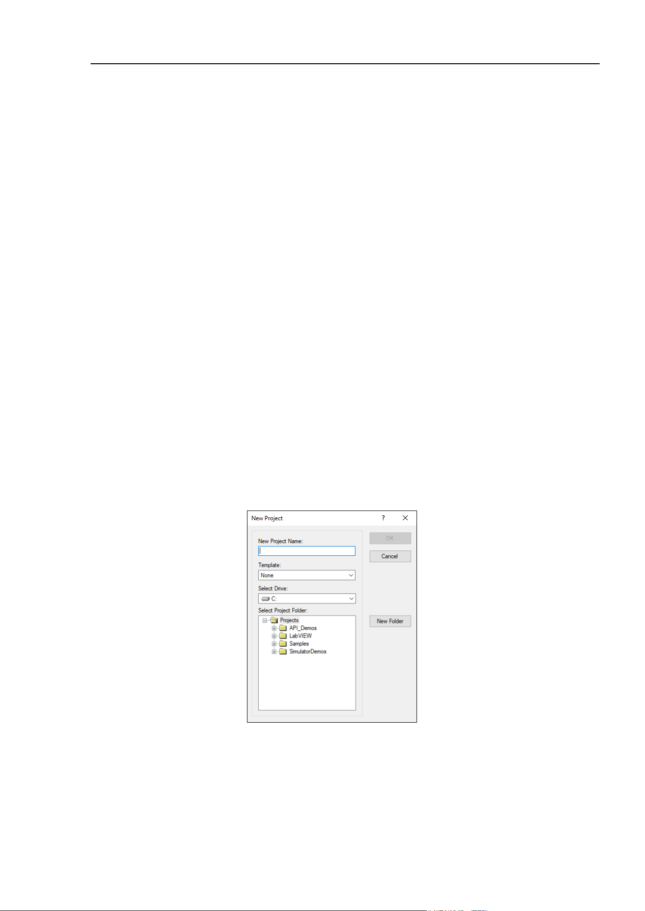
(2) Create a new project.
1. Select [New] from the [Project] Menu. The [New Project] dialog box will be
displayed.
2. Type a project name in the [New Project Name] box. (e.g. FirstApp)
3. Click the <OK> button to create the new project.
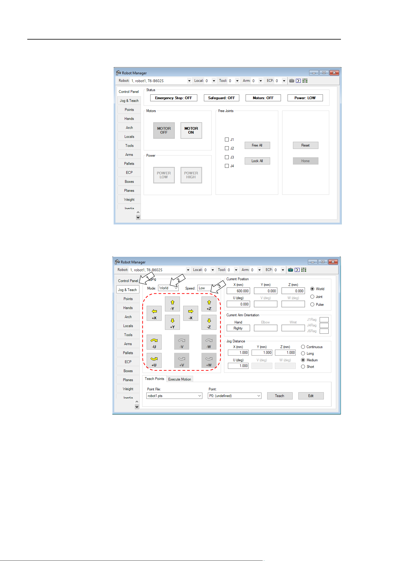
(3) Open the Robot Manager.
EPSON RC+ 7.0 menu-[Tools]-[Robot Manager].
Installation 4. First Step
16 T-B series Rev.6
(4) Turn ON the motors.
Check that the [Control Panel] tab is open. Click the <MOTOR ON> button.
(5) Move the Manipulator with Jog motion.
1. Select [Jog & Teach] tab.
2. Select “Joint” in [Jogging]-<Mode>.
3. Move the Manipulator by joint by clicking J1-J4 jog keys.
Manipulator can be moved by setting to other modes or setting the jog
distance.
Installation 4. First Step
T-B series Rev.6 17
4.3 Writing Your First Program
After installing the Manipulator and EPSON RC+ 7.0 software on your PC, follow the instructions
below to create a simple application program so that you will become more familiar with the EPSON
RC+ 7.0 development environment.
1. Start EPSON RC+ 7.0
Double-click the EPSON RC+ 7.0 icon on the desktop.
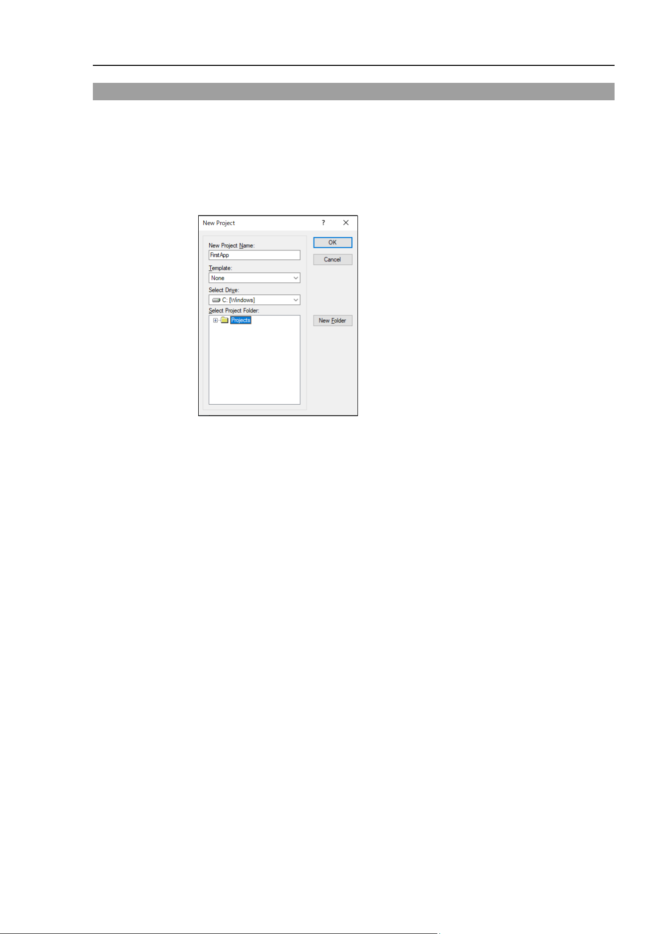
2. Create a new project
(1) Select [New] from the [Project] Menu. The [New Project] dialog box will be displayed.
(2) Type a project name in the [New Project Name] box. (e.g. FirstApp)
(3) Click the <OK> button to create the new project.
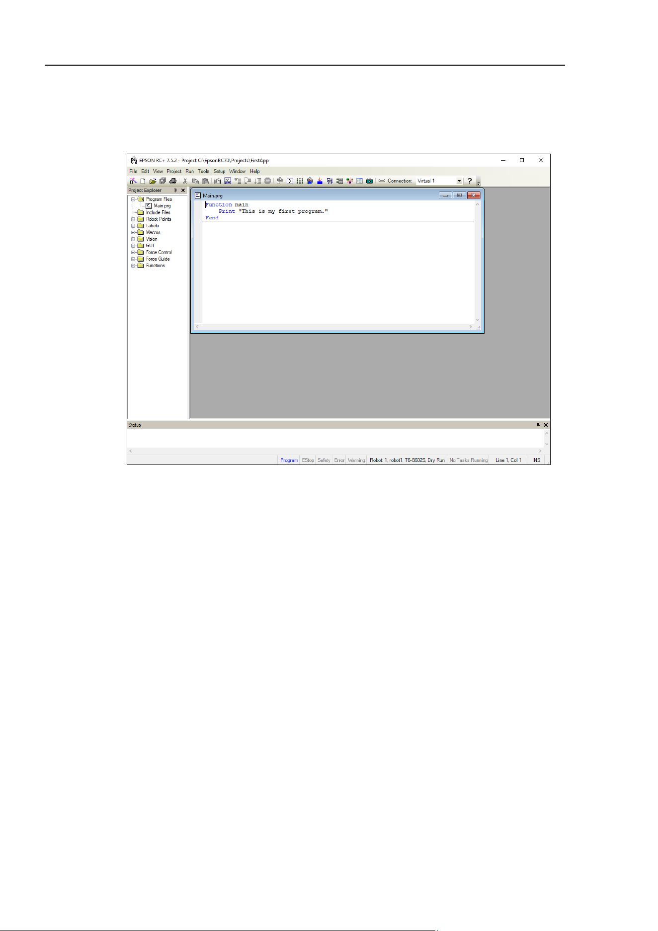
When the new project is created, a program called Main.prg is created.
The window titled Main.prg will be displayed with a cursor flashing in the upper left
corner. Now you are ready to start entering your first program.
Installation 4. First Step
18 T-B series Rev.6
3. Edit the program
Type the following program lines in the Main.prg edit window.
Function main
Print "This is my first program"
Fend
Installation 4. First Step
T-B series Rev.6 19
4. Run the program
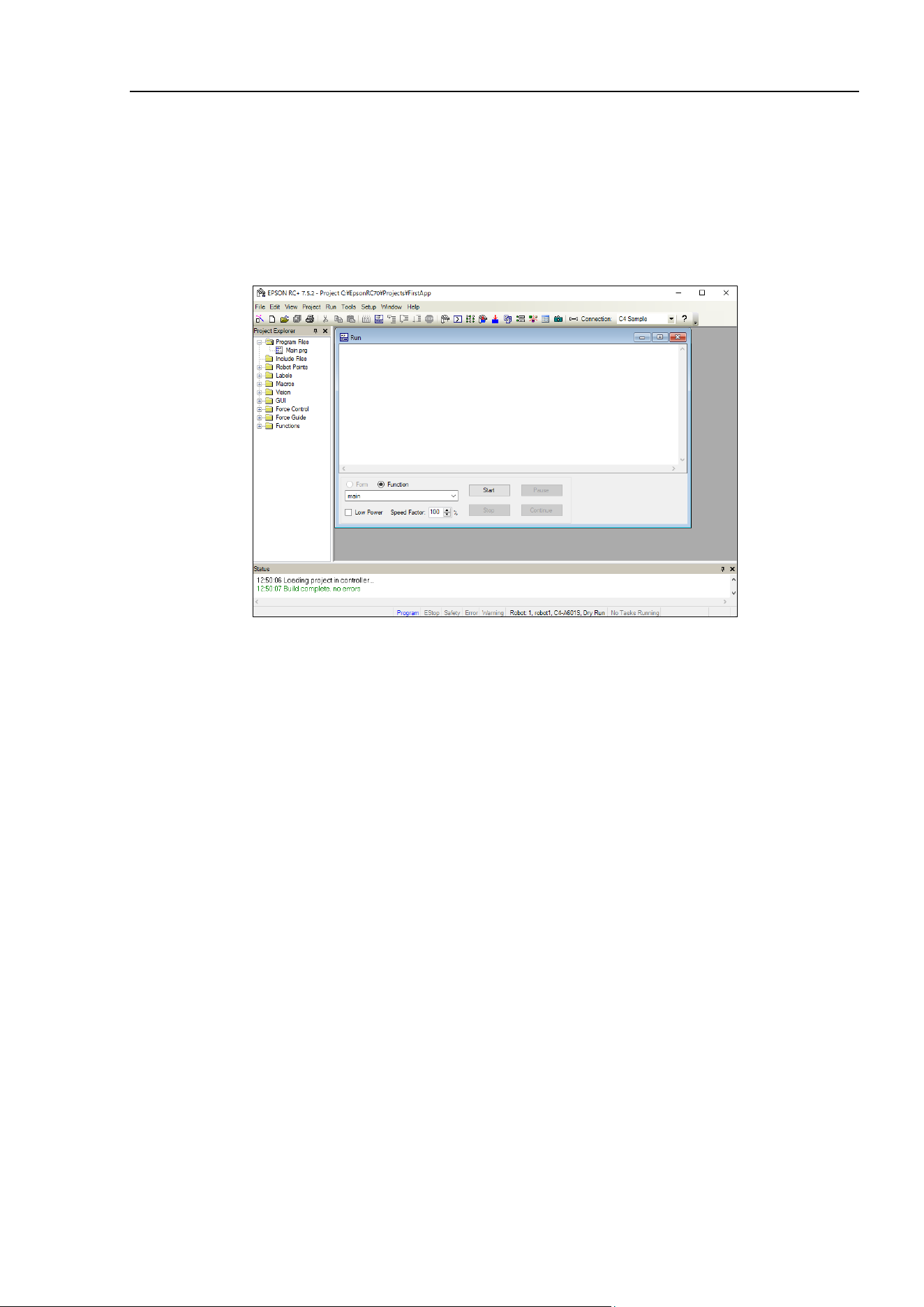
(1) Press F5 to run the program. (F5 is the hot key for the [Run Window] selection of the
[Run] Menu). You will see the Status window located at the bottom of the main window
showing the build operation status.
(2) During project build, your program is compiled and linked. Then communications is
established with the Manipulator and project files are sent to the Controller. If there are no
errors during build, the Run window will appear.
(3) Click the <Start> button on the Run window to run the program.
(4) The tasks like the following will be displayed in the status window.
19:32:45 Task main started
19:32:45 All tasks stopped
On the Run window, you will see the output of the print statement.
Installation 4. First Step
20 T-B series Rev.6
Now let’s teach some Manipulator points and create a program to move the Manipulator.
Teaching described in this procedure should be done outside the safeguard.
5. Teach robot points
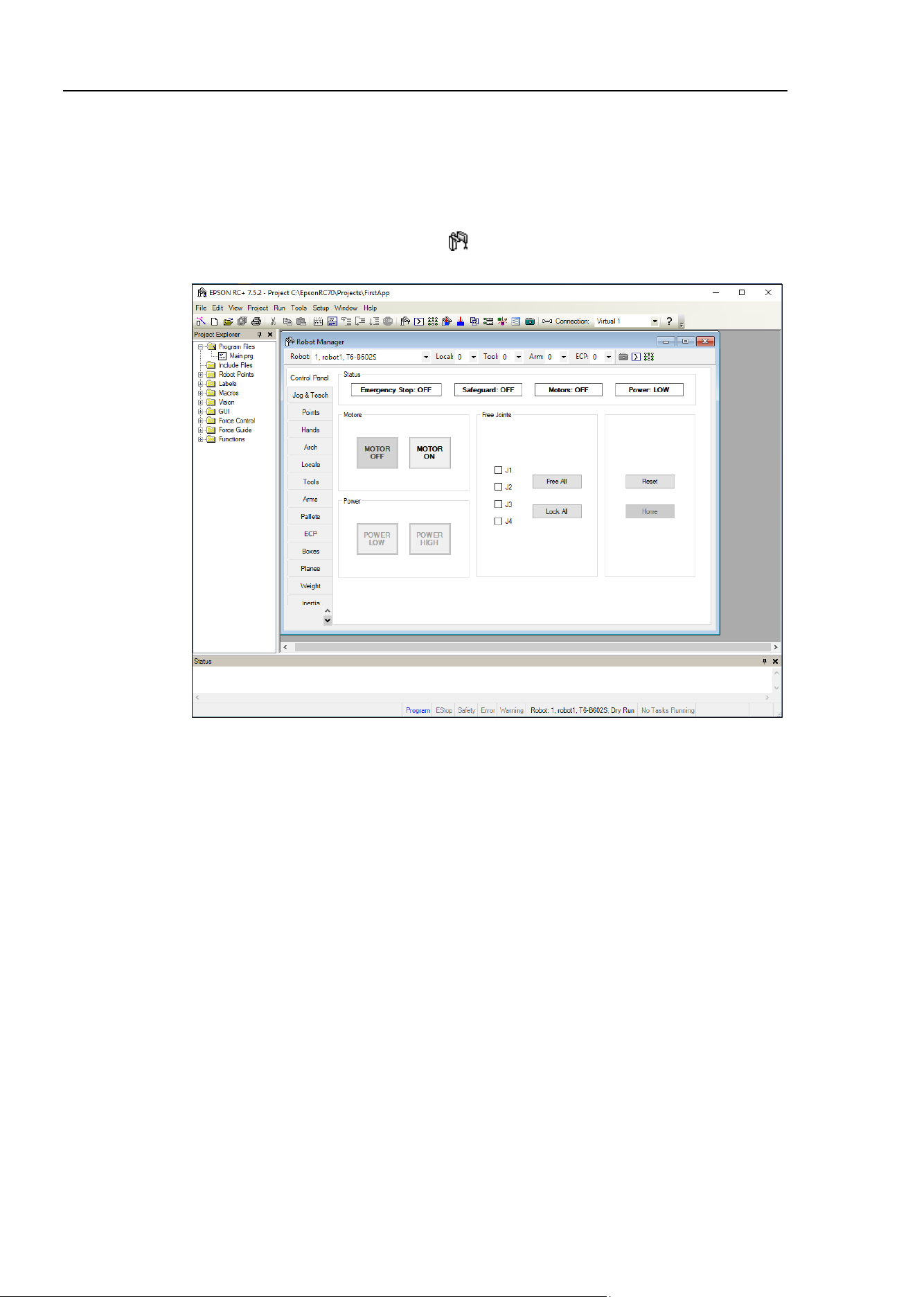
(1) Make sure that it is safe to operate the Manipulator.
Click the <Robot Manager> button on the toolbar to display the [Robot Manager]
window.
(2) Click the [Control Panel] tab. Then, click the <MOTOR ON> button to turn on the
Manipulator motors. You will be prompted to confirm the operation.
(3) Click the <Yes> button to continue.
NOTE
Installation 4. First Step
T-B series Rev.6 21
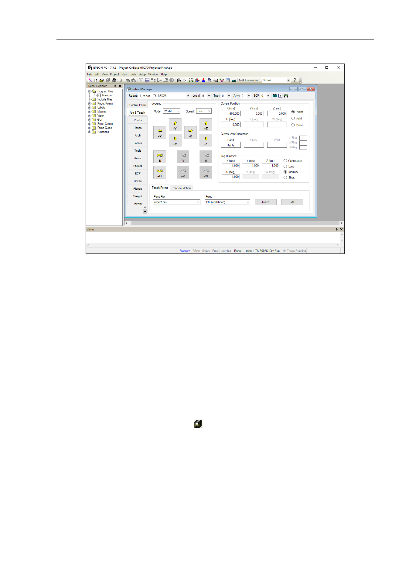
(4) Click the [Jog & Teach] tab.
(5) Click the <Teach> button in the lower right corner to teach point P0. You will be prompted
for a point label and description.
(6) Click the <+Y> jog button to jog the robot in +Y direction. Hold down the button to keep
jogging. Move the Manipulator until it reaches the middle of the work envelope.
(7) Click the <-Z> button to lower the Z axis of the Manipulator.
(8) Select “P1” in the [Point (P)] dropdown list which is next to the <Teach> button. The
current point is set to P1.
(9) Click the <Teach> button. You will see a confirmation message to teach the point.
(10)Click the <Yes> button.
(11)Click the <+X> button to jog the Manipulator in the +X direction.
(12)Select “P2” in the [Point (P)] dropdown list which is next to the <Teach> button. The
current point is set to P2.
(13)Click the <Teach> button. You will see a confirmation message to teach the point.
(14)Click the <Yes> button.
(15)Click the <Save Project> toolbar button to save the changes.

Installation 4. First Step
22 T-B series Rev.6
6. Modify the program to include Manipulator motion commands
(1) Insert three new Go statements into the Main.prg program as shown below:
Function main
Print "This is my first program."
Go P1
Go P2
Go P0
Fend
(2) Press F5 to display the Run window.
(3) Click the <Start> button to execute the program.
The Manipulator will move to the points you taught.
7. Modify the program to change speed of Manipulator motion commands
(1) Insert the Power, Speed, and Accel commands as shown in the program below:
Function main
Print "This is my first program."
Power High
Speed 20
Accel 20, 20
Go P1
Go P2
Go P0
Fend
(2) Press F5 to display the Run window.
(3) Click the <Start> button to execute the program.
The Manipulator will move to each of the points you taught at 20% speed, acceleration,
and deceleration. The Power High statement executes the program to operate the robot
with increased speed and acceleration, and deceleration.
8. Backup the project and system configuration
Even though this is only a sample project, we will backup the project and Manipulator
configuration. Backup can be done easily with EPSON RC+ 7.0. It is important that you keep
regular backups of your applications on an external media such as a USB memory key.
Follow the steps below to back up the project and system configuration:
(1) Select the EPSON RC+ 7.0 menu - [Project] - [Copy].
(2) Change the [Destination Drive] to an arbitrary drive.
(3) Click <OK>. The project will be copied to the external media.
(4) Select the EPSON RC+ 7.0 menu - [Tools] - [Controller].
(5) Click on the <Backup Controller> button.
(6) Select the arbitrary drive.
(7) Click <OK>. The system configuration will be backed up on the external media.

Installation 5. Second Step
T-B series Rev.6 23
5. Second Step
After operating the robot system as instructed in 4. First Step, setup other functions as
necessary.
This section shows the manuals which contains information of necessary settings and setting
procedure.
5.1 Connection with External Equipment
5.1.1 Remote Control
EPSON RC+ 7.0 User’s Guide “Remote Control”
“T3-B T6-B Manipulator 14. I/O Remote Set Up”
I/O
EPSON RC+ 7.0 User’s Guide “I/O Setup”
“T3-B T6-B Manipulator 12. Standard I/O Connector”
“T3-B T6-B Manipulator 13. Hand I/O Connecter”
Fieldbus I/O (Option)
ROBOT CONTROLLER Option Fieldbus I/O Board
5.1.2 Ethernet
EPSON RC+ 7.0 User’s Guide
“1.9 Security for Controller Ethernet Connection”
“1.10 Security for Compact Vision CV2-A Ethernet Connection”
“1.11 Security for Feeder Ethernet Connection”
“4.3.3 Ethernet Communication”
“T3-B T6-B Manipulator 9. LAN (Ethernet) Port”
5.2 Ethernet Connection of Development PC and Manipulator
EPSON RC+ 7.0 User’s Guide
“1.9 Security for Controller Ethernet Connection”
“1.10 Security for Compact Vision CV2-A Ethernet Connection”
“1.11 Security for Feeder Ethernet Connection”
“4.3.3 Ethernet Communication”
“T3-B T6-B Manipulator 9. LAN (Ethernet) Port”
5.3 Connection of Option Teaching Pendant
“T3-B T6-B Manipulator 10. TP Port”
ROBOT CONTROLLER Option Teach Pendant TP2
“Function & Installation: 3. Installation”
ROBOT CONTROLLER Option Teach Pendant TP3
“Function & Installation: 3. Installation”

Installation 5. Second Step
24 T-B series Rev.6

T3-B T6-B Manipulator
This volume contains information for setup and operation of the Manipulators.
Please read this volume thoroughly before setting up and operating the Manipulators.

T3-B T6-B Manipulator 1. Safety
T-B series Rev.6 27
1. Safety
Unpacking and transportation of the Manipulators and robotic equipment shall be performed
by personnel who has taken robot system training held by us and suppliers and should
conform to all national and local codes.
Please read this manual and other related manuals before installing the robot system or
before connecting cables.
Keep this manual handy for easy access at all times and reread it when you find anything
unclear.
1.1 Conventions
Important safety considerations are indicated throughout the manual by the following
symbols. Be sure to read the descriptions shown with each symbol.
WARNING
This symbol indicates that a danger of possible serious injury or
death exists if the associated instructions are not followed
properly.
WARNING
This symbol indicates that a danger of possible serious injury
caused by electric shock exists if the associated instructions are
not followed properly.
CAUTION
This symbol indicates that a danger of possible harm to people
or physical
damage to equipment and facilities exists if the
associated instructions are not followed properly.
T3-B T6-B Manipulator 1. Safety
28 T-B series Rev.6
1.2 Design and Installation Safety
This product is intended for transporting and assembling parts in a safely isolated area.
Design and installation of robot system shall be performed by personnel who has taken robot
system training held by us and suppliers.
To ensure safety, a safeguard must be installed for the robot system. For details on the
safeguard, refer to the 1.5 Safeguard.
The following items are safety precautions for design personnel:
WARNING
■
Personnel who design and/or construct the robot system with this product must
read
“Safety Manual”. Designing and/or constructing the robot system without
understanding the safety requ
irements is extremely hazardous, and may result in
serious bodily injury and/or severe equipment damage to the robot system.
■
The robot
system must be used within the environmental conditions described in
their respective manuals. This product has
been designed and manufactured
strictly for use in a normal indoor environment. Using the product in an
environment that exceeds the specified environmental conditions may not only
shorten the life cycle of the product but may also cause serious safety pro
blems.
■
The robot system must be used within the installation requirements described in
the manuals.
Using the robot system outside of the installation requirements may
not only shorten the life cycle of the product but also cause serious safety
problems.
■
When designing or installing a robot system, wear at least the following protective
gear. Working without protective gear may
cause serious safety problems.
Work clothes suitable for work
Helmet
Safety shoes
Further precautions for installation are described in “3. Environment and Installation”.
Please read this chapter carefully to understand safe installation procedures before installing
the robots and robotic equipment.
T3-B T6-B Manipulator 1. Safety
T-B series Rev.6 29
Strength of the Ball Screw Spline
If a load exceeding the allowable value is applied to the ball screw spline, it may not work
properly due to deformation or breakage of the shaft. If the ball screw spline is applied the
load exceeding the allowable value, it is necessary to replace the ball screw spline unit.
The allowable loads differ depending on distance where the load is applied to.
For calculating the allowable load, see the calculation formula below.
[Allowable bending moment]
T3-B: M=13,000 N
∙
mm
T6-B: M=27,000 N
∙
mm
Example: If 100 N load is applied
at 200 mm from
the end of the spline nut
[Moment]
M=F
∙
L
=
200
∙
100
=
20,000 N
∙
mm
End of the
spline nut
F
L
1.3 Operation Safety
The following items are safety precautions for qualified Operator personnel:
WARNING
■
Please carefully read “
Safety Manual ”. Operating the robot system without
understanding the safety precautions is extremely hazardous and may result in
serious bodily injury and/or severe equipment damage to the robot
system.
■
Do not enter the operating area of the Manipulator while the power to the robot
system is turned ON.
Entering the operating area with the power ON is extremely
hazardous and may cause serious safety problems as the Manipulator may move
even if it seems to be stopped.
■
Before operating the robot system, make sure that no one is inside the
safeguarded area. The robot system can be operated in
the mode for teaching
even when someone is inside the safeguarded area.
The motion of the Manipulator is always in restricted (low
speed and low power)
status to secure the safety of an operator. However, operating the robot system
while someone is inside the safeguarded area is extremely hazardous and may
result in serious safety problems in case that the Manipulator moves unexpected
ly.
■
Immediately press the Emergency Stop switch whenever the Manipulator moves
abnormally while the robot system is operated.
Continuing the operation while the
Manipulator moves abnormally is extremely hazardous and may result in serious
bodily injur
y and/or severe equipment damage to the robot system.
T3-B T6-B Manipulator 1. Safety
30 T-B series Rev.6
WARNING
■
To shut off power to the robot system, disconnect the power plug from the power
source. Be sure to connect the AC power cable to a power receptacle.
DO NOT connect it directly to a factory power source.
CAUTION
■
Whenever possible, only one person should operate the
robot system. If it is
necessary to operate the robot system with more than one person, ensure that all
people involved communicate with each other as to what they are doing and take
all necessary safety precautions.
■
Joint #1, #2, and #4:
If the joints are operated
repeatedly with the operating angle less than 5 degrees,
they may get damaged early because the bearings are likely to cause oil film
shortage in such situation. To prevent early breakdown, move
each joint larger
than 50 degrees
for about once an hour.
Joint #3:
If the up
-and-down motion of the hand is less than 10 mm, move the joint a half of
the maximum stroke for
about once an hour.
■
Oscillation (resonance) may
occur continuously in low speed Manipulator motion
(Speed:
approx. 5 to 20%) depending on combination of Arm orientation and end
effector load. Oscillation arises from natural oscillation frequency of the Arm and
can be controlled by following measures.
Changing Manipulator speed
Changing the teach points
Changing the end effector load
■
Manipulator
may be heated due to motor heat etc. Do not touch the Manipulator
until temperature falls. After confirming that the temperature of the Manipulator
falls and is not hot when you touch it. Then perform teaching or maintenance.

T3-B T6-B Manipulator 1. Safety
T-B series Rev.6 31
1.4 Emergency Stop
If the Manipulator moves abnormally during operation, immediately press the Emergency
Stop switch. Pressing the Emergency Stop switch immediately changes the manipulator to
deceleration motion and stops it at the maximum deceleration speed.
Avoid pressing the Emergency Stop switch unnecessarily while the Manipulator is running
normally.
- The Manipulator may hit the peripheral equipment.
When you press the Emergency Stop switch, the operating trajectory until the robot
system stops is different from that in normal operation.
- The life of the brakes will be shortened.
The brakes are locked and the brake friction plate is worn.
Normal brake life cycle: About 2 years (when the brakes are used 100 times/day)
However, the rough normal relay life is approximately 20,000 times. If you press the
emergency stop switch unnecessarily, the life of the relay will be shortened.
- Impact is applied on the reduction gear unit, and it may result in the short life of the
reduction gear unit.
To place the system in emergency mode during normal operation, press the Emergency Stop
switch when the Manipulator is not moving.
Refer to “11. EMERGENCY” for instructions on how to wire the Emergency Stop switch
circuit.
Do not turn OFF the Controller while the Manipulator is operating.
If you attempt to stop the Manipulator in emergency situations, make sure to stop the
Manipulator using the E-STOP of the Controller.
If the Manipulator is stopped by turning OFF the power while it is operating, following
problems may occur.
Reduction of the life and damage of the reduction gear unit
Position gap at the joints
In addition, if the manipulator was forced to be turned OFF by blackouts and the like while
the Manipulator is operating, make sure to check the following points after power restoration.
Whether or not the reduction gear is damaged
Whether or not the joints are in their proper positions
If there is a position gap, perform calibration by referring to “T-B series Maintenance
Manual 17. Calibration”. Also, the same troubles may occur if an error occurs and the
Manipulator stops in emergency during the operation. Check the Manipulator condition and
perform calibration if necessary.
Before using the Emergency Stop switch, be aware of the following.
- The Emergency Stop (E-STOP) switch should be used to stop the Manipulator only in
case of emergencies.
- To stop the Manipulator operating the program except in emergency, use Pause (halt)
or STOP (program stop) commands
Pause and STOP commands do not turn OFF the motors. Therefore, the brake does not
function.
- For the Safeguard system, do not use the circuit for E-STOP.

T3-B T6-B Manipulator 1. Safety
32 T-B series Rev.6
To check brake problems, refer to “Regular Inspection 1. T3-B T6-B Manipulator Regular
Inspection”.
Test pulse cannot be used with the emergency stop input of this model.
Stopping distance in emergency
The Manipulator in operation cannot stop immediately after the Emergency Stop switch is
pressed. In addition, stopping time and stopping distance vary by following factors:
Hand weight WEIGHT Setting ACCEL Setting
Workpiece weight SPEED Setting Posture etc.
For stopping time and stopping distance of the Manipulator, refer to “Appendix B: Stopping
Time and Stopping Distance in Emergency”.
NOTE
T3-B T6-B Manipulator 1. Safety
T-B series Rev.6 33
1.5 Safeguard
To ensure safe operation, install a safety system using safety doors, light curtains, safety
floor mats, etc.
When a closed safeguard is open during robot motion, the safeguard interlock function
operates. The robot stops immediately and enters into pause state. Then, all robot motors are
turned OFF. The descriptions below explain how the safeguard input works.
Safeguard open
: The robot stops immediately, motors are turned OFF, and further
operation is impossible until either the safeguard is closed or TEACH
or TEST mode is turned ON and the enable circuit is engaged.
Safeguard closed
: The robot can automatically operate in unrestricted (high power) state.
Do not open the safeguard unnecessarily while motor is ON. Frequent safeguard inputs
affect the life of the relay.
Rough normal relay life: Approximately 20,000 times
For the safeguard, do not use the E-STOP circuit.
For details of wiring instructions, refer to “11. EMERGENCY”.
Test pulse cannot be used with the safeguard input of this model.
WARNING
■
The EMERGENCY connector on the Manipulator has a safeguard input circuit to
connect the safety device interlock switch. To protect operators working near the
robot, be sure to connect the interlock switch and make sure that it works
properly.
■
The time to stop the robot and the stopping distance by the safeguard interlock
function will change depending on the conditions of use. Be sure to confirm that
safety is ensured according to the installation environment of the robot.
Stopping distance when the safeguard is opened
The Manipulator in operation cannot stop immediately after the safeguard is opened. In
addition, stopping time and stopping distance vary by following factors:
Hand weight WEIGHT Setting ACCEL Setting
Workpiece weight SPEED Setting Posture etc.
For stopping time and stopping distance of the Manipulator, refer to “Appendix C: Stopping
Time and Stopping Distance When the Safeguard is Opened”.
NOTE
T3-B T6-B Manipulator 1. Safety
34 T-B series Rev.6
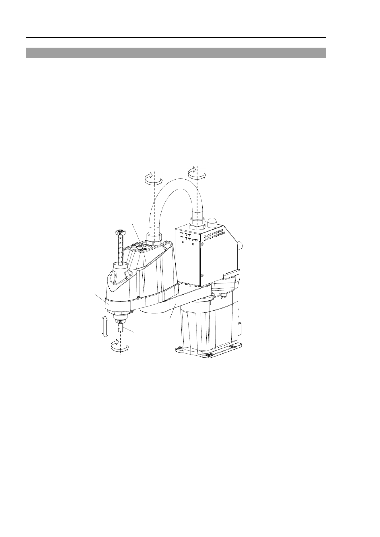
1.6 Emergency Movement Without Drive Power
When the system is placed in emergency mode, push the arm or joint of the Manipulator by
hand as shown below:
Arm #1 Push the arm by hand.
Arm #2 Push the arm by hand.
Joint #3 The joint cannot be moved up/down by hand until the solenoid brake
applied to the joint has been released. Move the joint up/down while
pressing the brake release switch.
Joint #4 Rotate the shaft by hand.
Joint #3
brake release switch
Joint #1
(rotating)
Joint #2
(rotating)
Joint #3
(up and down)
Joint #4
(rotating)
Arm #1
Arm #2
+
−
+
−
+
−
+
−
Shaft
(Illustration: T3-B401S)
The brake release switch affects only Joint #3. When the brake release switch is pressed in
emergency mode, the brake for Joint #3 is released.
Be careful of the shaft while the brake release switch is pressed because the shaft may be
lowered by the weight of an end effector.
When the following errors are occurred, the manipulator brake is not released even if
pressing the brake release switch.
Check the cable connections and remove the error causes. Then, apply the power again
and release the brake.
Errors: 1552, 2118, 4003, 4004, 4009, 4100, 4101, 4103, 4187, 4188, 4189, 4191, 4192,
4233, 4240, 4285-4292, 9633, 9640, 9691, 9685-9692
NOTE
NOTE
T3-B T6-B Manipulator 1. Safety
T-B series Rev.6 35
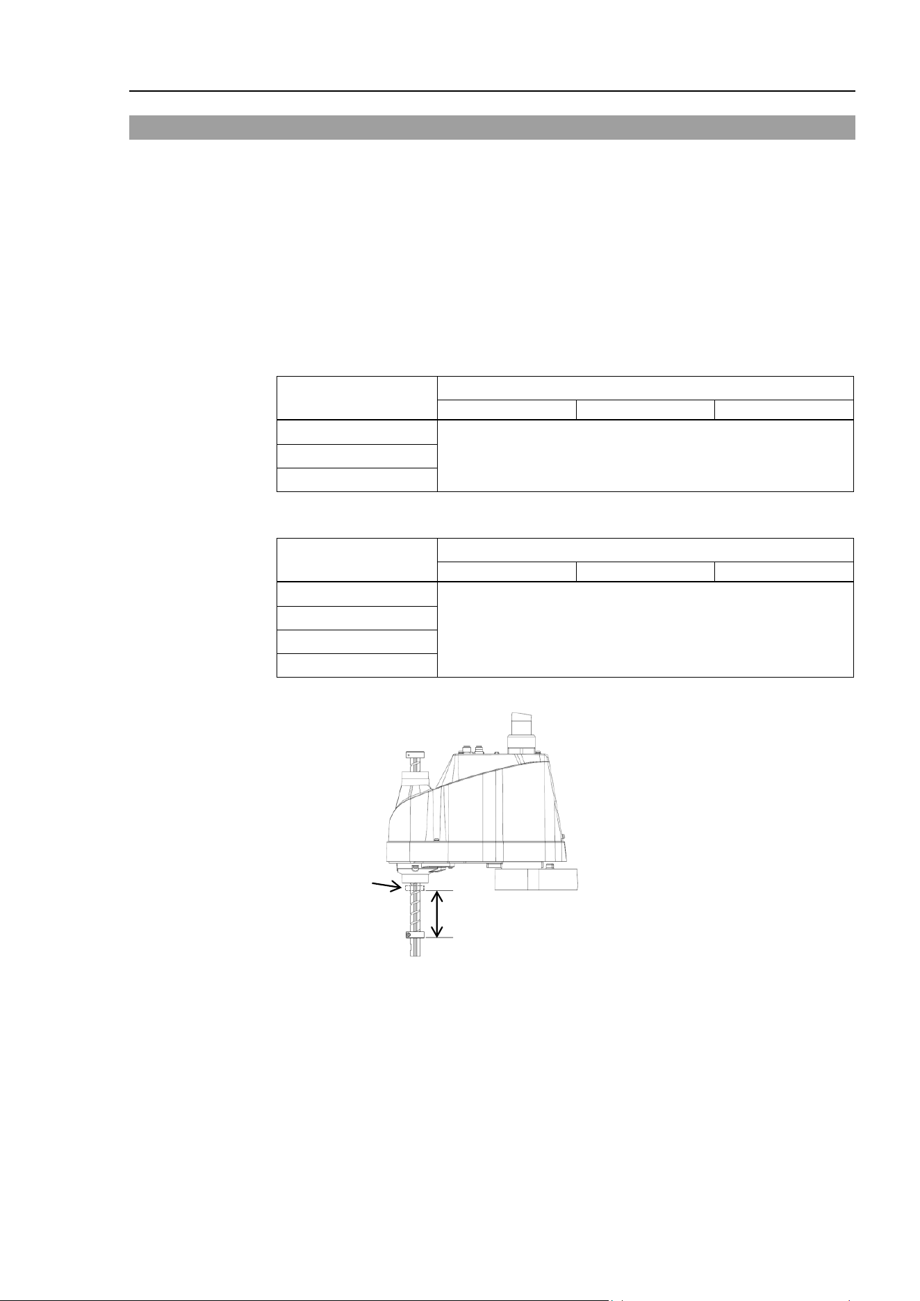
1.7 ACCELS Setting for CP Motions
To make the Manipulator move in CP motion, see the following and set ACCELS properly
according to the tip load and the Z-axis height.
Improper setting may cause following problems.
- Decline in the life and damage of the ball screw spline
Set the ACCELS as follows depending on the Z axis height.
ACCELS setting values by Z-axis height and tip load
T3-B
Z axis height
(mm)
Tip load
1kg or less
2kg or less
3kg or less
__- 0 > Z >= _- 50
10000 or less
_- 50 > Z >= - 100
- 100 > Z >= - 150
T6-B
Z axis height
(mm)
Tip load
1kg or less
2kg or less
3kg or less
__- 0 > Z >= _- 50
10000 or less
_- 50 > Z >= - 100
- 100 > Z >= - 150
- 150 > Z >= - 200
Z
Z-axis height 0
(Origin position)
If the Manipulator is operated in CP motion with the wrong set values, make sure to check
the following points.
- Whether or not the ball screw spline shaft is deformed or bent
NOTE
T3-B T6-B Manipulator 1. Safety
36 T-B series Rev.6
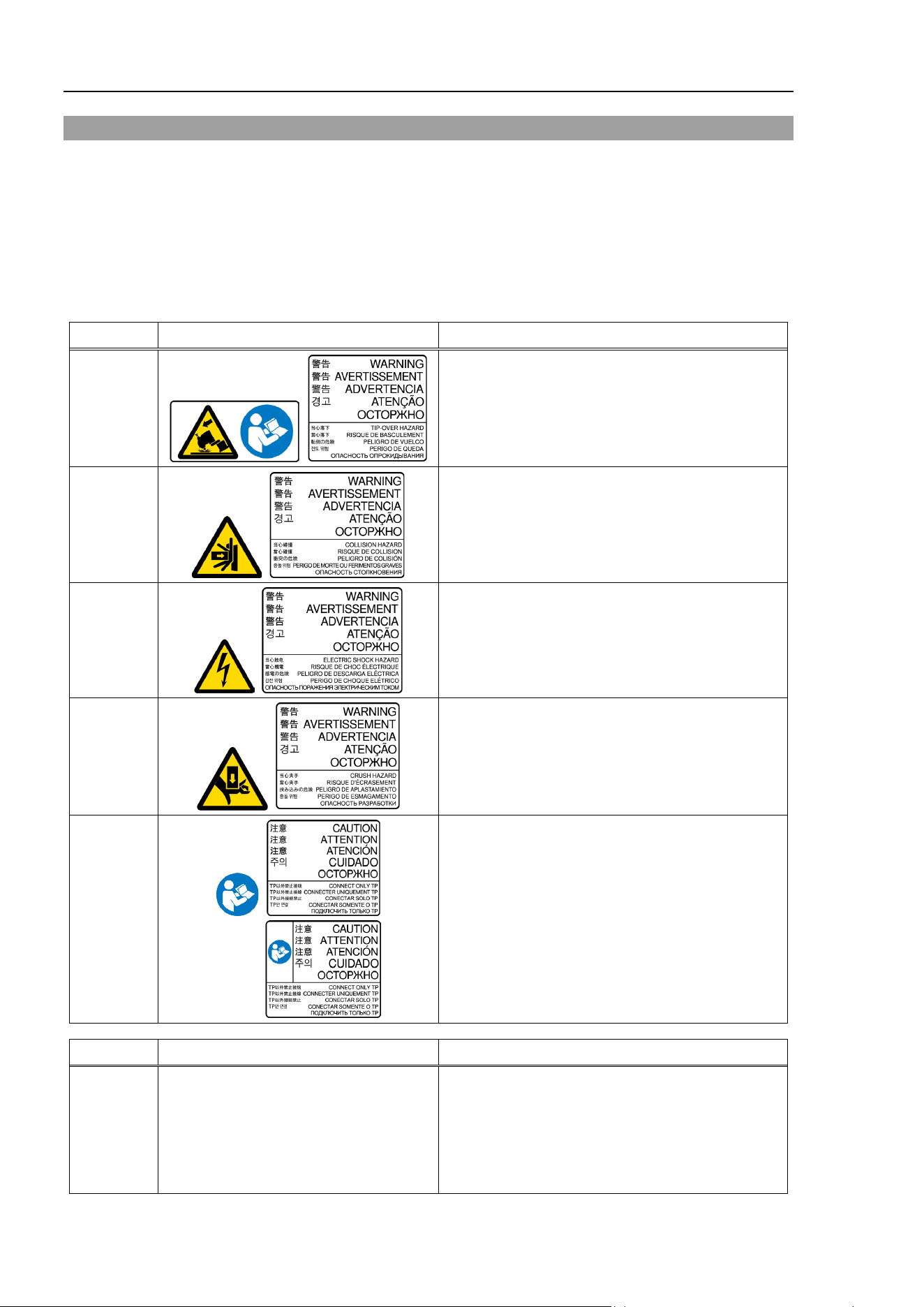
1.8 Labels
The Manipulator has the following warning labels.
The warning labels are attached around the locations where specific dangers exist.
Be sure to comply with descriptions and warnings on the labels to operate and maintain the
Manipulator safely.
Do not tear, damage, or remove the warning labels. Use meticulous care when handling
those parts or units to which the following warning labels are attached as well as the nearby
areas.
Location
Warning Label NOTE
A
Before loosening the base mounting screws, hold
the arm and secure it tightly with a band to prevent
hands or fingers from being caught in the
Manipulator.
B
Do not enter the operation area while the
Manipulator is moving. The robot arm may collide
against the operator. This is extremely hazardous
and may result in serious safety problems.
C
Hazardous voltage exists while the Manipulator is
ON. To avoid electric shock, do not touch any
internal electric parts.
D
You can catch your hand or fingers between the
shaft and cover when bringing your hand close to
moving parts.
H
Do not connect the followings to the TP port of the
Manipulator that attached this label. Connecting to
the followings may result in malfunction of the
device because pin assignments are different.
OPTIONAL DEVICE dummy plug
Operation Pendant OP500
Operation Pendant OP500RC
Jog Pad JP500
Teaching Pendant TP-3**
Operator Panel OP1
Location Label NOTE
1
-
The product name, model name, serial number,
information which laws and regulations are
supported, product specifications, manufacturer,
importer, date of manufacture, country of
manufacture, etc. are listed.
For details, see the label affixed to the product.
T3-B T6-B Manipulator 1. Safety
T-B series Rev.6 37
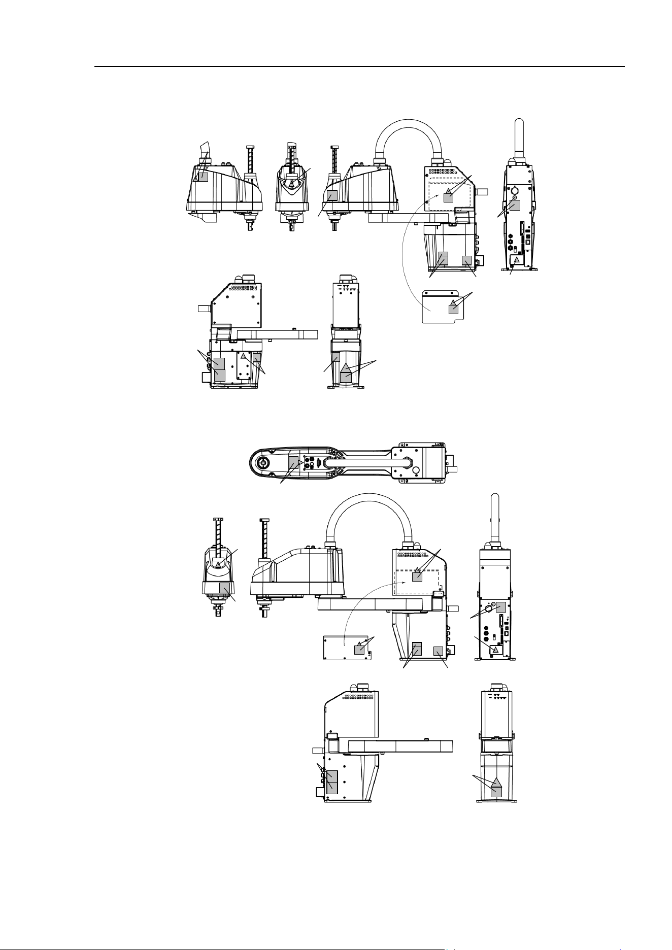
Location of Labels T3-B
B
A
C
1
D
C
C
C
C
D
C
C
H
Location of Labels T6-B
B
A
C
1
D
C
C
D
C
C
H

T3-B T6-B Manipulator 1. Safety
38 T-B series Rev.6
1.9 Response for Emergency or Malfunction
1.9.1 Collision
When the Manipulator collides with a mechanical stopper or peripheral device etc.,
discontinue use and contact the supplier.
1.9.2 Getting body caught in Manipulator
When the operator is caught between the Manipulator and a mechanical part such as a base
table, press the emergency stop switch to release the brake on the subject arm, and then
move the arm by hand.
How to release a brake
For details, refer to “1.6 Emergency Movement Without Drive Power”.
T3-B T6-B Manipulator 2. Specifications
T-B series Rev.6 39
2. Specifications
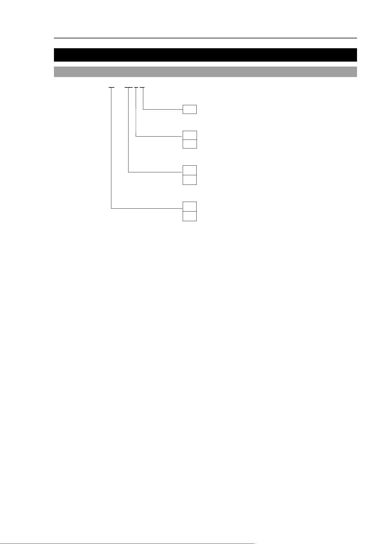
2.1 Model Number
T3 - B 40
1 S
Environment
S
: Standard
Arm length
40
: 400 mm
60
: 600 mm
Payload
3 : 3 kg
6 : 6 kg
For details on the specifications, refer to “Appendix A: T3-B T6-B Specifications”.
Joint #3 stroke
1
: 150 mm
2
: 200 mm
T3-B T6-B Manipulator 2. Specifications
40 T-B series Rev.6
2.2 Part Names
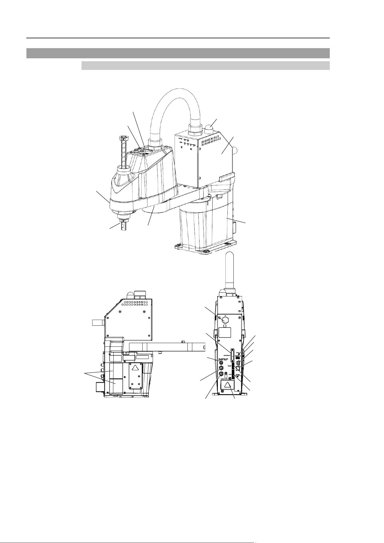
2.2.1 T3-B
Joint #3
Brake Release
S
witch
Arm #1
Arm #2
Base
Shaft
Signature label
(Serial No.
of Manipulator)
Fittings (blue)
for ø4 mm
pneumatic tube
LED Lamp
Fittings (blue)
for ø6 mm
pneumatic tube
TP Connector
EMERGENCY
Connector
Power Supply Cover
(AC power connector inside)
I/O (Input) Connector
I/O (Output) Connector
LAN (Ethernet)
Connector
Port of
PC for development
RESET Switch
Fittings (white)
for ø6 mm
pneumatic tube
Power Unit
MEMORY Port
Hand I/O Connecter
- The brake release switch affects only Joint #3. When the brake release switch is pressed
in emergency mode, the brake for Joint #3 is released.
- While the LED lamp is on, the current is being applied to the manipulator. Performing
any work with the power ON is extremely hazardous and it may result in electric shock
and/or improper function of the robot system. Make sure to turn OFF the Manipulator
power before the maintenance work.
NOTE
T3-B T6-B Manipulator 2. Specifications
T-B series Rev.6 41
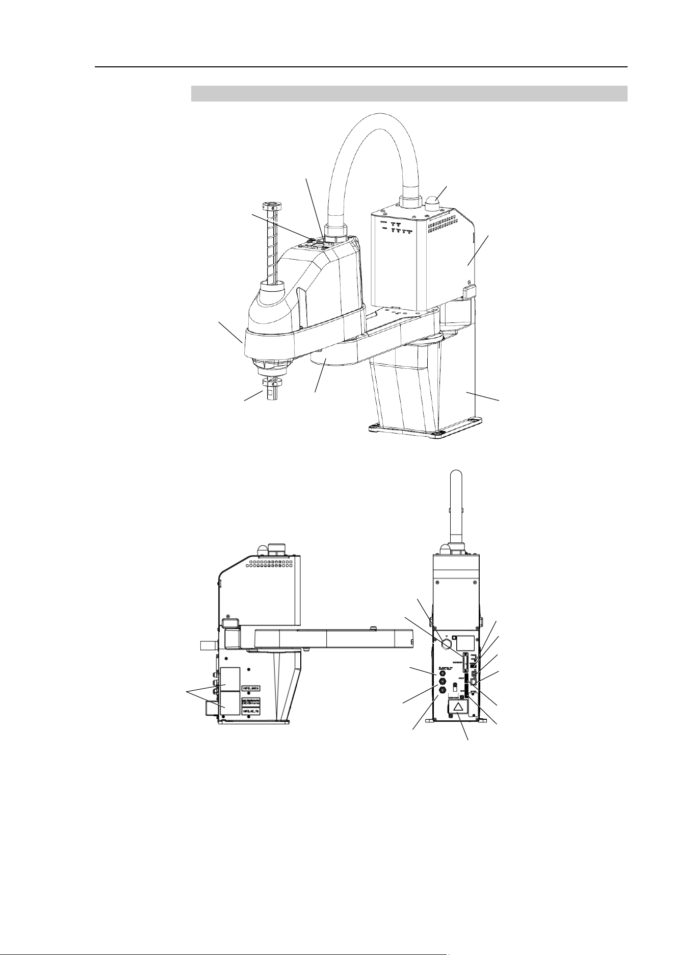
2.2.2 T6-B
Joint #3
Brake Release Switch
Arm #1
Arm #2
Base
Shaft
Signature label
(Serial No.
of Manipulator)
Fittings (blue)
for ø4 mm
pneumatic tube
LED Lamp
Fittings (blue)
for ø6 mm
pneumatic tube
TP Connector
EMERGENCY
Connector
Power Supply Cover
(AC power connector inside)
I/O (Input) Connector
I/O (Output) Connector
LAN (Ethernet)
Connector
Port of PC for development
RESET Switch
Fittings (white)
for ø6 mm
pneumatic tube
Power Unit
MEMORY Port
Hand I/O Connecter
- The brake release switch affects only Joint #3. When the brake release switch is pressed
in emergency mode, the brake for Joint #3 is released.
- While the LED lamp is ON, current is applied to the manipulator. Performing any work
with the power ON is extremely hazardous and it may result in electric shock and/or
improper function of the robot system. Make sure to turn OFF the Manipulator power
before maintenance work.
NOTE
T3-B T6-B Manipulator 2. Specifications
42 T-B series Rev.6
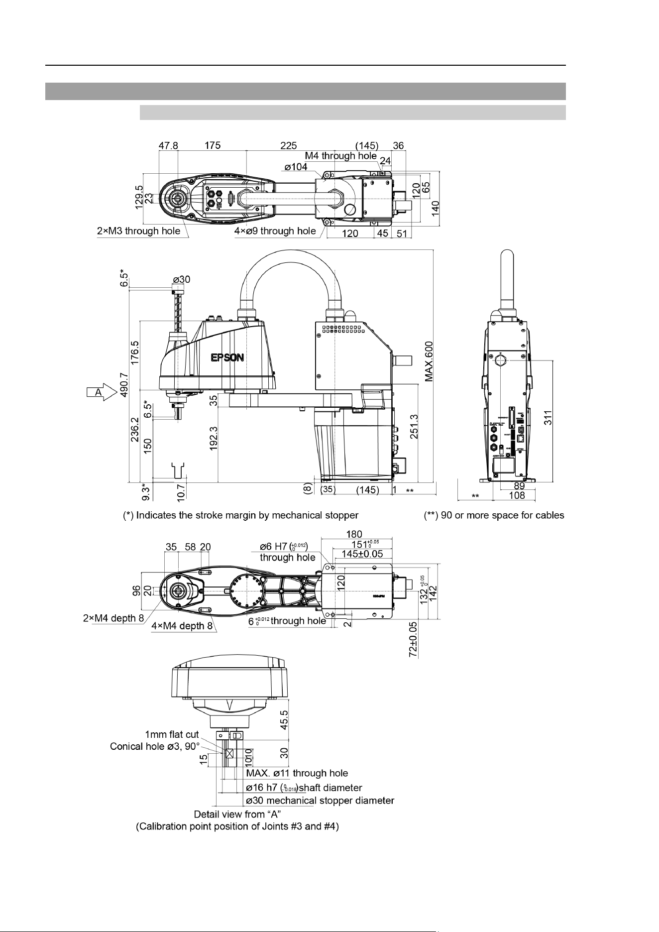
2.3 Outer Dimensions
2.3.1 T3-B
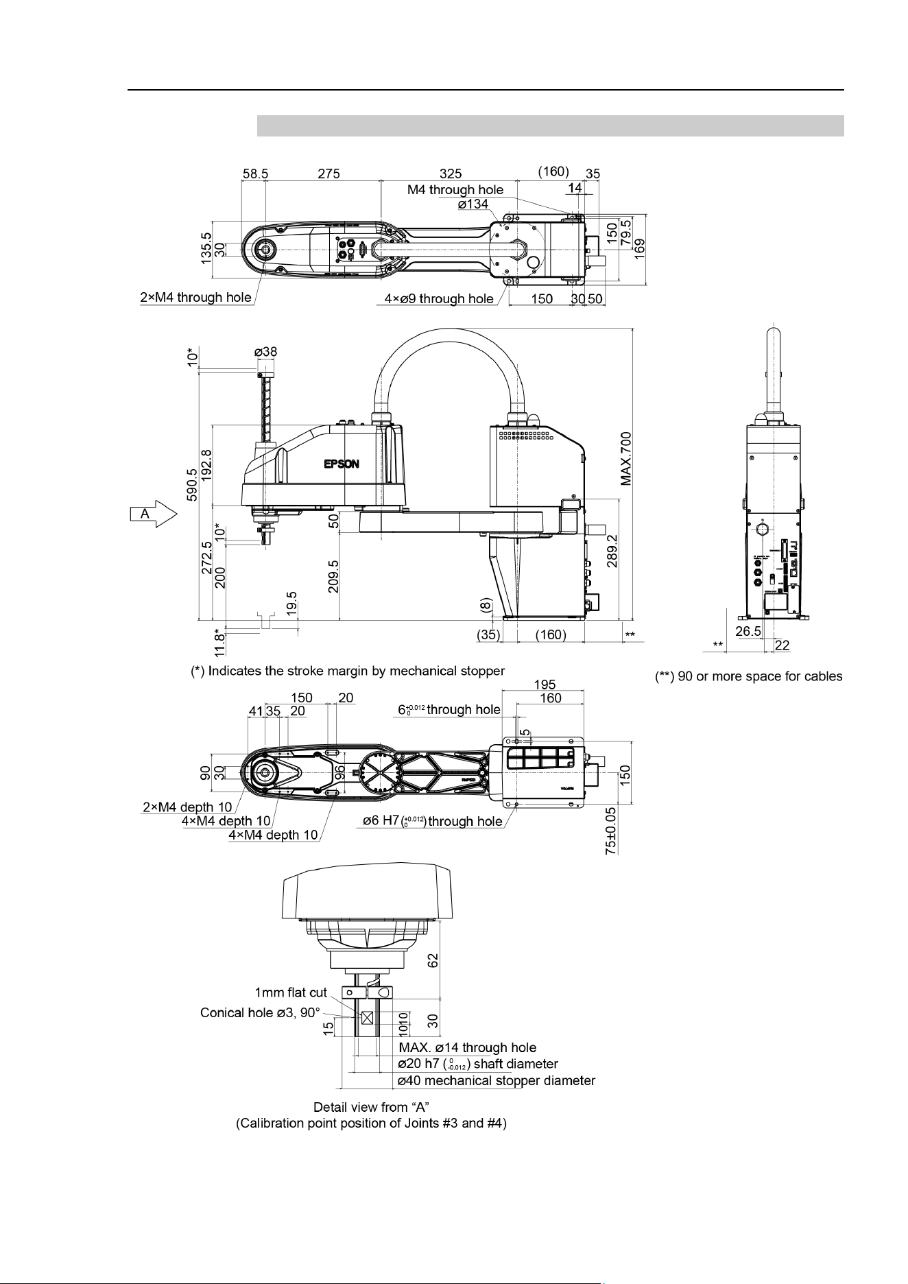
T3-B T6-B Manipulator 2. Specifications
T-B series Rev.6 43
2.3.2 T6-B
T3-B T6-B Manipulator 2. Specifications
44 T-B series Rev.6
2.4 System Example
T3-B / T6-B
Standard
Standard I/O
Remote I/O
Ethernet
Hand I/O
USB (for save)
USB (for development)
ModBus
Fieldbus
Slave
Option
TP2
TP3
*2
*3
Option: Teaching Pendant
Windows *1
EPSON RC+ 7.0
Software
USB 2.0 or
Ethernet
Option
(Illustration: T3-B401S)
*1 For system requirements, refer to the following manual:
EPSON RC+ 7.0 User's Guide
*2 Either teaching pendant is available.
*3 When connecting to T3-B/T6-B, specified convert cable is necessary.
T3-B T6-B Manipulator 2. Specifications
T-B series Rev.6 45
2.5 Specifications
For the specifications of each model, refer to “Appendix A: Specifications”.
2.6 How to Set the Model
The Manipulator model for your system has been set before shipment from the factory. It is
normally not required to change the model when you receive your system.
CAUTION
■
When you need to change the setting of the Manipulator model, be sure to set the
Manipulator model properly.
Improper setting of the Manipulator model may result
in abnormal or no operation of the Manipulator and/or cause safety problems.
If the custom specifications number (MT***) is described on MODEL of the signature label
(S/N label), the Manipulator has custom specifications. The custom specifications may
require a different configuration procedure; check the custom specifications number
(MT***) and contact the supplier of your region when necessary.
The Manipulator model can be set from software.
Refer to the chapter Robot Configuration in the EPSON RC+ User’s Guide.
NOTE

T3-B T6-B Manipulator 3. Environments and Installation
46 T-B series Rev.6
3. Environments and Installation
Unpacking and transportation of the Manipulators and robotic equipment shall be performed
by personnel who has taken robot system training held by us and suppliers and should
conform to all national and local codes.
3.1 Environmental Conditions
A suitable environment is necessary for the robot system to function properly and safely. Be
sure to install the robot system in an environment that meets the following conditions:
Item
Conditions
Ambient temperature*
5 to 40°C
Ambient relative
humidity
20 to 80% (with no condensation)
Fast transient burst
noise
2 kV or less (Power supply wire)
1 kV or less (Signal wire)
Electrostatic noise
4 kV or less
Altitude
1000 m or lower
Environment - Install indoors
- Keep away from direct sunlight
- Keep away from dust, oily smoke, salinity, metal
powder or other contaminants
- Keep away from flammable or corrosive solvents
and gases
- Keep away from water
- Keep away from shock or vibration
- Keep away from sources of electric noise
- Keep away from strong electric or magnetic fields
- Keep away from explosive area
- Keep away from a large quantity of radiation
* When the product is used in a low temperature environment around the minimum
temperature of the product specification, or when the product is suspended for a long time
on holidays or at night, a collision detection error may occur due to the large resistance
of the drive unit immediately after the start of operation. In such a case, it is recommended
to warm up for about 10 minutes.
Manipulators are not suitable for operation in harsh environments such as painting areas,
etc. When using Manipulators in inadequate environments that do not meet the above
conditions, please contact the supplier of your region.
NOTE
T3-B T6-B Manipulator 3. Environments and Installation
T-B series Rev.6 47
Special Environmental Conditions
Surface of the Manipulator has general oil resistance. However, if your requirements specify
that the Manipulator must withstand certain kinds of oil, please contact the supplier of your
region.
Rapid change in temperature and humidity can cause condensation inside the Manipulator.
If your requirements specify that the Manipulator handles food, please contact the supplier
of your region to check whether the Manipulator will damage the food or not.
The Manipulator cannot be used in corrosive environments where acid or alkaline is used.
In a salty environment where the rust is likely to gather, the Manipulator is susceptible to
rust.
WARNING
■
Use an earth leakage breaker on the AC power cable of the
Manipulator to avoid
electric shock and circuit breakdown caused by
short circuit.
CAUTION
■
When cleaning the Manipulator, do not rub it strongly with alcohol or
benzene.
It may lose luster on the coated face.
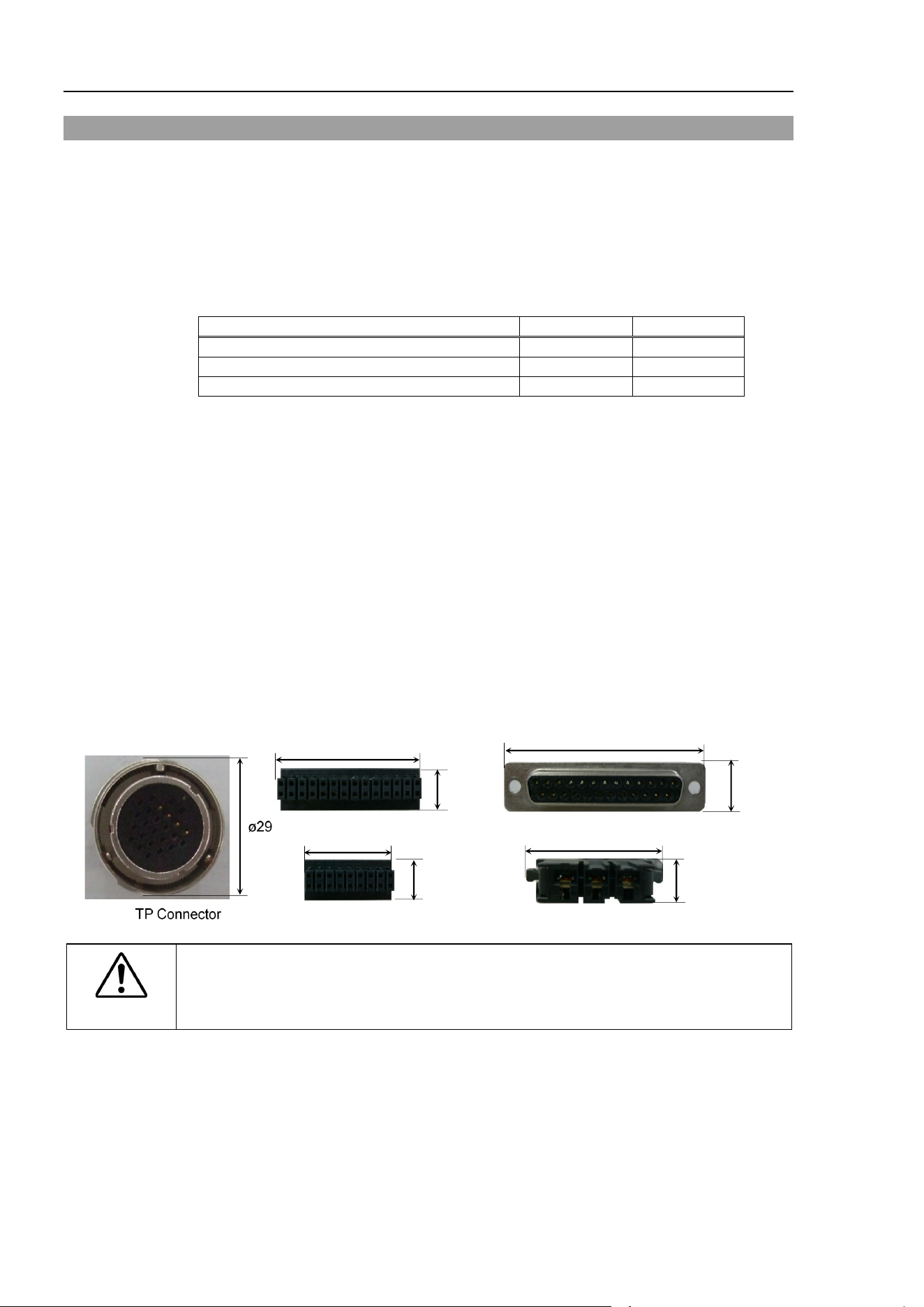
T3-B T6-B Manipulator 3. Environments and Installation
48 T-B series Rev.6
3.2 Base Table
A base table for anchoring the Manipulator is not supplied. Please make or obtain the base
table for your Manipulator. The shape and size of the base table differs depending on the use
of the robot system. For your reference, we list some Manipulator table requirements here.
Base table is necessary for support not only the weight of the manipulator but also dynamic
motion when operating at the maximum acceleration/deceleration. Provides enough beams
to give sufficient strength.
The torque and reaction force produced by the movement of the Manipulator are as follows:
T3-B
T6-B
Max. Reaction torque on the horizontal plate
150
N·m
350
N·m
Max. Horizontal reaction force
500
N
750
N
Max. Vertical reaction force
900
N
1500
N
The threaded holes required for mounting the Manipulator base are M8. Use mounting bolts
with specifications conforming to ISO898-1 property class: 10.9 or 12.9.
For dimensions, refer to “3.3 Mounting Dimensions”.
The plate for the Manipulator mounting face should be 20 mm thick or more and made of
steel to reduce vibration. The surface roughness of the steel plate should be 25 μm or less.
The table must be secured on the floor or wall to prevent it from moving.
The Manipulator installation surface should have a flatness of 0.5 mm or less and an
inclination of 0.5° or less. If the flatness of the installation surface is improper, the base may
be damaged or the robot may not fully show its performance.
When using a leveler to adjust the height of the base table, use a screw with M16 diameter
or more.
If you are passing cables through the holes on the base table, see the figures below.
I/O (Input) Connector
11
54
37
13
(Unit: mm)
11
24
I/O(Output) Connector
EMERGENCY Connector
9
34
AC Power Connector
WARNING
■
To ensure safety, a safeguard must be installed
for the robot system. For details
on the safeguard, refer to the
1.5 Safeguard.
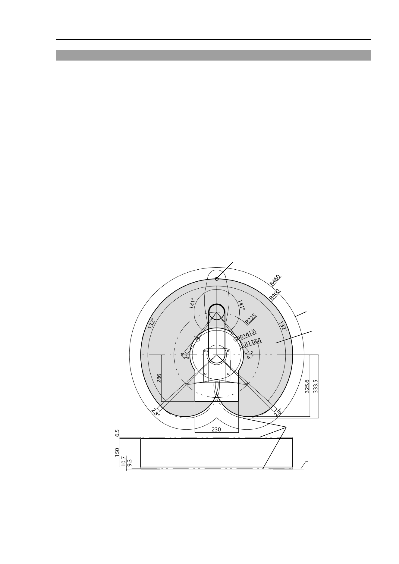
T3-B T6-B Manipulator 3. Environments and Installation
T-B series Rev.6 49
3.3 Mounting Dimensions
The maximum space described in figures shows that the radius of the end effector is 60 mm
or less. If the radius of the end effector exceeds 60 mm, define the radius as the distance to
the outer edge of maximum space.
If a camera or solenoid valve extends outside of the arm, set the maximum range including
the space that they may reach.
Be sure to allow for the following extra spaces in addition to the space required for mounting
the Manipulator and peripheral equipment.
Space for teaching
Space for maintenance and inspection
(Ensure a space to open the covers and plates for maintenance.)
Space for cables
The minimum bend radius of the power cable is 90 mm. When installing the cable, be sure
to maintain sufficient distance from obstacles. In addition, leave enough space for other
cables so that they are not bent forcibly.
Ensure distance to the safeguard from the maximum motion range is more than 100 mm.
T3-B
Center of Joint #3
Maximum space
Motion range
Area limited by mechanical stop
Base mounting face
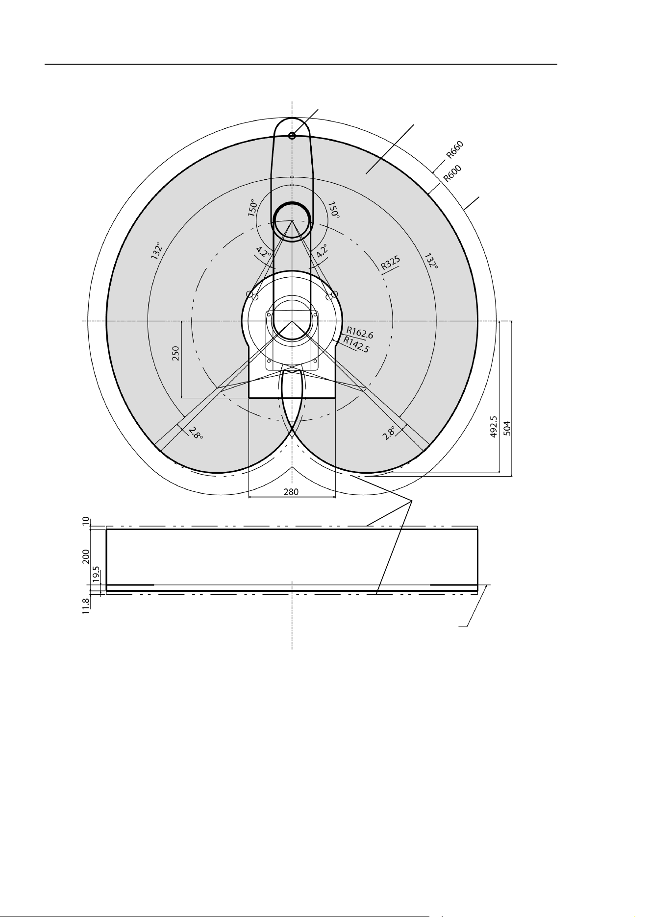
T3-B T6-B Manipulator 3. Environments and Installation
50 T-B series Rev.6
T6-B
Center of Joint #3
Maximum space
Motion range
Area limited
by mechanical stop
Base mounting face
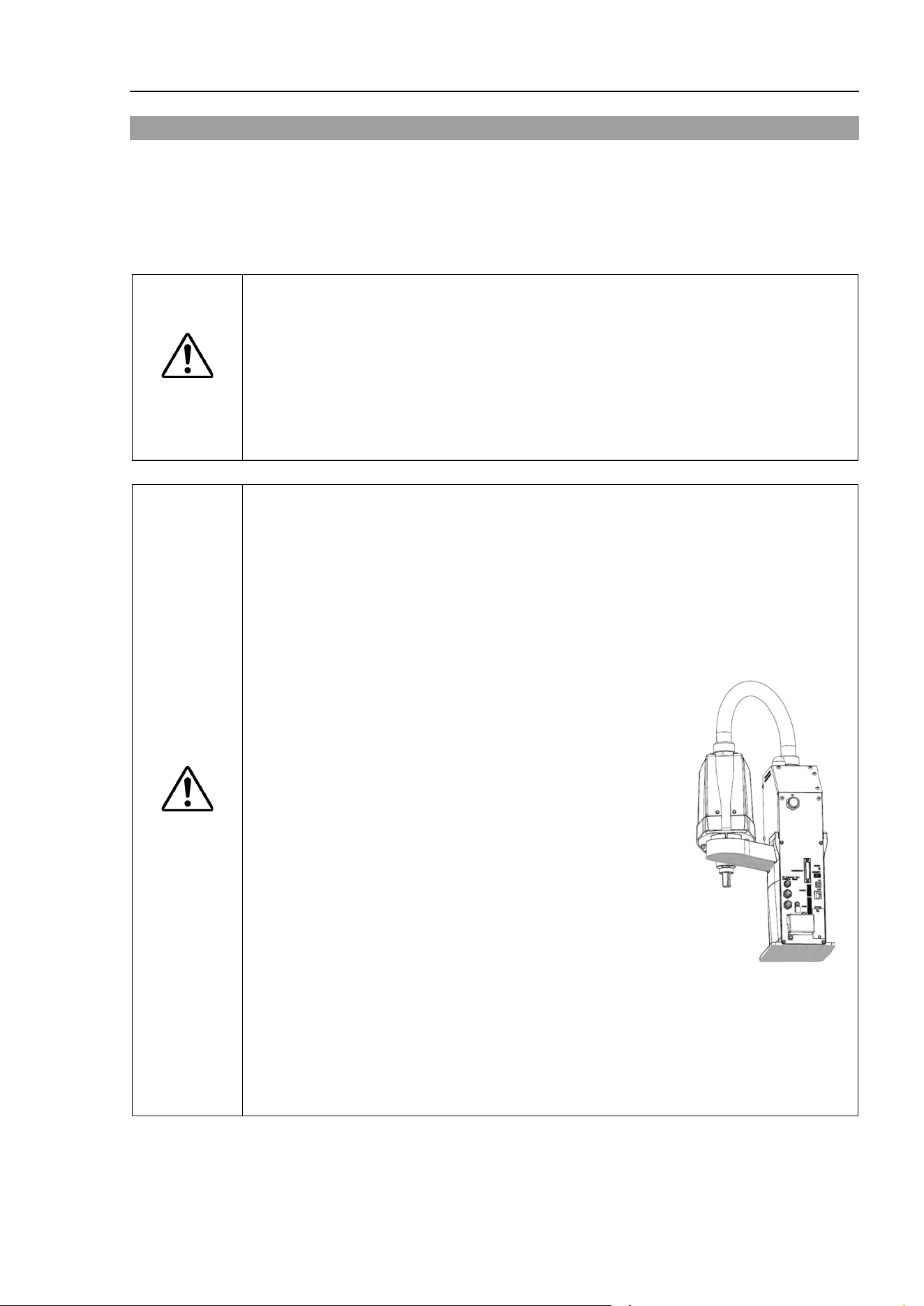
T3-B T6-B Manipulator 3. Environments and Installation
T-B series Rev.6 51
3.4 Unpacking and Transportation
Using a cart or similar equipment, transport the Manipulator in the same conditions as it was
delivered. Observe the following when unpacking the Manipulator.
Unpacking, transportation, and relocation shall be performed by personnel who has taken
robot system training held by us and suppliers and should conform to all national and local
codes.
WARNING
■
Only authorized personnel
should perform sling work and operate a crane and a
forklift. When
these operations are performed by unauthorized personnel, it is
extremely
hazardous and may result in serious bodily injury and/or severe
equipment damage to the robot system.
■
Stabilize the Manipulator with your hands when hoisting it. Unstable hoisting is
extremely hazardous and may result in serious bodily injury
and/or severe
equipment damage to the robot system as the fall of the Manipulator.
CAUTION
■
Using a cart or similar equipment, transport the Manipulator in the same manner
as it was delivered.
■
When removing the anchor bolts, support the
Manipulator to prevent falling.
Removing the anchor bolts without supporting the Manipulator may get hands,
fingers, or feet caught as the Manipulator may fall.
■
The arm is
secured with a sheet. Leave the sheet secured until you finish the
installation so as not to get hands or fingers caught
.
■
To carry the Manipulator, have two or more people to
work on it and secure the Manipulator to the delivery
equipment or hold the bottom of Arm #1 and
or bottom of
the base areas (indicated in gray
in the figure) by hand.
When holding the bottom of the base by hand, be very
careful not to get your hands or fingers caught.
T3-B401S: approx.14kg: 31lbs.
T6-B602S: approx.21kg: 46lbs.
(Illustration: T3-B401S)
■
Make sure not to hold the
power unit when carrying the manipulator.
■
When transporting the Manipulator for a long distance, secure it to the delivery
equipment directly so that the Manipulator never falls.
If necessary, pack the Manipulator in the same style as
it was delivered.
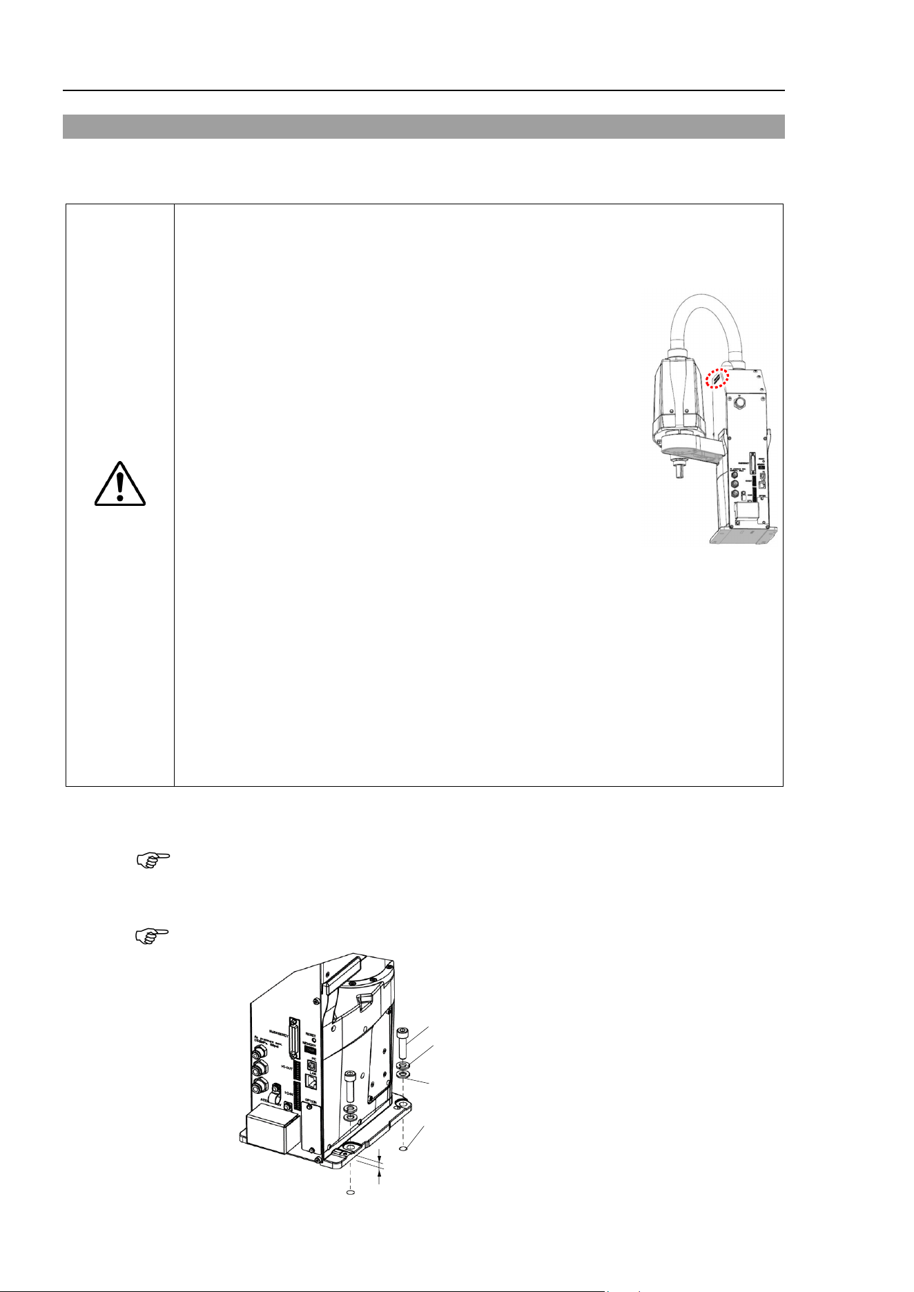
T3-B T6-B Manipulator 3. Environments and Installation
52 T-B series Rev.6
3.5 Installation Procedure
The installation shall be made by personnel who has taken robot system training held by us
and suppliers and should conform to all national and local codes.
CAUTION
■
The
Manipulator must be installed to avoid interference with buildings, structures,
utilities, other
machines and equipment that may create a trapping hazard or pinch
points.
■
Install
the Manipulator in order to secure ventilation around
the air supply/exhaust port.
■
Oscillation (resonance) may
occur during operation depending on rigidity of the
installation table.
If the oscillation occurs, improve rigidity of the table or change the speed or
acceleration
and deceleration settings.
■
Install the
Tab le Top Mounting Manipulator with two or more people.
The Manipulator weigh
ts are as follows. Be careful not to get hands, fingers, or
feet caught and/or have equipment damage
d by a fall of the Manipulator.
T3-B401S: approx.14kg: 31lbs.
T6-B602S: approx.21kg: 46lbs.
Secure the base to the base table with four bo
lts.
Use bolts
with specifications conforming to ISO898-1 Property Class: 10.9 or 12.9.
Tightening torque: 32.0±1.6 N·m
Make sure to remove
the protective tape and the wire tie for mechanical stop protector.
10 mm
Screw Hole
(depth 20 mm
or more)
4-M8×30
Spring
Washer
Plane Washer
(Illustration: T3-B401S)
NOTE
NOTE
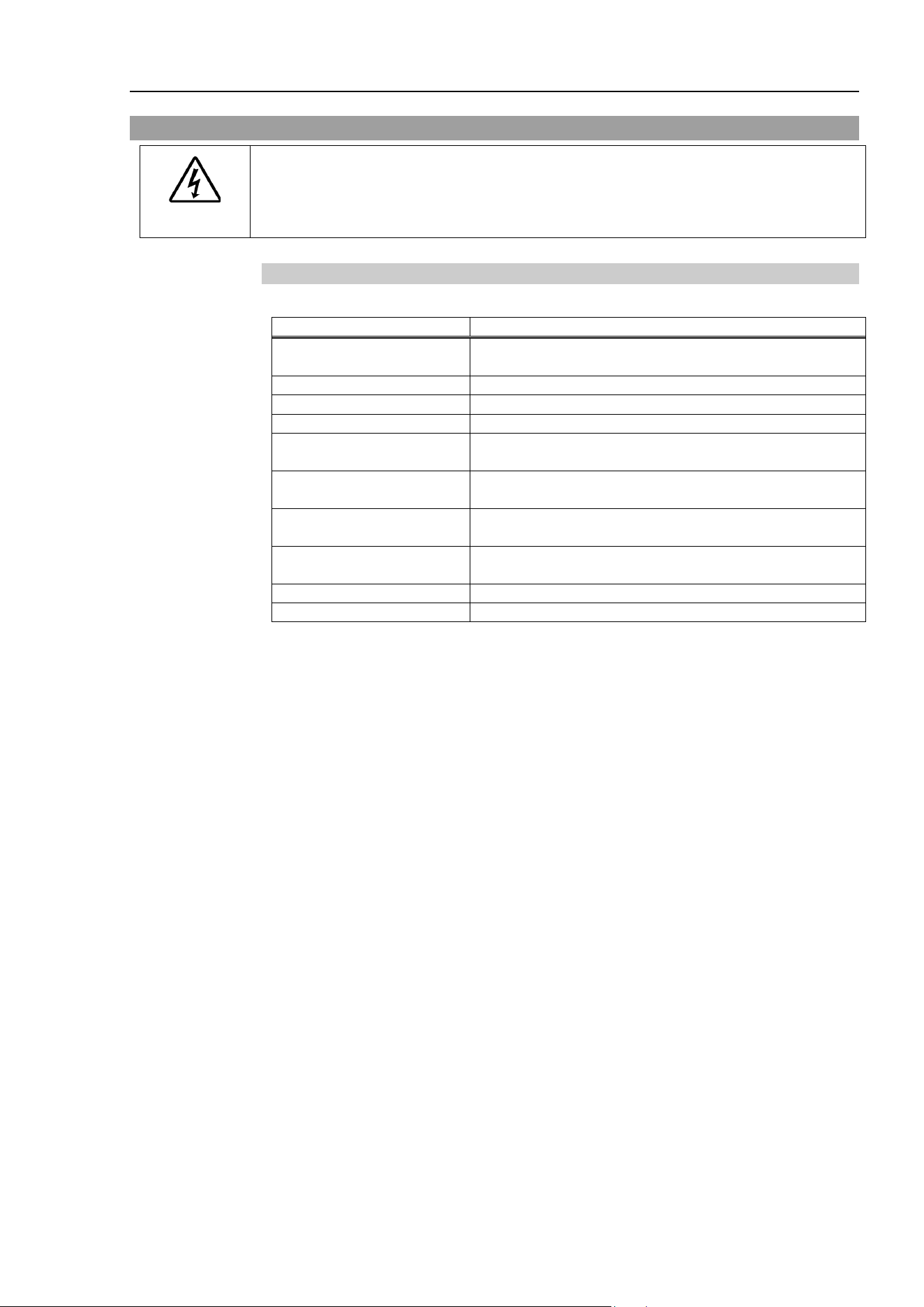
T3-B T6-B Manipulator 3. Environments and Installation
T-B series Rev.6 53
3.6 Power Supply
WARNING
■
There is no power switch on the Manipulator. Right after inserting power plug to
power, the Robot System turns ON.
Be careful about electric shock when inserting power plug.
3.6.1 Specifications
Ensure that the available power meets following specifications.
Item
Specification
Voltage
100 to 240 VAC
(Input voltage should be with in ±10 % of the rated voltage.)
Phase
Single phase
Frequency
50/60 Hz
Momentary Power Interrupt
Less than 10 msec.
Rated Capacity
T3-B: 660 VA
T6-B: 1,200VA
Short-circuit
Current Rating
5kA
Maximum Load Current
T3-B: 3.3A
T6-B: 6.0A
Inrush Current
(When AC power is turned ON)
T3-B: Max. 30A (2 ms or less)
T6-B: Max. 60A (2 ms or less)
Leakage Current
Max. 10 mA
Ground Resistance
TN ground (100 Ω or less)
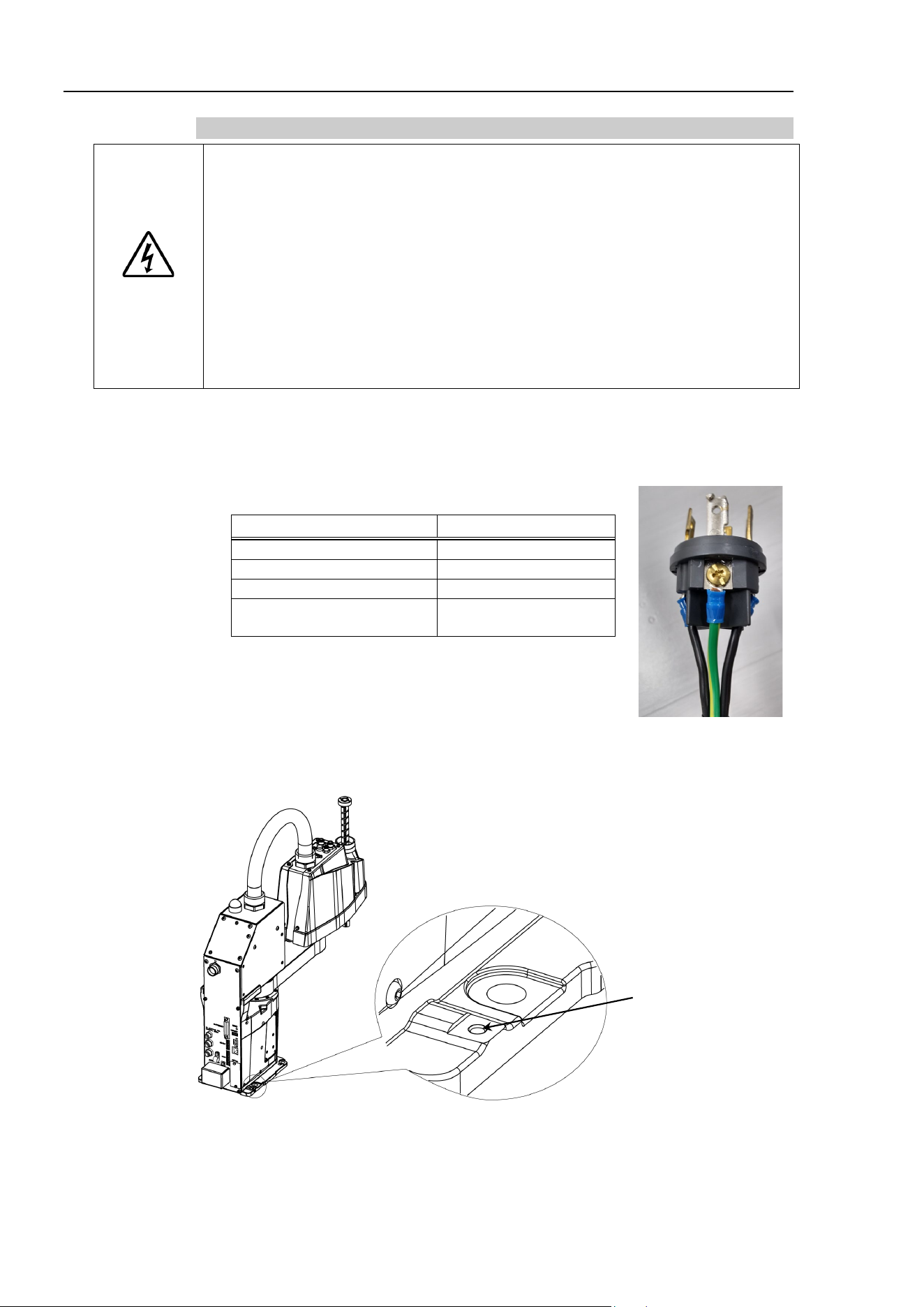
T3-B T6-B Manipulator 3. Environments and Installation
54 T-B series Rev.6
3.6.2 AC Power Cable
WARNING
■ Make sure that the operations are done by a qualified personal.
■ Be sure to connect the earth wire (green/yellow) of the AC power cable to the
earth terminal of the factory power supply.
Also, ground directly via a hole on the base to ground the manipulator
completely.
The equipment must be grounded properly at all times to avoid the risk of
electric shock.
■ Always use a plug or a disconnecting device for power connecting cable.
Never connect the Manipulator directly to the factory power supply.
■ Select a plug or a disconnecting device which conforms to safety standards of
each country.
When connecting the connecter of AC cable to the Manipulator, make sure to insert
completely until you hear a “click”.
The specification for the power supply connection side is the table below.
Item
Specification
AC power wire (2 cables)
Black
Ground wire
Green/Yellow
Cable length
5 m
Terminal
M4 round solderless
terminal
When you attach to a plug, refer to the picture on the
right.
Directly connect the ground line to the Manipulator using bolt hole in the figure below.
It is recommended that the core size of the grounding wire be 5.5 mm
2
or more.
Bolt hole
(for grounding)
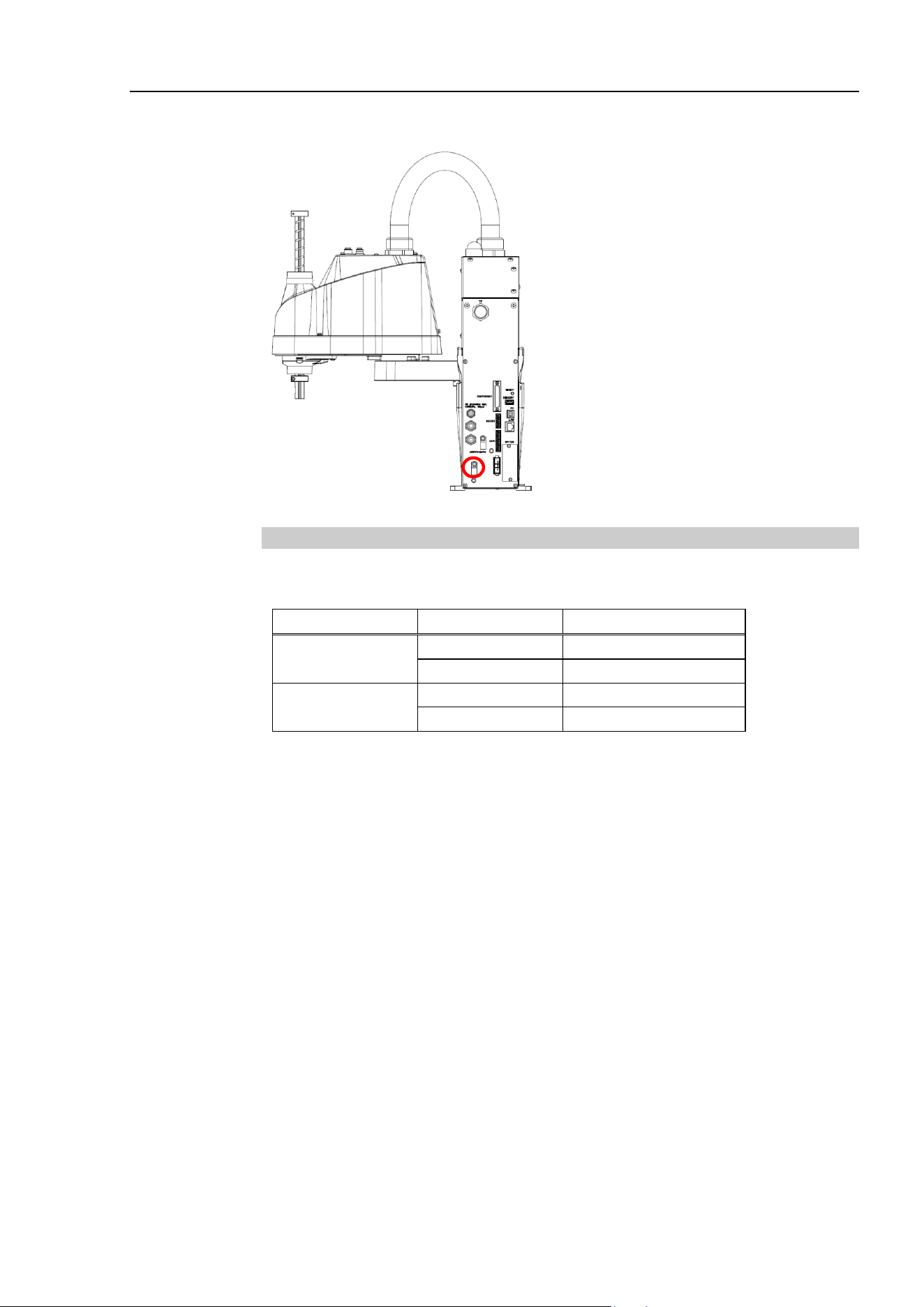
T3-B T6-B Manipulator 3. Environments and Installation
T-B series Rev.6 55
Use cable clamp on rear side of the Manipulator to fix AC power cable.
AC Power Cable Clamp
(Illustration: T3-B401S)
3.6.3 Breaker
Install an earth leakage circuit breaker or a circuit breaker in the AC power cable line.
For the rated electric current of the circuit breaker, refer to the following set values.
Manipulator
Power
Rated electric current
T3-B
100VAC
10A
200VAC
5A
T6-B
100VAC
20A
200VAC
10A
If you install a circuit breaker, please select one that can handle the “inrush current”
described in the following section.
Reference: 3.6.1 Specifications
The power receptacle shall be installed near the equipment and shall be easily accessible.
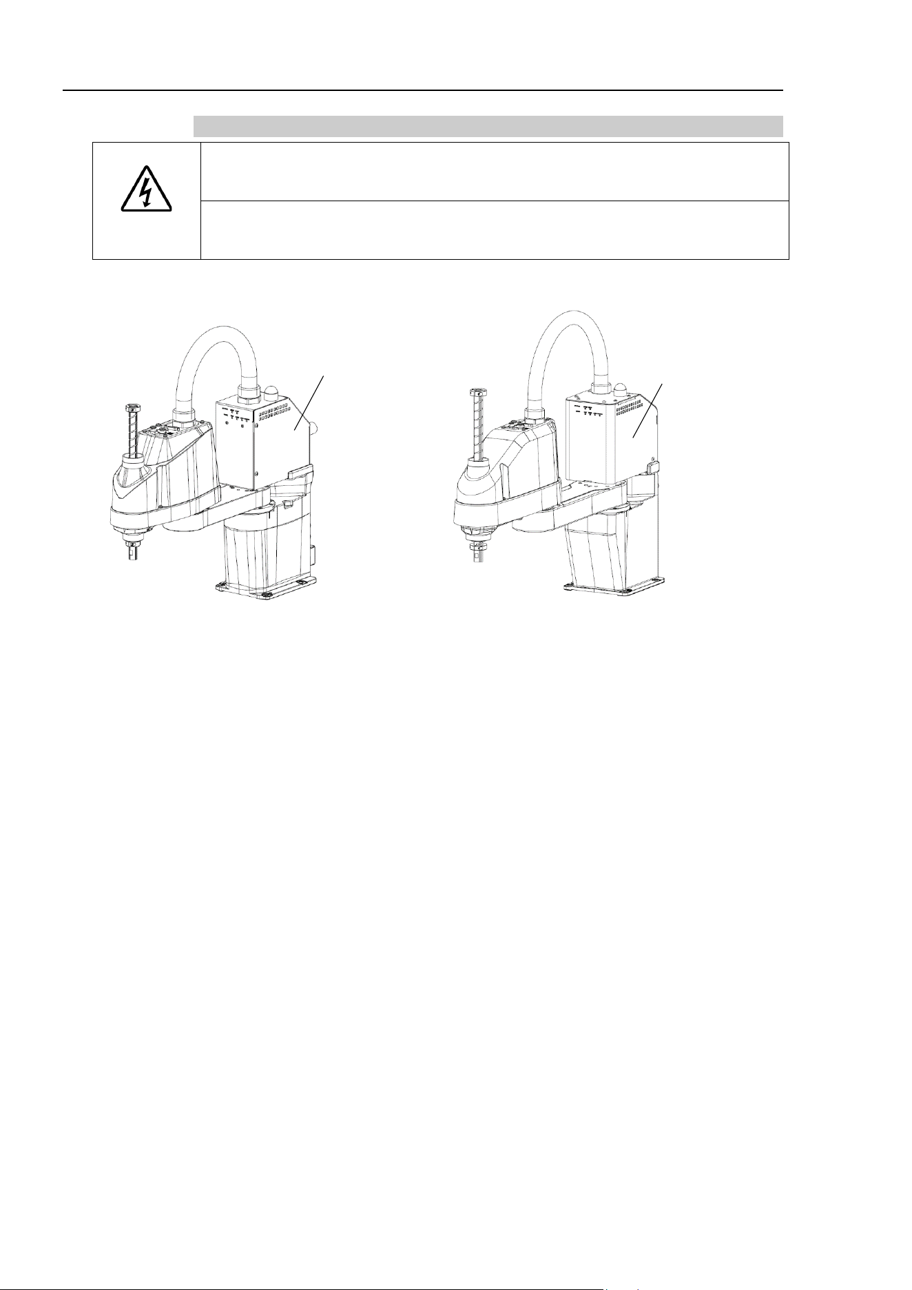
T3-B T6-B Manipulator 3. Environments and Installation
56 T-B series Rev.6
3.6.4 Power Unit
WARNING
■
Do not apply a load by applying weight to power unit. Doing so may result in
deformation or damage of parts.
■
NEVER connect deformed or damaged power unit to the Robot system or
related equipment. It may result in the fire or electric shock.
T3-B
T6-B
Power unit
Power unit
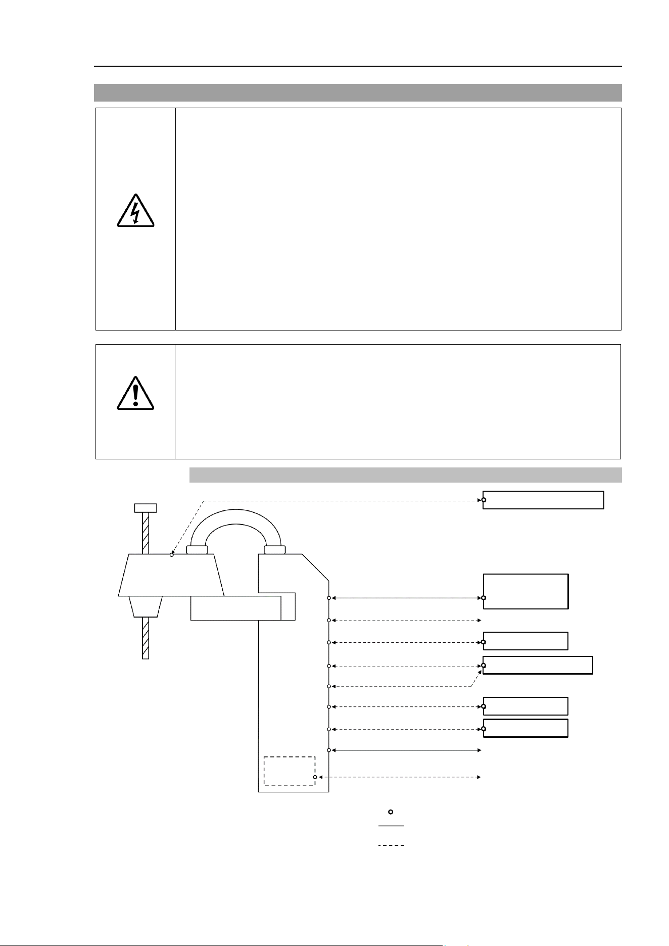
T3-B T6-B Manipulator 3. Environments and Installation
T-B series Rev.6 57
3.7 Connecting the Cables
WARNING
■
To shut off power to the robot system, disconnect the power plug from the power
source. Be sure to connect the AC power cable to a power receptacle.
DO NOT connect it directly to a factory power source.
■
Be sure to connect the cables
properly. Use a tough cable cover to protect the
cables.
Do not allow unnecessary strain on the cables. (Do not put heavy objects
on the cables. Do not bend or
pull the cables forcibly.) The unnecessary strain on
the cables may
result in damage to the cables, disconnection, and/or contact
failure.
Damaged cables, disconnection, or contact failure is extremely hazardous and
may result in electric shock and/or improper function of the robot system.
■
Grounding the manipulator is done by connecting with
Power cable. Ensure that
the
Power cable and ground wire are correctly connected. If the ground wire is
improperly connected to ground, it may result in the fire or electric shock.
CAUTION
■
Make sure that the serial numbers on each equipment match. Improper
connection may not only cause improper function of the robot system but also
serious safety problems.
■
Before connecting the connector, make sure that the pins are not bent.
Connecting with the pins bent may damage the connector and result in
malfunction of the robot system.
3.7.1 Connection Example
Input/ Output device
Accessible connector
Included cable when shipping
Not supplied cable (Prepare by yourself)
100-240VAC
Fieldbus I/O
Output device
PC for development
(1) Hand I/O connector
USB memory
Emergency stop, safety door
Manipulator
Teach
Pendant
Input device
Option
(2) TP connector
(3) EMERGENCY connector
(4) Memory port
(5) PC port for development
(6) LAN (Ethernet)
(7) I/O (Input) connector
(8) I/O (Output) connector
(9) AC power connector
(10) Fieldbus I/O connector

T3-B T6-B Manipulator 3. Environments and Installation
58 T-B series Rev.6
(1) Hand I/O connector
Connect input/output devices of the users.
When there are input/output devices, use this connector.
Be careful about allowable current when using hand I/O connector.
For details, refer to “13. Hand I/O connector”.
(2) TP connector
Connect the option Teach Pendant.
For details, refer to “10.TP Port”.
(3) EMERGENCY
The EMERGENCY connector has inputs to connect the Emergency Stop switch and
the Safety Door switch. For safety reasons, connect proper switches for these input
devices.
For details, refer to
“11. EMERGENCY”.
(4) Memory port
Connect to USB memory.
For details, refer to “8. Memory port”.
(5) PC for develop
ment
Connect the PC for development.
For details, refer to
“7. Development PC Connection Port”.
(6) LAN (EtherNet Communication)
Connect the EtherNet cable.
For details, refer to “9. LAN (Ethernet Communication) Port”.
(7) I/O (Input) connector
This input connector is for output device of the user.
When there is output device, use this connector.
For details, refer to “12. Standard I/O connector”.
(8) I/O (Output) connector
This output connector is for input device of the user.
When there is input device, use this connector.
For details, refer to “12. Standard I/O connector”.
(9) AC power connector
Connector for AC power supply to the manipulator.
(10) Fieldbus I/O connector
If necessary, take EMC countermeasures for the Fieldbus I/O cable.
For details, refer to 3.7.2 Noise Countermeasures.
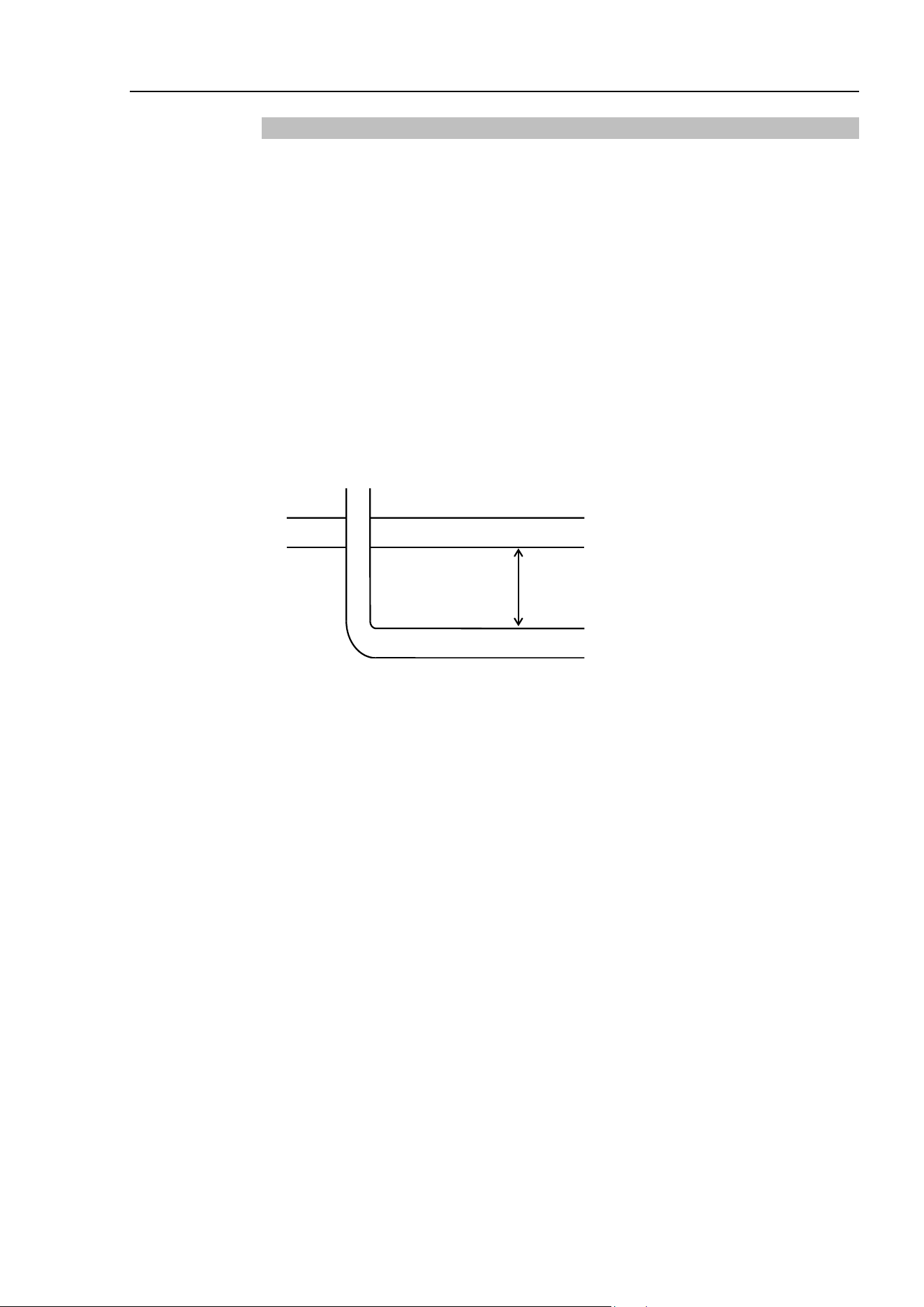
T3-B T6-B Manipulator 3. Environments and Installation
T-B series Rev.6 59
3.7.2 Noise Countermeasures
To minimize electrical noise conditions, the following items must be observed in the
system’s cable wiring:
- The earth wire of the power supply should be grounded. (Ground resistance: 100 Ω or
less) It is important to ground the frame of Manipulator not only for prevention from
electric shock, but also for reducing the influence of electric noise around the
Manipulator. Therefore, be sure to connect the earth wire (yellow/green) of the
Manipulator’s power cable to the ground terminal of the factory power supply. For details
about the plug and AC power cable, refer to
“3.6 Power Supply”.
- Do not tap power from a power line that connects to any equipment which may cause
noise.
- Do not run AC power lines and DC power lines in the same wiring duct, and separate
them as far as possible. For example, separate the AC motor power line and the
Manipulator power line as far as possible from the sensor or valve I/O lines; and do not
bundle both sets of wiring with the same cable tie. If more than one duct/cable must cross
each other, they should cross perpendicularly. The preferable example is shown in the
right figure.
AC Line duct
D
C line duct
As far as possible
- Wire as short as possible to the I/O connector and EMERGENCY connector. Use a
shielded cable and clamp the shield to the attached connector interior. Make sure to keep
away from the peripheral noise source as far as possible.
- Make sure that the induction elements used to connect to the Manipulator’s I/O (such as
relays and solenoid valves) are noise suppression parts. If an induction element without
protection against noise is used, make sure to connect a noise suppression part such as a
diode located at the induction element in parallel with it. In selecting noise suppression
parts, make sure that they can handle the voltage and current incurred by the induction
load.
- As they are easily influenced by noise, keep cable such as USB, Ethernet, or fieldbus
away from peripheral noise sources.
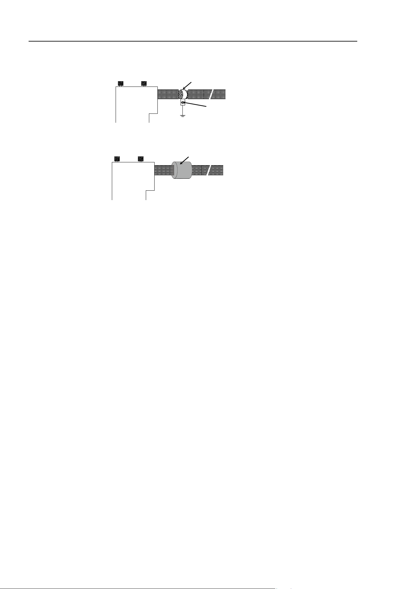
T3-B T6-B Manipulator 3. Environments and Installation
60 T-B series Rev.6
- Perform following EMC countermeasure for the Fieldbus I/O cable as necessary.
- Put together the cable shield side.
Remove the outer cover and fix
with the FG clamp.
Secure the clamps to the
Controller with screws to
ground the shield.
- Mount Ferrite core to the cable.
Ferrite core
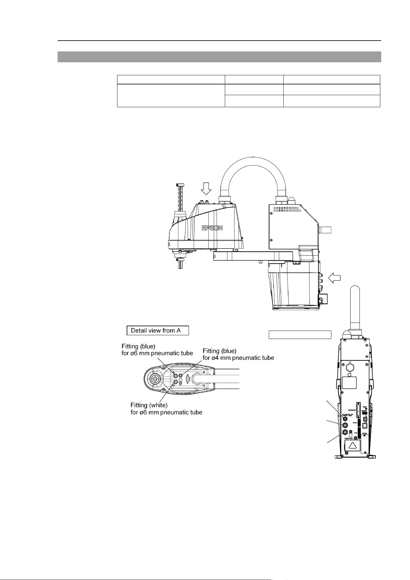
T3-B T6-B Manipulator 3. Environments and Installation
T-B series Rev.6 61
3.8 Pneumatic Tubes
Pneumatic tubes are contained in the cable unit.
Max. Usable Pneumatic Pressure
Pneumatic Tubes
Outer Diameter × Inner Diameter
0.59 MPa (6 kgf/cm
2
: 86 psi)
2
ø 6 mm × ø 4 mm
1
ø 4 mm
×
ø 2.5 mm
Fittings for ø6 mm and ø4 mm (outer diameter) pneumatic tubes are supplied on both ends
of the pneumatic tubes.
T3-B
Fitting (blue)
for ø4
mm pneumatic tube
A
Fitting (white)
for ø6 mm pneumatic tube
B
Detail view from B
Fitting (blue)
for ø6 mm pneumatic tube
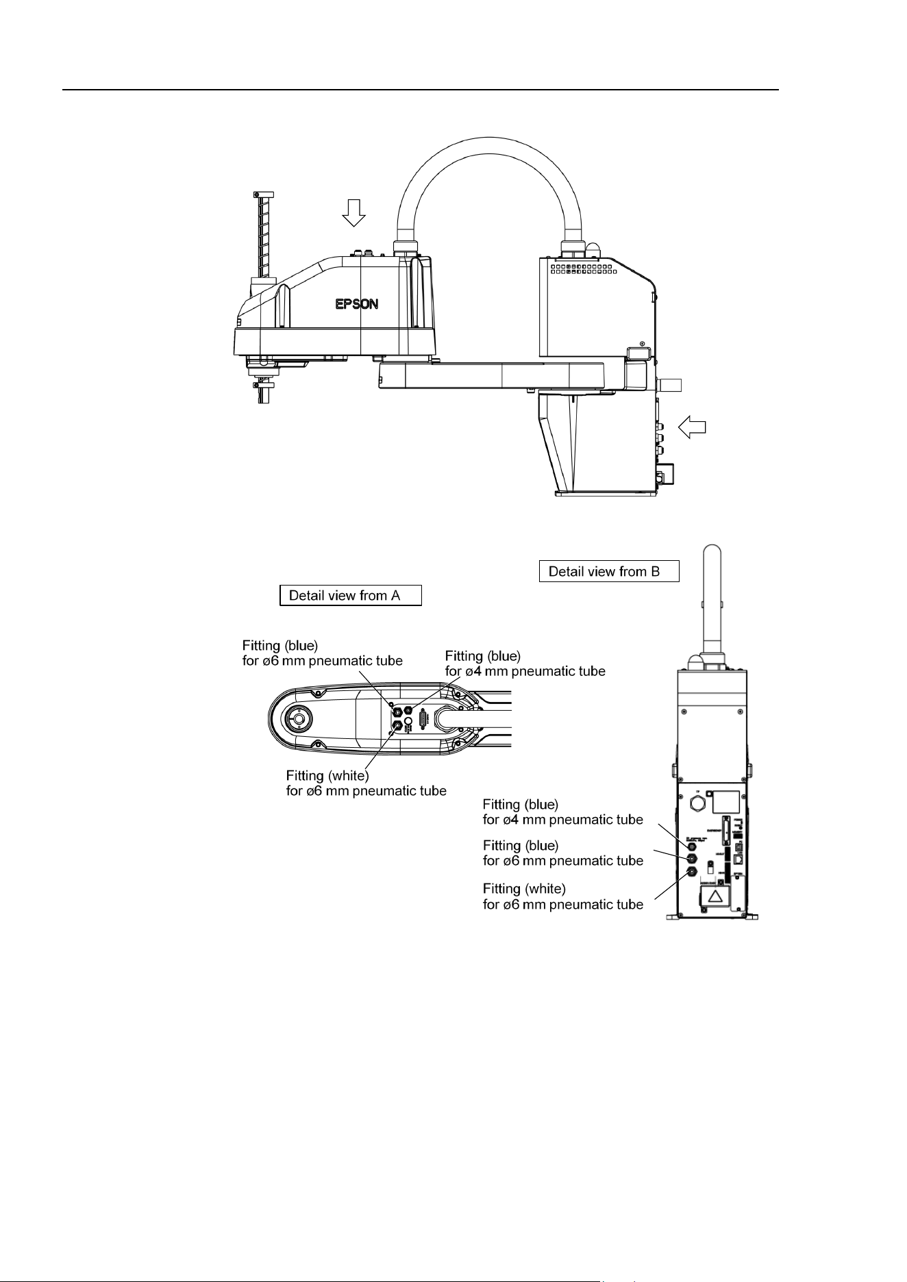
T3-B T6-B Manipulator 3. Environments and Installation
62 T-B series Rev.6
T6-B
A
B
T3-B T6-B Manipulator 3. Environments and Installation
T-B series Rev.6 63
3.9 Relocation and Storage
3.9.1 Precautions for Relocation and Storage
Observe the following when relocating, storing, and transporting the Manipulators.
Transportation, and installation shall be performed by personnel who has taken robot system
training held by us and suppliers and should conform to all national and local codes.
WARNING
■
Only authorized personnel
should perform sling work and operate a crane and a
forklift.
When these operations are performed by unauthorized personnel, it is
extremely
hazardous and may result in serious bodily injury and/or severe
equipment damage to the robot system.
CAUTION
■
Before relocating the Manipulator,
fold the arm and secure it tightly with a sheet to
prevent hands or fingers from
being caught in the Manipulator.
■
When removing the anchor bolts, support the Manipulator to prevent falling.
Removing the anchor bolts without support may result in a fall of the Manipulator,
and then get hands, fingers, or feet caught.
■
To carry the Manipulator, have two or more people to work on it and secure the
Manipulator to the delivery
equipment or hold the bottom of Arm #1 and the bottom
of the
base by hand. When holding the bottom of the base by hand, be very careful
not to get hands or fi
ngers caught.
■
Stabilize the Manipulator with your hands when hoist
ing it. Unstable hoisting is
extremely hazardous and may result in fall of the Manipulator.
When transporting the Manipulator for a long distance, secure it to the delivery equipment
so that the Manipulator cannot fall.
If necessary, pack the Manipulator in the same way as it was delivered.
When the Manipulator is used for a robot system again after long-term storage, perform a
test run to verify that it works properly, and then operate it thoroughly.
Transport and store the Manipulator in the range of Temperature: -20 to +60 °C, Humidity:
10 to 90% (no condensation).
When condensation occurs on the Manipulator during transport or storage, turn ON the
power only after the condensation dries.
Do not shock or shake the Manipulator during transport.
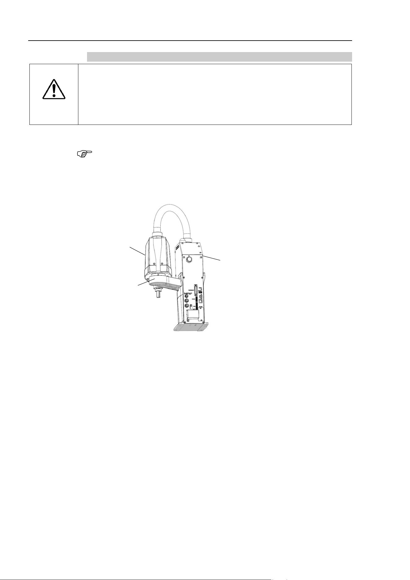
T3-B T6-B Manipulator 3. Environments and Installation
64 T-B series Rev.6
3.9.2 Relocation
CAUTION
■
Install
or relocate the Manipulator with two or more people.
The Manipulator
weigh
ts are as follows. Be careful not to get hands, fingers, or
feet caught and/or
have equipment damage
d by a fall of the Manipulator.
T3-B401S: Max.14kg: 31lbs.
T6-B602S: Max.21kg: 46lbs.
(1) Turn OFF the power on all devices and unplug the cables.
Remove the mechanical stops if using them to limit the motion range of Joints #1 and
#2. For details on the motion range, refer to “5.2 Motion Range Setting by
Mechanical Stops”.
(2) Cover the Arm #2 and Power Supply Unit with a sheet so that the arm will not be
damaged.
Power Supply Unit
Arm #2
Example of Arm Retaining Posture
Arm #1
(Illustration: T3-B401S)
NOTE
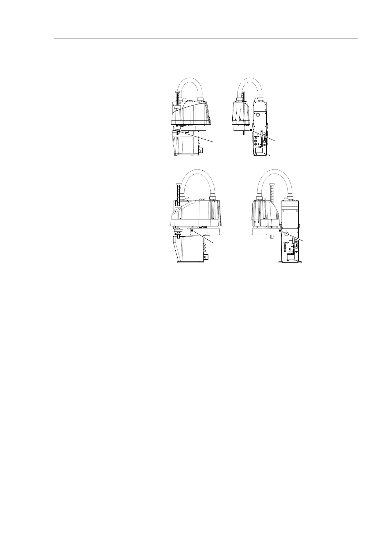
T3-B T6-B Manipulator 3. Environments and Installation
T-B series Rev.6 65
(3) Hold the bottom of Arm #1 by hand to unscrew the anchor bolts.
Then, remove the Manipulator from the base table.
T3-B401S
Center of gravity
Center of gravity
T6-B602S
Center of gravity
Center of gravity
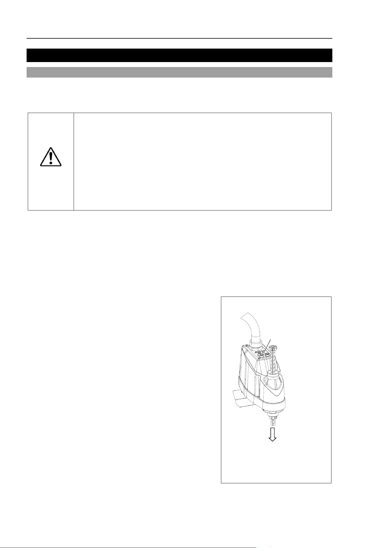
T3-B T6-B Manipulator 4. Setting of End Effectors
66 T-B series Rev.6
4. Setting of End Effectors
4.1 Attaching an End Effector
Create an end effector for your Manipulator. For details of attaching an end effector, refer
to “Hand Function Manual”
Before attaching an end effector, observe these guidelines.
CAUTION
■
If you use an end effector equipped with a gripper or chuck, connect wires and/or
pneumatic tubes
properly so that the gripper does not release the work piece when
the power to the robot system is turned OFF. Improper connection of the wires
and/or pneumatic tubes may damage the robot system and/or work piece as the
work piece is released when the Emer
gency Stop switch is pressed.
I/O outputs are configured at the factory so that they are automatically shut off (0)
by power disconnection, the Emergency Stop switch, or the safety features of the
robot system.
However, the I/O set in the hand function do
es not turn off (0) when the Reset
command is executed or in emergency stop.
Shaft
- Attach an end effector to the lower end of the shaft.
For the shaft dimensions, and the overall dimensions of the Manipulator, refer to “2.
Specifications”.
- Do not move the upper limit mechanical stop on the lower side of the shaft. Otherwise,
when “Jump motion” is performed, the upper limit mechanical stop may hit the
Manipulator, and the robot system may not function properly.
- Use a split muff coupling with an M4 bolt or larger to attach the end effector to the shaft.
Brake release switch
-
Joint #3 cannot be moved up/down by hand
because the solenoid brake is applied to the
joint while power to the robot system is turned
OFF.
This prevents the shaft from
hitting peripheral
equipment in the case that the shaft is lowered
by the weight of the end effector when the
power is disconnected during operation, or
when the motor is turned OFF even though the
power is turned ON.
To move Joint #3 up/down while attachi
ng an
end effector, turn ON the Manipulator and press
the brake release switch.
This button switch is a momentary
-type; the
brake is released only while the button switch is
being pressed.
Brake release switch
The shaft may be
lowered by the weight
of the end effector.
-
Be careful of the shaft while th
e brake release
switch is being pressed because the shaft may
be lowered by the weight of the end effector.

T3-B T6-B Manipulator 4. Setting of End Effectors
T-B series Rev.6 67
Layouts
- When you operate the manipulator with an end effector, the end effector may interfere
with the Manipulator because of the outer diameter of the end effector, the size of the
work piece, or the position of the arms. When designing your system layout, pay
attention to the interference area of the end effector.
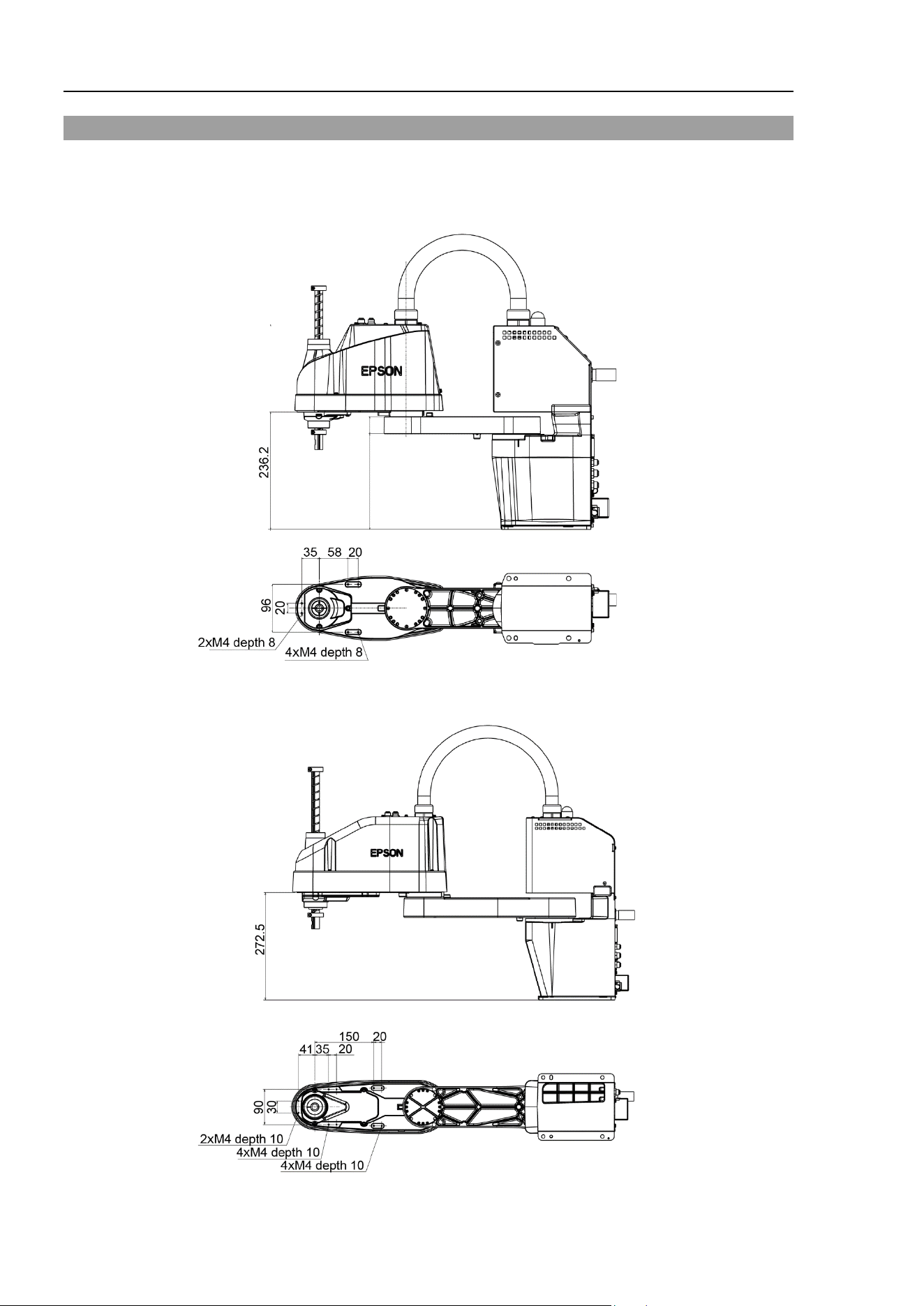
T3-B T6-B Manipulator 4. Setting of End Effectors
68 T-B series Rev.6
4.2 Attaching Cameras and Valves
The bottom of the Arm #2 has threaded holes as shown in the figure below. Use these holes
for attaching cameras, valves, and other equipment.
T3-B
From the base mounting face
T6-B
From the base mounting face
T3-B T6-B Manipulator 4. Setting of End Effectors
T-B series Rev.6 69
4.3 Weight and Inertia Settings
To ensure optimum Manipulator performance, it is important to make sure that the load
(weight of the end effector and work piece) and moment of inertia of the load are within the
maximum rating for the Manipulator, and that Joint #4 does not become eccentric.
If the load or moment of inertia exceeds the rating or if the load becomes eccentric, follow
the steps in “4.3.1Weight Setting” and “4.3.2 Inertia Setting” to set parameters.
Setting parameters makes the PTP motion of the Manipulator optimal, reduces vibration to
shorten the operating time, and improves the capacity for larger loads. In addition, it reduces
persistent vibration produced when the moment of inertia of the end effector and work piece
is larger than the default setting.
You can also set by following “Weight, Inertia, and Eccentricity/offset Measurement Utility”.
The following manual describes the details.
EPSON RC+ 7.0 User’s Guide
6.18.12 Weight, Inertia, and Eccentricity/offset Measurement Utility
4.3.1 Weight Setting
CAUTION
■
The total weight of the end effector and the work piece must not exceed T3
-B: 3kg
/ T6
-B: 6kg. The T-B series Manipulators are not designed to work with loads
exceeding T3
-B: 3kg / T6-B: 6kg.
Always set the Weight parameters according to the load. Setting
a value that is
smaller than the actual load may cause errors, excessive shock and insufficient
function of the Manipulator. Also, the life cycle of parts is shortened and positional
gap due to belt tooth bumping occurs.
The acceptable weight capacity (end effector and work piece) in T-B series:
T3-B: default rating 1 kg, the maximum 3 kg
T6-B: default rating 2 kg, the maximum 6 kg
When the load (weight of the end effector and work piece) exceeds the rating, change the
setting of Weight parameter.
After the setting is changed, the maximum acceleration/deceleration speed of the robot
system at PTP motion corresponding to the “Weight Parameter” is set automatically.
Load on the Shaft
The load (weight of the end effector and work piece) on the shaft
can be set by Weight
parameter.
Enter a value into the [Weight] text box on the [WEIGHT] panel ([Tools]
-
[Robot Manager]).
(You may also execute the WEIGHT command from the [Command Window].)
EPSON
RC+
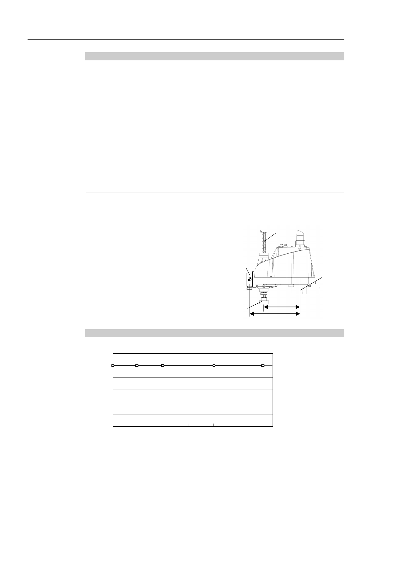
T3-B T6-B Manipulator 4. Setting of End Effectors
70 T-B series Rev.6
Load on the Arm
When you attach a camera or other devices to the arm, calculate the weight as the equivalent
of t
he shaft. Then, add this to the load and enter the total weight to the Weight parameter
Equivalent Weight Formula
When you attach the equipment to the rotation center of
Joint
#2:
When you attach the equipment to the end of Arm #2:
W
M
= M (L
1
)
2
/(L
1
+L
2
)
2
W
M
= M (L
M
)
2
/(L
2
)
2
W
M
M
L
1
L
2
L
M
: equivalent weight
: weight of camera etc.
: length of Arm #1
: length of Arm #2
: distance from rotation center of Joint #2 to center of gravity
of camera etc.
<Example>
A “1 kg” camera is attached to the end of the T3
-B
series arm (225 mm away from
the rotation center of Joint #2) with a load weight of “1 kg”.
M=1
L
2
=175
L
M
=225
W
M
=1×225
2
/175
2
=1.653 1.7 (round up)
W+W
M
=1+1.7=2.7
Enter “2.7” for the Weight Parameter.
Shaft
Weight of
camera
M=1kg
W=1kg
L
2
=175 mm
L
M
=225 mm
Joint #2
Automatic speed setting by Weight
T3-B
120
100
80
60
40
20
2.5
3 (kg)
(%)
100
100
100
End effector end parameter
100
0 0.5
1
2
1.5
* The percentage in the graph is based on the speed at rated weight (1 kg) as 100%.
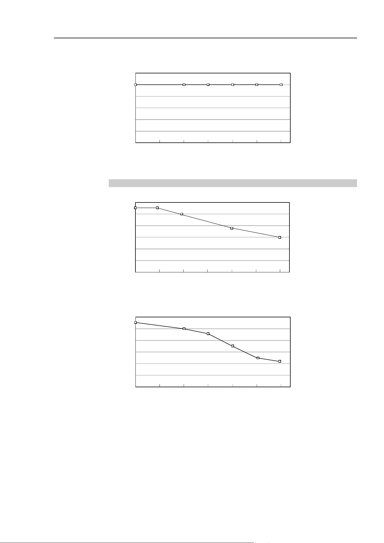
T3-B T6-B Manipulator 4. Setting of End Effectors
T-B series Rev.6 71
T6-B
120
100
80
60
40
20
0 1 2 3 4 5 6 (kg)
(%)
100
100
100
100
End effector weight parameter
100
* The percentage in the graph is based on the speed at rated weight (2 kg) as 100%.
Automatic acceleration/deceleration setting by Weight
T3-B
120
100
80
60
40
20
0 0.5 1 1.5 2 2.5 3 (kg)
(%)
100
110
75
End effector weight
parameter
60
110
* The percentage in the graph is based on the speed at rated weight (1 kg) as 100%.
T6-B
120
100
80
60
40
20
0 1 2 3 4 5 6 (kg)
(%)
100
110
93
50
End effector weight parameter
70
45
* The percentage in the graph is based on the speed at rated weight (2 kg) as 100%.
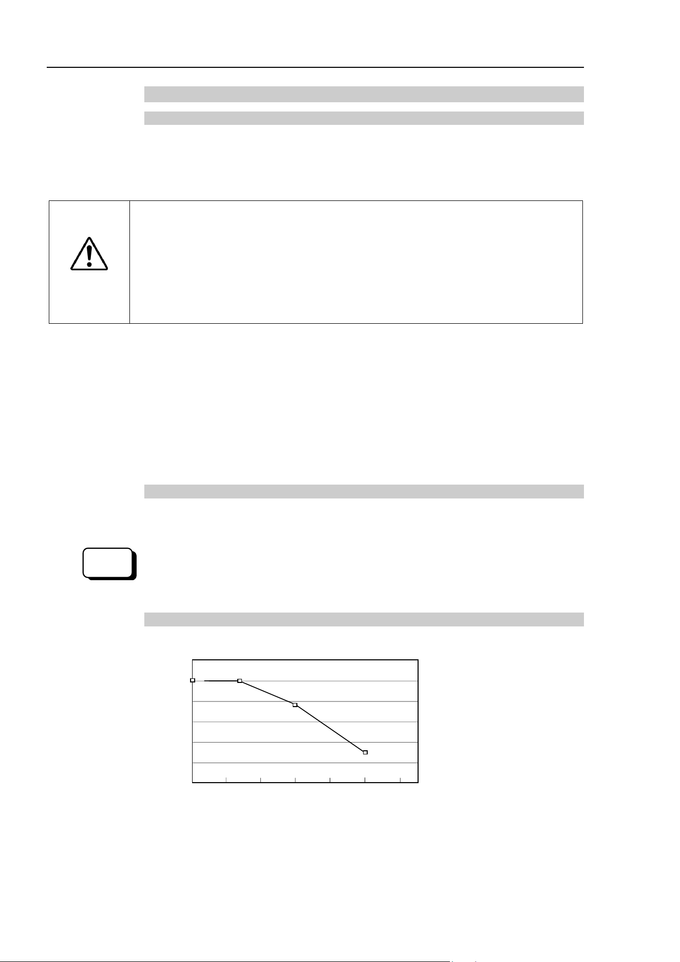
T3-B T6-B Manipulator 4. Setting of End Effectors
72 T-B series Rev.6
4.3.2 Inertia Setting
Moment of Inertia and the Inertia Setting
The moment of inertia is defined as “the ratio of the torque applied to a rigid body and its
re
sistance to motion”. This value is typically referred to as “the moment of inertia”, “inertia”,
or “GD
2
”. When the Manipulator operates with additional objects (such as an end effector)
attached to the shaft, the moment of inertia of load must be considered.
CAUTION
■
The moment of inertia of the load (weight of the end effector and work piece) must
be T3
-B: 0.01 kg·m
2
/ T6-B: 0.08 kg·m
2
or less. The T-B series Manipulators are
not designed to work with a moment of inertia exceeding T3
-B: 0.01 kg·m
2
/ T6-B:
0.08 kg
·m
2
. Always set the Weight parameters according to the load. Setting a
value that is smaller than the actual load may cause er
rors, excessive shock and
insufficient function of the Manipulator. Also, the life cycle of parts is shortened
and positional gap due to belt tooth bumping occurs.
The acceptable moment of inertia of load for a T-B series Manipulator:
T3-B: default rating 0.003 kg·m
2
, the maximum 0.01 kg·m
2
T6-B: default rating 0.01 kg·m
2
, the maximum 0.08 kg·m
2
When the moment of inertia of the load exceeds the rating, change the setting of the moment
of inertia parameter of the Inertia command. After the setting is changed, the maximum
acceleration/deceleration speed of Joint #4 at PTP motion corresponding to the “moment of
inertia” value is set automatically.
Moment of inertia of load on the shaft
The moment of inertia of load (weight of the end effector and work piece) on the shaft can
be s
et by the “moment of inertia” parameter of the Inertia command.
EPSON
RC+
Enter a value into the [Load inertia:] text box on the [Inertia] panel ([Tools]
-
[Robot
Manager]). (You may also execute the
Inertia command from the [Command Window].)
Automatic acceleration/deceleration setting of Joint #4 by Inertia (moment of inertia)
T3-B
0 0.002 0.004 0.006 0.008 0.01 0.012 (kg·m
2
)
120
100
80
60
40
20
(%)
100
100
30
75
Inertia moment parameter
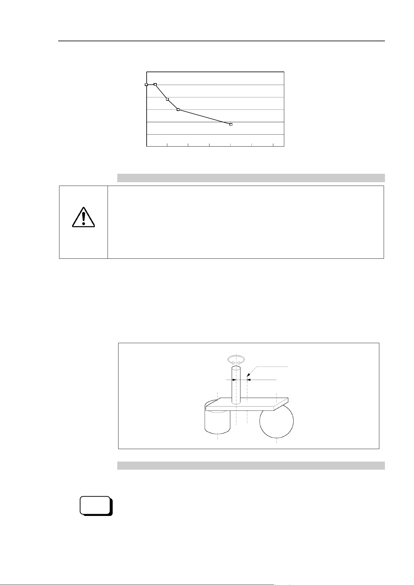
T3-B T6-B Manipulator 4. Setting of End Effectors
T-B series Rev.6 73
T6-B
0 0.020 0.040 0.060 0.080 0.1
(kg·m
2
)
120
100
80
60
40
20
(%)
100
Inertia moment parameter
75
60
35
Eccentric Quantity and the Inertia Setting
CAUTION
■
The eccentric quantity of load (weight of the end effector and work piece) must be
T3
-B: 100mm / T6-B: 150mm or less. The T-B series Manipulators are not
designed to work with eccentric quantity exceeding T3
-B: 100mm / T6-B: 150mm.
Always set the
Weight parameters according to the load. Setting a value that is
smaller than the actual load may cause errors, excessive shock and insufficient
function of the Manipulator. Also, the life cycle of parts is shortened and positional
gap due to belt tooth b
umping occurs.
The acceptable eccentric quantity of load in T-B series:
T3-B: default rating 0 mm, at the maximum: 100 mm
T6-B: default rating 0 mm, at the maximum: 150 mm
When the eccentric quantity of load exceeds the rating, change the setting of eccentric
quantity parameter of Inertia command. After the setting is changed, the maximum
acceleration/deceleration speed of the Manipulator at PTP motion corresponding to the
“eccentric quantity” is set automatically.
Position of load
’
s center of gravity
Rotation center
Eccentric quantity
Eccentric Quantity
Eccentric quantity of load on the shaft
The eccentric quantity of load (weight of the end effector and work piece) on the shaft can
be s
et by “eccentric quantity” parameter of Inertia command.
EPSON
RC+
Enter a value into the [Eccentricity:] text box on the [Inertia] panel ([Tools]
-
[Robot
Manager]). (You may also execute the Inertia command from the [Command Window].)
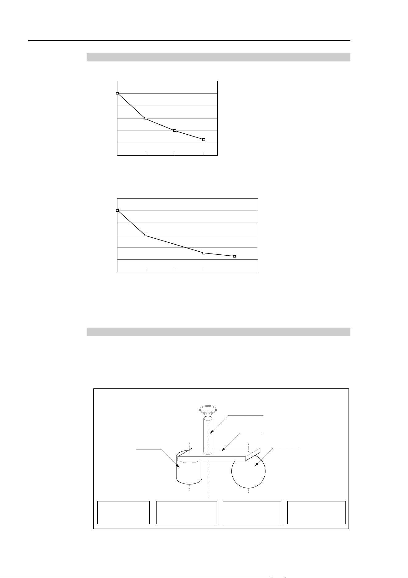
T3-B T6-B Manipulator 4. Setting of End Effectors
74 T-B series Rev.6
Automatic acceleration/deceleration setting by Inertia (eccentric quantity)
T3-B
120
100
80
60
40
20
0 50 75 100 (mm)
60
40
25
(%)
100
Eccentricity setting
T6-B
120
100
80
60
40
20
0 50 75 100 150 (mm)
70
30
20
(%)
100
Eccentricity setting
* The percentage in the graph is based on the acceleration / deceleration at rated eccentricity (0
mm) as 100%.
Calculating the Moment of Inertia
Refer to the following examples of formulas
to calculate the moment of inertia of load (end
effector with work piece).
The moment of inertia of the entire load is calculated by the sum of each part (a), (b), and
(c).
Work piece (b)
Work piece (c)
End effector (a)
Joint #3 shaft
Rotation center
Moment of inertia
of end effector (a)
=
Moment of inertia
of work piece (b)
+
Moment of inertia
of work piece (c)
+
Whole moment
of inertia
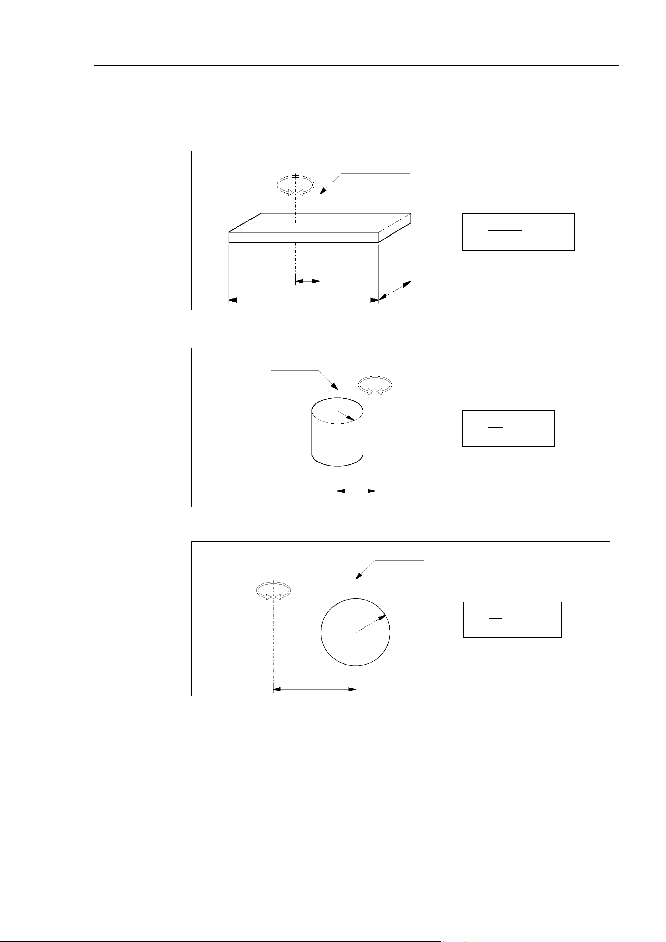
T3-B T6-B Manipulator 4. Setting of End Effectors
T-B series Rev.6 75
The methods for calculating the moment of inertia for (a), (b), and (c) are shown below.
Calculate the total moment of inertia using the basic formulas.
(a) Moment of inertia of a rectangular parallelepiped
h
b
L
m
Rectangular parallelepiped’s center of gravity
Rotation center
m
+ m × L
2
b
2
+ h
2
12
(b) Moment of inertia of a cylinder
m
+ m × L
2
r
2
2
m
L
r
Cylinder’s center of gravity
Rotation center
(c) Moment of inertia of a sphere
m
r
2
+ m × L
2
2
5
Sphere’s center of gravity
r
m
L
Rotation center
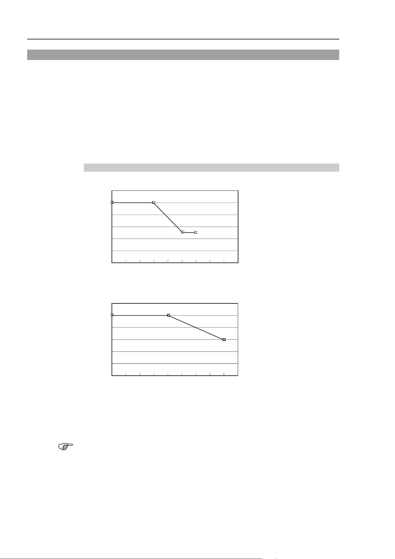
T3-B T6-B Manipulator 4. Setting of End Effectors
76 T-B series Rev.6
4.4 Precautions for Auto Acceleration/Deceleration of Joint #3
When you move the Manipulator in horizontal PTP motion with Joint #3 (Z) at a high
position, the motion time will be faster.
When Joint #3 gets below a certain point, then auto acceleration/deceleration is used to
reduce acceleration/deceleration. (Refer to the figures below) The higher the position of the
shaft is, the faster the motion acceleration/deceleration is. However, it takes more time to
move Joint #3 up and down. Adjust the position of Joint #3 for the Manipulator motion after
considering the relation between the current position and the destination position.
The upper limit of Joint #3 during horizontal motion using Jump command can be set by the
LimZ command.
Automatic acceleration/deceleration vs. Joint #3 position
T3-B
100
100
50
50
120
100
80
60
40
20
0 -50 -100 -150 -200 (mm)
(%)
Shaft height
T6-B
100
100
60
120
100
80
60
40
20
0 -50 -100 -150 -200 (mm)
(%)
Shaft height
* Figures on the graph (%) are the proportion to the acceleration/deceleration speed
at the shaft upper limit position.
When moving the Manipulator horizontally while the shaft is being lowered, it may cause
over-shoot at the time of final positioning.
NOTE
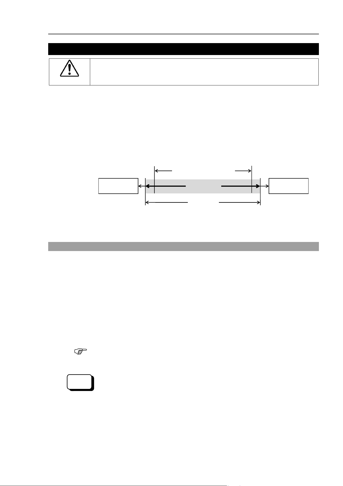
T3-B T6-B Manipulator 5. Motion Range
T-B series Rev.6 77
5. Motion Range
CAUTION
■
When setting up the motion range for safety, both the pulse range and mechanical
stops must always be set at the same time.
The motion range is preset at the factory as explained in “5.4 Standard Motion Range”. That
is the maximum motion range of the Manipulator.
There are three methods for setting the motion range described as follows:
1. Setting by pulse range (for all joints)
2. Setting by mechanical stops (for Joints #1 to #3)
3. Setting the Cartesian (rectangular) range in the X, Y coordinate system of the
Manipulator (for Joints #1 and #2)
Mechanical
stop
Rectangular range setting
Pulse range
Motion range
Mechanical
stop
When the motion range is changed due to layout efficiency or safety, follow the descriptions
in 5.1 to 5.3 to set the range.
5.1 Motion Range Setting by Pulse Range (for All Joints)
Pulses are the basic unit of Manipulator motion. The motion range of the Manipulator is
controlled by the pulse range between the pulse lower limit and upper limit of each joint.
Pulse values are read from the encoder output of the servo motor.
For the maximum pulse range, refer to the following sections.
The pulse range must be set inside of the mechanical stop range.
5.1.1 Max. Pulse Range of Joint #1
5.1.2 Max. Pulse Range of Joint #2
5.1.3 Max. Pulse Range of Joint #3
5.1.4 Max. Pulse Range of Joint #4.
Once the Manipulator receives an operating command, it checks whether the target position
specified by the command is within the pulse range before operating. If the target position
is out of the set pulse range, an error occurs and the Manipulator does not move.
The pulse range can be set on
the [Range] panel shown by selecting [Tools]-[Robot
Manager]. (You may also execute the Range command from the [Command Window].)
EPSON
RC+
NOTE
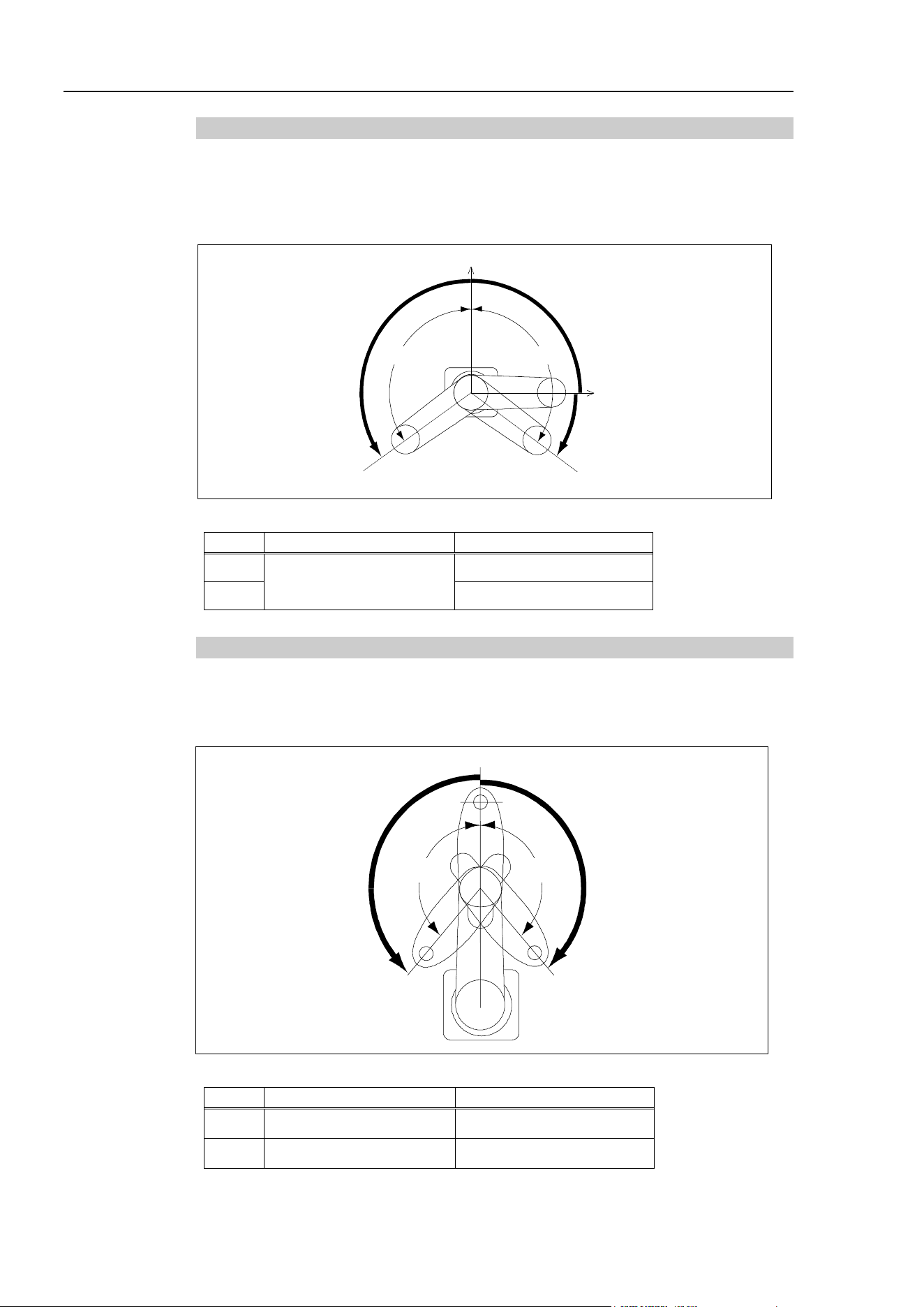
T3-B T6-B Manipulator 5. Motion Range
78 T-B series Rev.6
5.1.1 Max. Pulse Range of Joint #1
The 0 (zero) pulse position of Joint #1 is the position where Arm #1 faces toward the positive
(+) direction on the X-coordinate axis.
When the 0 pulse is a starting point, the counterclockwise pulse value is defined as the
positive (+) and the clockwise pulse value is defined as the negative (-).
+Y
+X 0 pulse
+ B
− B
+ A
− A
A: Max. Motion Range
B: Max. Pulse Range
T3-B
± 132°
− 95574 to 505174 pulse
T6-B
−152918 to 808278 pulse
5.1.2 Max. Pulse Range of Joint #2
The 0 (zero) pulse position of Joint #2 is the position where Arm #2 is in-line with Arm #1.
With the 0 pulse as a starting point, the counterclockwise pulse value is defined as the
positive (+) and the clockwise pulse value is defined as the negative (-).
− B
+ B
0 pulse
− A
+ A
A: Max. Motion Range
B: Max. Pulse Range
T3-B
± 141° ± 320854 pulse
T6-B
± 150° ± 341334 pulse
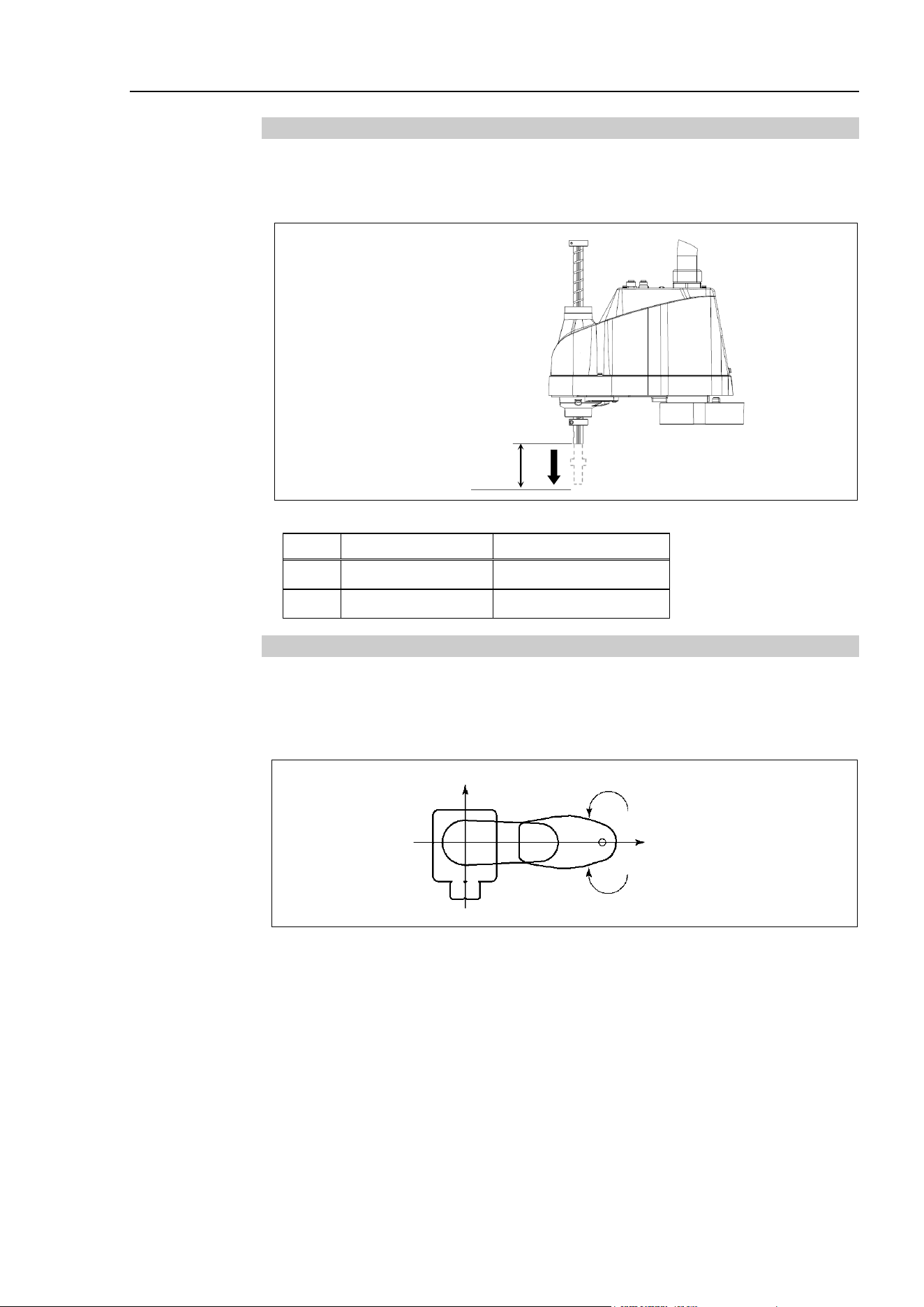
T3-B T6-B Manipulator 5. Motion Range
T-B series Rev.6 79
5.1.3 Max. Pulse Range of Joint #3
The 0 (zero) pulse position of Joint #3 is the position where the shaft is at its upper limit.
The pulse value is always negative because Joint #3 always moves lower than the 0 pulse
position.
Upper limit: 0 pulse
Joint #3 Stroke Lower Limit Pulse
T3-B 150 mm
−187734 pulse
T6-B 200 mm
−245760 pulse
5.1.4 Max. Pulse Range of Joint #4
The 0 (zero) pulse position of Joint #4 is the position where the flat near the end of the shaft
faces toward the end of Arm #2. With the 0 pulse as a starting point, the counterclockwise
pulse value is defined as the positive (+) and the clockwise pulse value is defined as the
negative (-).
+X
T3-B: 0 ± 74130 pulse
T6-B: 0 ± 245760 pulse
+Y
Clockwise (-value)
Counterclockwise (+value)
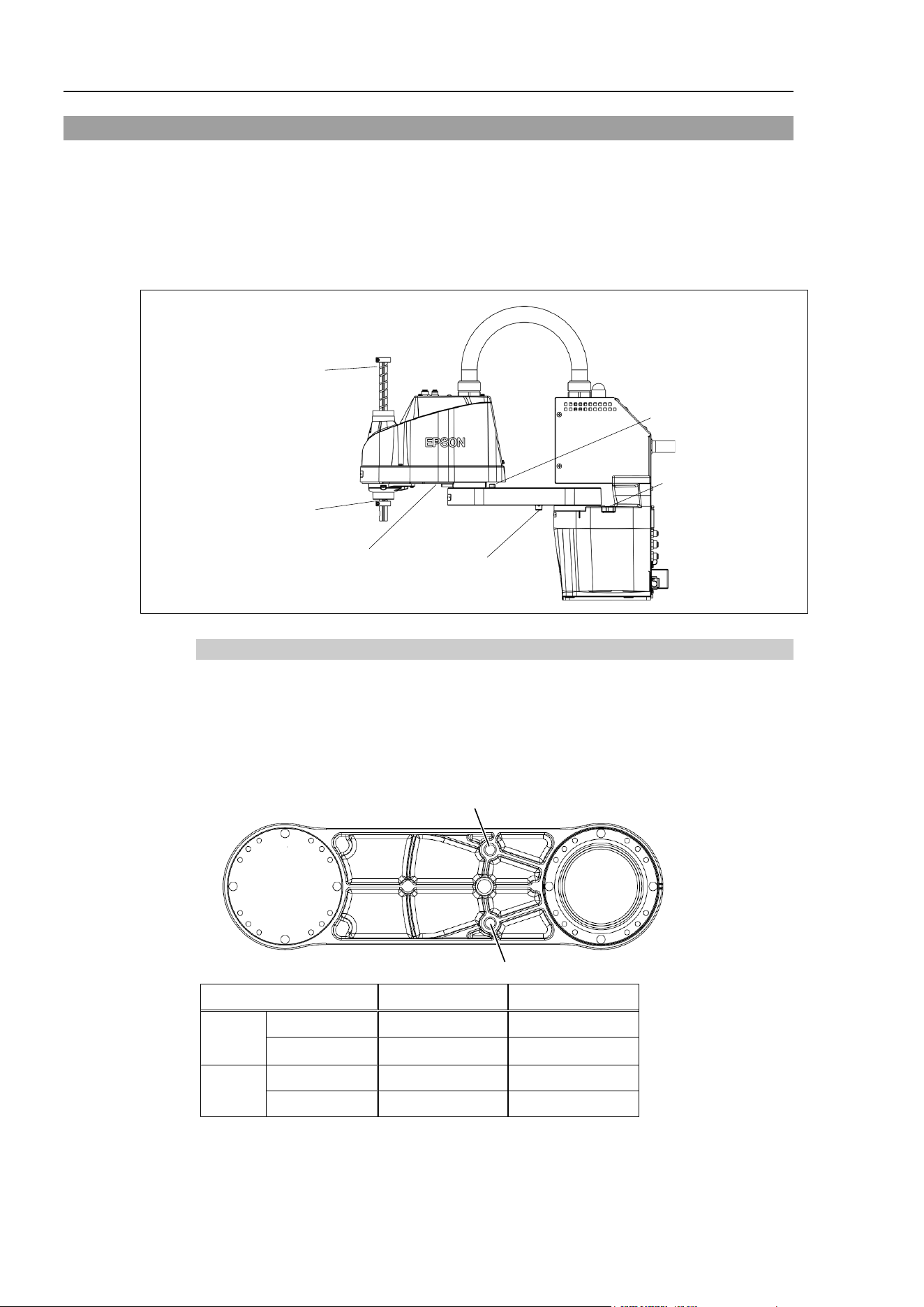
T3-B T6-B Manipulator 5. Motion Range
80 T-B series Rev.6
5.2 Motion Range Setting by Mechanical Stops
Mechanical stops physically limit the absolute area that the Manipulator can move.
Both Joints #1 and #2 have threaded holes in the positions corresponding to the angle for
the mechanical stop settings. Install the bolts in the holes corresponding to the angle that
you want to set.
Joints #3 can be set to any length less than the maximum stroke.
Mechanical stop of Joint #2
(Fixed)
Mechanical stop of
Joint #1 (Adjustable)
Mechanical stop of Joint #3
(Lower limit mechanical stop)
(Do not move the upper
limit mechanical stop.)
Mechanical stop of
Joint #1 (Fixed)
Mechanical stop of
Joint #2 (Adjustable)
5.2.1 Setting the Mechanical Stops of Joints #1 and #2
Both Joints #1 and #2 have threaded holes in the positions corresponding to the angle for
the mechanical stop settings. Install the bolts in the holes corresponding to the angle that
you want to set.
Install the bolts for the mechanical stop to the following position.
Joint #1 Mechanical Stops (Views from the bottom of Arm #1)
a
b
a
b
T3-B
Setting Angle
110
°
−
110
°
Pulse Value
455112 pulse
−
45512 pulse
T6-B
Setting Angle
115
°
−
115
°
Pulse Value
466489 pulse
−
56889 pulse
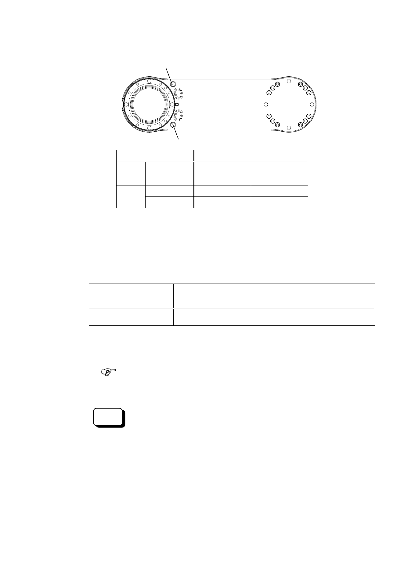
T3-B T6-B Manipulator 5. Motion Range
T-B series Rev.6 81
Joint #2 Mechanical Stops (Views from the top of Arm #1)
b
a
a
b
T3-B
Setting Angle
120
°
−
120
°
Pulse Value
273066pulse
−
273066pulse
T6-B
Setting Angle
125
°
−
125
°
Pulse Value
284444pulse −284444pulse
(1)
Turn OFF the
Manipulator.
(2)
Install a hexagon socket head cap bolt into the hole corresponding to the setting angle,
and tighten it.
T3
-B Joint #2 only
Remove the user plate on the arm cover.
For details, refer to T-B series Maintenance Manual “7. Cover”.
Joint
Hexagon socket
head cap bolt
(fully threaded)
The number
of bolts
Strength
Recommended
tightening torque
1
M8×10
All screws
One for each
One side
Equivalent to ISO898-1
property class 10.9 or 12.9
12.3 N⋅m (125 kgf⋅cm)
(3)
Turn ON the
Manipulator.
(4)
Set the pulse range corresponding to the new positions of the mechanical stops.
Be sure to set the pulse range inside the positions of the mechanical stop range.
Example:
Using T3-B401S
The angle of Joint #1 is set from –110° to +110°.
The angle of Joint #2 is set from -120° to +120°.
Execute the following commands from the [Command Window]
>JRANGE 1, -45512, 455112 ' Sets the pulse range of Joint #1
>JRANGE 2,- 273066, 273066 ' Sets the pulse range of Joint #2
>RANGE ' Checks the setting using Range
-45512, 455112, -273066, 273066, -187734
,0, -74130, 74130
(5)
Move the arm by hand until it touches the mechanical stops, and make sure that the arm
does no
t hit any peripheral equipment during operation.
EPSON
RC+
NOTE
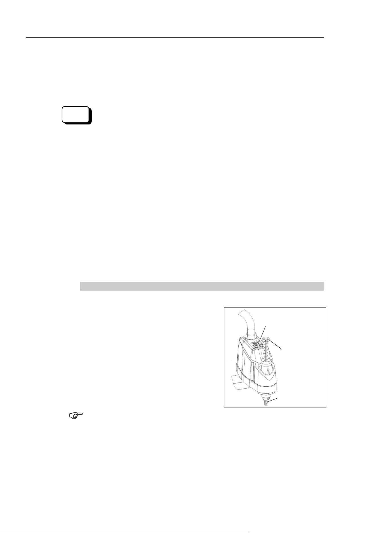
T3-B T6-B Manipulator 5. Motion Range
82 T-B series Rev.6
(6)
Operate the joint changed at low speeds until it reaches the positions of the minimum
and maximum pulse range. Make sure that the arm does not hit the mechanical stops.
(Check the position of the
mechanical stop and the motion range you set.)
Example: Using T3-B401S
The angle of Joint #1 is set from -110° to +110°.
The angle of Joint #2 is set from -120° to +120°.
Execute the following commands from the [Command Window].
>MOTOR ON ' Turns ON the motor
>POWER LOW ' Enters low-power mode
>SPEED 5 ' Sets at low speeds
>PULSE -45512,0,0,0 ' Moves to the min. pulse position of Joint #1
>PULSE 455112,0,0,0 ' Moves to the max. pulse position of Joint #1
>PULSE 204800,-273066,0,0 ' Moves to the min. pulse position of Joint #2
>PULSE 204800,273066,0,0 ' Moves to the max. pulse position of Joint #2
The Pulse command (Go Pulse command) moves all joints to the specified positions at
the same time. Specify safe positions after considering motion of not only the joints
whose pulse range have been changed, but also other joints.
In this example, Joint #1 is moved to the center of its motion range (pulse value:
204800) when checking Joint #2.
If the arm is hitting the mechanical stops or if an error occurs after the arm hits the
mechanical stops, either reset the pulse range to a narrower setting or extend the
positions of the mechanical stops within the limit.
5.2.2 Setting the Mechanical Stop of Joint #3
(1)
Turn ON the Manipulator and turn OFF the motors using the Motor OFF command.
(2)
Push up the shaft while pressing the brake
release switch.
Do not push the shaft up to its upper limit or it
will be difficult for the arm top
cover to be
removed. Push the shaft up to a position where
the Joint #3 mechanical stop can be changed.
Lower limit
mechanical
stop screw
T3-B:M3×10
T6-B:M4×15
Brake release switch
Shaft
When you press the brake release
switch
, the shaft may lower due to the weight of the
end effector. Be sure to hold the shaft by hand while pressing the
button.
(3)
Turn OFF the Manipulator.
(4)
Loosen the lower limit mechanical stop screw (T3
-B: M3×10, T6-B: M4×15).
EPSON
RC+
NOTE
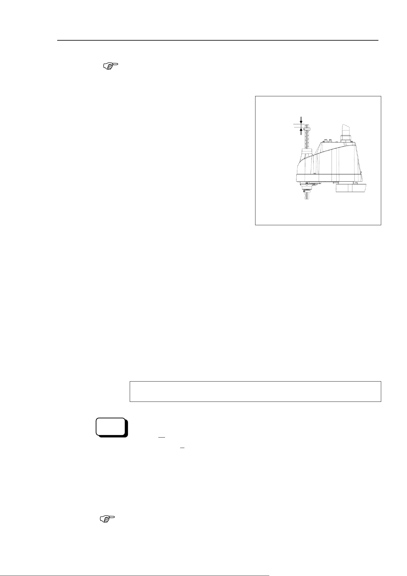
T3-B T6-B Manipulator 5. Motion Range
T-B series Rev.6 83
A mechanical stop is mounted on both the top and bottom of Joint #3. However, only the
position of the lower limit mechanical stop on the top can be changed. Do not remove
the upper limit mechanical stop on the bottom because the calibration point of Joint #3
is specified using the stop.
(5)
The upper end of the shaft defines the
maximum stroke. Move the lower limit
mechanical stop down by the length you
want to limit the stroke.
For example, when the lower limit
mechanical stop is set
at “150 mm” stroke,
the lower limit Z coordinate value is “
-
150
”. To change the value to “-130”,
move the lower limit mechanical stop
down “20 mm”. Use calipers to measure
the distance when adjusting the
mechanical stop.
Measure
this distance.
(
6)
Firmly tighten the lower limit mechanical stop screw (T3
-B: M3×10, T6-B: M4×15).
Recommended tightening torque:
T3-B: 2.4±0.1 N⋅m
T6-B: 5.5±0.25 N⋅m
(7)
Turn ON the Manipulator.
(8)
Move Joint #3 to its lower limit while pressing the brake release switch, and then check
the lower limit position. Do not lower the mechanical stop too far. Otherwise, the joint
may not reach a target position.
(9)
Calculate the lower limit pulse value of the pulse range using the formula shown below
and set th
e value.
The result of the calculation is always negative because the lower limit Z coordinate
value is negative.
Lower limit of pulse (pulse)
= lower limit Z coordinate value (mm) / Joint #3 resolution (mm/pulse)**
** For the Joint #3 resolution, refer to “Appendix A: Specifications
”.
Execute the following command from the [Command Window]. Enter the calculated
value in X.
>JRANGE 3,X,0 ' Sets the pulse range of Joint #3
(10)
Using the Pulse command (Go Pulse command), move Joint #3 to the lower limit
position of the pulse range at low speed. If the mechanical stop range is less than the
pulse range, Joint #3 will hit the mechanical stop and an error will occur. When the error
occurs, either change the pulse range to a lower setting or extend the position of the
mechanical stop within the limit.
If it is difficult to check whether Joint #3 hits a mechanical stop, turn OFF the
Manipulator and lift the arm top cover to check the condition causing the problem from
the side.
EPSON
RC+
NOTE
NOTE
T3-B T6-B Manipulator 5. Motion Range
84 T-B series Rev.6
Execute the following commands from the [Command Window]. Enter the value
calculated in Step (9) in X.
>MOTOR ON ' Turns ON the motor
>SPEED 5 ' Sets low speed
>PULSE 0,0,X,0
' Moves to the lower limit-pulse position of Joint #3.
(In this example, all pul
ses except those for Joint #3 are “0”.
Substitute these “0s” with the other pulse values specifying
a position where there is no interference even when lowering
Joint #3.)
5.3 Setting the Cartesian (Rectangular) Range in the XY
Coordinate System of the Manipulator (for Joints #1 and #2)
Use this method to set the upper and lower limits of the X and Y coordinates.
This setting is only enforced by software. Therefore, it does not change the physical range.
The maximum physical range is based on the position of the mechanical stops.
Set the XYLim setting on the [XYZ Limits] panel shown by selecting [Tools]
-
[Robot
Manager].
(You may also execute the XYLim command from the [Command Window].)
5.4 Standard Motion Range
The following “motion range” diagrams show the standard (maximum) specification. When
each Joint motor is under servo control, the center of Joint #3’s (shaft’s) lowest point moves
in the areas shown in the figure.
“Area limited by mechanical stop” is the area where the center of Joint #3’s lowest point
can be moved when each joint motor is not under servo control.
“Mechanical stop” sets the limited motion range so that the center of Joint #3 cannot move
beyond the area mechanically.
“Maximum space” is the area that contains the farthest reach of the arms. If the maximum
radius of the end effector is over 60 mm, add the “Area limited by mechanical stop” and
“radius of the end effector”. The total value is specified as the maximum area.
For the motion area figures, refer to “3.3 Mounting Dimensions”.
EPSON
RC+
EPSON
RC+

T3-B T6-B Manipulator 6. Operation Mode & LED
T-B series Rev.6 85
6. Operation Mode & LED
6.1 Overview
The Robot system has three operation modes.
TEACH mode This mode enables point data teaching and checking close to the
Manipulator using the Teach Pendant.
In this mode the Manipulator operates in Low power status.
AUTO mode
This mode enables automatic operation (program execution) of the
Robot system for the manufacturing operation, and also programming,
debug, adjustment, and maintenance of the Robot system.
This mode cannot operate the Manipulators or run programs with the
Safety Door open.
TEST mode
This mode enables program verification while the Enab
le Switch is
held down and the safeguard is open.
This is a low speed program verification function (T1: manual
deceleration mode) which is defined in Safety Standards.
This mode can operate the specified Function with multi-task / single-
task, multi-manipulator / single-manipulator at low speed.
6.2 Switch Operation Mode
Change the operation mode using the mode selector key switch on the Teach Pendant.
TEACH mode Turn the mode selector key switch to “Teach” for TEACH mode.
Switching to TEACH mode pauses the program if it was running.
The operating manipulator stops by Quick Pause.
AUTO mode Turn the mode selector key switch to “Auto” and turn on the latch
release input signal for AUTO mode.
TEST mode Turn the mode selector key switch to “Teach” for “TEACH” mode.
Push <F1> key-[Test Mode] in [Jog & Teach] dialog of TEACH
mode. The mode will be changed to TEST
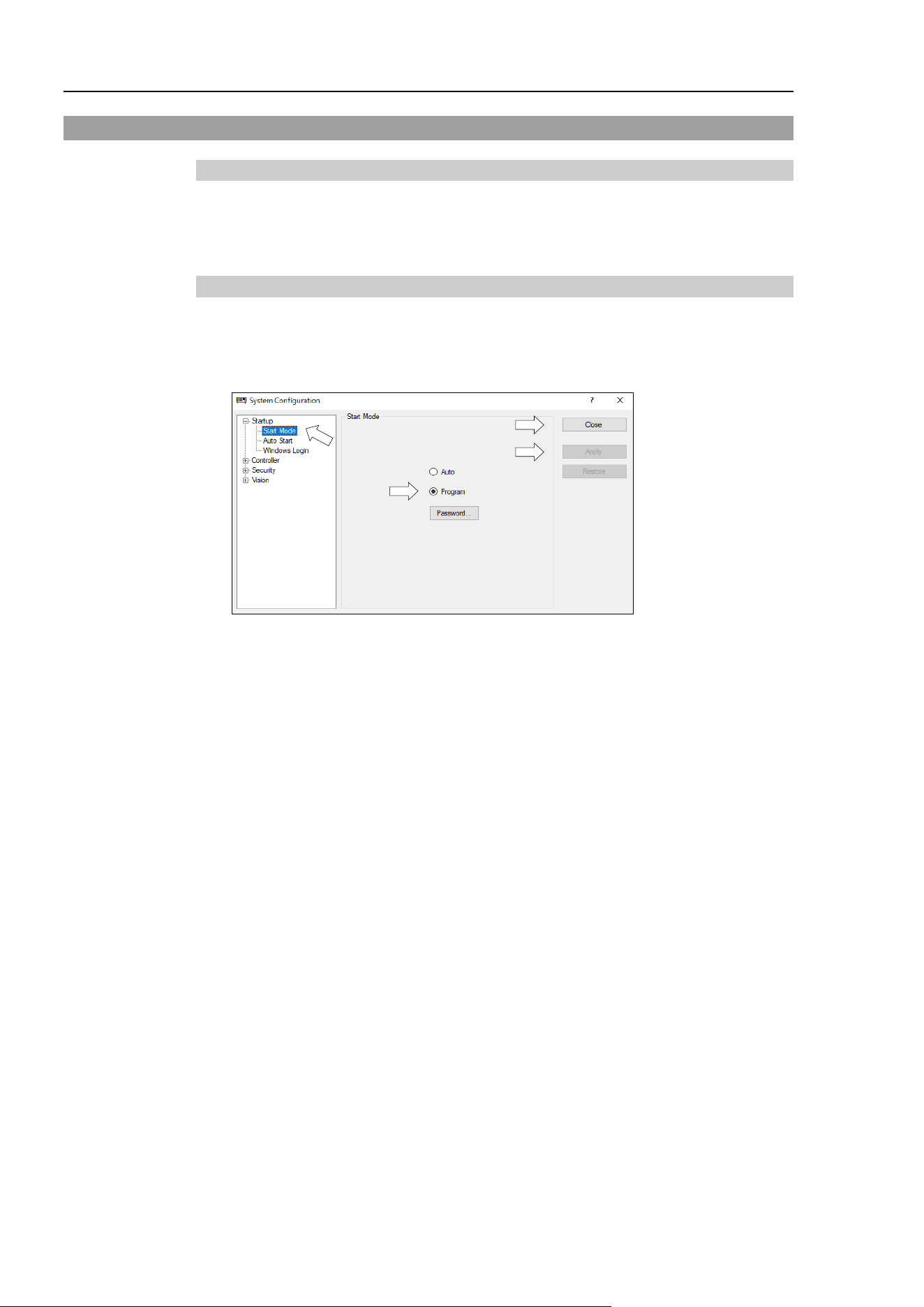
T3-B T6-B Manipulator 6. Operation Mode & LED
86 T-B series Rev.6
6.3 Program Mode (AUTO)
6.3.1 What is Program Mode (AUTO)?
Program mode is for programming, debug, adjustment, and maintenance of the Robot
system.
Follow the procedures below to switch to the Program mode.
6.3.2 Setup from EPSON RC+ 7.0
Switch the mode to Program mode from the EPSON RC+ 7.0.
(1) Select EPSON RC+ 7.0 menu-[Setup]-[System Configuration] to display the [System
Configuration] dialog.
(2)
(5)
(3)
(4)
(2) Select [Startup].
(3) Select [Start mode]-<Program> button.
(4) Click the <Apply> button.
(5) Click the <Close> button.
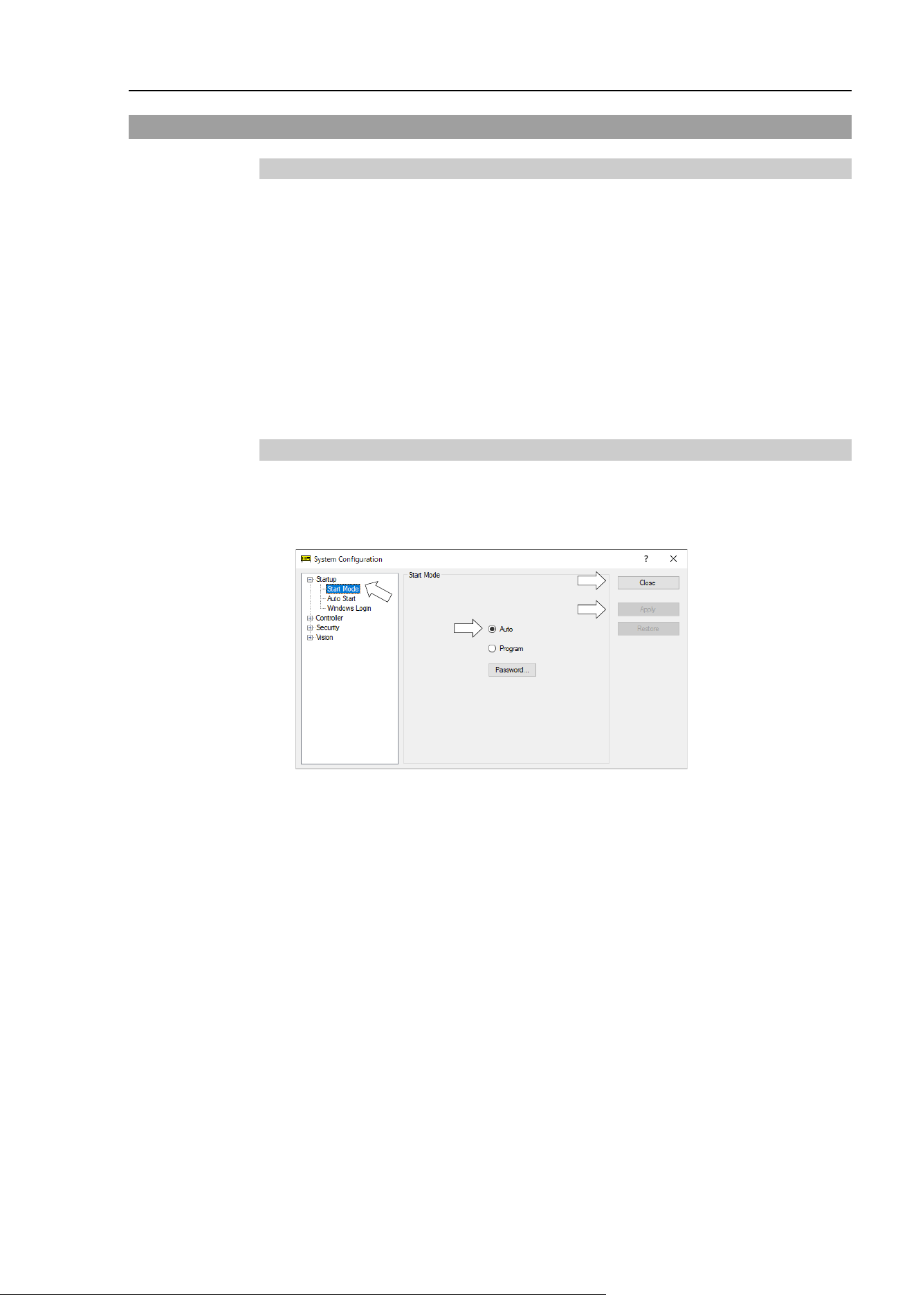
T3-B T6-B Manipulator 6. Operation Mode & LED
T-B series Rev.6 87
6.4 Auto Mode (AUTO)
6.4.1 What is Auto mode (AUTO)?
Auto mode (AUTO) is for automatic operation of the Robot system.
Procedures for switching to the Auto mode (AUTO) are the following.
A : Set the start mode of the EPSON RC+ 7.0 to “Auto” and start the EPSON RC+
7.0.
(Reference: 6.3.2 Setup from EPSON RC+ 7.0)
B : Offline the EPSON RC+ 7.0.
Execute and stop the program from the control device specified by the EPSON RC+ 7.0.
(Reference: 6.4.3 Setup Control Device)
6.4.2 Setup from EPSON RC+ 7.0
Switch the mode to Auto mode (AUTO) from the EPSON RC+ 7.0.
(1) Select EPSON RC+ 7.0 menu-[Setup]-[System Configuration] to display the [System
Configuration] dialog.
(2)
(5)
(3)
(4)
(2) Select [Startup].
(3) Select [Start Mode]-<Auto> button.
(4) Click the <Apply> button.
(5) Click the <Close> button.
NOTE
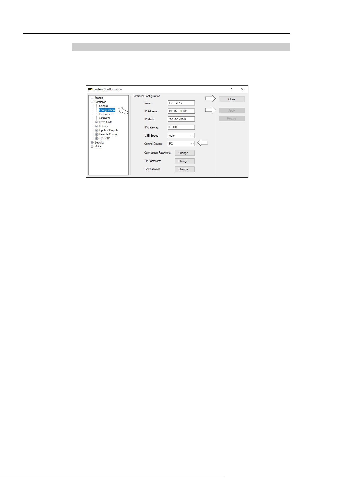
T3-B T6-B Manipulator 6. Operation Mode & LED
88 T-B series Rev.6
6.4.3 Setup from Control Device
Set the control device from EPSON RC+ 7.0.
(1) Select EPSON RC+ 7.0 menu-[Setup]-[System Configuration] to display the [System
Configuration] dialog.
(2)
(5)
(3)
(4)
(2) Select [Controller]-[Configuration].
(3) Select [Control Device] to select the control device from the following two types.
- PC
- Remote (I/O)
(4) Click the <Apply> button.
(5) Click the <Close> button.
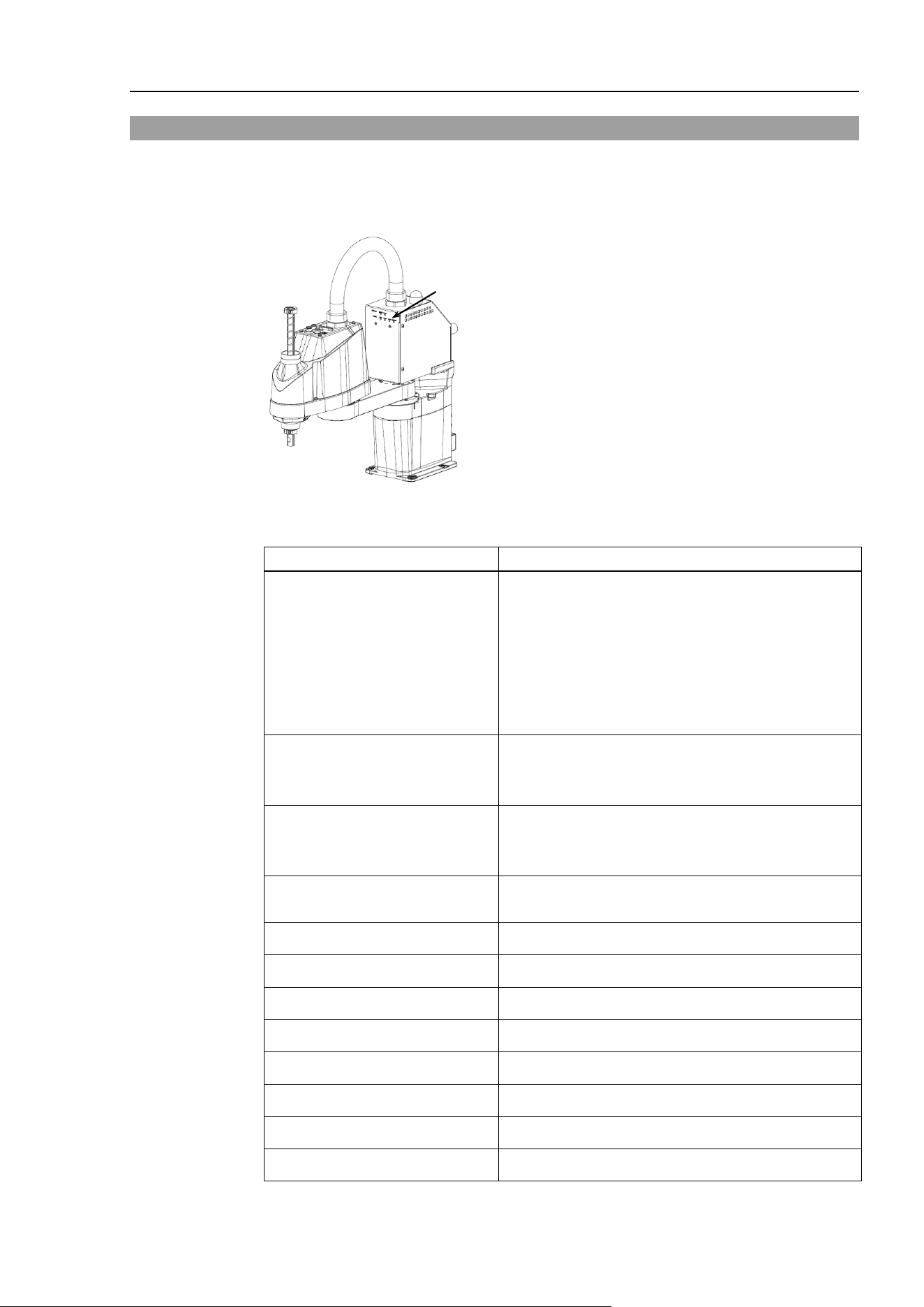
T3-B T6-B Manipulator 6. Operation Mode & LED
T-B series Rev.6 89
6.5 LED
Six LEDs are located on the front panel of the Manipulator.
LEDs (ERROR, E-STOP, TEACH, TEST, AUTO, PROGRAM) turn ON according to the
Controller status (error, Emergency Stop, TEACH mode, Auto mode, Program mode).
LED
(Illustration: T3-B401S)
(Illustration: T3-B401S)
Controller status
LED display
Start up
(Required time is different
depending on the connection
status of the device.)
1. TEST, TEACH, AUTO, and PROGRAM blink (15
seconds)
2. All turn OFF (10 seconds)
3. All turn ON (to 10 seconds )
4. All turn OFF (10-30 seconds )
5. Either of TEACH, AUTO, or PROGRAM turns
ON
Execute Controller status
storage function to the
USB memory
TEACH AUTO, PROGRAM blink.
Complete Controller status
storage to USB memory
TEACH, AUTO, PROGRAM turn ON
(for 2 seconds).
ERROR turns OFF even if an error occurs.
Failure of Controller status
storage to USB memory
ERROR, TEACH, AUTO, PROGRAM turn ON
(for 2 seconds).
Error ERROR turns ON
Warning ERROR blinks.
Emergency Stop
E-STOP turns ON.
TEACH mode TEACH blinks.
Auto mode (AUTO mode) AUTO blinks.
Program mode (AUTO mode) PROGRAM blinks.
AC power supply drop TEACH, AUTO turn ON.
TEST mode TEST blinks.
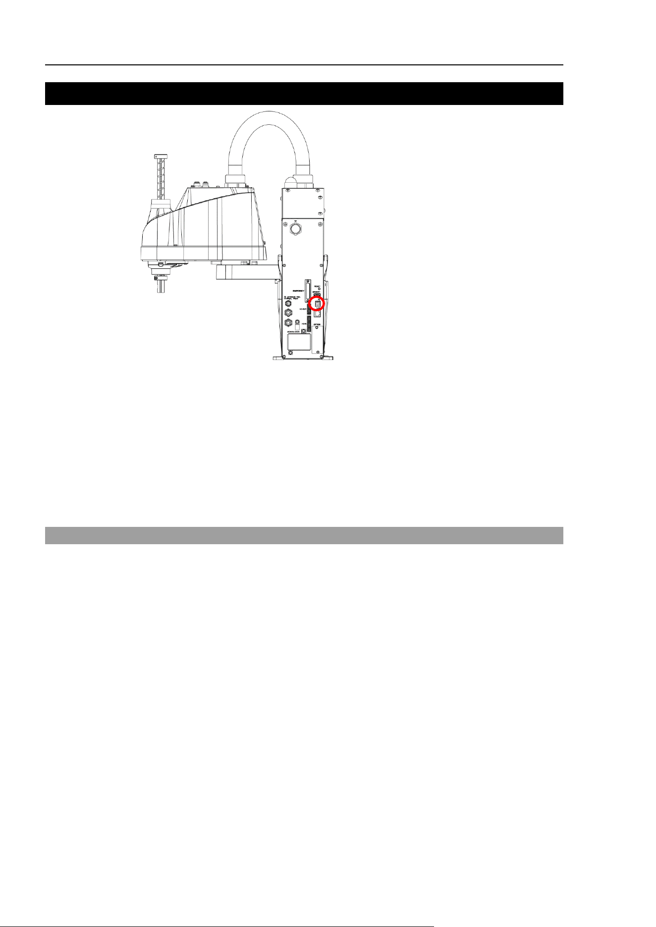
T3-B T6-B Manipulator 7. Development PC Connection Port
90 T-B series Rev.6
7. Development PC Connection Port
Development PC Connection Port
(Illustration: T3-B401S)
- For other details of development PC and Manipulator connection, refer to EPSON RC+
7.0 User’s Guide 5.13.1 PC to Controller Communications Command.
- Be sure to install the EPSON RC+ 7.0 to the development PC first, then connect the
development PC and Manipulator with the USB cable.
If Manipulator and the development PC are connected without installing the EPSON
RC+ 7.0 to the development PC, [Add New Hardware Wizard] appears. If this wizard
appears, click the <Cancel> button.
7.1 What is Development PC Connection Port
The development PC connection port supports the following USB types.
- USB2.0 HighSpeed/FullSpeed (Speed auto selection, or FullSpeed mode)
- USB1.1 FullSpeed
Interface Standard : USB specification Ver.2.0 compliant
(USB Ver.1.1 upward compatible)
Connect the Manipulator and development PC by a USB cable to develop the robot system
or set the Manipulator configuration with the EPSON RC+ 7.0 software installed in the
development PC.
Development PC connection port supports hot plug feature. Cables insert and remove from
the development PC and the Manipulator are available when the power is ON. However,
stop occurs when USB cable is removed from the Manipulator or the development PC
during connection.
NOTE
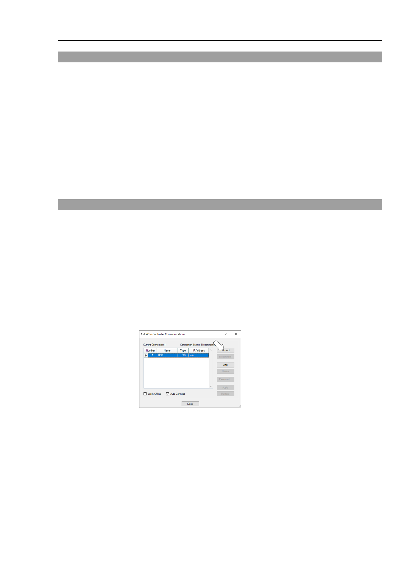
T3-B T6-B Manipulator 7. Development PC Connection Port
T-B series Rev.6 91
7.2 Precaution
When connecting the development PC and the Manipulator, make sure of the following:
- Connect the development PC and the Manipulator with a 5 m or less USB cable.
Do not use the USB hub or extension cable.
- Make sure that no other devices except the development PC are used for development
PC connection port.
- Use a PC and USB cable that supports USB2.0 HighSpeed mode to operate in USB2.0
HighSpeed mode.
- Do not pull or bend the cable strongly.
- Do not allow unnecessary strain on the cable.
- When the development PC and the Manipulator are connected, do not insert or remove
other USB devices from the development PC. Connection with the Manipulator may
be lost.
7.3 Software Setup and Connection Check
Connection of the development PC and the Manipulator is indicated.
(1) Make sure that software EPSON RC+ 7.0 is installed to the Manipulator connected to
the development PC.
(Install the software when it is not installed. Refer to “EPSON RC+ 7.0 User’s Guide”.
(2) Connect the development PC and the Manipulator using a USB cable.
(3) Turn ON the Manipulator.
(4) Start EPSON RC+ 7.0.
(5) Select the EPSON RC+ 7.0 menu-[Setup]-[PC to Controller Communications] to
display the [PC to Controller Communications] dialog.
(6) Select “No.1 USB” and click the <Connect> button.
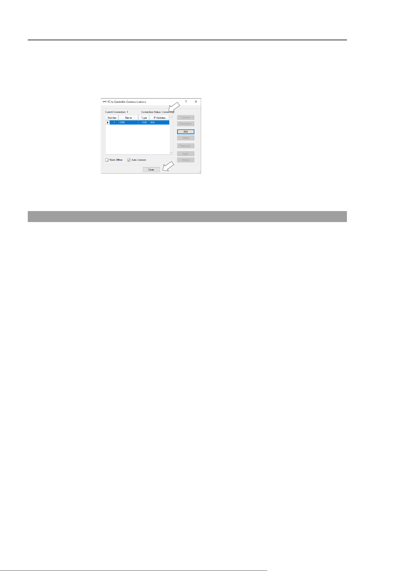
T3-B T6-B Manipulator 7. Development PC Connection Port
92 T-B series Rev.6
(7) After the development PC and the Manipulator connection has completed,
“Connected” is displayed at [Connection status]. Make sure that “Connected” is
displayed and click the <Close> button to close the [PC to Controller
Communications] dialog.
The connection between the development PC and the Manipulator is completed. Now the
robot system can be used from EPSON RC+ 7.0.
7.4 Disconnection of Development PC and Manipulator
Disconnection of the development PC and the Manipulator communication.
(1) Select the EPSON RC+ 7.0 menu-[Setup]-[PC to Controller Communications] to
display the [PC to Controller Communications] dialog.
(2) Click the <Disconnect> button.
Communication between the Manipulator and the development PC is disconnected and
the USB cable can be removed.
If the USB cable is removed when the Manipulator and the development PC are connected,
the Manipulator will stop. Be sure to click the <Disconnect> button in the [PC to Controller
Communications] dialog before USB cable is removed.
NOTE
T3-B T6-B Manipulator 8. Memory Port
T-B series Rev.6 93
8. Memory Port
Connect a commercial USB memory to the Manipulator memory port to use the Controller
status storage function to the USB memory.
8.1 What is Controller Status Storage Function?
This function saves various kinds of Manipulator data to the USB memory. Data saved in
USB memory is loaded to EPSON RC+ 7.0 to get the status of the Manipulator and the
program simply and accurately.
The saved data can also be used for restoring the Manipulator.
Unable to execute status storage to USB memory when operating the Manipulator.
8.2 Before Using Controller Status Storage Function
8.2.1 Precautions
CAUTION
■
Controller status storage function is available at any time and in any Manipulator
status after starting the Manipulator.
However, operations form the console including stop and pau
se are not available
while executing this function.
Also,
this function influences the Manipulator cycle time and the communication
with EPSON RC+ 7.0. Other than only when it is necessary, do not execute this
function when operating the Manipulator.
- Make sure that the USB port is used only for USB memory even though the port on the
Manipulator is a universal USB port.
- Insert the USB memory directly into the Manipulator memory port. Connection with
cables or hubs between the Manipulator and the USB memory is not assured.
- Make sure that the USB memory is inserted or removed slowly.
- Do not edit the saved files with an editor. Operation of the robot system after data
restoration to the Manipulator is not assured.
8.2.2 Adoptable USB Memory
Use USB memory that meets following conditions.
- USB2.0 supported
- Without security function
USB memory with password input function cannot be used.
- No installation of a driver or software is necessary for Windows 8, Windows 10, or
Windows 11, Linux.
(For supported operating systems for the EPSON RC+ 7.0, refer to “2.4 System
Example”.)
T3-B T6-B Manipulator 8. Memory Port
94 T-B series Rev.6
8.3 Controller Status Storage Function
8.3.1 Controller Status Storage
CAUTION
■
Controller status storage function is available at any time and in any Manipulator
status
after starting the Manipulator.
However, operations form the console including stop and pause are not available
while executing this function.
Also, this function influences the Manipulator cycle time and the communication
with EPSON RC+ 7.0. Other than on
ly when it is necessary, do not execute this
function when operating the Manipulator.
Use this procedure to save the status of the Manipulator to USB memory.
(1) Insert the USB memory into the memory port.
When the data transfer starts, the LED of TEACH, AUTO, and PROGRAM starts
blinking. Wait until the LED status changes.
(The data transfer time varies according to the data size such as of the projects.)
(2) When the Manipulator status storage is completed successfully, the LED of TEACH,
AUTO, and PROGRAM are turned ON for two seconds. Note that the LED of ERROR
turns OFF even in the error status.
If it ends in failure, the LED of ERROR, TEACH, AUTO, and PROGRAM are turned
ON for two seconds.
(3) Remove the USB memory from the Manipulator.
- USB memory with LED is recommended to check the status changes.
- When storage is executed during Motor ON status, it may fail to store the status. Use
another USB memory or execute the storage during Motor OFF status.
NOTE
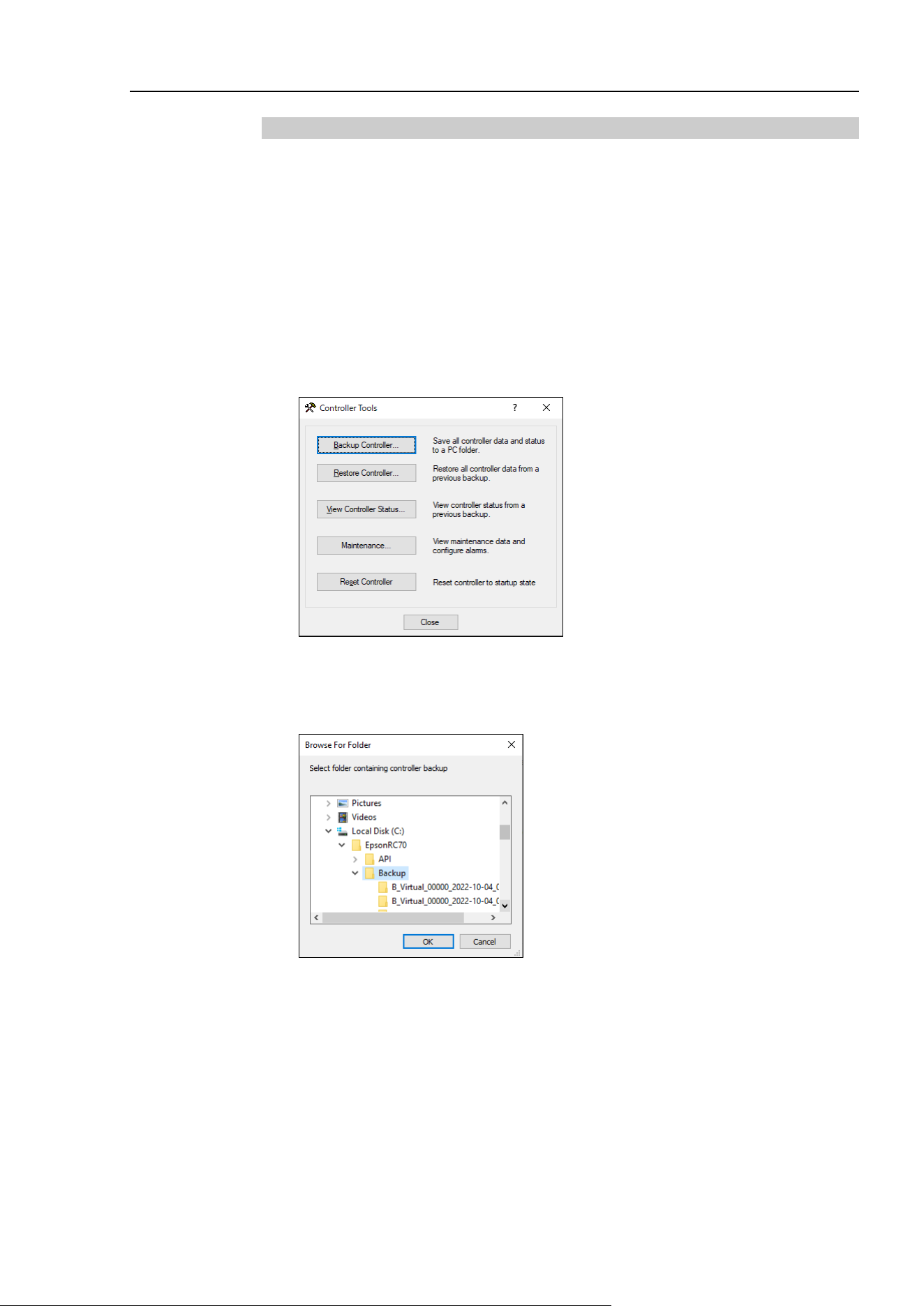
T3-B T6-B Manipulator 8. Memory Port
T-B series Rev.6 95
8.3.2 Load Data with EPSON RC+ 7.0
The following shows the procedure to load the data stored in the USB memory by EPSON
RC+ 7.0 and display the Controller status.
(1) Insert the USB memory into the PC with EPSON RC+ 7.0.
(2) Make sure that the following folder is indicated in the USB memory.
BU_T_serial number_data status was saved
→ Example:BU_T_12345_2013-10-29_092951
(3) Copy the folder confirmed in procedure (2) to the “\EpsonRC70\Backup” folder.
(4) Select the EPSON RC+ 7.0 menu-[Tools]-[Controller] to display the [Controller Tools]
dialog.
(5) Click the <View Controller Status…> button.
(6) [Browse For Folder] dialog appears. Select the folder copied in procedure (3) and click
the <OK> button.
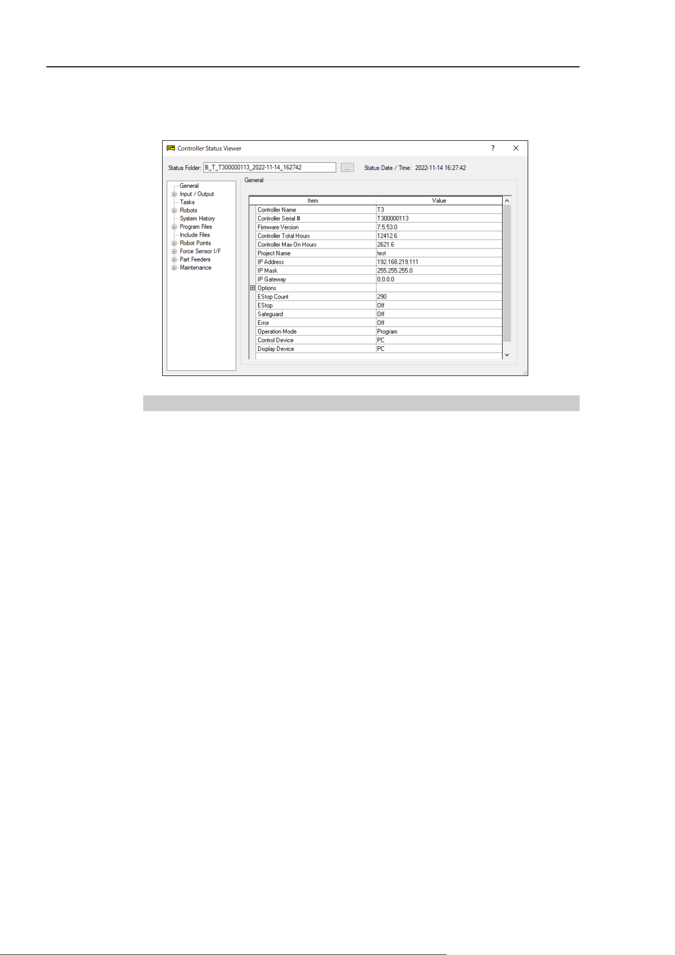
T3-B T6-B Manipulator 8. Memory Port
96 T-B series Rev.6
(7) [Controller Status Viewer] dialog appears to confirm the Controller status.
For details, refer to View Controller Status in EPSON RC+ 7.0 User’s Guide 5.12.8
Controller Command (Tools Menu).
8.3.3 Transfer with E-mail
Follow this procedure to transfer the data by e-mail that was saved to the USB memory.
(1) Insert the USB memory to a PC that supports sending of e-mail.
(2) Make sure that the USB memory has following folders.
BU_T_serial number_data status was saved
→ Example:BU_T_12345_2013-10-29_092951
(3) Send all the folders by e-mail.
Delete files that do not relate to the project before transfer.
This function is used to send the data to the system director and EPSON from the end users
for problem analysis.
NOTE

T3-B T6-B Manipulator 8. Memory Port
T-B series Rev.6 97
8.4 Details of Data
The following data files are created by the Controller status storage function.
File Name
Outline
Backup.txt Information file
for restore
File with information for Manipulator restore.
CurrentMnp01.PRM Robot parameter Saves information such as ToolSet.
CurrentStatus.txt
Save status
Saves program and I/O status.
ErrorHistory.csv
Error history
InitFileSrc.txt
Initial setting
Saves various settings of the Controller.
MCSys01.MCD Robot setting Saves information of connected Manipulator.
SrcmcStat.txt Hardware
information
Saves installation information of hardware.
ProjectName.obj OBJ file Result of project build.
Prg file is not included.
GlobalPreserves.dat Global Preserve
variables
Saves values of Global Preserve variables.
WorkQueues.dat WorkQue
information
Saves information of Queues information of the WorkQue.
MCSRAM.bin
MCSYSTEMIO.bin
MCTABLE.bin
MDATA.bin
SERVOSRAM.bin
VXDWORK.bin
Inner information
of Manipulator
All files related to
project except
ProjectName.obj *1
Project When [Include project files when status exported] check box
is checked in EPSON RC+ 7.0 menu-[Setup]-
[System Configuration]-[Controller]-
[Preference], the project file is stored.
Includes program files.
*1 Storage of “All files related to project except ProjectName.obj” can be specified by a setting.

T3-B T6-B Manipulator 9. LAN (Ethernet Communication) Port
98 T-B series Rev.6
9. LAN (Ethernet Communication) Port
- Refer to EPSON RC+ 7.0 User’s Guide 5.13.1 [PC to Controller Communications]
Command (Setup Menu)
for other details for the development PC and Manipulator
connection.
- For Ethernet (TCP/IP) communication with robot application software, refer to EPSON
RC+ 7.0 Online Help or User’s Guide 14. TCP/IP Communications.
9.1 What is the LAN (Ethernet Communication) Port
Ethernet communication port supports 100BASE-TX / 10 BASE-T.
This port is used for two different purposes.
Connection with development PC
LAN (Ethernet communication) port is used for connection of the Manipulator and the
development PC.
Equivalent operation is available to connect between the Manipulator and the
development PC with the development PC connection port.
(Reference: 7. Development PC Connection Port)
Connection with other Manipulator, Controller, or PC
The LAN (Ethernet communication) port can be used as an Ethernet (TCP/IP)
communication port to communicate between multiple controllers from robot
application software.
9.2 IP Address
From the following firmware version password authentication is required when connecting
Controllers and PCs to a global accessible network.
F/W : Ver.7.4.58.x
For details of setting password, refer to “EPSON RC+ 7.0 User's Guide 1.9.1 Setting
Password for PC Ethernet Controller Connection”.
Our robot system is provided on the assumption that customers use it in the closed local area
networks. We considered the setting of the global IP address is access to the Internet and
changed the specification to perform password authentication in order to secure the
connections.
Password authentication is not performed in case of USB connections.
Be sure to use the following private IP addresses.
Private Address List
10.0.0.1
to
10.255.255.254
172.16.0.1
to
172.31.255.254
192.168.0.1
to
192.168.255.254
The following is the configuration of the controller Manipulator at delivery.
IP Address : 192.168.0.1
IP Mask : 255.255.255.0
IP Gateway : 0.0.0.0
NOTE
NOTE
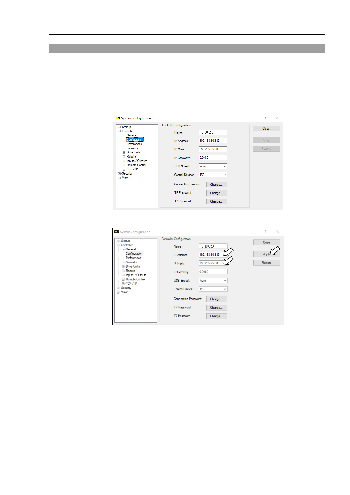
T3-B T6-B Manipulator 9. LAN (Ethernet Communication) Port
T-B series Rev.6 99
9.3 Changing Manipulator IP Address
In this section, the procedure to change the Manipulator IP address when connecting
Manipulator development PC connection port and the development PC by the USB cable is
indicated.
(1) For connection between the development PC and the Manipulator.
Reference: 7. Development PC Connection Port
(2) Select the EPSON RC+ 7.0 menu-[Setup]-[Controller] to display the following dialog.
(3) Select [Controller]-[Configuration].
(4) Enter the proper IP address and subnet mask and click the <Apply> button.
(5) Click the <Close> button. The Manipulator reboots automatically.
IP address configuration is completed and the Manipulator reboot dialog disappears.
When the Manipulator and the development PC are connected via the Ethernet, the
Manipulator IP address can also be changed. However, Manipulator and the development
PC do not connect automatically after rebooting the Manipulator at Ethernet connection.
NOTE
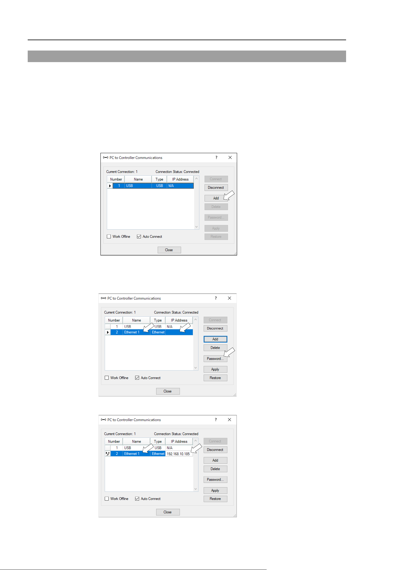
T3-B T6-B Manipulator 9. LAN (Ethernet Communication) Port
100 T-B series Rev.6
9.4 Connection of Development PC and Manipulator with Ethernet
Connection between the development PC and the Manipulator is shown below.
(1) Connect the development PC and the Manipulator using the Ethernet cable.
(2) Turn on the Manipulator.
(3) Start EPSON RC+ 7.0.
(4) Display the [PC to Controller Communication] dialog from [Setup] in EPSON RC+ 7.0
menu.
(5) Click the <Add> button.
(6) Connection “No.2” is added. Set the following and click the <Apply> button.
Name : Valid value to identify the Manipulator to connect
IP Address : IP address for Manipulator to connect
(7) [Name] and [IP Address] specified in procedure (6) is displayed.
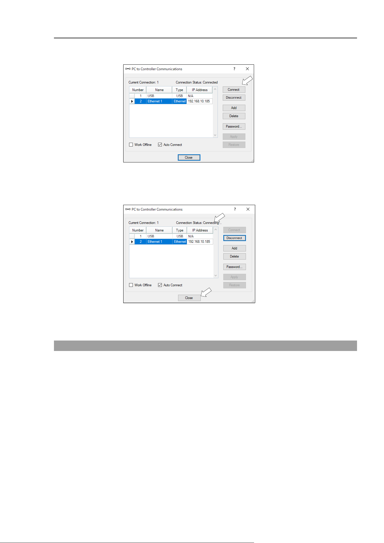
T3-B T6-B Manipulator 9. LAN (Ethernet Communication) Port
T-B series Rev.6 101
(8) Make sure that “No.2” is selected, and click the <Connect> button.
(9) After the development PC and Manipulator connection is completed, “Connected” is
displayed in the [Connection status:]. Make sure that “Connected” is displayed and click
the <Close> button to close the [PC to Controller Communications] dialog.
Connection between the development PC and the Manipulator is complete. Now the robot
system can be used via an Ethernet connection from EPSON RC+ 7.0.
9.5 Disconnection of Development PC and Manipulator with Ethernet
Disconnection of the development PC and the Manipulator is shown below.
(1) Display [PC-Controller Connection] dialog from [Setup] in EPSON RC+ 7.0 menu.
(2) Click the <Disconnect> button.
Communication between the Manipulator and the development PC is disconnected and
the Ethernet cable can be removed.
If the Ethernet cable is removed when the Manipulator and the development PC is connected,
Emergency Stop occurs and the Manipulator stops. Be sure to click the <Disconnect> button
in the [PC to Controller Communications] dialog before the Ethernet cable is removed.
NOTE

T3-B T6-B Manipulator 10. TP Port
102 T-B series Rev.6
10. TP Port
10.1 What is the TP Port?
The TP port connects the Teach Pendant to the manipulator. You can connect the Teach
Pendant (TP2, TP3).
Dedicated convert cable* is necessary if connecting TP2 to T-B series manipulator. Contact
the supplier of your region if only convert cable is necessary.
* TP Exchange Cable: R12NZ900L6
When nothing is connected to the TP port, Emergency Stop status occurs in the Manipulator.
When the Teach Pendant is not connected, connect the TP bypass plug.
Store the removed TP in place so that it can be distinguished from the TP connected to the
controller.
Do not connect the devices except TP2, TP3 to the TP port. Connecting these devices may
result in malfunction of the device since the pin assignments are different.
External enable switch cannot be connected to the TP port. Use the enable switch provided
with the TP.
10.2 Teach Pendant Connection
A dedicated cable is attached to the Teach Pendant. Connect this cable connector to the TP
port.
Communication is set automatically. Enable the Teach Pendant by one of the following
procedures.
- Insert the Teach Pendant connector to the Manipulator and turn ON the Manipulator.
- Insert the Teach Pendant connector while the Manipulator is turned ON.
Teach Pendant connection and disconnection from the Controller are allowed when the
Manipulator power is ON.
When the Teach Pendant connector is removed from the Manipulator with the mode selector
key switch of the Teach Pendant in the “Teach” position, the operation mode will remain in
the TEACH mode. The operation mode cannot be switched to AUTO mode. Be sure to
remove the Teach Pendant after switching the operation mode to “Auto” mode.
The administrator supervises the removal and storage of the Teach Pendant. Only the
personnel who is allowed can touch it. Store it so that you can see the Teach Pendant is not
connected to the controller.
For details, refer to manual
Robot Contoroller Option Teach Pendant TP2.
Robot Contoroller Option Teach Pendant TP3.
NOTE
NOTE
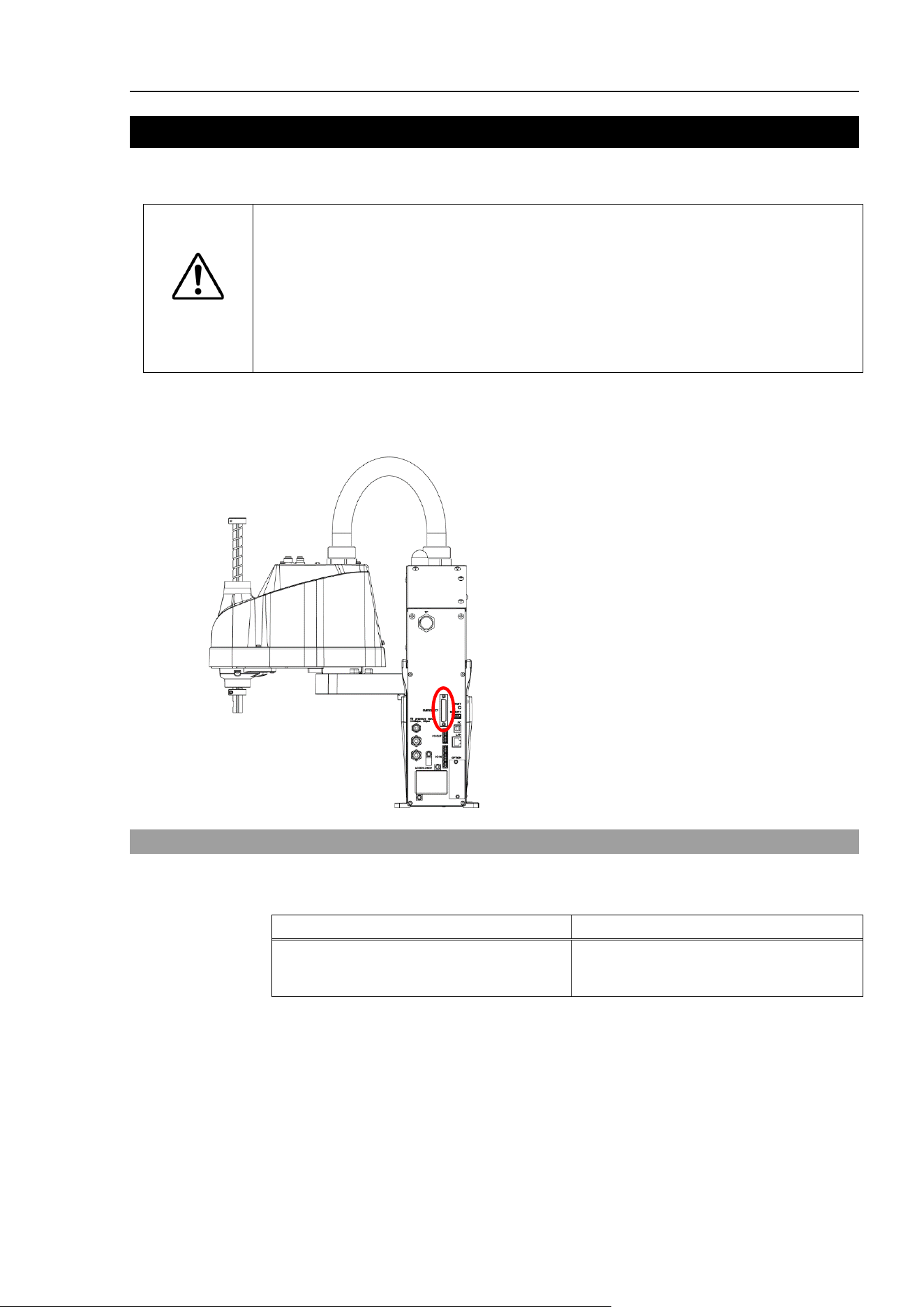
T3-B T6-B Manipulator 11. EMERGENCY
T-B series Rev.6 103
11. EMERGENCY
The details of safety requirements for this section are described in EPSON RC+ 7.0 User’s
Guide 2. Safety. Please refer to them to keep the robot system safe.
WARNING
Make sure that emergency stop or safeguard operate properly before operating,
not only
booting but also usage changed such as options added or parts
replaced as maintenance.
Before connecting the connector, make sure that the pins are not bent.
Connecting with the pins bent may damage the connector and result in
malfunction of the robot system.
Connect a safeguard switch or Emergency Stop switch to the EMERGENCY connector for
safety.
When nothing is connected to the EMERGENCY connector, the robot system does not
operate normally.
EMERGENCY Connector
(Illustration: T3-B401S)
11.1 Safeguard Switch and Latch Release Switch
The EMERGENCY connector has input terminals for the Safeguard switch and the
Emergency Stop switch. Be sure to use these input terminals to keep the system safe.
Connector
Standard
EMERGENCY connector
(Manipulator side)
D-Sub 25 pin female (cable side)
D-Sub 25 pin male (board side)
* The E-STOP BOX, EMERGENCY connector cable, terminal block, and
EMERGENCY connector kit are offered as options.
NOTE
T3-B T6-B Manipulator 11. EMERGENCY
104 T-B series Rev.6
11.1.1 Safeguard Switch
WARNING
The interlock of the Safeguard must be functioning when the robot system is
operated. Do not operate the system under the condition that the switch cannot
be turned ON/OFF (e.g. The tape is put around the switch.). Operating the robot
system when the switch is not functioning properly is extremely hazardous and
may cause serious safety problems as the Safeguard input cannot fulfill its
intended function.
In order to maintain a safe working zone, a safeguard must be erected around the
Manipulator. The safeguard must have an interlock switch at the entrance to the working
zone. The Safeguard that is described in this manual is one of the safeguards and an interlock
of the Safeguard is called a Safeguard switch. Connect the Safeguard switch to the Safeguard
input terminal on the EMERGENCY connector.
The Safeguard switch has safety features such as temporary hold-up of the program or the
operation-prohibited status that are activated whenever the Safeguard is opened.
Observe the following in designing the Safeguard switch and the Safeguard.
- For the Safeguard switch, select a switch that opens as the Safeguard opens, and not by the
spring of the switch itself.
- The signal from the Safeguard (Safeguard input) is designed to input to two redundant
signals. If the signals at the two inputs differ by two seconds or more, the system recognizes
it to be a critical error. Therefore, make sure that the Safeguard switch has two separate
redundant circuits and that each connects to the specified pins at the EMERGENCY
connector on the Manipulator.
- Make sure to design the safeguard to prevent the door from closing accidentally.
11.1.2 Latch Release Switch
The controller software latches these conditions:
- The safeguard is open.
- The operation mode is set to “TEACH”.
The EMERGENCY connector has an input terminal for a latch release switch that cancels
the latched conditions.
Open : The latch release switch latches conditions that the safeguard is open or the
operation mode is “TEACH”.
Closed : The latch release switch releases the latched conditions.
When the latched TEACH mode is released while the safeguard is open, the status of
Manipulator power is operation-prohibited because the safeguard is open at that time.
To execute a Manipulator operation, close the safeguard again, and then close the latch
release input.
NOTE

T3-B T6-B Manipulator 11. EMERGENCY
T-B series Rev.6 105
11.1.3 Checking Latch Release Switch Operation
After connecting the safeguard switch and latch release switch to the EMERGENCY
connector, be sure to check the switch operation for safety by following the procedures
described below before operating the Manipulator.
(1) Turn ON the Manipulator while the safeguard is open in order to boot the controller
software.
(2) Make sure that “Safety” is displayed on the main window status bar.
(3) Close the safeguard, and turn ON the switch connecting to the latch release input.
Make sure that the “Safety” is dimmed on the status bar.
The information that the safeguard is open can be latched by software based on the latch
release input condition. To cancel the condition, close the safeguard, and then close the
safeguard latch release input.
Open : The latch release switch latches the condition that the safeguard is open.
Closed : The latch release switch does not latch the condition that the safeguard is open.
The latch release input also functions to acknowledge the change of to TEACH mode.
In order to change the latched condition of TEACH mode, turn the mode selector key switch
on the Teach Pendant to “Auto”. Then, close the latch release input.
11.2 Emergency Stop Switch Connection
11.2.1 Emergency Stop Switch
If it is desired to add an external Emergency Stop switch(es) in addition to the Emergency
Stop on the Teach Pendant and Operator Panel, be sure to connect such Emergency Stop
switch(es) to the Emergency Stop input terminal on the EMERGENCY connector.
The Emergency Stop switch connected must comply with the following and related safety
standard (IEC60947-5-5, etc.):
- It must be a push button switch that is “normally closed”.
- A button that does not automatically return or resume.
- The button must be mushroom-shaped and red.
- The button must have a double contact that is “normally closed”.
The signal from the Emergency Stop switch is designed to use two redundant circuits.
If the signals at the two circuits differ by two seconds or more, the system recognizes it as
a critical error. Therefore, make sure that the Emergency Stop switch has double contacts
and that each circuit connects to the specified pins on the EMERGENCY connector at the
Manipulator. Refer to “11.4 Circuit Diagrams”.
Give the emergency stop function to all the equipment which have executable token.
NOTE
NOTE

T3-B T6-B Manipulator 11. EMERGENCY
106 T-B series Rev.6
11.2.2 Checking Emergency Stop Switch Operation
Once the Emergency Stop switch is connected to the EMERGENCY connector, continue
the following procedure to make sure that the switch functions properly. For the safety of
the operator, the Manipulator must not be powered ON until the following test is
completed.
(1) Turn ON the Manipulator to boot the controller software while pressing the Emergency
Stop switch.
(2) Make sure that E-STOP LED of the Manipulator is lighting.
(3) Make sure that “E.Stop” is displayed on the status bar on the main window.
(4) Release the Emergency Stop Switch.
(5) Execute the RESET command.
(6) Make sure that E-STOP LED is turned OFF and that “E-Stop” is dimmed on the main
window status bar.
11.2.3 Recovery from Emergency Stop
To recover from the emergency stop condition, follow the procedure of safety check as
required by the system.
After safety check, the operations below are required to recover from the emergency stop
condition.
- Release the Emergency Stop Switch
- Execute the RESET command
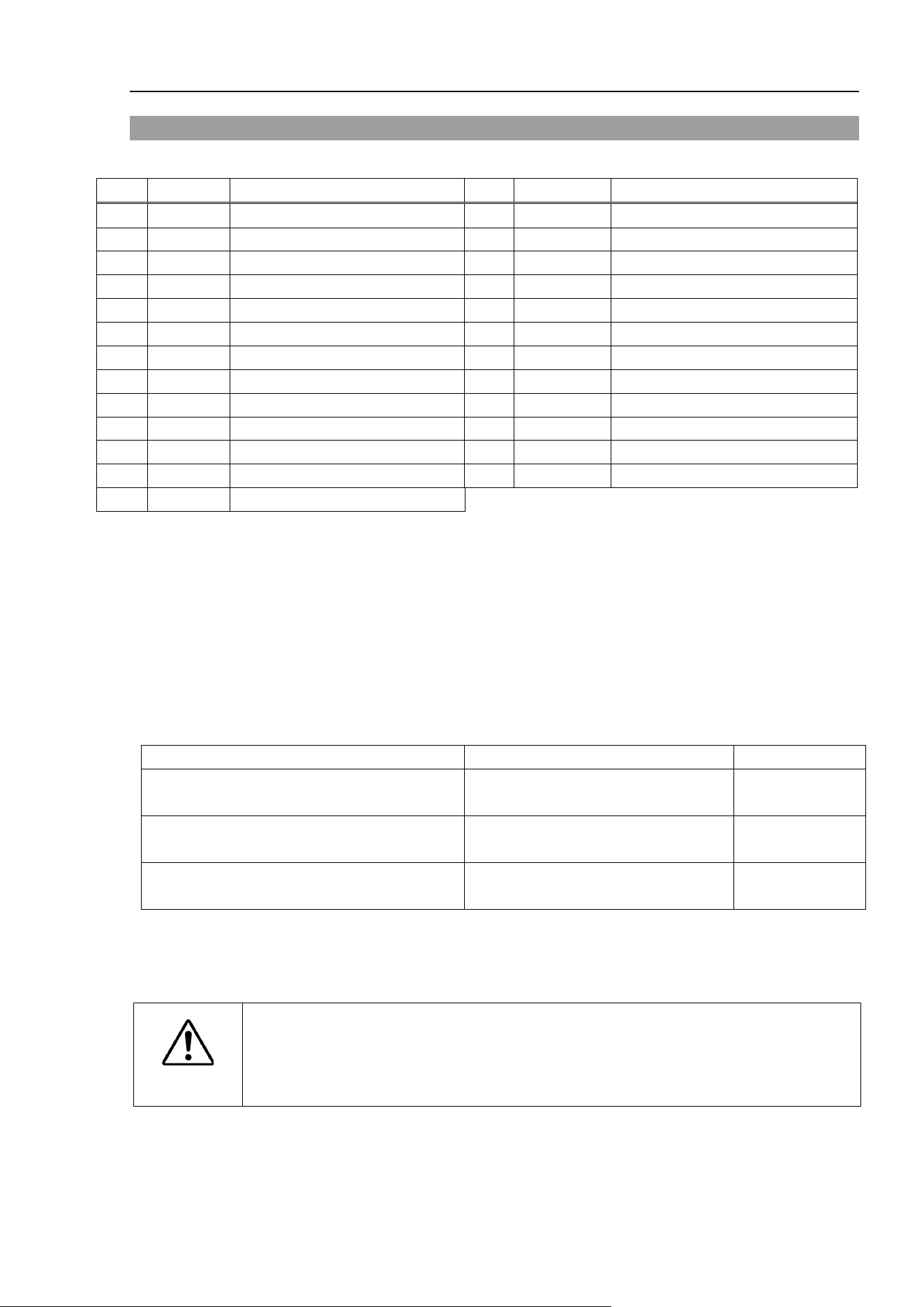
T3-B T6-B Manipulator 11. EMERGENCY
T-B series Rev.6 107
11.3 Pin Assignments
The EMERGENCY connector pin assignments are as follows: (D-Sub 25 pin male)
Pin No.
Signal
Function
Pin No.
Signal
Function
1
ESW11
Emergency Stop switch contact (1)
*3
14
ESW21
Emergency Stop switch contact (2)
*3
2
ESW12
Emergency Stop switch contact (1)
*3
15
ESW22
Emergency Stop switch contact (2)
*3
3
ESTOP1+
Emergency Stop circuit 1 (+)
*4
16
ESTOP2+
Emergency Stop circuit 2 (+)
*4
4
ESTOP1-
Emergency Stop circuit 1 (-)
*4
17
ESTOP2-
Emergency Stop circuit 2 (-)
*4
5
Not Used
*1
18
SDLATCH1
Safeguard Latch Release
6
Not Used
*1
19
SDLATCH2
Safeguard Latch Release
7
SD11
Safeguard input (1)
*2
20
SD21
Safeguard input (2)
*2
8
SD12
Safeguard input (1)
*2
21
SD22
Safeguard input (2)
*2
9
24V
+24V output
22
24V
+24V output
10
24V
+24V output
23
24V
+24V output
11
24VGND
+24V GND output
24
24VGND
+24V GND output
12
24VGND
+24V GND output
25
24VGND
+24V GND output
13
Not Used
*1
*1 Do not connect anything to these pins.
*2 A critical error occurs if the input values from the Safeguard 1 and Safeguard 2 are
different for two or more seconds. They must be connected to the same switch with
two sets of contacts.
*3 A critical error occurs if the input values from the Emergency Stop switch contact 1
and Emergency Stop switch contact 2 are different for two or more seconds. They must
be connected the same switch with two sets of contacts.
*4 Do not apply reverse voltage to the Emergency Stop circuit.
Emergency Stop switch output rated load
+30 V 0.3 A or under
1-2, 14-15 pin
Emergency Stop rated input voltage range
Emergency Stop rated input current
+24 V ±10%
37.5 mA ±10% /+24 V input
3-4, 16-17 pin
Safeguard rated input voltage range
Safeguard rated input current
+24 V ±10%
10 mA/+24 V input
7-8, 20-21 pin
Latch Release rated input voltage range
Latch Release rated input current
+24 V ±10%
10 mA/+24 V input
18-19 pin
The total electrical resistance of the Emergency Stop switches and their circuit should be 1
Ω or less.
CAUTION
■
The 24 V output is for emergency stop. Do not use it for other purposes. Doing so
may result in system malfunction.
■
Do not apply reverse voltage to the Emergency Stop
circuit. Doing so may result
in system malfunction.
NOTE
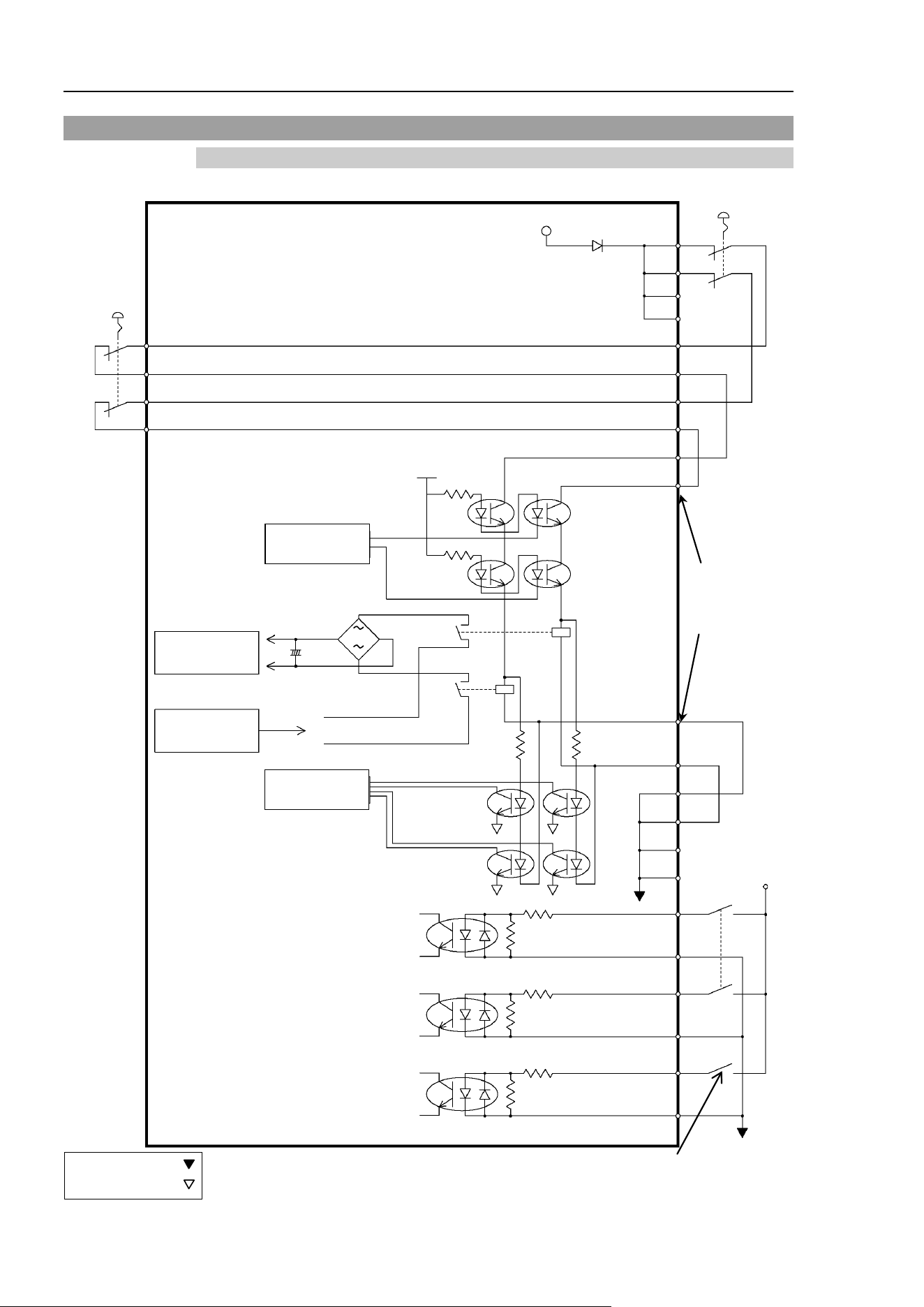
T3-B T6-B Manipulator 11. EMERGENCY
108 T-B series Rev.6
11.4 Circuit Diagrams
11.4.1 Example 1: External emergency stop switch typical application
+24V
+5V
Safety Door input 1
External
+24V
Safety Door input 2
Latch release input
Latch release input Close :Latch off
Open :Latch on
Main Circuit
Control
AC Input
Emergency
Stop switch of
an Operation
Unit (TP)
External +24V
GND
External Emergency
Stop switches
Motor Driver
+
−
Manipulator
9
10
22
23
1
2
14
15
3
16
4
17
11
12
24
25
7
8
20
21
18
19
+
Emergency
Stop detection
NOTE:+24V GND
+ 5V GND
ESTOP1+
ESTOP2+
ESTOP1
−
ESTOP2−
Be careful of
the direction
of voltage
application
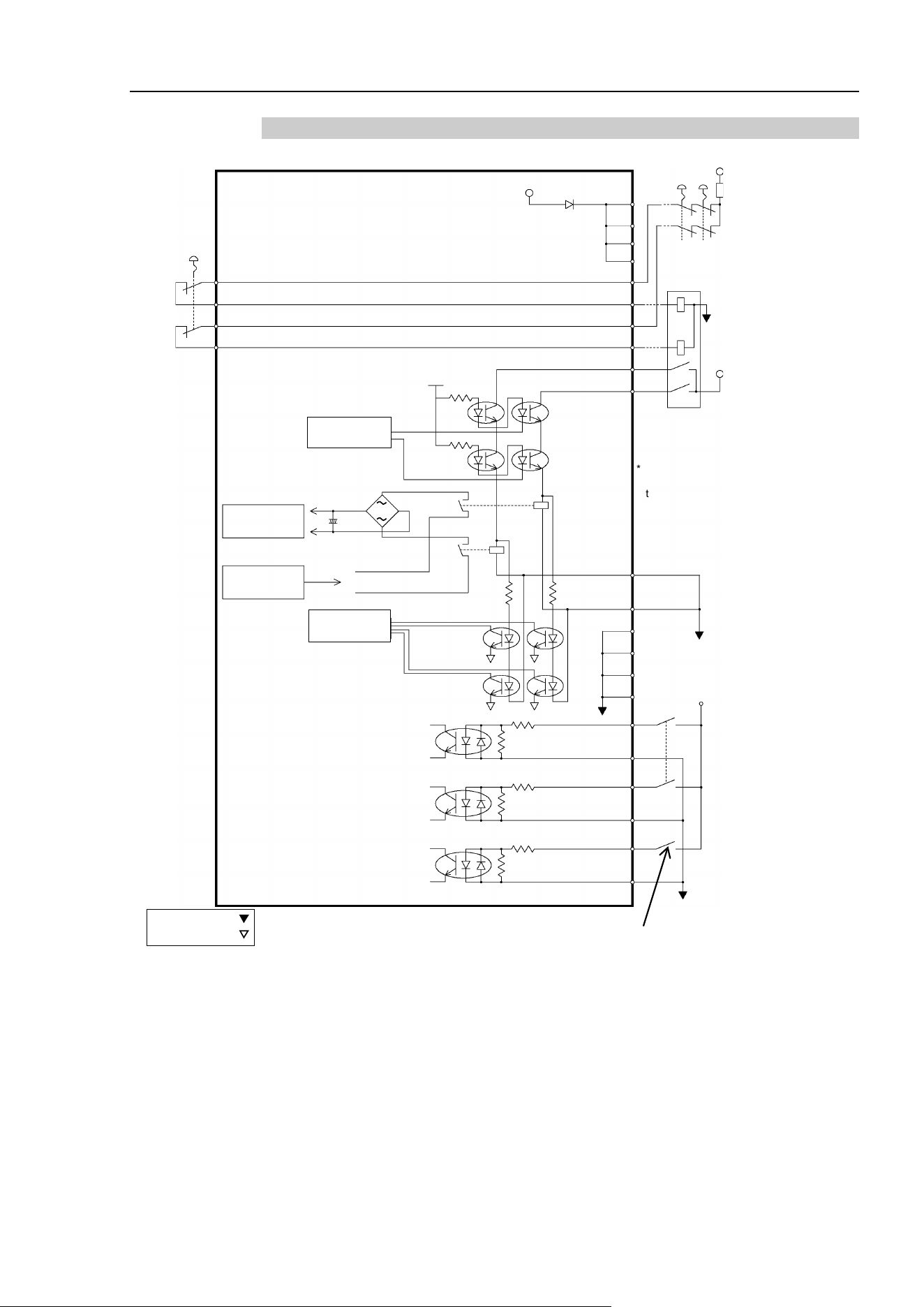
T3-B T6-B Manipulator 11. EMERGENCY
T-B series Rev.6 109
11.4.2 Example 2: External safety relay typical application
* For the protection of the
emergency stop circuit,
the fuse’s capacity
should be as follows:
- Meets the capacity of
the external safety
relay
- 0.4A or less
External safety relay
(The above diagram
is simplified for
representation.)
External
+24V
GND
+24V
+5V
Safety Door input 1
Safety Door input 2
Latch Release input
AC Input
Motor Driver
External +24V
Fuse
+ −
External
+24V
Manipulator
09
10
22
23
1
2
14
15
3
16
4
17
11
12
24
25
7
8
20
21
18
19
+
Main Circuit
Control
Emergency
Stop switch of
an Operation
Unit (TP)
Emergency
Stop detection
External
+24V
Latch release input Close :Latch off
Open :Latch on
External
+24V
GND
NOTE:+24V GND
+ 5V GND
External
+24V GND
T3-B T6-B Manipulator 12. Standard I/O Connector
110 T-B series Rev.6
12. Standard I/O Connector
CAUTION
Be careful not to exceed rated current range or rated current which are defined
in manual.
If exceeding rated current, the Manipulator may now operate at worst.
Standard I/O Connector is a connector mounted on back side of the Manipulator for
connecting your input/output equipment to the system.
Connector name
Pins
Bit number
I/O (Input) Connector
18
0-17
I/O (Output) Connector
12
0-11
For cable wiring, refer to “3.7.2 Noise Countermeasures” in order to prevent noise.
Remote function is initially assigned to both input and output from 0 to 8. For further details,
refer to “14. I/O Remote Settings”.
Also, for details of hand I/O, refer to “13.Hand I/O Connector”.
12.1 Input Circuit
Input Voltage Range : +12 to 24 V ±10%
ON Voltage : +10.8 V (min.)
OFF Voltage : +5 V (max.)
Input Current : 10 mA (TYP) at +24 V input
Two types of wiring are available for use with the two-way photo coupler in the input circuit.
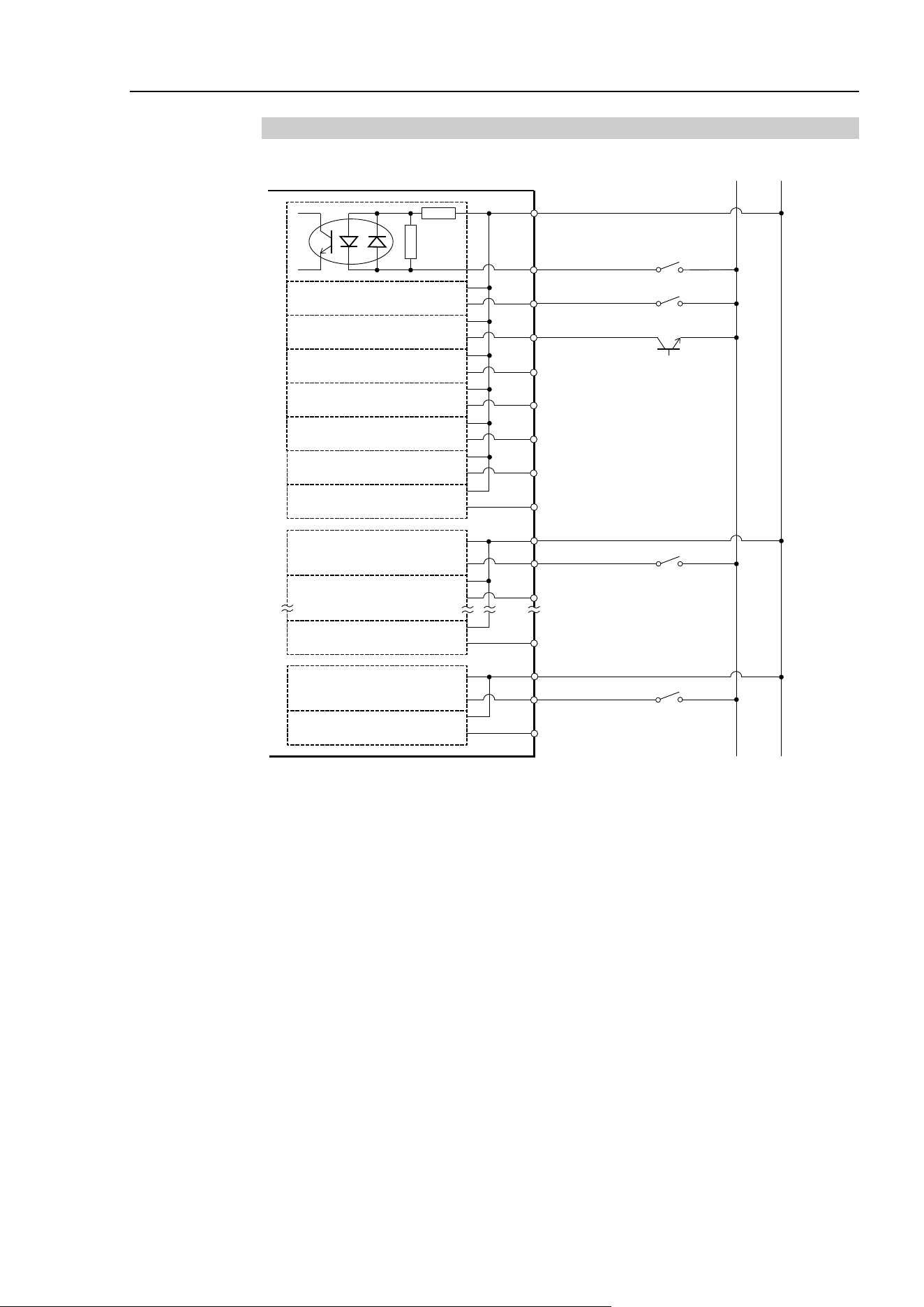
T3-B T6-B Manipulator 12. Standard I/O Connector
T-B series Rev.6 111
12.1.1 Typical Input Circuit Application 1
(Same as above)
Omit
5 Input No.0 to 7 common
1 Input No.0
15 Input No.1
2 Input No.2
16 Input No.3
3 Input No.4
17 Input No.5
4 Input No.6
18 Input No.7
GND +DC
19 Input No.8 to 15 common
6 Input No.8
20 Input No.9
Standard I/O (input) connector
14 Input No.16 to 17
common
10 Input No.16
24 Input No.17
23 Input No.15
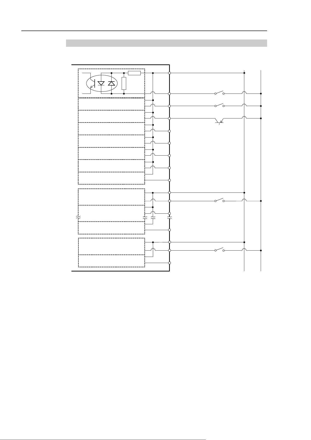
T3-B T6-B Manipulator 12. Standard I/O Connector
112 T-B series Rev.6
12.1.2 Typical Input Circuit Application 2
(Same as above)
Omit
5 Input No.0 to 7 common
1 Input No.0
15 Input No.1
2 Input No.2
16 Input No.3
3 Input No.4
17 Input No.5
4 Input No.6
18 Input No.7
GND +DC
19 Input No.8 to 15 common
6 Input No.8
20 Input No.9
Standard I/O (input) connector
14 Input No.16 to 17 common
10 Input No.16
24 Input No.17
23 Input No.15
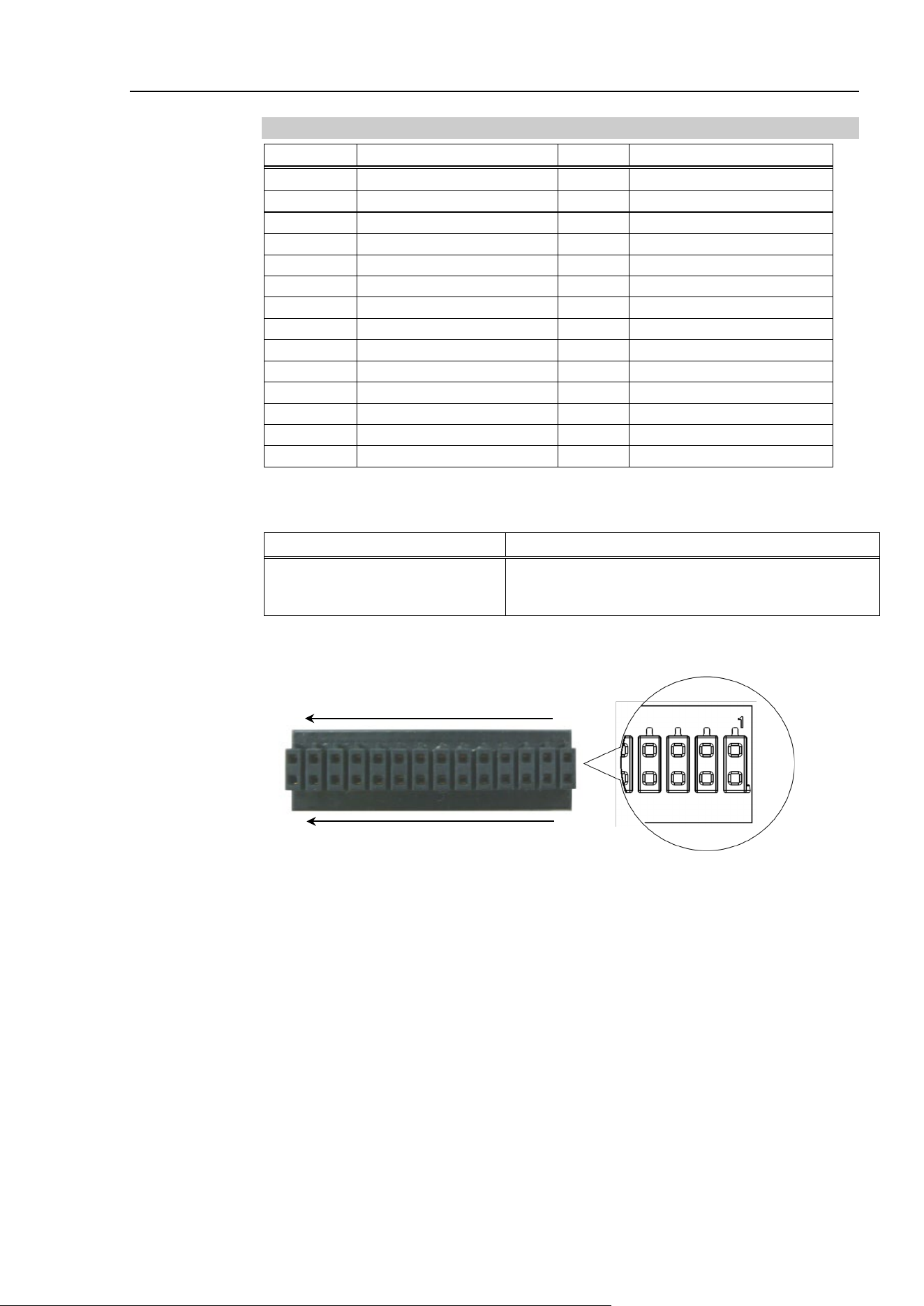
T3-B T6-B Manipulator 12. Standard I/O Connector
T-B series Rev.6 113
12.1.3 Pin Assignments of Input Circuit
Pin No.
Signal Name
Pin No.
Signal Name
1
Input No. 0 (Start)
15
Input No. 1 (SelProg1)
2
Input No. 2 (SelProg2)
16
Input No. 3 (SelProg4)
3
Input No. 4 (Stop)
17
Input No. 5 (Pause)
4
Input No. 6 (Continue)
18
Input No. 7 (Reset)
5
Input common No. 0 to 7
19
Input common No. 8 to 15
6
Input No. 8
20
Input No. 9
7
Input No. 10
21
Input No. 11
8
Input No. 12
22
Input No. 13
9
Input No. 14
23
Input No. 15
10
Input No. 16
24
Input No. 17
11
Not Used
25
Not Used
12
Not Used
26
Not Used
13
Not Used
27
Not Used
14
Input common No. 16 to 17
28
Not Used
Remote function inside ( ) in the table above is initially assigned to input from 0 to 7. For
further details, refer to “14. I/O Remote Settings”.
Connector
Connector model
I/O (Input) Connector
DMC 0,5/14-G1-2,54 P20THR R72 (Board side)
DFMC 0,5/14-ST-2,54 (Cable side)
(PHOENIX CONTACT)
* I/O connector is included with shipment.
I/O (Input) Connector pin assignment
14
1
28
15
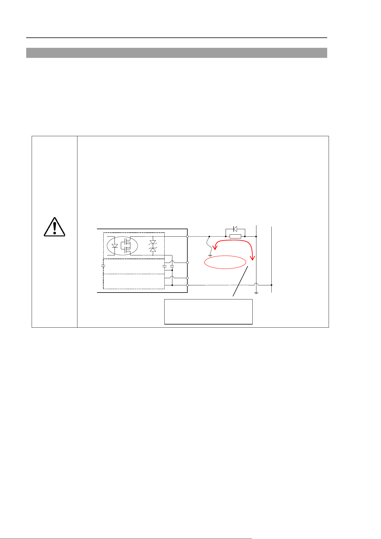
T3-B T6-B Manipulator 12. Standard I/O Connector
114 T-B series Rev.6
12.2 Output Circuit
Rated Output Voltage : +12 V to +24 V ±10%
Maximum Output Current : TYP 100 mA/1 output
Output device : PhotoMOS relay
ON resistance : Less than 0.7 Ω
The following two wirings are available since non-polar PhotoMOS relay is used for output
circuit.
CAUTION
Be sure to wire the output circuit properly because it has no protection circuitry
for short-circuit and reverse-
connection. Improper wiring may cause malfunction
of the parts on the board and then improper function of the robot system.
To comply with European Machinery Directive, use plus common (PNP) to
prevent the load from
unintended operation in the event of a ground fault in the
wiring between the controller and the load.
L
Output No.0
I/O connector
Omit
+DC
Output common
(+DC)
Load
GND
Ground fault
Plus common (PNP) connection
Even if a ground fault occurs,
the
current does not flow to
the load and does not operate.
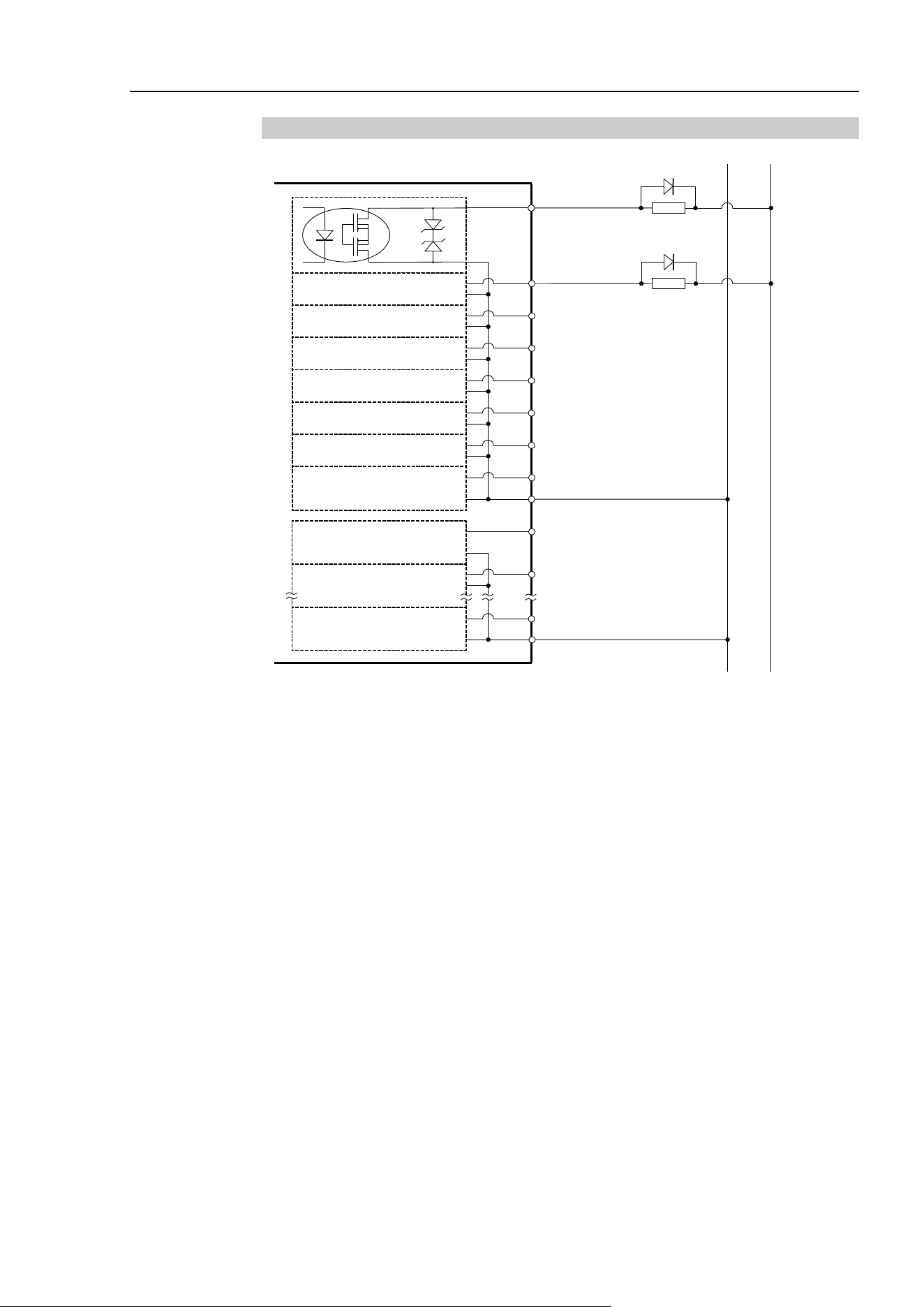
T3-B T6-B Manipulator 12. Standard I/O Connector
T-B series Rev.6 115
12.2.1 Typical Output Circuit Application 1: Sink Type (NPN)
L
L
1 Output No.0
(Same as above)
Omit
+DC
6 Output No.8
15 Output No.9
16 Output No.11
10 Output No.1
2 Output No.2
11 Output No.3
3 Output No.4
12 Output No.5
4 Output No.6
13 Output No.7
5 Output No.0 to 7 common
(GND)
Load
GND
14 Output No.8 to 11 common
(GND)
Standard I/O (output) connector
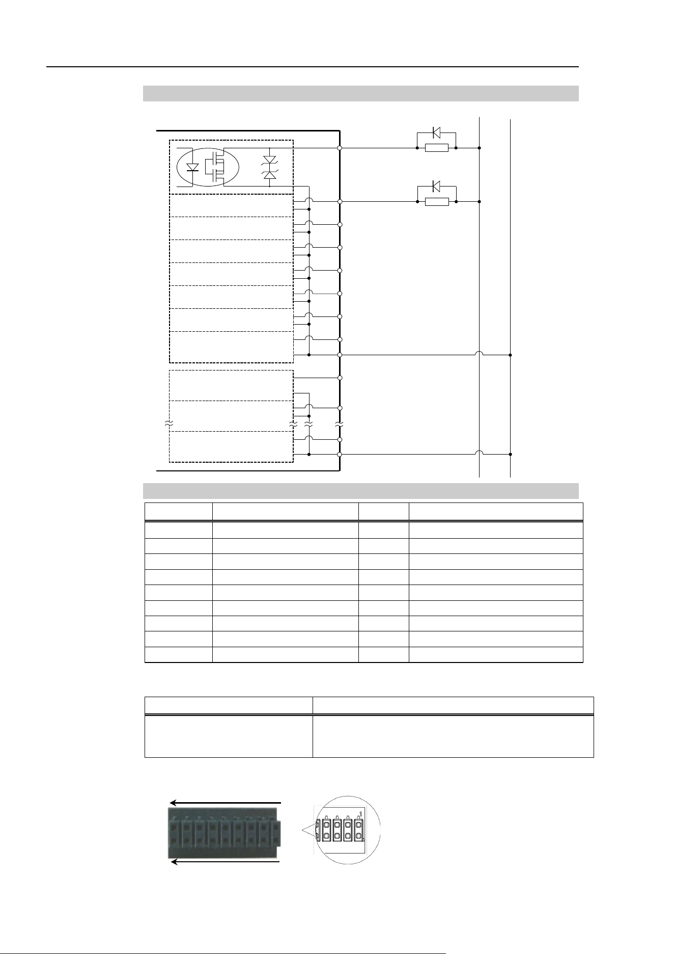
T3-B T6-B Manipulator 12. Standard I/O Connector
116 T-B series Rev.6
12.2.2 Typical Output Circuit Application 2: Source Type (PNP)
L
L
1 Output No.0
(Same as
above)
Omit
+DC
6 Output No.8
15 Output No.9
16 Output No.11
10 Output No.1
2 Output No.2
11 Output No.3
3 Output No.4
12 Output No.5
4 Output No.6
13 Output No.7
5 Output No.0 to 7 common
(+DC)
Load
GND
14 Output No.8 to 11 common
(+DC)
Standard I/O (output) connector
12.2.3 Pin Assignments of Output Circuit
Pin No.
Signal Name
Pin No.
Signal Name
1
Output No. 0 (Ready)
10
Output No.1 (Running)
2
Output No.2 (Paused)
11
Output No.3 (Error)
3
Output No.4
12
Output No.5 (SafeguardOn)
4
Output No.6 (SError)
13
Output No.7 (Warning)
5
Output common No. 0 to 7
14
Output common No. 8 to 11
6
Output No. 8 (EstopOff)
15
Output No. 9
7
Output No.10
16
Output No.11
8
Not Used
17
Not Used
9
Not Used
18
Not Used
Remote function inside ( ) in the table above is initially assigned to output from 0 to 8. For
further details, refer to “14. I/O Remote Settings”.
Connector
Connector model
I/O (Output) Connector
DMC 0,5/9-G1-2,54 P20THR R44 (Board side)
DFMC 0,5/ 9-ST-2,54 (Cable side)
(PHOENIX CONTACT)
* I/O connector is included with shipment.
I/O (Output) Connector pin assignment
9
1
18
10
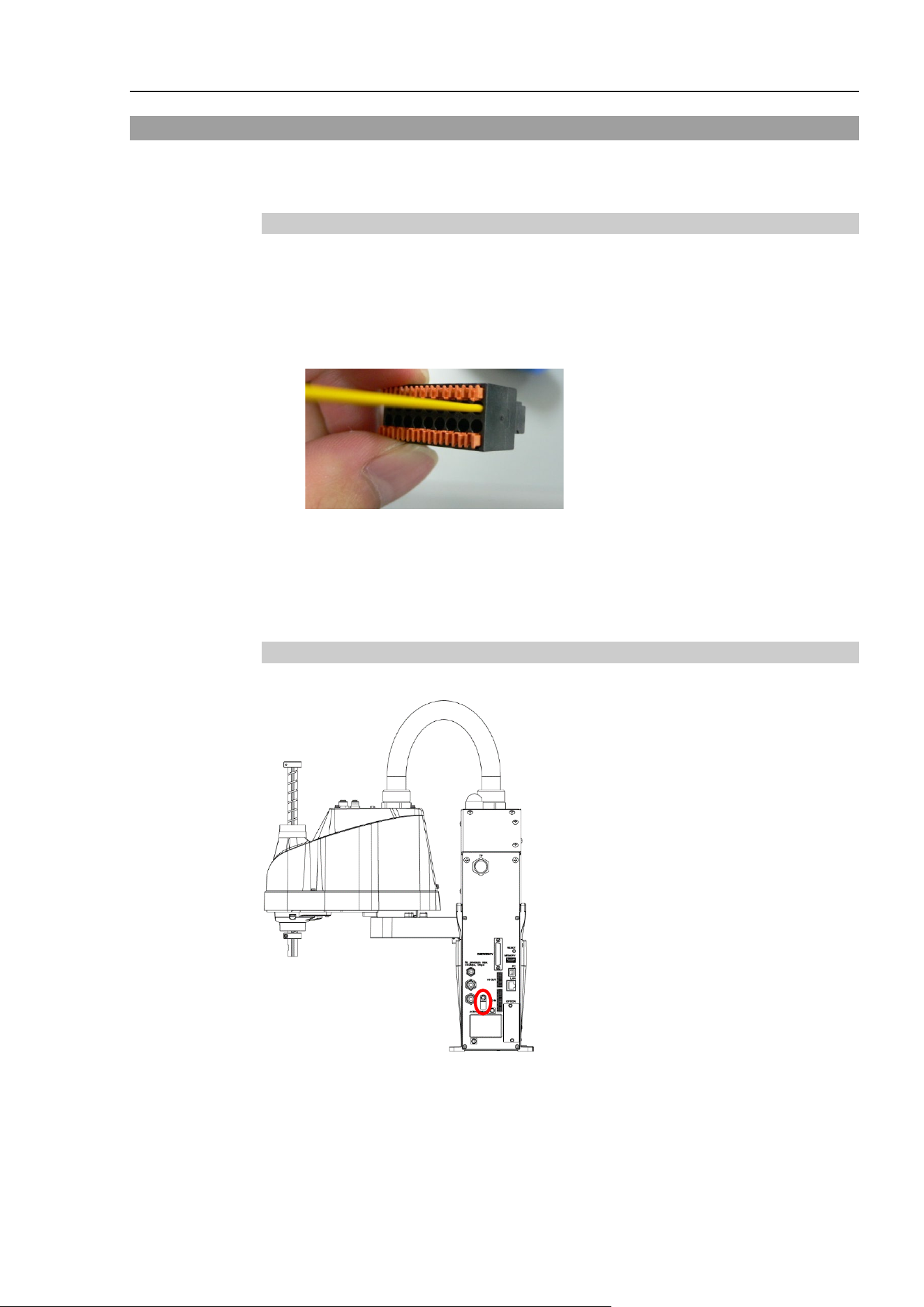
T3-B T6-B Manipulator 12. Standard I/O Connector
T-B series Rev.6 117
12.3 I/O Cable Product Procedure
The following describes I/O cable product procedure for connecting user’s input/output
devices.
12.3.1 I/O Cable Connecting Method
(1) Prepare for I/O connector and cable which are included with shipment.
Adaption cable:
Electric wire capacity: 0.14 to 0.5mm
2
Wire type: single wire, stranded wire, stranded wire with rod terminal.
(2) Push the edge of cable into wire insertion slot.
For single wire and stranded wire,
peel off the covering of the cable.
- If using a twisted wire or finer single wire, insert it while pushing orange colored
open button.
- Orange push pins are easy to come off. Be careful during operation.
- There is a cable check hole above the open button. You can check cables using tester.
12.3.2 How to Fix the I/O Cable
You can fix the I/O cables using cable clamp on the back of the manipulator.
Cable clamp
(Illustration: T3-B401S)
Fixing cables with I/O cable clamp, wiring of I/O cables is difficult to disconnect.
NOTE
NOTE
T3-B T6-B Manipulator 13. Hand I/O Connector
118 T-B series Rev.6
13. Hand I/O Connector
CAUTION
Be careful not to exceed rated current range or rated current which are defined
in manual.
If exceeding rated current, the Manipulator may now operate at worst.
Hand I/O connector is a connector for connecting your input/output equipment to the system.
It is mounted on upper of Arm #2.
For cable wiring, refer to “3.7.2 Noise Countermeasures” in order to prevent noise.
Also, for details of standard I/O mounted on back side of the manipulator, refer to “12
Standard. I/O Connector”.
13.1 Power Supply Specifications
Hand I/O connector has a power supply which user can use. Enable to use this power supply
to operate external devices.
Be careful not to exceed allowable current when using power supply.
Voltage: 24V ±5%
Allowable current: T3-B: 500mA
T6-B: 700mA
Connector name
Polarity
Pins
Bit number
Hand I/O connector
Input
6
18-23
Output
4
12-15
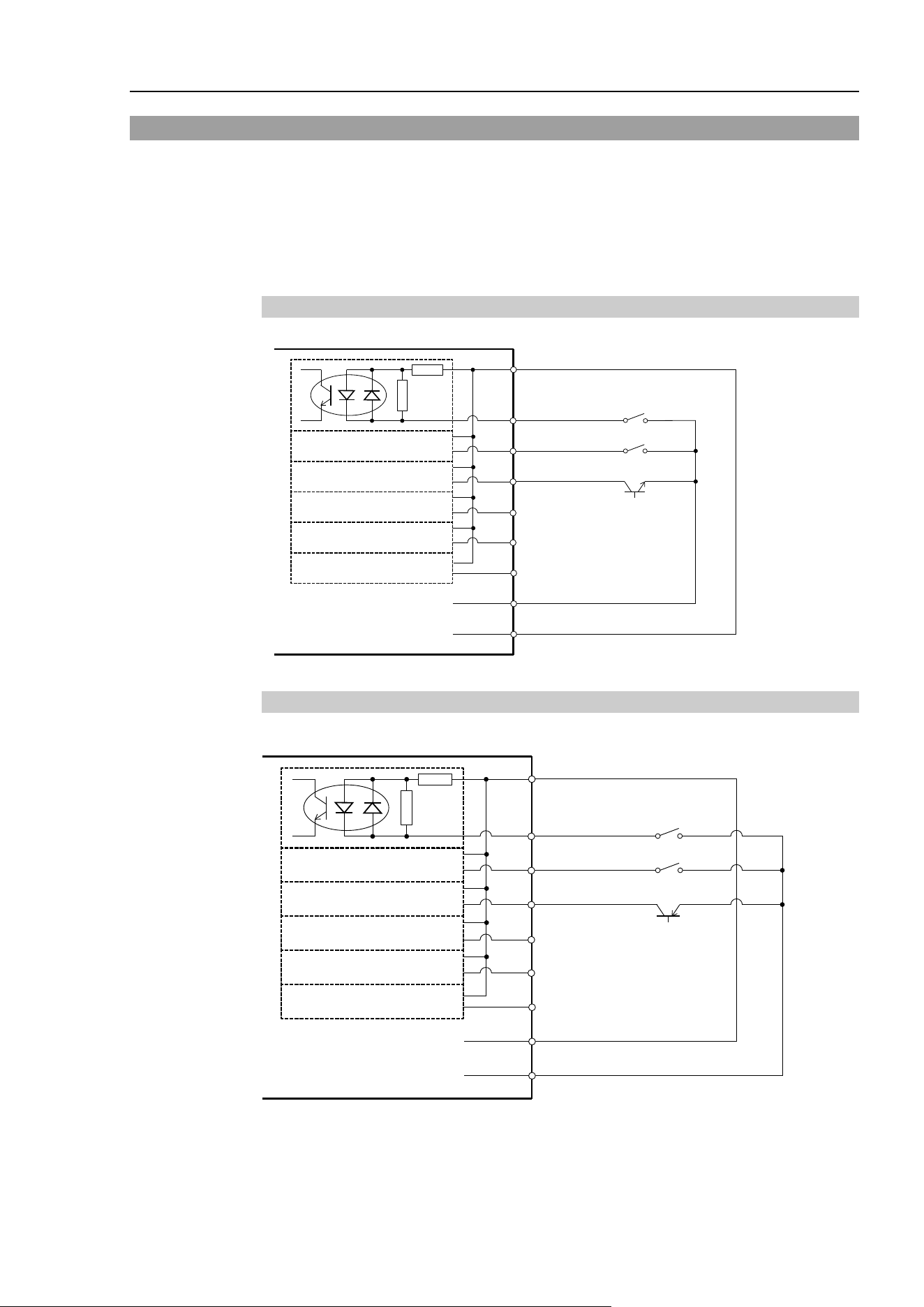
T3-B T6-B Manipulator 13. Hand I/O Connector
T-B series Rev.6 119
13.2 Input Circuit
Input Voltage Range : +12 to 24 V ±10%
ON Voltage : +10.8 V (min.)
OFF Voltage : +5 V (max.)
Input Current : 10 mA (TYP) at +24 V input
Two types of wiring are available for use with the two-way photo coupler in the input circuit.
13.2.1 Typical Input Circuit Application 1: Source Type
4 Input No.18 to 23 common
1 Input No.18
9 Input No.19
2 Input No.20
10 Input No.21
3 Input No.22
11 Input No.23
13 GND
5 +DC
Hand I/O connector
(Same as above)
GND
+DC
13.2.2 Typical Input Circuit Application 2: Sink Type
4 Input No.18 to 23 common
1 Input No.18
9 Input No.19
2 Input No.20
10 Input No.21
3 Input No.22
11 Input No.
23
13 GND
5 +DC
(Same as above)
Hand I/O connector
+DC
GND
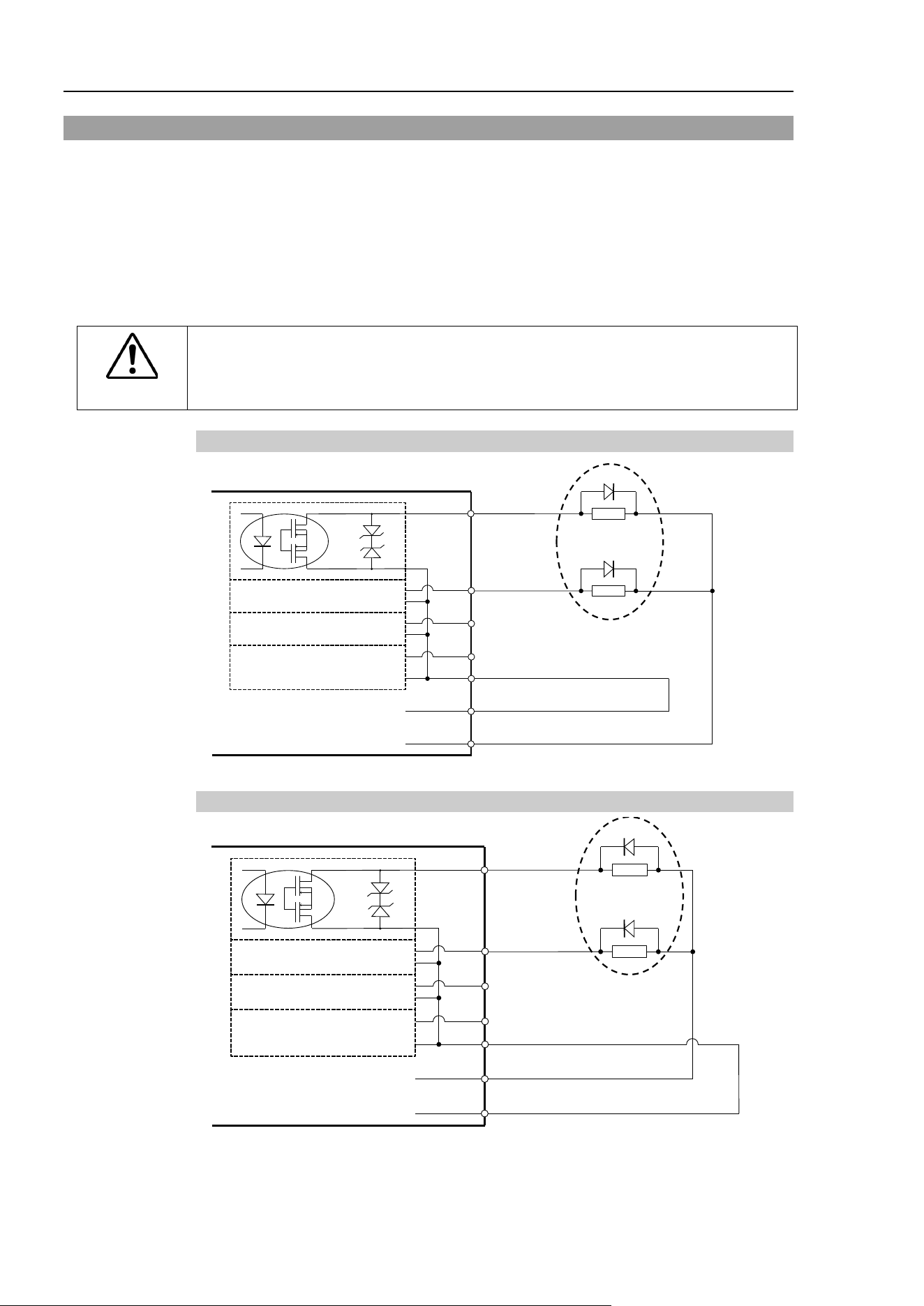
T3-B T6-B Manipulator 13. Hand I/O Connector
120 T-B series Rev.6
13.3 Output Circuit
Rated Output Voltage : +12 V to +24 V ±10%
Maximum Output Current : TYP 100 mA/1 output
Output device : PhotoMOS relay
On resistance : Less than 0.7 Ω
The following two wirings are available since non-polar PhotoMOS relay is used for output
circuit.
CAUTION
Be sure to wire the output circuit properly because it has no protection circuitry
for short-circuit and reverse-connection. Improper wiring may cause malfunction
of the parts on the board and then improper function of the robot system.
13.3.1 Typical Output Circuit Application 1: Sink Type (NPN)
L
L
6 Output No.12
(Same as above)
+DC
14 Output No.13
7 Output No.14
15 Output No.15
Load
GND
8 Output No.12 to 15 common (GND)
Hand I/O connector
13 GND
5 +DC
Do not exceed the
allowable current of
the hand I/O
13.3.2 Typical Output Circuit Application 2: Source Type (PNP)
L
L
6 Output
(Same as above)
+DC
14 Output No.13
7 Output No.14
15 Output No.15
Load
GND
8 Output No.12 to 15 common
(GND)
Hand I/O Connector
13 GND
5 +DC
Do not exceed the
allowable current of
the hand I/O
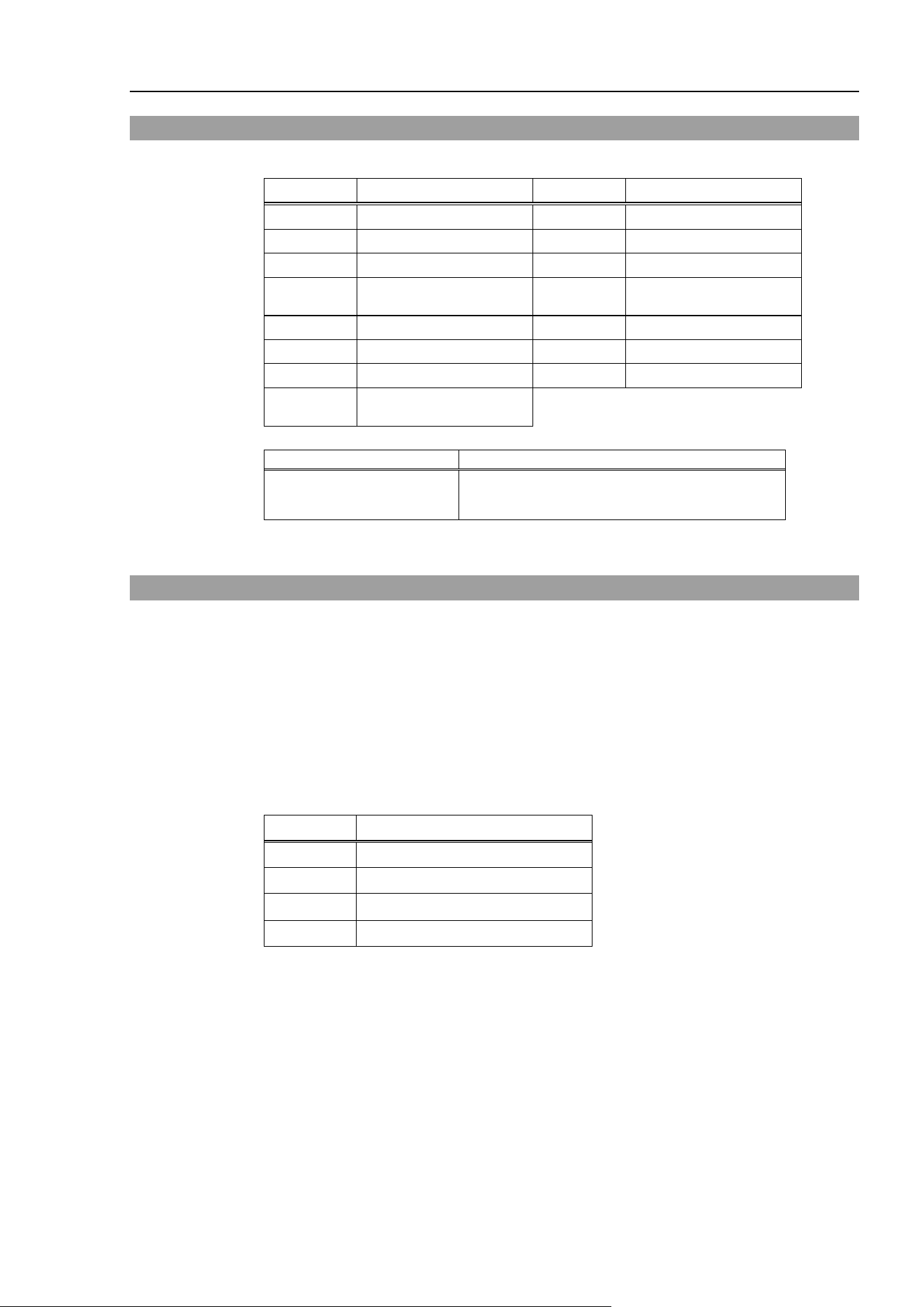
T3-B T6-B Manipulator 13. Hand I/O Connector
T-B series Rev.6 121
13.4 Pin Assignments
The following is pin assignments of Hand I/O connector (D-sub 15 pin male).
Pin No.
Signal Name
Pin No.
Signal Name
1
Input No.18
9
Input No.19
2
Input No.20
10
Input No.21
3
Input No.22
11
Input No.23
4
Input common
No.18 to 23
12
Not Used
5
+24V
13
GND
6
Output No.12
14
Output No.13
7
Output No.14
15
Output No.15
8
Output common
No.12 to 15
Connector
Standard
Hand I/O connector
D-Sub 15 pin female (manipulator side)
D-Sub 15 pin male (cable side)
* I/O connector is included with shipment.
13.5 How to Control Hand I/O
T-B series has I/O (Input: 6 bit, Output: 4 bit) for hand control I/O.
Input bit port: 18, 19, 20, 21, 22, 23
Output bit port: 12, 13, 14, 15
How to operate
Hand I/O is only supported for bit port operation commands. Byte or word commands are
not supported.
Available commands
Command
Function
Sw
Input bit port I/O.
SetSw
Set an input of virtual I/O.
On Turn ON the output bit.
Off
Turn OFF the output bit.
Restriction 1: Remote I/O
Hand I/O cannot be set in Remote I/O.
Restriction 2: Input/Output by byte port or word port
There are restrictions to operate input/output of standard I/O by byte or word port since
hand I/O is included in byte port and word port.
Input: Always “0” is read for bit of hand I/O.
Output: Execute error occurs when specifying “1” for bit of hand I/O.
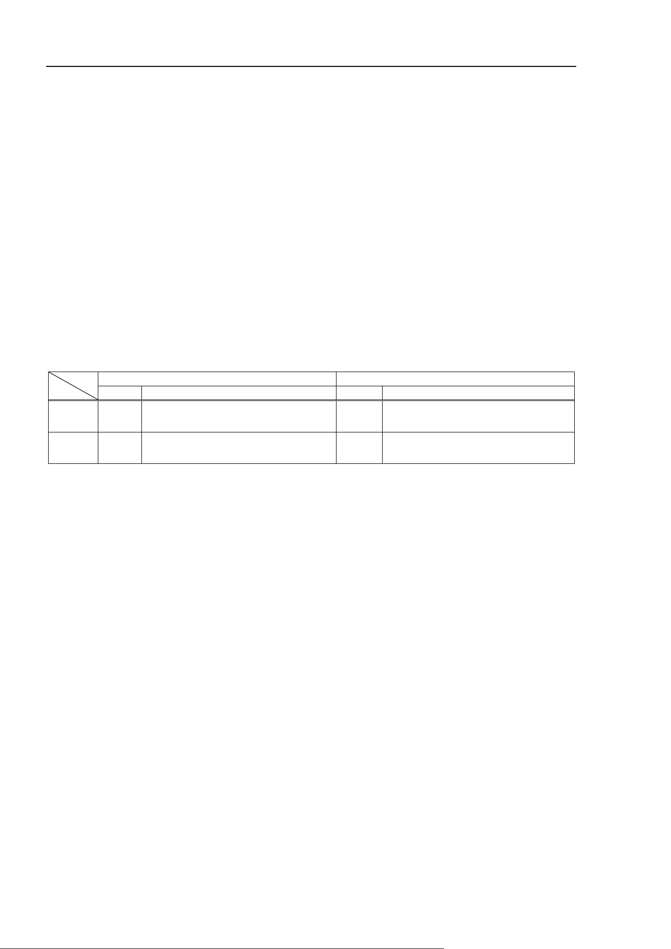
T3-B T6-B Manipulator 13. Hand I/O Connector
122 T-B series Rev.6
Input example:
When operating byte input by following conditions
Input hand I/O23: ON
Input standard I/O bit: 16=OFF, 17=ON
In(2)---> 0x02 (0000 0010B)
Output example:
When operating byte output by following conditions
Output standard I/O bit port 11=ON,10~8=OFF
Out 1,'H08
Error output example:
When operating byte output by following conditions
Output standard I/O bit port 11=ON,10~8=OFF
Out 1,'H18 <--- Error since hand I/O bit is ON
Byte port
Word port
Port
Description
Port
Description
Input 2
“0” is read for upper 6 bits
0000 00xx
1
“0” is read for upper 6 bits
0000 00xx xxxx xxxx
Output 1
Always specify “0” for upper 4 bits.
0000 xxxx
0
Always specify “0” for upper 4 bits.
0000 xxxx xxxx xxxx
T3-B T6-B Manipulator 14. I/O Remote Settings
T-B series Rev.6 123
14. I/O Remote Settings
This section describes the functions and timings of input and output signals.
The remote functions may be assigned to your standard I/O board(s), or fieldbus I/O board(s)
to enhance robot system control - either from an operational unit of your choice or a
sequencer.
Remote function is initially assigned to both input and output from 0 to 8.
To accept external remote inputs, assign the remote function and the control device is remote.
For further details, refer to the section, Remote Control Software Configuration in EPSON
RC+ 7.0 User’s Guide - Remote Control.
The user defines the I/O number that a remote function is assigned to using software
configuration. For further details, refer to the section, Remote Control Software
Configuration in EPSON RC+ 7.0 User’s Guide - Remote Control.
For details about I/O cable connection, refer to sections “12: Standard I/O Connector”, “13.
Hand I/O Connector” and “17. Fieldbus I/O”.
For details about communication with external equipment, refer to EPSON RC+ 7.0 User’s
Guide -12. Remote Control.
CAUTION
When using remote I/O, always make sure of the following. Using the robot
system under unsatisfactory conditions may cause malfunction of the system
and/or safety problems.
- This signal is not safety signal. Do not this use for safety functions.
- Assign remote functions to inputs/outputs correctly and wire correctly when
setting up remote I/O signals.
- Make sure that the functions correspond to the correct input/output signals
before turning ON the system.
When verifying the robot system operation, prepare for failures with initial
settings or wiring. If the Manipulator functions unusually by the failures with initial
settings or wiring, press the Emergency Stop switch immediately to stop the
Manipulator.
Remote function is available when virtual I/O is enabled.
When you set up a remote I/O signal, please either keep a written record of the settings or
store the data in a file for later reference.
When you set up a fieldbus I/O signal to the remote function, response depends on the baud
rate of the fieldbus. For details of fieldbus response, refer to Robot Controller Option
Fieldbus I/O.
Hand I/O connecter cannot be set in remote signal.
NOTE

T3-B T6-B Manipulator 14. I/O Remote Settings
124 T-B series Rev.6
14.1 I/O Signal Description
Remote function is initially assigned to both input and output from 0 to 8.
To change the function assignment from the initial setting, use EPSON RC+ 7.0.
To use all signals, you will need to add Fieldbus I/O module.
14.1.1 Remote Input Signals
Remote inputs are used to control the Manipulators and start programs. Certain conditions
must be met before inputs are enabled, as shown in the table below.
To accept external remote inputs, assign the remote function and set remote to the control
device. When external remote input is available, “AutoMode output” turns ON.
Except “SelProg”, the signals execute each function when the signal starts in input
acceptance condition. The function executes automatically. Therefore, no special
programming is needed.
When an error occurs, you must execute a “Reset” to clear the error condition before any
other remote input commands can be executed. Use the “Error output” and “Reset input” to
monitor the error status and clear error conditions from the remote device.
Name Initial Description
Input Acceptance
Condition (*1)
Start 0
Execute function selected at SelProg.
(*2)
(*13)
Ready output ON
Error output OFF
EStopOn output OFF
SafeguardOn output OFF
EStopOff output ON
Pause input OFF
Stop input OFF
SelProg1
SelProg2
SelProg4
SelProg8
SelProg16
SelProg32
1
2
3
Not Set
Not Set
Not Set
Specify the executing Main function
number. (*2)
Stop
4
All tasks and commands are stopped.
Pause
5
All tasks are paused. (*3)
Running output ON
Continue 6
Continue the paused task.
Paused output ON
Pause input OFF
Stop input OFF
Reset
7
Reset emergency stop and error. (*4)
Ready output ON
Shutdown
Not set
Terminates the system
ForcePowerLow
Not Set
Operates as the forced low power function.
The manipulator is operated in the low
power mode.
Power High control from the command is
not accepted.
Executes the following according to the
manipulator preferences.
Stops or temporarily stops all the tasks and
commands. (*12)
Any time
This input is acceptable
even AutoMode output is
OFF.
SelRobot
Not Set
Changes the output condition of MotorsOn,
AtHome, PowerHigh, and MCalReqd.(*9)
NOTE

T3-B T6-B Manipulator 14. I/O Remote Settings
T-B series Rev.6 125
Name Initial Description
Input Acceptance
Condition (*1)
SelRobot1
SelRobot2
SelRobot4
SelRobot8
SelRobot16
Not set
Specify the number of manipulator which
executes a command. (*5)
SetMotorsOn
Not set
Turn ON manipulator motors. (*5) (*6)
Ready output ON
EStopOn output OFF
SafeguardOn output OFF
EStopOff output ON
SetMotorOff input OFF
SetMotorsOff
Not set
Turn OFF manipulator motors. (*5)
Ready output ON
SetPowerHigh
Not set
Set the manipulator power mode to High
(*5)
Ready output ON
EStopOn output OFF
SafeguardOn output OFF
EStopOff output ON
SetPowerLow input OFF
SetPowerLow
Not set
Set the manipulator power mode to Low.
(*5)
Ready output ON
Home
Not set
Move the manipulator Arm to the home
position defined by the user.
Ready output ON
Error output OFF
EStopOn output OFF
SafeguardOn output OFF
EStopOff output ON
MotorsOn output ON
Pause input OFF
Stop input OFF
MCal
Not set Execute MCal (*5) (*7)
Ready output ON
Error output OFF
EStopOn output OFF
SafeguardOn output OFF
EStopOff output ON
MotorsOn output ON
Pause input OFF
Stop input OFF
Recover
Not set
After the safeguard is closed, recover to the
position where the safeguard is open.
Paused output ON
Error output OFF
EStopOn output OFF
SafeguardOn output OFF
EStopOff output ON
RecoverReqd output ON
Pause input OFF
Stop input OFF
ResetAlarm
Not Set
Cancel the alarm (*11)
SelAlarm1
SelAlarm2
SelAlarm4
SelAlarm8
Not Set Specify the alarm number to cancel (*10)

T3-B T6-B Manipulator 14. I/O Remote Settings
126 T-B series Rev.6
Name Initial Description
Input Acceptance
Condition (*1)
ALIVE Not Set
Input signal for alive monitoring of the
manipulator. Same signal as the input will
be output to ALIVE output. The master
equipment can perform alive monitoring of
the manipulator by switching the input
periodically and checking the output signal.
ExtCmd_0-15
Not Set
For extended remote I/O command.
For details, refer to the following manual.
Remote Control Reference
4. Remote I/O to Be Used
ExtCmd_16-31
Not Set
ExtCmd_32-47
Not Set
ExtCmd_48-63
Not Set
ExtCmd_64-79
Not Set
ExtCmd_80-95
Not Set
ExtCmd_96-111
Not Set
ExtCmd_112-
127
Not Set
(*1) “AutoMode output” ON is omitted from the table. This is an input acceptance condition for all functions.
(*2)
“Start input” executes Function specified by the following six bits: SelProg 1, 2, 4, 8, 16, and 32.
Function name
SelProg1
SelProg2
SelProg4
SelProg8
SelProg16
SelProg32
Main
0
0
0
0
0
0
Main1
1
0
0
0
0
0
Main2
0
1
0
0
0
0
Main3
1
1
0
0
0
0
.
.
.
Main60
0
0
1
1
1
1
Main61
1
0
1
1
1
1
Main62
0
1
1
1
1
1
Main63
1
1
1
1
1
1
0=OFF, 1=ON
(*3) “NoPause task” and “NoEmgAbort task” do not pause.
For details, refer to EPSON RC+ 7.0 Online Help or Pause in SPEL
+
Language Reference.
(*4) Turns OFF the I/O output and initializes the manipulator parameter.
For details, refer to EPSON RC+ 7.0 Online Help or Reset in SPEL
+
Language Reference.
(*5) The values specified by “SelRobot1, 2, 4, 8, and 16” correspond to the robot numbers, when multiple robots
are connected to the controller.
Robot
number
SelRobot1 SelRobot2 SelRobot4 SelRobot8 SelRobot16
0 (All)
0
0
0
0
0
1
1
0
0
0
0
2
0
1
0
0
0
3
1
1
0
0
0
.
.
.
13
1
0
1
1
0
14
0
1
1
1
0
15
1
1
1
1
0
16
0
0
0
0
1
0=OFF, 1=ON

T3-B T6-B Manipulator 14. I/O Remote Settings
T-B series Rev.6 127
(*6) Initializes the manipulator parameter.
For details, refer to EPSON RC+ 7.0 Online Help or Motor in SPEL
+
Language Reference.
(*7) For details, refer to EPSON RC+ 7.0 Online Help or MCal in SPEL
+
Language Reference.
(*8) This is for experienced users only. Make sure that you fully understand the input specification before
using.
CmdRunning output and CmdError output will not change for this input.
“NoEmgAbort task” will not stop by this input.
When the input changes from ON to OFF, all tasks and commands will stop.
(*9) This function changes the output condition of MotorsOn, AtHome, PowerHigh, and MCalReqd.
By setting this signal with the condition selected using SelRobot1 - SelRobot16, you can switch the
output condition.
Once you select the condition, it will be kept until you change it or turn off / restart the Controller. All
manipulators are selected as default.
(*10) The values specified by “SelAlarm1, 2, 4, and 8” correspond to the alarm numbers.
Alarm #
Target
SelAlarm1
SelAlarm2
SelAlarm4
SelAlarm8
1
Controller battery
1
0
0
0
2
-
0
1
0
0
3
Manipulator grease
1
1
0
0
4
-
0
0
1
0
5
-
1
0
1
0
6
-
0
1
1
0
7
-
1
1
1
0
8
-
0
0
0
1
9
-
1
0
0
1
0=OFF, 1=ON
The following parts are subject to grease up.
Ball screw spline unit on the Joint # 3
(*11) The specified alarm can be canceled by selecting the conditions using SelAlarm1-SelAlarm8 and setting
this signal.

T3-B T6-B Manipulator 14. I/O Remote Settings
128 T-B series Rev.6
(*12) Operation of all tasks and commands, power mode of the manipulator, and PowerHigh command by the
setting of the manipulator preferences.
Preferences (1): “Motor power low when ForcePowerLow signal OFF”
Preferences (2): “ForcePowerLow signal change pauses all tasks”
For details of the manipulator preferences, refer to EPSON RC+ 7.0 User’s Guide
[Setup]-[System Configuration]-[Controller]-[Preferences] in 5.12.2 [System
Configuration] Command (Setup Menu).
Preferences (1) Preferences (2) ForcePowerLow
All tasks and
commands
Power mode PowerHigh
0
0
1→0
Stop
Low only
Accept
0
0
0→1
Stop
Low only
Not accept
0
1
1→0
Continue
High/Low
Accept
0
1
0→1
Temp. stop
Low only
Not accept
1
0
1→0
Stop
Low only
Not accept
1
0
0→1
Stop
Low only
Accept
1
1
1→0
Temp. stop
Low only
Not accept
1
1
0→1
Continue
High/Low
Accept
(*13) Do not execute the Restart command of the SPEL+ program and the Start signal of the remote input at the
same time. Error 2503 may occur when the programs are executed at the same time.

T3-B T6-B Manipulator 14. I/O Remote Settings
T-B series Rev.6 129
14.1.2 Remote Output Signals
Remote output is a function to output a status of the Manipulator or operation mode.
Remote outputs provide the assigned function using with any control device The outputs
execute automatically. Therefore, no special programming is needed.
Name
Initial
Description
Ready
0
Turns ON when the manipulator startup completes and no task is running.
Running 1
Turns ON when task is running.
However, turns OFF when “Paused output” is OFF.
Paused
2
Turns ON when pause task exists.
Error 3
Turns ON when an error occurs.
Use “Reset input” to recover from the error. (*13)
EStopOn Not set
Turns OFF except in Emergency Stop.
Turns ON in Emergency Stop.
Turns OFF when the controller power is OFF (*11)
SafeguardOn
5
Turns ON when the safeguard is open.
SError 6
Turns ON when critical error occurs.
When a critical error occurs, “Reset
input” does not function. Reboot the
controller to recover. (*13)
Warning 7
Turns ON when warning occurs.
The task runs as normal with the warning. However, be sure to eliminate the
cause of the warning as soon as possible. (*13)
EStopOff 8
Turns ON except in Emergency Stop.
Turns OFF in Emergency Stop.
Turns OFF when the controller power is OFF
MotorsOn
Not set
Turns ON when the manipulator motor is ON. (*5)
AtHome
Not set
Turns ON when the manipulator is in the home position. (*5)
PowerHigh
Not set
Turns ON when the manipulator’s power mode is High. (*5)
MCalReqd
Not set
Turns ON when the manipulator hasn’t executed MCal. (*5)
RecoverReqd Not set
Turns ON when at least one manipulator is waiting for Recover after the
safeguard is closed.
RecoverInCycle
Not set
Turns ON when at least one manipulator is executing Recover.
WaitingRC
Not set
Turns ON when the controller waits for RC+ to connect.
CmdRunning
Not set
Turns ON when an input command is executing.
CmdError
Not set
Turns ON when an input command cannot be accepted.
CurrProg1
CurrProg2
CurrProg4
CurrProg8
CurrProg16
CurrProg32
Not set Indicates the running or the last main function number (*1)
AutoMode
Not set
Turns ON in remote input acceptable status. (*2)
TeachMode
Not set
Turns ON in TEACH mode.
TestMode
Not set
Turns ON in TEST mode.
EnableOn
Not set
Turns ON when the enable switch is ON.

T3-B T6-B Manipulator 14. I/O Remote Settings
130 T-B series Rev.6
Name
Initial
Description
ErrorCode1
.
.
.
ErrorCode8192
Not set Indicates the error number.
InsideBox1
.
.
.
InsideBox15
Not set Turns ON when the manipulator is in the approach check area. (*3)
InsidePlane1
.
.
.
InsidePlane15
Not set Turns ON when the manipulator is in the approach check plane. (*4)
Alarm
Not set
Turns ON when any of the alarms is occurring. (*9)
Alarm1
Not set
Turns ON when a battery alarm of the manipulator is occurring. (*12)
Alarm2 Not set
Turns ON when a battery alarm of the manipulator connected to CU is occurring.
(*12)
Alarm3 Not set
Turns ON when a grease alarm of the manipulator connected to CU is occurring.
(*10) (*12)
Alarm4 Not set
Turns ON when a battery alarm of the manipulator connected to DU1 is
occurring. (*12)
Alarm5 Not set
Turns ON when a grease alarm of the manipulator connected to DU1 is occurring.
(*10) (*12)
Alarm6 Not set
Turns ON when a battery alarm of the manipulator connected to DU2 is
occurring. (*12)
Alarm7 Not set
Turns ON when a grease alarm of the manipulator connected to DU2 is occurring.
(*10) (*12)
Alarm8 Not set
Turns ON when a battery alarm of the manipulator connected to DU3 is
occurring. (*12)
Alarm9 Not set
Turns ON when a grease alarm of the manipulator connected to DU3 is occurring.
(*10) (*12)
PositionX
Not set
Outputs current X coordinate in the World coordinate system (*6) (*7)
PositionY
Not set
Outputs current Y coordinate in the World coordinate system (*6) (*7)
PositionZ Not set
Outputs current Z coordinate in the World coordinate system
(*6) (*7)
PositionU
Not set
Outputs current U coordinate in the World coordinate system (*6) (*7)
PositionV
Not set
Outputs current V coordinate in the World coordinate system (*6) (*7)
PositionW
Not set
Outputs current W coordinate in the World coordinate system (*6) (*7)
Torque1
Not set
Outputs the current torque value of Joint #1 (*6) (*7)
Torque2
Not set
Outputs the current torque value of Joint #2 (*6) (*7)
Torque3
Not set
Outputs the current torque value of Joint #3 (*6) (*7)
Torque4
Not set
Outputs the current torque value of Joint #4 (*6) (*7)
Torque5
Not set
Outputs the current torque value of Joint #5 (*6) (*7)
Torque6
Not set
Outputs the current torque value of Joint #6 (*6) (*7)
CPU
Not set
Outputs the CPU load factor of the user program (*8)
ESTOP
Not set
Outputs how many times emergency stops have been executed.
ALIVE Not set
Output signal for alive monitoring of the manipulator. The signal input by ALIVE
input will be output. The master equipment can perform alive monitoring of the
manipulator by switching the input periodically and checking the output signal.
T3-B T6-B Manipulator 14. I/O Remote Settings
T-B series Rev.6 131
Name
Initial
Description
ForceControlOn
Not set
Turns ON when the manipulator operating force control function. (*5)
ExtCmdGet
Not set
For extended remote I/O command.
For details, refer to the following manual.
Remote Control Reference 4. Remote I/O to Be Used
ExtRespSet
Not set
ExtCmdResult
Not set
ExtError
Not set
ExtResp_0-15
Not set
ExtResp_16-31
Not set
ExtResp_32-47
Not set
ExtResp_48-63
Not set
ExtResp_64-79
Not set
ExtResp_80-95
Not set
ExtResp_96-111
Not set
ExtResp_112-127
Not set
(*1) Outputs the current or the last function number of CurrProg1, 2, 4, 8, 16, or 32.
Function name
CurrProg1
CurrProg2
CurrProg4
CurrProg8
CurrProg16
CurrProg32
Main
0
0
0
0
0
0
Main1
1
0
0
0
0
0
Main2
0
1
0
0
0
0
Main3
1
1
0
0
0
0
.
.
.
Main60
0
0
1
1
1
1
Main61
1
0
1
1
1
1
Main62
0
1
1
1
1
1
Main63
1
1
1
1
1
1
0=OFF, 1=ON
(*2) Remote function is available in the following conditions.
- The setting is Auto mode and the control device is remote.
- The setting is Program mode and Remote I/O is enabled.
(*3) For details, refer to EPSON RC+ 7.0 Online Help or Box in SPEL
+
Language Reference.
(*4) For details, refer to EPSON RC+ 7.0 Online Help or Plane in SPEL
+
Language Reference.
T3-B T6-B Manipulator 14. I/O Remote Settings
132 T-B series Rev.6
(*5) Manipulator status is output as follows, according to the condition selected in SelRobot.
Wait at least 40 ms before inputting the signal after changing the condition in SelRobot.
Name
(SelRobot1- SelRobot16) condition when inputting SelRobot
0: All robots are selected 1 - 16: Particular robot number is
selected
MotorsOn
Turns ON when at least one
manipulator motor is ON.
Turns ON when the motor of the selected
manipulator is ON.
AtHome
Turns ON when all manipulators are
in the home position.
Turns ON when the selected manipulator is
in the home position.
PowerHigh
Turns ON when at least one
manipulator’s power mode is High.
Turns ON when the selected manipulator’s
power mode is High.
MCalReqd
Turns ON when at least one
manipulator hasn’t executed MCal.
Turns ON when the selected manipulator
hasn’t executed MCal.
(*6) Outputs information of the selected robot when SelRobot1, SelRobot2, SelRobot4, SelRobot8, and
SelRobot16 are set. If not, information of Robot 1 will be output.
(*7) Outputs information in Real format.
(*8) Outputs the total load factor of the user created tasks. For details on the CPU load factor, refer to the task
manager.
(*9) The signal turns on when the alarm occurs in the manipulator alarm information.
(*10) For details about the target of grease up, refer to the following.
“Regular Inspection 1.3 Greasing”
(*11) It is not recommended that EStopOn does not match the output with emergency stop state and controller
off state. To output the state of emergency stop, assign EStopOff.
(*12) The occurrence of battery alarm and grease alarm is monitored every 5 minutes.
The alarm occurrence and output timing of the controller are different.
It may be output up to 5 minutes after the controller alarm occurs.
“
Alarm” will on when battery alarm or grease alarm of Controller or Manipulator occurs with “Robot
maintenance” enabled. For details of Robot maintenance, refer to “Alarm” section of maintenance manual.
(*13) Following shows status number/error number of output (Error, SError, Warning).
Name
Error Number
Error
1000 to 8000s
SError
9000s
Warning
410 to 900s
For more information of status number/error number, refer to following manual.
“Status Code / Error Code List” manual
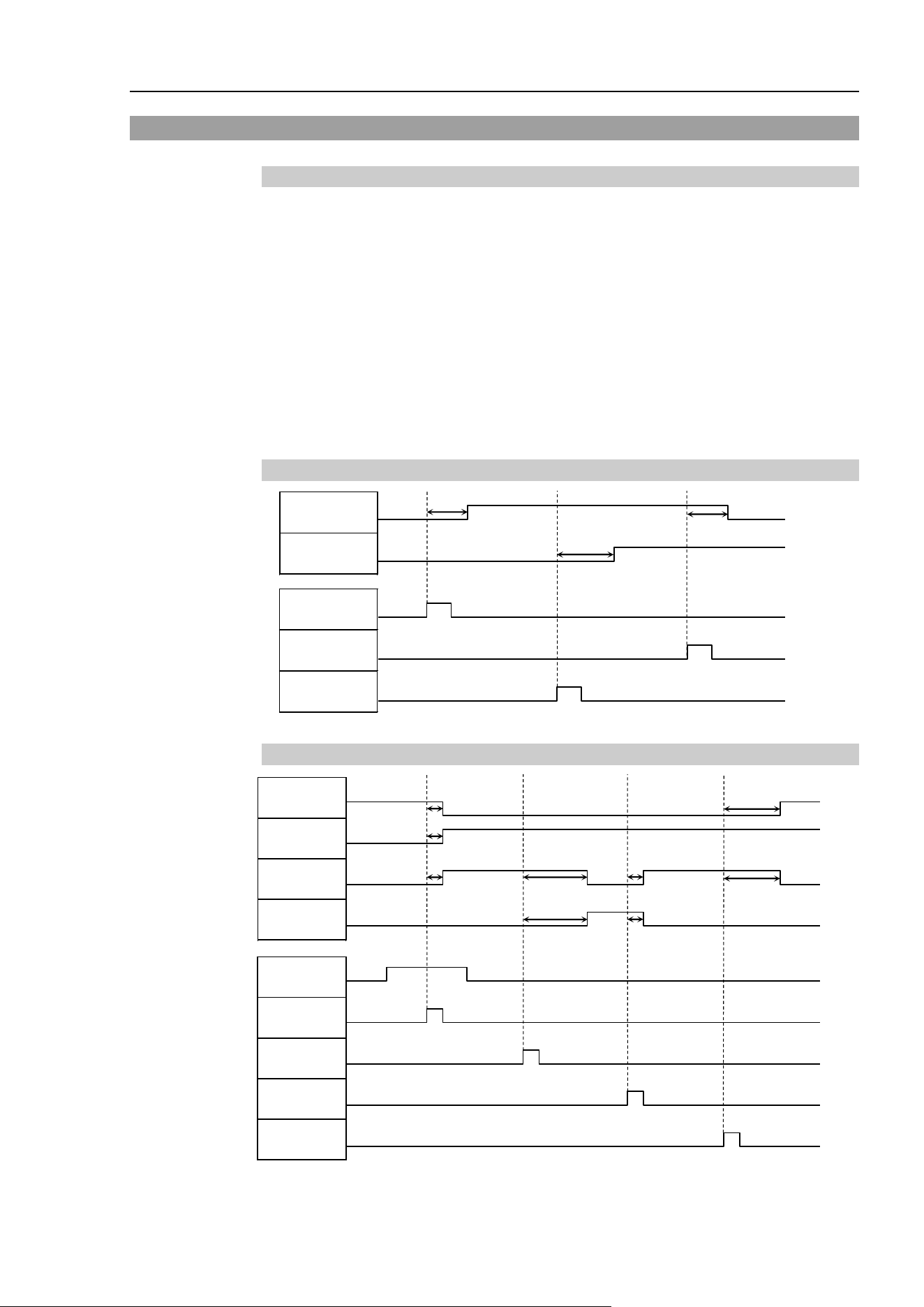
T3-B T6-B Manipulator 14. I/O Remote Settings
T-B series Rev.6 133
14.2 Timing Specifications
14.2.1 Precautions for Remote Input Signals
The following charts indicate the timing sequences for the primary operations of the
Controller.
The indicated time lapses (time durations) should be referred to only as reference values
since the actual timing values vary depending on the number of tasks running, as well as
CPU speed of the Manipulator. Check carefully and refer to the following charts for the
timing interrelation when you enter an input signal.
During system design, make sure that you actuate only one remote input operation at a time,
otherwise an error will occur.
The pulse width of an input signal must be 25 or more milliseconds to be detected.
[Unit: ms]
14.2.2 Timing Diagram for Operation Execution Sequence
940
1250
Depending on
HOME motion
MotorsOn
Output
AtHome
Output
SetMotorsOn
Input
SetMotorsOff
Input
Home
Input
14.2.3 Timing Diagram for Program Execution Sequence
34
34
34
110
110
34
34
410
Ready
Output
CurrProg1
Output
Running
Output
* Paused
Output
SelProg1
Input
Start
Input
Pause
Input
Continue
Input
Stop
Input
410
* The duration varies depending on the Quick Pause (QP) setting and the program’s
operating status at the time of Pause input
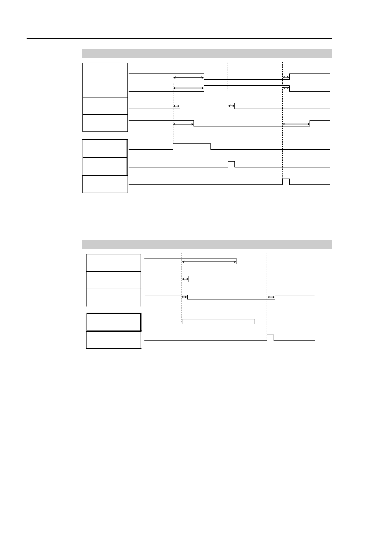
T3-B T6-B Manipulator 14. I/O Remote Settings
134 T-B series Rev.6
14.2.4 Timing Diagram for Safety Door Input Sequence
8
1052
1052
500
9
11
11
928
Running
Output
Paused
Output
SafeguardOn
Output
MotorsOn
Output
SD Signal
(*1)
SDLATCH
Signal
(*1)
Continue
Input
[Unit: msec]
(*1) A logical signal to explain the timing of internal processing of the controller.
For details about input signals name and operating conditions, refer to the 11.3 Pin
Assignments.
14.2.5 Timing Diagram for Emergency Stop Sequence
920
7
5
Running
Output
MotorsOn
Output
EStopOff
Output
ESW Signal
(*1)
Reset Signal
Input
7
[Unit: msec]
(*1) A logical signal to explain the timing of internal processing of the controller.
For details about input signals name and operating conditions, refer to the 11.3 Pin
Assignments.
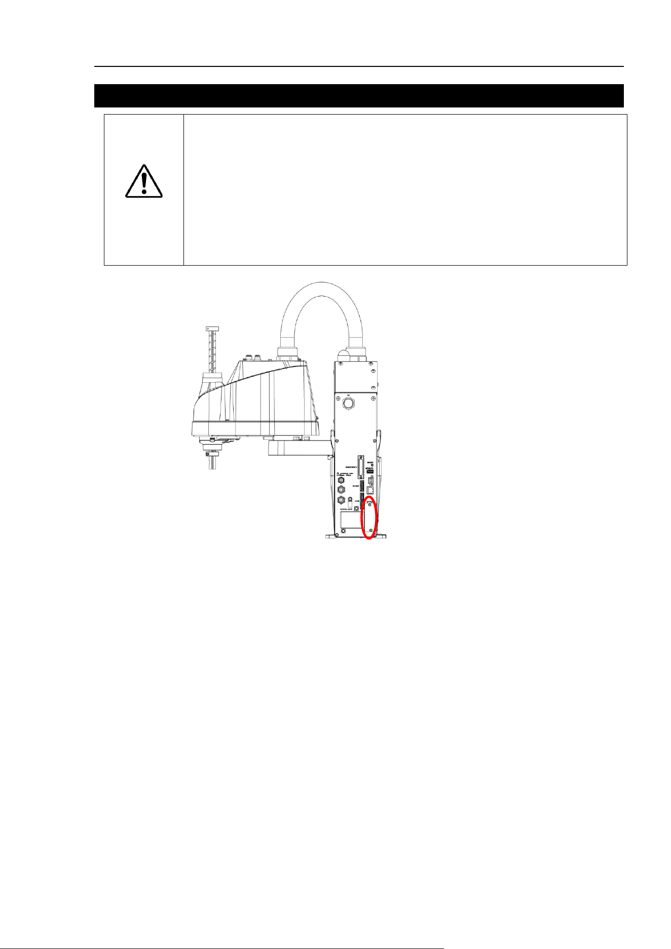
T3-B T6-B Manipulator 15. SD Card Slots
T-B series Rev.6 135
15. SD Card Slots
CAUTION
Do not use any SD card other than accessories.
If using other SD card, system may not operate properly.
SD card is only available for robot system.
SD card is written only for robot system. Unable to use for reading/writing data.
If you write data on SD card, robot system may not operate properly.
Replacing SD card should be performed by a person who has taken proper
training. For details, refer to “Safety Manual Training”.
SD card slot
(Option slot: inside)
(Illustration: T3-B401S)
SD card slot is a slot for inserting SD card.
Firmware to operate the manipulator is written on SD card.
Reference: T-B series Maintenance Manual 14.3 Replacement of SD card
The SD card insertion direction differs depending on the product shipment time.
NOTE

T3-B T6-B Manipulator 16. Fieldbus I/O
136 T-B series Rev.6
16. Fieldbus I/O
Fieldbus I/O of the T-B series supports the following model.
DeviceNet™
PROFIBUS-DP
EtherNet/IP™
Modbus
CC-Link
PROFINET
Eth er CAT®
For details, refer to the following manuals.
Robot Controller Option Fieldbus I/O
EPSON RC+ 7.0 User’s Guide 11.7 Fieldbus Slave I/O
For installing method of Fieldbus I/O module, refer to the following manual.
T-B series Maintenance Manual 14.6 Fieldbus I/O

T3-B T6-B Manipulator 17. Restrictions
T-B series Rev.6 137
17. Restrictions
For T-B series manipulator, there are commands with restrictions or may cause an error if
executing. However, error does not occur when building a program.
Also, some functions have restrictions.
17.1 Commands Cannot Use
The following commands/ functions are not available.
AbortMotion Aborts a motion command and puts the running task in error status.
Toff Turns off execution line display on the LCD.
Ton Specifies a task which shows an execution line on the LCD.
ShutDown Shuts down EPSON RC+ and optionally shuts down or restarts
Windows.
WindowsStatus Returns the Windows startup status.
17.2 Commands Cause Motion Error If Specifying RS-232C
If specifying RS-232C port of the controller, the following commands/ functions cause
motion error.
Input # Allows string or numeric data to be received from a file,
communications port, or database and stored in one or more variables.
Print # Outputs data to the specified file, communications port, database, or
device.
Line Input # Reads data of one line from a file, communication port, database, or the
device.
Lof Checks whether the specified RS-232 or TCP/IP port has any lines of data
in its buffer.
Read Reads characters from a file or communications port.
ReadBin Reads binary data from a file or communications port.
Write Writes characters to a file or communication port without end of line
terminator.
WriteBin Writes binary data to a file or communications port.
17.3 Commands Cause Error
17.3.1 6-axis Robot Command
If executing the 6-axis robot command, motion error occurs.

T3-B T6-B Manipulator 17. Restrictions
138 T-B series Rev.6
17.3.2 Conveyor Tracking Commands
If executing conveyor tracking commands/functions, motion error occurs.
Cnv_AbortTrack Aborts tracking motion to a conveyor queue point.
Cnv_Accel Function Returns acceleration and deceleration for the conveyor
Cnv_Accel Sets acceleration and deceleration for the conveyor
Cnv_AccelLim Sets limit of acceleration and deceleration after the
conveyor tracked.
Cnv_AccelLim Function Returns limit of acceleration and deceleration after the
conveyor tracked.
Cnv_Adjust Sets whether to retrieve the tracking delay offset of the
conveyor.
Cnv_AdjustClear Clears the tracking delay offset of the conveyor.
Cnv_Adjust Get Function Returns the tracking delay offset of the
conveyor.
Cnv_AdjustSet Sets the tracking delay offset of the conveyor.
Cnv_Downstream Function Returns the downstream limit for the specified conveyor.
Cnv_Downstream Sets the downstream limit for the specified conveyor.
Cnv_Fine Function Returns the current Cnv_Fine setting.
Cnv_Fine Sets the value of Cnv_Fine for one conveyor.
Cnv_Flag Function Returns the tracking state for the tracking abort line.
Cnv_Mode Function Returns the setting mode value of the conveyor
Cnv_Mode Sets the setting mode value of the conveyor
Cnv_Name$ Function Returns the name of the specified conveyor.
Cnv_Number Function Returns the number of a conveyor specified by name.
Cnv_OffsetAngle Sets the offset value for the conveyor queue data.
Cnv_OffsetAngle Function Returns the offset value of the conveyor queue data.
Cnv_Point Function Returns a robot point in the specified conveyor's coordinate
system derived from sensor coordinates.
Cnv_PosErr Function Returns deviation in current tracking position compared to
tracking target.
Cnv_PosErrOffset Sets an offset value to correct the deviation in current
tracking position compared to tracking target.
Cnv_Pulse Function Returns the current position of a conveyor in pulses.
Cnv_QueAdd Adds a robot point to a conveyor queue.
Cnv_QueGet Function Returns a point from the specified conveyor's queue.
Cnv_QueLen Function Returns the number of items in the specified conveyor's
queue.
Cnv_QueList Displays a list of items in the specified conveyor's queue.
Cnv_QueMove Moves data from upstream conveyor queue to downstream
conveyor queue.
Cnv_QueReject Sets and displays the queue reject distance for a conveyor.
Cnv_QueReject Function Returns the current part reject distance for a conveyor.
Cnv_QueRemove Removes items from a conveyor queue.
Cnv_QueUserData Sets and displays user data associated with a queue entry.
Cnv_QueUserData Function Returns the user data value associated with an item in a
conveyor queue.

T3-B T6-B Manipulator 17. Restrictions
T-B series Rev.6 139
Cnv_RobotConveyor Function Returns the conveyor being tracked by a robot.
Cnv_Speed Function Returns the current speed of a conveyor.
Cnv_Trigger Latches current conveyor position for the next
Cnv_QueAdd statement.
Cnv_Upstream Function Returns the upstream limit for the specified conveyor.
Cnv_Upstream Sets the upstream limit for the specified conveyor.
17.3.3 PG Commands
If executing PG commands, motion error occurs.
PG_FastStop Stops the PG axes immediately.
PG_LSpeed Sets the pulse speed of the time when the PG axis starts
accelerating and finishes decelerating.
PG_Scan Starts the continuous spinning motion of the PG robot axes.
PG_SlowStop Stops slowly the PG axis spinning continuously.
17.3.4 R-I/O Commands
If executing R-I/O commands/functions, motion error occurs.
LatchEnable Enable/Disable the latch function for the robot position by the
R-I/O input.
LatchState Function Returns the latch state of robot position using the R-I/O.
LatchPos Function Returns the robot position latched using the R-I/O input signal.
SetLatch Sets the latch function of the robot position using the R-I/O
input.
17.3.5 Force Sensing Commands
If executing force sensing commands/functions, motion error occurs.
Force_Calibrate Sets zero offsets for all axes for the current force sensor.
Force_ClearTrigger Clears all trigger conditions for the current force sensor.
Force_GetForces Returns the forces and torques for all force sensor axes in an
array.
Force_GetForce Function
Returns the force for a specified axis.
Force_Sensor Sets the current force sensor for the current task.
Force_Sensor Function Returns the current force sensor for the current task.
Force_SetTrigger Sets the force trigger for the Till command.
17.3.6 Robot Control Commands
ROTOK Function Returns whether an ROT modifier parameter can be added
when issuing a move command to a destination.
DiffToolOrientation Function
Returns the angle between the coordinate axes of Tool
coordinate systems. * When COORD_ALL is specified, an
error will occur. When a command except for COORD_ALL is
specified, the operation will be executed.
DiffPoint Function Returns the difference between two specified points.
17.3.7 Other (FineDist)
You cannot use the command: FineDist

T3-B T6-B Manipulator 17. Restrictions
140 T-B series Rev.6
Robot determines the position by set value of Fine even if using FineDist.
Fine Specifies and displays the positioning error limits.
(Unit: pulse)
FineDist Specifies and displays the positioning error limits (Unit: mm)
17.3.8 Other (HealthCalcPeriod)
You cannot use the command: HealthCalcPeriod
A period of parts consumption commands information to calculate “remaining months” is
one day and unable to change.
HealthCalcPeriod Set the calculation period of parts consumption
commands.
HealthCalcPeriod Function Returns the calculation period of parts consumption
commands.
17.3.9 Other (ChDisk)
You cannot specify USB option to the command: ChDisk.
17.4 Restrictions of Functions
Some of the following functions are not available.
17.4.1 TP3
You cannot use build of the program. An error occurs to finish the program if executing it.
Other functions are available.
17.4.2 Loop Processing
If the created robot control program is consisted of the multi-tasking and also there are some
task with infinite loop, the system may become unstable and the connection with EPSON
RC+ is disconnected.
The controller detects infinite loop tasks. If the possibilities to affect the system are
detected, the following error occurs and stops the program.
If the error occurs, modify the program and make sure not to set infinite loop.
Error code : 2556
Error message : An excessive loop was detected.
Please reduce the number of looped tasks or set Wait
Remedy : Do not perform any processing such as infinite loop or any other
similar processing as much as possible.
Execute Wait command or similar command in the loop processing
and avoid occupying the CPU if performing calculation which
required loop or waiting for I/O signals.
There is no problem if executing commands with Wait in the loop such as Wait command,
robot operating command, Print command, and NetWait command.
NOTE: Infinite loop is performed in the following case
When commands are created only with command without Wait in the loop such as
operation instruction, assignment command, and I/O check command.

T3-B T6-B Manipulator 17. Restrictions
T-B series Rev.6 141
Example 1: Turns ON output port “2” when Input port “0” turned ON
Example of program that may cause errors
Do
If Sw(0) = On Then
On(2)
Exit Do
EndIf
Loop
Correction example
Wait Sw(0) = On
On(2)
Example 2: When performing the large amount of calculation with a loop structure.
Example of program that may cause errors
For i = 0 To 10000
For j = 0 To 10000
a = a + 1
Next
Next
Correction example
For i = 0 To 10000
For j = 0 To 10000
a = a + 1
Next
Wait 0.01 ' Execute Wait to avoid occupying the CPU
Next
17.4.3 Camera Searching by CV1/CV2
You may not be able to use Camera searching by T-B series Manipulator if CV1/CV2 is
used and the following two conditions are fulfilled.
- When connecting PC and T-B series Manipulator by USB connection
- When the configuration of default gateway of T-B series Manipulator is
None, or “0.0.0.0”.
Type IP address for CV1/ CV2 manually when you cannot use Camera researching.
For more details of Camera researching, refer to the following.
Vision Guide 7.0 Hardware & Setup
Setup: 2.3.2 CV1/CV2 Camera Configuration
17.4.4 Restore the Data of Backup Controller Function
Backup controller function that acquired by virtual controller cannot be restored to T-B
series Manipulator.
NOTE : Backup controller function that acquired by actual equipment can be restored to
T-B series Manipulator.

T3-B T6-B Manipulator 18. Error Code List
142 T-B series Rev.6
18. Error Code List
For the error number, refer to the following manual.
Status Code/Error Code List

Regular Inspection
Performing inspection properly is essential to prevent trouble and ensure safety.
This volume describes the inspection schedule and contents.
Inspect according to the schedule.


Regular Inspection 1. Regular Inspection for T3-B T6-B Manipulator
T-B series Rev.6 145
1. Regular Inspection for T3-B T6-B Manipulator
This chapter describes maintenance inspection procedures. Performing maintenance
inspection properly is essential to prevent trouble and ensure safety.
Be sure to perform the maintenance inspections in accordance with the schedule.
1.1 Inspection
1.1.1 Schedule for Inspection
Inspection points are divided into five stages: daily, monthly, quarterly, biannual, and annual.
The inspection points are added every stage.
If the Manipulator is operated for 250 hours or longer per month, the inspection points must
be added every 250 hours, 750 hours, 1500 hours, and 3000 hours operation.
Inspection Point
Daily
inspection
Monthly
inspection
Quarterly
inspection
Biannual
inspection
Annual
inspection
Overhaul
(replacement)
1 month (250 h)
Inspect every day
√
2 months (500 h)
√
3 months (750 h)
√
√
4 months (1000 h)
√
5 months (1250 h)
√
6 months (1500 h)
√
√
√
7 months (1750 h)
√
8 months (2000 h)
√
9 months (2250 h)
√
√
10 months (2500 h)
√
11 months (2750 h)
√
12 months (3000 h)
√
√
√
√
13 months (3250 h)
√
…
…
…
…
…
…
…
20000 h
√
h = hour
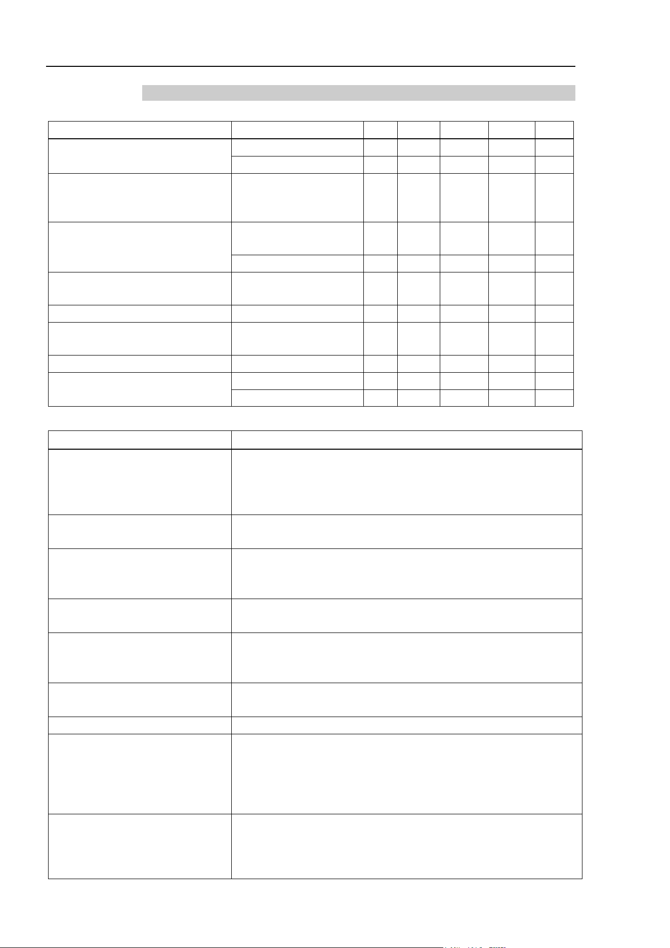
Regular Inspection 1. Regular Inspection for T3-B T6-B Manipulator
146 T-B series Rev.6
1.1.2 Inspection Point
Inspection Item
Inspection Point
Inspection Place
Daily
Monthly
Quarterly
Biannual
Annual
Check looseness or backlash of
bolts/screws.
End effector mounting bolts √ √ √ √ √
Manipulator mounting bolts
√
√
√
√
√
Check looseness of connectors.
External connectors on
Manipulator (on the
connector plates etc.)
√ √ √ √ √
Visually check for external defects.
Clean up if necessary.
External appearance of
Manipulator
√ √ √ √ √
External cables - √ √ √ √
Check for bends or improper location.
Repair or place it properly if necessary.
Safeguard etc. √ √ √ √ √
Check the brake operation Arm #3 √ √ √ √ √
Check whether unusual sound or
vibration occurs.
Whole √ √ √ √ √
Check the power supply behavior. Controller - - - - √
Check behavior of the emergency stop
button and safeguard.
Emergency stop button
-
-
-
-
√
Safeguard - - - - √
Inspection Method
Inspection Point
Inspection Method
Check looseness or backlash of
bolts/screws.
Use a hexagonal wrench to check that the end effector mounting bolts and
the Manipulator mounting bolts are not loose.
When the bolts are loose, refer to “
1.4 Tightening Hexagon Socket Head
Bolts” and tighten them to the proper torque.
Check looseness of connectors.
Check that connectors are not loose.
When the connectors are loose, reattach it not to come off.
Visually check for external defects.
Clean up if necessary.
Check the appearance of the Manipulator and clean up if necessary.
Check the appearance of the cable, and if it is scratched, check that there is
no cable disconnection.
Check for bends or improper location.
Repair or place it properly if necessary.
Check that the safeguard, etc. are located properly.
If the location is improper, place it properly.
Check the brake operation
Check that the shaft does not fall when in MOTOR OFF.
If the shaft falls when in MOTOR OFF and the brake is not released, contact
the supplier.
Check whether unusual sound or
vibration occurs.
Check that there is no unusual sound or vibration when operating.
If there is something wrong, contact the supplier.
Check the power supply behavior. Turn OFF and ON the power supply, and check that it starts without any error.
Check behavior of the emergency stop
button
Operate emergency stop switch with the motor energized, then check the
LED lamp on the top of
the power unit lights off and the ESTOP LED on the
Controller lights up.
If EPSON RC+ is connected, make sure to check “EStop” is displayed in red
on the status bar.
Check behavior of the safeguard.
Operate safeguard with the motor energized, then check
the LED lamp on
the top of the power unit lights off.
If EPSON RC+ is connected, make sure to check “Safety” is displayed in blue
on the status bar.
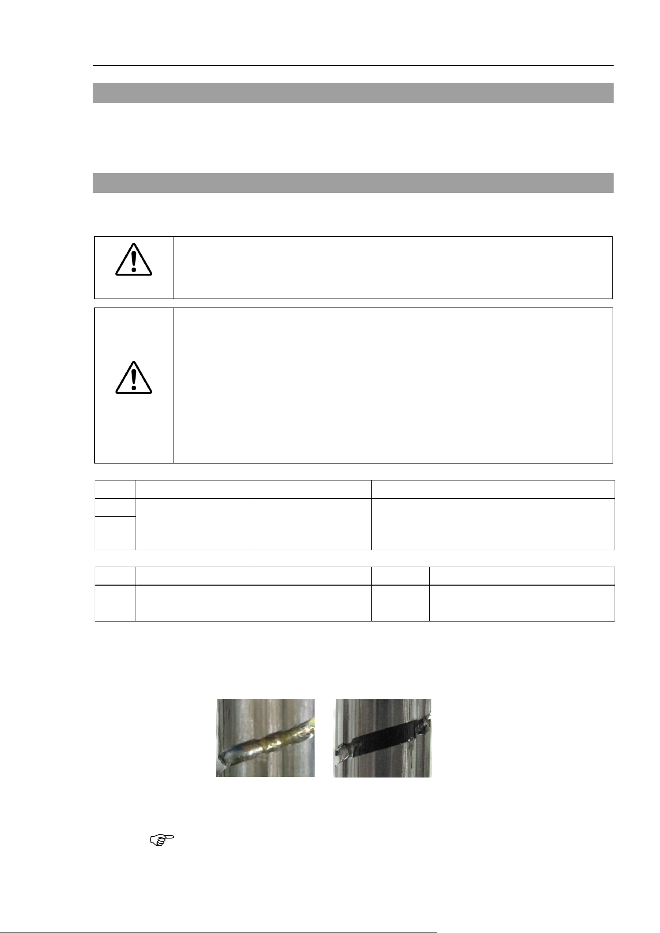
Regular Inspection 1. Regular Inspection for T3-B T6-B Manipulator
T-B series Rev.6 147
1.2 Overhaul (Parts Replacement)
Overhaul (replacement) shall be performed by personnel who has taken a proper training.
For details, refer to “Safety Manual Training”.
For details on overhaul, refer to the “Maintenance Manual”.
1.3 Greasing
The ball screw spline and reduction gear units need greasing regularly. Only use the grease
specified in the following table.
CAUTION
■
Keep enough grease in the Manipulator. Operating the Manipulator with
insufficient
grease will damage sliding parts and/or result in insufficient function of
the Manipulator
. Once the parts are damaged, a lot of time and money will be
required for the repairs.
CAUTION
■
If grease gets into your eyes, mouth, or on your skin, follow the instructions below.
If grease gets into your eyes
: Flush them thoroughly with clean water, and then see a doctor
immediately.
If grease gets into your mouth
: If swallowed, do not induce vomiting. See a doctor immediately.
: If grease just gets into your mouth, wash out your mouth with water
thoroughly.
If grease gets on your skin
: Wash the area thoroughly with soap and water.
Greasing part
Greasing Interval
Notice
Joint #1
Reduction gear units Overhaul timing
Greasing
shall be performed by personnel who has
taken a proper training.
For details, “T-B series Maintenance Manual”
Joint #2
Greasing part
Greasing Interval
Grease
How to grease
Joint #3 Ball screw spline unit
At 100 km of operation
(50 km for first greasing)
AFB
Greasing the Ball Screw Spline Unit
(See below)
Joint #3 Ball screw spline unit
The recommended greasing interval is at 100 km of operation. However, greasing timing
also can be checked from the grease condition. Perform greasing if the grease is
discolored or becomes dry.
Normal grease Discolored grease
Perform greasing at 50 km of operation for the first time of greasing.
For the EPSON RC+ 7.0 the recommended replacement time for the grease on the ball screw
spline unit can be checked in the [Maintenance] dialog box.
Reference: T-B series Maintenance Manual 4. Alarm
NOTE
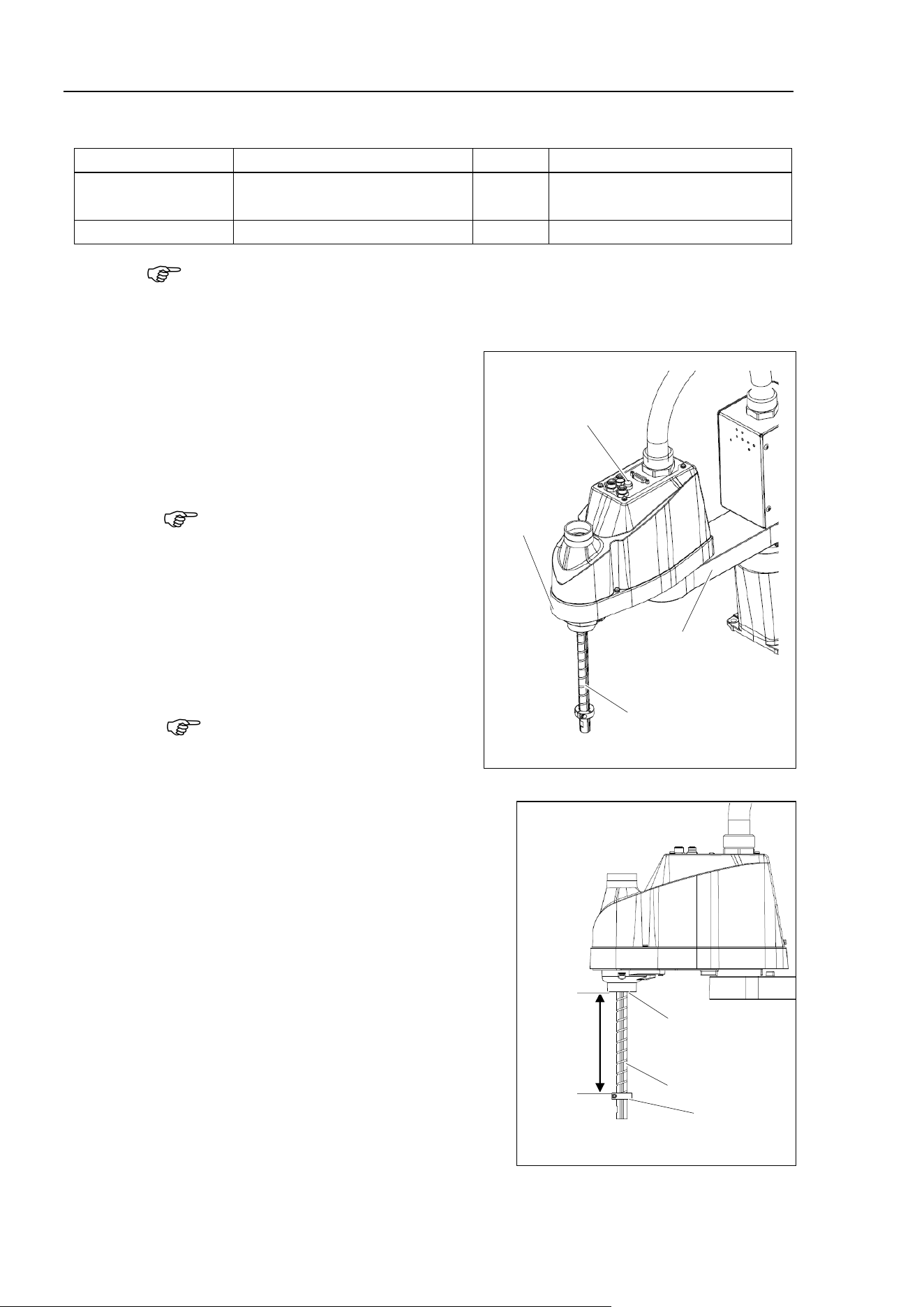
Regular Inspection 1. Regular Inspection for T3-B T6-B Manipulator
148 T-B series Rev.6
Greasing the Ball Screw Spline Unit
Name
Quantity
NOTE
Grease
For Ball Screw Spline Unit
(AFB grease)
Proper
quantity
Tools
Wiping cloth
1
For wiping grease (Spline shaft)
Cover the surrounding area such as the end effector and peripheral equipment in case the
grease drips.
(1)
Turn ON the Manipulator.
(2)
Move the shaft to its lower limit in one
of the following methods.
-
Move the shaft to its lower limit
manually while pressing the brake
release switch.
Be careful of the shaft falling and
rotating while the brake release switch is
being pressed because the shaft may be
lowered by the weight of the end
effector.
- Move the shaft to its lower limit from
EPSON RC+ 7.0 [Tools]-[Robot
Manager]-[Jog & Teach].
Make sure that the hand does not
interfere with peripheral equipment.
Joint #3
Brake release switch
Arm #1
Arm #2
Shaft
(Illustration T3-B401S)
(3)
Turn OFF the Manipulator.
(4)
Wipe off the old grease from the shaft, and
then apply new grease to it.
G
rease application range is from the end of
the spline nut to mechanical stop.
Grease
application
range
Shaft
End of spline nut
Mechanical stop
(Illustration T3-B401S)
NOTE
NOTE
NOTE
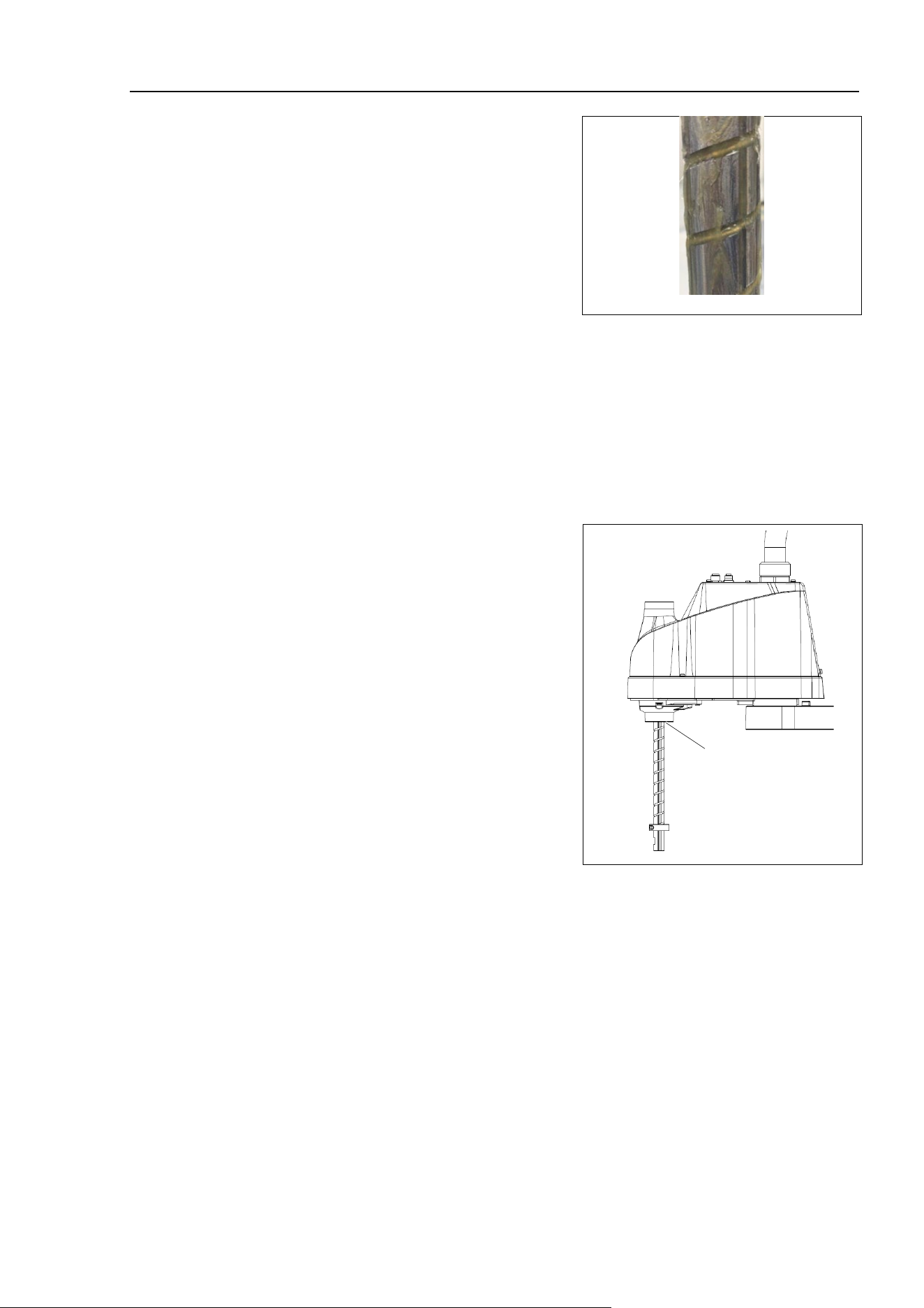
Regular Inspection 1. Regular Inspection for T3-B T6-B Manipulator
T-B series Rev.6 149
(5)
Apply grease evenly to the spiral groove of
the ball screw spline unit and the vertical
groove so that the groove is filled.
Grease application example
(6)
Turn ON the Manipulator.
(7)
Start the robot manager and move the shaft to the origin position. Be careful not to hit
peripheral equipment.
(
8) After moving to the origin position, reciprocate the shaft. The reciprocating operation is
a low power mode operation program that performs from the upper limit to the lower
limit. Run for about 5 minutes to spread the grease over the shaft.
(
9) Turn OFF the Manipulator.
(
10)
W
ipe off excess grease on the end of the
spline nut and mechanical stop.
End of spline nut
(Illustration T3-B401S)
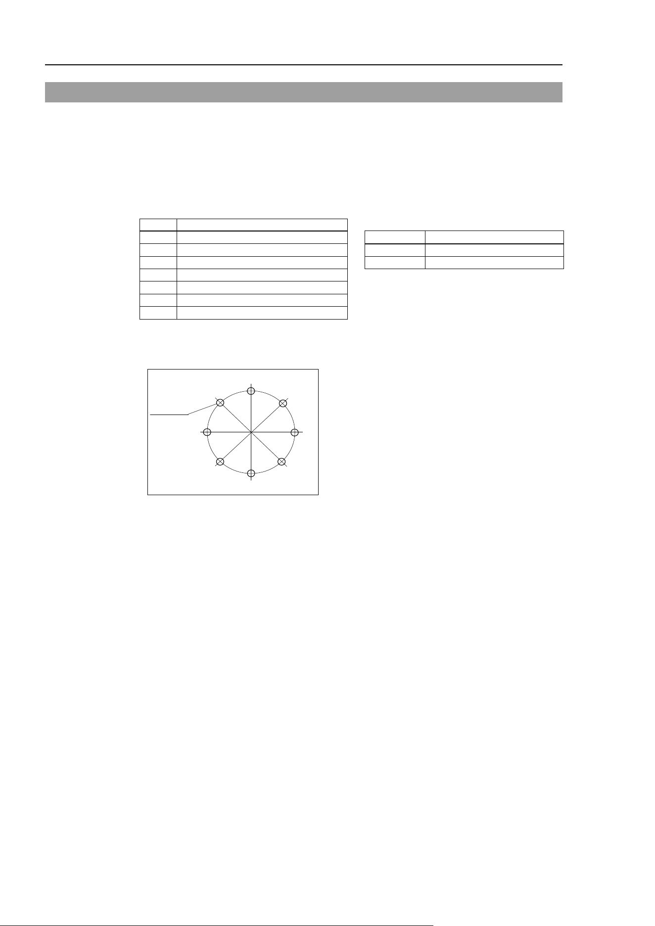
Regular Inspection 1. Regular Inspection for T3-B T6-B Manipulator
150 T-B series Rev.6
1.4 Tightening Hexagon Socket Head Cap Bolts
Hexagon socket head cap bolts (herein after referred to as bolt) are used in places where
mechanical strength is required. These bolts are fastened with the tightening torques
shown in the following table.
When it is necessary to refasten these bolts in some procedures in this manual (except special
cases as noted), use a torque wrench so that the bolts are fastened with the appropriate
tightening torques as shown below.
Bolt
Tightening Torque
Refer below for the set screw.
M3
2.0 ± 0.1 N⋅m
(21 ± 1 kgf⋅cm)
Set Screw
Tightening Torque
M4
4.0 ± 0.2 N⋅m
(41 ± 2 kgf⋅cm)
M4
2.4 ± 0.1 N⋅m
(26 ± 1 kgf⋅cm)
M5
8.0 ± 0.4 N⋅m
(82 ± 4 kgf⋅cm)
M5
4.0 ± 0.2 N⋅m
(41 ± 2 kgf⋅cm)
M6
13.0 ± 0.6 N⋅m
(133 ± 6 kgf⋅cm)
M8
32.0 ± 1.6 N⋅m
(326 ± 16 kgf⋅cm)
M10
58.0 ± 2.9 N⋅m
(590 ± 30 kgf⋅cm)
M12
100.0 ± 5.0 N⋅m
(1,020 ± 51 kgf⋅cm)
The bolts aligned on a circumference should be fastened in a crisscross pattern as shown in
the figure below.
1
5
3
7
2
6
4
8
Bolt hole
Do not fasten all bolts securely at one time. Divide
the number of times that the bolts are fastened into
two or three and fasten the bolts securely with a
hexagonal wrench. Then, use a torque wrench so
that the bolts are fastened with tightening torques
shown in the table above.

151
Appendix
This volume describes the specifications table for each model and detailed data of stopping time
and stopping distance.


Appendix A: Specifications
T-B series Rev.6 153
Appendix A: Specifications
T3-B Specifications
Item
T3-B401S
Arm length
Arm #1, #2
400 mm
Arm #1
225 mm
Arm #2
175 mm
Weight (cables not included)
Approx. 14 kg: 31 lbs.
Driving method
All joints
AC servo motor
Max.
operating speed*1
Joints #1, #2
3700 mm/s
Joint #3
1000 mm/s
Joint #4
2600 °/s
Repeatability
Joints #1, #2
± 0.02 mm
Joint #3
± 0.02 mm
Joint #4
± 0.02°
Max. motion range
Joint #1
± 132°
Joint #2
± 141°
Joint #3
150 mm
Joint #4
± 360°
Max. pulse range
Joint #1
− 95574 ~ 505174
Joint #2
± 320854
Joint #3
− 187734 ~ 0
Joint #4
± 74130
Resolution
Joint #1
0.000439°/pulse
Joint #2
0.000439°/pulse
Joint #3
0.000799 mm/pulse
Joint #4
0.004857°/pulse
Motor rated capacity
Joint #1
200 W
Joint #2
100 W
Joint #3
100 W
Joint #4
100 W
Payload (Load)
Rated
1 kg
Max.
3 kg
Joint #4 allowable
moment of inertia*2
Rated
0.003 kg·m
2
Max.
0.01 kg·m
2
Hand
Shaft diameter
ø 16 mm
Through hole
ø 11 mm
Joint #3 down force
83 N
Hand I/O connector
15 pin: D-sub
Installed pneumatic tube for customer use
2 pneumatic tubes (ø6 mm): 0.59 MPa (6 kgf/cm
2
: 86 psi)
1 pneumatic tubes (ø4 mm): 0.59 MPa (6 kgf/cm
2
: 86 psi)
Mounting hole
120 × 120 mm
4-M8
Environmental
requirements
Ambient temp.
5 to 40 °C *3
Ambient relative
humidity
20 to 80% (no condensation)
Noise level *4
L
Aeq
= 70 dB (A) or under

Appendix A: Specifications
154 T-B series Rev.6
Item
T3-B401S
Assignable
value
( ) Default
value
Speed
1 ~ (5) ~ 100
Accel *5
1 ~ (10) ~ 120
SpeedS
0.1 ~ (50) ~ 2000
AccelS
0.1 ~ (200) ~ 10000
Fine
0 ~ (1250) ~ 65535
Weight
0,175 ~ (1,175) ~ 3,175
Motion control
Development environment
EPSON RC+ 7.0
Programming language
SPEL+ (multi-tasking robot language)
Joint control
Standard 4 joints simultaneous control
Digital AC servo control
Positioning control
PTP (Point-To-Point control)
CP (Continuous Path control)
Speed control
PTP motion : Programmable in the range of
1 to 100%
CP motion : Programmable (Actual value to be
manually entered.)
Acceleration/Deceleration
control
PTP motion : Programmable in the range of
1 to 100%; Automatic
CP motion : Programmable (Actual value to be
manually entered.)
External
interface
EMERGENCY
EMERGENCY STOP:
Redundant (Category 3) Supported for
internal/external power supply
Safeguard System:
Redundant (Category 3) Supported for external
power supply
I/O
Standard I/O
(Rear side of Manipulator)
Input: 18 points
Output: 12 points
Non-polar, Supported for both Sink and Source
Remote I/O
(Remote functions
are applied to
Standard I/O)
Input: 8 points
Program, 3 points
Start, Stop, Pause, Continue, Reset
Output: 8 points
Ready, Running, Paused, Error, SafeguardOn,
SError, Warning, EStopOff
Hand I/O
(Upper side of Arm #2)
Input: 6 points
Output: 4 points
Non-polar, Supported for both Sink and Source
Power: 24V Max. 500mA
External
interface
Field bus slave (option)
Input: 256 points
Output: 256 points
Enable to add only one more module
TP connection port
Supported for teach pendant (Option: TP2, TP3)
PC connection port
USB B connector
Supported for USB 2.0 High Speed / Full Speed
USB memory connection port
USB A connector
Supported for USB 2.0 High Speed / Full Speed
Ethernet port
Supported for 10/100 Mbps
Available up to 8 ports
RESET switch
Enable to use for resetting of system
Display Mode display LED
TEACH, AUTO, PROGRAM, TestMode, Error,
E-STOP

Appendix A: Specifications
T-B series Rev.6 155
Item
T3-B401S
Controller status save
Save to USB memory
Save in RC+ (PC)
Voltage
100 V to 240 VAC
Phase
Single phase
Frequency
50 / 60 Hz
Momentary power interrupt
Less than 10 ms
Power consumption
660 VA
Inrush current
(When AC power is turned
ON)
Max. 30A (Less than 2 ms.)
Short-circuit current rating
5.0 kA
Max. load current
3.3 A
Leak current
Max. 10 mA
Ground resistance
Less than 100Ω
Safety standard
CE Marking
EMC Directive, Machinery Directive, RoHS Directive
UKCA Marking
EMC Regulations, Machinery Regulations, RoHS Regulations
KC Marking, KCs Marking
*1: In the case of PTP command. Maximum operating speed for CP command is 2000 mm/s on horizontal
plane.
*2: In the case where the center of gravity is at the center of Joint #4.
If the center of gravity is not at the center of Joint #4, set the parameter using Inertia command.
*3: When the product is used in a low temperature environment around the minimum temperature of the product
specification, or when the product is suspended for a long time on holidays or at night, a collision detection
error may occur due to the large resistance of the drive unit immediately after the start of operation. In such
a case, it is recommended to warm up for about 10 minutes.
*4: Conditions of Manipulator during measurement as follows:
Operating conditions : Under rated load, 4-joints simultaneous motion, maximum speed, maximum
acceleration/deceleration, and duty 50%.
Measurement point : Rear of the Manipulator, 1000 mm apart from the motion range, 50 mm above the
base-installed surface.
*5: In general use, Accel setting 100 is the optimum setting that maintains the balance of acceleration and
vibration when positioning. Although values larger than 100 can be set to Accel, it is recommended to
minimize the use of large values to necessary motions since operating the manipulator continuously with
the large Accel setting may shorten the product life remarkably.

Appendix A: Specifications
156 T-B series Rev.6
T6-B Specifications
Item
T6-B602S
Arm length
Arm #1, #2
600 mm
Arm #1
325 mm
Arm #2
275 mm
Weight (cables not included)
Approx. 21 kg: 46 lbs.
Driving method
All joints
AC servo motor
Max.
operating speed*1
Joints #1, #2
4180 mm/s
Joint #3
1000 mm/s
Joint #4
1800 °/s
Repeatability
Joints #1, #2
± 0.04 mm
Joint #3
± 0.02 mm
Joint #4
± 0.02°
Max. motion range
Joint #1
± 132°
Joint #2
± 150°
Joint #3
200 mm
Joint #4
± 360°
Max. pulse range
Joint #1
− 152918 ~ 808278
Joint #2
± 341334
Joint #3
− 245760 ~ 0
Joint #4
± 245760
Resolution
Joint #1
0.000275°/pulse
Joint #2
0.000439°/pulse
Joint #3
0.000814 mm/pulse
Joint #4
0.001465°/pulse
Motor rated capacity
Joint #1
300 W
Joint #2
200 W
Joint #3
100 W
Joint #4
100 W
Payload (Load)
Rated
2 kg
Max.
6 kg
Joint #4 allowable
moment of inertia*2
Rated
0.01 kg·m
2
Max.
0.08 kg·m
2
Hand
Shaft diameter
ø 20 mm
Through hole
ø 14 mm
Joint #3 down force
83 N
Hand I/O connector
15 pin: D-sub
Installed pneumatic tube for customer use
2 pneumatic tubes (ø6 mm): 0.59 MPa (6 kgf/cm
2
: 86 psi)
1 pneumatic tubes (ø4 mm): 0.59 MPa (6 kgf/cm
2
: 86 psi)
Mounting hole
150 × 150 mm
4-M8
Environmental
requirements
Ambient temp.
5 ~ 40 °C *3
Ambient relative
humidity
20 ~ 80 % (no condensation)
Noise level *4
L
Aeq
= 70 dB (A) or under

Appendix A: Specifications
T-B series Rev.6 157
Item
T6-B602S
Assignable
value
( ) Default
value
Speed
1 ~ (5) ~ 100
Accel *5
1 ~ (10) ~ 120
SpeedS
0.1 ~ (40) ~ 2000
AccelS
0.1 ~ (200) ~ 10000
Fine
0 ~ (1250) ~ 65535
Weight
0,275 ~ (2,275) ~ 6,275
Motion control
Development environment
EPSON RC+ 7.0
Programming language
SPEL+ (multi-tasking robot language)
Joint control
Standard 4 joints simultaneous control
Digital AC servo control
Positioning control
PTP (Point-To-Point control)
CP (Continuous Path control)
Speed control
PTP motion : Programmable in the range of 1 to
100%
CP motion : Programmable (Actual value to be
manually entered.)
Acceleration/Deceleration
control
PTP motion : Programmable in the range of 1 to
100%; Automatic
CP motion : Programmable (Actual value to be
manually entered.)
External
interface
EMERGENCY
EMERGENCY STOP:
Redundant (Category 3) Supported for
internal/external power supply
Safeguard System:
Redundant (Category 3) Supported for external
power supply
I/O
Standard I/O
(Rear side of Manipulator)
Input: 18 points
Output: 12 points
Non-polar, Supported for both Sink and Source
Remote I/O
(Remote functions
are applied to
Standard I/O)
Input: 8 points
Program, 3 points
Start, Stop, Pause, Continue, Reset
Output: 8 points
Ready, Running, Paused, Error, SafeguardOn,
SError, Warning, EStopOff
Hand I/O
(Upper side of Arm #2)
Input: 6 points
Output: 4 points
Non-polar, Supported for both Sink and Source
Power: 24V Max. 700mA
External
interface
Field bus slave (option)
Input: 256 points
Output: 256 points
Enable to add only one more module
TP connection port
Supported for teach pendant (Option: TP2, TP3)
PC connection port
USB B connector
Supported for USB 2.0 High Speed / Full Speed
USB memory connection port
USB A connector
Supported for USB 2.0 High Speed / Full Speed
Ethernet port
Supported for 10/100 Mbps
Available up to 8 ports
RESET switch
Enable to use for resetting of system
Display Mode display LED
TEACH, AUTO, PROGRAM, TestMode, Error,
E-STOP

Appendix A: Specifications
158 T-B series Rev.6
Item
T6-B602S
Controller status save
Save to USB memory
Save in RC+ (PC)
Voltage
100 V to 240 VAC
Phase
Single phase
Frequency
50 / 60 Hz
Momentary power interrupt
Less than 10 ms
Power consumption
1,200 VA
Inrush current
(When AC power is turned
ON)
Max. 60A (Less than 2 ms.)
Short-circuit current rating
5.0 kA
Max. load current
6.0 A
Leak current
Max. 10 mA
Ground resistance
Less than 100Ω
Safety standard
CE Marking
EMC Directive, Machinery Directive, RoHS Directive
UKCA Marking
EMC Regulations, Machinery Regulations, RoHS Regulations
KC Marking, KCs Marking
*1: In the case of PTP command. Maximum operating speed for CP command is 2000 mm/s on horizontal
plane.
*2: In the case where the center of gravity is at the center of Joint #4.
If the center of gravity is not at the center of Joint #4, set the parameter using Inertia command.
*3: When the product is used in a low temperature environment around the minimum temperature of the product
specification, or when the product is suspended for a long time on holidays or at night, a collision detection
error may occur due to the large resistance of the drive unit immediately after the start of operation. In such
a case, it is recommended to warm up for about 10 minutes.
*4: Conditions of Manipulator during measurement as follows:
Operating conditions : Under rated load, 4-joints simultaneous motion, maximum speed, maximum
acceleration/deceleration, and duty 50%.
Measurement point : Rear of the Manipulator, 1000 mm apart from the motion range, 50 mm above the
base-installed surface.
*5: In general use, Accel setting 100 is the optimum setting that maintains the balance of acceleration and
vibration when positioning. Although values larger than 100 can be set to Accel, it is recommended to
minimize the use of large values to necessary motions since operating the manipulator continuously with
the large Accel setting may shorten the product life remarkably.
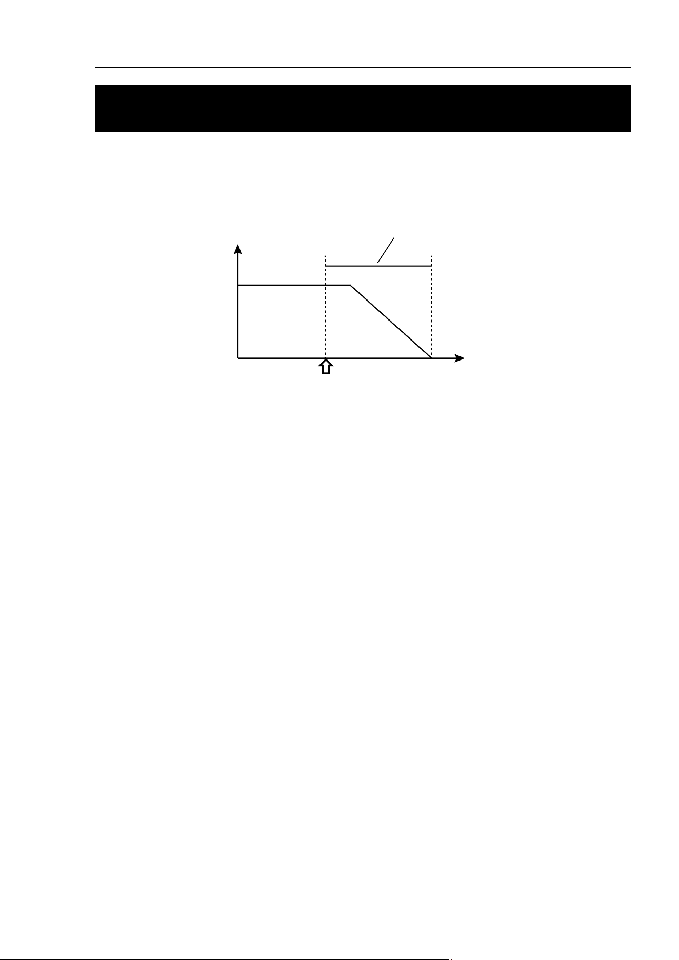
Appendix B: Stopping time and Stopping distance in Emergency
T-B series Rev.6 159
Appendix B: Stopping time and Stopping distance in
Emergency
The stopping time and stopping distance in emergency stop are shown in a graph for each
model.
The stopping time is “Stopping time” in the figure below. Be sure to confirm that safety is
ensured according to the installation environment and operation of the robot.
Motor speed
Stopping time
Time
In emergency stop
or safeguard is opened
Condition:
The stopping time and stopping distance vary depending on the parameters (setting value)
set for the robot. In this chapter, the time and distance are shown with the following
parameters.
Accel : 100 ,100
Other : Default
Description of legend:
The graph is shown for each Weight value (rated value, 100%, about 66%, and about 33%
of the maximum payload).
Horizontal axis : Arm speed (Speed value)
Vertical axis : Stopping time and stopping distance in each arm speed
Time [sec] : Stopping time
Distance [deg] : Stopping distance of J1 and J2
Distance [mm] : Stopping distance of J3
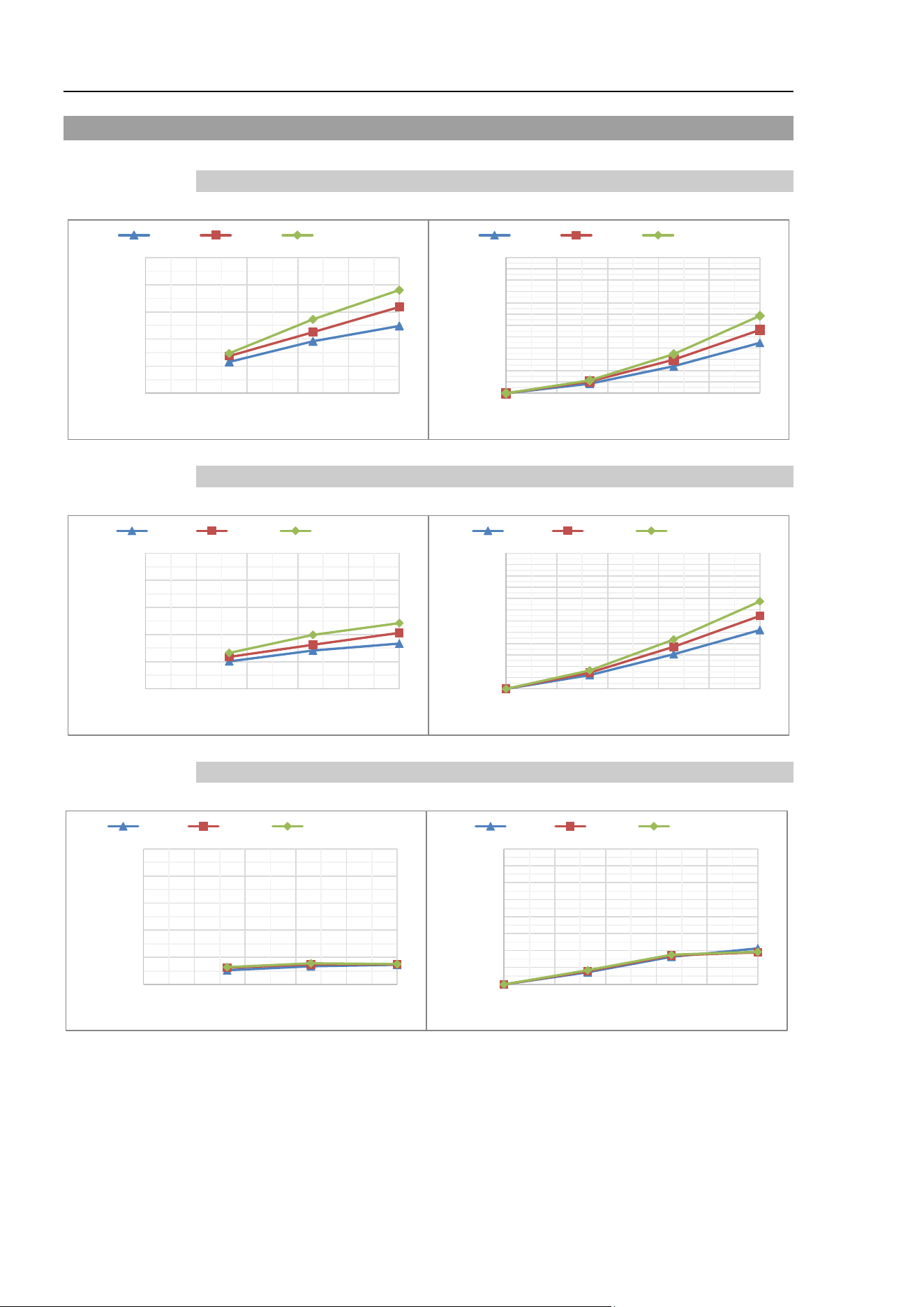
Appendix B: Stopping time and Stopping distance in Emergency
160 T-B series Rev.6
T3-B Stopping time and Stopping distance in Emergency
T3-B401S: J1
T3-B401S: J2
T3-B401S: J3
0.00
0.10
0.20
0.30
0.40
0.50
0% 20% 40% 60% 80% 100%
Time[sec]
Speed[%]
J1
1.0kg 2.0kg 3.0kg
Weight[kg]
0.0
10.0
20.0
30.0
40.0
50.0
60.0
70.0
80.0
90.0
100.0
110.0
120.0
0% 20% 40% 60% 80% 100%
Distance[deg]
Speed[%]
J1
1.0kg 2.0kg 3.0kg
Weight[kg]
0.00
0.10
0.20
0.30
0.40
0.50
0% 20% 40% 60% 80% 100%
Time[sec]
Speed[%]
J2
1.0kg 2.0 kg 3.0 kg
Weight[kg]
0.0
10.0
20.0
30.0
40.0
50.0
60.0
70.0
80.0
90.0
100.0
110.0
120.0
0% 20% 40% 60% 80% 100%
Distance[deg]
Speed[%]
J2
1.0kg 2.0 kg 3.0 kg
Weight[kg]
0.00
0.10
0.20
0.30
0.40
0.50
0% 20% 40% 60% 80% 100%
Time[sec]
Speed[%]
J3
1.0kg 2.0 kg 3.0 kg
Weight[kg]
0.0
20.0
40.0
60.0
80.0
100.0
120.0
140.0
160.0
0% 20% 40% 60% 80% 100%
Distance[mm]
Speed[%]
J3
1.0kg 2.0 kg 3.0 kg
Weight[kg]
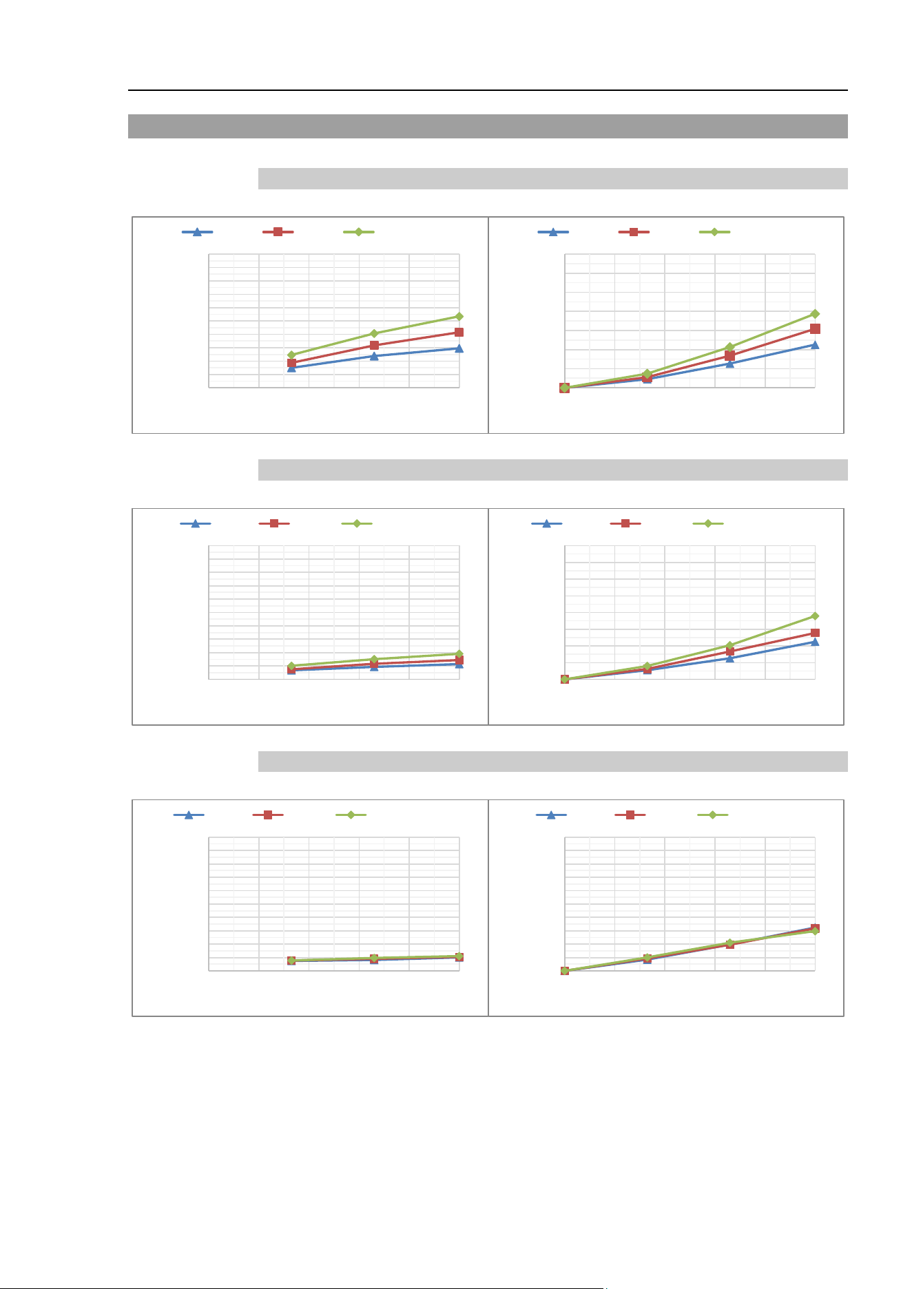
Appendix B: Stopping time and Stopping distance in Emergency
T-B series Rev.6 161
T6-B Stopping time and Stopping distance in Emergency
T6-B602S: J1
T6-B602S: J2
T6-B602S: J3
0.00
0.10
0.20
0.30
0.40
0.50
0.60
0.70
0.80
0.90
1.00
0% 20% 40% 60% 80% 100%
Time[sec]
Speed[%]
J1
2.0kg 4.0kg 6.0kg
Weight[kg]
0.0
20.0
40.0
60.0
80.0
100.0
120.0
140.0
0% 20% 40% 60% 80% 100%
Distance[deg]
Speed[%]
J1
2.0kg 4.0kg 6.0kg
Weight[kg]
0.00
0.10
0.20
0.30
0.40
0.50
0.60
0.70
0.80
0.90
1.00
0% 20% 40% 60% 80% 100%
Time[sec]
Speed[%]
J2
2.0kg 4.0 kg 6.0 kg
Weight[kg]
0.0
10.0
20.0
30.0
40.0
50.0
60.0
70.0
80.0
0% 20% 40% 60% 80% 100%
Distance[deg]
Speed[%]
J2
2.0kg 4.0 kg 6.0 kg
Weight[kg]
0.00
0.10
0.20
0.30
0.40
0.50
0.60
0.70
0.80
0.90
1.00
0% 20% 40% 60% 80% 100%
Time[sec]
Speed[%]
J3
2.0kg 4.0 kg 6.0 kg
Weight[kg]
0.0
20.0
40.0
60.0
80.0
100.0
120.0
140.0
160.0
180.0
200.0
0% 20% 40% 60% 80% 100%
Distance[mm]
Speed[%]
J3
2.0kg 4.0 kg 6.0 kg
Weight[kg]
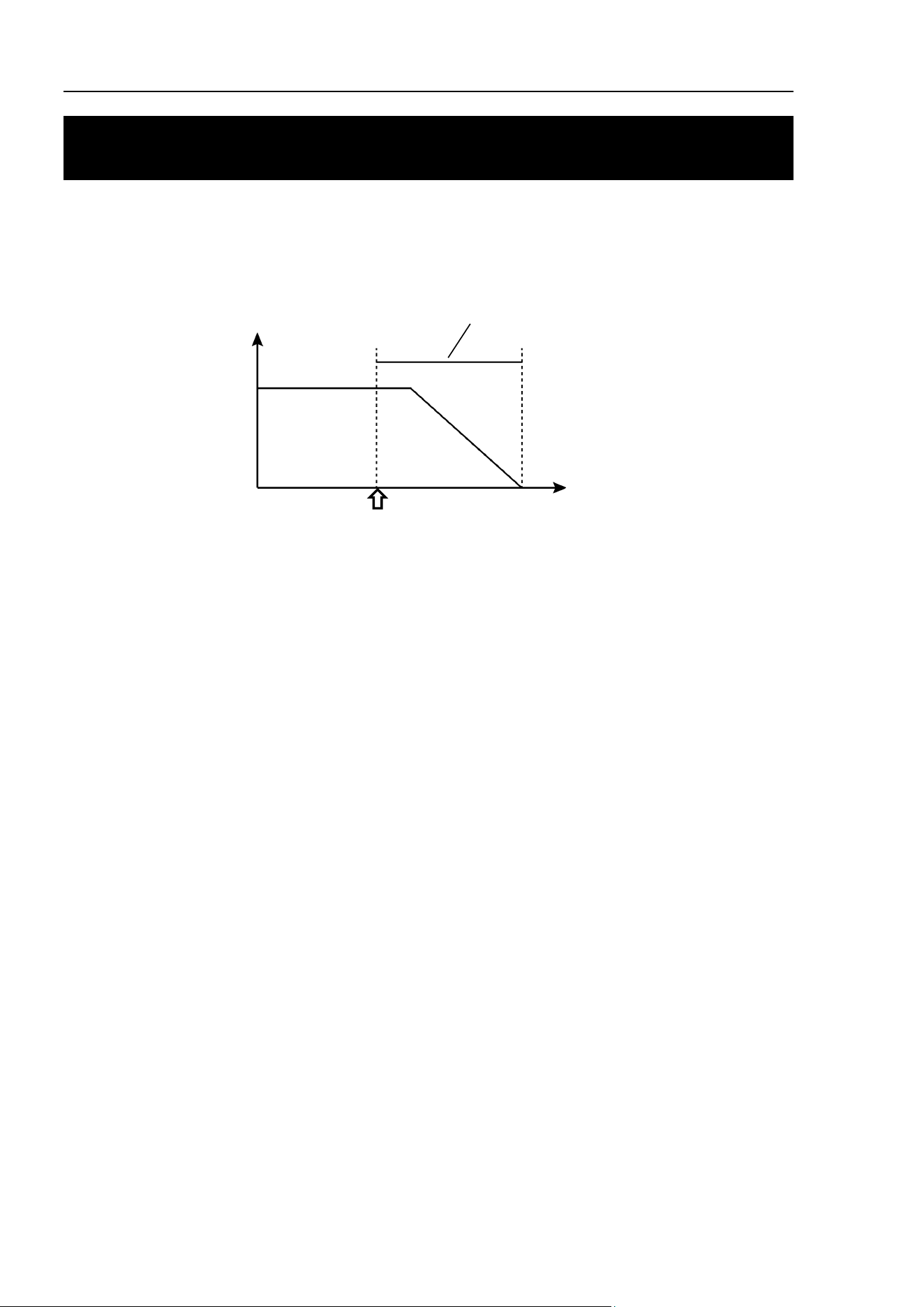
Appendix C: Stopping time and Stopping distance When Safeguard Is Opened
162 T-B series Rev.6
Appendix C: Stopping time and Stopping distance When
Safeguard Is Opened
The stopping time and stopping distance when safeguard is opened are shown in a graph for
each model.
The stopping time is “Stopping time” in the figure below. Be sure to confirm that safety is
ensured according to the installation environment and operation of the robot.
Motor speed
Stopping time
Time
In emergency stop
or safeguard is opened
Condition:
The stopping time and stopping distance vary depending on the parameters (setting value)
set for the robot. In this chapter, the time and distance are shown with the following
parameters.
Accel : 100 ,100
Other : Default
Description of legend:
The graph is shown for each Weight value (rated value, 100%, about 66%, and about 33%
of the maximum payload).
Horizontal axis : Arm speed (Speed value)
Vertical axis : Stopping time and stopping distance in each arm speed
Time [sec] : Stopping time
Distance [deg] : Stopping distance of J1 and J2
Distance [mm] : Stopping distance of J3
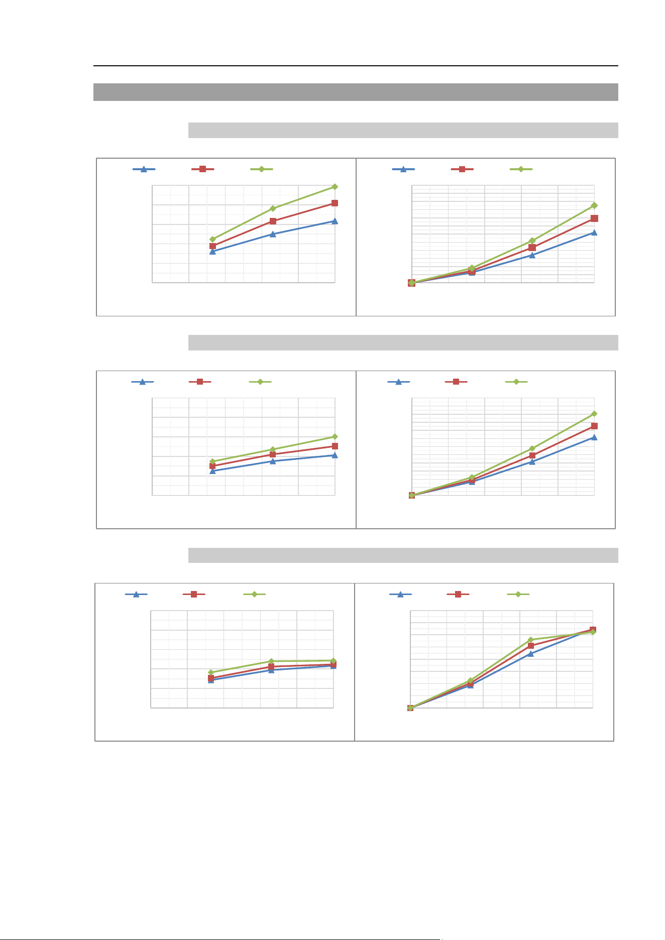
Appendix C: Stopping time and Stopping distance When Safeguard Is Opened
T-B series Rev.6 163
T3-B Stopping time and Stopping distance When Safeguard Is Opened
T3-B401S: J1
T3-B401S: J2
T3-B401S: J3
0.00
0.10
0.20
0.30
0.40
0.50
0% 20% 40% 60% 80% 100%
Time[sec]
Speed[%]
J1
1.0kg 2.0kg 3.0kg
Weight[kg]
0.0
10.0
20.0
30.0
40.0
50.0
60.0
70.0
80.0
90.0
100.0
110.0
120.0
0% 20% 40% 60% 80% 100%
Distance[deg]
Speed[%]
J1
1.0kg 2.0kg 3.0kg
Weight[kg]
0.00
0.10
0.20
0.30
0.40
0.50
0% 20% 40% 60% 80% 100%
Time[sec]
Speed[%]
J2
1.0kg 2.0 kg 3.0 kg
Weight[kg]
0.0
10.0
20.0
30.0
40.0
50.0
60.0
70.0
80.0
90.0
100.0
110.0
120.0
0% 20% 40% 60% 80% 100%
Distance[deg]
Speed[%]
J2
1.0kg 2.0 kg 3.0 kg
Weight[kg]
0.00
0.10
0.20
0.30
0.40
0.50
0% 20% 40% 60% 80% 100%
Time[sec]
Speed[%]
J3
1.0kg 2.0 kg 3.0 kg
Weight[kg]
0.0
20.0
40.0
60.0
80.0
100.0
120.0
140.0
160.0
0% 20% 40% 60% 80% 100%
Distance[mm]
Speed[%]
J3
1.0kg 2.0 kg 3.0 kg
Weight[kg]
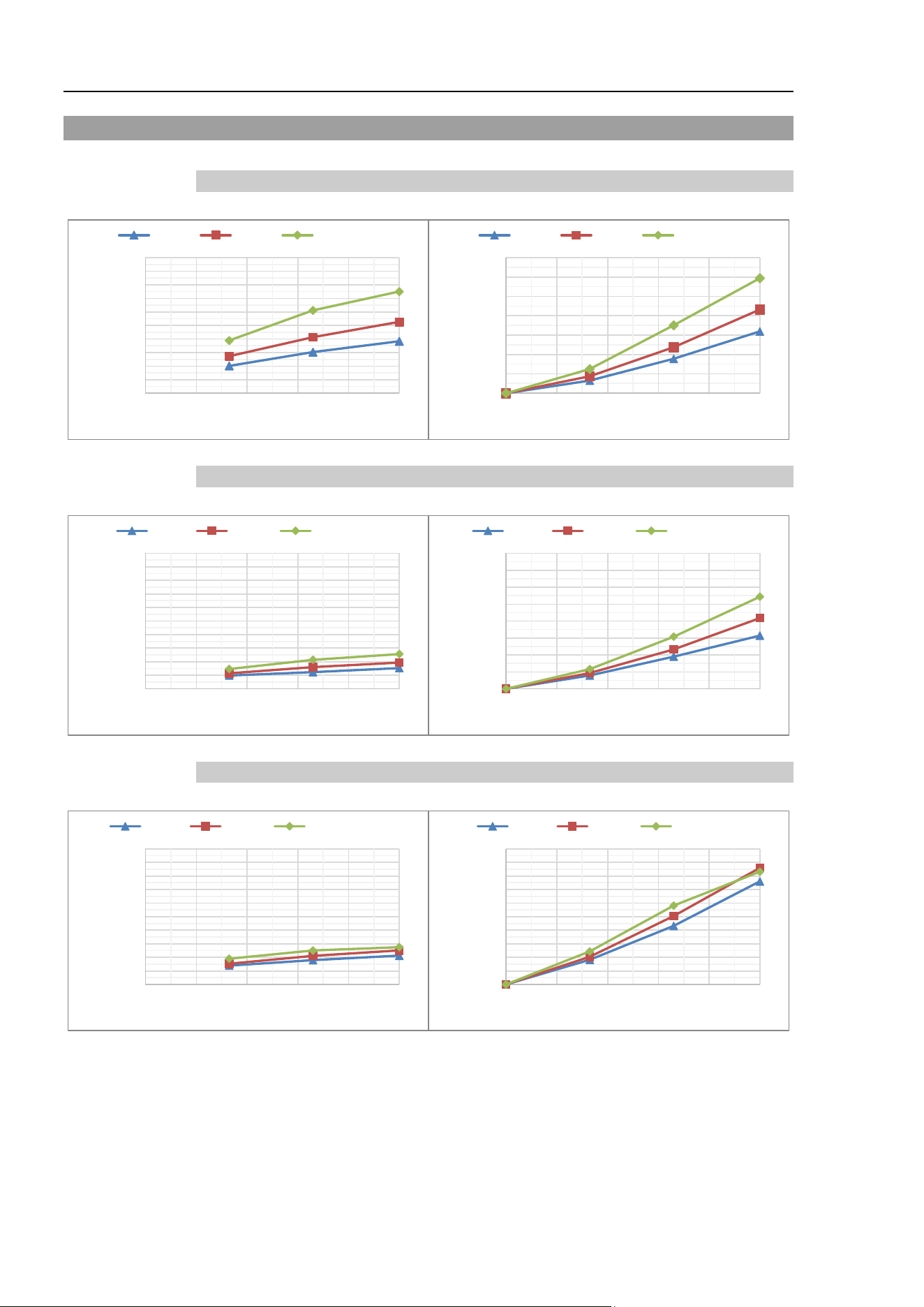
Appendix C: Stopping time and Stopping distance When Safeguard Is Opened
164 T-B series Rev.6
T6-B Stopping time and Stopping distance When Safeguard Is Opened
T6-B602S: J1
T6-B602S: J2
T6-B602S: J3
0.00
0.10
0.20
0.30
0.40
0.50
0.60
0.70
0.80
0.90
1.00
0% 20% 40% 60% 80% 100%
Time[sec]
Speed[%]
J1
2.0kg 4.0kg 6.0kg
Weight[kg]
0.0
20.0
40.0
60.0
80.0
100.0
120.0
140.0
0% 20% 40% 60% 80% 100%
Distance[deg]
Speed[%]
J1
2.0kg 4.0kg 6.0kg
Weight[kg]
0.00
0.10
0.20
0.30
0.40
0.50
0.60
0.70
0.80
0.90
1.00
0% 20% 40% 60% 80% 100%
Time[sec]
Speed[%]
J2
2.0kg 4.0 kg 6.0 kg
Weight[kg]
0.0
10.0
20.0
30.0
40.0
50.0
60.0
70.0
80.0
0% 20% 40% 60% 80% 100%
Distance[deg]
Speed[%]
J2
2.0kg 4.0 kg 6.0 kg
Weight[kg]
0.00
0.10
0.20
0.30
0.40
0.50
0.60
0.70
0.80
0.90
1.00
0% 20% 40% 60% 80% 100%
Time[sec]
Speed[%]
J3
2.0kg 4.0 kg 6.0 kg
Weight[kg]
0.0
20.0
40.0
60.0
80.0
100.0
120.0
140.0
160.0
180.0
200.0
0% 20% 40% 60% 80% 100%
Distance[mm]
Speed[%]
J3
2.0kg 4.0 kg 6.0 kg
Weight[kg]

Appendix D: Open Source Software License
T-B series Rev.6 165
Appendix D: Open Source Software License
(for T-B series)
(1) The T-B series product includes open source software programs listed in Section (9) according to
the license terms of each open source software program.
(2) We provide the source code of the Open Source Programs (each is defined in Section (9)) until five
(5) years after the discontinuation of same model of this option product. If you desire to receive the
source code above, please contact the “SUPPLIER” in the first pages of Safety Manual. You shall
comply with the license terms of each open source software program.
(3) The open source software programs are WITHOUT ANY WARRANTY; without even the implied
warranty of MERCHANTABILITY AND FITNESS FOR A PARTICULAR PURPOSE. See the
license agreements of each open source software program for more details, which are described on
Section (10).
(4) OpenSSL toolkit
The T-B series product includes software developed by the OpenSSL project for use in the
OpenSSL Toolkit (http://www.openssl.org/).
This product includes cryptographic software written by Eric Young (ea[email protected]).
(5) cJSON
This library is available under the MIT License.
Copyright (c) 2009-2017 Dave Gamble and cJSON contributors
https://opensource.org/licenses/mit-license.php
(6) Libxml2
This library is available under the MIT License.
Copyright (C) 1998-2012 Daniel Veillard. All Rights Reserved.
https://opensource.org/licenses/mit-license.php
(7) OPC UA Stack
This module is released under the RCL Licence.
Portions copyright (C) by OPC Foundation, Inc. and licensed under the Reciprocal Community
License (RCL)
https://opcfoundation.org/license/rcl.html
(8) The license terms of each open source software program are described on Section (10).
(9) The list of open source software programs which the T-B series product includes are as follows.
bash dash libc-bin libc6
libcomerr2 libdevmapper 1.02.1
libgcc1 libstdc++6
libudev1 login Logrotate makedev
mount mountall net-tools netbase
rsyslog ssh sudo tzdata
ubuntu-minimal udev Linux Xenomai

Appendix D: Open Source Software License
166 T-B series Rev.6
(10) For the each open source license, please refer to the URLs as follows.
bash http://tiswww.case.edu/php/chet/bash/bashtop.html
dash http://packages.ubuntu.com/ja/precise/dash
libc-bin http://www.eglibc.org/home
libc6 http://www.eglibc.org/home
libcomerr2 http://packages.ubuntu.com/ja/precise/libcomerr2
libdevmapper1.02.1 ftp://sources.redhat.com/pub/lvm2/
libgcc1 ftp://gcc.gnu.org/pub/gcc/releases/
libstdc++6 ftp://gcc.gnu.org/pub/gcc/releases/
libudev0 http://packages.ubuntu.com/ja/precise/libudev0
login http://packages.ubuntu.com/ja/precise/login
logrotate https://fedorahosted.org/logrotate/
makedev ftp.redhat.com
mount ftp://ftp.us.kernel.org/pub/linux/utils/util-linux-ng/
mountall http://packages.ubuntu.com/ja/precise/mountall
net-tools https://developer.berlios.de/projects/net-tools/
netbase http://packages.ubuntu.com/ja/precise/netbase
rsyslog http://www.rsyslog.com
ssh http://www.openssh.com/ftp.html
sudo http://www.sudo.ws/
tzdata http://www.iana.org/time-zones
ubuntu-minimal http://packages.ubuntu.com/ja/precise/ubuntu-minimal
udev http://packages.ubuntu.com/ja/precise/udev
Linux http://www.kernel.org/
Xenomai http://www.xenomai.org/