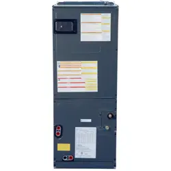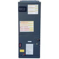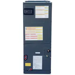
A2L ACCESSORY / ZONING CONTROL KIT
Installation Instructions
IO-7032C
08/2025
Attention Installing Personnel
As a professional installer, you have an obligation to know
the product better than the customer. This includes all
safety precautions and related items.
Prior to the actual installation, thoroughly familiarize
yourself with this instruction manual. Pay special attention
to all safety warnings. Often during installation or repair,
it is possible to place yourself in a position which is more
hazardous than when the unit is in operation.
Remember, it is your responsibility to install the product
safely and to know it well enough to be able to instruct a
customer in its safe use.
Safety is a matter of common sense. A matter of thinking
before acting. Most dealers have a list of specic good
safety practices. Follow them.
The precautions listed in this installation manual are
intended as supplemental to existing practices. However,
if there is a direct conict between existing practices and
the content of this manual, the precautions listed here take
precedence.
If a strain relief is required for wiring, the Zone/Accessory
board can be installed inside a separate electronic
enclosure. Select an enclosure that meets local code
requirements.
Safety Precautions
The following symbols and labels are used throughout this
manual to indicate immediate or potential safety hazards.
It is the owner’s and installer’s responsibility to read
and comply with all safety information and instructions
accompanying these symbols. Failure to heed safety
information increases the risk of personal injury, property
damage, and/or product damage.
WARNING
HIGH VOLTAGE
Disconnect all power before servicing this
unit. Multiple power sources may be present.
Failure to do so may cause property damage,
personal injury or death.
If the installation check, as detailed in these
installation instructions, does not pass successfully,
please call 1-855 DAIKIN1, option 3 for further
assistance.
19001 Kermier Rd., Waller, TX 77484
wwww.daikincomfort.com • www.goodmanmfg.com • www.amana-hac.com
© 2025 Daikin Comfort Technologies Manufacturing, Inc.
is a registered trademark of Maytag Corporation or its related companies
and is used under license. All rights reserved.
WARNING
Do not bypass safety devices.
Only personnel that have been trained to install, adjust,
service, maintenance or repair (hereinafter, “service”)
the equipment specified in this manual should service the
equipment.
This equipment is not intended for use by persons
(including children) with reduced physical, sensory or
mental capacities, or lack of experience and knowledge,
unless they have been given supervision or instruction
concerning use of the appliance by a person responsible
for their safety.
Children should be supervised to ensure that they do not
play with the equipment.
The manufacturer will not be responsible for any injury
or property damage arising from improper supervision,
service or service procedures. If you service this unit, you
assume responsibility for any injury or property damage
which may result. In addition, in jurisdictions that require
one or more licenses to service the equipment specified in
this manual, only licensed personnel should service the
equipment. Improper supervision, installation, adjustment,
servicing, maintenance or repair of the equipment specified
in this manual, or attempting to install, adjust, service
or repair the equipment specified in this manual without
proper supervision or training may result in product
damage, property damage, personal injury or death.
WARNING
Parts needed in kit:
1) 10ft RED 18 AWG wire with insulated ¼” terminals on
each end (for wiring the Alarm terminal to the HVAC
unit)
2) 10ft BLUE 18 AWG wire with insulated ¼” terminal on
one end and cut on the other end (for wiring transformer
common to the HVAC unit)
3) 4 10ft BLACK 18 AWG wires with insulated ¼” terminal
on one end and cut on the other end (for power wiring to
accessory and to accessory power)
4) 4 10ft WHITE 18 AWG wires with insulated ¼” terminal
on one end and cut on the other end (for neutral or
common wiring to accessory and to accessory power)
5) Mounting hardware (screws & wall anchors)
6) PCB Enclosure with Zoning PCB enclosed inside it
The A2L Accessory / Zoning Control is designed to support
R-32 refrigerant HVAC installations that use electronic
accessories such as zoning, electronic air cleaners, UV
2
lamps, humidiers, or dehumidiers. If these types of
electronic accessories are not used in the installation, the
A2L Accessory / Zoning Control is not needed. These
HVAC installations must also contain a refrigerant detection
system to detect leaks. If there is an R-32 refrigerant leak
inside the indoor unit, the system’s refrigerant detection
system will turn o all HVAC functionality (cooling and
heating modes) and ensure the indoor blower is running
to dissipate any R-32 refrigerant gas. The A2L Accesso-
ry / Zoning Control, working with the system’s refrigerant
leak detection system, will make sure all zone dampers
are open and any installed accessory is turned o during
an active refrigerant leak alarm. After the system’s refrig-
erant detection system removes the leak alarm, the A2L
Accessory / Zoning Control will provide power back to any
installed accessory device and no longer hold any damp-
ers in the open position. This manual will explain how to
properly wire the A2L Accessory / Zoning Control to any
installed accessory devices and the HVAC unit’s refrigerant
detection system.
The kit should never be physically mounted anywhere on
the unit. The kit can be mounted to a wall near the unit, on
a wood beam, on the furnace return duct or other locations
deemed acceptable. The kit can be mounted using the
wall anchors and screws provided with the kit. The kit must
always be accessible and serviceable.
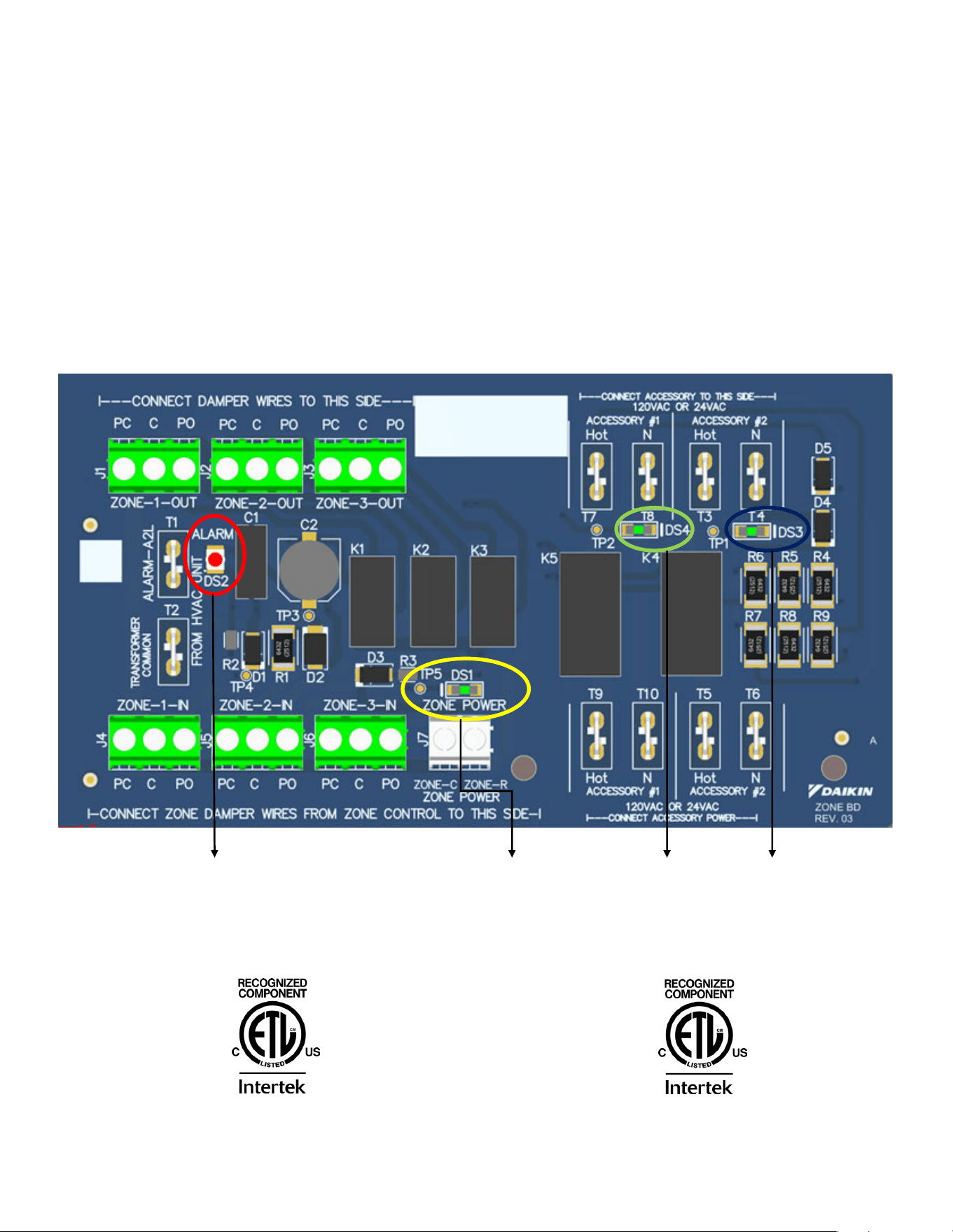
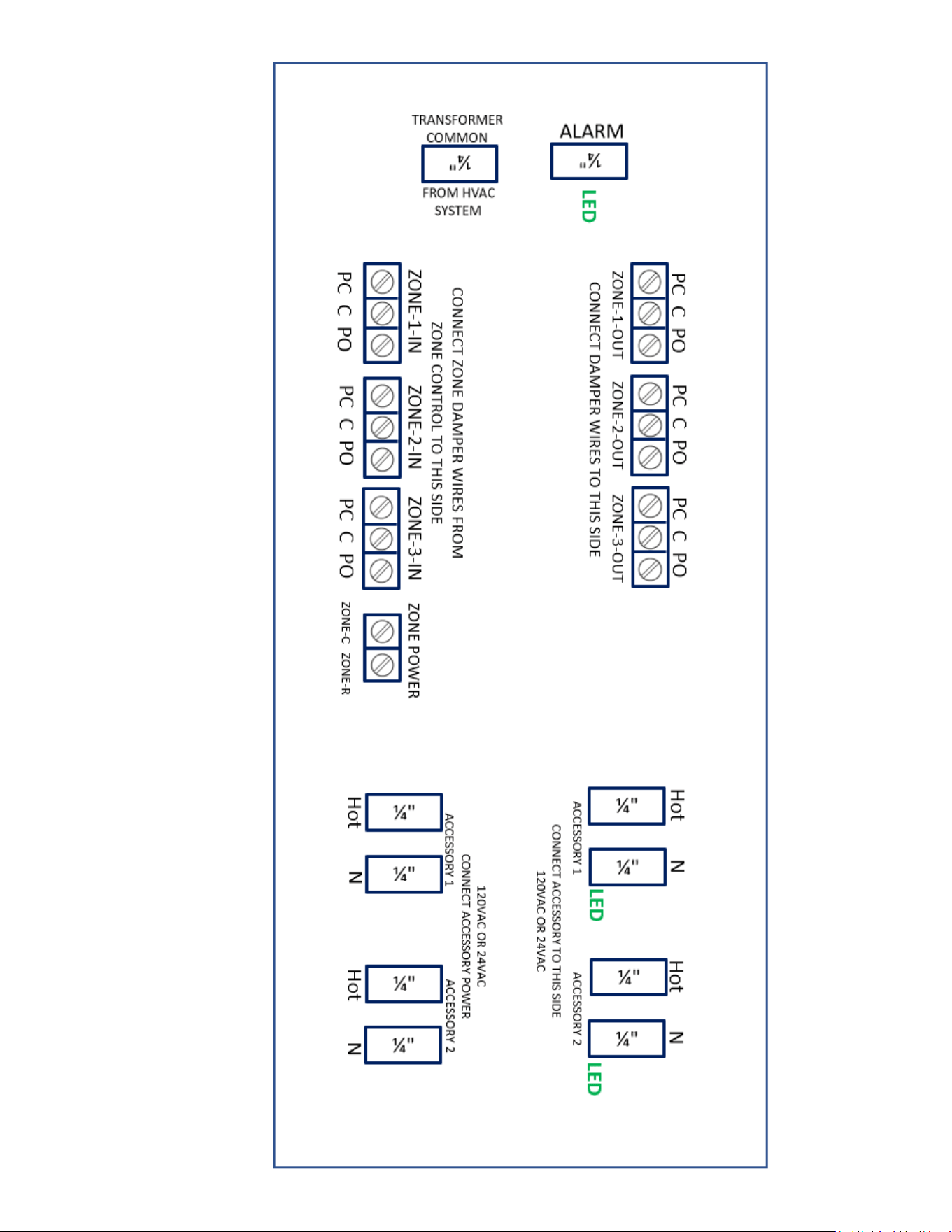
DS2, indicates when
the Alarm is active
DS1, indicates Zone
board has power applied
DS4, indicates
Accessory #1 is
powered
DS3, indicates
Accessory #2 is
powered
Leaderway Coahuila S.DE R.L.DE C.V:
5029515
Conforms to UL STD 60730-1
Certied to CAN/CSA STD E60730-1
Hangzhou Leaderway Electronics Co.,LTD
5029516
Conforms to UL STD 60730-1
Certied to CAN/CSA STD E60730-1
3
ZONING AND ACCESSORY CONTROL
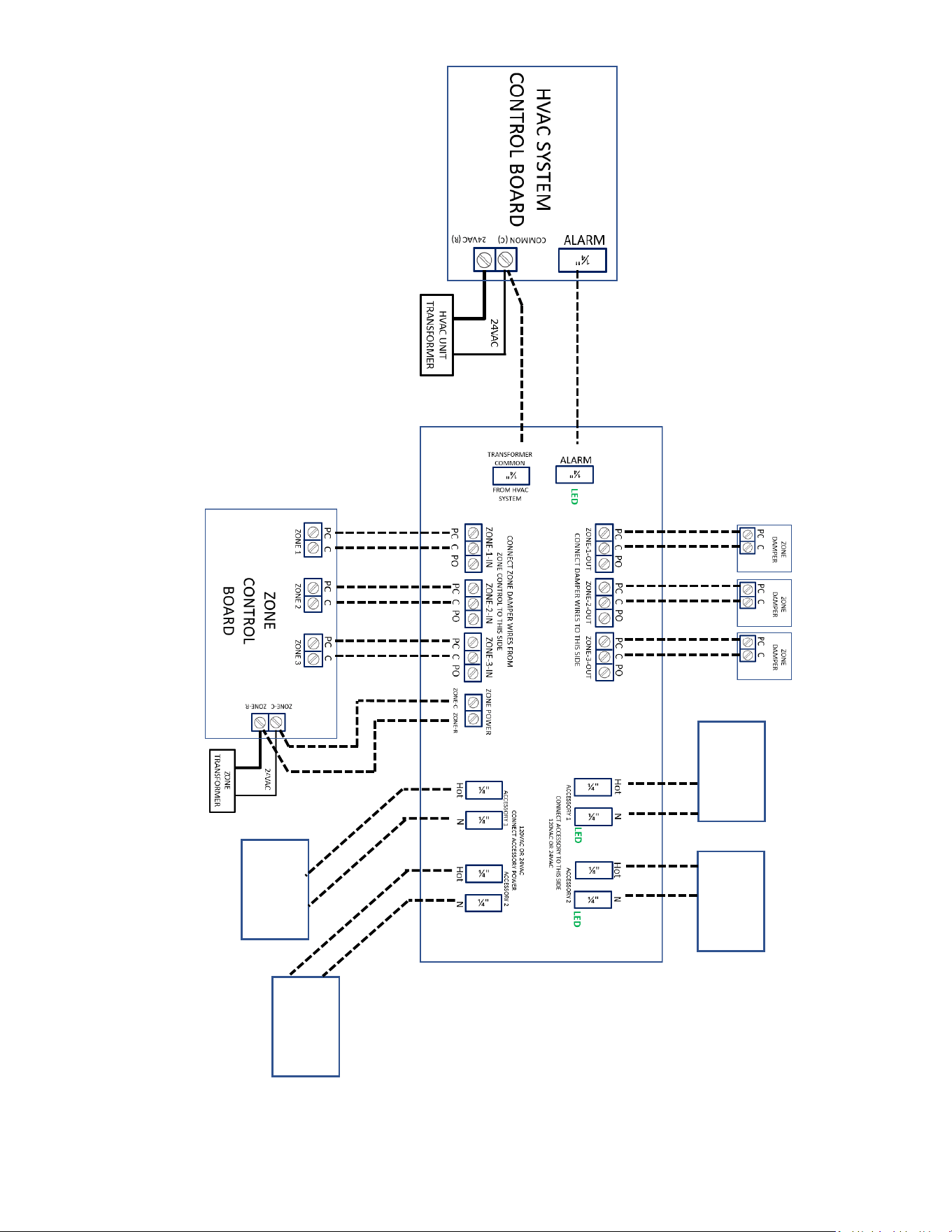
WIRING DIAGRAMS FOR VARIOUS ZONE DAMPERS
ACCESSORY 1
POWER
SOURCE
ACCESSORY 2
POWER
SOURCE
A2L ACCESSORY / ZONING CONTROL
ACCESSORY 2
ACCESSORY 1
APPLICATIONS USING
POWER OPEN / POWER CLOSED
ZONE DAMPERS
LED
4
A2L ACCESSORY / ZONING CONTROL
LED
ENLARGED VIEW OF A2L ACCESSORY / ZONING CONTROL
5
ACCESSORY 1
POWER
SOURCE
ACCESSORY 2
POWER
SOURCE
A2L ACCESSORY / ZONING CONTROL
ACCESSORY 2
ACCESSORY 1
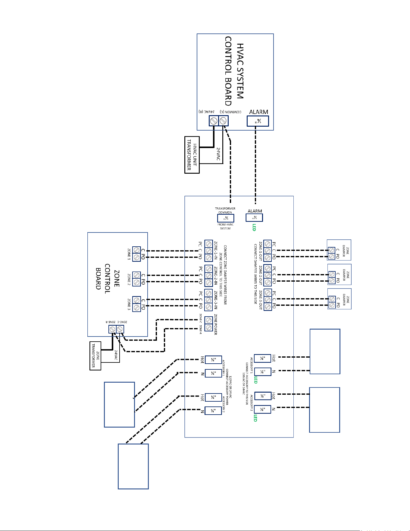
APPLICATIONS USING
POWER CLOSED / SPRING OPEN
ZONE DAMPERS
LED
6
ACCESSORY 1
POWER
SOURCE
ACCESSORY 2
POWER
SOURCE
A2L ACCESSORY / ZONING CONTROL
ACCESSORY 2
ACCESSORY 1
APPLICATIONS USING
POWER OPEN / SPRING CLOSED
ZONE DAMPERS
LED
7
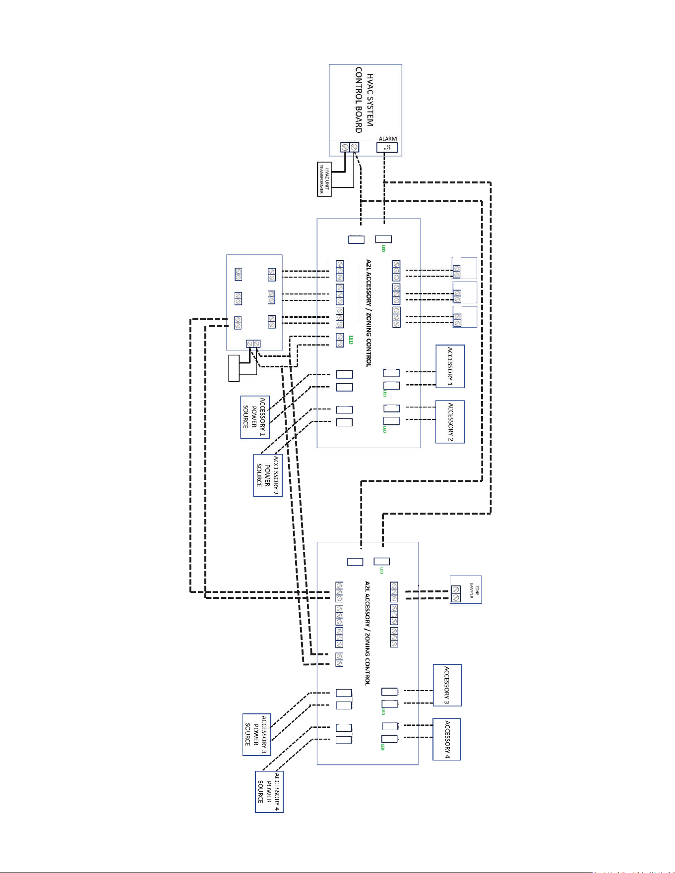
APPLICATIONS USING MORE THAN 3 ZONES OR 2 ACCESSORIES
(example shows 4 zones with power open / power closed dampers)
ZONE-1-OUT
ZONE-2-OUT ZONE-3-OUT
ZONE-1-IN
ZONE-2-IN
ZONE-3-IN
CONNECT DAMPER WIRES TO THIS SIDE
CONNECT ZONE DAMPER WIRES FROM
ZONE CONTROL TO THIS SIDE
ZONE POWER
ZONE-1-OUT ZONE-2-OUT
ZONE-3-OUT
ZONE-1-IN ZONE-2-IN
ZONE-3-IN
CONNECT DAMPER WIRES TO THIS SIDE
CONNECT ZONE DAMPER WIRES FROM
ZONE CONTROL TO THIS SIDE
ZONE POWER
CONNECT ACCESSORY TO THIS SIDE
120VAC OR 24VAC
120VAC OR 24VAC
CONNECT ACCESSORY POWER
ACCESSORY 1
ACCESSORY 2
ACCESSORY 1
ACCESSORY 2
CONNECT ACCESSORY TO THIS SIDE
120VAC OR 24VAC
120VAC OR 24VAC
CONNECT ACCESSORY POWER
ACCESSORY 1 ACCESSORY 2
ACCESSORY 1
ACCESSORY 2
PC C PO
PC C PO
PC C PO
ZONE-C ZONE-R
PC C PO
PC C PO
PC C PO
ZONE-C ZONE-R
PC C PO
PC C PO
PC C PO
PC C PO
PC C PO PC C PO
TRANSFORME
R COMMON
FROM HVAC
SYSTEM
ALARM
TRANSFORMER
COMMON
FROM HVAC
SYSTEM
ALARM
¼”
¼”
¼”
¼”
¼”
¼”
¼”
¼”
¼”
¼”
¼”
¼”
¼”
¼”
¼”
¼”
COMMON (c) 24VAC (R)
24VAC
ZONE
DAMPER
PC C PO
ZONE
DAMPER
PC C PO
ZONE
DAMPER
PC C PO
HOT N
HOT N
HOT N
HOT N
HOT N
HOT N
HOT N
HOT N
24VAC
ZONE
TRANSFORMER
ZONE
DAMPER
PC C PO
PC C PO
ZONE
DAMPER
ZONE
DAMPE
R
PC C PO
ZONE
DAMPE
R
PC C PO
PC C
PO
ZONE
DAMPE
R
ZONE-C ZONE-R
PC C PO PC C PO
PC C PO
PC C PO
PC C PO PC C PO
ZONE 6
ZONE 5
ZONE 4
ZONE 1
ZONE 2
ZONE 3
¼”
¼”
¼”
¼”
8
CONNECT DAMPER WIRES TO THIS SIDE
CONNECT ZONE DAMPER WIRES FROM
ZONE CONTROL TO THIS SIDE
ZONE POWER
CONNECT ACCESSORY TO THIS SIDE
120VAC OR 24VAC
120VAC OR 24VAC
CONNECT ACCESSORY POWER
ACCESSORY 1 ACCESSORY 2
ACCESSORY 1
ACCESSORY 2
PC C PO
PC C PO PC C PO
PC C PO
PC C PO PC C PO
ZONE-C ZONE-R
PC C PO
PC C PO
PC C PO
PC C PO
PC C PO PC C PO
TRANSFORME
R COMMON
FROM HVAC
SYSTEM
ALARM
TRANSFORMER
COMMON
FROM HVAC
SYSTEM
ALARM
¼”
¼”
¼”
¼”
¼”
¼”
¼”
¼”
¼”
¼”
¼”
¼”
¼”
¼”
¼”
¼”
24VAC
ZONE
DAMPER
C PO
ZONE
DAMPER
PC C PO
ZONE
DAMPER
PC C PO
HOT N
HOT N
HOT N
HOT N
HOT N
HOT N
HOT N HOT N
24VAC
ZONE
TRANSFORMER
ZONE
DAMPER
ZONE
DAMPER
ZONE
DAMPE
R
PC C PO
ZONE
DAMPE
R
PC C PO
R
R
R
R
R
R
R
R
R
R
R
R
R
R
R
R
R
R
R
R
R
R
R
R
R
R
R
R
R
R
R
R
R
R
R
R
R
R
R
R
R
R
R
R
R
R
R
R
R
R
R
R
R
R
R
R
R
R
R
R
R
R
R
R
R
R
R
R
R
R
R
R
R
R
R
R
R
R
R
R
R
R
R
R
R
R
R
R
R
R
R
R
R
R
R
R
R
R
R
R
R
R
R
R
R
R
R
R
R
R
R
R
R
R
R
PC C
PO
ZONE
DAMPE
R
ZONE-C ZONE-R
PC C PO
ZONE 6
ZONE 5
ZONE 4
ZONE 1
ZONE 2
ZONE 3
C PO
C PO
PC C PO
PC C PO
PC C PO
PC C PO
C PO
C PO
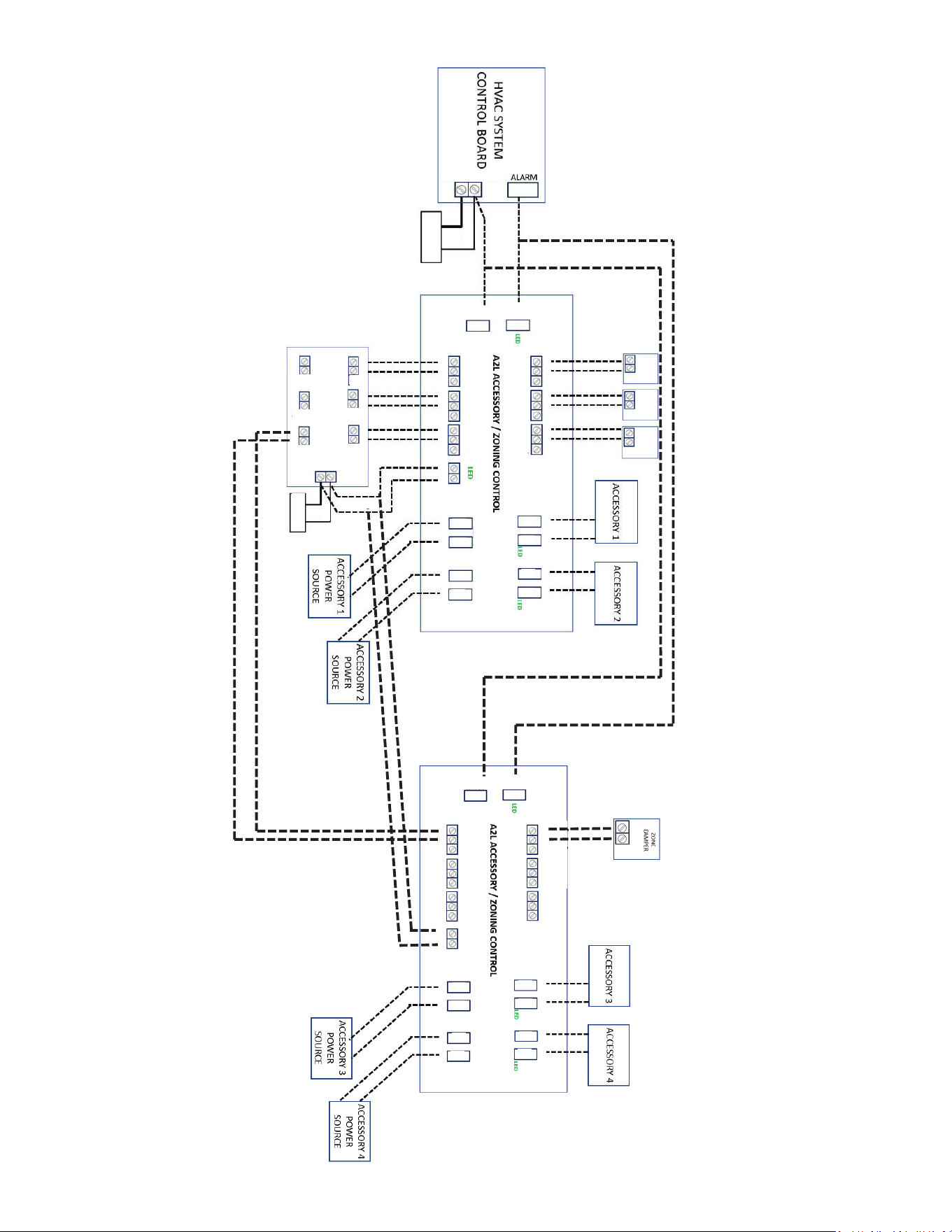
APPLICATIONS USING MORE THAN 3 ZONES OR 2 ACCESSORIES
(example shows 4 zones with power open / spring closed dampers)
¼”
¼”
¼”
¼”
(c) (R)
COMMON 24VAC
ZONE-1
OUT
ZONE-2
OUT
ZONE-3
OUT
CONNECT DAMPER WIRES TO THIS SIDE
ZONE-1
OUT
ZONE-2
OUT
ZONE-3
OUT
ZONE-1-IN
ZONE-2-IN
ZONE-3-IN
CONNECT ZONE DAMPER WIRES FROM
ZONE CONTROL TO THIS SIDE
ZONE POWER
ZONE-C ZONE-R
CONNECT ACCESSORY TO THIS SIDE
120VAC OR 24VAC
120VAC OR 24VAC
CONNECT ACCESSORY POWER
ACCESSORY 1 ACCESSORY 2
ACCESSORY 1
ACCESSORY 2
ACCESSORY 1 ACCESSORY 2
ZONE-1-IN
ZONE-2-IN
ZONE-3-IN
9
ZONE-1-OUT
ZONE-2-OUT
ZONE-3-OUT
CONNECT DAMPER WIRES TO THIS SIDE
CONNECT ZONE DAMPER WIRES FROM
ZONE CONTROL TO THIS SIDE
ZONE POWER
ZONE-1-OUT
ZONE-2-OUT
ZONE-3-OUT
ZONE-1-IN
ZONE-2-IN
ZONE-3-IN
CONNECT DAMPER WIRES TO THIS SIDE
CONNECT ZONE DAMPER WIRES FROM
ZONE CONTROL TO THIS SIDE
ZONE POWER
CONNECT ACCESSORY TO THIS SIDE
120VAC OR 24VAC
120VAC OR 24VAC
CONNECT ACCESSORY POWER
ACCESSORY 1
ACCESSORY 2
ACCESSORY 1
ACCESSORY 2
CONNECT ACCESSORY TO THIS SIDE
120VAC OR 24VAC
120VAC OR 24VAC
CONNECT ACCESSORY POWER
ACCESSORY 1
ACCESSORY 2
ACCESSORY 1
ACCESSORY 2
PC C PO
PC C PO
PC C PO
ZONE-C ZONE-R
PC C PO
PC C PO PC C PO
ZONE-C ZONE-R
PC C PO
PC C PO
PC C PO
PC C PO
PC C PO PC C PO
TRANSFORMER
COMMON
FROM HVAC
SYSTEM
ALARM
TRANSFORMER
COMMON
FROM HVAC
SYSTEM
ALARM
¼”
¼”
¼”
¼”
¼”
¼”
¼”
¼”
¼”
¼”
¼”
¼”
¼”
¼”
¼”
¼”
COMMON (c) 24VAC (R)
24VAC
ZONE
DAMPER
PC C
PC C
HOT N
HOT
N
HOT N
HOT N
HOT N
HOT N
HOT N HOT N
24VAC
ZONE
TRANSFORMER
ZONE
DAMPER
ZONE
DAMPER
ZONE
DAMPE
R
PC C PO
ZONE
DAMPE
R
PC C PO
R
R
R
R
R
R
R
R
R
R
R
R
R
R
R
R
R
R
R
R
R
R
R
R
R
R
R
R
R
R
R
R
R
R
R
R
R
R
R
R
R
R
R
R
R
R
R
R
R
R
R
R
R
R
R
R
R
R
R
R
R
R
R
R
R
R
R
R
R
R
R
R
R
R
R
R
R
R
R
R
R
R
R
R
R
R
R
R
R
R
R
R
R
R
R
R
R
R
R
R
R
R
R
R
R
R
R
R
R
R
R
R
R
R
R
PC C
PO
ZONE
DAMPE
R
ZONE-C ZONE-R
PC C PO
ZONE 6
ZONE 5
ZONE 4
ZONE 1
ZONE 2
ZONE 3
PC C PO
PC C PO
PC C PO
PC C PO
PC C
PC C
PC C
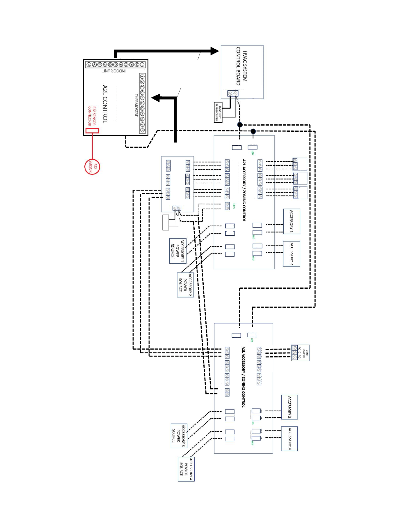
APPLICATIONS USING MORE THAN 3 ZONES OR 2 ACCESSORIES
(example shows 4 zones with Power Closed / Spring Open dampers)
ZONE-1-IN
ZONE-2-IN
ZONE-3-IN
¼”
¼”
HVAC UNIT
TRANSFORMER
¼”
¼”
¼”
10
ZONE-1-OUT ZONE-2-OUT
ZONE-3-OUT
CONNECT DAMPER WIRES TO THIS SIDE
CONNECT ZONE DAMPER WIRES FROM
ZONE CONTROL TO THIS SIDE
ZONE-1-OUT ZONE-2-OUT
ZONE-3-OUT
ZONE-1-IN
ZONE-2-IN
ZONE-3-IN
CONNECT DAMPER WIRES TO THIS SIDE
CONNECT ZONE DAMPER WIRES FROM
ZONE CONTROL TO THIS SIDE
ZONE POWER
CONNECT ACCESSORY TO THIS SIDE
120VAC OR 24VAC
120VAC OR 24VAC
CONNECT ACCESSORY POWER
ACCESSORY 1
ACCESSORY 2
ACCESSORY 1
ACCESSORY 2
CONNECT ACCESSORY TO THIS SIDE
120VAC OR 24VAC
120VAC OR 24VAC
CONNECT ACCESSORY POWER
ACCESSORY 1
ACCESSORY 2
ACCESSORY 1
ACCESSORY 2
PC C PO
PC C PO PC C PO
ZONE-C ZONE-R
PC C PO
PC C PO PC C PO
ZONE-C ZONE-R
PC C PO
PC C PO
PC C PO
PC C PO
PC C PO PC C PO
TRANSFORMER
COMMON
FROM HVAC
SYSTEM
ALARM
TRANSFORMER
COMMON
FROM HVAC
SYSTEM
ALARM
¼”
¼”
¼”
¼”
¼”
¼”
¼”
¼”
¼”
¼”
¼”
¼”
¼”
¼”
¼”
¼”
24VAC
ZONE
DAMPER
PC C PO
ZONE
DAMPER
PC C PO
ZONE
DAMPER
PC C PO
HOT N
HOT N
HOT N
HOT N
HOT N
HOT N
HOT N HOT N
24VAC
ZONE
TRANSFORMER
ZONE
DAMPER
PC C PO
PC C PO
ZONE
DAMPER
ZONE
DAMPE
R
PC C PO
ZONE
DAMPE
R
PC C PO
PC C
PO
ZONE
DAMPE
R
ZONE-C ZONE-R
PC C PO PC C PO
PC C PO
PC C PO
PC C PO PC C PO
ZONE 6
ZONE 5
ZONE 4
ZONE 1
ZONE 2
ZONE 3
¼”
¼”
¼”
¼”
ZONE CONTROL SIGNALS
OUT TO HVAC SYSTEM
STANDARD
THERMOSTAT
CONNECTIONS
¼” Alarm
Terminal
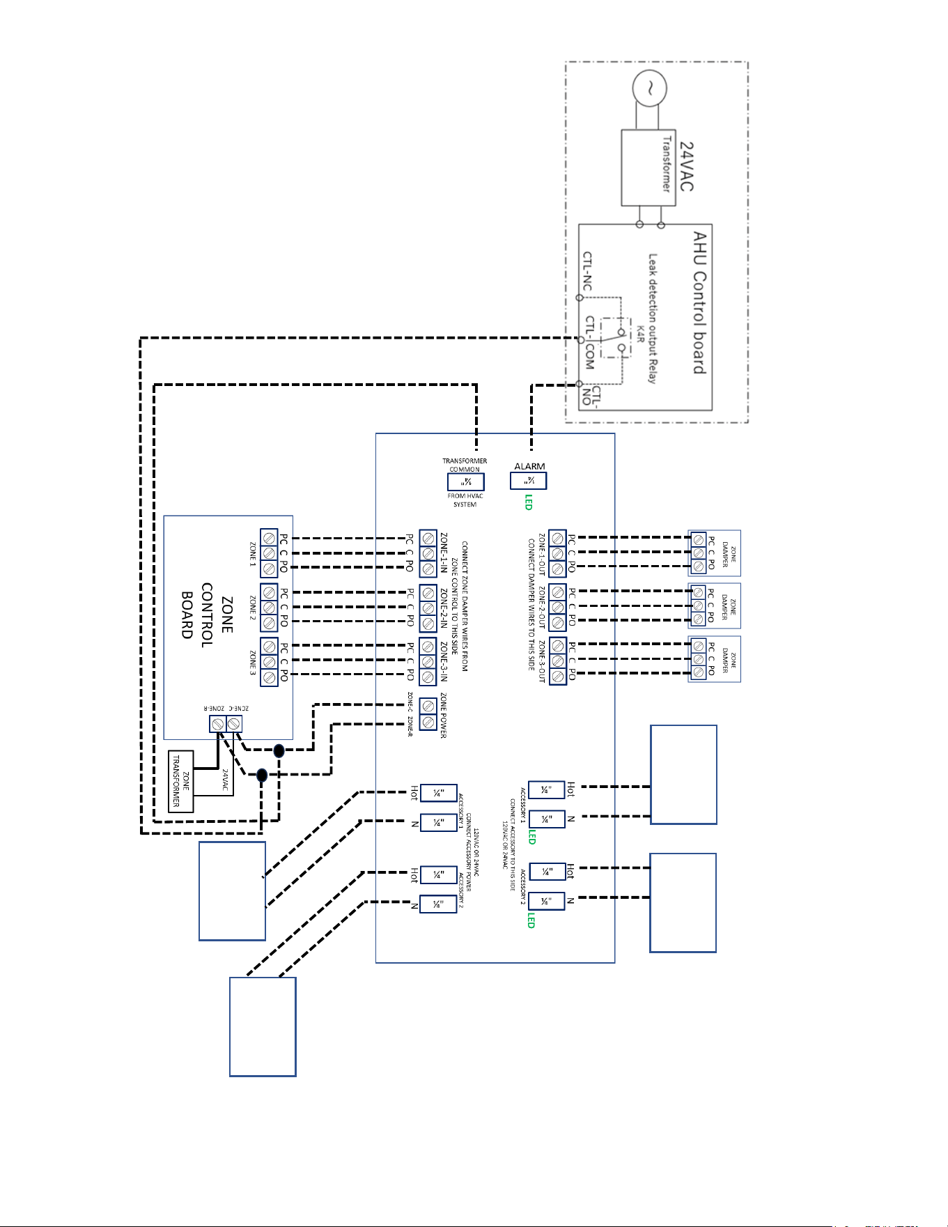
Example of Non-A2L Furnace Integration Kit
+ A2L Accessory /Zoning Control
COMMON (c) 24VAC (R)
ZONE-1-IN
ZONE-2-IN
ZONE POWER
ZONE-3-IN
PCB
11
ACCESSORY 1
POWER
SOURCE
ACCESSORY 2
POWER
SOURCE
A2L ACCESSORY / ZONING CONTROL
ACCESSORY 2
ACCESSORY 1
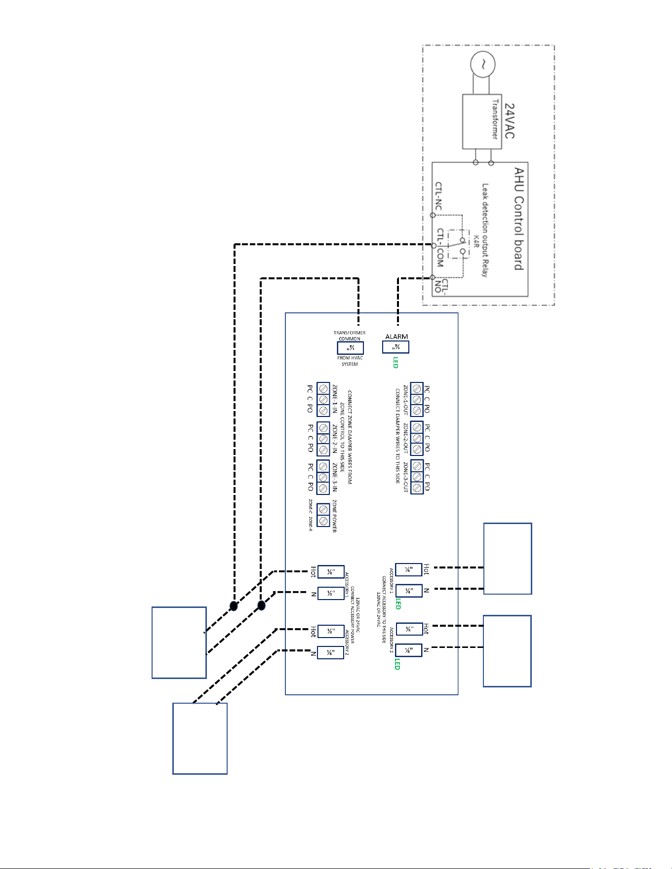
ZONE Application with
CTL-COM and CTL-NO
Terminals
LED
Example of DFVE, AHVE or MBVK model + Zoning control
12
ACCESSORY 1
POWER
SOURCE
(24VAC)
A2L ACCESSORY / ZONING CONTROL
ACCESSORY 2
ACCESSORY 1
LED
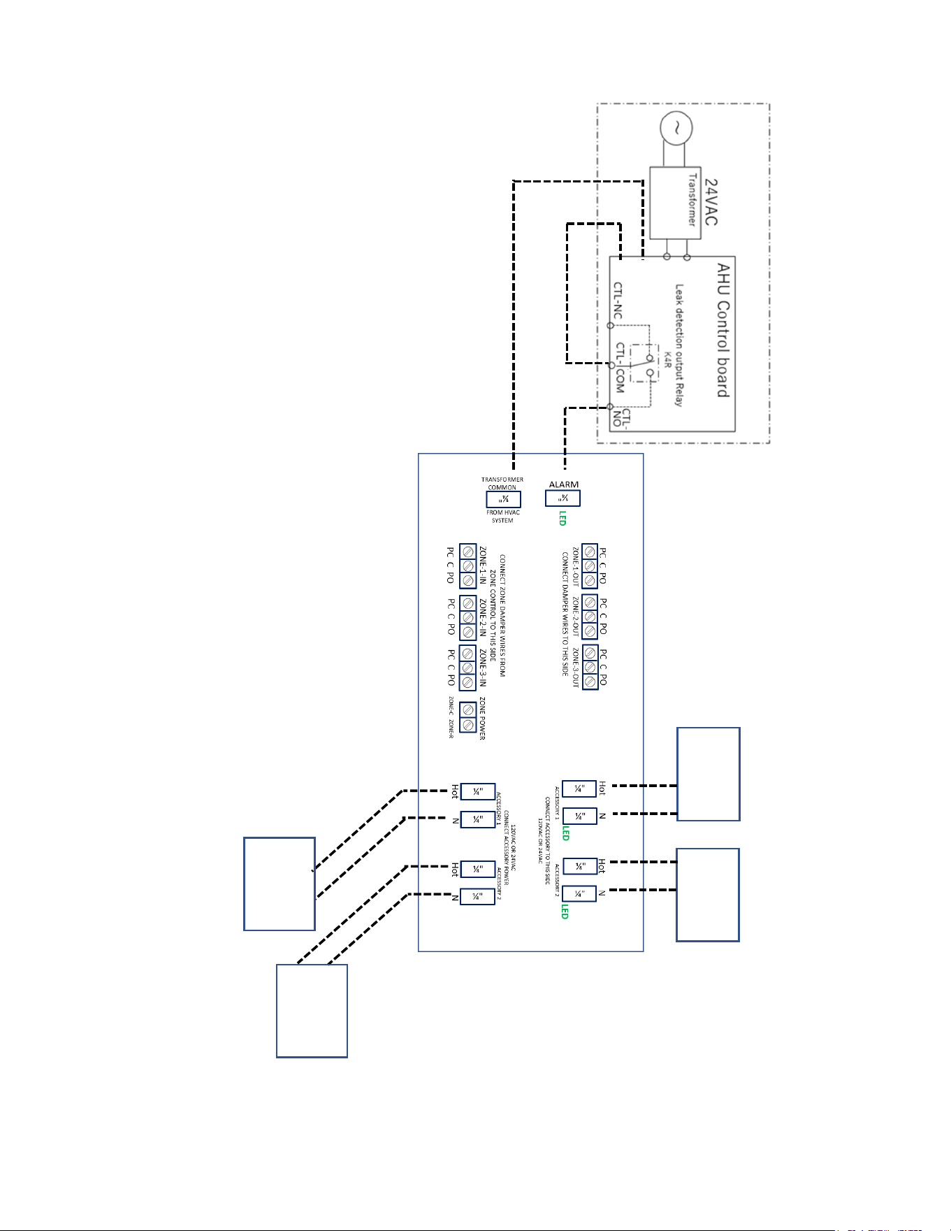
USE THIS WIRING METHOD IF ACCESSORY POWER SOURCE IS 24VAC
DO NOT USE THIS WIRING METHOD IF
ACCESSORY POWER SOURCE IS 120VAC
24VAC Accessory
Application with CTL-COM
and CTL-NO Terminals
ACCESSORY 2
POWER
SOURCE
(24VAC)
Example of DFVE, AHVE or MBVK model + 24VAC Accessory Application
13
A2L ACCESSORY / ZONING CONTROL
ACCESSORY 2
ACCESSORY 1
APPLICATIONS USING
POWER OPEN / POWER
CLOSED ZONE DAMPERS
LED
C
R
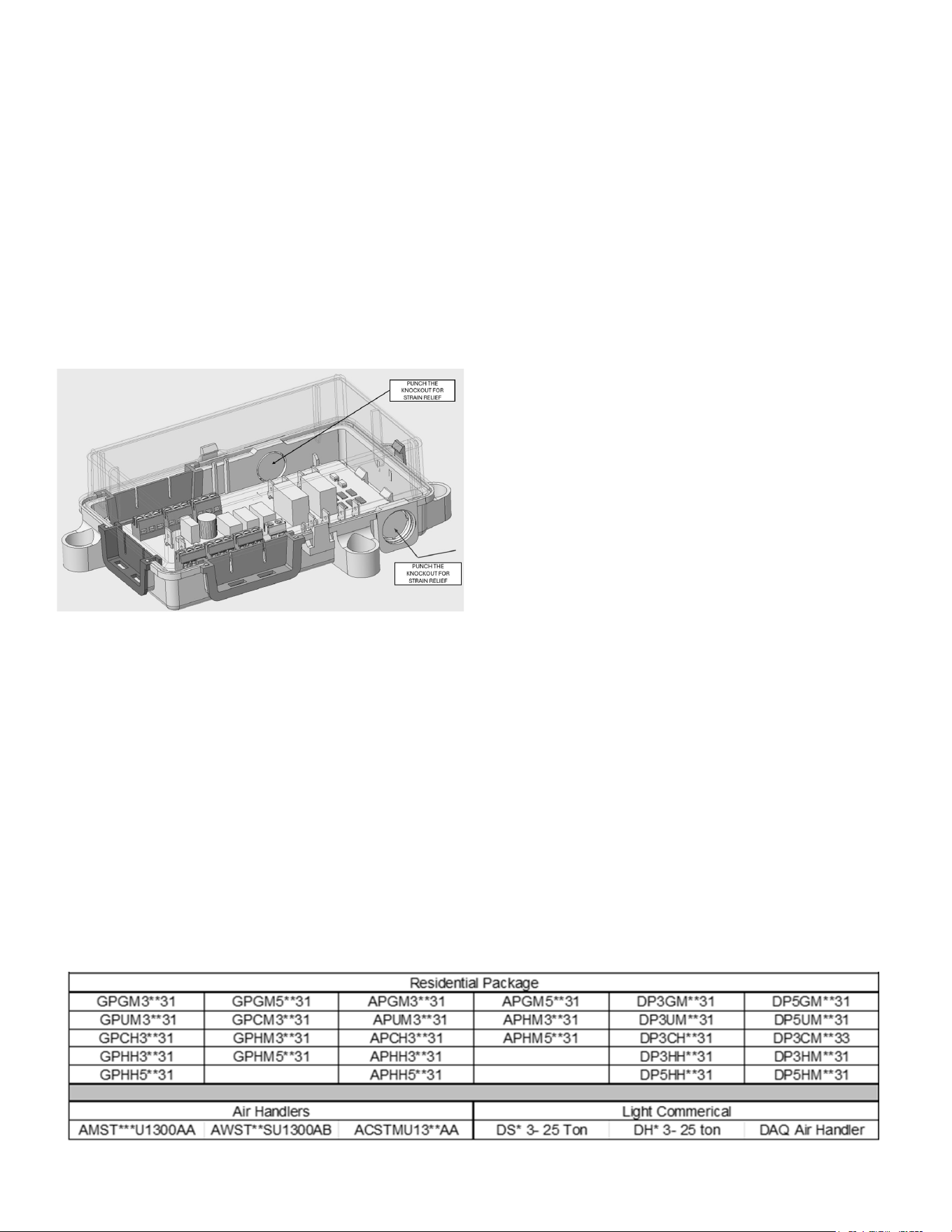
USE THIS WIRING
METHOD IF ACCESSORY
POWER IS 120VAC
120VAC Accessory
Application with CTL-COM
and CTL-NO Terminals
ACCESSORY 1
POWER
SOURCE
(120VAC)
ACCESSORY 1
POWER
SOURCE
(120VAC)
Example of DFVE, AHVE or MBVK model + 120VAC Accessory Application
NOTE: Do not connect C and R of the communication terminal to locations other than those specified.
14
STRAIN RELIEF FOR HIGH VOLTAGE CONNECTIONS
When connecting 120 volt hot and neutral wires to the
Accessory/Zoning control, National Electrical Code (NEC)
requires the wiring be secured with a strain relief. Install
a 1/2” box connector for Romex or conduit into each side
of the Accessory / Zoning Kit PCB Case using the 1/2”
threaded connections. Route the 120 volt wiring into the
Romex or conduit connector and connect the wires as
shown in this IO.
With the 1/2” threaded connections on the PCB Case,1/2”
box connectors shall be used. The box connectors would
thread into the enclosure (one on entering side and one
on exiting side). The strain relief would tighten down the
Romex or conduit.
A2L Accessory / zoning control installation steps
Zoning Applications
The A2L Accessory / Zoning Control can support up to 3
zones. If the system uses more than 3 zones, additional
A2L Accessory / Zoning Controls will be needed to support
up to the remaining zones.
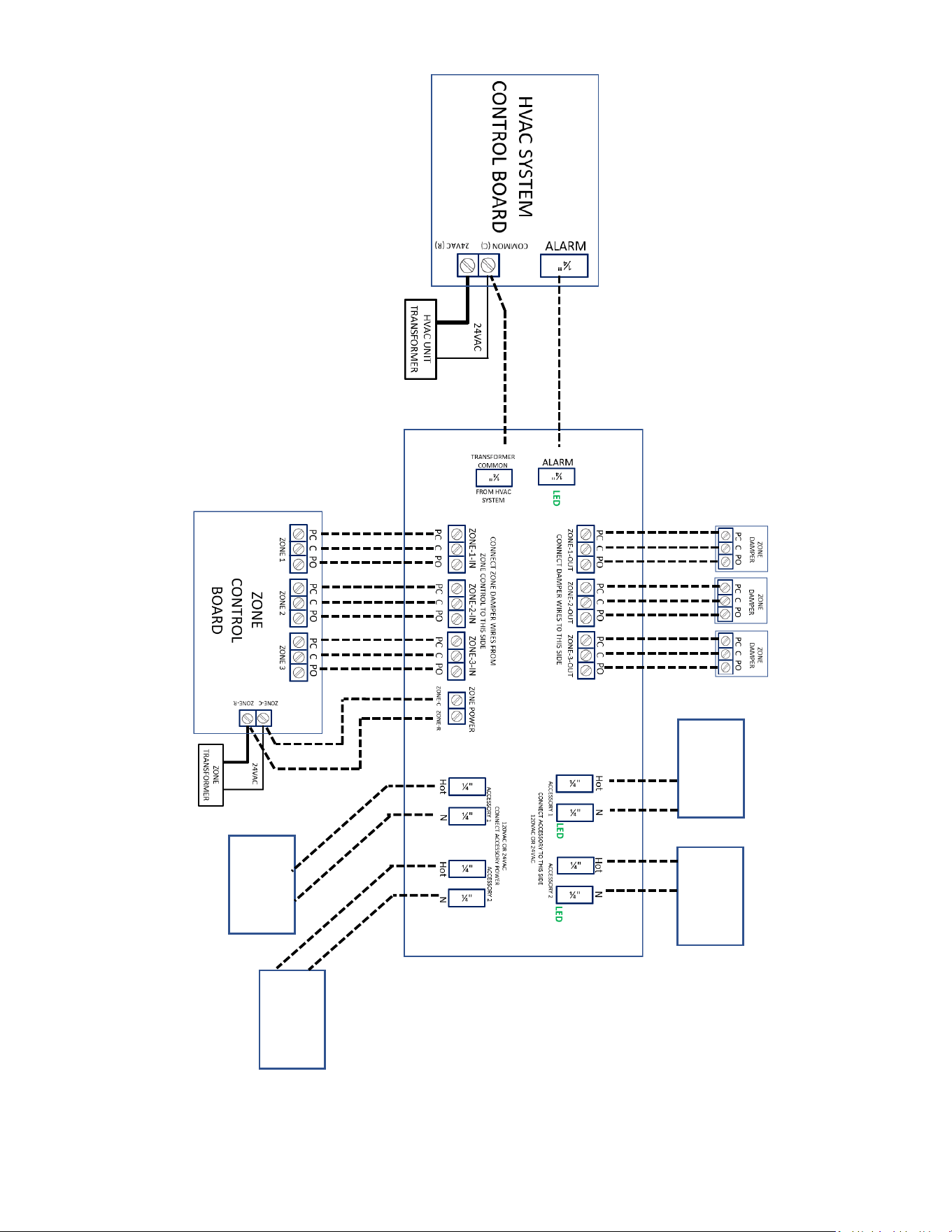
WIRING FOR ZONING APPLICATION
1) Identify the style of zoning control being used for the
application. All standard zoning control systems use
either 1) power open / spring closed, 2) power closed /
spring open or 3) power open / power closed electronic
dampers. The A2L Accessory / Zoning Control is
compatible with all types of zone dampers.
2) Locate the appropriate wiring diagram for the type of
dampers being used.
3) Identify the damper connection points on the zone
control (if the zoning control was previously installed,
the zone dampers will already be wired into these
connection points)
4) If the zoning control was previously installed, remove
the damper wires from the zone control and move
them to the side of the A2L Accessory / Zoning Control
labeled “CONNECT DAMPER WIRES TO THIS SIDE”.
If this is a new installation of the zone system, this step
is not needed.
a. NOTE: make sure to move wires from zone 1 on the
zone control to zone 1 on the A2L Accessory / Zoning
Control (same for zone 2 and 3).
5) Per the wiring diagram identied for the type of damper
being used, make the appropriate wire connections
between the zone control and the A2L Accessory /
Zoning Control terminals labeled “CONNECT ZONE
DAMPER WIRES FROM ZONE CONTROL TO THIS
SIDE”
a. Make sure the zones match between the zone
control and the A2L Accessory / Zoning Control
6) If this is a new installation of the zone system, connect
zone dampers to the A2L Accessory / Zoning Control
terminals labeled “CONNECT DAMPER WIRES TO
THIS SIDE”.
a. Make sure wiring is made to the correct zone on the
A2L Accessory / Zoning Control
7) Locate the refrigerant detection system for the HVAC
unit. This will be a control board mounted inside air
handler, furnace, modular blower or possibly a kit
mounted outside the indoor unit. The control will
have a ¼” terminal on it marked ALARM or CTL-NO.
Once identied, run a wire from the ALARM or CTL-
NO terminal on the refrigerant detection system to the
ALARM terminal on the A2L Accessory / Zoning Control
(this is shown in the wiring diagram). A red wire is
provided with the kit for this connection.
8) If the 1/4” terminal from step 7 was marked ALARM,
run an additional wire from the A2L Accessory /
Zoning Control ¼” terminal marked “TRANSFORMER
COMMON FROM HVAC UNIT” to any common point
inside the HVAC unit. A Blue wire is provided with the
kit for this connection.
NOTE: This step is connecting to the HVAC system
transformer, NOT the zoning control transformer.
They are separate transformers and need to be kept
separate.
15
If the 1/4” terminal from step 7 was marked CTL-NO,
see the wiring diagram labeled “ZONE Application
with CTL-COM and CTL-NO Terminals”. If multiple
accessories are not being used, the kit contains
additional wire that can be used to make the following
connections.
a. One wire needs to be run from the Zone system
transformer R terminal to the CTL-COM 1/4” terminal
inside HVAC system.
b. One additional wire needs to be run from the A2L
Accessory / Zoning Control 1/4” terminal marked
“TRANSFORMER COMMON FROM HVAC UNIT” to
the common terminal of the Zone system transformer
(NOT TO THE HVAC UNIT’S TRANSFORMER
COMMON IN THIS CASE).
9) Locate the main 24VAC transformer power input to
the Zone control. The wires in this terminal should be
coming from the separate zone transformer.
10) Per the wiring diagram, run two wires from the zone
control 24VAC power input terminal to the A2L
Accessory / Zoning Control terminals marked “ZONE
POWER, ZONE-C, ZONE-R”.
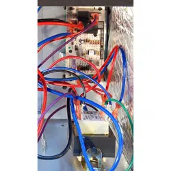
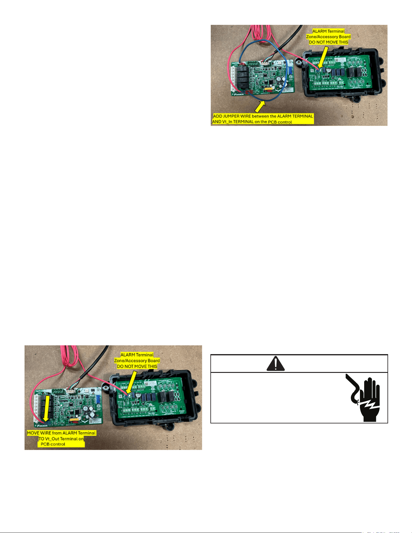
Models containing the PCBCM301V0001 (Refrigerant
Detection System control board) require two additional
wiring steps. See the table below for a list of models
that may contain the PCBCM301V0001 (Refrigerant
Detection System control board). If the PCBCM301V0001
(Refrigerant Detection System control board) is in your
system, please follow these two steps.
1. Remove the wire from the Alarm terminal on
the PCBCM301V0001 (Refrigerant Detection
System control board) and move it to the (VT Out)
terminal. See image below. You will now have
a wire connecting the (Vt Out) terminal on the
PCBCM301V0001 (Refrigerant Detection System
control board) and the Alarm Terminal on the Zone/
Accessory Board.
2. Add a jumper wire between the Alarm Terminal and the
(Vt In) Terminal on the PCBCM301V0001 (Refrigerant
Detection System control board). See image below.
Zone Application Test
RUNNING THE SYSTEM TEST IS MANDATORY FOR
ALL INSTALLATIONS. THE HVAC SYSTEM MUST
NOT COMPLETE COMMISSIONING UNTIL THE
INSTALLATION STEPS LISTED IN THIS MANUAL HAVE
BEEN SUCCESSFULLY COMPLETED.
1) Apply power to the HVAC system. A green LED by the
Zone Power terminals will turn ON indicating zone
transformer power has been applied.
2) Conrm all zone dampers are closed
a. Note that some zone controls default on all dampers
to the OPEN position when the system is idle and
there is no call for cooling, heating, or fan. For these
systems, select any single zone and, for that zone
only, give the unit a fan call (if a fan only call is not
available, provide a cooling or heating call to that one
zone). Leave the other zones o.
b. Doing this will ensure the one zone calling remains
open while the zone control closes dampers to the
remaining zones.
3) Disconnect the unit from the power line and locate the
R-32 sensor cable and the refrigerant leak detection
system control board that it is connected to.
WARNING
HIGH VOLTAGE
DISCONNECT ALL POWER BEFORE SERVICING
OR INSTALLING THIS UNIT. MULTIPLE POWER
SOURCES MAY BE PRESENT. FAILURE TO DO SO
MAY CAUSE PROPERTY DAMAGE, PERSONAL
INJURY OR DEATH.
This control board will be mounted inside an air
handler, furnace, modular blower or possibly a kit
mounted outside the indoor unit. Once located,
disconnect the R-32 Sensor from the refrigerant leak
detection system control board. After disconnecting
the R-32 Sensor, assemble the HVAC unit back as per
the nal installation setup, followed by reconnecting
the power to the HVAC unit. Doing this will energize
the Alarm or CTL-NO terminal of the refrigerant leak
16
detection system within 30 seconds.
4) Conrm the red LED next to the ¼” ALARM terminal on
the A2L Accessory / Zoning Control board is ON. This
conrms the HVAC system has been properly wired to
the control board.
a. NOTE: the green LED will remain on. This LED
indicates zone transformer power has been applied
to the control.
5) Conrm all zones fully open the dampers and remain
open. Disconnect the unit from the power line and
reconnect the R-32 sensor to its original location from
step 3. After reassembling the HVAC unit, reconnect
the power line. The Red LED on the A2L Accessory /
Zoning Control board will have turned OFF and all the
zone dampers will return to the original state they were
in after step 1.
6) This completes the zoning test of the A2L Accessory /
Zoning Control board.
Accessory Application
Wiring For Accessory Application
NOTE: The A2L Accessory / Zoning Control is designed
to remove main power from an installed accessory to
ensure the device is o in the event of a refrigerant leak.
Accessory control wires (from a thermostat, humidistat, air
circulation timer, etc.) are to be wired separately. White
and Black wires are provided with the kit to make the
appropriate connections.
NOTE: A2L Accessory / Zoning Control will support 2
accessories. If more than two are used, an additional A2L
Accessory / Zoning Control will be needed.
1) Connect the two power wires from the accessory device
to the A2L Accessory / Zoning Control 1/4” terminals
labeled “CONNECT ACCESSORY TO THIS SIDE”.
White and Black wires are provided with the kit to make
the appropriate connections.
a. Two terminals are marked ACCESSORY 1 and two
other terminals are marked ACCESSORY 2. note
which side each accessory is connected.
2) Connect power wire, from the Accessory’s main power
source to the A2L Accessory / Zoning Control ¼”
terminals labeled “CONNECT ACCESSORY POWER”.
White and Black wires are provided with the kit to make
the appropriate connections.
a. Two terminals are marked ACCESSORY 1 and two
other terminals are marked ACCESSORY 2.
b. Make sure to connect power to the correct terminals
associated with the installed accessory.
c. 120VAC or 24VAC power can be applied
3) Locate the refrigerant detection system for the HVAC
unit. This will be a control board mounted inside or
possibly a kit mounted outside the unit. The control will
have a ¼” terminal on it marked ALARM or CTL-NO.
Once Identied, run a wire from the ALARM or CTL-NO
terminal on the refrigerant leak detection system to the
ALARM terminal on the A2L Accessory / Zoning Control
(this is shown in the wiring diagram). A red wire is
provided with the kit for this connection.
4) If the 1/4” terminal from step 7 was marked ALARM,
run an additional wire from the A2L Accessory /
Zoning Control ¼” terminal marked “TRANSFORMER
COMMON FROM HVAC SYSTEM” to any common
point inside the HVAC unit. A blue wire is provided with
the kit for this connection. If the 1/4” terminal from step
7 was marked CTL-NO, see the wiring diagrams labeled
“Accessory Application with CTL-COM and CTL-NO
Terminals”. Dierent wiring methods are shown if the
accessory power source is 24VAC or if it is 120VAC.
Make sure to use the correct wiring for the power source
being used.
ACCESSORY APPLICATION TEST
RUNNING THE SYSTEM TEST IS MANDATORY FOR
ALL INSTALLATIONS. THE HVAC SYSTEM MUST
NOT COMPLETE COMMISSIONING UNTIL THE
INSTALLATION STEPS LISTED IN THIS MANUAL HAVE
BEEN SUCCESSFULLY COMPLETED.
1) Turn power on to HVAC system and accessory devices.
Conrm accessory devices are appropriately powered.
2) Green LEDs next to Accessory 1 and Accessory 2
terminals will be ON if power is being applied to
those terminals. The LED will only be energized if an
Accessory is installed and powered.
3) Disconnect the unit from the power line and locate the
R-32 sensor cable and the refrigerant leak detection
system control board that it is connected to.
WARNING
HIGH VOLTAGE
DISCONNECT ALL POWER BEFORE SERVICING
OR INSTALLING THIS UNIT. MULTIPLE POWER
SOURCES MAY BE PRESENT. FAILURE TO DO SO
MAY CAUSE PROPERTY DAMAGE, PERSONAL
INJURY OR DEATH.
This control board will be mounted inside an air handler,
furnace, modular blower or possibly a kit mounted
outside the indoor unit. Once located, disconnect
the R-32 Sensor from the refrigerant leak detection
system control board. After disconnecting the R-32
Sensor, assemble the HVAC unit back as per the nal
installation setup, followed by reconnecting the power
to the HVAC unit. Doing this will energize the Alarm
or CTL-NO terminal of the refrigerant leak detection
system within 30 seconds.
4) Conrm the red LED next to the ¼” ALARM terminal
on the A2L Accessory / Zoning Control is ON. This
conrms the HVAC system has been properly wired to
the control.
5) Conrm the green LEDs next to Accessory 1 and
Accessory 2 terminals are both OFF (no power is being
applied to the accessories).
6) Conrm the installed accessories are o.

17
7) Disconnect the unit from the power line and reconnect
the R-32 sensor to its original location from step 3.
After reassembling the HVAC unit, reconnect the
power line. The Red LED on the A2L Accessory /
Zoning Control board will have turned OFF and all the
accessories will return to the original state they were in
after step 1.
8) Conrm the Accessories have turned back on.
9) This completes the accessory test of the R-32
A2L Accessory / Zoning Control
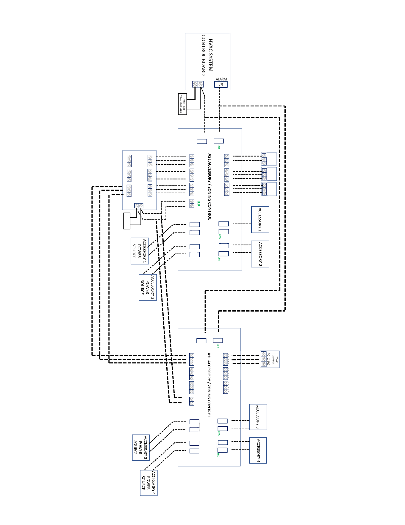
Applications with more than 3 zones or more than 2
accessories will require a second A2L Accessory / Zoning
Control. Using the wiring diagram provided, jump the Alarm
and HVAC Common terminals to the second control and
wire zone dampers / accessories as shown. Note: power
from the zoning transformer must also be applied to the
second A2L Accessory / Zoning Control (shown in wiring
diagram). All test steps as detailed in this manual for zone
and accessory installs will also apply to systems using
more than one A2L Accessory / Zoning Control.

18
PAGE LEFT INTENTIONALLY BLANK

19
PAGE LEFT INTENTIONALLY BLANK
20
CUSTOMER FEEDBACK
We are very interested in all product comments.
Please ll out the feedback form on one of the following links:
Daikin Products: (https://daikincomfort.com/contact-us)
Goodman
®
Brand Products: (http://www.goodmanmfg.com/about/contact-us).
Amana
®
Brand Products: (http://www.amana-hac.com/about-us/contact-us).
You can also scan the QR code on the right for the product brand you
purchased to be directed to the feedback page.
DAIKIN
AMANA
®
BRAND
GOODMAN
®
BRAND
19001 Kermier Rd., Waller, TX 77484
wwww.daikincomfort.com • www.goodmanmfg.com • www.amana-hac.com
© 2025 Daikin Comfort Technologies Manufacturing, Inc.
is a registered trademark of Maytag Corporation or its related companies
and is used under license. All rights reserved.