
Installation Instructions
& Owner's Manual
Commercial
Water Filters
UF Series Membrane Filtration System
aosmith.com/commercialwatertreatment

Pre-installation Instructions for Dealers ....................................................3
Bypass Valve ...........................................................................4
Installation .............................................................................5
Programming Procedures .............................................................. 11
Start-up Instructions ................................................................... 13
Operating Displays and Maintenance .................................................... 14
Troubleshooting Guide ................................................................. 16
Replacement Parts .................................................................... 21
Installation Fitting Assemblies .......................................................... 26
Specifications ......................................................................... 28
Additional Programming Settings ........................................................ 29
Warranty ............................................................................ 31
Quick Reference Guide ................................................................. 32
STARTUP DATA
Installation Date ______________________________
Installation Dealer _____________________________
Separate Source Reg. Kit Installed ________________
Volume Between Flushing (gallons) _______________
Time Between Regeneration (hrs)_________________
Your A. O. Smith UF Filtraon system is a precision built, high quality product. This unit will deliver quality
water for many years to come, when installed and operated properly. Please study this manual carefully
and understand the cauons and notes before installing and operaon. This manual should be kept for
future reference. If you have any quesons regarding your system, contact your local dealer.
YOUR WATER TEST
Hardness ______________________ gpg
Iron __________________________ ppm
pH ___________________________ number
*Nitrates ______________________ ppm
Manganese ____________________ ppm
Sulphur _______________________ yes/no
Total Dissolved Solids ____________
*Over 10 ppm may be harmful for human consumption.
Water conditioners do not remove nitrates or coliform bacteria,
this requires specialized equipment.
Table of ContentsTable of Contents

3
PRE-INSTALLATION INSTRUCTIONS
THE DEALER SHOULD...
•Read this page and guide the installer
regarding time of regeneration, service
alarm, and programming settings prior to
installation.
THE INSTALLER SHOULD...
•Program installer regarding time of
regeneration, service alarm, and
programming settings prior to installation.
•Read Operating Displays and Maintenance
section.
•Set the time of day
•Read Power Loss and Error Display section.
•Ensure that system and installation are in
compliance with all state and local laws and
regulations
•Allow space for membrane removal
THE HOMEOWNER SHOULD...
•Read Programming Procedures section.
•Read Operating Displays and Maintenance
section.
The manufacturer has preset the water treatment unit’s sequence of cycles and cycle times.
GENERAL OPERATING DISPLAYS & NAVIGATION
During normal operation, the default user displays are “time of day” and “gallons per minute”. Flow rate, vacation mode, capacity remaining, and
days to a regeneration are optional displays. For more explanation, consult the “operating displays and maintenance section”. Pressing the NEXT
button on a general operating screen will cycle through the available operating displays.
In any screen other than a general operating display, the NEXT button will proceed to the next step, the REGEN button will return to a previous step,
and the CLOCK button will return to the general operating displays. Any changes made prior to the exit will be incorporated. If no buttons are pressed
within five minutes, the display will return to the general operating displays.
ULTRA FILTRATION FLUSHING SCHEDULE
The UF Series Filter is factory preset to backwash every day at midnight. This is dependent on the quality of water being treated and may
be adjusted by the installing dealer based on the water quality. A post ultra-filtration pressure tank may be installed to ensure a sufficient
flow of water and pressure to the home during a flush cycle.
IMPORTANT: If a post pressure tank is used a check valve may be required to allow for treated water regeneration. In this case an
expansion tank should be installed to account for thermal expansion. See drawing in the back of this manual.
Default Factory Setting
Standard Unit with or without Separate Source Regeneration (SSR)
Flush Frequency: Every Day
Backwash Flush Duration: 2 Min. at 5.3 GPM
Rinse Duration: 1 Min. @ 5.3 GPM
Table of Contents Pre-Installation InstructionsTable of Contents
4
“TREATED”
WATER EXITS
SUPPLY
WATER ENTERS
NORMAL OPERATION
POSITION
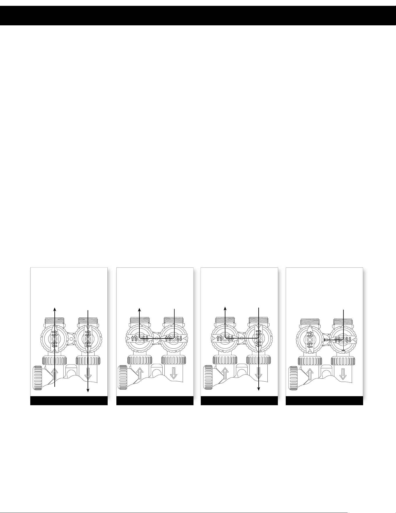
BYPASS POSITION DIAGNOSTIC POSITION SHUT OFF POSITION
FIGURE 1
SUPPLY
WATER EXITS
SUPPLY
WATER ENTERS
FIGURE 3
SUPPLY
WATER EXITS
SUPPLY
WATER ENTERS
FIGURE 2
NO
WATER EXITS
SUPPLY WATER IS
SHUT OFF
TO THE HOUSE
AND THE VALV E
FIGURE 4
BYPASS VALVE
The bypass valve is typically used to isolate the control valve from the plumbing system’s water pressure in order to perform control
valve repairs or maintenance. The 1” full flow bypass valve incorporates four positions, including a diagnostic position that allows a
service technician to have pressure to test a system while providing untreated bypass water to the building. Be sure to install bypass
valve onto main control valve before beginning plumbing or make provisions in the plumbing system for a bypass. The bypass body and
rotors are glass-filled Noryl® and the nuts and caps are glass-filled polypropylene. All seals are self-lubricating EPDM to help prevent
valve seizing after long periods of non-use. Internal “O” Rings can easily be replaced if service is required.
The bypass consists of two interchangeable plug valves that are operated independently by red arrow shaped handles. The handles
identify the direction of flow. The plug valves enable the bypass valve to operate in four positions.
1. NORMAL OPERATION POSITION: The inlet and outlet handles point in the direction of flow indicated by the engraved
arrows on the control valve. Water flows through the control valve for normal operation of a water softener or filter. During the
regeneration cycle this position provides regeneration water to the unit, while also providing untreated water to the distribution
system (Fig. 1).
2. BYPASS POSITION: The inlet and outlet handles point to the center of the bypass. The system is isolated from the water
pressure in the plumbing system. Untreated water is supplied to the building (Fig. 2).
3. DIAGNOSTIC POSITION: The inlet handle points toward the control valve and the outlet handle points to the center of bypass
valve. Untreated supply water is allowed to flow to the system and to the building, while not allowing water to exit from the system
to the building (Fig. 3). This allows the service technician to test the unit and perform other functions without disrupting the water
going to the building.
NOTE: The system must be rinsed before returning the bypass valve to the normal position.
4. SHUT OFF POSITION: The inlet handle points to the center of the bypass valve and the outlet handle points away from the
control valve. The water is shut off to the building. The water treatment system will depressurize upon opening a tap in the building.
A negative pressure in the building combined with the unit being in regeneration could cause a siphoning to the building. If water
is available on the outlet side of the unit, it is an indication of water bypassing the system (Fig. 4) (i.e. a plumbing cross-connection
somewhere in the building).
Bypass Valve

5
INSTALLATION
GENERAL INSTALLATION & SERVICE WARNINGS
The control valve, fittings and/or bypass are designed to accommodate minor plumbing misalignments. There is a small amount of “give”
to properly connect the piping, but the water filter is not designed to support the weight of the plumbing.
Do not use Vaseline
®
, oils, other hydrocarbon lubricants or spray silicone anywhere. A silicone lubricant may be used on black “O” Rings,
but is not necessary. Avoid any type of lubricants, including silicone, on red or clear lip seals.
Do not use pipe dope or other sealants on threads. Teflon
®
tape must be used on the threads of the 1” NPT inlet and outlet, the brine line
connection at the control valve, and on the threads for the drain line connection. Teflon
®
tape is not used on the nut connections or caps
because “O” Ring seals are used. The nuts and caps are designed to be unscrewed or tightened by hand or with the special plastic Service
Wrench, #CV3193-02. If necessary, pliers can be used to unscrew the nut or cap. Do not use a pipe wrench to tighten nuts or caps. Do not
place screwdriver in slots on caps and/or tap with a hammer.
SITE REQUIREMENTS
• water pressure – 25-100 psi • current draw is 0.5 amperes
• water temperature – 33-100°F (0.5-37.7°C) • the plug-in transformer is for dry locations only
• electrical – 115/120V, 60Hz uninterrupted outlet
• the tank should be on a firm level surface (above or below grade)
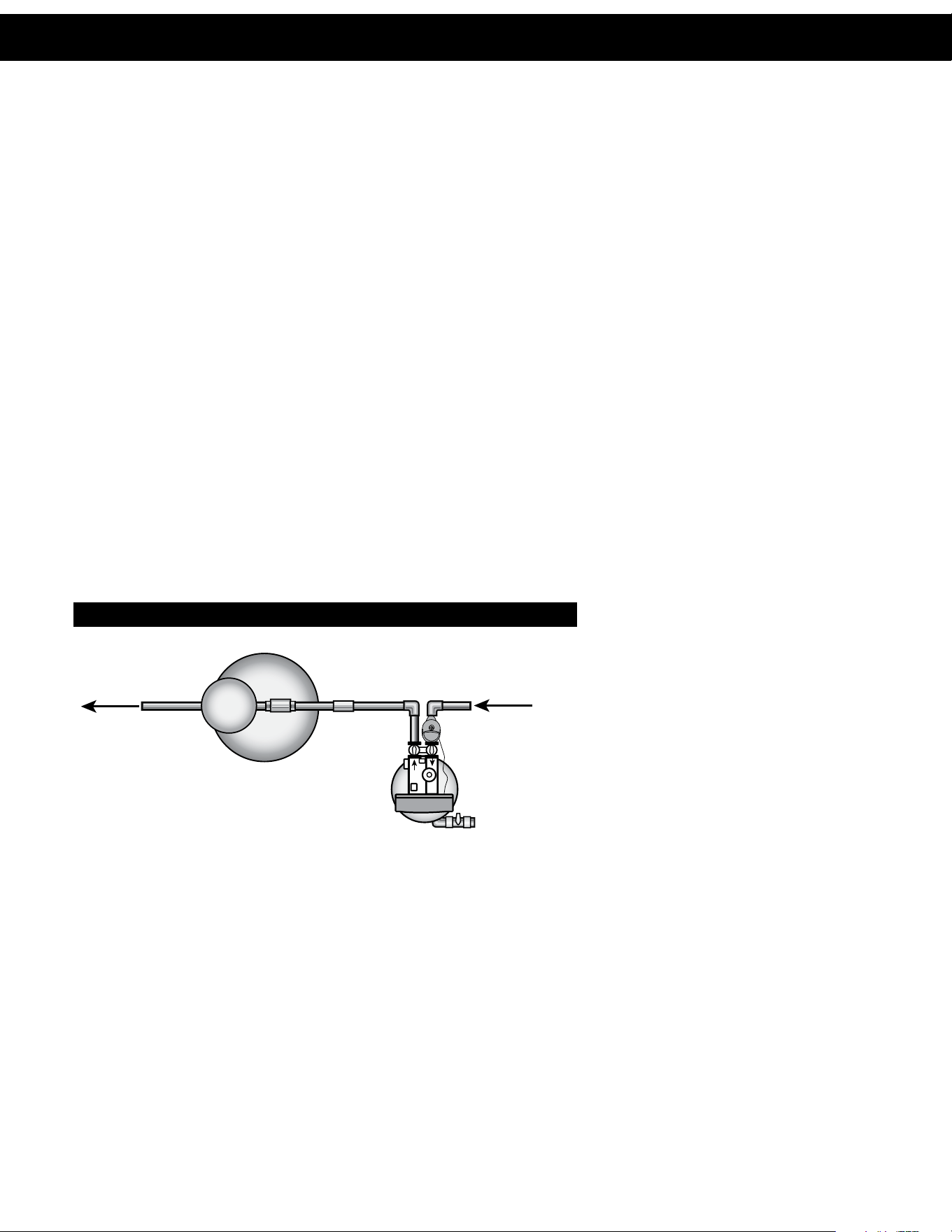
1. STANDARD INSTALLATION CONFIGURATION: There are four different types of regeneration configurations detailed in this
manual: Standard, Clean Water Regeneration, AutoFlush, and Clean Water Regeneration with AutoFlush. The following illustrations
display a standard installation while the following pages display additional installation configurations.
WELL WATER INSTALLATION MUNICIPAL INSTALLATION
Bypass Valve Installation

6
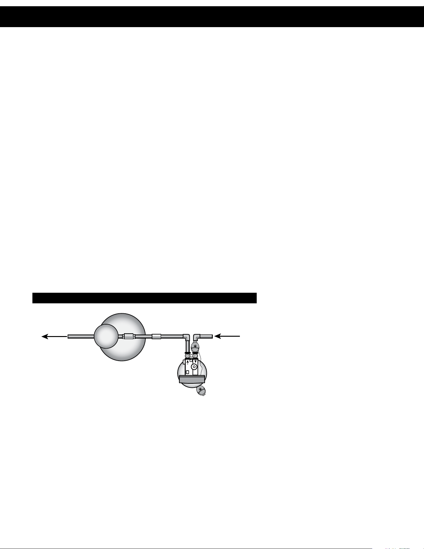
2. STANDARD INSTALLATION WITH
AUTOFLUSH:
The optional AutoFlush kit can be utilized to open the bottom drain automatically. This is operated by using a No Hard Water Bypass (NHBP)
motorized valve and a drive from the control valve. The NHBP can be triggered to open by time and will automatically flush the tank of
debris. This is recommended in some well water conditions where heavy loading of the membranes is likely to occur.
For systems with AutoFlush, follow the instructions accompanying the NHBP. Make sure the drain receptacle can adequately handle the
flow from this line.
AUTOFLUSH INSTALLATION
CAUTION: Never insert a drain line into a drain, sewer line, or trap. Always allow an air gap between the drain line and the
wastewater to prevent the possibility of sewage being back-siphoned into the conditioner.
NOTE: When a NHWB is used in an AutoFlush installation, it is necessary to reverse the wires connected to the board. See the
"Configuring Wires for AutoFlush Connection" section for instructions to confirm or change the wire orientation.
*See additional programming settings section on pages 29-30 of this manual for more information regarding this installation.
The following parts are required for this
installation but are not included with the unit.
• Lower tank shut-off valve
• Spring Assisted Check valve
• No Hard Water Bypass (activated during
regeneration). CV3070FM
INSTALLATION
Installation
7
3. CLEAN WATER REGENERATION
For installations with a high fouling potential, a back flush surge tank and/or a No Hard Water Bypass on the inlet is recommended.
During regeneration, the three way valve will close the normal service inlet and open the inlet from the back flush surge tank. The back
flush surge tank supplies clean, treated water for regeneration. A 50 gallon (total volume) or larger Storage Tank is required. A minimum
of 25 gallons of stored water is required to regenerate the unit.
CLEAN WATER REGENERATION INSTALLATION
The following parts are required for this
installation but are not included with the unit.
• Lower tank shut-off valve
• Spring Assisted Check valve
• No Hard Water Bypass (activated during
regeneration). CV3070FM
CAUTION: The backflush surge tank must be sized to provide enough water for the entire regeneration whether an auto flush kit is
installed or the chlorine generator option is used.
*See additional programming settings section on pages 29-30 of this manual for more information regarding this installation.
NO HARD
WATER BYPASS
(#CV3070FM)
OUTSIDE TAP
WATER
METER
WATER SUPPLY
TREATED
WATER
OUTLET
SHUT-OFF/
DRAIN VA LV E
FRESH
WATER TANK
5
MICRON
FILTER
TREATED
WATER
OUTLET
EXPANSION
TANK
CHECK
VA LV E
GROUND
STRAP
SHUT OFF
VA LV E
RAW WATER
INLET
EXPANSION
TANK
FRESH WATER
TANK
Overhead View
INSTALLATION
Installation Installation
8
4. CLEAN WATER REGENERATION WITH AUTOFLUSH
For installations with a high fouling potential, a back flush surge tank and/or a Separate Source Regeneration Valve (SEPS) or three way
valve on the inlet is recommended. During regeneration, the three way valve will close the normal service inlet and open the inlet from
the back flush surge tank. The back flush surge tank supplies clean, treated water for regeneration. A 50 gallon (total volume) or larger
Storage Tank is required. A minimum of 25 gallons of stored water is required to regenerate the unit.
For systems with AutoFlush, follow the instructions accompanying the NHBP. Make sure the drain receptacle can adequately handle the
flow from this line.
CLEAN WATER REGENERATION AND AUTOFLUSH
TREATED
WATER
OUTLET
RAW WATER
INLET
EXPANSION
TANK
FRESH WATER
TANK
NO HARD
WATER BYPASS
(#CV3070FM)
NO HARD
WATER BYPASS
(AUTOFLUSH)
Overhead View
CAUTION: This backflush surge tank must be sized to provide enough water for the entire regeneration whether an auto flush kit
is installed or the chlorine generator option is used.
NOTE: When a NHWB is used in an AutoFlush installation, it is necessary to reverse the wires connected to the board. See the
"Configuring Wires for AutoFlush Connection" section for instructions to confirm or change the wire orientation.
*See additional programming settings section on pages 29-30 of this manual for more information regarding this installation.
The following parts are required for the listed
installations but are not included with the unit.
• Lower tank shut-off valve
• Spring Assisted check valve (see drawing for
location)
• No Raw Water Bypass x2 (CV3070FM)
– For Clean Water Regen
– For AutoFlush (wires reversed)
INSTALLATION
Installation
9
INSTALLATION
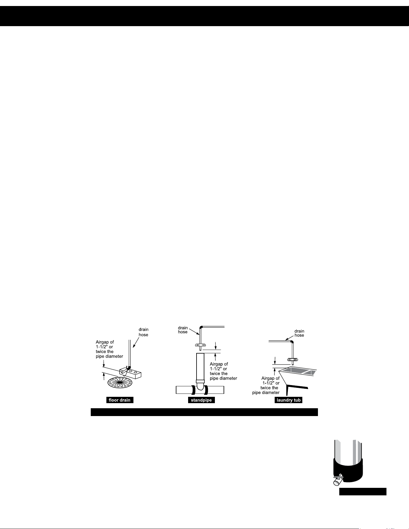
1. The distance between the drain and the water conditioner should be as short as possible. (See Step 8)
2. It is not recommended to install any water conditioner with less than 10 feet of piping between its outlet and the inlet of a water
heater.
3. Do not locate unit where it or its connections (including the drain and overflow lines) will ever be subjected to room temperatures
under 33°F.
4. Do not subject the tank to any vacuum, as this may cause an “implosion” and could result in leaking. If there is a possibility a vacuum could
occur, please make provision for a vacuum breaker in the installation.
5. Installation of a 5 micron pre-filter is recommended before the UF Filter. This will ensure that larger particles will not prematurely foul
the membrane.
6. INLET/OUTLET PLUMBING: Be sure to install Bypass Valve onto main control valve before beginning plumbing. If it is desired to
bypass outside hydrants, a cold water kitchen sink, or other locations, provisions should be made at this time. Install an inlet shutoff
valve and plumb to the unit’s bypass valve inlet located at the right rear as you face the unit. There are a variety of installation fittings
available. They are listed under the Installation Fitting Assemblies section of the manual. When assembling the installation fitting
package (inlet and outlet), connect the fitting to the plumbing system first and then attach the nut, split ring and “O” Ring. Heat from
soldering or solvent cements may damage the nut, split ring or “O” Ring. Solder joints should be cool and solvent cements should be set
before installing the nut, split ring and “O” Ring. Avoid getting solder flux, primer, and solvent cement on any part of the “O” Rings, split rings,
bypass valve or control valve. If the building’s electrical system is grounded to the plumbing, install a copper grounding strap from the inlet to
the outlet pipe. Plumbing must be done in accordance with all applicable local codes.
7. INSTALLING GROUND: To maintain an electrical ground in metal plumbing of a home’s cold
water piping (such as a copper plumbing system), install a ground clamp or jumper wiring. (See
drawing to the right.)
8. CONTROL VALVE DRAIN LINE: First, be sure that the drain can handle the backwash rate of the
system. Solder joints near the drain must be done prior to connecting the drain line flow control fitting.
Leave at least 6” between the drain line flow control fitting and solder joints. Failure to do this could cause
interior damage to the flow control. Install a 1/2” I.D. tube to the Drain Line Assembly in accordance with
plumbing regulations or discard the tubing nut and use the 3/4” NPT fitting for rigid pipe (recommended).
If the backwash rate is greater than 7 gpm, use a 3/4” drain line. Where the drain line is elevated but
empties into a drain below the level of the control valve, form a 7” loop at the discharge end of the line
so that the bottom of the loop is level with the drain connection on the control valve. This will provide
an adequate anti-siphon trap. Piping the drain line overhead <10 ft is normally not a problem. Be sure
adequate pressure is available (40-60 psi is recommended). Where the drain empties into an overhead sewer line, a sink-type trap must be used
with appropriate air gap (see drawing). Run drain tube to its discharge point in accordance with plumbing codes. Pay special attention to codes
for air gaps and anti-siphon devices.
NOTE: Drain line nut will not be supplied for units having a backwash rate greater than 7 gpm.
9
. BOTTOM OF TANK DRAIN CONNECTION: At the bottom of the tank is a 1” male threaded connection
fitting. This connection should be fitted with a ball valve. IMPORTANT – the 1” connection is wide open and will
require a ball valve. A drain line should then be run to the nearest drain location. The ball valve is in the closed
position and opened manually to periodically blow the tank down of debris. This should be done manually at
least once per month or if a pressure drop is noticed across the system.
NOTE: The manufacturer does not include the ball valve or drain line – this needs to be supplied and installed
by the dealer or installer.
bottom drain port
TYPICAL DRAIN LINE INSTALLATIONS
bottom drain port
Installation Installation
10
INSTALLATION
10. CONFIGURING CONNECTION WIRES FOR AUTOFLUSH
In order to use the NHWB in an AutoFlush con gura on, it is rst required to reverse the orienta on of the wires in the plas c
connector.
Step 1: Posi on the end of the connector so that the "ears" are facing up (see illustra on below). Con rm that the wire on the le is
white. This is the standard orienta on. Flip the connector over.
Step 2: Using a thin tool (a at blade or thumbtack), press gently on the middle of both of the metal terminals while pulling down
slightly on the wires. The wires will release from the plas c connector.
Step 3: Reverse the orienta on of the wires and slide both terminals back into the plas c connector. Con nue sliding in wires un l
they click into place.
While looking at the front of the connector (the "ear" side), the white wire will now be on the right. The NHWB is now
correctly con gured for use in an AutoFlush installa on.
1
2
3
11. CONNECTING NO HARD WATER BYPASS (NHWB) TO BOARD
For a No Hard Water Bypass used in a Clean Water Regenera on con gura on, connect to the "Drive 2" (Yellow) molex
connector. Ensure that the wires are in the Standard Con gura on (white on le ).
For a No Hard Water Bypass used in an AutoFlush con gura on, connect to the "Drive 1" (Brown) molex connector. Ensure that the
wires are in the "AutoFlush" Con gura on (white on right).
4
Press
Gently
Pull
Down
Bring white wire to
left side
Push wires back
into connector
until they click
into place
Drive 1
(Brown)
Piston Rod
Drive 2
(Yellow)
Motor
(White)
"Standard"
Con guration
"AutoFlush"
Con guration
Installation
11
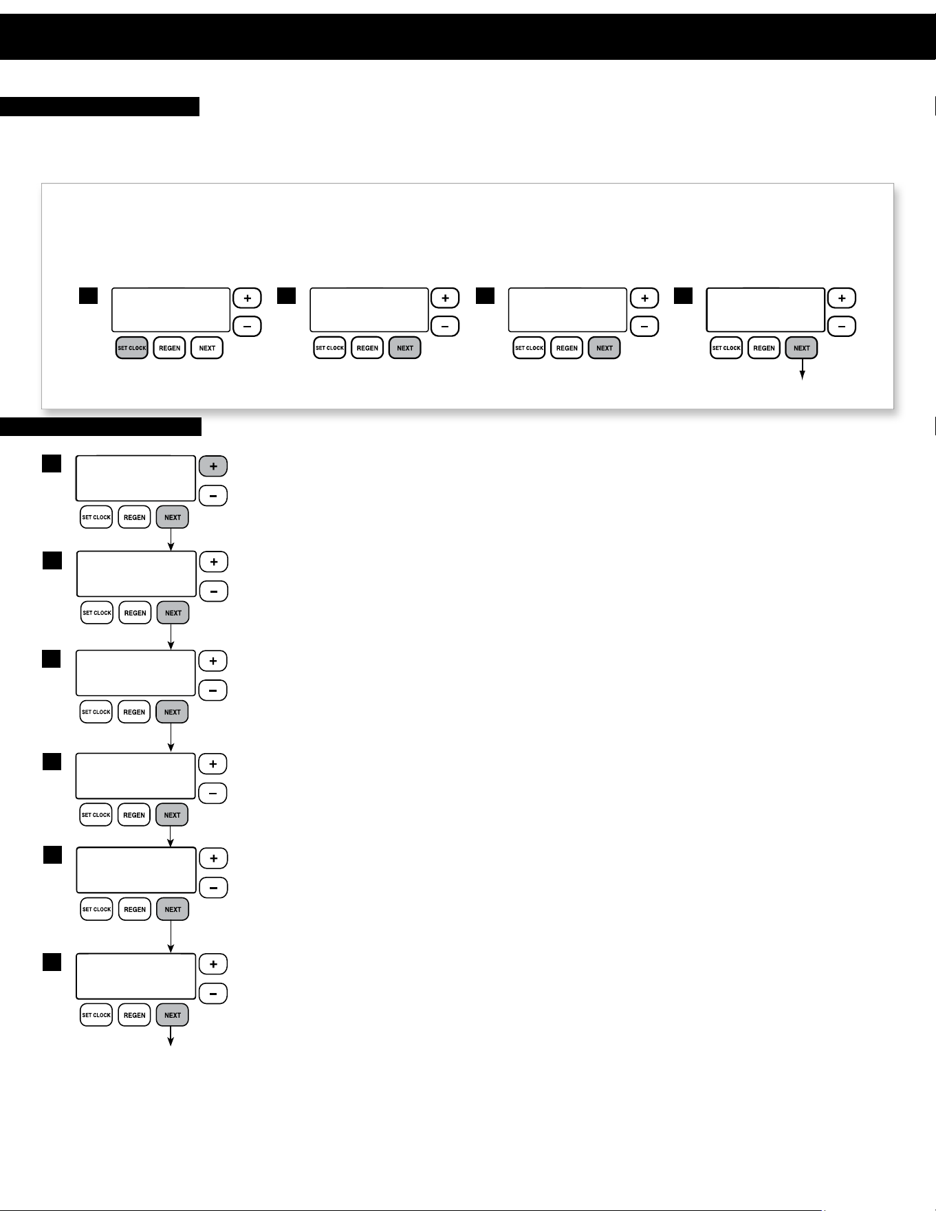
PROGRAMMING PROCEDURES
1
TIME HOUR
AM
SET
2:00
TIME MINUTES
AM
SET
2:00
2 3
CURRENT DAY
SET
MON
4
Return to general display.
1
2
REGEN TIME HOUR
AM
SET
12:00
3
REGEN TIME MINUTES
AM
SET
12:00
4
LIGHT NORMALLY
SET
ON
8
Return to general display.
5
6
7
REGENS PER DAY
SET
1 PER
SERVICE ALARM
SET
OFF
SERVICE ALARM
SET
OFF
YR
GAL
ALARM BUZZER START
SET
ALARM BUZZER END
SET
6:00
AM
10:00
PM
ALARM BUZZER
SET
OFF
Typically, time of day should only need to be set after extended power outages, when daylight saving time begins or ends, or after the battery
has been replaced. If an extended power outage occurs, the time of day will flash on and off indicating that the time should be reset and
battery replaced (See Operating/Maintenance Section). To set the clock:
STEP 1 – Press the CLOCK button.
STEP 2 – Set the hour of the day using
+ or – buttons. AM/PM toggles after 12. Press NEXT to go to step 3.
STEP 3 – Set the minutes using
+ or – buttons. Press NEXT to go to step 4 or REGEN to return to previous step.
STEP 4 – Set the day of the week using
+ or – buttons. Press NEXT to exit clock setting or REGEN to return to previous step.
1. Set Time of Day
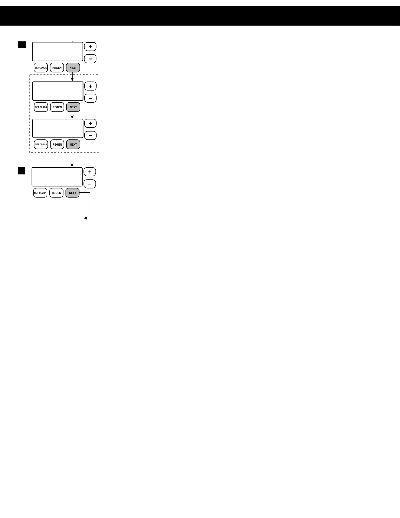
2. Programming
The manufacturer has preset the control valve to back flush once a day, with a 300 Gallon Setting
between regenerations. If 300 gallons are used, the unit will regenerate at the next regeneration time.
STEP 1 – Press and hold the NEXT and
+ buttons simultaneously for 3 seconds.
STEP 2 – REGENS PER DAY: Set the time between regenerations. The manufacturer has set this for once
per day. To change use the
+ or – buttons, toggle the correct amount of regenerations per day
or select “OFF” and press NEXT to advance to days between regeneration. If a specific number of
days between regeneration is desired, press the + or – buttons to toggle to the correct number.
From the day screen, to return back to multiple regenerations in one day, press both the CLOCK
and + buttons at the same time.
STEP 3 – REGENERATION HOUR: Use the
+ or – buttons to adjust the time of day the unit will regenerate.
AM/PM toggles after 12. The manufacturer has factory set 12:00 A.M. as the default setting which is
recommended for a normal household.
STEP 4 – REGENERATION MINUTES: Use the + or – buttons to set minutes.
STEP 5 –
SERVICE ALARM GALLONS: The manufacturer has factory set “OFF” as the default. This feature
is used to signal service into the future. This is typically set by the installing dealer to warn the
homeowner that service is required after a preset number of gallons have been consumed. If the
feature is active, a specific gallon amount will appear.
STEP 6 – SERVICE ALARM TIME: The manufacturer has factory set “OFF” as the default. This feature is used
to signal service into the future. This is typically set by the installing dealer to warn the homeowner
that service is required after a period of time has passed. If the feature is active, a specific number of
days will appear.
con nued on next page
Installation Programming Procedures
12
PROGRAMMING PROCEDURES
1
2
REGEN TIME HOUR
AM
SET
12:00
3
REGEN TIME MINUTES
AM
SET
12:00
4
LIGHT NORMALLY
SET
ON
8
Return to general display.
5
6
7
REGENS PER DAY
SET
1 PER
SERVICE ALARM
SET
OFF
SERVICE ALARM
SET
OFF
YR
GAL
ALARM BUZZER START
SET
ALARM BUZZER END
SET
6:00
AM
10:00
PM
ALARM BUZZER
SET
OFF
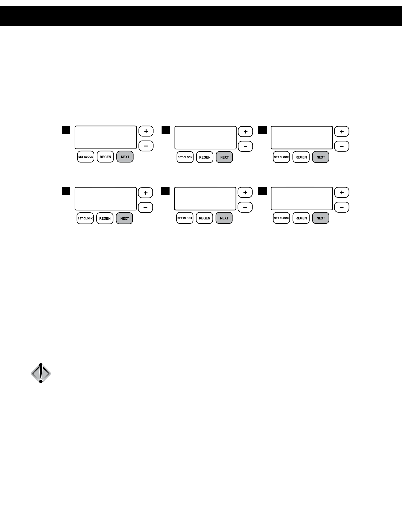
STEP 7 – ALARM BUZZER: Use the + or – buttons to turn the alarm ON or OFF. Unit is set to OFF by default.
Alarm will sound after a regeneration warning the owner of possible valve errors or other issues. This
alarm is a short 0.5 second burst every 3 seconds. When alarm buzzer is set to ON, pressing the NEXT
button proceeds to the Alarm Start Time screen. This feature allows the installer to choose a time when
the owner will be home or awake to hear the alarm.
BUZZER START TIME: Press the + or – buttons to select the hour when the buzzer should begin sounding.
AM/PM toggles after 12. Default setting is 6:00 a.m.
BUZZER STOP TIME: Press the
+ or – buttons to select the hour when the buzzer should stop sounding. AM/
PM toggles after 12. Default setting is 10:00 p.m.
STEP 8 – DISPLAY BACKLIGHT: The manufacturer has factory set “ON” as the default. Turn the light
“OFF” or “ON” using the
+ or – buttons. “OFF”
will turn display backlight off after five minutes of keypad inactivity.
Press NEXT to exit installer programming.
Programming Procedures

13
STARTUP INSTRUCTIONS
The system regeneration sequence for a Standard Installation configuration is in the following order. To change the cycle order, consult
the unit’s Dealer Manual or contact the manufacturer. Please see page 29 for sequences for Autoflush and Clean Water Regeneration
configurations.
Standard Installation Regeneration Sequence:
1. Backwash (2 minutes)
2. Rinse (1 minute)
The system is now ready for filling with water and for testing.
1. With the UF Filter Control Valve in bypass mode and unplugged (Fig. 2 on page 4) turn water on slowly. Water will fill system (not the
membrane tank) including the pre-filter and post storage tank if used. Run water preferably at a laundry sink or tub faucet and allow
plumbing to clear. Check for any leaks at this time in newly installed plumbing.
2. With the UF Filter Control Valve in bypass mode (Fig. 2 on page 4) plug control valve transformer into a permanent 110 volt outlet.
The valve should be in normal operating mode where the display shows either time of day or gallons remaining. Press and hold the
����� button until the motor starts. The display will indicate the unit is in the regeneration mode. Release the button.
3. The unit is now in backwash position as indicated on the control valve screen. Do not turn the water on.
4. Push ����� button to advance the control valve to the rinse position. Once the valve enters the rinse position, unplug from receptacle.
Leaving the valve in this position, open the inlet bypass valve to the system slowly. This will allow water to enter the tank slowly and
flush the air to the drain. Once system is full, a steady stream of water will be observed at the drain. Open inlet bypass valve completely
(Fig. 3 on page 4) and allow water to drain for 20 minutes. This will allow for proper flushing of the membrane and any preservatives
used in the manufacturing and storage process.
5. Plug unit back into the receptacle.
6. Push ����� button and system will return to the normal service position.
7. Again, follow steps 2–6 with the bypass inlet valve open. This will allow for any additional air to be dispelled from the system. It is not
necessary to flush for 20 minutes again as in step 4. When or if no air is observed at the drain, proceed to step 8.
8. Advance control valve to the service position. Upon returning to the service position, open the outlet valve of the bypass to the normal
operating position.
NOTE: Bypass valves should be in the normal operation position. (Fig.1 on page 4).
9. Open a faucet at a laundry sink or at a bath tub. Water will now be flowing through the UF filter system. Run system until water is
clear.
NOTE: If a back flush tank is being used, this will need to be isolated during startup to ensure that no disinfection chemicals enter the
tank. This could cause premature failure of the tank.
NOTE: If a SEP (Separate Source Regen Kit) or a NHBP (No Hard Water Bypass Kit) will be used, these should be left in the normally service
position and disconnected during start up.
NOTE: If an Auto Flush Kit is being used, it should be in the normally closed position during start up.
Start-up Procedures
14
OPERATING DISPLAYS AND MAINTENANCE
1. GENERAL OPERATION: When the system is operating, one of six displays may be shown and will alternate with the installing dealer’s name
and phone number for future service (if set). Pressing NEXT will alternate between the displays.
1. Time of Day Screen: Displays the current time of day, the day of the week, and flow rate.
2. Flow Rate Screen: Displays the current treated water flow rate through the system in Gallons Per Minute.
3. Vacation Mode Screen: Allows the system to be “shut down” when there will be no water usage for an extended period of time.
4. Capacity Remaining Screen: Displays the amount of gallons of treated water remaining until the system triggers a regeneration.
5. Days to a Regen Screen: Displays the number of days until the system triggers a regeneration. Based on the days override value.
6. Dealer Name Screen: Displays dealer specific name and phone number. This scrolling display will only appear if set by the dealer.
If the system has called for a regeneration that will occur at the preset time of regeneration, the words “REGEN TODAY” will appear on the display.
If a water meter is installed, “GPM” flashes on the display when water is being treated, indicating gallons per minute flowing through the system.
2. VACATION MODE: This feature may be used to “shut down” the system for a period of time by preventing the unit from regenerating. The
manufacturer has factory set “OFF” as the default. Turn feature “OFF” or “ON” using the
+ or – buttons. When turned “ON”, the unit will remain
in Vacation Mode until it is exited. There are two ways that a unit can exit Vacation Mode:
Manually: The user may manually exit Vacation Mode by changing the setting from “ON” to “OFF”. Once switched off, a delayed
regeneration will queue for that night. Vacation mode may also be manually exited by holding the REGEN button to force an immediate
regeneration.
Automatically: The unit will automatically exit Vacation Mode once water usage has resumed. After fifty gallons of water is used, the unit
will set to resume normal operation and a delayed regeneration will queue for that night.
NOTE: In some instances, if a regeneration has been queued and the unit is taken out of Vacation Mode (manually or automatically),
the unit will trigger an immediate regeneration instead of a delayed regeneration. For example, if the unit’s maximum Days
Between Regeneration is reached while the unit is in Vacation Mode, an immediate regeneration will trigger as soon as the unit
is taken out of Vacation Mode.
CAUTION: Depending on the severity of water conditions and the length of no water usage, it may not be recommended to use this
feature. Please contact dealer or manufacturer for more information.
TIME OF DAY MON
GPM
2:408
PM
FLOW RATE
GPM
8.0
ON VACATION
NO
CAPACITY REMAINING
GPM GAL
300
8
DAYS TO A REGEN
GPM
1
8
PHONE NUMBER
DEALER NA
1
4
2
2
5
3
6
Operation & Maintenance
15
OPERATING DISPLAYS AND MAINTENANCE
OPERATING DISPLAYS AND MAINTENANCE
3. Regeneration Mode: Standard UF Filters are set to regenerate once a day. This is a short (2
minute) back flush of the membrane. If water is used at this time, it may be possible to notice
untreated water in the system. If this becomes an issue please contact dealer as options are
available to alleviate this. When the system begins to regenerate, the display will include
information about the step of the regeneration process and the time remaining for that step
to be completed. The system runs through the steps automatically and will reset itself to provide
treated water when the regeneration has been completed.
4. MANUAL REGENERATION: Sometimes there may be a need to regenerate a unit before the control
valve calls for it. This may be needed if a period of heavy water use is anticipated or when the system has been
operating without salt.
• To initiate a manual regeneration at the next preset regeneration time, press and release the REGEN
button. The words “REGEN TODAY” will flash on the display to indicate that the system will regenerate
at the scheduled regeneration time (see the Programming Procedures section). If you pressed the
REGEN button in error, pressing and releasing the button again will cancel the command.
• To initiate a manual regeneration immediately, press and hold the REGEN button for three seconds.
The system will begin to regenerate immediately. This command cannot be canceled.
On Standard UF Filters once a manual regeneration is initiated, the unit will proceed to the backwash position. In this position a two
minute flush to the drain will occur. This backwash allows for flushing of particulates from the membrane to the drain. Once this is
complete, the unit transfers to a one minute rinse. This rinses the tank of these same particles.
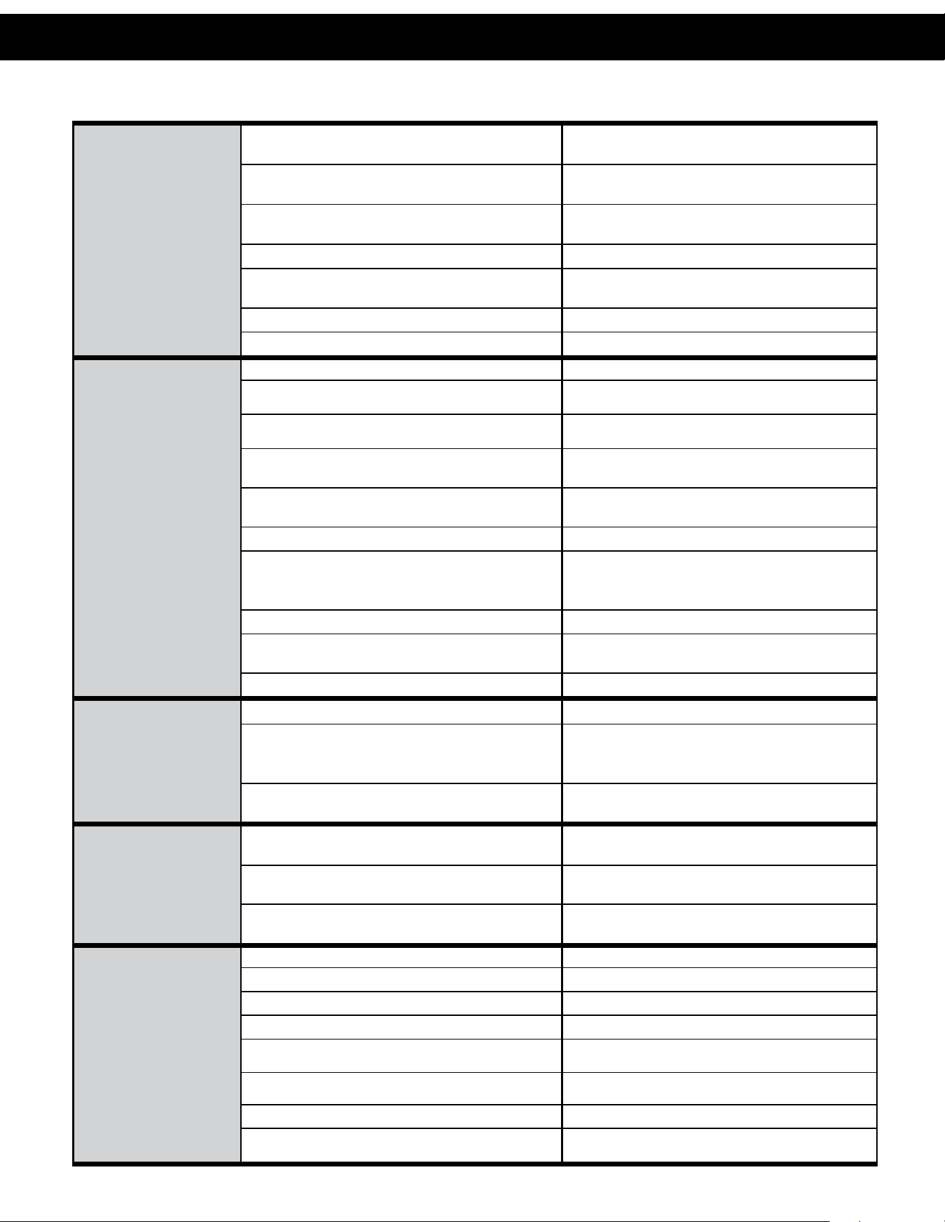
5. POWER LOSS AND BATTERY REPLACEMENT: If an extended power outage occurs, the control
valve will retain the time of day settings until the board’s battery is depleted. Once the battery is
depleted, the display will appear dark and absent of any information. If this occurs, following these steps
will determine if the problem is a low battery or a board failure.
To determine if the battery is depleted:
1. Remove valve cover. Disconnect power from PC Board at the four pin connector at the bottom
of the board.
2. Wait five minutes for board to de-energize. Remove battery with a non-conductive/non-metallic
material. Reference the Parts Breakdown section of this manual for location.
3. Wait five minutes for board to de-energize.
4. With the battery out, re-connect the power supply to the board. The board’s display should
begin to show information.
This indicates that the board is operating correctly. If the display does not work, call installing dealer for service.
5. To replace with new battery, unplug transformer from outlet. Install a 3 volt Lithium Coin Cell type 2032 battery, available at most
stores. Plug unit back into outlet.
It is important to replace the battery with the valve unplugged to avoid causing a short and potentially ruining the board.
6. Reset the time of day (see programming procedures) and initiate regeneration (see operating displays and maintenance).
If these procedures do not remedy the problem, please consult the installing dealer for service.
6. AUDIBLE ALARM: This control valve is equipped with an audible alarm and visual alarm. This alarm is set by the installing dealer and is used to
warn the owner of possible valve errors or other issues.
To turn off alarm: If the audible alarm sounds, press any button on the face of the control valve to turn off and call the dealer for service.
7. ERROR MESSAGE: If the word “ERROR” appears and flashes alternately with the dealer name and phone
number, record the ERROR number and contact your servicing dealer promptly. This indicates that the control
valve was not able to function properly.
REGENERATION MODE
BACKWASH
8:22
Current Regen
Cycle Stage
Time Remaining
in Stage
MANUAL REGEN
REGEN TODAY MON
GPM
2:408
PM
REGEN TODAY and TIME OF DAY
will ash alternately if a regeneration
is expected tonight.
BATTERY REPLACEMENT
ERROR SCREEN
ERROR
106
CALL FOR SERVICE
Operation & Maintenance Operation & Maintenance
16
PROBLEM CAUSE CORRECTION
1. No display on
PC board.
A. Depleted battery. A. See Operating Display and Maintenance section.
B. Control valve power adapter not plugged into outlet
or power cord end not connected to PC board
connection.
B. Plug power adapter into outlet or connect
power cord end to PC board connection.
C. Improper power supply.
C. Verify proper voltage is being delivered to
PC board.
D. Defective power adapter. D. Replace power adapter.
E. Defective PC board. E. Replace PC board.
F. No power at electric outlet.
F. Repair outlet or use working outlet.
2. PC board does not
display correct time
of day.
A. Power adapter plugged into electric outlet controlled
by light switch.
A. Use uninterrupted outlet.
B. Tripped breaker switch and/or tripped GFI. B. Reset breaker switch and/or GFI switch.
C. Power outage.
C. Reset time of day. If PC board has battery
back up present the battery may be depleted. See
front cover and drive assembly drawing
for instructions.
D. Defective PC board. D. Replace PC board.
3. Display does not
indicate that water is
flowing. Refer to user
instructions for how
the display indicates
water is flowing.
A. Bypass valve in bypass position.
A. Turn bypass handles to place bypass in
service position.
B. Meter is not connected to meter connection on PC
board.
B. Connect meter to three pin connection labeled
METER on PC board.
C. Restricted/stalled meter turbine.
C. Remove meter and check for rotation or
foreign material.
D. Meter wire not installed securely into three
pin connector.
D. Verify meter cable wires are installed securely into
three pin connector labeled METER.
E. Defective meter. E. Replace meter.
F. Defective PC board. F. Replace PC board.
4. Control valve
regenerates at wrong
time of day.
A. Power outage.
A. Reset time of day. If PC board has battery
back up present the battery may be depleted. See
front cover and drive assembly drawing
for instructions.
B. Time of day not set correctly. B. Reset to correct time of day.
C. Time of regeneration set incorrectly. C. Reset regeneration time.
D. Control valve set at immediate regeneration.
D. Check programming setting and reset to DELAYED
(for a delayed regen time).
5. Time of day flashes on
and off.
A. Power outage.
A. Reset time of day. If PC board has battery
back up present the battery may be depleted. See
front cover and drive assembly drawing
for instructions.
6. Control valve does
not regenerate
automatically when
the correct button(s) is
pressed and held.
For timeclock valves
the buttons are
+ or –.
For all other valves the
button is REGEN.
A. Broken drive gear or drive cap assembly. A. Replace drive gear or drive cap assembly.
B. Broken piston rod. B. Replace piston rod.
C. Defective PC board. C. Defective PC board.
D. Cover installed incorrectly. D. Reinstall cover.
TROUBLESHOOTING GUIDE
Troubleshooting Guide
17
7. Control valve does
not regenerate
automatically but
does when the correct
button(s) is depressed
and held. For
timeclock valves the
buttons are
+ or –.
For all other valves the
button is REGEN.
A. Bypass valve in bypass position.
A. Turn bypass handles to place bypass in
service position.
B. Meter is not connected to meter connection on PC
board.
B. Connect meter to three pin connection labeled
METER on PC board.
C. Restricted/stalled meter turbine.
C. Remove meter and check for rotation or
foreign material.
D. Incorrect programming. D. Check for programming error.
E. Meter wire not installed securely into three
pin connector.
E. Verify meter cable wires are installed securely into
three pin connector labeled METER.
F. Defective meter. F. Replace meter.
G. Defective PC board. G. Replace PC board.
8. Hard or untreated
water is being
delivered.
A. Bypass valve is open or faulty. A. Fully close bypass valve or replace.
B. Media is exhausted due to high water usage.
B. Check program settings or diagnostics for abnormal
water usage.
C. Meter not registering.
C. Remove meter and check for rotation or
foreign material.
D. Water quality fluctuation.
D. Test water and adjust program
values accordingly.
E. No regenerant or low level of regenerant in
regenerant tank.
E. Add proper regenerant to tank.
F. Control fails to draw in regenerant. F. Refer to Troubleshooting Guide number 12.
G. Insufficient regenerant level in regenerant tank.
G. Check refill setting in programming. Check refill
flow control for restrictions or debris and, if
necessary, replace.
H. Damaged seal/stack assembly/piston. H. Replace seal/stack assembly and/or piston.
I. Control valve body type and piston type
mix matched.
I. Verify proper control valve body type and
piston type match.
J. Fouled media bed. J. Replace media bed.
9. Control valve uses
too much regenerant.
A. Improper refill setting. A. Check refill setting.
B. Improper program settings.
B. Check program setting to make sure
they are specific to the water quality and
application needs.
C. Control valve regenerates frequently.
C. Check for leaking fixtures that may be exhausting
capacity or system is undersized.
10. Residual regenerant
being delivered to
service.
A. Low water pressure.
A. Check incoming water pressure – water pressure
must remain at minimum of 25 psi.
B. Incorrect, damaged, or restricted injector.
B. Replace injector with correct size for
the application.
C. Restricted drain line.
C. Check drain line for restrictions or debris
and remove any obstructions.
11. Excessive water in
regenerant tank.
A. Improper program settings. A. Check refill setting.
B. Plugged injector. B. Remove injector and replace.
C. Drive cap assembly not tightened in properly. C. Re-tighten the drive cap assembly.
D. Damaged seal/stack assembly/piston. D. Replace seal/stack assembly and/or piston.
E. Restricted or kinked drain line.
E. Check drain line for restrictions or debris and or
unkink drain line.
F. Plugged backwash flow controller.
F. Remove backwash flow controller and replace, if
necessary.
G. Missing refill flow controller. G. Install refill flow controller.
H. Brine tube not inserted properly into brine elbow in
brine tank.
H. Install tube all the way into elbow.
PROBLEM CAUSE CORRECTION
TROUBLESHOOTING GUIDE
Troubleshooting Guide Troubleshooting Guide
18
TROUBLESHOOTING GUIDE
12. Control valve fails to
draw in regenerant.
A. Injector is plugged. A. Remove injector and replace.
B. Faulty regenerant piston. B. Replace regenerant piston.
C. Regenerant line connection leak. C. Inspect regenerant line for air leak.
D. Drain line restriction or debris cause excess back
pressure.
D. Inspect drain line and remove to
correct restriction.
E. Drain line too long or too high. E. Shorten length and or height.
F. Low water pressure.
F. Check incoming water pressure – water
pressure must remain at minimum of 25 psi.
13. Water running to
drain.
A. Power outage during regeneration.
A. Upon power being restored control will finish
the remaining regeneration time. Reset time of
day. If PC board has battery back up present the
battery may be depleted. See front cover and drive
assembly drawing for instructions.
B. Damaged seal/stack assembly. B. Replace seal/stack assembly.
C. Piston assembly failure. C. Replace piston assembly.
D. Drive cap assembly not tightened in properly. D. Re-tighten the drive cap assembly.
14. E1, Err – 1001,
Err – 101 =
Control unable
to sense motor
movement.
A. Motor not inserted full to engage pinion, motor
wires broken or disconnected.
A. Disconnect power, make sure motor is fully engaged,
check for broken wires, make sure
two pin connector on motor is connected to the two
pin connection on the PC board labeled MOTOR.
Press NEXT and REGEN buttons for
3 seconds to resynchronize software with piston
position or disconnect power supply from PC board
for 5 seconds and then reconnect.
B. PC board not properly snapped into drive bracket.
B. Properly snap PC board into drive bracket and
then Press NEXT and REGEN buttons for 3 seconds
to resynchronize software with piston position
or disconnect power supply from PC board for 5
seconds and then reconnect.
C. Missing drive gears. C. Replace missing gears.
D. Motor does not drive/run. D. Replace motor.
E. Viewing eye or encoder is blocked or damaged.
E. clear viewing eye on board, on drive bracket, or
replace PC board if no debris is found.
15. E2, Err – 1002,
Err – 102 = Excessive
Motor Draw.
A. Foreign material is lodged in control valve.
A. Open up control valve and pull out piston assembly
and seal/stack assembly for inspection. Press NEXT
and REGEN buttons for
3 seconds to resynchronize software with piston
position or disconnect power supply from PC board
for 5 seconds and then reconnect.
B. Mechanical binding.
B. Check piston and seal/stack assembly, check
reduction gears, check drive bracket and main drive
gear interface. Press NEXT and REGEN buttons for
3 seconds to resynchronize software with piston
position or disconnect power supply from PC board
for 5 seconds and then reconnect.
C. Drive cap too loose. C. Completely tighten drive cap assembly.
D. Drive cap not “clicked” into backplate.
D. Verify that backplate is properly “clicked” into
place.
PROBLEM CAUSE CORRECTION
Troubleshooting Guide
19
16. E3, Err – 1003,
Err – 103 = Control
valve motor ran
too long and was
unable to find the
next cycle position.
A. Drive bracket not snapped in properly and out
enough that reduction gears and drive gear do not
interface.
A. Snap drive bracket in properly then Press
NEXT and REGEN buttons for 3 seconds to
resynchronize software with piston position
or disconnect power supply from PC board
for 5 seconds and then reconnect.
17. E4, Err – 1004,
Err – 104 = Control
valve motor ran too
long and timed out
trying to reach home
position.
A. Drive bracket not snapped in properly and out enough
that reduction gears and drive gear do
not interface.
A. Snap drive bracket in properly then Press
NEXT and REGEN buttons for 3 seconds to
resynchronize software with piston position
or disconnect power supply from PC board
for 5 seconds and then reconnect.
B. Piston not connected to drive cap. B. Connect or replace (if damaged) piston/drive cap.
18. Err – 1006, Err – 106,
Err – 116 = MAV/
SEPS/ NHBP/ AUX
MAV valve motor
ran too long and
unable to find
the proper park
position.
●Motorized Alternating Valve = MAV
●Separate Source = SEPS
●No Hard Water Bypass = NHBP
●Auxiliary MAV = AUX MAV
A. Control valve programmed for ALT A or B,
nHbP, SEPS, or AUX MAV with out having
a MAV or NHBP valve attached to operate
that function.
A. Press NEXT and REGEN buttons for 3 seconds
to resynchronize software with piston position
or disconnect power supply from PC board for
5 seconds and then reconnect. Then reprogram valve
to proper setting.
B. MAV/NHBP motor wire not connected to
PC board.
B. Connect MAV/NHBP motor to PC board two pin
connection labeled DRIVE. Press NEXT and REGEN
buttons for 3 seconds to resynchronize software
with piston position or disconnect power supply
from PC board for 5 seconds
and then reconnect.
C. MAV/NHBP motor not fully engaged with reduction
gears.
C. Properly insert motor into casing, do not force into
casing Press NEXT and REGEN buttons for
3 seconds to resynchronize software with piston
position or disconnect power supply from PC board
for 5 seconds and then reconnect.
D. Foreign matter built up on piston and stack
assemblies creating friction and drag enough
to time out motor.
D. Replace piston and stack assemblies. Press NEXT
and REGEN buttons for 3 seconds to resynchronize
software with piston position
or disconnect power supply from PC board
for 5 seconds and then reconnect.
19. Err – 1007, Err –
107, Err – 117 =
MAV/ SEPS/NHBP/
AUX MAV valve
motor ran too short
(stalled) while
looking for proper
park position.
●Motorized Alternating Valve = MAV
●Separate Source = SEPS
●No Hard Water Bypass = NHBP
●Auxiliary MAV = AUX MAV
A. Foreign material is lodged in
MAV/NHBP valve.
A. Open up MAV/NHBP valve and check piston and
seal/ stack assembly for foreign material. Press NEXT
and REGEN buttons for 3 seconds
to resynchronize software with piston position
or disconnect power supply from PC board for
5 seconds and then reconnect.
B. Mechanical binding.
B. Check piston and seal/stack assembly, check
reduction gears, drive gear interface, and check
MAV/NHBP black drive pinion on
motor for being jammed into motor body.
Press NEXT and REGEN buttons for 3 seconds to
resynchronize software with piston position or
disconnect power supply from PC board for 5
seconds and then reconnect.
PROBLEM CAUSE CORRECTION
TROUBLESHOOTING GUIDE
Troubleshooting Guide Troubleshooting Guide
20
PROBLEM CAUSE CORRECTION
20. Err – 201
200 errors are only
viewable in history
screens. These do not
flash when error occurs.
A. Invalid regeneration cycle step detected. A. Replace PC board.
21. Err – 202
200 errors are only
viewable in history
screens. These do not
flash when error occurs.
A. Short power disruption. A. Check transformer voltage and verify power source.
B. Foreign material dislodged. B. Check piston and stack for damage.
22. Err – 204 = Leak
detected
200 errors are only
viewable in history
screens. These do not
flash when error occurs.
A. Occurs when dP input is active for “ALARM” and the
input is closed. The alarm buzzer will activate and the
screen will display the error.
A. Check for low flow leak. Press NEXT and REGEN
buttons for 3 seconds to resynchronize software
with piston position or disconnect power supply
from PC Board for 5 seconds
and then reconnect to clear error.
23. Err – 400
*
Memory Errors
*All 400 errors pertain to
memory related errors.
400 and 200 errors are
only viewable in history
screens. These do not
flash when error occurs.
A. Depleted Battery. A. See Operating Display and Maintenance section.
B. Defective PC Board. B. Replace PC board.
TROUBLESHOOTING GUIDE
Troubleshooting Guide
21
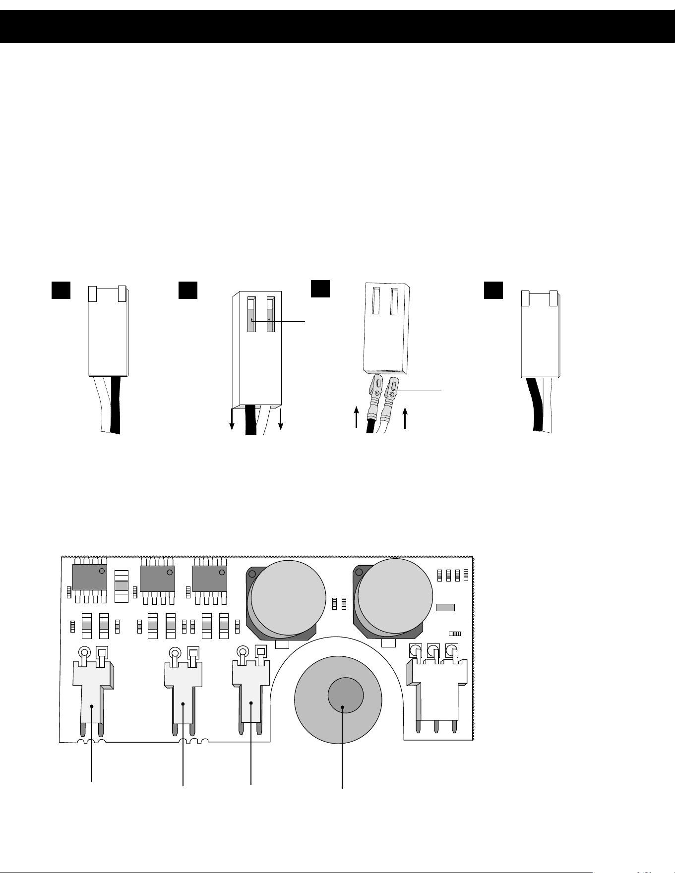
REPLACEMENT PARTS:
2
1
3
5
4
6
FRONT COVER AND DRIVE ASSEMBLY
Item # Part # Description Qty.
1 CV3540-NOLAB Black cover 1
2 CV3107-01 Motor Assembly 1
3 CV32002-A Drive assembly (includes #5 and #6) 1
4 CV4022WU PC board (standard) 1
5 CV3110 Drive gear, 12 x 36 3
6 CV3109 Drive gear cover 1
not
shown
CV3186 Transformer, 110V-12V, AC (standard) 1
CV3543 Optional weather cover 1
NOTE: Battery Location
Replacement Parts
22
REPLACEMENT PARTS
PISTON ASSEMBLY
Item # Part # Description Qty.
1
CV3005-02 1” spacer stack assembly 1
CV3430-01 1.25” spacer stack assembly 1
2 CV3004 Drive cap assembly 1
3 CV3135 O-ring 228 (drive cap o-ring) 1
4
CV3011 1” piston assembly downflow 1
CV3011-01 1” piston assembly upflow 1
CV3407 1.25” piston assembly downflow 1
5 CV3174 Regenerant piston 1
6-12 CV3015 WS1 QC2 tank adapter assembly (includes O-rings) 1
13
CV3001-04 1” body assembly downflow 1
CV3001UP 1” body assembly upflow 1
CV3020 1.25” body assembly downflow 1
14 CV3541 Drive backplate 1
UF REPLACEMENT TANK
Item No. Part No. Description Qty.
1 680842XBBK00UF0 Poly–UF Replacement Tank 1
1
BYPASS VALVE
Item No. Part No. Description Qty.
1 CV3006 Bypass assembly 1
2 CV3147 Bypass handles 2
REPLACEMENT PARTS
Although no tools are necessary to assemble or
disassemble the valve, the Service Wrench, (shown
in various positions on the valve) is available to aid in
assembly or disassembly.
SERVICE WRENCH - CV3193-02
Loosens Injector And
Bypass Caps
Loosens Drive Cap
Replacement Parts
23
UF REPLACEMENT TANK
Item No. Part No. Description Qty.
1 680842XBBK00UF0 Poly–UF Replacement Tank 1
1
BYPASS VALVE
Item No. Part No. Description Qty.
1 CV3006 Bypass assembly 1
2 CV3147 Bypass handles 2
REPLACEMENT PARTS
Although no tools are necessary to assemble or
disassemble the valve, the Service Wrench, (shown
in various positions on the valve) is available to aid in
assembly or disassembly.
SERVICE WRENCH - CV3193-02
Loosens Injector
And
Bypass Caps
Loosens Drive Cap
Replacement Parts
24
INJECTOR ASSEMBLIES
Item No. Part No. Description Qty.
1 CV3176 Injector cap 1
2 CV3152 O-ring 135 1
3 CV3177-01 Injector screen 1
4 CV3010-1Z Injector assembly plug 1
5
CV3010-1A A injector assembly, black
1
CV3010-1B B injector assembly, brown
CV3010-1C C injector assembly, violet
CV3010-1D D injector assembly, red
CV3010-1E E injector assembly, white
CV3010-1F F injector assembly, blue
CV3010-1G G injector assembly, yellow
CV3010-1H H injector assembly, green
CV3010-1I I injector assembly, orange
CV3010-1J J injector assembly, light blue
CV3010-1K K injector assembly, light green
not shown CV3170 O-ring 011, lower *
not shown CV3171 O-ring 013, upper *
*The injector plug and the injector each use one lower and one upper o-ring
3
1
2
WATER METER AND METER PLUG
Item No. Part No. Description Qty.
1 CV3151 Nut, 1” QC 1
2 CV3003 Meter assembly 1
3 CV3105 O-ring 215 1
4 CV3003-01 Meter plug assembly 1
REPLACEMENT PARTS
Replacement Parts
25
Water
Flow
6
9
Drain
Line
1”
4
1
3
5
7
8
2
Proper DLFC orientation
directs water flow towards
the washer face with
rounded edge.
DRAIN LINE ASSEMBLY 1”
Item No. Part No. Description Qty.
1 CH4615 Elbow locking clip 1
2
CV3166 Drain FTG body 1
1
CV3166-01 FTG flow control body 1
3 CV3167 Drain FTG adapter 1 1
4 CV3163 O-ring 019 1
5 CV3150 Split ring 1
6 CV3151 Nut 1" QC 1
7 CV3105 O-ring 215
8
CV3190-090 9.0 gpm DLFC for 1” elbow
One DLFC
must be
used if 1"
fitting is
used
CV3190-100 10.0 gpm DLFC for 1” elbow
CV3190-110 11.0 gpm DLFC for 1” elbow
CV3190-130 13.0 gpm DLFC for 1” elbow
CV3190-150 15.0 gpm DLFC for 1” elbow
CV3190-170 17.0 gpm DLFC for 1” elbow
CV3190-200 20.0 gpm DLFC for 1” elbow
CV3190-250 25.0 gpm DLFC for 1” elbow
9 CV3008-04 FTG Drain 1" Strt No/Sil 1
REPLACEMENT PARTS
DRAIN LINE ASSEMBLY 3/4”
Item No. Part No. Description Qty.
1 CH4615 Elbow locking clip 1
2 CPKP10TS8-BULK Optional insert, 5/8” tube 1
3 CV3192 Optional nut, 3/4” drain elbow 1
4 CV3158-02 Drain elbow, 3/4” NPT with O-ring 1
5 CV3163 O-ring 019 1
6 CV3159-01 DLFC retainer assembly 1
7
CV3162-007 0.7 DLFC for 3/4” elbow
1
CV3162-010 1.0 DLFC for 3/4” elbow
CV3162-013 1.3 DLFC for 3/4” elbow
CV3162-017 1.7 DLFC for 3/4” elbow
CV3162-022 2.2 DLFC for 3/4” elbow
CV3162-027 2.7 DLFC for 3/4” elbow
CV3162-032 3.2 DLFC for 3/4” elbow
CV3162-042 4.2 DLFC for 3/4” elbow
CV3162-053 5.3 DLFC for 3/4” elbow
CV3162-065 6.5 DLFC for3/4” elbow
CV3162-075 7.5 DLFC for 3/4” elbow
8 CV3331 Drain elbow and retainer assembly
Items 2 and 3, nut and insert are only used with 1/2” I.D. by 5/8”
O.D. polytubing. For other piping material, the 3/4” NPT is used.
Replacement Parts
26
Legacy Part # Current Part # Description Qty.
CV3007 100246197
1” PVC male NPT
elbow assembly
2
Legacy Part # Current Part # Description Qty.
CV3007-01 100246198
3/4” & 1” PVC solvent
elbow assembly
2
Legacy Part # Current Part # Description Qty.
CV3007-02 100246199
1” brass sweat
assembly
2
Legacy Part # Current Part # Description Qty.
CV3007-03 100249846
3/4” brass
sweat assembly
2
Legacy Part # Current Part # Description Qty.
CV3007-12 100249847
3/4” brass shark
bite assembly
2
Legacy Part # Current Part # Description Qty.
CV3007-13 100249848
1” brass shark
bite assembly
2
Legacy Part # Current Part # Description Qty.
CV3007-15 100246200
3/4” john guest
elbow assembly
2
Legacy Part # Current Part # Description Qty.
CV3007-17 100245045
1” john guest
assembly
2
Legacy Part # Current Part # Description Qty.
CV3007-09 100243922
1-1/4” & 1-1/2” brass
sweat assembly
2
Legacy Part # Current Part # Description Qty.
CV3007-07 100243375
1-1/4” & 1-1/2” PVC
solvent assembly
2
Legacy Part # Current Part # Description Qty.
CV3007-04 100244506
1” plastic male NPT
assembly
2
Legacy Part # Current Part # Description Qty.
CV3007-05 100243921
1-1/4” plastic male
assembly
2
Item # Legacy Part # Current Part # Description Qty.
1 CV3151 100246287 Nut, 1” quick connect 2
2 CV3150 100246286 Split ring 2
3 CV3105 100246272 O-ring 215 2
NOTE: Not all available fi ttings are
displayed below. Contact
manufacturer for optional
fi ttings.
For All Assemblies
INSTALLATION FITTING ASSEMBLIES
Installation Fiing Assemblies

27
This page intentionally left blank.
Installation Fiing Assemblies

28
1
Flow rates depend upon pressure, temperature, and suspended
solids being removed.
*Molecular weights of tannins vary greatly. It is important that the
filtration level be demonstrated prior to installation.
NOTE: This product is not certified as a microbiological purifier and
should not be applied as a stand-alone disinfection solution for
microbiologically unsafe water.
Operating Specifications Application Specifications
Filtraon Level (micron) ....................0.02
1
Peak Flow Rate (at 77º F and 60 psi) ........12 gpm
Connuous Flow Rate ...................10 gpm
Water Pressure Range (psi) ............... 10-100
Water Temperature .....................35-100º F
Electrical Requirements (V/Hz) ............100V/60Hz
Pipe Size ...................................... 1"
Total Dimensions (inches):
Media Tank and Valve ..................8"Wx52"H
Pre-ltraon (micron) ........................ 5
Chlorine (ppm, connuous ow) ............... 1
Iron, ppm ................................<0.3
Manganese, ppm ..........................0.05
pH ..................................... 3-11
Tannin .............................. Variable*
Width
Height
Specifications
29
Installer / User Level Programming
Days Between Regen 1
Regen Time (Hour) 1
Regen Time (Minutes) 00
Service Alarm (Gallons) OFF
Service Alarm (Years) OFF
Alarm Buzzer ON
Alarm Buzzer (Start Time) 6:00 AM
Alarm Buzzer (End Time) 10:00 PM
Light Normally Set ON
First Level Programming
Set Time Filtering
Gallons Capacity Set 300
DBL Regen Set OFF
Set Cycle 1 Filtering
Cycle 1 Value 1
Set Cycle 2 Backwash
Cycle 2 Value 2
Set Cycle 3 Rinse
Cycle 3 Value 1
Set Cycle 4 End
Alt Regen Start - Set Regens OFF
Alt Regen Start - Set Gallons OFF
Alt Regen Start - Set Day OFF
Second Level Programming
Valve Type 1.0
Oponal Second Meter 1.0
Set Proporonal Mode OFF
Set Regen Type Delayed
Set MAV Drive 1 OFF
Set MAV Drive 2 OFF
Set Auxilliary Input OFF
Set Relay 1 Trigger OFF
Set Relay 2 Trigger OFF
1.Standard
Depending on which installaon conguraon being used, it is required to adjust and conrm the Installer, First Level, and Second Level
programming. The following tables display the specic programming sengs for the four installaon conguraons outlined in the
Installaon secon of this manual.
Installer / User Level Programming
Days Between Regen 1
Regen Time (Hour) 1
Regen Time (Minutes) 00
Service Alarm (Gallons) OFF
Service Alarm (Years) OFF
Alarm Buzzer ON
Alarm Buzzer (Start Time) 6:00 AM
Alarm Buzzer (End Time) 10:00 PM
Light Normally Set ON
First Level Programming
Set Time Filtering
Gallons Capacity Set 300
DBL Regen Set OFF
Set Cycle 1 Filtering
Cycle 1 Value 1
Set Cycle 2 Backwash
Cycle 2 Value 2
Set Cycle 3 Rinse
Cycle 3 Value 1
Set Cycle 4 End
Alt Regen Start - Set Regens OFF
Alt Regen Start - Set Gallons OFF
Alt Regen Start - Set Day OFF
Second Level Programming
Valve Type 1.0
Oponal Second Meter 1.0
Set Proporonal Mode OFF
Set Regen Type Delayed
Set MAV Drive 1 Time
MAV 1 Setpoint 0
MAV 1 Duraon 0:15
Set MAV Drive 2 OFF
Set Auxilliary Input OFF
Set Relay 1 Trigger OFF
Set Relay 2 Trigger OFF
2.Standard with AutoFlush
Specifications Additional Programming
30
Installer / User Level Programming
Days Between Regen 1
Regen Time (Hour) 1
Regen Time (Minutes) 00
Service Alarm (Gallons) OFF
Service Alarm (Years) OFF
Alarm Buzzer ON
Alarm Buzzer (Start Time) 6:00 AM
Alarm Buzzer (End Time) 10:00 PM
Light Normally Set ON
First Level Programming
Set Time Filtering
Gallons Capacity Set 300
DBL Regen Set OFF
Set Cycle 1 Filtering
Cycle 1 Value 1
Set Cycle 2 Backwash
Cycle 2 Value 2
Set Cycle 3 Rinse
Cycle 3 Value 1
Set Cycle 4 End
Alt Regen Start - Set Regens OFF
Alt Regen Start - Set Gallons OFF
Alt Regen Start - Set Day OFF
Second Level Programming
Valve Type 1.0
Oponal Second Meter 1.0
Set Proporonal Mode OFF
Set Regen Type Delayed
Set MAV Drive 1 Time
MAV 1 Setpoint 0
MAV 1 Duraon 0:15
Set MAV Drive 2 Time
MAV 2 Setpoint 1:00
MAV 2 Duraon 3:00
Set Auxilliary Input OFF
Set Relay 1 Trigger OFF
Set Relay 2 Trigger OFF
4.Clean Water Regeneration with AutoFlush
Installer / User Level Programming
Days Between Regen 1
Regen Time (Hour) 1
Regen Time (Minutes) 00
Service Alarm (Gallons) OFF
Service Alarm (Years) OFF
Alarm Buzzer ON
Alarm Buzzer (Start Time) 6:00 AM
Alarm Buzzer (End Time) 10:00 PM
Light Normally Set ON
First Level Programming
Set Time Filtering
Gallons Capacity Set 300
DBL Regen Set OFF
Set Cycle 1 Backwash
Cycle 1 Value 2
Set Cycle 2 Rinse
Cycle 2 Value 1
Set Cycle 3 End
Alt Regen Start - Set Regens OFF
Alt Regen Start - Set Gallons OFF
Alt Regen Start - Set Day OFF
Second Level Programming
Valve Type 1.0
Optional Second Meter 1.0
Set Proportional Mode OFF
Set Regen Type Delayed
Set MAV Drive 1 OFF
Set MAV Drive 2 NHWBP
Set Auxilliary Input OFF
Set Relay 1 Trigger OFF
Set Relay 2 Trigger OFF
3.Clean Water Regeneration
Additional Programming

31
A. O. Smith Commercial Limited Warranty
WHO IS COVERED
This limited warranty is provided by A. O. Smith and applies only to the original owner who purchased and installed the A. O. Smith product for
use at the original installa on site. This warranty is non-transferable.
WHAT IS COVERED
This warranty covers defects in materials or workmanship in your A. O. Smith product when properly installed, used under normal opera ng
condi ons, and maintained according to A. O. Smith guidelines and local plumbing codes.
WARRANTY COVERAGE PERIODS
All warranty coverage periods run from the date of purchase, or 60 days a er the date of manufacture if the purchase date cannot be veri ed.
For a period of FIVE YEARS: A. O. Smith warrants its controller and valve assembly to be free of defects in material and workmanship.
For a period of THREE YEARS: A. O. Smith warrants its UF membrane tank to be free of defects in material and workmanship.
This warranty does not cover any equipment purchased for use in applica ons in which the product is not suited. It is the responsibility of the
buyer to determine if a product is suitable for a par cular applica on.
WHAT A. O. SMITH WILL DO
If a component is found defec ve during its warranty period, A. O. Smith will repair or replace the defec ve part at its discre on with an iden cal
part or a comparable part if an iden cal replacement is not available. The owner is responsible for freight charges from the factory and local
dealer service or labor fees. The warranty period for any replacement will run for the balance of the original warranty period.
WHAT A. O. SMITH WILL NOT DO
A. O. Smith will not pay for labor to remove or reinstall parts, shipping damage, water damage resul ng from system failure, dealer trip charges,
unauthorized service, damage caused by failure to follow installa on instruc ons, or replacement lters, media, or rou ne maintenance.
WHAT IS NOT COVERED
1. This warranty does not cover: damage caused by accident, misuse, neglect, re, ood, freezing, or other acts of God, improper
installa on, altera on, vacuum damage, chemicals, opera on outside speci ca ons, cosme c issues, non-A. O. Smith parts,
installa on costs, improper plumbing connec ons, lack of maintenance, use with water that is microbiologically unsafe, loss of use,
property damage, incidental or consequen al damages, freight, or water damage. A. O. Smith disclaims all implied warran es to the
fullest extent permi ed by law.
2. Except when speci cally prohibited by the applicable state law, the Owner, and not the Manufacturer, shall be liable for and shall pay
for all charges for labor or other expenses incurred in the removal, repair or replacement of any component part(s) claimed to be
defec ve or any expense incurred to remedy any defect in the product. Such charges may include, but are not necessarily limited to:
a. All freight, shipping, handling and delivery costs of forwarding a new component or replacement part(s) to the owner.
b. All costs necessary or incidental in removing the defec ve component part(s) and installing a new component part(s).
c. Any material required to complete, and/or permits required for, installa on of a new component or replacement part(s).
d. All costs necessary or incidental in returning the defec ve component part(s) to a loca on designated by the Manufacturer.
e. This warranty provides speci c legal rights and limita ons, but you may have other rights under applicable state law.
OWNER RESPONSIBILITIES
Owners must install and operate the system per A. O. Smith speci ca ons, comply with local codes, prevent freezing or vacuum damage,
operate within pressure/temperature limits, replace media/ lters as required, use only approved components, and retain proof of purchase and
installa on date. Either proof of purchase from an authorized dealer or proof of serial number, along with proof of proper installa on, will be
required to obtain warranty coverage.
HOW TO OBTAIN SERVICE
If service is required, contact your installa on dealer or an authorized A. O. Smith dealer. If unavailable, ship the defec ve component (freight
prepaid) to: A. O. Smith, 1000 Prospect Ct., Appleton, WI 54914. A. O. Smith will return repaired or replaced parts freight collect. Registra on is
not required to be covered by this warranty.
LIMITATION OF REMEDIES
The owner’s sole remedy is repair or replacement of defec ve parts. A. O. Smith is not liable for incidental, consequen al, water, or property
damages. Some states do not allow such limita ons; in such states, these may not apply.
STATE LAW RIGHTS
This warranty provides speci c legal rights; addi onal rights may vary by state.
© 2026 A. O. Smith, Inc. All rights reserved.
A. O. Smith Commercial
Limited Warranty
Additional Programming
Warranty
32
QUICK REFERENCE GUIDE
MANUAL REGENERATION
NOTE: If you need to initiate a manual regeneration, either immediately, or
the same night at the pre-programmed time for regeneration (typically 2:00
AM), complete the following steps.
For Immediate Regeneration:
Press and hold ����� until valve motor starts (typically 3 seconds).
For Regeneration the same night:
Press and release ����� (notice that flashing “REGEN TODAY” appears).
BYPASS VALVE OPERATION
To shut off water to the system, position arrow handles as shown in
the bypass operation diagram below. If your valve doesn’t look like the
diagram below, contact your service technician for instructions on how to
shut off water.
“TREATED”
WATER EXITS
SUPPLY
WATER ENTERS
SUPPLY
WATER EXITS
SUPPLY
WATER ENTERS
NORMAL OPERATION BYPASS OPERATION
GENERAL OPERATION
When the system is operating, one of six displays will be shown:
1. Time of day/gpm
2. Flow rate
3. Vacation Mode
4. Capacity remaining
5. Days to a regen
6. Dealer name and phone number
Pressing ���� will toggle between the four choices.
TO SET TIME OF DAY
In the event of a prolonged power outage, time of day flashes, indicating
that this needs to be reset. All other information will be stored in memory
no matter how long the power outage.
1. Accessed by pressing �����
2. Adjust hours with + or — buttons, AM/PM toggles at 12
3. Press ����
4. Adjust minutes with + or — buttons
5. Press ����
6. Adjust current day with + or — buttons
7. Press ���� to complete and return to normal operation
ERROR
If the display toggles between “Error”
and an error code (i.e. a number), call a
service technician and report the error
code.
ERROR
106
CALL FOR SERVICE
ON VACATION
NO
DAYS TO A REGEN
GPM
1
8
CAPACITY REMAINING
GPM GAL
300
8
FLOW RATE
GPM
8.0
TIME OF DAY MON
GPM
2:408
PM
PHONE NUMBER
DEALER NA
CURRENT DAY
SET
MON
TIME MINUTES
SET
TIME HOUR
SET
2:00
AM
6:35
PM
Quick Reference Guide
33
QUICK REFERENCE GUIDE
ADJUST TIME, DAYS BETWEEN REGENERATION, TIME OF REGENERATION AND ALARM BUZZER (Optional)
For initial set-up or to make adjustments, please complete the following steps.
1. Accessed by pressing ���� and + button simultaneously
2. Adjust hardness using + and — buttons
3. Press ����
4. Adjust days between regenerations using + and — buttons
5. Press ����
6. Adjust time of regeneration hour with + and — buttons,
AM/PM toggles at 12.
7. Press ����
8. Adjust time of regeneration minutes with + and — buttons
9. Press ����
10. Turn service alarm time ON with + and — buttons. Default is OFF.
11. Press ���� twice
12. Turn service alarm gallons ON with + and — buttons. Default is OFF.
13. Press ���� twice
14. Turn alarm buzzer ON or OFF with + and — buttons.
15. Press ����
16. Adjust alarm buzzer start time with + and — buttons.
17. Press ����
18. Adjust alarm buzzer end time with + and — buttons.
19. Press ����
20. Turn display backlight ON or OFF with + and — buttons. Default is ON.
21. Press ���� to complete and return to normal operation.
ALARM BUZZER START
SET
6:00
AM
ALARM BUZZER END
SET
8:00
PM
SERVICE ALARM TIME
SET
OFF
REGEN TIME MINUTES
SET
12:00
AM
REGEN TIME HOUR
SET
12:00
AM
REGENS PER DAY
SET
1 PER
WATER HARDNESS
SET
20
GR
LIGHT NORMALLY
SET
ON
SERVICE ALARM GAL
SET
OFF
Quick Reference Guide

34
Notes

35
Notes Notes

© 2021 A. O. Smith, Inc. All rights reserved.
REV0326 - 100403317 - 2000857070
1900 Prospect Court • Appleton, WI 54914
Phone: 920-739-9401 • Fax: 920-739-9406