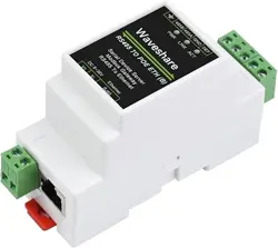

RS485 TO POE ETH (B)
PoE Ethernet port + Electrical
isolation
RS485 to Ethernet serial server
RS485 TO ETH (B)
Common Ethernet port
RS485 TO POE ETH (B)
Overview
There are two versions of this product, the two are the
same in software functions, and the differences in
hardware are as follows:
RS485 TO ETH (B): Common Ethernet connector,
9~24V wide voltage power supply via terminal
block.
RS485 TO POE ETH (B): Hardware upgrade version,
can support PoE network port power supply, can
also support 6~36V wide voltage via terminal block,
with electrical isolation.
Introduction
This is an RS485 device data collector/IoT gateway specially designed for the industrial
environment, which combines serial server, Modbus gateway, MQTT gateway, RS485 to
JSON, and other functions. It has an RS485 interface and an Ethernet interface. It adopts
the rail-type installation, which is compact and easy to install. It is very suitable for the
collection of various RS485 instruments and sensors in the industrial field, including the
collection of the local network or the autonomous collection of uploading to the cloud
server.
Parameters
Model RS485 TO ETH (B) RS485 TO POE ETH (B)
Product Types Serial server, Modbus gateway, MQTT gateway
Basic Functions Realize RS485 to Ethernet bidirectional transparent transmission
Communication
Interface
RS485 × 1, Network Port × 1
Power Supply Screw Terminal DC 9~24V Screw terminal DC 6~36V or PoE port
Isolation Protection No Isolation Power isolation, signal isolation protection
Communication Port
Ethernet
Normal Network Port PoE port, support IEEE 802.3af standard
10 / 100M self-adaptive RJ45 port, 2 KV grade anti-surge protection
Serial Port RS485 Isolated RS485
UART Parameter
Baud Rate 300 ~ 115200 bps
Parity Bit None, odd parity, even parity, mark, space
Data Bit 5 ~ 9 bit
Flow Control No Flow Control
Software
Protocol Ethernet, IP, TCP, UDP, HTTP, ARP, ICMP, DHCP, DNS
Config Way
Host computer configuration, WEB browser, device management
function library
Communication Way TCP/IP direct communication, virtual serial port mode
Working Mode
TCP server, TCP client (the TCP server also coexists), UDP, UDP
multicast
Others
Operating
Temperature
-40
℃
~ 85
℃
Humidity Range 5% ~ 95% relative humidity
Dimensions L × W × H: 87 × 36 × 59 mm
Hardware Description
Software Features
Support TCP server, TCP client, UDP mode, and UDP multicast. When acting as a TCP
client, it also supports TCP server-side functions. Supports 30 TCP connections as a TCP
server and 7 destination IPs as a TCP client.
The baud rate supports 1200~115200bps, the data bit supports 5~9 bits, and the check
digit can be no check, odd check, even check, mark, or space.
Support the function of sending MAC address when the device is connected, which is
convenient for cloud management of the device.
Provides a secondary development kit DLL development library for searching and
configuring devices on the computer side.
Support Web browser configuration, support DHCP to obtain IP dynamically, and DNS
protocol to connect domain name server address.
Support cloud remote search for devices, the configuration of device parameters, and
device program upgrades.
Support remote viewing of the device's TCP connection status, and serial port data
sending and receiving status through software. The virtual serial port supports the data
monitoring function.
Advanced Software Function
Support Modbus gateway function, support Modbus RTU to Modbus TCP. It can support
storage-type Modbus, and can automatically collect device data and store it; it also
supports a non-storage mode Modbus gateway.
Support multi-host function: In the query mode of one question and one answer, the
support network port allows multiple computers to access the same serial device at the
same time.
Support MQTT gateway function.
Support JSON to Modbus RTU and 645-meter protocol, support HTTP POST, and HTTP
GET format to upload data.
Support NTP protocol to obtain network time, which is used for serial output, and the
latter is used for protocol content upload.
Support custom heartbeat package and registration package function: It is convenient to
communicate with the cloud and identify devices.
It supports the function that password authentication is required to establish a
connection through TCP to ensure connection security.
It supports the function of data submission and delivery in HTTP mode, and the cloud
can directly use the HTTP GET command to interact with the serial port data of the
device.
Application
As an IoT gateway as a communication bridge between devices and the cloud.
Power, Smart Meter, and Energy Monitoring.
Remote monitoring and program download of various automation PLCs.
Various configuration software and equipment communication interfaces.
Access control security field equipment networking.
Quick Test
Hardware Connection
Here RS485 TO ETH (B) is taken as an example, and RS485 TO POE ETH (B) is
connected in the same way.
Generally speaking, the serial server only needs to connect the power supply, serial port,
and network cable. Among them, the power supply can use the field 2-wire power supply,
which can be directly connected to the positive and negative terminals of the power supply.
The serial port needs to be connected according to the user's serial port device. Connect
485 positive to 485A and 485 negative to 485B. The Ethernet port is connected to a
common network cable, which can be directly connected to the computer or connected to
the network through a switch.
Software Installation
Vircom can be used to configure parameters such as device IP and create virtual serial
ports. If you don't need the virtual serial port function, you can just download the free
version configuration software.
VirCom
Virtual serial port driver
The driver installation needs to be decompressed. Double-click the software to install. If
the virtual serial port in Vircom is not displayed, restart it and check it again.
Examples
TCP Communication Test
Software Preparation
VirCom
Sscom5.13.1
Operating Steps
After Vircom is installed and the device hardware connection is finished, the software is run
as shown in the figure, and then you can click "Device Management" as shown in the
figure. With Vircom, it is very convenient to search and configure device parameters in
different network segments, as long as the device and the computer running Vircom are
under the same switch. The following tests also require a
USB TO RS485 device .
The serial port to the Ethernet port and the Ethernet port to the serial port data
transparent forwarding function of the serial port server. Assuming that the COM port (USB
TO RS485) of the PC is now connected to the serial port of the serial port server, then open
the serial port debugging assistant window and open the corresponding COM port, as
shown below:
In addition, open another serial port debugging assistant window and use it as a TCP client
mode, fill in the destination IP as the IP of the serial port server (currently 192.168.1.200),
the destination port as 4196, and then click the "Open" button, as shown in the figure
below:
In the serial debugging assistant SSCOM2 set as TCPClient, enter "TCPClient: Waveshare
Test" and click send, then the data will be transferred to the RS485 interface through the
serial server's network port, and then sent to the USB TO RS485, and then displayed in the
serial debugging assistant SSCOM1 out; conversely, enter "USB TO RS485: Waveshare
Test" in SSCOM1, click send, you can also send to SSCOM2, and display it.
Virtual Serial Port Test
The SSCOM2 in the figure communicates directly with the serial port server through TCP. In
order to allow the user's already developed serial port software to communicate with the
serial port server, a virtual serial port needs to be added between the user program and the
serial port server. As shown in the figure, Vircom, and user programs run on one computer,
Vircom virtualizes a COM port and makes this COM port correspond to the serial port
server. When the user program opens COM communication, it can be sent to the user's
serial device through the Vircom serial server. The steps to do this are shown below:
Click the "UART management" in the Vircom interface, click "add", and then choose COM2.
Among them, COM5 is the COM port that did not exist in the computer.
Then enter the device management, and double-click the device that needs to be bound to
COM2. As shown in the figure, select COM2 in the "Virtual Serial Port" list in the upper left
corner. Then click "Modi fy Settings", click "Restart Device", and return to the main interface
of Vircom. It can be seen that COM2 has been connected to the device whose IP is
192.168.1.200. In this case, COM2 can be used instead of SSCOM2 for communication.
Open SSCOM to simulate the user's serial port program, open COM2 (the virtual serial port
above), open another SSCOM to simulate a serial port device, and open COM3 (hardware
serial port). At this time, the data link sent by COM2 is as follows: COM2 -> Vircom -> the
Ethernet port of the serial server -> the serial port of the serial server -> COM3.
Conversely, COM3 to COM2 can also transmit data: COM3 -> the serial port of the serial
server -> the Ethernet port of the serial server -> Vircom -> COM2. As shown in the figure
below, both parties send and receive data. If COM4 is replaced with the user serial device,
then COM5 can realize the communication with the user device.
MODBUS TCP Test
By default, the data between the serial port and the Ethernet port is transparently
transmitted. If you need to convert Modbus TCP to RTU, you need to select the conversion
protocol as "Modbus TCP <--> RTU" in the device settings dialog box, as shown in the
figure below. At this time, the device port automatically changes to 502. At this time, the
user's Modbus TCP tool is connected to the IP port 502 of the serial server and the sent
Modbus TCP command will be converted into an RTU command and output from the serial
port. For example, if the serial port server network port receives the Modbus TCP command
of 00 00 00 00 00 0601 03 00 00 0a, the serial port outputs the command of 01 03 00 00
00 0a c5 cd. Note: The serial port may send multiple 01 03 00 00 00 0a c5 cd commands
because the default Modbus adopts the storage mode, which will automatically train the
query commands. How to switch to non-storage mode will be explained later.
If the user's Modbus TCP software is used as a slave station (Slave), it is necessary to
select the conversion protocol, then change the working mode to the client, the destination
IP to the IP of the computer where the Modbus TCP software is located, and the
destination port to 502, as shown in the figure below.
WEB Configuration
Using Vircom, you can search and configure device parameters in different network
segments. For Web configuration, you must first ensure that the computer and the serial
server are in the same IP segment, and you need to know the IP address of the serial
server in advance. But web configuration can be done on any computer without Vircom.
1. Enter the IP address of the serial server in the browser, such as
http://192.168.1.200 .
2. Enter a password in Password: There is no login password set by default in the factory,
you can enter a password at will, and click the Login button to log in. After setting the
password to log in, the settings at "Modify webpage login password" will take effect:
3. The serial server parameters can be modified on the web page that appears. For the
relevant parameters, please refer to Table 4 for the meaning of the parameters.
4. After modifying the parameters, click the "Submit Modification" button.
5. If configuring and downloading MQTT and Jetson Modbus firmware overwrites the
webpage file of the configuration interface, resulting in the failure to open the configuration
webpage, please follow the steps below to re-download the webpage file:
Configure web file to RS485 TO ETH (B):
Resource
Documentation
User Manual
Software
Vircom
virtual serial port control
SSCOM
TCPIP/UDP debug tool
Modbus Slave
Certificate
CE EMC
Related Application
RS485 TO ETH (B) Connect Alibaba Cloud And EMQX
FAQ
Question:RS485 TO ETH (B)LINK is yellow, what should I do if I cannot access
the network?
Answer:
Set static IP, for example:
RS485 TO ETH (B) set to 192.168.1.200 port number 1111.
The computer is set to 192.168.1.199 port number 1111.
Tested with the TCP server shared by the Internet community: 120.79.100.197 port
number 10002.
If it still doesn't work, please reset to factory settings.
Question:RS485 TO ETH (B) How to restore factory settings?
Answer:
1) Short the NC pin for 5 seconds:
2) Get the default parameters and modify the settings:
Question:What is the power of RS485 TO ETH (B)?
Answer:
The detailed data is as follows:
Question:What should I do if the web configuration interface cannot be
opened?
Answer:
Configuration and download other firmware such as MQTT and Jetson Modbus cover the
configuration interface web page file, you need to re-download
2043_waveshare_web_zx.zip configuration interface web file to RS485 TO ETH (B):
Support
If you require technical support, please go to the page and open a ticket.
0:00
Overview
Introduction
Parameters
Hardware Description
Software Features
Advanced Software Function
Application
Quick Test
Hardware Connection
Software Installation
Examples
TCP Communication Test
Software Preparation
Operating Steps
Virtual Serial Port Test
MODBUS TCP Test
WEB Configuration
Resource
Documentation
Software
Certificate