
Instructions for use
PAC AP Inverter Series

2
AP
Contents
DESCRIPTION ............................................................................................................3
INSTALLATION ........................................................................................................... 5
Electrical Connection ..............................................................................................5
What is the inverter technology .............................................................................5
Air conditioning without installation ......................................................................6
Sliding windows .....................................................................................................7
Air conditioning with installation ...........................................................................7
USE ........ .................................................................................................................. 8
Operating from the control panel ...........................................................................8
Description of the control panel..............................................................................8
Control panel operation ..........................................................................................9
Mode selection .......................................................................................................9
Select the temperature scale ................................................................................10
Operating from the remote control .......................................................................11
Using the remote control ......................................................................................11
Description of the remote control .........................................................................11
Turning the appliance ON/OFF ..............................................................................12
Selecting the operating modes .............................................................................12
Selecting the temperature ....................................................................................12
Selecting the air ow ...........................................................................................12
Setting the timer ..................................................................................................12
Eco Real Feel function ........................................................................................... 13
Silent function .....................................................................................................14
Swing function .....................................................................................................14
SELF-DIAGNOSIS ...................................................................................................... 15
TIPS FOR CORRECT USE ............................................................................................ 17
Cleaning ...............................................................................................................17
Cleaning the cabinet ............................................................................................17
Cleaning air lter ..................................................................................................17
Start of season checks ..........................................................................................18
End of season operations ......................................................................................18
Technical specications ........................................................................................18
Limit conditions....................................................................................................18
TROUBLESHOOTING ................................................................................................. 19
3
AP
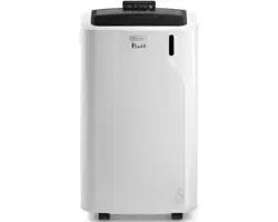
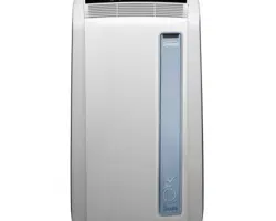
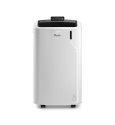
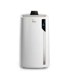
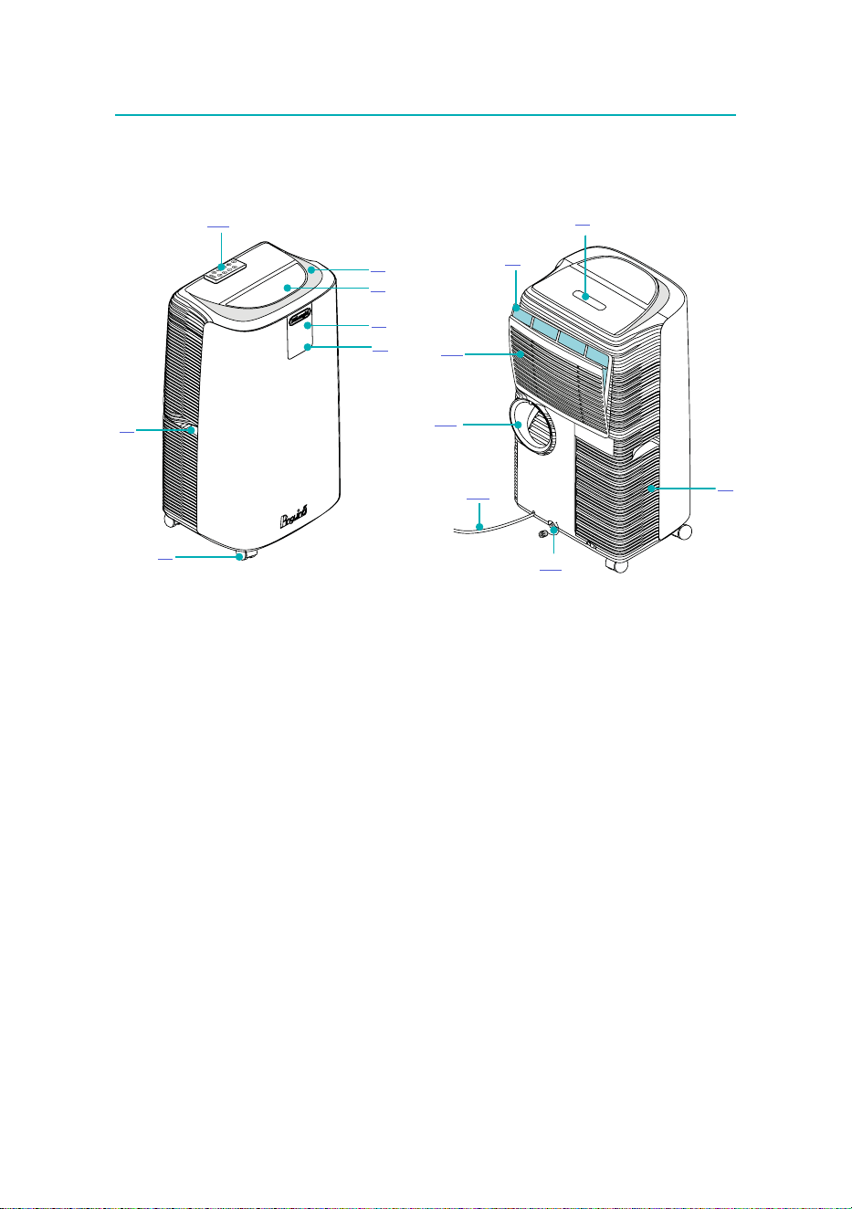
Description
A1. Air outlet
A2. Air outlet ap
A3. Remote control signal receiver
A4. Control panel
A5. Castors
A6. Handles
A7. Filter
A8. Remote control compartment
A9. Air intake grille
A10. Drainage hose with cap
A11. Power cable
A12. Air exhaust hose housing
A13. Air intake grille
A14. Remote control
A12
A3
A4
A1
A13
A11
A2
A5
A6
A7
A9
A10
A14
A8
4
B1
B5
B9
B8
B4
B2
B3
B7
B6
B10
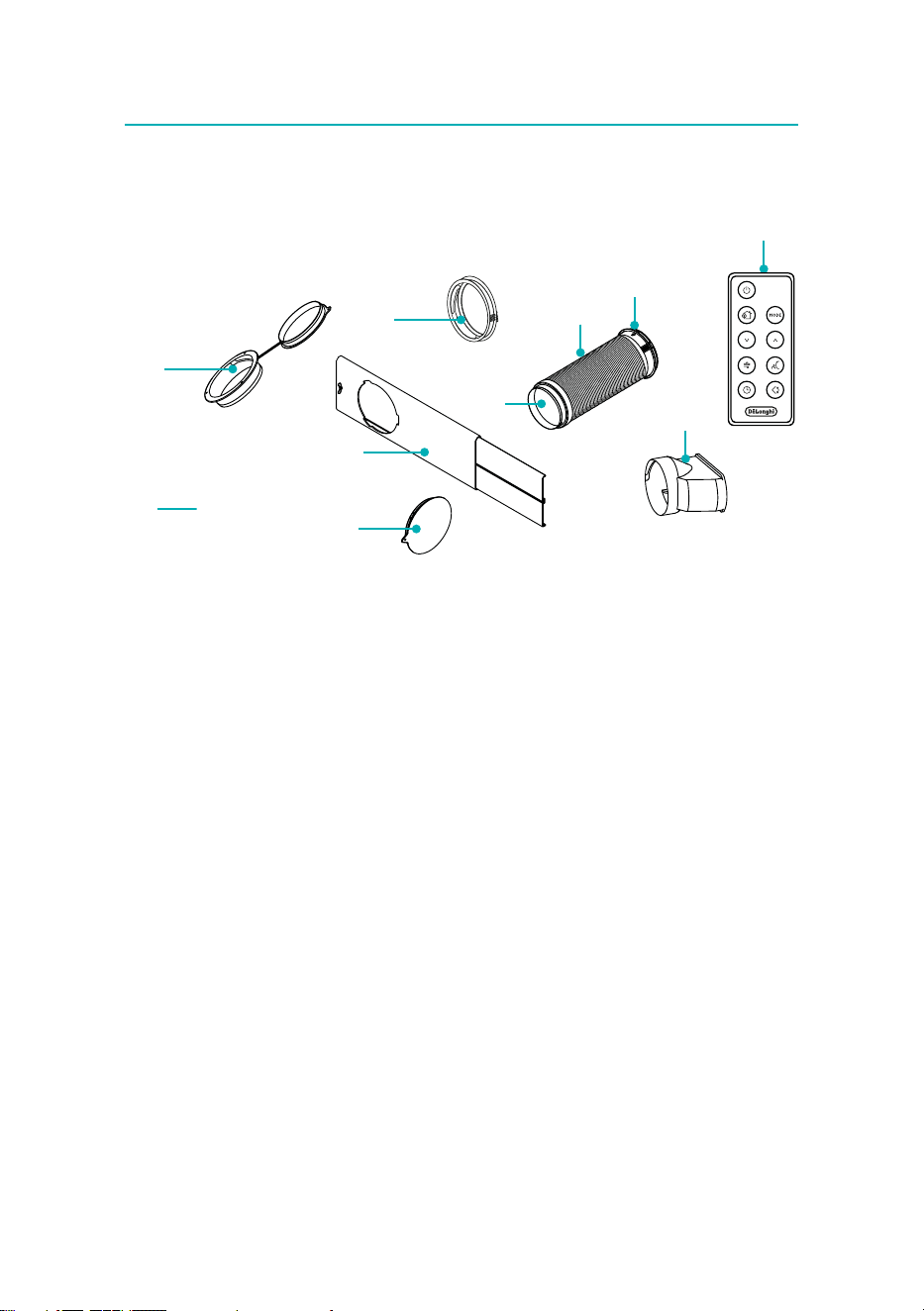
B1. Wall ange with cap
B2. Air exhaust hose
B3. Hose adapter
B4. Adapter for window bracket
B5. Window bracket with wing nut
B6. Adapter for wall mounting/window outlet
B7. Window outlet
B8. Remote control
B9. Window bracket cap
B10. Screws

5
AP
Installation
Electrical Connection
Before plugging into the mains, check the following:
• the mains voltage is the same as that indicated on the plate on the
back of the appliance;
• the socket and electrical line are sized to support the load required;
• the socket is the proper type for the plug, otherwise, replace the
socket;
• the socket is connected to an ecient earthing system.
The manufacturer is not responsible in the event of noncompliance
with these injury prevention standards.
The power cable must only be replaced by specialised techni-
cians.
Please note: The instructions below will enable you to prepare your air
conditioner for operation as eciently as possible. Before use, make sure
the air intake and outlet grilles are unobstructed.
Please note: This appliance is provided with an auto-evaporation feature
for condensate removal during cooling and dehumidifying modes.
What is the inverter technology
The Inverter technology has been designed to oer the best comfort with
optimised energy consumption. It guarantees very high cooling power
to rapidly reach the set temperature, which is then maintained constant
over time. This technology is essentially based on an electronic device
that allows frequency variations of the electric motor, to adjust the ro-
tation speed of the compressor and obtain a modulation of the cooling
power.
This device eliminates the sequence of On–O required by conventional
air conditioners to keep a xed room temperature, with consequential
high temperature uctuations around the set temperature and longer
time gaps before it is reached.
The Pinguino Inverter always operates at the optimum cooling capacity
and the maximum energy eciency as the power consumption is limited
to eective requirements, both in periods of average and low thermal
load (morning or evening), and during the hotter and more humid times
(middle of the day), when the Inverter technology is especially valuable.
6
Air conditioning without installation
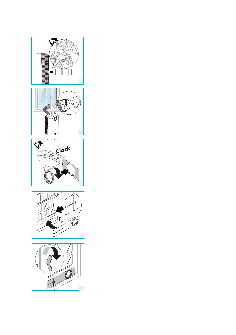
Casement window
If you have a casement window proceed as follows:
• Fit the air exhaust hose (B2) in the relevant housing located on the
rear side of the appliance paying attention to align the two arrows
as shown in gure 1, in order to hook it. To remove the exhaust hose
rotate it in the clockwise or anticlockwise directions.
• Screw the window outlet (B7) and place outside the window to ex-
haust the hot air (g. 2).
double-hung window
If you have a double-hung window proceed as follows:
• Insert and lock the adapter for window bracket (B4) into the slot of
the window bracket (B5) (g.3)
• Place the window bracket in the window sill, and extend the bracket
fully within the window frame (g. 4).
• Fix the bracket by the wing nut (g. 5) (Should the window bracket
be too large for the window the plastic can be cut with a saw by a
qualied professional).
• Insert the air exhaust hose (B2) into the adapter for window bracket
(B4) and rotate it as shown in g. 6.
• In order to facilitate the tting of the air exhaust hose (B2) in the
relevant housing located on the rear side of the appliance, position
the hose adapter ‘s tabs (B6) in a vertical axis and proceed as shown
in g.1.
2
1
Clack
3
4
5
7
Sliding windows
Thanks to the locking wing nut, it’s possible to use the window bracket
also for sliding windows. Position the bracket vertically with the hole in
the lower part so to allow a easier installation of the exhaust hose.
Air conditioning with installation
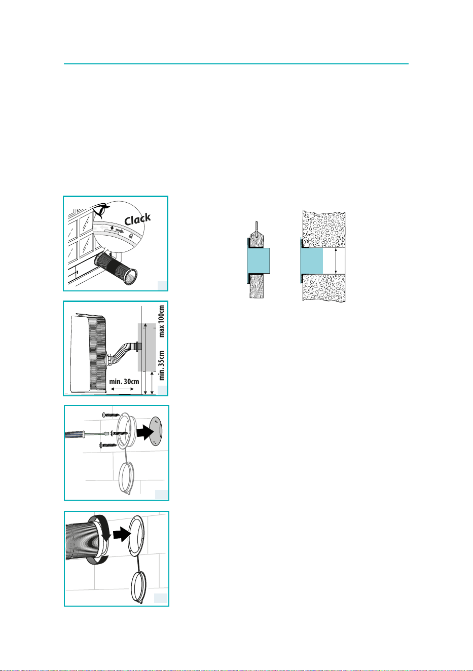
• Fit the air exhaust hose (B2) in the relevant housing located on the
rear side of the appliance (g. 1).
• Drill a hole 150 mm in an outside wall. Respect the distances, di-
mensions and height of the hole given in gure 7.
ø 150 mm
in the wooden kick-
board of a French
window
in the wall: you are
recommended to
insulate the section
of wall using suita-
ble insulation.
• Insert the wall ange (B1) into the hole and secure it with the sup-
plied screws (B10) (Fig. 8a). (The screwdriver is not supplied.)
• Insert and screw the exhaust pipe (B2) into the wall ange (B1) (Fig.
8b).
• When the hose (B2) is not connected, the drilled hole can be closed
with the ange cap (B1).
Please note: As special tools are required for installation, we suggest you
have the appliance installed by specialized personnel.
•
When installing the air conditioner, you should leave a door slightly
open little as 1 cm to guarantee correct ventilation and room pressure.
• Keep the air hose as short and free of curves as possible to avoid
constrictions.
Clack
max 100cmmin. 35cm
min. 30cm
6
7
8a
8b
8
AP
Operating from the control panel
C1
C13
C11
C16
C9
C8
C7
C6
C14
C15
C3
C4
C2
C5
C10
C12
C17
Description of the control panel
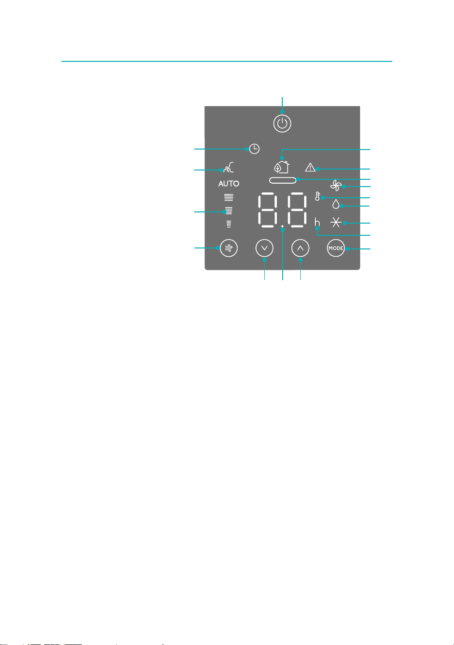
C1. ON/STAND-BY (on/o) key
C2. MODE key
C3. Temperature increase key
C4. Temperature decrease key
C5. Fan symbol
C6. Air conditioning symbol
C7. Dehumidifying symbol
C8. Eco Real Feel symbol
C9. Fan speed key
C10. Silent symbol
C11. General alarm symbol
C12. Set temperature values, programmed on/o time
C13. Timer symbol
C14. Timer hours indicator
C15. Temperature indicator
C16. Eco Real Feel status indicator
C17. Selected fan speed indicator
Use
9
Control panel operation
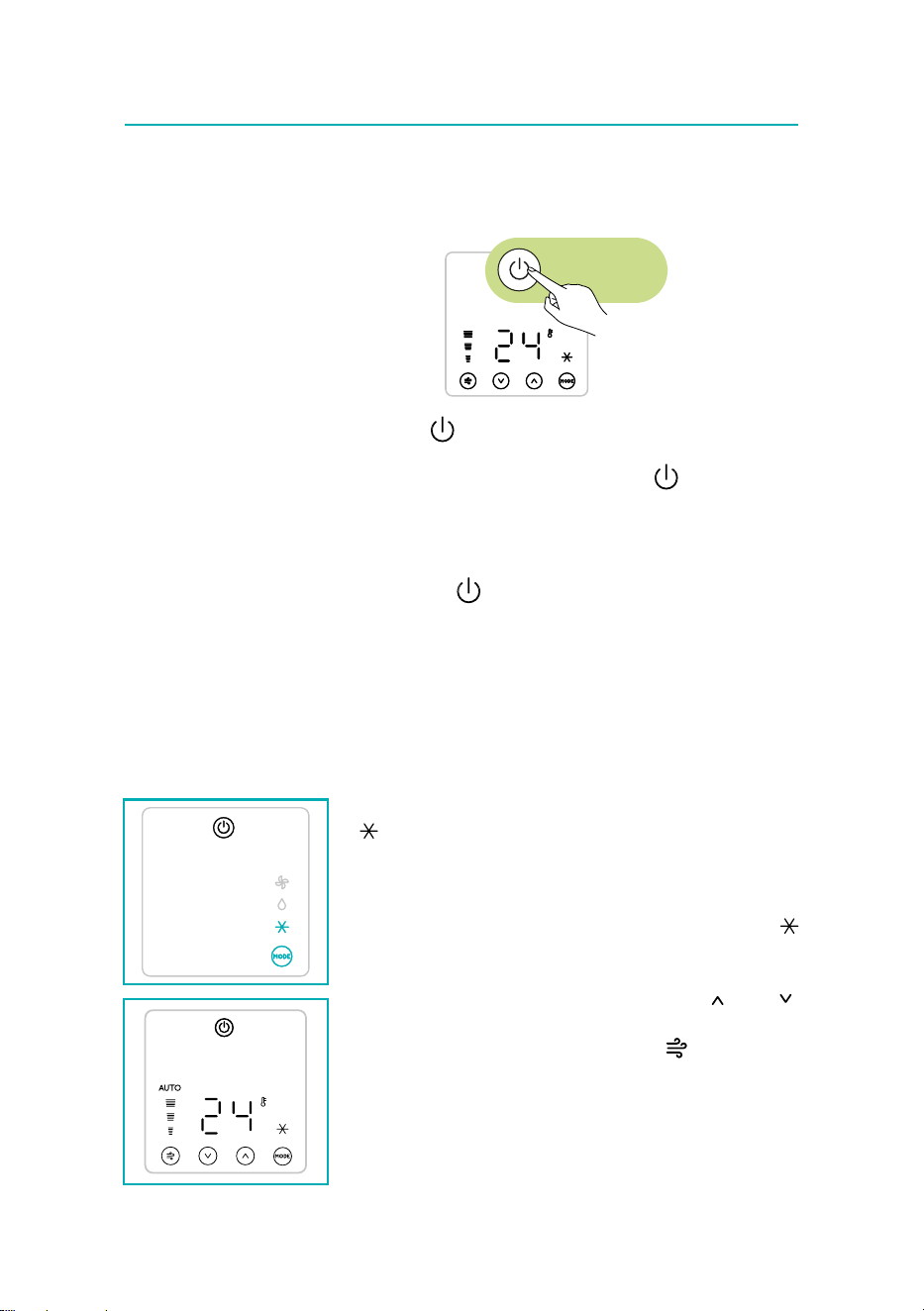
Turning the appliance on and o
Insert the plug in the socket. Two dashes appear on the display indicating
that the appliance is in stand-by.
I/0
Touch the (C1) key to turn on the appliance.
When the appliance comes on the last function set before it was shut o
is activated. To turn the appliance o, touch the key.
Please note: If start-up is not continued, after a few minutes the display
light dims in order to reduce energy consumption.
Please note: Never turn o the air conditioner by simply pulling the
plug. Touch the
key in order to put your air conditioner in stand-by
and wait a few minutes before pulling the plug. In this way, the appli-
ance can perform the operating status checks.
Please note: During operation it is normal for the appliance to have fan
speed uctuation.
Mode selection
To select the desired operating mode, touch repeatedly the MODE key
(C2) until the desired function is selected.
Air Conditioning mode
This is ideal for hot and humid weather when the room needs to be both
cooled and dehumidied.
To correctly set this mode:
• Touch repeatedly the MODE key (C2) until the air conditioning
symbol appears. Wait a few seconds for the command to be ac-
quired. The display will show the desired temperature.
• To change the temperature to be reached, touch the
(C3) or
(C4) key.
• Select the desired fan speed by touching the
(C9) key.
The air ows available are:
Minimum air ow: when maximum silent operation is desired.
Medium air ow: when the noise level needs to be low but with a good
comfort level.
10
Maximum air ow: to reach the desired temperature as soon as pos-
sible.
Auto: The appliance automatically chooses the best fan speed based on
the temperature selected and the environmental conditions.
The most suitable temperatures during the summer range from 24 to 27°C.
However, setting the temperature signicantly lower than the outdoor tem-
perature is not recommended.
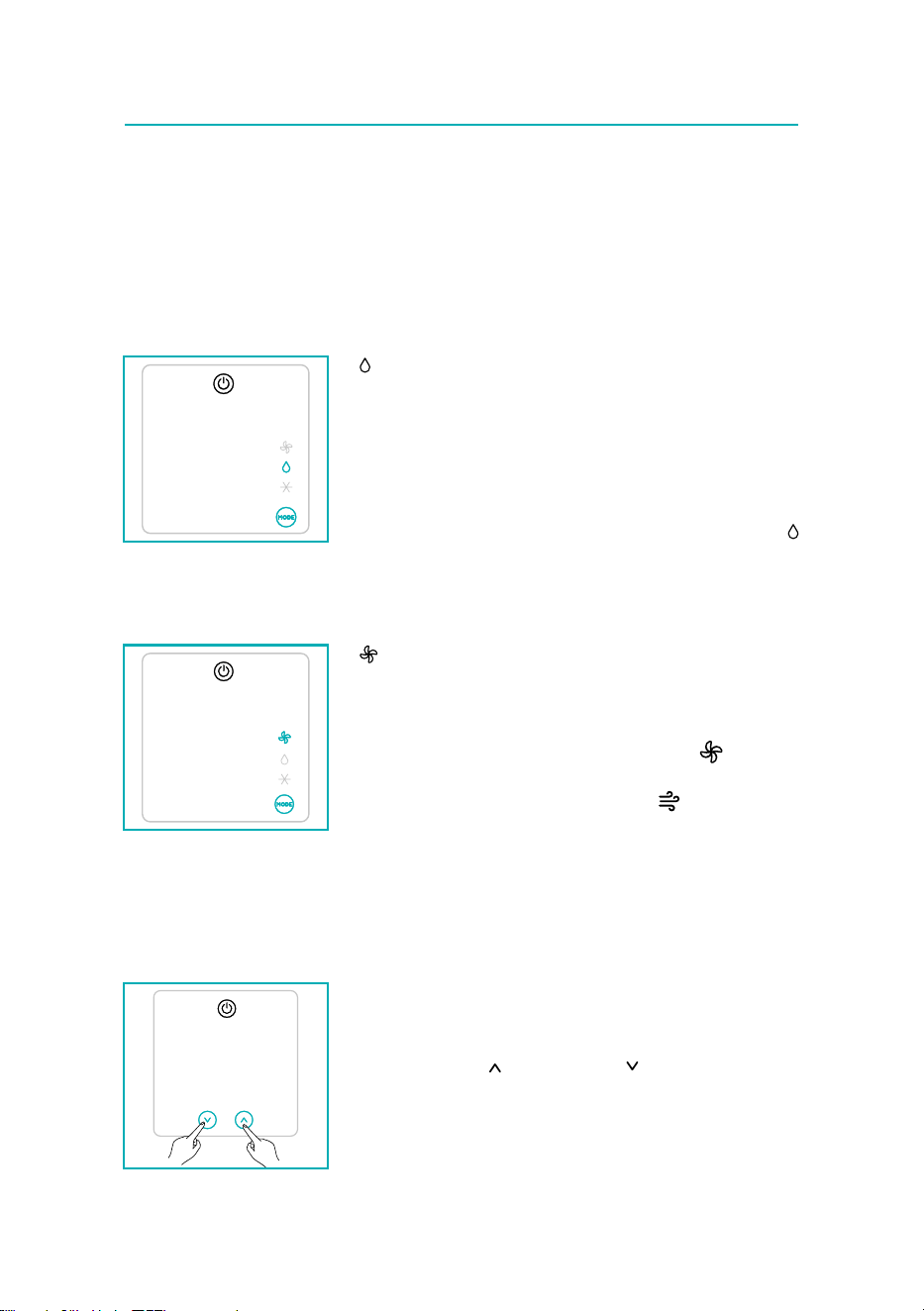
Dehumidifying mode
This is ideal for reducing humidity in the room (spring and autumn, damp
rooms, rainy periods, etc). For this type of use, the appliance must be set
up as for air conditioning mode. That is, the air exhaust hose (B2) must
be tted to the appliance to allow the humidity to be discharged outside.
To correctly set this mode:
• Touch repeatedly the MODE key (C2) until the dehumidifying
symbol appears. Wait a few seconds for the command to be ac-
quired.
• The appliance will automatically choose the best air ow.
Fan mode
When using this mode, the air exhaust hose (B2) does not need to be
attached to the appliance.
To correctly set this mode:
• Touch repeatedly the MODE (C2) key until the fan symbol ap-
pears. Wait a few seconds for the command to be acquired.
• Select the desired fan speed by touching the (C9) key.
The air ows available are:
Minimum air ow: when most silent operation is desired.
Medium air ow: when the noise level needs to be low but with a good
comfort level.
Maximum air ow: for maximum performance.
Select the temperature scale
The temperature can be displayed in °C or °F.
To change the temperature unit of measure touch simultaneously for ten
seconds the increase (C3) and decrease (C4) keys.
11
Operating from the remote control
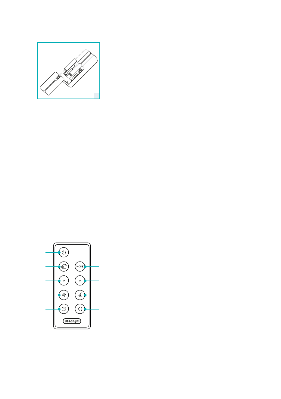
Inserting or replacing the batteries
• Remove the cover on the rear of the remote control;
• Insert or replace the batteries with two new LR03 “AAA” 1.5V bat-
teries, inserting them correctly (see the directions inside the battery
compartment) (g. 9);
• Replace the cover.
Please note: If the remote control unit is replaced or discarded, the
batteries must be removed and disposed of in accordance with current
legislation as they are harmful to the environment. Do not mix old and
new batteries.
Do not mix alkaline, standard (carbon-zinc) or rechargeable (nickel-cad-
mium) batteries. Do not dispose of batteries in re. Batteries may explode
or leak. If the remote control is not be used for a certain length of time,
remove the batteries.
Using the remote control
• Point the remote control at the receiver (A11) on the air conditioner.
The remote control must be no more than 7 metres away from the
appliance (without obstacles between the remote control and the
receiver).
• The remote control must be handled with care. Do not drop it or
expose it to direct sunlight or sources of heat.
Please note: The remote control can be safely stored in the appropriate
compartment (A12).
Description of the remote control
D1.
ON/STAND-BY button
D2. MODE button
D3. Increase button
D4. Decrease button
D5. Air ow button
D6. Swing button
D7. Silent button
D8. Timer button
D9. Eco Real Feel button
D1
D9
D4
D5
D8
D2
D3
D7
D6
9

12
Turning the appliance ON/OFF
• Plug into the outlet.
• Press the
C1C2
C4
C11
C13
C12
C9
C7
C5
C6
C3
C16
C14
C10
C15
C17
C8
button (D1), when turned on, the air conditioner starts
operating in the same mode as when it was turned o.
• To switch the appliance o, press the
C1C2
C4
C11
C13
C12
C9
C7
C5
C6
C3
C16
C14
C10
C15
C17
C8
button (D1).
Please note: Never switch the appliance o by removing the plug.
Always switch it o by pushing the
C1C2
C4
C11
C13
C12
C9
C7
C5
C6
C3
C16
C14
C10
C15
C17
C8
button and waiting few minutes
before removing the plug. Only in this way the appliance will perform the
standard checkings.
Selecting the operating modes
To select the desired operating mode, press repeatedly the MODE button
(D2) until the desired function is selected.
Most of the commands available on the remote control correspond to
those on the appliance control panel.
Selecting the temperature
In conditioning mode press (D3) and (D4) buttons to increase/de-
crease the desired temperature.
Selecting the air flow
In conditioning and fan modes, press (D5) button to select the de-
sired air ow.
Setting the timer
The timer allows the delayed start up or shut down of the appliance. This
function will prevent wasting electricity by optimising the operating pe-
riods.
How to program delayed shut down
• While the appliance is on in any operating mode, delayed shut down
can be programmed.
• Press the
C1C2
C4
C11
C13
C12
C9
C7
C5
C6
C3
C16
C14
C10
C15
C17
C8
timer button (D8), the timer symbol (C13) and hours
(C14) light up.
• Press the (D3) and (D4) buttons until the desired number of
hours to shut down appears on the display.
A few seconds after the timer is set, the setting is acquired, the display
shows the operating mode and the timer symbol stays lit.
Once the set time is elapsed, the air conditioner goes into standby. To can-
cel the timer program, press the
C1C2
C4
C11
C13
C12
C9
C7
C5
C6
C3
C16
C14
C10
C15
C17
C8
timer button (D8) twice. The timer
symbol (C13) will go o.
Please note: Once the timer has been activated, by pressing the timer
button only one time, the remaining hours to shut down will be dis-
played.
13
How to program delayed start up
• Plug in the appliance and set to standby.
• Press the
C1C2
C4
C11
C13
C12
C9
C7
C5
C6
C3
C16
C14
C10
C15
C17
C8
timer button (D8), the timer symbol (C13) and hours
(C14) light up.
• Press the (D3) and (D4) buttons until the desired number of
hours to start up appears. Start up can be programmed at any time
within the 24 hours that follow.
A few seconds after the timer is set, the setting is acquired, the display
shows the standby mode and the timer symbol stays lit.
When the set time is elapsed, the appliance will start to operate in the
same operating mode that was previously set.
To cancel the timer program, press the timer button (D8) twice.
The timer symbol (C13) will go o.
Please note: Once the timer has been activated, by pressing the timer
key only one time, the remaining hours to the start up will be displayed.
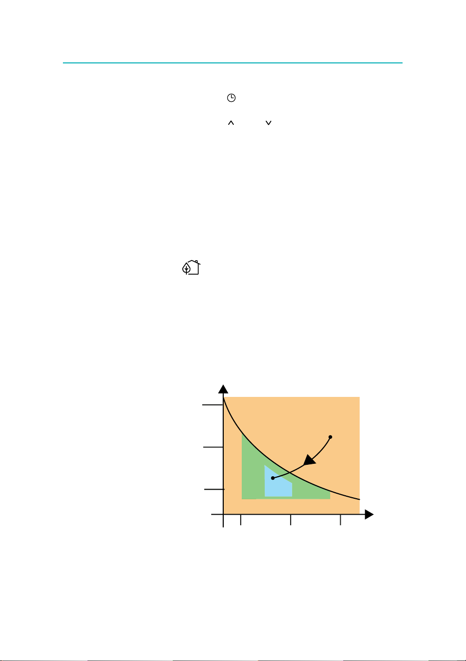
Eco Real Feel function
Eco Real Feel is the innovative De’Longhi technology that works
simultaneously on temperature reduction and humidity control, securing
best comfort level. With traditional systems, during working time,
optimal comfort conditions may be reached but not secured over time.
With Eco Real Feel, once optimal comfort is reached, PAC automatically
modulates compressor action and air ow, to keep it over time.
To activate the function, press the Eco Real Feel button (D9). The Eco Real
Feel symbol (C8) appears.
HUMIDITY
TEMPERATURE
HIGH
MEDIUM
LOW
HIGH
MEDIUM
LOW
Operating curve
After approx. 1 minute, the ECO REAL FEEL indicator (C16) turns on. It
changes color when approaching the best comfort level (see graph be-
low).

14
ORANGE LIGHT: Room conditions far from
optimal level.
GREEN LIGHT: Most people feel good room
conditions, near optimal level.
BLUE LIGHT: Best comfort level.
• The well-being feeling is a subjective condition. For this reason, dif-
ferent people may judge dierently the same environmental condi-
tions.
• In particularly severe environmental conditions (large size of the en-
vironment, high temperature or humidity outside, poor insulation
of the room, too many of people or strong heat load in the room,
strong exposure to the sun ...) this device may not be able to reach
the best comfort level.
Silent function
By activating this function (available in conditioning mode only) the op-
erating noise is further reduced. To activate it, press silent button (D7) on
the remote control. The display shows the relative symbol (C10).
Swing function
The swing button (D6) activates and deactivates the swing function. When
the internal fan is running, the swing function distributes the air evenly
into the room moving the ap forwards and backwards alternatively. If
pressed again, the ap will be locked into its current position.
NOTE: If the fan is not running, the swing function will also not operate.
In order to avoid damaging the internal mechanisms, the ap must not be
moved manually.
15
AP
Self-diagnosis
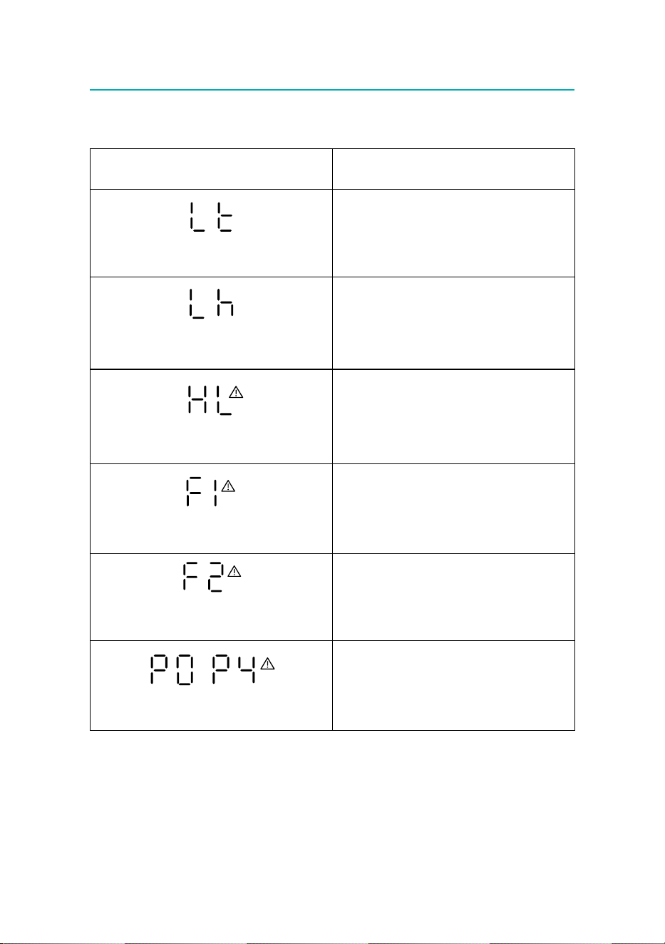
The appliance has a self diagnosis system to identify a number of warning/malfunctions. Error messages are
displayed on the appliance display.
IF ...
IS DISPLAYED,
..WHAT SHOULD I DO?
“Low Temperature”
(Frost prevention)
The appliance is tted with a frost protection device
to avoid excessive formation of ice. The appliance
starts up again automatically when the defrosting
process is completed.
“Low humidity”
The message will only be displayed when in Eco Real
feel function, indicating that the room humidity lev
-
el is extremely low. To resume operation, switch the
unit to any other mode other than the Eco Real Feel
function.
“High Level”
(Internal tray full) and general alarm
Empty the internal safety tank following the instruc
-
tions in the section “End of season operations”.
Failure 1
and general alarm
If this appears, consult the nearest authorized ser
-
vice centre.
Failure 2
and general alarm
If this appears, consult the nearest authorized ser
-
vice centre.
-
“Probe Failure”
(Probe damaged) and general alarm
If this appears, consult the nearest authorized ser
-
vice centre.
16
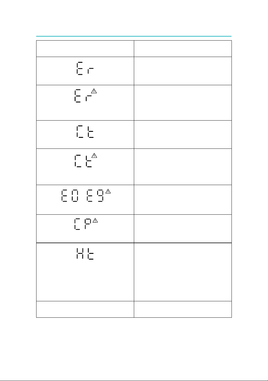
IF ...
IS DISPLAYED,
..WHAT SHOULD I DO?
Anomaly in the appliance performance
When this appears ashing, the appliance is pro
-
viding a checking and is operating some functions
cycles, afterwards this alarm will disappear.
Anomaly in the appliance performance
and general alarm
If this appears steady, consult the nearest authorized
service centre. To reset the alarm, the unit must be
unplugged the re-plugged.
“Compressor temperature” very high
When this appears ashing, the air ow is tempo
-
rarily forced at maximum, then the air ow should
return to the correct values.
“Compressor temperature“ very high
and general alarm
If this appears steady, the protection device has
intervened to avoid excessive temperature of the
compressor. To reset the alarm, the unit must be un
-
plugged then re-plugged.
-
Inverter module error and general alarm
Internal protections have been activated. Try reset
-
ting them before calling the authorized service cen-
tre, by unplugging and plugging it again.
Inverter protect alarm
Internal protections have been activated. Try reset
-
ting them before calling the authorized service cen-
tre, by unplugging and plugging it again.
“Overheating” ashing
The appliance is tted with a safety device to avoid
the compressor’s overheating. Check there are no
obstruction to the air intake/output grille or to the
air exhaust hose. The appliance will operate with the
fans only, utill the temperature decreases to the nor
-
mal conditions, afterwards, the appliance will auto-
matically operate regularly. If the alarm often occurs,
contact your local autho-rised customer services.
Flashing set point The appliance is not operating within the limit con
-
ditions.
17
AP
To ensure optimal results from your air conditioner, follow these recom-
mendations:
• close the windows and doors in the room to be air conditioned.
When using the air conditioner with installation, you should leave a
door slightly open (as little as 1 cm) to guarantee proper ventilation.
• Never use the appliance in very damp rooms (laundries for exam-
ple).
• Protect the room from direct exposure to the sun by partially closing
curtains and/or blinds to make the appliance much more economi-
cal to run.
• Never use the appliance outdoors.
•
Make sure there are no heat sources in the room.
• Make sure the air conditioner is standing on a level surface.
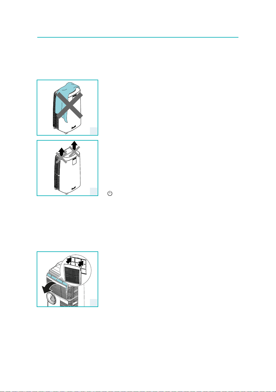
• Do not cover the appliance (g. 10).
• Never rest objects of any kind on the air conditioner.
• Never obstruct the air intake or outlet ap.
• Never lift the appliance from the air outlet conveyor, use the handles
(g. 11).
Cleaning
Before cleaning or maintenance, turn the appliance o by pressing the
C1C2
C4
C11
C13
C12
C9
C7
C5
C6
C3
C16
C14
C10
C15
C17
C8
button, then unplug from the outlet.
Cleaning the cabinet
You should clean the appliance with a slightly damp cloth then dry with a
dry cloth. For safety reasons, never wash the air conditioner with water.
Attention! Never use petrol, alcohol or solvents to clean the appliance.
Never spray insecticide liquids or similar.
Cleaning air filter
The lter helps capture dust and pollen.
If the lter is dirty, air circulation is compromised and the eciency of
the appliance decreases. It is therefore good practice to clean the lter at
regular intervals. The frequency depends on the duration and conditions
of operation. If the unit is used constantly or systematically, you are rec-
ommended to clean the lter once a week.
The lter is housed in the intake grille. To clean the lter, extract as shown
in g. 12. Use a vacuum cleaner to remove the dust collected on the lter.
If it is very dirty, immerse in warm water and rinse a number of times. The
water should never be hotter than 40°C.
After washing the lter, allow it to dry completely before repositioning it.
Tips for correct use
12
10
11
18
Start of season checks
Make sure the power cable and plug are undamaged and the earth sys-
tem is ecient. Follow the installation instructions precisely.
End of season operations
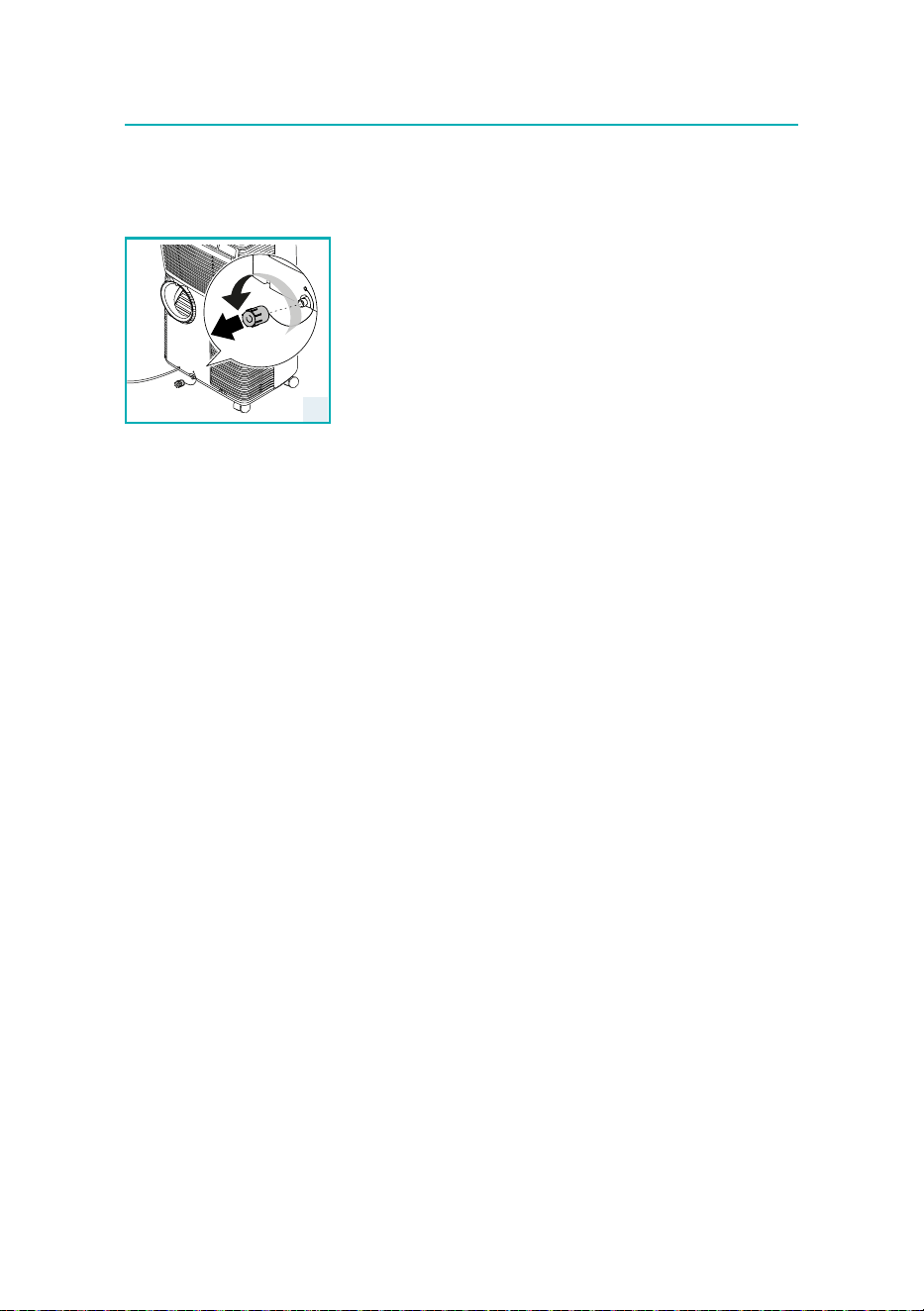
When storing the appliance we suggest you to drain all water from the
circuit: remove the external cap (A10) by unscrewing it in the anticlock-
wise direction (g. 13) and allow the water to drain out into a basin.
When the appliance is empty, replace the caps.
Clean the lter and dry thoroughly before putting back.
Technical specifications
Power supply voltage see rating label
Max. absorbed power
during air conditioning “
Refrigerant “
Cooling capacity “
Limit conditions
Room temperature for air conditioning 18° ÷ 35°C
Transport, lling, cleaning, recovery and disposal of refrigerant
should be performed by a technical service centre appointed by
the manufacturer only.
The appliance should be disposed of by a specialist centre ap-
pointed by the manufacturer only.
Attention!
TO AVOID DAMAGE TO THE UNIT:
NEVER TRANSPORT OR TURN THE APPLIANCE UPSIDE DOWN OR ON ITS
SIDE. IF THIS OCCURS, WAIT 6 HOURS BEFORE TURNING THE APPLIANCE
ON, 24 HOURS IS RECOMMENDED. After the unit has been on its side, oil
needs to return to the compressor to ensure proper function. Without
allowing the unit this time (6-24 hours) the unit may function for only
a short time, and then the compressor will break down from lack of oil.
13
19
AP
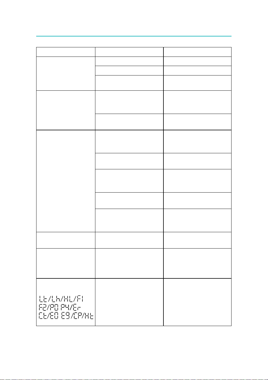
PROBLEM CAUSE SOLUTION
The air conditioner does not
come on
it is not plugged into the outlet plug into the outlet
there is no current wait
the internal safety device has
tripped
call the authorised service centre
The air conditioner works for a
short time only
there are bends or kinks in the air
exhaust hose
position the air hose correctly,
keeping it as short and free of curves
as possible to avoid bottlenecks
something is preventing the air
from being discharged
check and remove any obstacles
obstructing air discharge
The air conditioner works, but
does not cool the room
windows, doors and/or curtains
open
close doors, windows and curtains,
bearing in mind the “Tips for correct
use” given above
there are heat sources in the room
(oven, hairdryer, etc.)
eliminate the heat sources
the air exhaust hose is detached
from the appliance
t the air exhaust hose in the
housing at the back of the appliance
(g. 1).
lter clogged clean or replace the lter as
described above
the technical specication of the
appliance is not adequate for the
room in which it is located.
During operation, there is an
unpleasant smell in the room
lter clogged clean the lter as described above
The air conditioner does
not operate for about three
minutes after restarting it
an internal safety device prevents
the appliance from being restarted
until three minutes have elapsed
since it was last turned o
wait. This delay is part of normal
operation.
One of the following messages
is displayed:
-
-
the appliance has a self diagnosis
system to identify a number of
malfunctions.
see the Self-diagnosis chapter
Troubleshooting

5715117845_00_1225