EN Conversion kit installation instructions
GAS
COOKTOPS
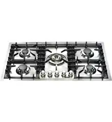
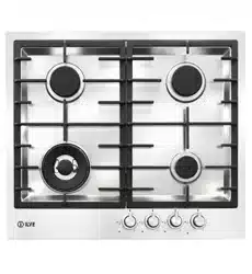
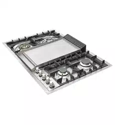
- UHC P (75/95/125/36/48/965/1265)
- UHC PT (75/95/125/36/48/965/1265)
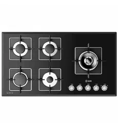
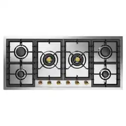
- UHC PM (95/125)
- UHC PMT (95/125)

2

3
WARNING
“This conversion kit shall be installed by a qualied service
agency in accordance with the manufacturer’s instructions
and all applicable codes and requirements of the authority
having jurisdiction. If the information in these instructions
is not followed exactly, a re, explosion or production of
carbon monoxide may result causing property damage,
personal injury or loss of life. The qualied service agency
is responsible for the proper installation of this kit. The
installation is not proper and complete until the operation of
the converted appliance is checked as specied in the
manufacturer’s instructions supplied with the kit.”
CAUTION: The gas supply shall be shut o prior to disconnecting
the electrical power, before proceeding with the conversion.
The kit for the gas conversion of the burners is relevant to the
model of the appliance indicated on the label sti-cking to the
rst page of this booklet. The kit contains the number and
type of orices necessary for the conversion, all the necessary
instructions, a label to stick onto the old one to show the new
setting (see table 2) and the label to be completed by the
technician who performs the conversion. The appliance is pre-
adjusted in factory for the gas indicated on the label put on the
gas inlet pipe. For the conversion to another gas refer to table 3.
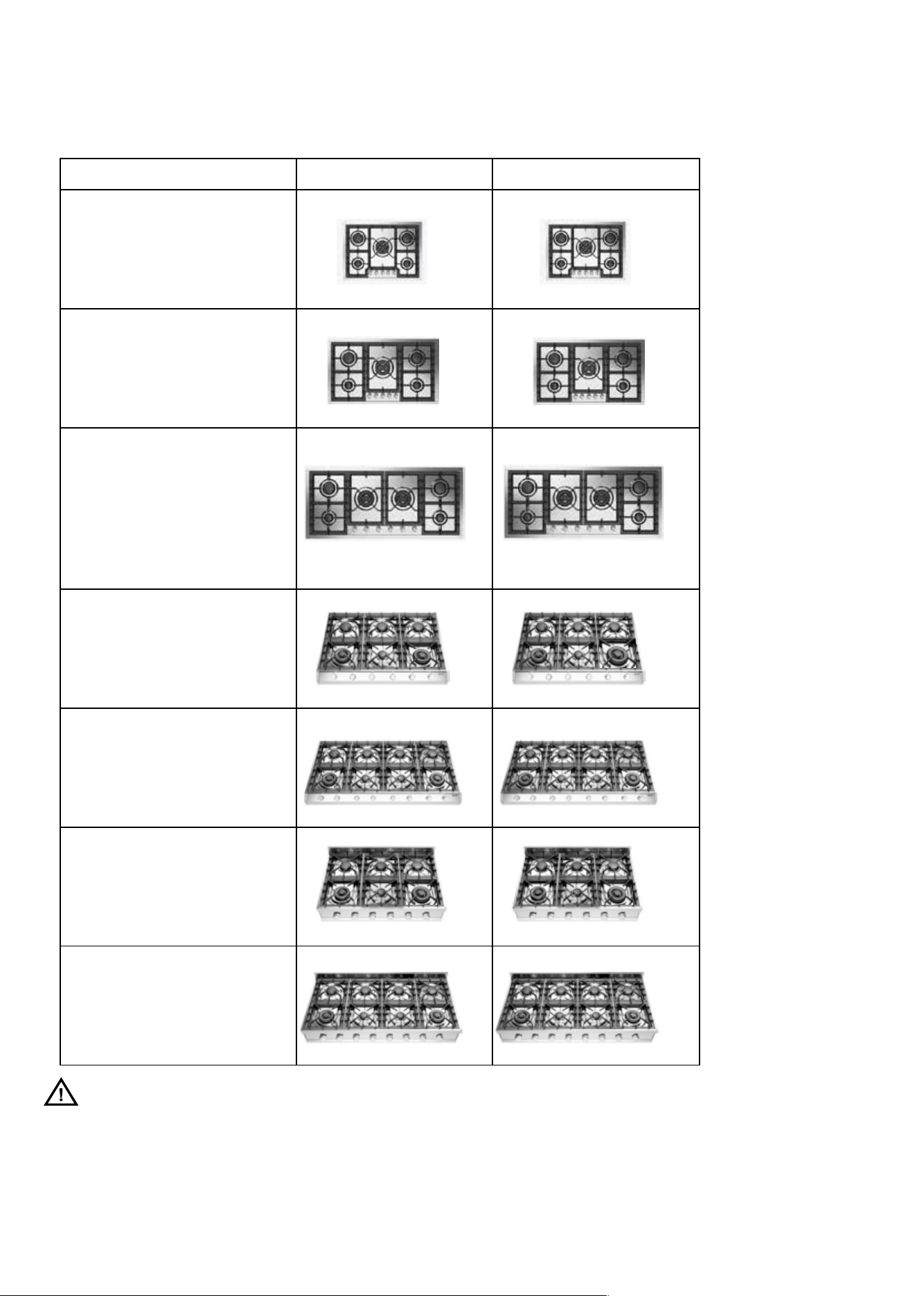
The positions, types of burner and relevant orices for the
models included in this booklet are depicted in table 3. The only
operation to perform aer conversion to a gas dierent from
that shown on the rating plate/label is the adjustment of the
minimum gas ow. (See page 3 of this leaet). Aer conversion
remember to put the new gas indication label (supplied in the
conversion kit) as close as possible to the existing rating plate,
then check the regular ignition of the burners (see pages 3 and
4 of this leaet, “Lighting the burners”).
If the appliance is installed at an altitude exceeding 2,000 ,
a new set of orices can be requested from the supplier or an
authorised service parts distributor.
NOTE: Due to the lower atmospheric pressure at higher
altitudes, foods tend to take longer to cook. Therefore, recipe
adjustments should be made in some cases. In general, no
recipe adjustment is necessary for yeast-risen baked goods,
although allowing the dough or batter to rise twice before
the nal pan rising develops a better avor. Try making the
adjustments below for successful recipes. Take note of the
changes that work best and mark your recipesaccordingly.
You may also consult a cookbook on highaltitude cooking for
specic recommendations.
WARNING: aer rst installation of the appliance, aer gas
conversion kit installation or aer any service intervention
concerning main gas parts of the appliance, make the leak test
using water with soap on the gas connections in order to verify
the correct installation. Do not use re for gas leak testing.
The test is valid if there is no bubble or foam build-up during a
period of one minute.
CHANGING THE INJECTORS
TABLE 2
Burner Gas Input rate
[Btu/h]
Orifice size
(1/100) mm
Simmer rate
[Btu/h]
By-pass orifice size
(1/100) mm
(* only for UHCP36..,
UHCP48..)
SR NATURAL (A) 7000 120 1400 Adj
R NATURAL (A) 10500 145 2000 Adj
DUAL NATURAL (A) 18000 75+190 6300 Adj
DUAL NATURAL (A) 22000 75+210 6300 Adj
DUAL (only AUX) NATURAL (A) 2800 75 900 Adj
SR LP (E) 7000 78 1400 30 / 32*
R LP (E) 10500 95 2000 38 / 40*
DUAL LP (E) 18000 52+120 6800 24+65 / 27*+60*
DUAL LP (E) 22000 52+125 7300 24+65 / 27*+60*
DUAL (only AUX) NATURAL (A) 2800 52 900 24 / 27*
4
CONVERSION KIT INSTALLATION INSTRUCTIONS
Table 3
C
C
O
O
D
D
E
E
NATURAL GAS
P
P
R
R
O
O
P
P
A
A
N
N
E
E
G
G
A
A
S
S
U
U
H
H
C
C
(
(
P
P
/
/
P
P
T
T
)
)
7
7
5
5
U
U
H
H
C
C
(
(
P
P
/
/
P
P
T
T
)
)
7
7
5
5
N
N
U
U
H
H
C
C
(
(
P
P
/
/
P
P
T
T
)
)
9
9
5
5
-
-
U
U
H
H
C
C
(
(
P
P
/
/
P
P
T
T
)
)
9
9
5
5
(
(
F
F
/
/
F
F
F
F
)
)
U
U
H
H
C
C
(
(
P
P
/
/
P
P
T
T
)
)
9
9
5
5
N
N
-
-
U
U
H
H
C
C
(
(
P
P
/
/
P
P
T
T
)
)
9
9
5
5
(
(
F
F
/
/
F
F
F
F
)
)
N
N
U
U
H
H
C
C
(
(
P
P
M
M
/
/
P
P
M
M
T
T
)
)
9
9
5
5
-
-
U
U
H
H
C
C
(
(
P
P
M
M
/
/
P
P
M
M
T
T
)
)
9
9
5
5
(
(
F
F
/
/
F
F
F
F
)
)
U
U
H
H
C
C
(
(
P
P
/
/
P
P
T
T
)
)
1
1
2
2
5
5
-
-
U
U
H
H
C
C
(
(
P
P
/
/
P
P
T
T
)
)
1
1
2
2
5
5
(
(
F
F
/
/
F
F
F
F
)
)
U
U
H
H
C
C
(
(
P
P
/
/
P
P
T
T
)
)
1
1
2
2
5
5
N
N
-
-
U
U
H
H
C
C
(
(
P
P
/
/
P
P
T
T
)
)
1
1
2
2
5
5
(
(
F
F
/
/
F
F
F
F
)
)
N
N
U
U
H
H
C
C
(
(
P
P
M
M
/
/
P
P
M
M
T
T
)
)
1
1
2
2
5
5
-
-
U
U
H
H
C
C
(
(
P
P
M
M
/
/
P
P
M
M
T
T
)
)
1
1
2
2
5
5
(
(
F
F
/
/
F
F
F
F
)
)
U
U
H
H
C
C
P
P
9
9
6
6
5
5
(
(
6
6
/
/
F
F
)
)
U
U
H
H
C
C
P
P
9
9
6
6
5
5
(
(
6
6
/
/
F
F
)
)
N
N
U
U
H
H
C
C
P
P
1
1
2
2
6
6
5
5
(
(
8
8
/
/
F
F
)
)
U
U
H
H
C
C
P
P
1
1
2
2
6
6
5
5
(
(
8
8
/
/
F
F
)
)
N
N
U
U
H
H
C
C
P
P
3
3
6
6
(
(
6
6
/
/
F
F
)
)
U
U
H
H
C
C
P
P
3
3
6
6
(
(
6
6
/
/
F
F
)
)
N
N
U
U
H
H
C
C
P
P
4
4
8
8
(
(
8
8
/
/
F
F
)
)
U
U
H
H
C
C
P
P
4
4
8
8
(
(
8
8
/
/
F
F
)
)
N
N
C
C
O
O
N
N
V
V
E
E
R
R
S
S
I
I
O
O
N
N
K
K
I
I
T
T
I
I
N
N
S
S
T
T
A
A
L
L
L
L
A
A
T
T
I
I
O
O
N
N
I
I
N
N
S
S
T
T
R
R
U
U
C
C
T
T
I
I
O
O
N
N
S
S
120 78
145 145 95
78
95
190+75
120+52190+75
120+52
145 145
145
120
210+75
145
120
145
190+75 120
95
78
95
78 120+52
145
145
145
120
145
210+75
95
95
95
78
95
125+52
145
145145
210+75
120210+75
145
145 145
145
145
120
145
190+75 120
95
78
95
78 120+52
120
210+75
95
95
95
78
125+52
125+52
120 210+75
78 125+52
95
9595
125+52 78
125+52
95
95 95
95
78125+52
78 125+52
210+75 120
120 210+75
WARNING: save the orifices removed from the appliance for future use
NOTE: To go back to the original set replace old orifices as shown
WARNING: This conversion kit shall be installed by a qualified service agency in accordance with the manufacturer’s instructions
and all applicable codes and requirements of the authority having jurisdiction. If the information in these instructions is not
followed exactly, a fire, explosion or production of carbon monoxide may result causing property damage, personal injury or loss
of life. The qualified service agency is responsible for the proper installation of this kit. The installation is not proper and complete
until the operation of the converted appliance is checked as specified in the manufacturer’s instructions supplied with the kit.
5
ADAPTATION OF THE PRESSURE REGULATOR FOR USE WITH
DIFFERENT TYPE OF GAS
The pressure regulator supplied with the appliance is a
convertible type pressure regulator for use with Natural Gas at
a nominal outlet pressure of 5”w.c. or LP gas at a nominal outlet
pressure of 10”w.c. and it is pre-arranged from the factory to
operate with one of these gas/pressure as indicated in the
pre-arranging labels affixed on the appliance, package and
Instruction booklet.
If Natural gas is converted to LP gas, also by-pass orice has
to be change.
The regulating crew of by-pass orice must be fully screwed in.
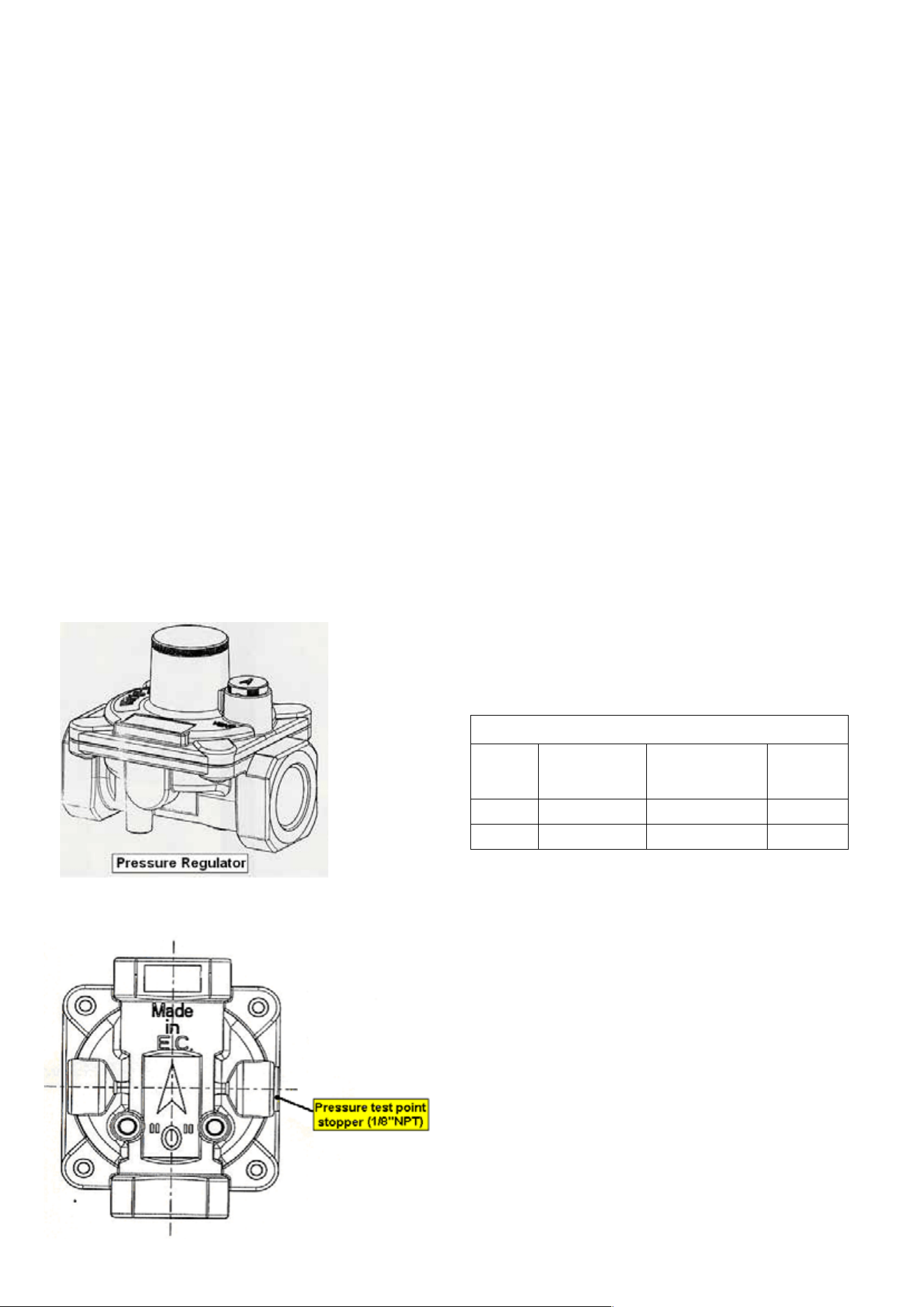
To convert the regulator (Fig.1 and Fig.2) for use with the other
gas dierent from which one it is pre-arranged it is enough
perform the following operations:
- Unscrew by hand the upper metal stopper of the regulator.
- Unscrew by hand the white plastic piece screwed under the
above mentioned metal stopper, aerward screw it again
in opposite way under the metal stopper(for gas reference
see the written “LP” and “NAT” with relative indicating
arrows on the white piece).
- Screw again by hand the metal stopper in the original
position on the regulator. Operating in this way the gas
regulator is converted for use with the other gas/pressure
-
Fig. 1 Pressure regulator
Fig. 2 Pressure regulator; pressure test-point stopper is pointed out
See the table below for GAS supply pressure requirements
Note: Cooking with the probe cannot be used in the “DEFROST,”
“QUICK START,” “PIZZA,” and “ECO” functions.
With the oven in stand-by, insert the meat probe into the
appropriate connection socket, which is usually located on
the left wall of the oven. The display will show “MEAt” for 2
seconds, and the probe symbol will start flashing. Then, the
default probe temperature value (75°C) will appear on the
display. Turn and then press the control knob to select the
desired end cooking temperature between the two limits of
40°C and 100°C (internal temperature of the food). After 4
seconds from the last setting, the chosen temperature will be
stored, and the probe symbol will remain lit. Turn on the oven,
select the cooking function, and set the desired temperature
using the appropriate knobs. The temperature read by the
probe will then appear on the display. When the programmed
probe temperature is reached, the oven will turn off, an audible
signal will sound, “End” will flash on the display, and the oven
will switch to “cooking finished” mode.
During cooking, it is always possible to modify the probe
temperature by pressing the knob 3 times and then turning the
control knob.
Note: If the probe is inserted into the connection socket during
cooking, the oven will turn off, and “Off” will appear on the
display.
If the probe is removed from the socket during cooking, the
oven will turn off, and “Off” will appear on the display.
Gas Supply Specications
Gaz Type
Pression
d’admission
(WC)
Min. Gas Supply
Pressure (WC)
Max. Input
Pressure
Natural 5 6 1/2 psi
PL 10 11 1/2 psi
liance must be disconnected from the GAS supply pièping
system during any pressure testing of that system.
6
BURNERS OF THE HOB
Replacement of the injectors
Procedure: SR - R
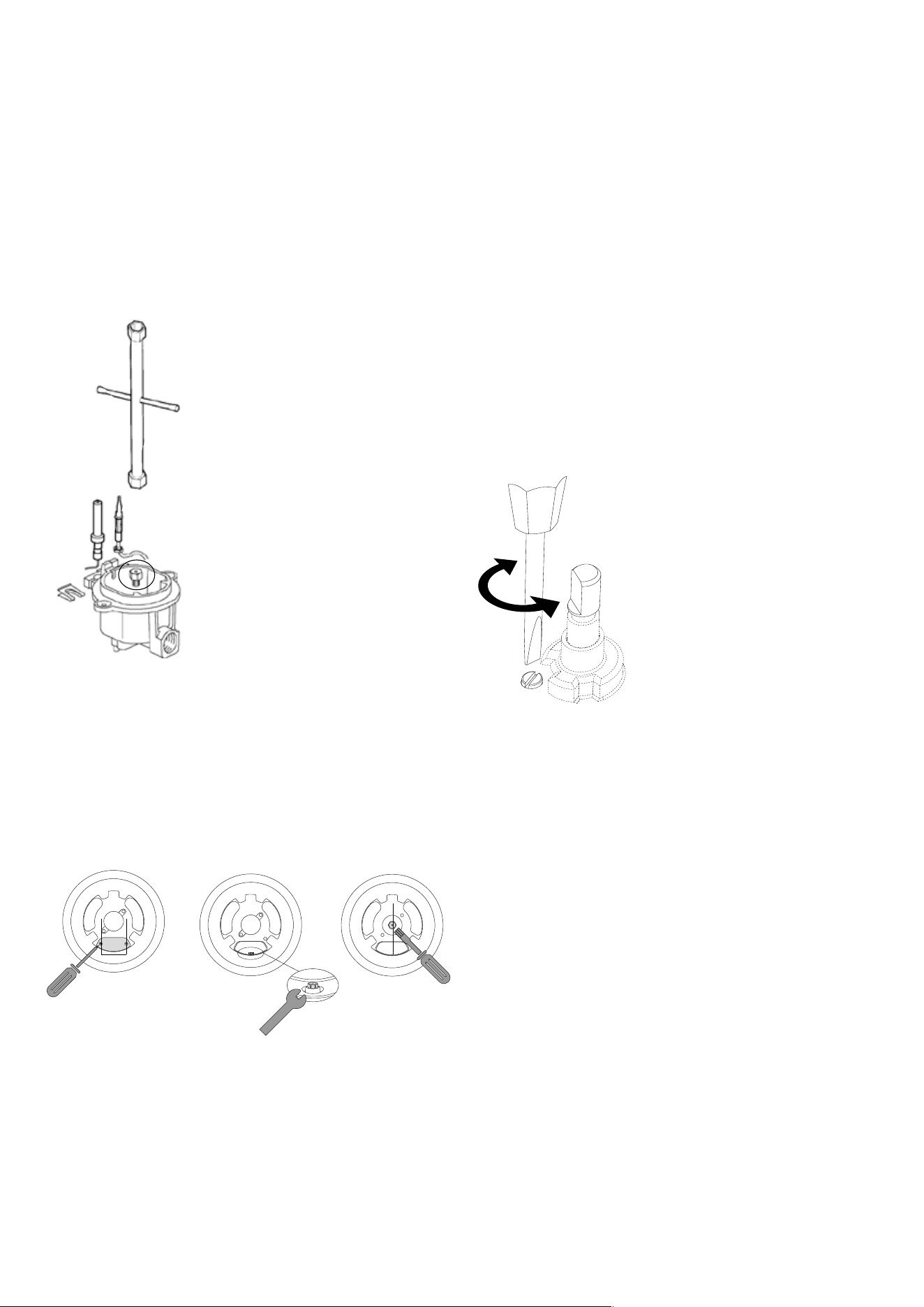
1. Remove the grill and the burners from the hob.
2. Burners SR – R:
unscrew injectors “U” using a 7 mm spanner and replace them
with those for the new gas. Save the orifices removed from the
appliance for future use.
U
Procedure: DUAL
1. Dual burners: unscrew the 2 screws “P” and remove cover
“C” fig.2.
2. unscrew injectors “U” using a 7 mm spanner and replace
them with those for the new gas. Save the orifices removed
from the appliance for future use.
Adjusting the minimum gas flow
When installing the gas cooktop you must check that the
minimum gas flow of the burners is correctly regulated. If the
type of gas is changed it is indispensable to adjust the minimum
flow. The regulating procedure is as follows.
A) Burners on the hob.
1. Light one burner at a time and turn the flame up to maximum.
2. Remove the knob of the corresponding gas tap and insert
screwdriver in the screw as showed in figure.
3. Turn the tap to minimum position.
4. Unscrew, turning to the left, to increase the flame, or screw to
the right to decrease it.
5 .If a liquid gas is used (Butane - Propane), the regulating
screw must be fully screwed in.
P
U U
7
INSTRUCTIONS FOR USE
Burners
Recommended pans according to burner size:
Burners ID Diameter Ø (cm)
Meduim SR 12 ÷ 20
Large R 20 ÷ 24
Dual - Ring DUAL 12 ÷ 30
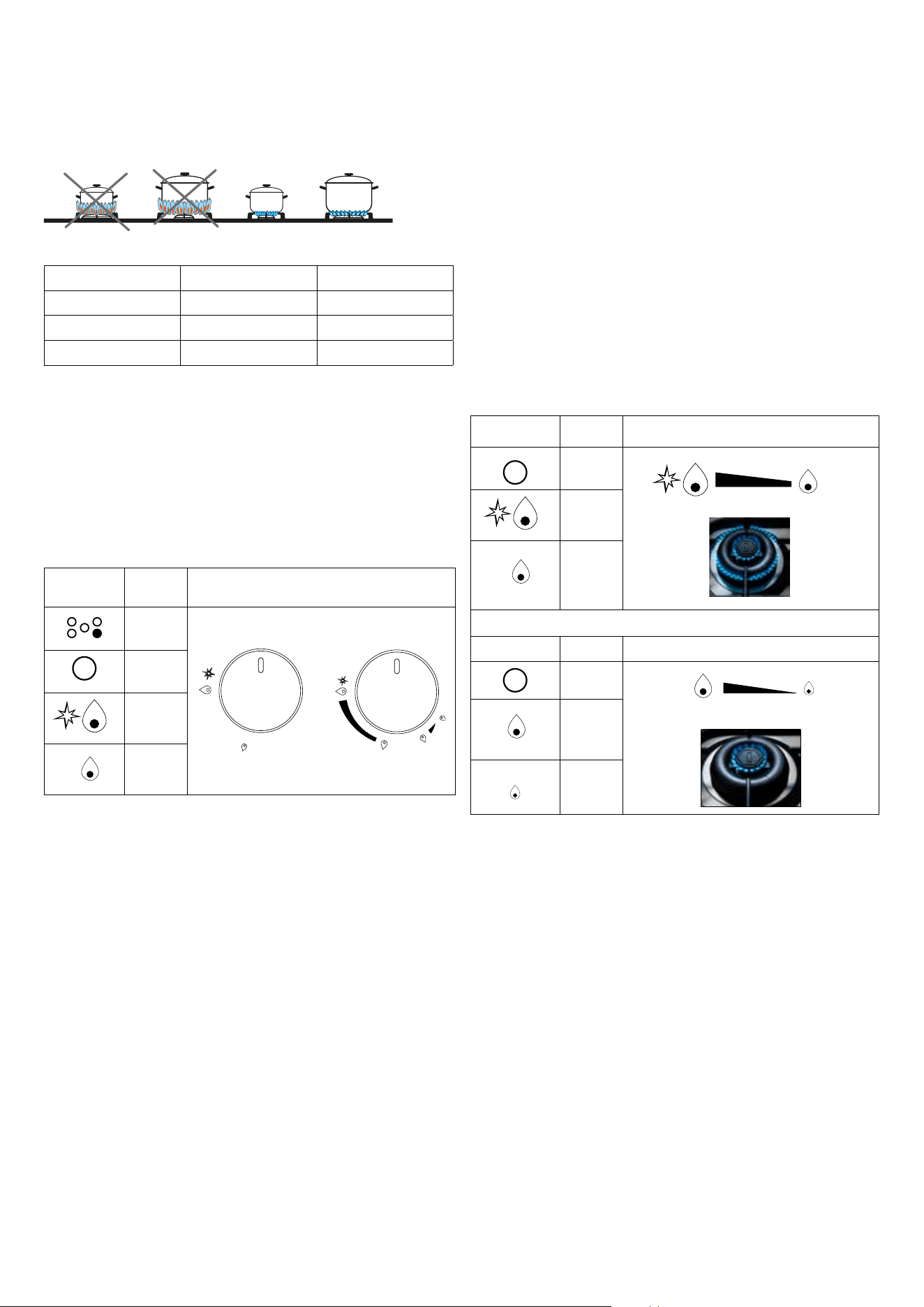
Lighting the burners
The index above the knobs will help you to find the corresponding
burner. Press the knob by turning it anti- clockwise and bring
it to the ignition position; keep the knob pressed for about 5
seconds so that upon its release the flame remains alight. In
case of unsuccessful ignition wait 5 minutes before relighting
and repeat the operation. By turning the knob, the outer
ring lights up red to indicate the GAS burner in operation
Symbol Function Knob
index
DUAL
DUAL
o
OFF
max
OFF
min
Burners “DUAL”
Identify the knob with the help of the index near the knobs.
Press and turn the knob to the symbol (maximum) for 5
seconds. Once the burner is on, by turning the knob
counterclockwise it gets to its first block that corresponds to
the middle one.
By applying a bit of force, the first block is exceeded and
the outer ring goes out leaving only the little central burner
turned on called AUXILIARY. To adjust the auxiliary burner
on minimum, rotate the knob counterclockwise until it stops.
At this point, to turn the burner back on, rotate the knob
clockwise up to the desired value.
DUAL
Symbol Function Knob
o
OFF
OFF
max
OFF
min
AUX
Symbol Function Knob
o
OFF
OFF
max
OFF
min
8
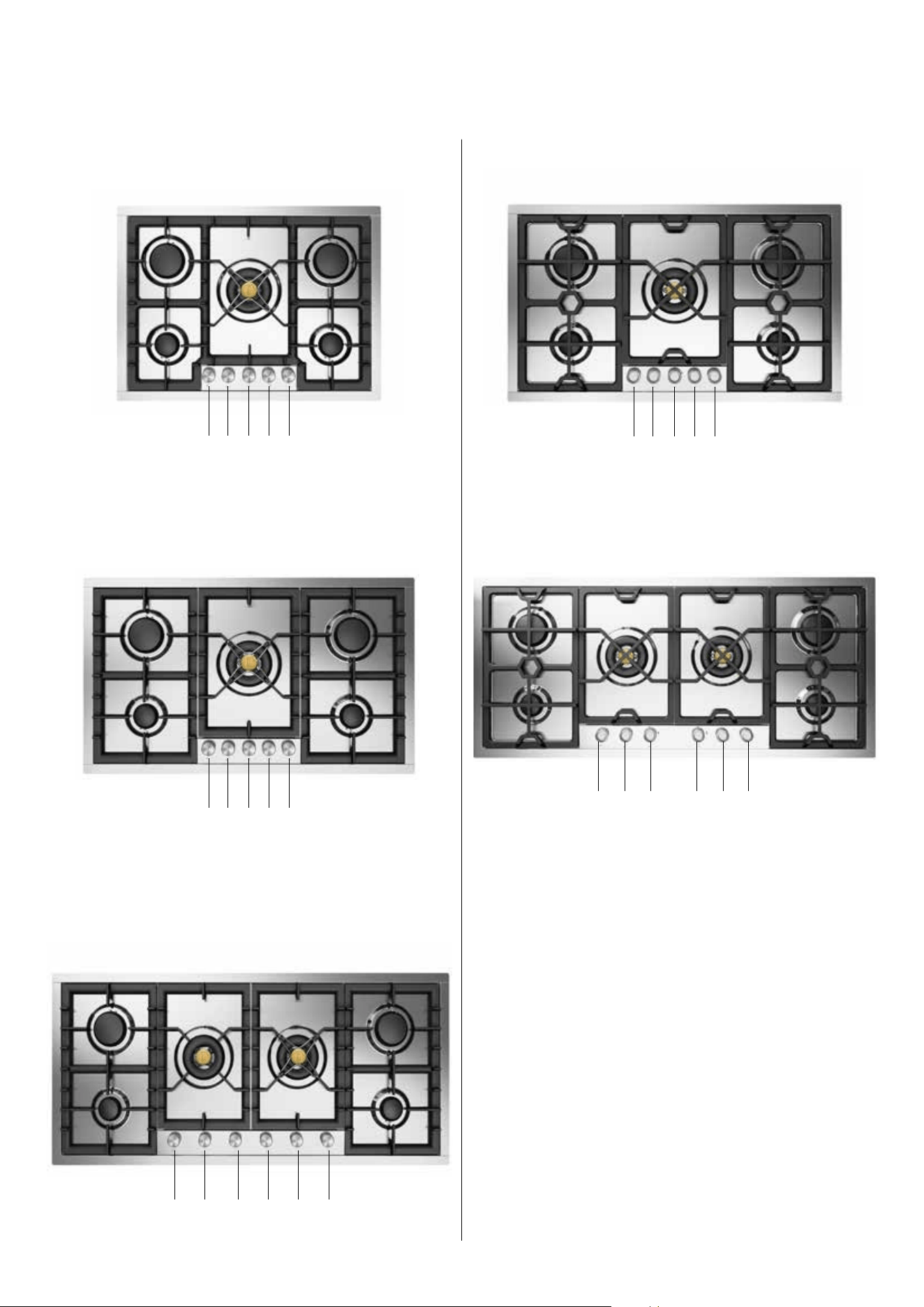
CORRECT RELATIONSHIP BETWEEN THE IGNITER
AND THE MAIN BURNER
UHC (P/PT) 75...
UHC (P/PT) 95...
UHC (PM/PMT) 95...
A CB D E
A E
B D
C
A CB D E
A
E
B D
C
A CB D E
B
C
A
D
E
UHC (P/PT) 125...
UHC (PM/PMT) 125...
A CB D FE
A
B E
F
D
C
A CB D FE
A
B
E
F
D
C
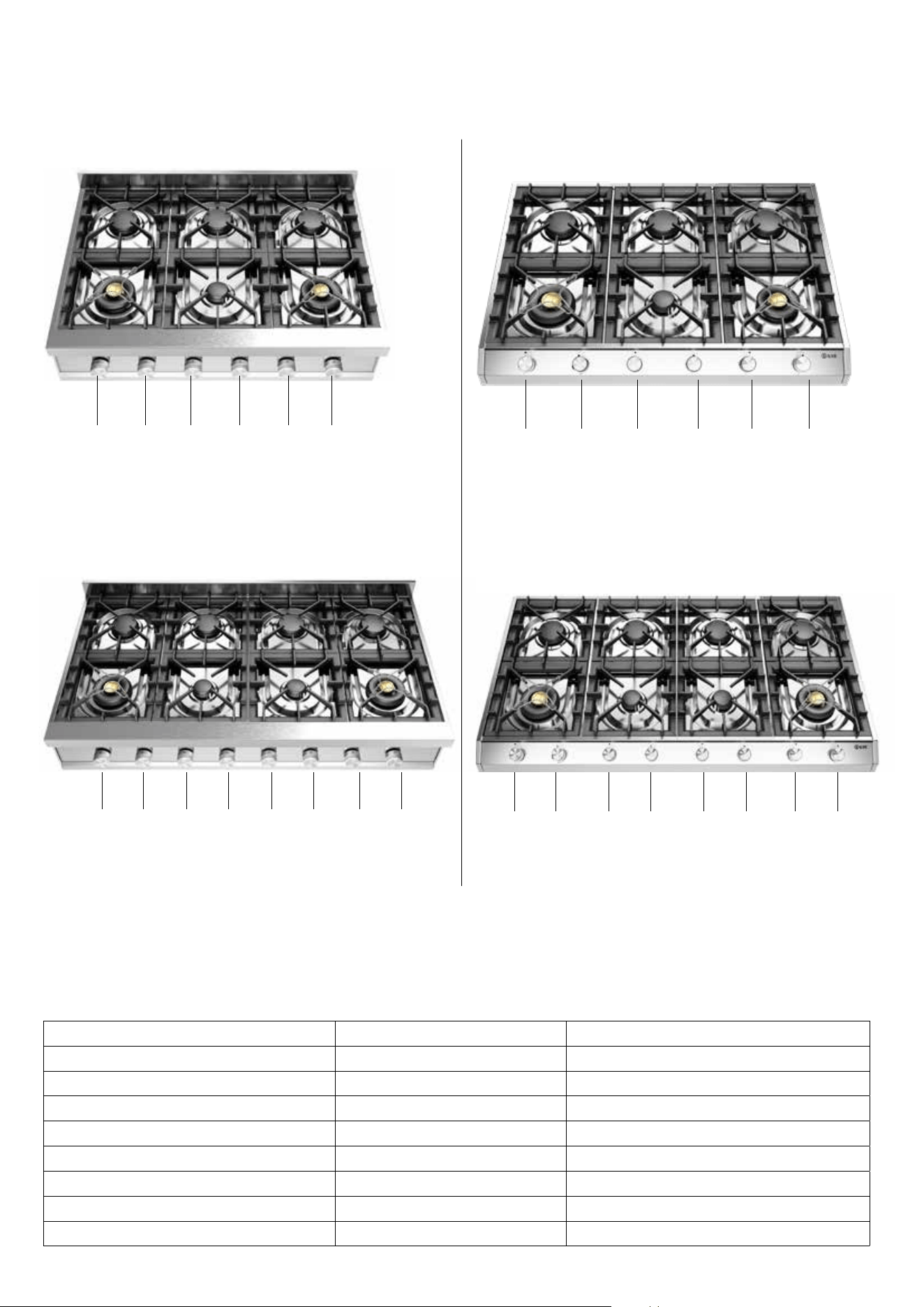
9
CORRECT RELATIONSHIP BETWEEN THE IGNITER
AND THE MAIN BURNER
Injectors for a device installed at an altitude above 2000 ft
Burner Gas Orifice size [1/100] mm
SR NATURAL (A) 117
R NATURAL (A) 141
DUAL (18000 Btu/h) NATURAL (A) 74+185
DUAL (22000 Btu/h) NATURAL (A) 74+200
SR PROPANE (E) 75
R PROPANE (E) 92
DUAL (18000 Btu/h) PROPANE (E) 50+117
DUAL (22000 Btu/h) PROPANE (E) 50+120
UHCP 965...
B
A
E
C
D
D
C
F
UHCP 1265...
UHCP 36...
UHCP 48...
A CB D F HE G
A CB D F HE G
B
A
E
G
F
H
D
C
A CB D FE
A
B
F
E
C
D
A
B F H
E GC
D
A CB D FE
10
INSTRUCTIONS TO AFFIX THE CONVERSION KIT LABEL
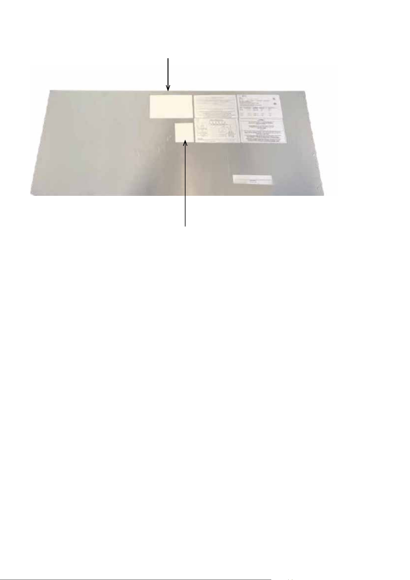
area for axing
the conversion plate
area for identication label
of the service agency making
the conversion


ilve.com
ILVE S.p.A Via Antoniana, 100 — 35011 — Campodarsego (PD) Italy
T. +39 049 9200990 / Email: [email protected]
cod. EI33960860000EN 06/2025