100366638_2000622614_REV.A
Residential Gas
Water Heater
Installaon Instrucons and
Use & Care Guide
Keep this manual in the pocket on heater for future reference whenever maintenance, adjustment or service is required.
Retain your original receipt as proof of purchase.
Residenal Atmospheric Ultra Low Nox Gas Water Heater
with the (FVIR)Flame Guard Safety System
Read this manual and the labels on the water heater before you install,
operate, or service it. If you have diculty following the direcons, or
aren’t sure you can safely and properly do any of this work yourself:
• Call our Technical Assistance Hotline at 1-800-999-9515. We can help you with in-
stallaon, operaons, troubleshoong, or maintenance. Before you call, write down
the model and serial number from the water heater’s data plate.
Incorrect installaon, operaon, or service can damage the water heater, your house
and other property, and present risks including re, scalding, electric shock, and
explosion, causing serious injury or death.
Do not store or use gasoline or other
ammable vapors and liquids in the
vicinity of this or any other appliance.
WHAT TO DO IF YOU SMELL GAS
• Do not try to light any appliance.
• Do not touch any electrical switch;
do not use any phone in your build-
ing.
• Immediately call your gas supplier
from a neighbor’s phone. Follow the
gas supplier’s instrucons.
• If you cannot reach your gas sup-
plier, call the re department.
Installaon and service must be per-
formed by a qualied installer, service
agency or the gas supplier.
WARNING: If the informaon in
these instrucons is not followed
exactly, a re or explosion may
result causing property damage,
personal injury or death.
LOW LEAD
C
O
NTENT
Table of Contents Page
IMPORTANT SAFETY INFORMATION ............................................. 3
GETTING STARTED ........................................................................ 7
INSTALLATION ............................................................................. 14
OPERATION ................................................................................. 23
TROUBLESHOOTING ................................................................... 25
MAINTENANCE ........................................................................... 31
REPAIR PARTS ............................................................................. 37
NOTES ......................................................................................... 38
February 2023
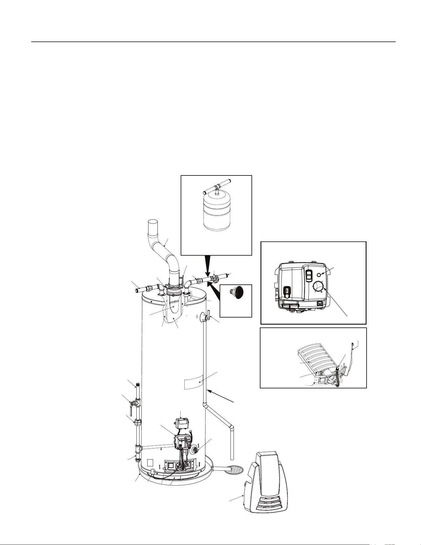
COMPLETED INSTALLATION (TYPICAL)
A Vent Pipe
B Draft Hood
C Anode (Not Shown)
D Hot Water Outlet
E Insulation
F Gas Supply Piping
G ManualGasShut-oValve
H Ground Joint Union
I Drip Leg (Sediment Trap)
* INSTALL IN ACCORDANCE
WITH LOCAL CODES.
* DRIP LEG AS REQUIRED
BY LOCAL CODES.
* DAMPER ORIENTATION
MAY VARY
J Inner Door
K Outer Door
L Union
M InletWaterShut-oValve
N Cold Water Inlet
O Inlet Dip Tube
P Temperature-PressureReliefValve
Q Rating Plate
R FlueBae
S GasControlValve/Thermostat
T DrainValve
U Pilot and Main Burner
V Flue
W Metal Drain Pan
X Igniter Wire
Y Base-Ring Filter
Z Flammable Vapor (FV) Sensor
AA LDO Module
BB Flue Damper
* ALL PIPING MATERIALS TO BE
SUPPLIED BY CUSTOMERS.
TO VENT
TERMINATION ON
ROOF
NOTE: POWER CORD NOT SHOWN.
(S) GAS CONTROL VALVE/
THERMOSTAT
GAS CONTROL/TEMPERATURE KNOB
STATUS
LIGHT
ON
OFF
STATUS
INSTALL THERMAL EXPANSION
TANK IF WATER HEATER IS
INSTALLED IN A CLOSED
WATER SYSTEM
VACUUM RELIEF
VALVE
*INSTALL PER
LOCAL CODES
MANIFOLD
TUBE
IGNITER WIRE
MAIN BURNER
PILOT ASSEMBLY
(U) MANIFOLD/BURNER ASSEMBLY
MANIFOLD DOOR
A
B
C
•
•
VERY
HOT
HOT
LOW
VAC
B
D
F
G
I
W
T
O
R
J
Q
M
N
L
E
P
Y
DISCHARGE PIPE
(DO NOT CAP OR PLUG.)
A
AA
S
BB
V
K
H
Z
Residenal Standard Gas Ultra Low Nox Water Heater Use and Care Guide • 3
SAFETY
IMPORTANT SAFETY INFORMATION
Important informaon to keep
Fill out this secon and keep this
manual in the pocket of the water
heater for reference.
Date Installed:
Model number:
Serial number:
Maintenance performed:* Date:
This is the safety alert symbol. It is used to alert you to
potenal physical injury hazards. Obey all safety mes-
sages that follow this symbol to avoid possible property
damage, serious injury or death. Do not remove any
permanent instrucons, labels, or the data plate from either the outside of
the water heater or on the inside of the access panels. Keep this manual
near the water heater.
DANGER
Read and follow all safety messages and instrucons in
this manual.
DANGER indicates hazardous situa-
on that, if not avoided, will result
in death or serious injury.
WARNING
WARNING indicates a hazardous
situaon that, if not avoided, could
result in death or serious injury.
CAUTION
CAUTION indicates a hazardous
situaon that, if not avoided, could
result in minor or moderate injury.
NOTICE
NOTICE indicates pracces not
related to physical injury.
WARNING! If the informaon in these instrucons is not followed exactly,
a re or explosion may result causing property damage, personal injury or
death. Do not store or use gasoline or other ammable vapors and liquids in
the vicinity of this or any other appliance.
An odorant is added by the gas supplier to the gas used by this water heater.
This odorant may fade over an extended period of me. Do not depend upon
this odorant as an indicaon of leaking gas. We recommend installing a fuel gas
and carbon monoxide detector.
This product is cered to comply with a maximum weighted average of 0.25%
lead content as required in some areas.
*Drain and ush tank and remove and
inspect anode rod aer rst six months
of operaon and at least annually
thereaer. Operate the Temperature
and Pressure Relief Valve (T&P) annu-
ally and inspect T&P valve every 2-4
years (see the label on the T&P valve for
maintenance schedule). See the Main-
tenance secon for more informaon
about maintaining this water heater.
4 • Residenal Standard Gas Ultra Low Nox Water Heater Use and Care Guide
SAFETY
IMPORTANT SAFETY INFORMATION
T
o reduce the risk of property
damage, serious injury or death,
read and follow the precauons below,
all labels on the water heater, and
the safety messages and instrucons
throughout this manual.
RISKS DURING
INSTALLATION AND
MAINTENANCE
Liing Risk
WARNING! The
water heater is heavy.
Follow these precau-
ons to reduce the
risk of property damage, injuries from
liing or impact injuries from dropping
the water heater.
• Use at least two people to li the
water heater.
• Be sure you both have a good grip
before liing.
• Use an appliance dolly or hand
truck to move the water heater.
Explosion Risk
WARNING! Read the water heater’s
data plate to determine the type of
gas required. Failure to follow these
instrucons can result in serious injury
or death from explosion, re or
carbon monoxide poisoning.
• Do not connect a natural gas water
heater to an L.P. gas supply.
• Do not connect an L.P. gas water
heater to a natural gas supply.
• Use a new CSA approved gas
supply line.
• Install a shut-o valve on the gas
supply line.
Gas Pressure
WARNING! The gas supply pressure
must not exceed the maximum supply
pressure as stated on the water
heater’s data plate. The minimum
supply pressure is for the purpose of
input adjustment.
RISKS DURING
OPERATION
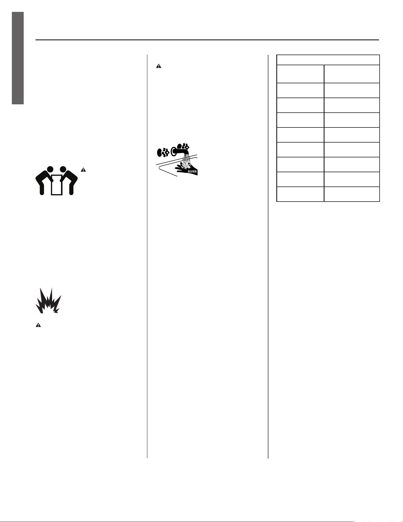
Scalding Risk
This water heater
can make water hot
enough to cause severe burns instantly,
resulng in severe injury or death.
• Feel water before bathing or
showering.
• To reduce the risk of scalding,
install Thermostac Mixing Valves
(temperature liming valves) at
each point-of-use. These valves
automacally mix hot and cold
water to limit the temperature
at the tap. Mixing valves are
available from your plumbing
contractor. Follow manufacturer’s
instrucons for installaon and
adjustment of the valves.
• The gas control valve on this water
heater has been factory set to its
lowest seng to reduce the risk
of scalding. Higher temperatures
increase the risk of scalding, but
even at 120°F, hot water can scald.
If you choose a higher tempera-
ture seng, Thermostac Mixing
Valves located at each point-of-use
are parcularly important to help
avoid scalding.
Table 1
Temperature
Time to Produce
a Serious Burn
120°F (49°C) More than 5 minutes
125°F (52°C) 1½ to 2 minutes
130°F (54°C) About 30 seconds
135°F (57°C) About 10 seconds
140°F (60°C) Less than 5 seconds
145°F (63°C) Less than 3 seconds
150°F (66°C) About 1½ seconds
155°F (68°C) About 1 second
For informaon about changing the
factory temperature seng, refer to
the “Adjusng the Temperature” sec-
on in this manual .
Even if you set the water heater’s gas
control valve to a low seng, higher
water temperatures may occur in cer-
tain circumstances:
• In some cases, repeated small draws
of water can cause the hot and cold
water in the tank to “stack” in layers.
If this happens, the water can be as
much as thirty degrees hoer than
the gas control valve seng. This
temperature variaon is the result
of your usage paern and is not a
malfuncon.
• Water temperature will be hoer if
someone adjusted the gas control
valve to a higher seng.
• Problems with the gas control valve
or other malfuncons may result in
higher than expected water tem-
peratures.
• If the water heater is in a hot envi-
ronment, the water in the tank can
become as hot as the surrounding
air, regardless of the temperature
seng.
Residenal Standard Gas Ultra Low Nox Water Heater Use and Care Guide • 5
SAFETY
IMPORTANT SAFETY INFORMATION
• If the water supplied to the water
heater is pre-heated (for example,
by a solar system) the temperature
in the tank may be higher than the
water heater’s temperature seng.
• Should overheang occur or the
burner fail to shut o, turn o the
manual gas supply valve to the water
heater and call a qualied person.
To reduce the risk of unusually hot wa-
ter reaching the xtures in the house,
install Thermostac Mixing Valves at
each point-of-use.
If anyone in your home is at parcular
risk of scalding (for example, the elder-
ly, children, or people with disabilies)
or if there is a local code or state law
requiring a certain water temperature
at the hot water tap, these precauons
are parcularly important.
According to a naonal standard (ASSE
1070) and many local plumbing codes,
the water heater’s gas control valve
should not be used as the sole means
to regulate water temperature and
avoid scalds.
Properly adjusted Thermostac Mixing
Valves installed at each point-of-use al-
low you to set the tank temperature to
a higher seng without increasing risk
of scalds. A higher temperature seng
allows the tank to provide much more
hot water and can help provide proper
water temperatures for appliances such
as dishwashers and washing machines.
Higher tank temperatures (140°F)
also kill bacteria that cause a condi-
on known as “smelly water” and can
reduce the levels of bacteria that cause
water-borne diseases.
Water Contaminaon Risk
Do not use chemicals that could con-
taminate the potable water supply. Do
not use piping that has been treated
with chromates, boiler seal, or other
chemicals.
Fire Risk
This water heater is
equipped with a
Flammable Vapor (FV)
sensor which is designed
to detect the presence of ammable
vapors. When the sensor detects those
vapors, the unit will shut down and not
operate. Even though this water heater
is ammable vapors ignion resistent
and is designed to reduce the chances
of ammable vapors being ignited,
ammable substances such as gasoline
should never be used or stored in the
same area containing a gas water
heater or other open ame or spark-
producing appliance.
Turn the gas control valve OFF and do
not operate this appliance if you sus-
pect ammable vapors have accumu-
lated inside or outside the appliance.
Immediately call a qualied person to
inspect the appliance. Water heaters
subjected to a ammable vapors inci-
dent will show a discoloraon on the
ame arrestor and require replacement
of the enre water heater. Improper
installaon or an inadequate air supply
can also cause the FVIR system to dis-
able the water heater.
To reduce the risk of a re that could
destroy your home and seriously injure
or kill people:
• Do not store things that can burn
easily such as paper or clothes next
to the water heater.
• Do not store or use gasoline or other
ammable substances in the vicinity
of this or any other appliance.
• Keep the water heater from becom-
ing wet. Immediately shut the water
heater o and have it inspected by a
qualied person if you nd that the
wiring, thermostat(s) or surround-
ing insulaon have been exposed
to water in any way (e.g., leaks from
plumbing, leaks from the water
heater itself can damage property
and could cause a re risk). If the
water heater is subjected to ood
condions or the thermostat(s) have
been submerged in water, the enre
water heater must be replaced.
• Replace the water heater’s viewport
if glass is missing or damaged. Repair
the combuson chamber door seals
if damaged.
Explosion Risk
High temperatures and
pressures in the water
heater tank can cause an explosion re-
sulng in property damage, serious in-
jury or death. A new Temperature and
Pressure (T&P) Relief Valve is included
with your water heater to reduce risk
of explosion by discharging hot water.
Addional temperature and pressure
protecve equipment may be required
by local codes.
A naonally recognized tesng labo-
ratory maintains periodic inspecon
of the valve producon process and
ceres that it meets the requirements
for Relief Valves for Hot Water Supply
Systems, ANSI Z21.22. The T&P Relief
Valve’s relief pressure must not exceed
the working pressure rang of the wa-
ter heater as stated on the rang plate.
Maintain the T&P Relief Valve properly.
Follow the maintenance instrucons
provided by the manufacturer of the
T&P Relief Valve (label aached to T&P
6 • Residenal Standard Gas Ultra Low Nox Water Heater Use and Care Guide
SAFETY
IMPORTANT SAFETY INFORMATION
Relief Valve). An explosion could occur
if the T&P Relief Valve or discharge
pipe is blocked. Do not cap or plug the
T&P Relief Valve or discharge pipe.
Fire and Explosion Risk if Hot Water is
Not Used for Two Weeks or More.
CAUTION! Hydrogen gas builds up
in a hot water system when it is not
used for a long period (two weeks or
more). Hydrogen gas is extremely
ammable. If the hot water system
has not been used for two weeks or
more, open a hot water faucet for
several minutes at the kitchen sink
before using any electrical appliances
connected to the hot water system. If
hydrogen is present there will
probably be an unusual sound such as
“air” escaping through the pipe as hot
water begins to ow. Do not smoke or
have an open ame or other ignion
source near the faucet while it is
open.
Carbon Monoxide Risk
WARNING! This water heater
operates by burning gas. Carbon
monoxide is a colorless, odorless, gas
that is a by-product
of burning of fuels
such as coal, wood,
charcoal, oil,
kerosene, propane,
and natural gas.
Breathing excessive and abnormal
amounts of carbon monoxide can
cause carbon monoxide poisoning,
resulng in serious injury or death.
This water heater must be supplied
with adequate combuson air and
must be properly vented to the
outdoors. Have a qualied person
(licensed plumber, authorized gas
company personnel, or authorized
service technician) install the venng
system using these installaon
instrucons. When the installaon is
complete, check the vent’s dra using
the instrucons on pages 23-24.
• Install a fuel gas and carbon mon-
oxide detector in the living areas
of your home.
• Do not install this water heater in
a mobile home or manufactured
housing.
• Failure to follow these instruc-
ons can result in serious injury
or death from carbon monoxide
poisoning.
Burn Risk
This water heater’s vent-
ing system can become
hot enough to burn. Do not touch the
venng system while water heater is
on, or unl the water heater is turned
o and the venng allowed to cool.
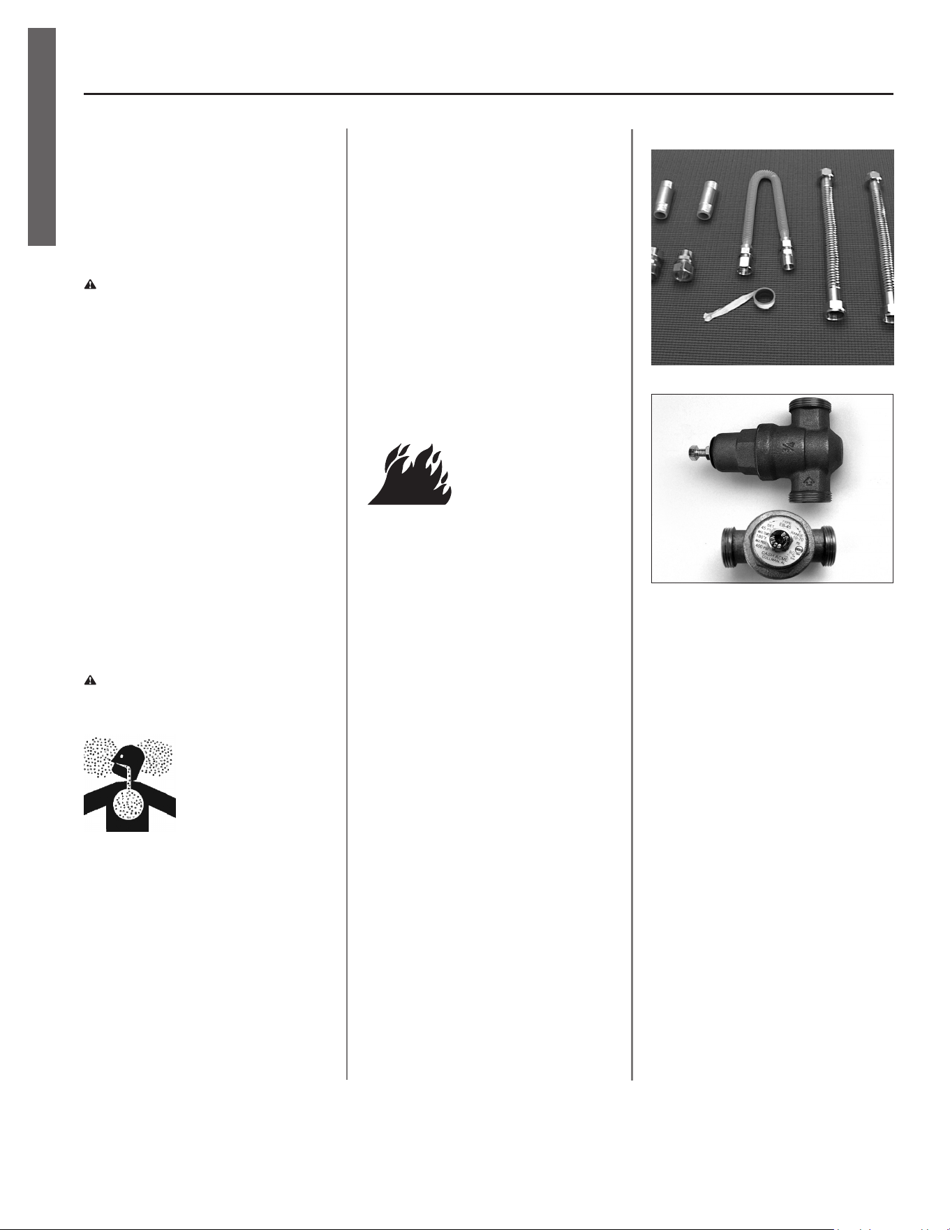
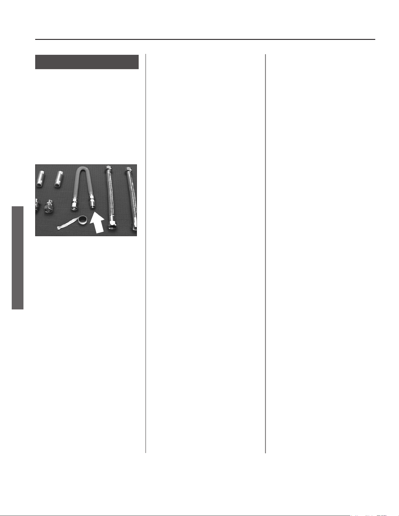
Installaon Accessories
Figure 1 - Gas Water Heater Hook-Up Kit
Figure 2 - Install a Pressure Reducing Valve set
to 50 to 60 PSI.
Residenal Standard Gas Ultra Low Nox Water Heater Use and Care Guide • 7
GETTING STARTED
GETTING STARTED
1
Review all of the instrucons
before you begin work.
Improper installaon can
damage the water heater, your home
and other property, and can present
risks of serious injury or death.
2
This water heater is design-
cered by CSA Internaonal
as a Category I, non-direct
vented water heater which takes its
combuson air either from the installa-
on area or from air ducted to the unit
from the outside. This water heater
must be installed according to all local
and state codes or, in the absence of
local and state codes, the “Naonal
Fuel Gas Code”, ANSI Z223.1(NFPA
54)-current edion. This is available
from the following:
CSA America, Inc.
8501 East Pleasant Valley Road
Cleveland, OH 44131
Naonal Fire Protecon Associaon
1 Baerymarch Park
Quincy, MA 02269
Check with local code ocials about
codes governing this installaon. Have
your installaon inspected by a code
ocial to ensure the installaon meets
all local codes.
NOTICE: If you lack the necessary skills
required to properly install this water
heater, or you have diculty follow-
ing the instrucons, you should not
proceed but have a qualied person
perform the installaon of this water
heater.
Massachuses code requires this water
heater to be installed in accordance
with Massachuses 248-CMR 2.00 and
248-CMR 5.00: State Plumbing Code.
Other local and state authories may
have similar requirements or other
codes applicable to the installaon of
this water heater.
3
Before you start, be sure you
have the following tools and
supplies:
• Common plumbing tools (depend-
ing on what type of water pipes
you have).
• Teon® tape or pipe joint com-
pound approved for potable water.
• For homes with copper pipes, you
may purchase a Gas Water Heater
Hook-Up Kit (available at most
hardware stores) with compres-
sion ngs that don’t require
soldering. This kit includes two 12”
ex water lines, two compression
ngs, an 18” exible gas line, two
nipples, and Teon® tape.
• For homes with plasc pipe, use
threaded connectors suitable for
the specic type of plasc pipe
used: CPVC or PEX (cross-linked
polyethylene). Do not use PVC
pipe.
• Non-corrosive gas leak detecon
soluon made from hand dish-
washing soap mixed with water (1
part soap to 15 parts water) or chil-
dren’s soap bubbles and a small,
so-bristled brush.
• An appliance dolly or hand truck to
move the water heater.
Recommended Accessories:
• A metal drain pan.
• Automac water leak detecon
and shut-o device.
• Pressure Reducing Valve.
• Thermal Expansion Tank.
• Thermostac Mixing Valves at each
point-of-use.
• Fuel gas and carbon monoxide
detector.
Combuson and
Venlaon Air Supply
Before installing the water heater, you
must determine the amount of air
needed to supply this water heater
and any other gas appliances in the
same area and provide adequate air for
combuson and venlaon. Consult a
qualied person if you’re unsure of the
proper way to supply air to your water
heater.
WARNING! This gas water heater
requires an adequate source of clean
air for combuson and venlaon.
Without sucient air, your water
heater will have frequent pilot outages
and may emit excessive and abnormal
amounts of carbon monoxide.
Before beginning:
Calculate total BTU/HR rang of all ap-
pliances.
To calculate the combuson air and
venlaon required, add up the total
BTU/HR rangs of all gas burning ap-
pliances (e.g., water heaters, furnaces,
clothes dryers) in the same area.
Your water heater’s BTU/HR rang is on
the data plate, located next to the gas
control valve/thermostat. The BTU/HR
rangs should be on the other appli-
ances’ data plates. If you have trouble
determining the BTU/HR rangs,
contact the manufacturer or have a
qualied person determine the venla-
on requirements. NOTICE: If you are
replacing your old water heater with
one that has a higher BTU/HR rang,
the amount of venlaon required may
be greater.
8 • Residenal Standard Gas Ultra Low Nox Water Heater Use and Care Guide
GETTING STARTED
GETTING STARTED
Example:
Gas Burning Appliance BTU/HR Rang
Gas Water Heater 40,000
Furnace 75,000
Dryer 20,000
Total 135,000
Your Appliances:
Gas Burning Appliance BTU/HR Rang
Gas Water Heater
Total
Table 2 provides examples of minimum
square footage (area) required for
various BTU/HR totals. Areas used for
storage or which contain large objects
containing less air than is assumed for
the room sizes in Table 2 – see Opon
A for more specic calculaons.
Opon A: Installaon without
outside venlaon (not recom-
mended)
Venlaon with outside air is recom-
mended for all installaons. Even if
the water heater is installed in a large,
open room inside the house, outdoor
air is usually needed because modern
homes are very ghtly sealed and
oen do not supply enough air to the
water heater. However, when installed
in a large indoor space, it may be pos-
sible to provide enough air without
outside venlaon. If you are unsure if
your installaon locaon has enough
venlaon, contact your local gas
ulity company or code ocials for a
safety inspecon.
The following instrucons will help de-
termine if it may be possible to install
without outside venlaon. Even if
this may be possible, you will need to
conduct the vent dra test on pages
23-24 when installaon is nished. If
there is not enough venlaon, you
will need to venlate with outside air.
Check for Chemicals:
Installaons where corrosive chemi-
cals may be present require outside
air. Air for combuson and venlaon
must be clean and free of corrosive or
acid-forming chemicals such as sulfur,
uorine, and chlorine. Venlaon with
outside air will reduce these chemicals,
but it may not completely eliminate
them. Failure due to corrosive chemi-
cals is not covered by the warranty.
Examples of locaons that require
outside air due to chemicals include:
• Beauty salons
• Photo processing labs
• Indoor pools
• Laundry, hobby, or cra rooms
• Chemical storage areas
Products such as aerosol sprays, de-
tergents, bleaches, cleaning solvents,
gasoline, air fresheners, paint and
varnish removers, and refrigerants
should not be stored or used near the
water heater.
A1: Calculate the air volume of
the room
Air requirements depend on the size of
the room.
Floor Area (Square feet) X Ceiling
Height (feet) = Room Volume (cubic
feet)
If there are large objects in the room
(e.g., refrigerator, furnace, car), sub-
tract their volume from the volume of
the room to get a beer esmate of
the air available.
Room Volume – Object Volume = Air
Volume
Table 2
BTU/HR Minimum Square Typical Room
Input Feet with 8’ Ceiling with 8’ Ceiling
30,000 188 9 x 21
45,000 281 14 x 20
60,000 375 15 x 25
75,000 469 15 x 31
90,000 563 20 x 28
105,000 657 20 x 33
120,000 750 25 x 30
135,000 844 28 x 30
Residenal Standard Gas Ultra Low Nox Water Heater Use and Care Guide • 9
GETTING STARTED
GETTING STARTED
A2: Calculate required air volume
A water heater installed in an unconned
ac or garage requires that the space
be at least 50 cubic feet per 1,000 BTU/
HR of the total input for all gas burning
appliances in the same area.
[Total BTU/HR/1000] x 50 = Cubic feet
of air required.
Example:
(135,000 / 1000) x 50 = 6,750
If the air volume of the room is less
than the required air volume, you must
provide two permanent outside air
openings that draw in sucient air. Use
Opon B.
If the air volume of the room is greater
than the required air volume, it may
be possible to install the water heater
without outside venlaon.
A3: Check that combuson ven-
laon is adequate
Because modern homes are oen well-
sealed to prevent dras, even a large
room may not provide enough combus-
on air without venlaon. To con-
rm that your installaon has enough
combuson air, conduct the vent dra
test on pages 23-24 when installaon is
nished.
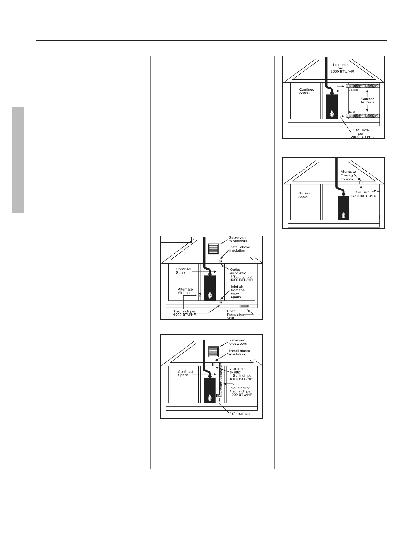
Opon B: Install with outside
venlaon
Venlaon with outside air is recom-
mended, and, for most installaons, is
needed. There may be exisng venla-
on that is adequate, or you may need
to add more venlaon.
Supplying outside air to typically requires
two openings. One opening must be
within 12 inches from the oor and
the second opening must be within 12
inches from the ceiling. Although a single
opening is not preferred, you may use a
single opening to outside air if the mini-
mum free area is sized according to Table
3. Two openings must be used when
venlang with air from another room.
The outside air can be taken from a
crawl space or ac open to the out-
doors and adequately venlated. You
may use vercal or horizontal ducts.
B2: Determine type of venlaon
There are several types of venlaon
that can be used :
1. Direct to outdoors
2. Vercal ducts
3. Horizontal ducts
4. Single opening (not recom-
mended; must be at least 100
square inches. Not appropriate
for conned spaces smaller than
50 cubic feet per 1,000 BTU/HR as
calculated in secon A or when
geng air from another room.)
5. From a larger room inside the
house (not recommended – refer
to secon A above to determine if
the combined volume of the rooms
may be adequate).
B3: Determine minimum free
area required for each vent
opening
The size of the vent openings depends
on the total BTU/HR rang of all appli-
ances in the space (use your calculaon
from “Before beginning”) and the type
of vent used. Table 3 provides the mini-
mum free area for each vent opening
depending on the type of venlaon.
B4: Calculate minimum size of
vent openings and ducts
The vent cross-seconal area needed to
provide the free area depends on the
covering on the vent openings. Typical
vents use louvers or grilles to protect
the opening. The louver or grill itself
blocks some of the free area, so the
opening may need to be larger to meet
the minimum free area requirements.
Use the following formula to calculate
the required cross-seconal area:
Cross-seconal area = minimum free
area required ÷ percent free area of
covering (in decimals – e.g., 60% = .6)
Table 3
Minimum Free Area of Permanent Openings for Venlaon and Combuson Air
Supply – All Air from Outdoors Only.
Based on the total BTU/HR input rang for all gas burning appliances within a
conned space.
Opening Source Minimum Free Area
Per Opening (sq. in.)
*Direct to outdoors 1 sq. in. per 4,000 BTU/HR (see gure on page 10)
Vercal ducts 1 sq. in. per 4,000 BTU/HR (see gure on page 10)
Horizontal ducts 1 sq. in. per 2,000 BTU/HR (see gure on page 10)
Single Opening 1 sq. in. per 3,000 BTU/HR (see gure on page 10)
*These openings connect directly with the outdoors through a venlated ac, a
venlated crawl space, or through an outside wall.
10 • Residenal Standard Gas Ultra Low Nox Water Heater Use and Care Guide
GETTING STARTED
GETTING STARTED
For example, an installaon area that
requires openings with 100 square
inches of free area would need 134
square inch openings if using metal
louvers rated at 75% free area (100 sq.
in. ÷ .75 = 134 sq. in.).
If you do not know the % free area for
your louver or grill, use the following
values:
• For wood louvers or grilles: 20%
• For metal louvers or grilles: 60%
Follow these rules to ensure that vents
and ducts provide adequate air ow:
• Each vent opening must be no
smaller than 100 square inches .
• Ducts must have the same cross-
seconal area as free area of the
opening.
• Rectangular ducts must have a
minimum dimension of no less
than three inches .
• All screens must have mesh ¼” or
larger.
• Moveable louvers must be locked
open or interconnected with the
equipment so that they open au-
tomacally during operaon.
• Keep louvers and grills clean and
free of debris or other obstruc-
ons.
B5: Check that air source is
clean and free of chemicals
Air for combuson and venlaon
must be clean and free of corrosive
or ammable chemicals. A failure due
to corrosive chemicals in the air is not
covered by the warranty. Combus-
on air must be free of acid-forming
chemicals such as sulfur, uorine, and
chlorine. Be sure that air at the vent
inlets is free of such chemicals.
B6: Check that combuson
venlaon is adequate
To conrm that your installaon has
enough combuson air, conduct the
vent dra test on pages 23-24 when
installaon is nished.
Combuson Air Supply Opons
Figure 3 - Direct to outdoors openings
Figure 4 - Vertical duct openings
Figure 5 - Horizontal duct openings
Figure 6 - Single opening
Residenal Standard Gas Ultra Low Nox Water Heater Use and Care Guide • 11
GETTING STARTED
GETTING STARTED
Venng
WARNING! Carbon Monoxide
Hazard. This water heater must be
supplied with adequate air and vented
to outdoors. The vent system must be
installed by a qualied person.
Examples of a qualied person include
gas technicians, authorized gas
company personnel, and authorized
service technicians. Failure to properly
vent the water heater can result in
severe injury or death from carbon
monoxide poisoning.
The vent system must be installed
according to local and state codes, or
in the absence of local or state codes,
the current edion of the Naonal Fuel
Gas Code, ANSI Z223.1 (NFPA 54). Do
not common vent this water heater
with any power vented appliance. Do
not use a vent damper anywhere in the
vent system of this water heater.
To reduce the risk of carbon monoxide
poisoning, install a fuel gas and carbon
monoxide detector. Install and maintain
the detector in accordance with the
manufacturer’s instrucons and local
codes.
Replacing a Water Heater Using
the Exisng Vent System
Read the “Installing a New Vent Sys-
tem” secon of this manual and make
sure your vent system is properly in-
stalled. Inspect the exisng vent system
for obstrucons, corrosion, and proper
installaon. Repair or replace if neces-
sary. The exisng vent system must be
UL listed Type B double wall or single
wall metal vent pipe of either 3 inch or
4 inch diameter and installed according
to the vent manufacturer’s instrucons
and the terms of its lisng. Do not use
other materials such as dryer vent hose.
Installing a New Vent System
The vent pipe must meet the following
specicaons:
Type of Material
UL listed Type B double wall or single
wall metal vent pipe must be used.
Local codes may be more restricve
and may not allow single wall vent pipe.
Single-wall vent pipe cannot be used for
water heaters located in acs and may
not pass through ac spaces, crawl
spaces, or any conned or inaccessible
locaon. Single-wall vent pipe cannot
pass through any interior wall.
Clearance to Combusble Materials
The vent pipe cannot pass through any
ceiling, oor, rewall, or re paron.
Any part of the vent system must main-
tain the following clearances from any
combusble materials:
• Single-wall vent pipe must main-
tain a six inch clearance from
combusble materials.
• The clearance from combusble
materials of UL listed Type B dou-
ble-wall vent pipe is specied by
the manufacturer of the vent pipe.
UL listed Type B double-wall vent
pipe may pass through walls or par-
ons constructed of combusble
material if the minimum clearance
specied by the manufacturer of
the vent pipe is maintained.
Vent Installaon
To improve the ow of exhaust gases,
we recommend that a minimum of 12
inches of vercal vent pipe be installed
on the dra hood prior to any elbow.
A poron of the vent pipe (up to 75%
of the total vercal height) can be
horizontal, but the terminaon must
be vercal. For the horizontal secon,
install without dips or sags with an
upward slope of at least ¼ inch per
foot. Install pipe avoiding unnecessary
bends. Pipe joints must be fastened by
sheet metal screws or other approved
means. Support the pipe to maintain
clearances and to avoid separaon of
joints or other damage. Vent pipe must
be accessible for cleaning, inspecon,
and replacement.
Terminaons
If local codes allow, this water heater
may be terminated into an exisng
chimney using the instrucons below.
Otherwise, this water heater’s vent
must terminate vercally (sidewall or
other horizontal terminaons are not
allowed).
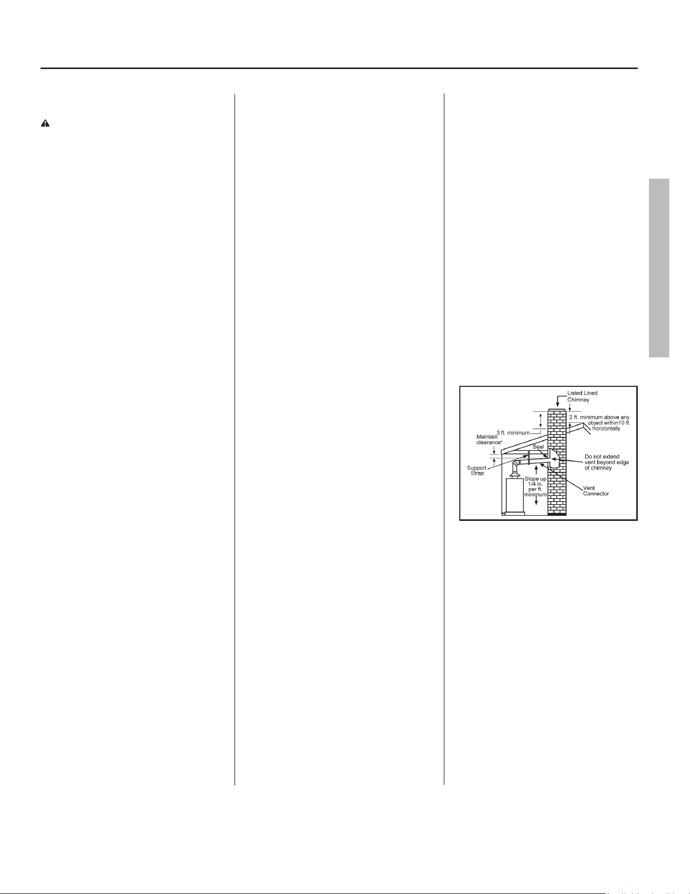
Chimney Terminaon
Figure 7 - Chimney termination vent system
NOTICE: Before connecng a vent to
a chimney, make sure the chimney
passageway is clear and free of obstruc-
ons. The chimney must be cleaned if
previously used for venng solid fuel
appliances or replaces. Also consult lo-
cal and state codes for proper chimney
sizing and applicaon or, in the absence
of local and state codes, the “Naonal
Fuel Gas Code”, ANSI Z223.1(NFPA
54)-current edion.
• The vent pipe must be installed
above the extreme boom of the
chimney to prevent potenally
blocking the ue gases.
12 • Residenal Standard Gas Ultra Low Nox Water Heater Use and Care Guide
GETTING STARTED
GETTING STARTED
• The vent pipe must be rmly at-
tached and sealed to prevent it
from falling out.
• To aid in removing the vent pipe, a
thimble or slip joint may be used.
• The vent pipe must not extend
beyond the inner edge of the
chimney as it may restrict the
space between it and the opposite
wall of the chimney.
Do not terminate the vent pipe in a
chimney that has not been cered
for this purpose. Some local codes may
prohibit the terminaon of vent con-
nectors in a masonry chimney.
Common (combined) venng is allow-
able with vercal Type B vent systems
and lined masonry chimneys as long
as proper dra for the water heater
is established under all condions of
operaon. Do not common vent this
water heater with any power vented
appliance.
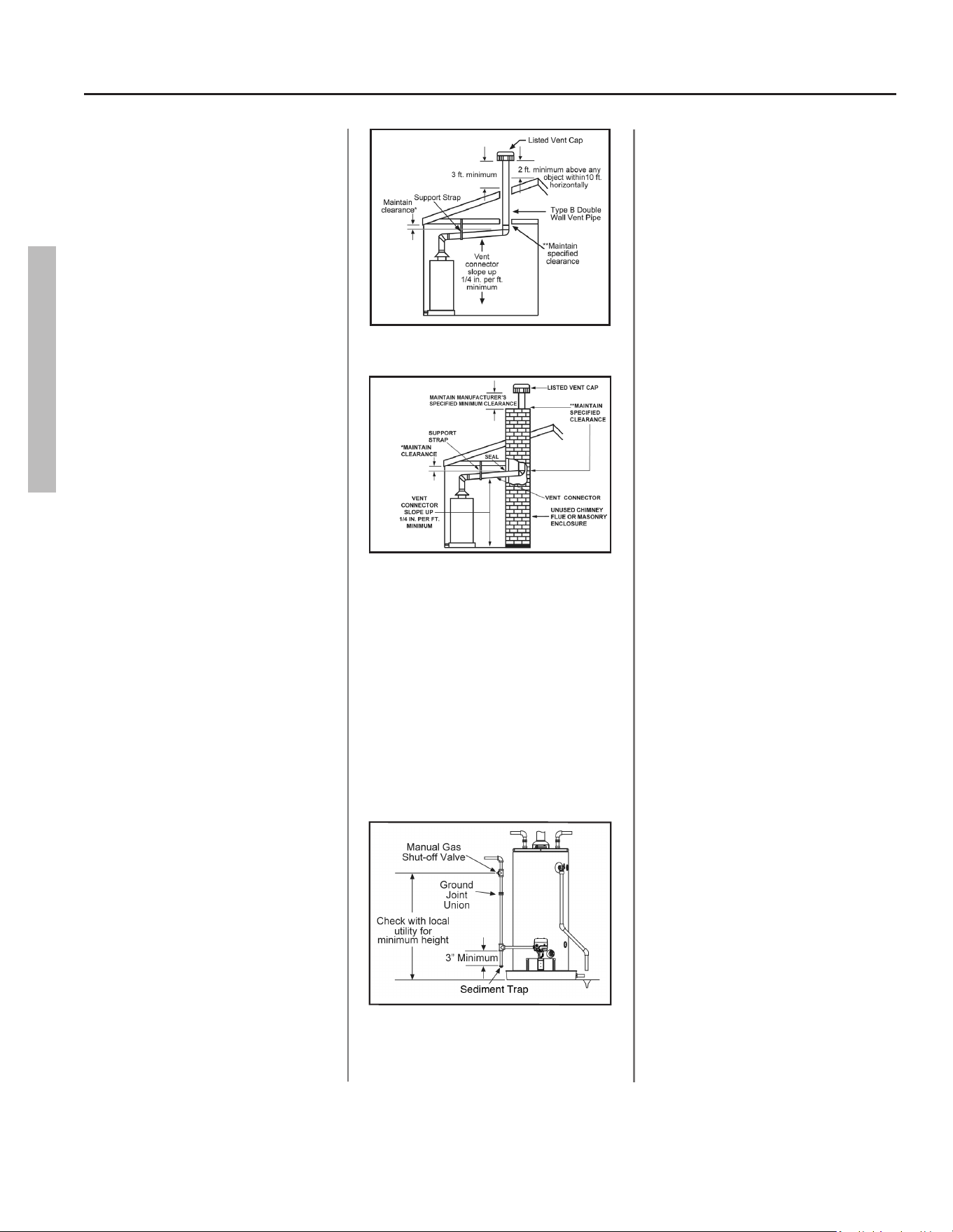
Vercal Terminaon
NOTICE: The gas vent must be termi-
nated in a vercal posion to facilitate
the removal of exhaust gases.
Vercal exhaust vents must terminate
with a listed cap or other roof assem-
bly and be installed according to their
manufacturer’s instrucons. An unused
chimney ue or masonry enclosure
may be used as a passageway for the
installaon of vent pipe. Do not com-
mon vent this water heater with any
power vented appliance. The follow-
ing gures are examples of vent pipe
system installaons and may or may
not be suitable for your specic appli-
caon. Consult the “Naonal Fuel Gas
Code”, NFPA 54, ANSI Z223.1-current
edion and local codes.
Figure 8 - Vertical gas vent system with type B
double wall vent pipe
Figure 9 - Venting through a chimney with type
B double wall vent pipe
Gas Piping
Gas piping must be installed accord-
ing to local and state codes or, in the
absence of local and state codes,
the “Naonal Fuel Gas Code”, ANSI
Z223.1(NFPA 54)-current edion.
NOTICE: When installing gas piping,
apply pipe joint compound or Teon®
tape approved for fuel gases.
Figure 10 - Gas Piping
1. Install a readily accessible manual
shut-o valve in the gas supply line
as recommended by the local ul-
ity. Know the locaon of this valve
and how to turn o the gas to this
unit.
2. Install a Sediment Trap as shown
in the Gas Piping gure below. The
Sediment Trap must be no less than
three inches long for the accumula-
on of dirt, foreign material, and
water droplets.
3. Install a ground joint union be-
tween the gas control valve and
the manual gas shut-o valve. This
is to allow easy removal of the gas
control valve.
4. Turn the gas supply on and check
for leaks. Use a small, so-bristled
brush to apply a hand dishwash-
ing soap and water mixture (1
part soap to 15 parts water) or
children’s soap bubbles to all con-
necon points of the gas piping.
Saturate all the connecons and
check for gas leaks (which will ap-
pear as small bubbles). If any leaks
are detected, ghten the appropri-
ate connecon(s) and re-check.
Gas Pressure
NOTICE: When tesng gas pipes with
a test pressure of more than ½ psi (3.5
kPa), disconnect the gas line at the
manual shut o valve and cap the gas
line. Do not subject the water heater’s
gas control valve or manual shut o
valve to more than ½ psi (3.5 kPa)
pressure for any reason. If you are
pressure tesng the gas line with test
pressure of ½ psi (3.5 kPa) or less, you
may isolate the water heater from the
gas line by closing the manual shut o
valve.
Residenal Standard Gas Ultra Low Nox Water Heater Use and Care Guide • 13
GETTING STARTED
GETTING STARTED
Space Heang
Some water heater models are equipped
with inlet/outlet connecons for use with
space heang applicaons. If this water
heater is to be used to supply both space
heang and domesc potable (drinking)
water, the instrucons listed below must
be followed.
• This water heater is suitable for
combinaon water (potable) heang
and space heang and not suitable for
space heang applicaons only.
• Be sure to follow the manual(s)
shipped with the air handler system.
• This water heater is not to be used as
a replacement for an exisng boiler
installaon.
• Do not use with piping that has been
treated with chromates, boiler seal or
other chemicals and do not add any
chemicals to the water heater piping.
• If the space heang system requires
water temperatures in excess of 120°F,
install a Thermostac Mixing Valve
in the domesc (potable) hot water
supply at each point-of-use to limit the
risk of scald injury. Install the mixing
valve per its manufacturer’s instruc-
ons.
• Pumps, valves, piping, and ngs
must be compable with potable
water.
• A properly installed ow control valve
is required to prevent thermosiphon-
ing. Thermosiphoning is the result of a
connuous ow of water through the
air handler circuit during the o cycle.
• The domesc hot water line from the
water heater should be vercal past
any mixing valve or supply line to the
air handler to remove air bubbles from
the system. Otherwise, these bubbles
will be trapped in the air handler heat
exchanger coil, reducing eciency.
• Do not connect the water heater to
any system or components previously
used with non-potable water heat-
ing appliances when used to supply
potable water.
Solar Installaon
If this water heater is used as a solar
storage heater or as a backup for the solar
system, the water supply temperatures
to the water heater tank may be in excess
of 120°F. A Thermostac Mixing Valve or
other temperature liming valve must be
installed in the water supply line to limit
the supply temperature to 120°F. The
unit must be set to Standard Mode. (See
Operang Modes in Operaon secon,
pages 24 and 25.)
NOTICE: Solar water heang systems can
oen supply water with temperatures
exceeding 180°F and may result in water
heater malfuncon.
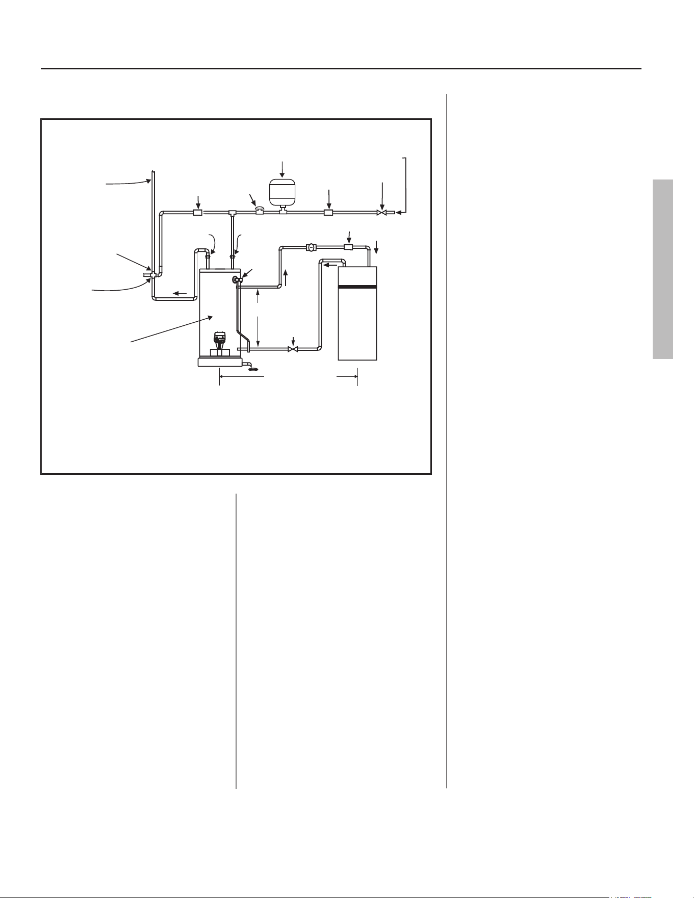
Figure 11 - Combustion Space Heating and Potable Water (Typical Installation)
IN
REMOVE A
MUST BE VERTICAL TO
IR BUBBLES
E
OUT
COIL
AIR
HANDLER
TO
AIR
HANDLER
SHUT-OFF
VALVE
*
EXPANSION TANK
VACUUM
RELIEF
VALVE
COLD WATER INLET
VA
FLOW CONTROL
LV
PUMP
*
SHUT-OFF
CHECK VALVE
†
(1/8” HOLE
DRILLED IN CLAPPER)
VALVE
CHECK
VALVE
†
TEMP/
PRESSURE
RELIEF
VALVE
TEMPERED WATER
TO FIXTURES
(MUST MEET TEMPS LISTED
IN MASS. CODE 248 CMR
†
)
MIXING VALVE
(MUST BE INSTALLED BELOW
TOP OF WATER HEATER
AS PER MANUFACTURER’S
RECOMMENDATIONS)
UNION
UNION
HOT
WATER
OUT
*
MASSACHUSETTS INSTALLATION REQUIREMENTS:
1.) CONNECT ELECTRONICALLY-CONTROLLED TIMER TO AN ALL-BRONZE PUMP. PUMP MUST ACTIVATE EVERY 6 HOURS
FOR 60 SECONDS. TURN PUMP TIMER OFF BEFORE CLOSING PIPING LOOP SHUT-OFF VALVE.
2.) ALL WATER PIPING MUST BE INSTALLED AND INSULATED IN ACCORDANCE WITH MASSACHUSETTS CODE (248 CMR
& 780 CMR).
3.) PIPING LOOP BETWEEN WATER HEATER AND AIR HANDLER MUST BE INSTALLED IN COMPLIANCE WITH 248 CMR.
† REQUIRED FOR MASSACHUSETTS.
‡ PIPING FROM THE TOP OF THE WATER HEATER WITH TEES IS ACCEPTABLE.
WATER HEATER ACCEPTED
BY THE BOARD FOR
INSTALLATION IN
MASSACHUSETTS.
†
TYPICAL MIXING VALVE INSTALLATION
COMBINATION SPACE HEATING / POTABLE WATER HEATING SYSTEM
SEE
NOTE ‡
100’-0” MAXIMUM DISTANCE
FROM WATER HEATER
TO FAN COIL AND BACK
(DEVELOPED LENGTH) NOT
INCLUDING COIL IN HEATING UNIT.
†
14 • Residenal Standard Gas Ultra Low Nox Water Heater Use and Care Guide
INSTALLATION
INSTALLATION
Step 1:
✓
Verify that your
home is equipped
and up-to-date for
proper operaon
Installing a new water heater is the
perfect me to examine your home’s
plumbing system and make sure the
system is up to current code stan-
dards. There have likely been plumb-
ing code changes since the old water
heater was installed. We recommend
installing the following accessories
and any other needed changes to
bring your home up to the latest code
requirements. Updang your plumb-
ing system can help extend the life of
your water heater, avoid damage to
your home and property, and reduce
the risk of serious injuries or death.
Inspect your home and install any de-
vices you need to comply with current
codes and assure that your new water
heater performs at its best. Check
with your local plumbing ocial for
more informaon.
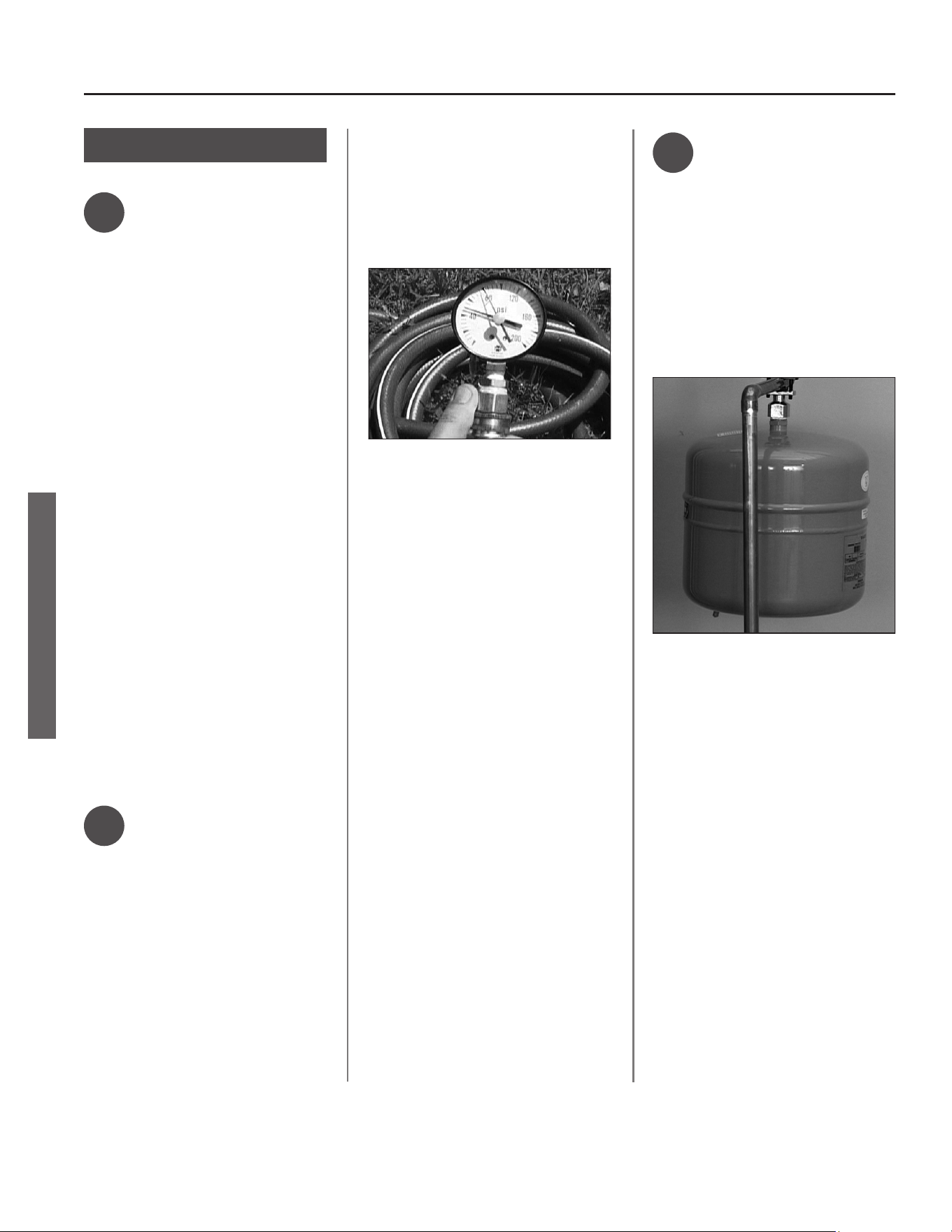
✓
Water pressure
Most codes allow a maximum
incoming water pressure of 80 psi
(we recommend a working pressure
no higher than 50-60 psi). Check your
home’s water pressure with a pressure
gauge and adjust if necessary. High
water pressure can damage the water
heater, piping, and other appliances.
HOW: Purchase an inexpensive
water pressure gauge available at
most hardware stores. at your local
plumbing supplier. Connect the water
pressure gauge to an outside faucet
and measure the maximum water
pressure experienced throughout a
24-hour period (highest water pres-
sures oen occur at night).
Figure 12 - Use a Water Pressure Gauge to make
sure your home’s water pressure is not too
high.
To adjust your home’s water pressure:
Locate your home’s Pressure Reduc-
ing Valve (PRV) on the main incoming
(cold) water supply line and adjust the
water pressure control to between
50 and 60 psi. If your home does not
have a Pressure Reducing Valve, install
a PRV on the home’s main water sup-
ply line and set it to between 50 and
60 psi. Pressure Reducing Valves are
available at most hardware stores.
your local plumbing supplier.
BACKGROUND: Over the years,
many ulies have increased water
supply pressures so they can serve
more homes. In some homes today,
pressures can exceed 100 psi. High
water pressures can damage water
heaters, causing premature leaks. If
you have replaced toilet valves, had
a water heater leak, or had to repair
appliances connected to the plumb-
ing system, pay parcular aenon
to your home’s water pressure. When
purchasing a PRV, make sure the PRV
has a built-in bypass.
✓
Water pressure
increase caused
by thermal expansion
Verify that you have a properly sized
Thermal Expansion Tank. We recom-
mend installing an expansion tank if
your home does not have one. Plumb-
ing codes require a properly pressur-
ized, properly sized Thermal Expan-
sion Tank in almost all homes.
Figure 13 - A Thermal Expansion Tank helps
protect the home’s plumbing system from pres-
sure spikes.
HOW: Connect the Thermal Expan-
sion Tank (available at most hardware
stores.) to the cold water supply line
near the water heater. The expansion
tank contains a bladder and an air
charge. To work properly, the Thermal
Expansion Tank must be sized accord-
ing to the water heater’s tank capacity
and pressurized to match the home’s
incoming water pressure. Refer to
the instrucons provided with the
Thermal Expansion Tank for installa-
on details.
BACKGROUND: Water expands when
heated, and the increased volume
of water must have a place to go, or
thermal expansion will cause large
Residenal Standard Gas Ultra Low Nox Water Heater Use and Care Guide • 15
INSTALLATION
INSTALLATION
increases in water pressure (despite
the use of a Pressure Reducing Valve
in the home’s main water supply line).
The Safe Drinking Water Act of 1974
requires the use of backow preven-
ters and check valves to restrict water
from your home reentering the public
water system. Backow preventers are
oen installed in water meters and
may not be readily visible. As a result,
most all plumbing systems today are
now “closed,” and almost all homes
now need a Thermal Expansion Tank.
A Thermal Expansion Tank is a prac-
cal and inexpensive way to help avoid
damage to the water heater, washing
machine, dishwasher, ice maker, and
even toilet valves. If your toilet oc-
casionally runs for no apparent reason
(usually briey at night), that may be
due to thermal expansion increasing
the water pressure temporarily.
✓
Water Pipe and
Tank Leaks
METAL
DRAIN
PAN
AT LEAST 2” GREATER THAN THE
DIAMETER OF THE WATER HEATER.
PIPED TO AN
ADEQUATE DRAIN
6” MAXIMUM
AIR GAP
DISCHARGE PIPE
(DO NOT CAP OR PLUG)
Figure 14 - A metal drain pan piped to an ad-
equate drain can help protect flooring from leaks
and drips.
Leaks from plumbing pipes or from the
water heater itself can damage prop-
erty and could cause a re risk.
• Install an automac leak detec-
on and shuto device (available at
your local plumbing supplier). These
devices can detect water leaks and
can shut o the water heater’s water
supply if a leak occurs.
• Install a metal drain pan (available at
most hardware stores at your local
plumbing supplier) under the water
heater to catch condensaon or
leaks from the piping connecons
or tank. Most codes require, and
we recommend, installing the water
heater in a metal drain pan that is
piped to an adequate drain. The
drain pan must be at least two inches
wider than the diameter of the
water heater. Install the drain pan
so the water level would be limited
to a maximum depth of 1-3/4”. The
pan must not restrict air ow to the
burner.
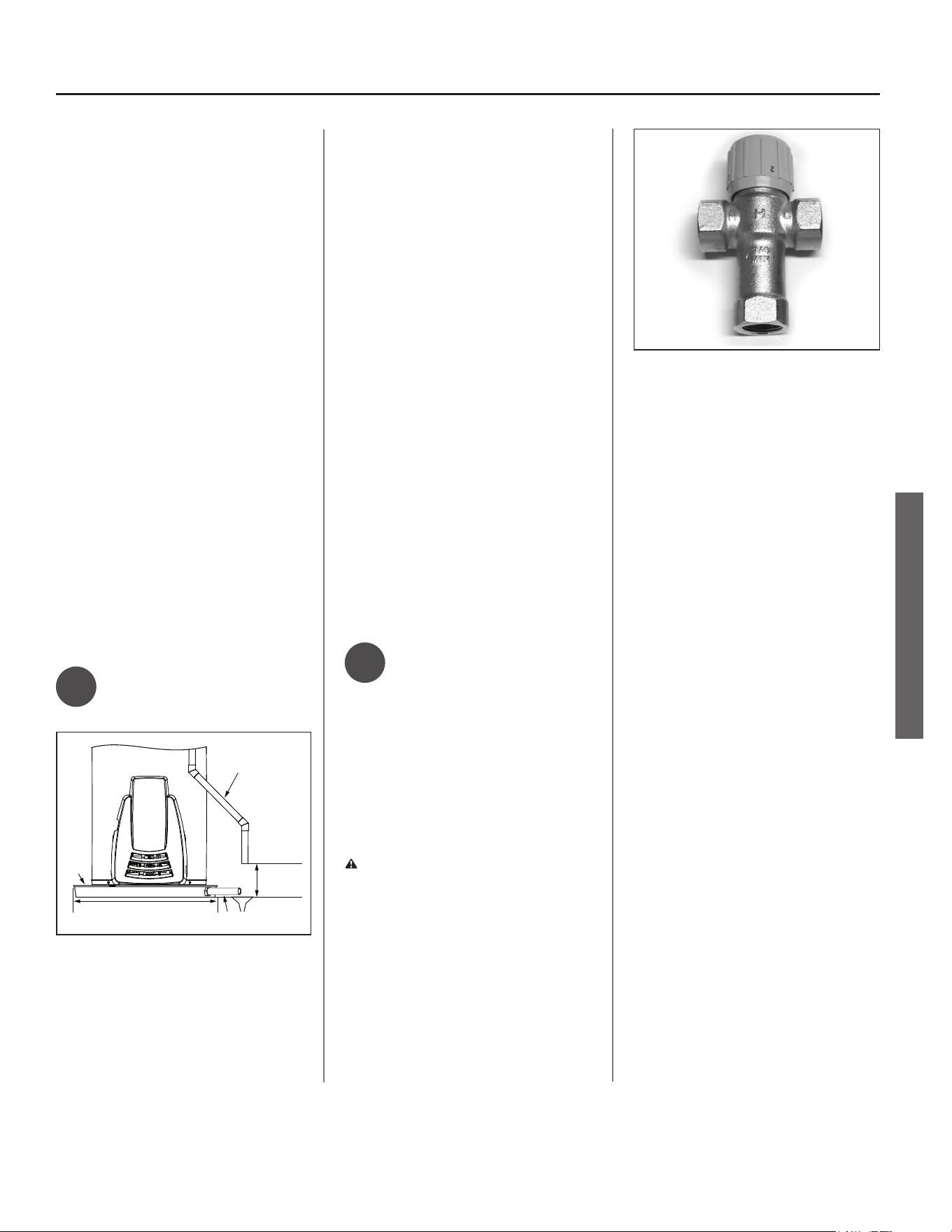
✓
Water Tempera-
ture Regulaon
Install Thermostac Mixing Valves to
regulate the temperature of the water
supplied to each point-of-use (for
example, kitchen sink, bathroom sink,
bath, shower). Install and adjust the
mixing valve according to its manufac-
turer’s instrucons.
WARNING! Even if the water
heater’s thermostat is set to a rela-
vely low temperature, hot water can
scald. Install Thermostac Mixing
Valves at each point-of-use to reduce
the risk of scalding.
Figure 15 - Thermostatic Mixing Valves installed
at each point-of-use can help avoid scalding
BACKGROUND: A Thermostac Mixing
Valve, installed at each point-of-use,
mixes hot water from the water heater
with cold water to more precisely
regulate the temperature of hot water
supplied to xtures. If you aren’t sure
if your plumbing system is equipped
with properly installed and adjusted
Thermostac Mixing Valves at each
point where hot water is used, contact
a qualied person.
16 • Residenal Standard Gas Ultra Low Nox Water Heater Use and Care Guide
INSTALLATION
INSTALLATION
Step 2:
Verify that the locaon
is appropriate
WARNING! Do not store or use
ammable materials, vapors, or
liquids in the same locaon where this
water heater is installed.
Before installing your water heater,
ensure that it will be located:
• Indoors in an area with adequate
air supply.
• In an area that will not freeze.
• As close as possible to a chimney
or vent.
• In a metal drain pan piped to an
adequate drain.
• In an area suitable for vercal
installaon.
• In an area with adequate space
(clearances) for periodic servicing
(there must be a minimum of 24
inches of front clearance).
• In an area that allows a minimum
clearance from combusble sur-
faces as stated on the data plate.
• On a oor that can support the
weight of a water heater full of
water.
• Within 19 feet of a 120VAC outlet.
Do not use an extension cord.
You will also want to follow these
guidelines while considering an appro-
priate locaon:
• Do not install near air-moving
devices such as exhaust fans,
venlaon systems, or clothes
dryers.
• Do not obtain venlang air for
the furnace/air handler from the
same space as the water heater.
Ensure that any return air ducts
near the water heater are sealed.
• If the water heater is located
in an area subject to lint, dust,
or oily vapors, at least annually
check and clean the air lter. See
Maintenance secon for steps on
cleaning the air lter.
• Do not install in a bathroom,
bedroom, or any occupied room
normally kept closed.
• If the water heater is installed di-
rectly on carpeng, it shall be in-
stalled on a metal or wood panel
extending beyond the full width
and depth of the water heater
by at least 3 in (76.2mm) in any
direcon. If the water heater is
installed in an alcove or closet,
the enre oor shall be covered
by the aforestated panel.
• If your area is prone to earth-
quakes, use special straps as
required by local building codes.
NOTICE: The state of California re-
quires bracing, anchoring, or strap-
ping the water heater to avoid its
moving during an earthquake. Contact
local ulies for code requirements in
your area, visit hp://www.dsa.dgs.
ca.gov, or call 1-916-445-8100 and
request instrucons. Other locaons
may have similar requirements. Check
with your local and state authories.
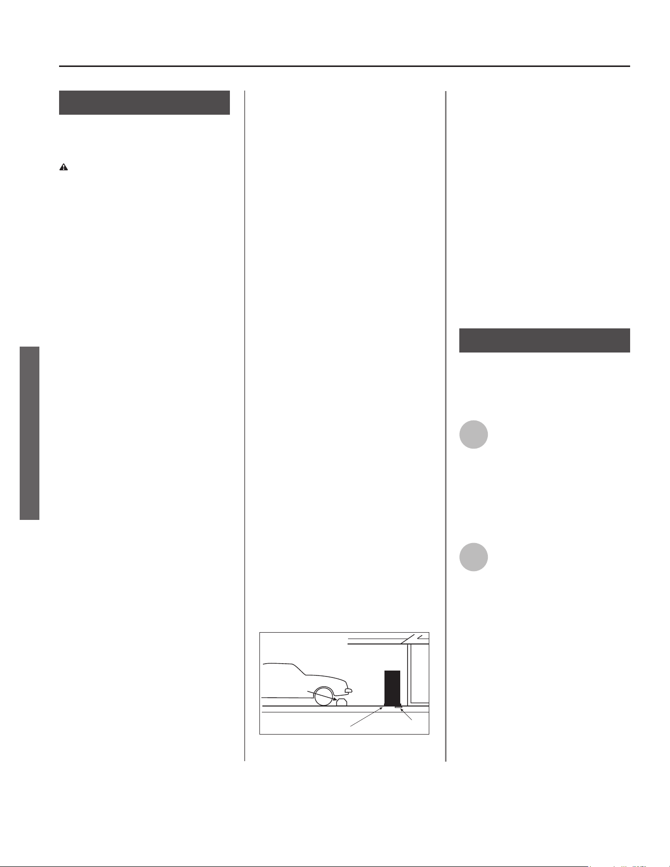
• Do not install in a locaon prone
to physical damage by vehicles,
ooding, or other risks.
Vehicle
Stop
Drain
Drain
Pan
Figure 16 - In a garage, install a vehicle stop to
avoid water heater damage.
• Avoid locaons such as acs, up-
per oors, or where a leak might
damage the structure or furnish-
ings. Due to the normal corrosive
acon of water, the tank will
eventually leak. To minimize prop-
erty damage from leaks, inspect
and maintain your water heater
in accordance with this manual’s
instrucons. Install a metal drain
pan under the water heater piped
to an adequate drain. Inspect the
drain pan, pipes, and surrounding
area regularly and x any leaks
found.
Step 3:
Removing the old
water heater
1
Read each installaon step and
decide if you have the neces-
sary skills to install the water
heater. Only proceed if you are comfort-
able you can safely perform the work. If
you are not sure, have a qualied person
perform the installaon.
2
On the old water heater, turn
the control knob on the gas
control valve to the
OFF posion. See Figure 17.
Residenal Standard Gas Ultra Low Nox Water Heater Use and Care Guide • 17
INSTALLATION
INSTALLATION
Gas
control
knob
Figure 17 - Turn gas control/temperature knob OFF.
3
Turn the manual gas valve for
the water heater’s supply line
OFF.
4
Open a hot water faucet and
let the hot water run unl it is
cool (This may take 10 min
utes or longer).
Figure 18 - Let the hot water run until it is cool.
WARNING! Be sure the water runs
cool before draining the tank to reduce
the risk of scalding.
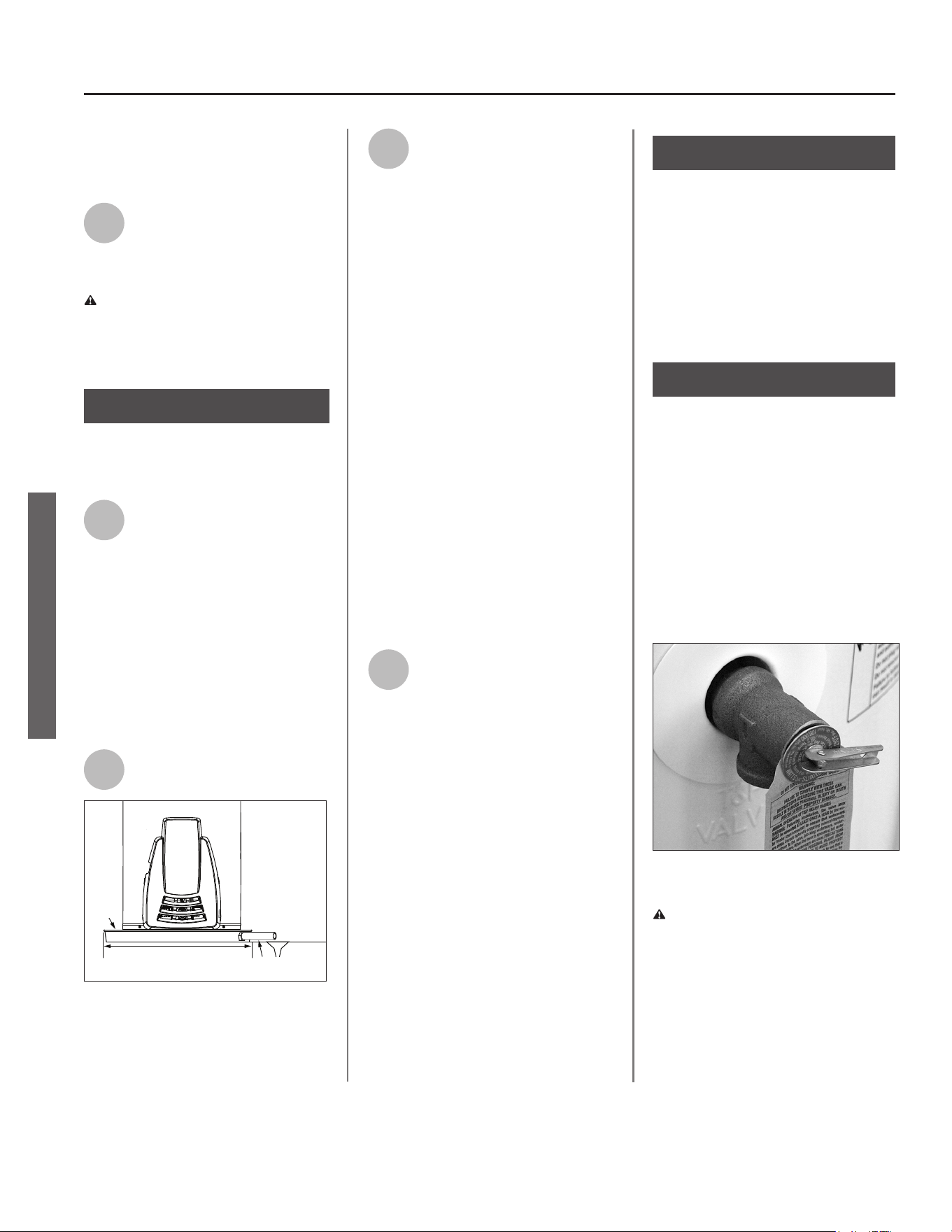
5
Connect a garden hose to the
drain valve and place the
other end of the hose in a
drain, outside, or in buckets. (Sedi-
ment in the boom of the tank may
clog the valve and prevent it from
draining. If you can’t get the tank to
drain, contact a qualied person.)
6
Turn the cold water supply
valve OFF.
Figure 19 - Cold water supply in off position.
7
Using a standard at-blade
screwdriver, open the drain
valve. Sediment build up in
the boom of the water heater may
hinder or prevent draining.
Figure 20 - Draining the old water heater.
8
Also open a hot water faucet
to help the water in the tank
drain faster.
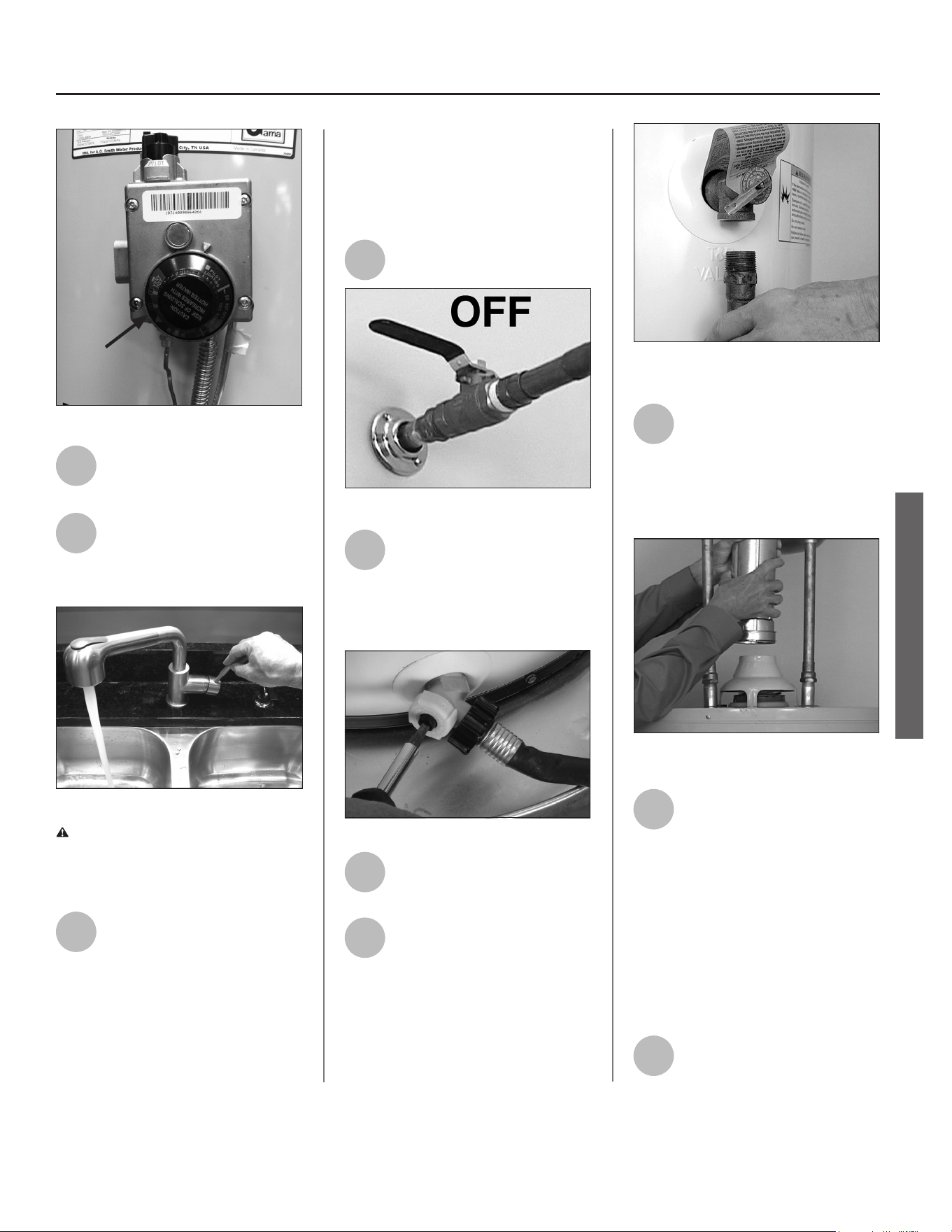
9
When the tank is empty,
disconnect the Temperature &
Pressure (T&P) Relief Valve
discharge pipe. You may be able to
reuse the discharge pipe, but do not
reuse the old T&P Relief Valve. A new
T&P Relief Valve comes with your new
water heater.
Figure 21 - Removing the T&P Relief Valve
discharge pipe.
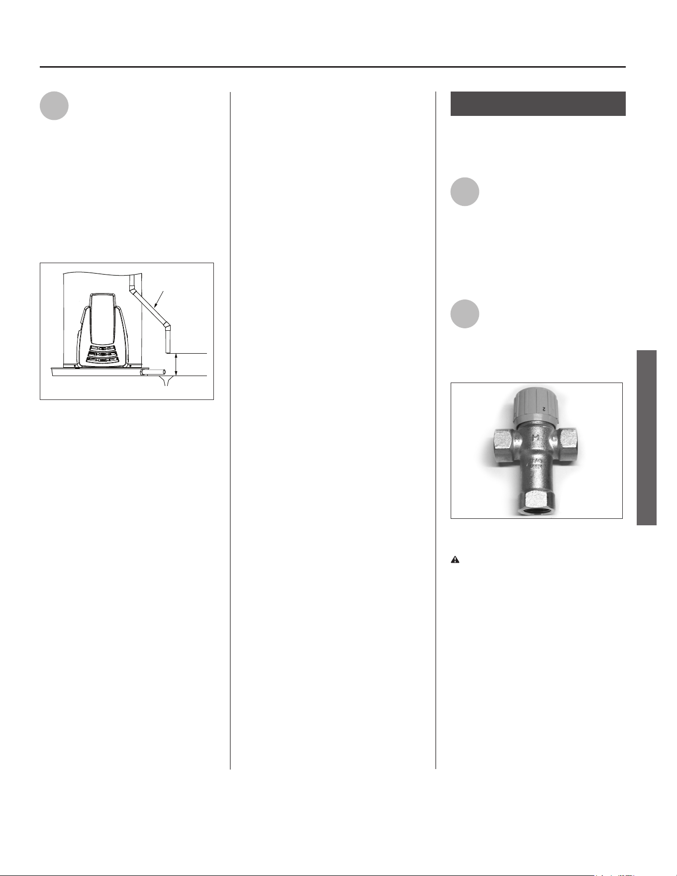
10
Allow the vent pipe and dra
hood to cool. Once cooled,
disconnect the vent pipe from
the dra hood. You may need to
support the vent pipe unl the new
water heater is in place.
Figure 22 - Disconnect the vent pipe from the
draft hood.
11
Disconnect the water pipes.
Many water pipes are con-
nected by a threaded union
which can be disconnected with
wrenches. If you must cut the water
pipes, cut the pipes close to the water
heater’s inlet and outlet connecons,
leaving the water pipes as long as
possible. If necessary, you can make
them shorter later when you install the
new water heater.
12
Conrm the manual gas valve
for the water heater’s supply
18 • Residenal Standard Gas Ultra Low Nox Water Heater Use and Care Guide
INSTALLATION
INSTALLATION
line is turned o. Disconnect the gas
line from the water heater’s gas
control valve and cap it.
13
Remove the old water heater.
Use an appliance dolly or
hand truck to move the water
heater.
WARNING! Use two or more
people to remove or install a water
heater. Failure to do so can result in
back or other injury.
Step 4:
Installing the New
Water Heater
1
Completely read all instruc-
ons before beginning. If you
are not sure you can safely
complete the installaon, seek assis-
tance from any of the following sources:
• Schedule an appointment with
a qualied person to install your
water heater.
• Call our Technical Assistance Hotline
at 1-800-999-9515.
2
Install a metal drain pan that
is piped to an adequate drain.
METAL
DRAIN
PAN
AT LEAST 2” GREATER THAN THE
DIAMETER OF THE WATER HEATER.
PIPED TO AN
ADEQUATE DRAIN
Figure 23 - Metal drain pan piped to drain.
3
Set the water heater in place
taking care not to damage the
drain pan. When installing
directly on carpet, the water heater
must be installed on a wood or metal
base that extends beyond the dimen-
sions of the water heater (width and
depth) by at least 3 inches (76.2 mm)
in any direcon. If the water heater is
installed on carpet in an alcove or
closet, the enre oor must be covered
by a wood or metal panel.
NOTICE: Most codes require seng
the water heater in a metal drain pan
piped to an adequate drain. The drain
pan helps avoid property damage
which may occur from condensaon
or leaks in the piping connecons or
tank. The drain pan must be at least
two inches wider than the diameter
of the water heater. Install the drain
pan so the water level is limited to a
maximum depth of 1-3/4”.
4
Verify that the water heater is
set in place properly. Check
that:
• There is adequate space to install
the T&P Relief Valve discharge
pipe and that it can be piped to a
separate drain (and not into the
drain pan).
• There is adequate access and
space around the water heater
for future maintenance.
• The water heater is installed
vercally.
Step 5:
Check the Air Filter
This water heater is equipped with a
base-ring air filter. Before proceeding
to the next step, visually check the
filter to ensure it is properly seated in
the base-ring. Do not operate the
water heater without a clean air filter
in place.
Step 6:
Connect the Tempera-
ture and Pressure (T&P)
Relief Valve/Pipe
Most T&P Relief Valves are pre-
installed at the factory. In some cases,
they are shipped in the carton and
must be installed in the opening
marked “T&P Relief Valve” and ac-
cording to local codes.
Figure 24 - Temperature and Pressure Relief
Valve
WARNING! To avoid serious injury
or death from explosion, install a T&P
Relief Valve according to the following
instrucons:
Residenal Standard Gas Ultra Low Nox Water Heater Use and Care Guide • 19
INSTALLATION
INSTALLATION
1
If the T&P Relief Valve was not
factory installed, install the
new T&P Relief Valve that
came with your water heater. Do not
reuse an old T&P Relief Valve.
• The discharge pipe should be at
least 3/4” inside diameter and
sloped for proper drainage. Install
it to allow complete drainage of
both the T&P Relief Valve and the
discharge pipe.
ADEQUATE DRAIN
6” MAXIMUM
AIR GAP
DISCHARGE PIPE
(DO NOT CAP OR PLUG)
Figure 25 - Temperature and Pressure Relief
Valve Pipe (Discharge Pipe)
• The discharge pipe must not be
smaller than the pipe size of the
T&P Relief Valve. The pipe must
also be able to withstand 250°F
(121°C) without distoron. Use
only copper or CPVC pipe. Do not
use any other type of pipe, such as
PVC, iron, exible plasc pipe, or
any type of hose.
• Terminate the discharge pipe a
maximum of six inches above a
oor drain or outside the building.
Do not drain the discharge pipe
into the drain pan; instead pipe it
separately to an adequate drain.
In cold climates, terminate the dis-
charge pipe inside the building to
an adequate drain. Outside drains
could freeze and obstruct the
drain line—protect the discharge
pipe from freezing.
• Do not place any valve or other
restricon between the tank and
T&P Relief Valve. Do not cap,
block, plug, or insert any valve
between the T&P Relief Valve and
the end of the discharge pipe. Do
not insert or install any reducer in
the discharge pipe.
Step 7:
Install Shuto and Ther-
mostac Mixing Valves
1
If one is not already installed,
install a manual shuto valve
in the cold water line that
supplies the water heater. Install the
shuto valve near the water heater so
that it is readily accessible. Only use a
full-ow ball or gate valve compable
with potable water.
2
Install a Thermostac Mixing
Valve at each point-of-use (for
example, kitchen sink,
bathroom sink, bath, shower) per the
valve manufacturer’s instrucons.
Figure 26 - Install Thermostatic Mixing Valves at
each point where hot water will be used.
WARNING! Even if the water
heater’s thermostat is set to a rela-
vely low temperature, hot water can
scald. Install Thermostac Mixing
Valves at each point-of-use to reduce
the risk of scalding.
20 • Residenal Standard Gas Ultra Low Nox Water Heater Use and Care Guide
INSTALLATION
INSTALLATION
3
For water heaters that are fed
by a solar water heang
system (or any other pre-
heang system), always install a
Thermostac Mixing Valve or other
temperature liming device in the
inlet water supply line to limit water
supply inlet temperature to 120°F.
Solar water heang systems can
supply water with temperatures
exceeding 180°F and may result in
water heater malfuncon.
WARNING! Hot water provided by
solar heang systems can cause
severe burns instantly, resulng in
severe injury or death.
Step 8:
Connect the Water
Supply
Note that all piping and components
connected to the water heater must
be suitable for use with potable water.
1
Determine the type of water
pipes in your home. Most
homes use copper water
pipes, but some use CPVC or cross-
linked polyethylene (PEX). Use ngs
appropriate for the type of pipe in
your home. Do not use iron or PVC
pipe.
2
Connect the cold water
supply using 3/4 inch
Naonal Pipe Thread “NPT” to the
ng marked “C” (COLD).
For ease of removing the water heater
for service or replacement, con-
nect the water pipes with a coupling
called a union. We recommend using
a dielectric-type union (available at
your local plumbing supplier). Dielec-
tric unions can help prevent corro-
sion caused by ny electric currents
common in copper water pipes and
can help extend the life of the water
heater
IF YOU HAVE COPPER PIPES:
If your home has copper water pipes,
you can solder the water pipe connec-
ons or use compression ngs which
don’t require soldering. Compression
ngs are easier to install than solder-
ing pipe. Check with local plumbing
ocials to determine what types of
pipe materials are suitable for your
locaon. Do not use lead-based solder.
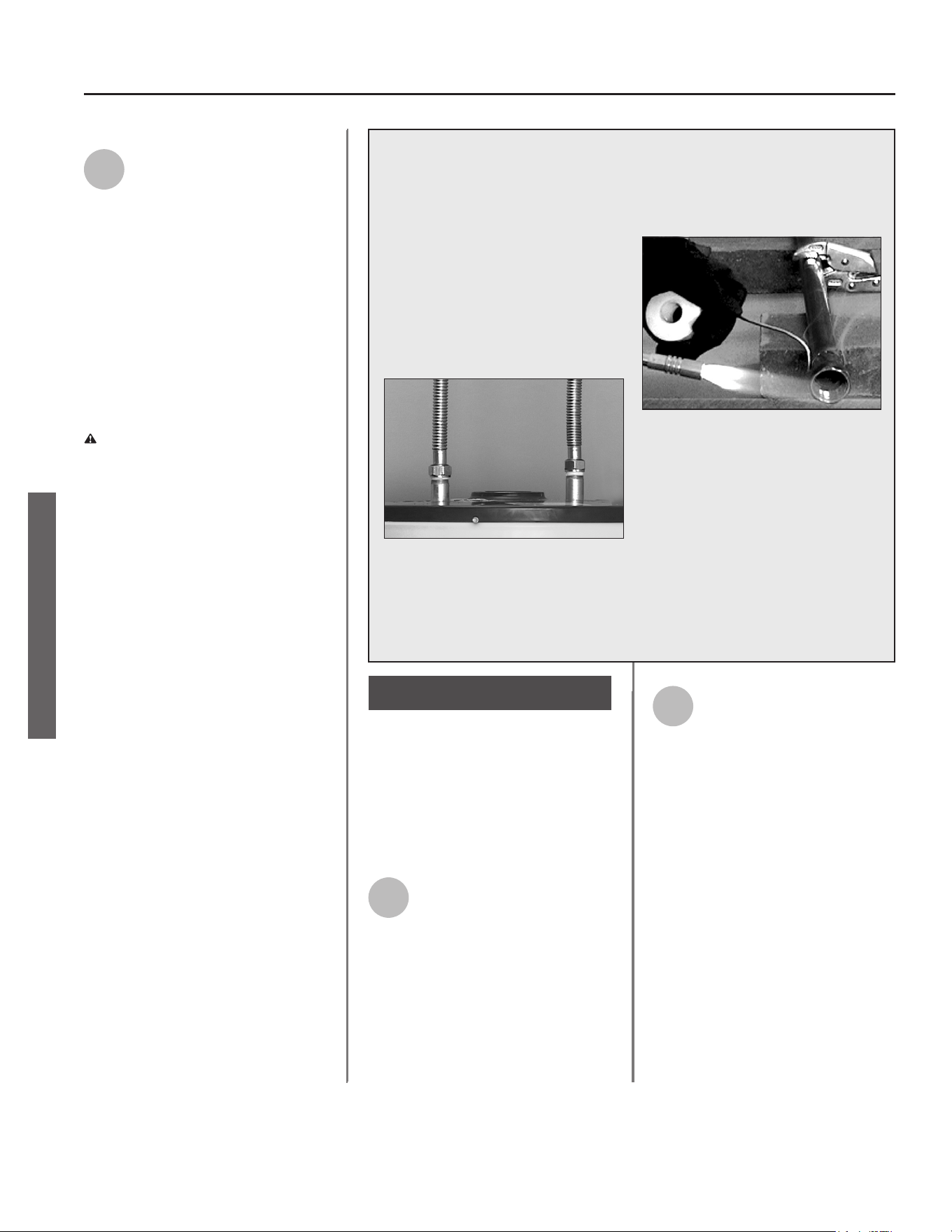
NOTICE: Do not solder pipes while
they are aached to the water heater.
The water heater’s inlet and outlet
connecons contain non-metallic parts
which could be damaged. The proper
way to connect the water heater to
copper water pipes is as follows:
• Solder a short length of pipe (about
a foot or so) to a threaded adapter
using only 95/5 n-anmony or
equivalent solder. Aach the thread-
ed adapters to the water heater’s
connecons (using Teon® tape or
pipe joint compound). Connect the
home’s water pipes by soldering,
keeping the connecons at the water
heater cool with wet rags.
Compression ngs don’t require soldering.
Residenal Standard Gas Ultra Low Nox Water Heater Use and Care Guide • 21
INSTALLATION
INSTALLATION
NOTICE: Most water heater models
contain energy saving heat traps in the
inlet and outlet connecons. Do not
remove the heat traps.
3
Connect the hot water supply
using 3/4 inch NPT to the
ng marked “H” (HOT).
4
Install insulaon (or heat
tape) on the water pipes
especially if the indoor
installaon area is subject to freezing
temperatures. Insulang the hot water
pipes can increase energy eciency.
5
Adjust (or install) the home’s
Pressure Reducing Valve to
50-60 psi and install a Thermal
Expansion Tank.
Figure 27 - A Pressure Reducing Valve is required
if your home’s water pressure is above 80 psi.
Figure 28 - The Thermal Expansion Tank should
be pressurized with air, using a hand pump, to
match the home’s incoming water pressure.
Step 9:
Verify Connecons and
Completely Fill Tank
To remove air from the tank and allow
the tank to ll completely with water,
follow these steps:
1
Remove the aerator at the
nearest hot water faucet. This
allows debris in plumbing
system to be washed out of the pipes.
2
Turn the cold water supply
back on and ll the tank.
3
Open a hot water faucet and
allow the water to run unl it
ows with a full stream.
4
Let the water run full stream
for three minutes.
5
Close the hot water faucet
and replace the aerator.
6
Check inlet and outlet connec-
ons and water pipes for leaks.
Dry pipes connecons so that
any drips or leaks will be apparent.
Repair any leaks. Almost all leaks occur
at connecons and are not a tank leak.
Step 10:
Install Dra Hood
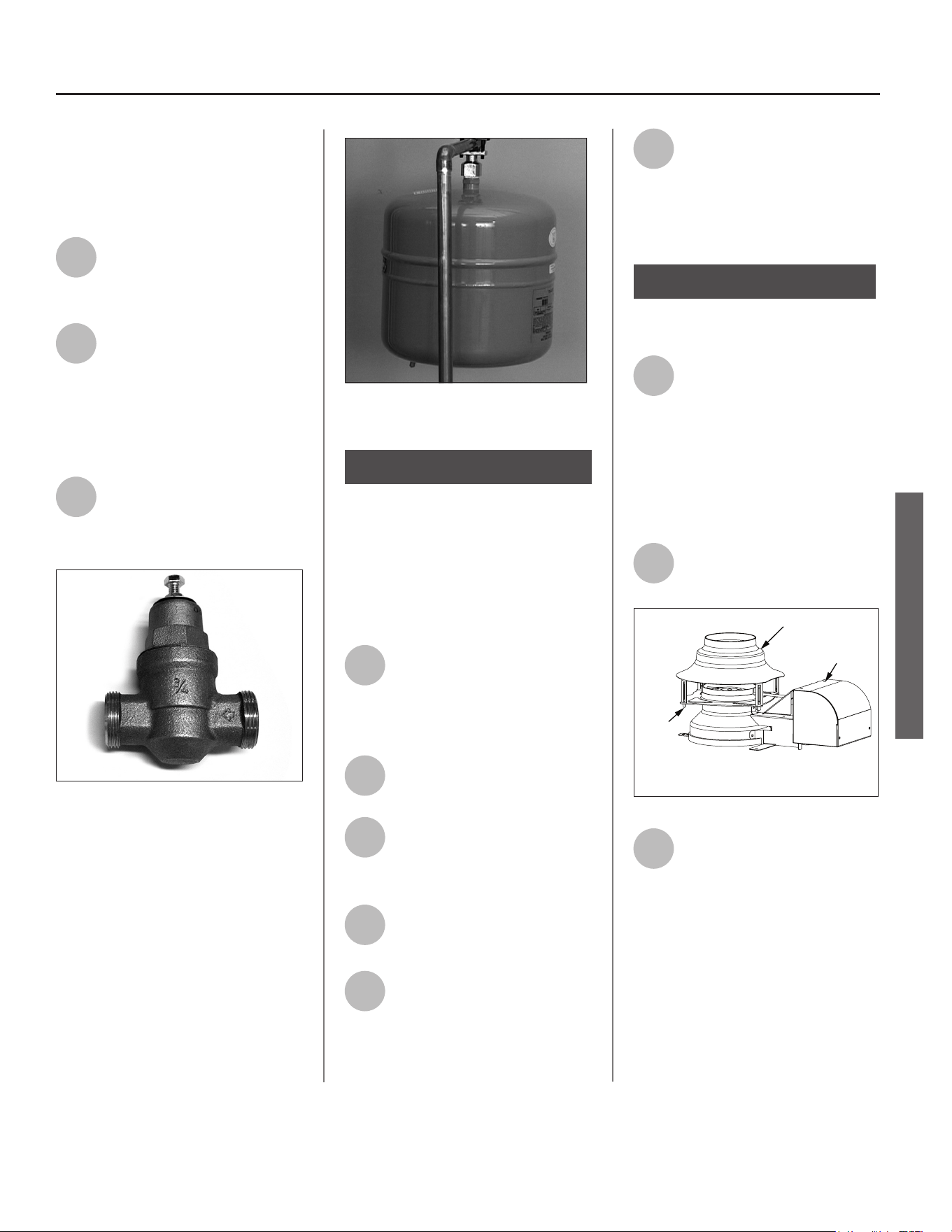
1
Install the new dra hood by
aligning the legs and inserng
them into the slots on the ue
damper’s ange. (See Figure 29.) Do
not reuse the dra hood from the old
water heater, but rather use the new
one that came with your new water
heater.
2
Secure the dra hood by
bending the leg ps, but do not
alter the dra hood in any way.
Draft Hood
Flue Damper
Draft Hood
Leg Tip*
* Twist or bend the leg tips to secure the draft
hood to the flue damper.
* Damper orientation may vary.
Figure 29 - Install the new draft hood.
3
Aach the home’s exisng vent
pipe to the dra hood outlet
using an approved vent
adapter (not supplied). Read the
Venng secon on page 11. Make
sure your home’s venng system
complies with the instrucons in this
manual and is in good condion.
22 • Residenal Standard Gas Ultra Low Nox Water Heater Use and Care Guide
INSTALLATION
INSTALLATION
Step 11:
Make Gas Connecons
The Gas Water Heater Hook-Up Kit
(available at your local plumbing
supplier) includes a exible gas
connector with compression ngs
to connect the home’s gas line to the
water heater’s gas control valve. Follow
the kit’s installaon instrucons to
aach the exible gas connector.
Figure 30 - Flexible gas line connector.
Once you’ve made the gas connec-
ons, use a small, so-bristled brush
to apply a hand dishwashing soap
and water mixture or children’s soap
bubbles (1 part soap to 15 parts water)
to all connecon points of the gas line
and exible gas connector (if used).
Make sure to generously coat all the
connecons and check for gas leaks
(which will appear as small bubbles).
If any leaks are detected, turn the gas
supply o, ghten the leaking connec-
on and re-check.
BEFORE LIGHTING THE WATER
HEATER...
Make sure all checklist items have
been completed.
Water Heater Locaon
✓ Installaon area free of corrosive
or ammable materials, liquids or
vapors.
✓ Proper clearances from combusble
surfaces maintained and sucient
room to service the water heater.
✓ Not installed directly on a carpeted
oor.
✓ Metal drain pan installed and piped
to an adequate drain.
✓ Water heater not located near an
air moving device (fan, clothes
dryer).
✓ Not in a locaon with large
amounts of lint, dust, etc. (If so,
the air lter or ame arrestor
located on the boom of the water
heater will need to be cleaned
more oen.)
Combuson Air Supply and
Venlaon
✓ Adequate air supply for water
heater and any other nearby gas
appliances.
If the water heater is installed in a
closet or other small, enclosed space
or within the living space of the
house, air supply openings needed.
✓ Are the openings of sucient size?
✓ Ductwork is the same cross-sec-
onal area as the openings?
✓ Outside air openings are preferred
and may be required in ghtly built
homes.
Vent Pipe System
✓ New dra hood, properly installed.
✓ Vent pipe securely fastened to
dra hood with screws and sup-
ported properly.
✓ Vent pipe made of approved mate-
rial and either 3” or 4” in diameter.
✓ Vent system installed according
to local and state codes or, in the
absence of local and state codes,
the “Naonal Fuel Gas Code”, ANSI
Z223.1(NFPA 54)-current edion.
✓ Check exisng vent system for rust,
restricons/obstrucons.
Water System Piping
✓ Temperature and pressure relief
valve properly installed with a
discharge line run to an adequate
drain and protected from freezing.
✓ Water pipes free of leaks.
✓ Water heater completely lled with
water.
✓ Thermal Expansion Tank installed
✓ Water Pressure Reducing Valve
installed and adjusted to 50-60 psi.
✓ Thermostac Mixing Valves in-
stalled at each point-of-use.
Gas Supply and Piping
✓ Gas type is the same as that listed
on the water heater’s data plate.
✓ Gas line equipped with shut-o
valve.
✓ Adequate gas pipe size and ap-
proved gas pipe material.
✓ All gas connecons and ngs leak
checked and any leaks corrected.
Residenal Standard Gas Ultra Low Nox Water Heater Use and Care Guide • 23
OPERATION
OPERATION
Lighng Instrucons
WARNING! Explosion Hazard –
Replace viewport if glass is missing or
damaged. Failure to do so can result
in death, explosion or re.
Read and understand these direcons
thoroughly before aempng to
put the water heater into operaon.
Make sure the viewport is not missing
or damaged. Make sure the tank is
completely lled with water before
lighng the pilot. Check the data plate
near the gas control valve to ensure the
correct gas type. Do not use this water
heater with any gas other than the one
listed on the data plate. If you have any
quesons or doubts, consult your gas
supplier or gas ulity company.
NOTICE! A newly installed water heater
will have air in the gas line. It may take
several lighng aempts to clear all the
air from the gas line and light the pilot.
Follow these steps to light the pilot:
1
Make sure the manual gas
valve for the water heater’s
supply line is ON.
Figure 31 - Gas valve in “on” position
2
Plug the water heater into a
grounded 120 VAC outlet.
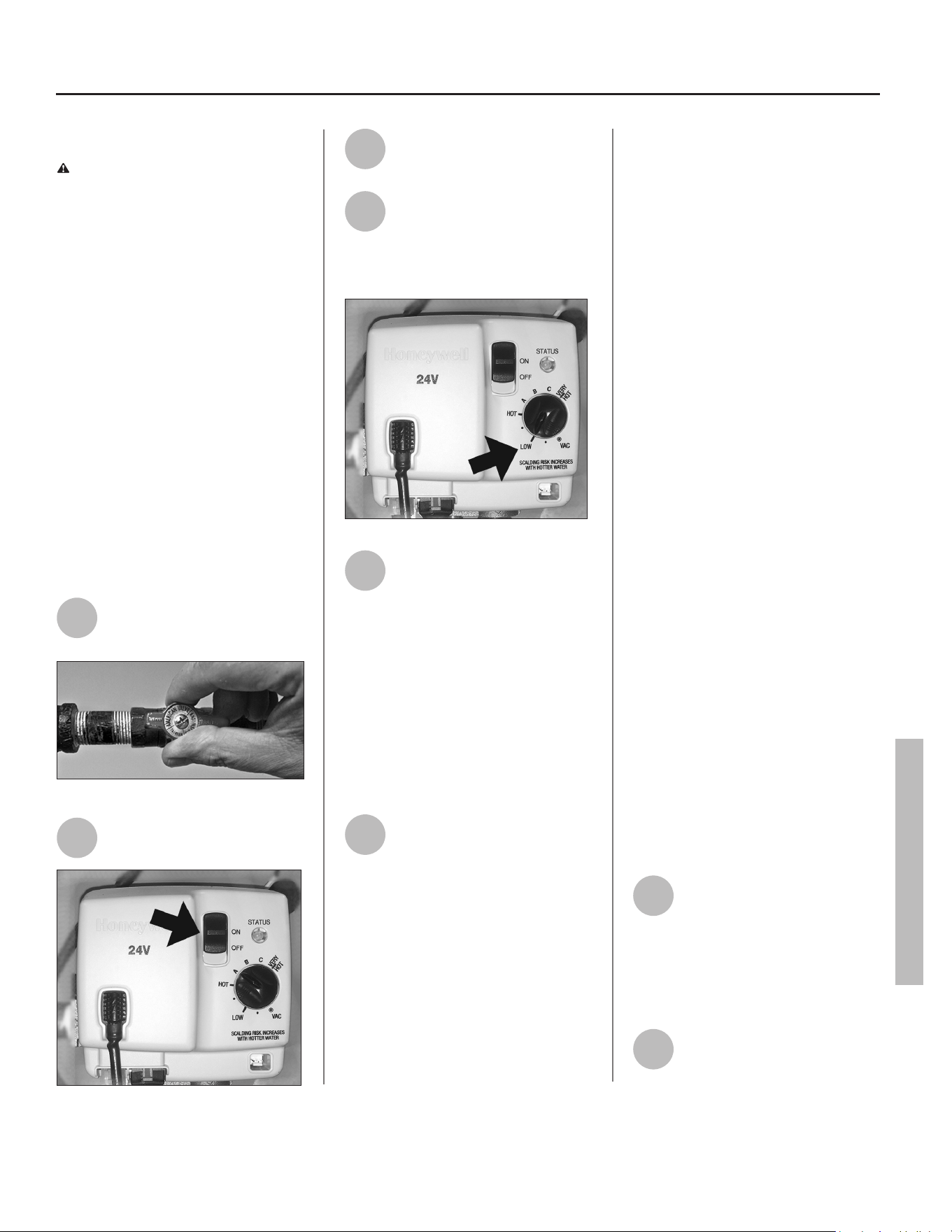
Figure 32 - Move switch to ON position.
3
Move the ON/OFF switch on
the gas control valve to the ON
posion (Figure 32).
4
Turn the gas control valve to
the LOW temperature seng
(Figure 33). The water heater
will light automacally. Do not try to
light the pilot by hand.
Figure 33 - Set knob to LOW setting.
5
When the pilot is lit, the status
light will blink a heartbeat
(bright, dim, bright, dim, etc.).
Adjust the gas control knob to the HOT
seng.
If you receive a ash code (six ashes
followed by a single ash):
A.) Turn the power switch on the gas
valve to the OFF posion. B.) Unplug
the water heater from the wall outlet.
C.) Wait 10 minutes.
D.) Repeat steps 1 through 4.
6
Follow these steps if the Status
Light does not start ashing a
“heartbeat” aer three lighng
aempts: A.) Turn o gas to the water
heater at the manual shut-o valve.
B.) Move the gas valve’s ON/OFF switch
to the OFF posion.
C.) Refer to “Troubleshoong-No Hot
Water” on page 25.
• When a gas water heater is first lit
and the tank is cold, condensation
often forms inside the water heater.
You may hear drips or a sizzling sound
when the water heater is first lit, or
you may see a small puddle on the
floor. Condensation is not a leak and
will go away once the tank reaches
normal operating temperature.
• The air lter at the boom of the water
heater must be cleaned from me to
me. See the Maintenance secon for
steps on cleaning the air lter. If the air
lter is not cleaned as needed, an LDO
fault code may occur. (LDO faults are
diagnosed on page 32.)
Shut down Instrucons
Move the ON/OFF switch on the gas
control valve to the OFF posion. The
status light will stop blinking and stay on
for a short me aer the water heater is
turned o.
Emergency Shut down
Should overheang occur or the gas sup-
ply fail to shut o, follow these steps:
A.) Turn o gas to the water heater at
the manual shut-o valve.
B.) Move the gas valve’s ON/OFF switch
to the OFF posion.
C.) Turn o all electric power to the
water heater. (Unplug it from the 120
VAC outlet.)
Checking the Vent
System and Air Supply
Once the water heater is lit and the gas
control knob is set to the desired temper-
ature, the burner will light (if the tank is
cold). Perform an air supply and vent test
to make sure the unit is venng properly
and the air supply is adequate:
1
The main burner must be on
for this test. With a newly
installed water heater full of
cold water, turning the temperature
control knob to HOT should cause the
main burner to come on. You can view
the burner through the sight glass at
the base of the water heater.
2
Close all windows and doors
and turn on all gas appliances
and air-moving devices (range
hoods, bathroom exhaust fans, ceiling
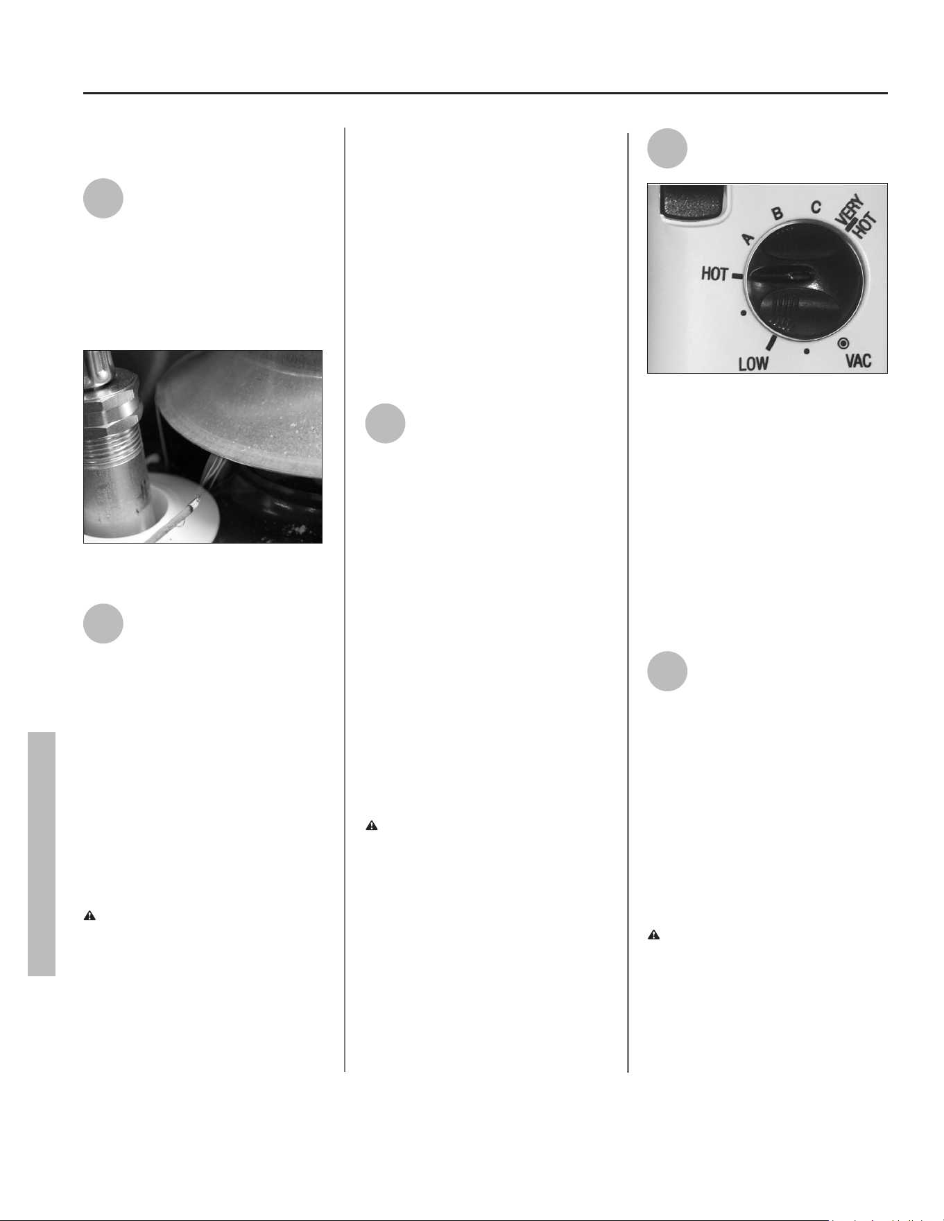
24 • Residenal Standard Gas Ultra Low Nox Water Heater Use and Care Guide
OPERATION
fans, etc.) in your home. Also, close any
replace dampers.
3
Allow the water heater’s main
burner to operate for ve
minutes. Pass a newly exn-
guished match approximately one inch
from the dra hood’s relief opening.
Smoke from the match should be
steadily drawn into the opening indicat-
ing the water heater is geng adequate
air and the vent system is working.
Figure 34 - Test the air supply and vent to make
sure the water heater has adequate air and is
venting properly.
4
If the main burner has been
operang for ve minutes but
the match smoke dris around
or is blown away from the opening, a.)
turn o gas to the water heater at the
manual shut-o valve, b.) turn the gas
valve switch to the OFF posion, then c.)
unplug the water heater from the power
outlet. Inspect the vent system and
repair if necessary. In many cases, failure
to pass the air supply and vent test
indicates the water heater is not geng
enough air or there is a problem with
the vent system. It may be necessary to
increase the air supply by geng air
from outside (see page 7).
WARNING! Burn Hazard. Do not
touch the vent, doing so can cause
burns. If the dra hood does not draw
in smoke from a match aer ve
minutes of main burner operaon,
shut the gas supply o, and do not
operate the water heater unl the vent
system and air supply have been
checked by a qualied person and
repaired if necessary. Connuing to
operate the water heater in this
condion could lead to serious injury
or death from carbon monoxide
poisoning.
Temperature Control
System
Adjusng the Temperature
With the installaon steps completed,
you may adjust the water heater’s tem-
perature seng if desired.
1
Set the gas valve to the desired
temperature. The “HOT”
seng sets the water tem-
perature to approximately 120°F,
reducing the risk of scald injury. You
may wish to set a higher temperature to
provide hot water for automac
dishwashers or laundry machines, to
provide more hot water capacity, and to
reduce bacterial growth. Higher tank
temperatures (140° F) kill bacteria that
cause a condion known as “smelly
water” and can reduce the levels of
bacteria that cause water-borne
diseases.
Water usage paerns, as well as heat
from sources such as solar collectors,
ambient air, and the pilot light can
result in temperatures higher than the
thermostat set-point.
WARNING! Higher temperatures
increase the risk of scalding, but even at
120°F, hot water can scald (see Table 1).
Install Thermostac Mixing Valve(s) at
each point-of-use to reduce the risk of
scalding.
2
To adjust the water heater’s
thermostat:
Figure 35 - Adjust the gas control knob to “HOT”.
Turn the gas control knob on the gas
control valve to the desired seng.
• VAC 55°F
• LOW 91°F
• HOT 120°F
• A 130°F
• B 140°F
• C 150°F
• VERY HOT 155°F
NOTICE: The temperatures above are
approximates. The actual temperature
of the heated water may vary.
3
Wait for the water to heat up.
If you have no hot water aer
two hours, refer to the
Troubleshoong Secon ( page 25 ).
NOTICE: If the tank is full of cold water,
condensaon may form inside the
water heater. This condensaon may
drop on the burner causing a sizzling
sound. In some cases, you may see a
small puddle on the oor. Condensa-
on is normal and should go away once
the tank reaches its normal operang
procedure.
WARNING! If you have increased
the temperature seng and the
Thermostac Mixing Valves are not set
properly (or not installed) you could
scald yourself while checking the
temperature.
OPERATION
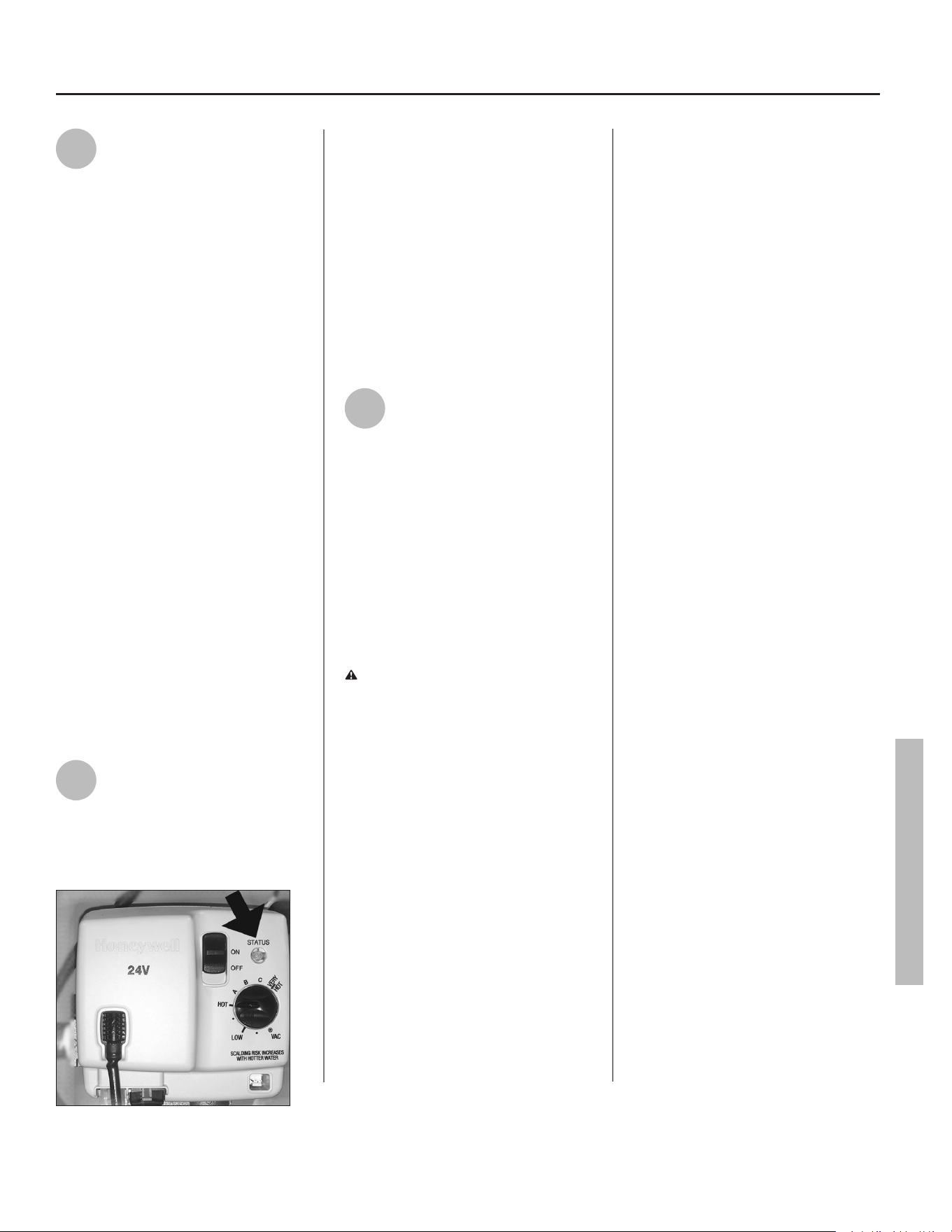
Residenal Standard Gas Ultra Low Nox Water Heater Use and Care Guide • 25
TROUBLESHOOTING
TROUBLESHOOTING
4
Check water temperature at
several points of use in your
home (for example, bathtub
faucet, shower, or lavatory sink) and
adjust the Thermostac Mixing Valves as
needed. If you aren’t sure how to adjust
the Thermostac Mixing Valve sengs,
or aren’t sure if you have Thermostac
Mixing Valves, contact a qualied
person.
Operang Modes
The gas control valve has two dier-
ent operang modes: Standard and
Vacaon. The Standard mode allows
you to adjust the water temperature
to your desired seng. The Vacaon
(VAC) mode sets the thermostat at
approximately 55°F and is recom-
mended when not using hot water for
an extended period of me. The VAC
seng also reduces energy losses and
keeps the tank from freezing during
cold weather but can cause a Hydrogen
gas build up. See cauon on page 6.
No Hot Water
Use the following step-by-step plan
as a guide to help determine why you
have no hot water:
1
Check the Status Light
The Status Light on the gas
control valve ashes once every four
seconds when there are no problems
and there is no call for heat.
Figure 36 - Status light.
If the Status Light is ashing once ev-
ery four seconds and you have no hot
water, make sure the gas control knob
is set to HOT.
If the Status Light ashes a dierent
paern than is described above, refer
to “GAS CONTROL VALVE / THERMO-
STAT - STATUS LIGHT CODETrouble-
shooting Flowchart (Overview)” on
page 27.
If the Status Light is not ashing, go to
step 2.
2
Status Light is Not
Flashing
If the status light on the gas control valve
does not ash, the system may be locked
out. Refer to “LDO Status Light Trouble-
shooting Flowchart” on page 32. Be
sure to read the notes at the top of
that flowchart.
Insucient Hot Water
or Slow Hot Water
Recovery
WARNING! Because of the increased
risk from scalding, if you set the water
heater’s gas control knob higher than
120°F, install Thermostac Mixing
Valves at each point-of-use. Due to the
increased risk of scalding, do not set the
temperature of the Thermostac
Mixing Valves above 120°F.
If the hot water is simply not warm
enough, there are several possible
causes:
• Faulty Thermostac Mixing Valve
in a faucet or shower control
(check other faucets in the house
for hot water).
• Water heater’s capacity too small
(or usage too high).
• Reversed plumbing connecons
or melted dip tube (usually found
soon aer new installaon).
• Plumbing leak.
• Sediment or lime build up in the
boom of the tank.
Thermostac Mixing Valves. If the
hot water is simply not warm enough,
make sure the faucet you are checking
doesn’t have a defecve Thermostac
Mixing Valve. Many shower controls
now have built-in mixing valves. If
these devices fail, they can reduce the
amount of hot water the shower or
faucet delivers even though there is
plenty of hot water in the tank. Always
check the water temperature at several
faucets to make sure the problem is not
in a faucet or shower control.
Undersized Water Heater. If your water
heater runs out of hot water quickly, it
may be too small for your needs. If the
water heater is old, consider replacing it
with a larger model. If the water heater
is in good condion, you may be able
to meet your family’s hot water needs
with the exisng water heater by install-
ing Thermostac Mixing Valves at each
point-of-use and then turning the gas
control knob to a higher seng.
You can also reduce your home’s hot
water needs by washing clothes in cold
water, installing ow restrictors on
shower heads, repairing leaky faucets,
and taking other conservaon steps.
Reversed Connecons or Melted Dip
Tube. Check the hot and cold water
connecons and make sure your
home’s hot water pipe is connected
to the hot water outlet on the water
heater. Usually, reversed connecons
are found soon aer the installaon
of a new unit. If copper pipes were
soldered while they were aached to
the water heater, the dip tube may
have melted. The dip tube is a long,
plasc tube inside the tank aached to
the cold water inlet. If the dip tube has
melted, it can be replaced by removing
the cold water inlet connecon, re-
moving the old dip tube and installing
a new one.
26 • Residenal Standard Gas Ultra Low Nox Water Heater Use and Care Guide
TROUBLESHOOTING
TROUBLESHOOTING
Plumbing Leak. Even a small leak
in the hot water side of the home’s
plumbing system can make it appear
that the water heater is producing
lile to no hot water. In this case, the
burner will be on all or almost all the
me, yet you will have very lile hot
water. Locate and repair the leak.
Sediment or Lime in Tank. With an ex-
isng water heater, if you have some
hot water but not as much as you’re
used to, there may be a build up of
sediment or lime on the boom of the
tank. Sediment or lime build up can
reduce the eciency of your water
heater. Heavy deposits can damage
the water heater. See the Mainte-
nance secon for steps on draining
and ushing the water heater.
Temperature Too High
Adjust the thermostat on the water
heater to a lower seng. Install or
adjust Thermostac Mixing Valves
for each point-of-use (see the valve
manufacturer’s instrucons).
Low Water Pressure
Check both the cold and hot water
at a sink to determine if the lower
pressure is only on the hot water side.
If both hot and cold faucets have low
pressure, call your local water ulity.
If the low pressure is only on the hot
water side, the primary causes are:
• Melted heat traps or dip tube. Sol-
dering copper pipes while they are
connected to the water heater can
melt the heat traps inside the hot
and cold water connecons or the
dip tube (cold water side). Melted
heat traps or a melted dip tube
can restrict the ow of hot water.
If that’s the case, replace the heat
traps or dip tube.
• Parally closed supply valve. Open
the water heater’s supply valve fully.
Drips from T&P Relief
Valve Discharge Pipe
A small amount of water dripping
from the Temperature and Pressure
(T&P) Relief Valve usually means the
home’s water pressure is too high
and/or you need a Thermal Expan-
sion Tank. See Step 1 in the Installa-
on secon of this manual for more
informaon.
A large amount of hot water coming
from the T&P discharge pipe may be
due to the tank overheang. If the
T&P relief valve is discharging large
amounts of very hot water, turn the
gas supply valve o and call a quali-
ed person.
WARNING! Do not cap or plug the
T&P Relief Valve or discharge pipe,
and do not operate the water heater
without a funconing T&P Relief
Valve—this could cause an explosion.
Water Pressure too High. High water
pressure can cause the T&P Relief
Valve to drip. Install a Pressure Re-
ducing Valve (PRV) on the main cold
water supply line. Adjust the PRV to
between 50 and 60 psi.
Thermal Expansion Tank. Install a
Thermal Expansion Tank. If a Thermal
Expansion Tank is already installed
and the T&P Relief Valve discharge
pipe drips, the home’s water pressure
may be too high or the Thermal Ex-
pansion Tank may be defecve. Refer
to the instrucons that came with
the Thermal Expansion Tank for more
informaon.
Debris. In rare cases, debris can sck
inside the T&P Relief Valve prevenng
the valve from sealing fully. In that
case, the T&P Relief Valve discharge
pipe will drip. You may be able to
clear debris from the T&P Relief Valve
by manually operang the valve,
allowing small quanes of water to
ush out the debris. See the label on
the T&P Relief Valve for instrucons.
WARNING! When manually
operang the temperature-pressure
relief valve, make sure that no one is
in front of or around the discharge
outlet. The water may be extremely
hot and could cause severe burns.
Also ensure that the water discharge
will not cause property damage.
If the water pressure is between 50
and 60 psi, a Thermal Expansion Tank
is installed and properly pressurized,
and the valve has been cleared of any
debris, and it sll drips, the valve may
be broken—have a qualied person
replace the T&P Relief Valve.
Water Odor
Harmless bacteria normally present in
tap water can mulply in water heat-
ers and give o a “roen egg” smell.
Although eliminang the bacteria that
causes “smelly water” is the only sure
treatment, in some cases, the stan-
dard anode rod that came with your
water heater can be replaced with a
special zinc anode rod which may help
reduce or eliminate the odor. Contact
a qualied person.
NOTICE: To protect the tank, an anode
rod must be installed in the water
heater at all mes or the warranty is
void.
In cases where the “roen egg” smell
is very strong, you could increase the
tank temperature to 140°F in order to
reduce bacterial growth in the tank.
WARNING! Because higher
temperatures increase the risk of
scalding, if you set the thermostat(s)
higher than 120°F, Thermostac
Mixing Valves at each point-of-use
are parcularly important.
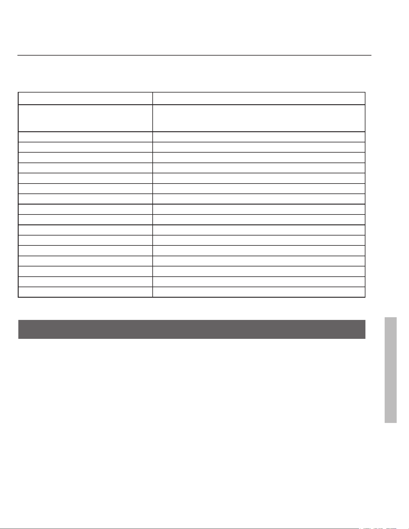
Residenal Standard Gas Ultra Low Nox Water Heater Use and Care Guide • 27
TROUBLESHOOTING
GAS CONTROL VALVE / THERMOSTAT - STATUS LIGHT CODE-
TROUBLESHOOTING FLOWCHART (OVERVIEW)
LED FLASH SEQUENCE CONTROL STATUS
No Flash Lock out. (Check the status light on the LDO module and refer to the LDO
Status Light Troubleshooting Flowchart on page 32. The location of the
LDO module is shown on page 2.)
Short ash once every four second IDLE (No call for heat, no fault condions)
“Heartbeat”, alternates bright/dim Call for Heat (No fault condions)
One Flash, three second pause Low Flame Signal (control connues to operate)
Two Flash, three second pause End Switch Failed Closed
Three Flash, three second pause End Switch Failed Open
Four Flash, three second pause ECO Limit Lockout (Overheat Failure)
Five Flash, three second pause Flame Out of Sequence
Six-One Flash, three second pause So Lockout* - Retry Limit - Failed TFI (Trial for Ignion)
Six-Two Flash, three second pause So Lockout* - Recycle Limit - Flame Lost - END Switch Fails
Six-Three Flash, three second pause So Lockout* - Recycle Limit - Flame Lost
Six-Four Flash, three second pause So Lockout* - Flame out of Sequence Sensed
Seven Flash, three second pause Flammable Vapor Sensor (FVS) Lockout
Eight-One Flash, three second pause Flammable Vapor Sensor (FVS) Fault Detected
Eight-Two Flash, three second pause Temperature Sensor Fault Detected (No Light)
Eight-Three Flash, three second pause Electronic Fault Detected
Eight-Four Flash, three second pause Gas Control Valve/Thermostat Fault Detected
EXAMPLE: An “Eight-Four Flash” will show eight flashes, then four flashes, followed by a three second pause.
The pattern will then repeat.
* Soft Lockout - 20 minute wait before returning to normal mode.
NOTICE:
• These codes apply to the gas control valve. The locaon of the gas control valve is shown on page 2.
• Refer to the following pages for detailed troubleshoong procedures.
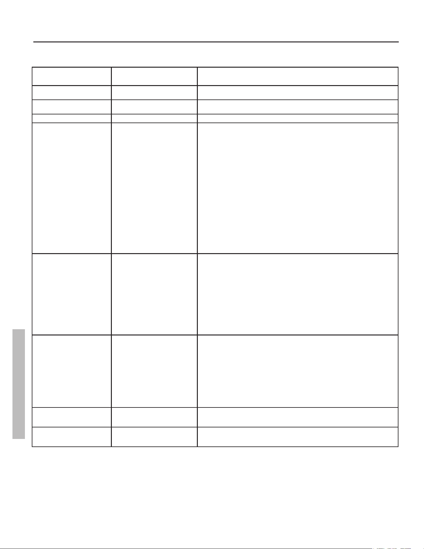
28 • Residenal Standard Gas Ultra Low Nox Water Heater Use and Care Guide
TROUBLESHOOTING
STATUS LIGHT TROUBLESHOOTING FLOWCHART
LED FLASH SEQUENCE GAS CONTROL
VALVE STATUS
CORRECTIVE ACTION
No Flash Lock out Check the status light on the LDO module and refer to the LDO Status Light Troubleshooting
Flowchart on page 30. The location of the LDO module is shown on page 2.
Short flash once every four second IDLE (No call for heat, no fault
conditions)
“Heartbeat”, alternates bright/dim Call for Heat (No fault conditions)
One Flash, three second pause Low Flame Signal
(control continues to operate)
Turn the power switch on the gas control valve to the “OFF” position and unplug the power cord
from the power outlet.
1. Check the incoming gas line pressure to ensure adequate supply to the water heater. If
incoming gas supply pressure is adequate, proceed to step 2.
2. Check all wiring connections and ensure all harness and wire connections are seated
firmly and provide proper electrical contact. If no connection problems are found, proceed
to step 3. Firmly seat any loose connections found. If any connections are found to be
damaged, consult the replacement parts list for the appropriate replacement. After any
connection problems are fixed, restart the water heater by following the lighting instructions
on page 23. If the problem persists, proceed to step 3.
3. Check the condition of the base ring filter and flame arrestor. If they are clogged, follow
the instructions for cleaning on page 36. If parts are not clogged, proceed to step
4. After cleaning, follow the instructions for lighting on page 23. If problem persists,
proceed to step 4.
4. Follow the instructions on page 35 to remove the burner assembly. Once the burner
assembly has been removed, inspect the manifold tube and burner for any obstructions. If
any clogs or obstructions are present, clear them. Inspect the pilot assembly’s electrode/
flame sense rod for corrosion buildup, degradation, or damage. If there is evidence of any
damage to the electrode/flame sense rod, replace the igniter/pilot assembly. Follow the
directions on page 35 to re-install the burner assembly into the combustion chamber.
Follow the instructions for lighting on page 23. If the problem persists, contact a certified
service representative.
Two Flash, three second pause End Switch Failed Closed Look at the top of water heater to see if the damper is open (Figure 29, page 21). If the
damper is open, ensure there is no obstruction that would prevent the damper from closing. If
there are any obstructions, turn the power switch on the gas valve to the “OFF” position, then
remove the obstruction. If the damper closes, turn the power switch on the gas valve to the
“ON” position. If there are no obstructions present, turn the power switch on the gas valve to the
“OFF” position. Observe the damper to see if the damper closes. If the damper does not close,
unplug the power cord from the power outlet and proceed to step 1. If the damper closes turn
the power switch on the gas valve to the “ON” position.
1. Check all wiring connections to ensure all harness and wire connections are seated firmly
and provide proper electrical contact. If no connection problems are found, replace the
damper. Firmly seat any loose connections found. If any connections are found to be
damaged, consult the replacement parts list on for the appropriate replacement. After any
connection problems are fixed, restart the water heater by following the lighting instructions
on page 23. If the problem persists, replace the damper.
Three Flash, three second pause End Switch Failed Open
Turn the power switch on the gas control valve to the “OFF” position and unplug the power cord
from the power outlet.
1. Follow the lighting instructions on page 24. Observe the damper during initial startup. If
there is a call for heat and the damper opens, allow the unit to continue to perform and
monitor any change in status. If there is a call for heat and the damper does not open,
procede to step 2.
2. Check all wiring connections to insure all harness and wire connections are seated firmly
and provide proper electrical contact.If no connection problems are found replace the
damper.Firmly seat any loose connections found. If any connections are found to be
damaged, consult the replacement parts list on page 39. After any connection problems
are fixed, restart the water heater by following the lighting instructions on page 24. If the
problem persists, replace the damper.
Four Flash, three second pause ECO Limit Lockout 1. Turn the power switch on the gas control valve to the “OFF” position, wait 10-20 seconds,
then turn the power switch on the gas control valve to the “ON” position. If the problem
persists, replace the gas control valve. (See page 34.)
Five Flash, three second pause Flame Out of Sequence 1. Turn the power switch on the gas control valve to the “OFF” position. Wait 10 minutes,
then follow the lighting instructions on page 23. If the problem persists, replace the gas
control valve. (See page 34.)
GasControlValve/Thermostat-StatusLightCode
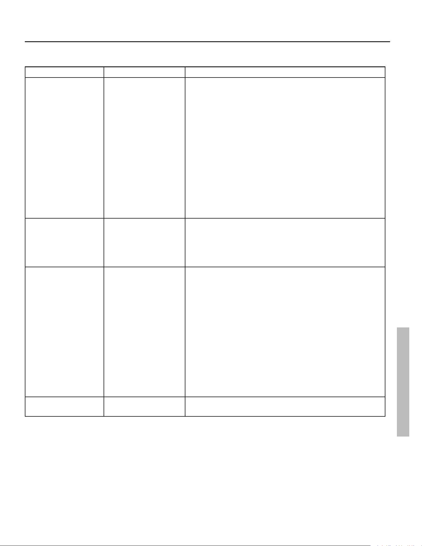
Residenal Standard Gas Ultra Low Nox Water Heater Use and Care Guide • 29
TROUBLESHOOTING
STATUS LIGHT TROUBLESHOOTING FLOWCHART (CONTINUED)
LED FLASH SEQUENCE CONTROL STATUS CORRECTIVE ACTION
Six-One Flash, three second pause Soft Lockout* - Retry Limit -
Failed TFI (Trial for Ignition)
Turn the power switch on the gas valve to the OFF position. Unplug the water heater from the
wall outlet. Plug the power cord back in, then follow the lighting instructions on page 23. If that
does not work, turn the power switch on the gas control valve to the “OFF” position, unplug the
power cord from the power outlet, then follow the steps below.
1. Check the incoming gas line pressure to ensure adequate supply to the water heater. If
incoming gas supply pressure is adequate, proceed to step 2.
2. Check all wiring connections and ensure all harness and wire connections are seated
firmly and provide proper electrical contact. If no connection problems are found, proceed
to step 3. Firmly seat any loose connections found. If any connections are found to be
damaged, consult the replacement parts list for the appropriate replacement. After any
connection problems are fixed, restart the water heater by following the lighting instructions
on page 23. If the problem persists, proceed to step 3.
3. Check the condition of the base ring filter and flame arrestor. If they are clogged, follow
the instructions for cleaning on page 36. If parts are not clogged, proceed to step
4. After cleaning, follow the instructions for lighting on page 23. If problem persists,
proceed to step 4.
4. Follow the instructions on page 35 to remove the burner assembly. Once the burner
assembly has been removed, inspect the manifold tube and burner for any obstructions. If
any clogs or obstructions are present, clear them. Inspect the pilot assembly’s electrode/
flame sense rod for corrosion buildup, degradation, or damage. If there is evidence of any
damage to the electrode/flame sense rod, replace the igniter/pilot assembly. Follow the
directions on page 35 to re-install the burner assembly into the combustion chamber.
Follow the instructions for lighting on page 23. If the problem persists, contact a
qualified service representative.
Six-Two Flash, three second pause Soft Lockout* - Recycle Limit - Flame
Lost - END Switch Fails
Turn the power switch on the gas control valve to the “OFF” position and unplug the power cord
from the power outlet.
1. Check all wiring connections to ensure all harness and wire connections are seated firmly
and provide proper electrical contact. If no connection problems are found, replace the
damper. Firmly seat any loose connections found. If any connections are found to be
damaged, consult the replacement parts list for the appropriate replacement. After any
connection problems are fixed, restart the water heater by following the lighting instructions
on page 23. If the problem persists, replace the damper.
Six-Three Flash, three second
pause
Soft Lockout* - Recycle Limit - Flame
Lost
* Soft Lockout - 20 minute wait before
returning to normal mode.
Turn the power switch on the gas control valve to the “OFF” position and unplug the power cord
from the power outlet.
1. Check the incoming gas line pressure to ensure adequate supply to the water heater. If
incoming gas supply pressure is adequate, proceed to step 2.
2. Check all wiring connections and ensure all harness and wire connections are seated
firmly and provide proper electrical contact. If no connection problems are found, proceed
to step 3. Firmly seat any loose connections found. If any connections are found to be
damaged, consult the replacement parts list for the appropriate replacement. After any
connection problems are fixed, restart the water heater by following the lighting instructions
on page 23. If the problem persists, proceed to step 3.
3. Check condition of the base ring filter and flame arrestor. If they are clogged, follow the
instructions for cleaning on page 36. If the parts are not clogged, proceed to step
4. After cleaning, follow instructions for lighting on page 23. If the problem persists,
proceed to step 4.
4. Follow the instructions on page 35 to remove the burner assembly. Once the burner
assembly has been removed, inspect the manifold tube and burner for any obstructions. If
any clogs or obstructions are present, clear them. Inspect the pilot assembly’s electrode/
flame sense rod for corrosion buildup, degradation, or damage. If there is evidence of any
damage to the electrode/flame sense rod, replace the igniter/pilot assembly. Follow the
directions on page 35 to re-install the burner assembly into the combustion chamber.
Follow the instructions for lighting on page 23. If the problem persists, contact a
qualified service representative.
Six-Four Flash, three second pause Soft Lockout* - Flame out of
Sequence Sensed
Turn the power switch on the gas control valve to the “OFF” position and unplug the power cord
from the power outlet. Wait 10 minutes, then follow the lighting instructions on page 23. If the
problem persists, replace the gas control valve. (See page 34.)
GasControlValve/Thermostat-StatusLightCode
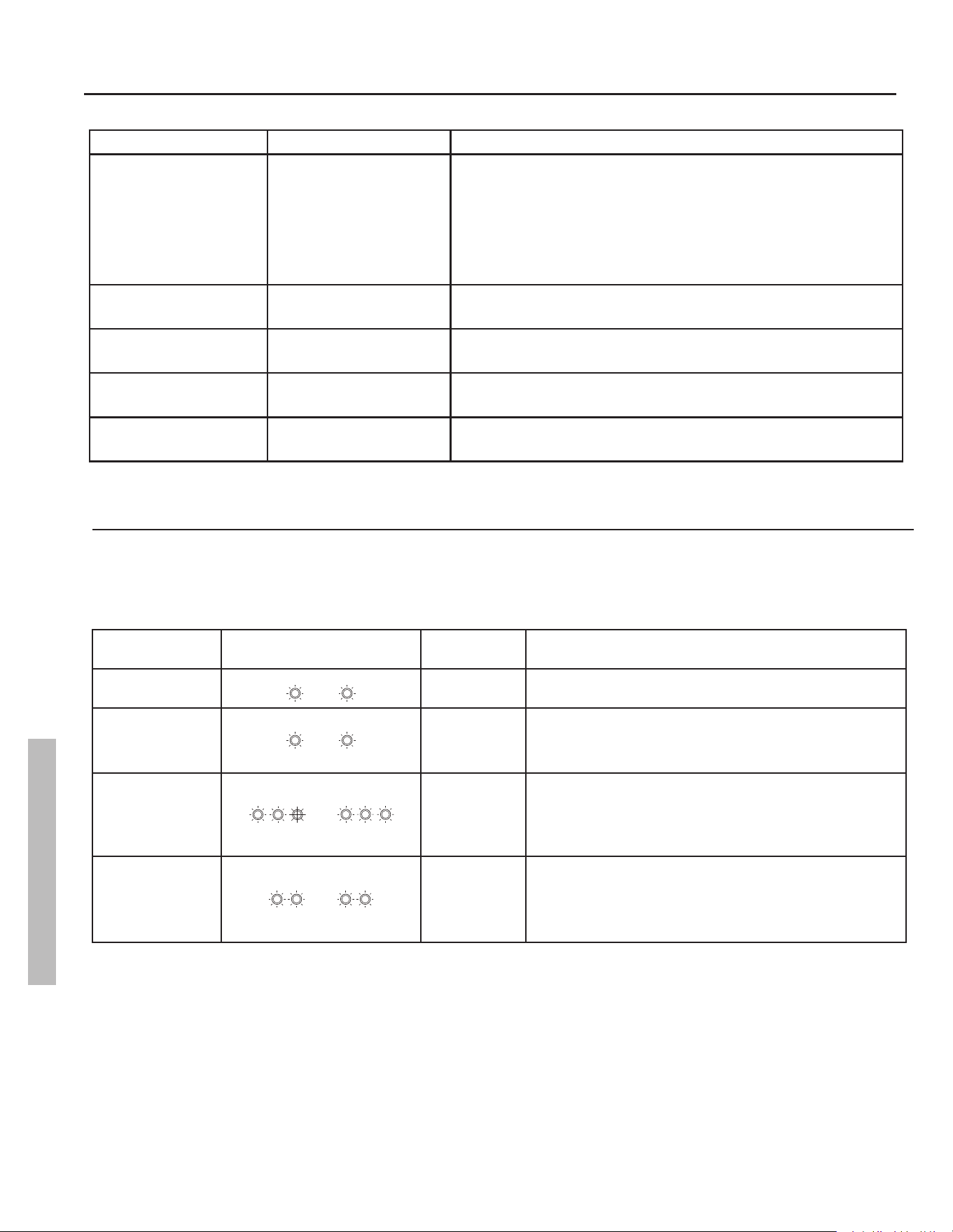
30 • Residenal Standard Gas Ultra Low Nox Water Heater Use and Care Guide
TROUBLESHOOTING
STATUS LIGHT TROUBLESHOOTING FLOWCHART (CONTINUED)
STATUS LIGHT TROUBLESHOOTING FLOWCHART
• These codes apply to the LDO module. See page 2 for the locaon of the LDO module.
• If the status light on the gas control valve is not ashing, check the status light on the LDO module
and refer to the table below.
NOTICE:
Status LDO Status
Gas Control
ValveStatus
CorrectiveAction
Normal Operaon
1 sec.
Heart Beat None Needed
Burner Failure
4 sec.
No Light
• Replace Burner
• Press and hold reset button on LDO module for 3 sec-
onds to clear the fault code.
Lint Build-Up
Detected
1 sec.
No Light
• Remove Lint and Dust Build-up.
• Ensure gas supply pressure is correct.
• Requires main power to be cycled in order to clear fault
code.
Chamber Sensor
Failure
4 sec.
No Light
• Ensure sensor is connected properly to LDO module.
• Replace Chamber Sensor.
See Figure 50.
• Fault code clears immediately when condition clears.
LED FLASH SEQUENCE CONTROL STATUS CORRECTIVE ACTION
Seven Flash, three second pause Flammable Vapor Sensor (FVS)
Lockout
1. Do not touch any electrical switch, do not use any phone in the building, and do not try to
light any appliance.
2. Smell around the water heater to ensure there are no gas leaks at the gas control valve or
in the supply gas line or for any other type of flammable vapors in the area.
3. Carefully inspect the area surrounding the water heater for any substances such as
gasoline, paint, paint thinners, varnish, or cleaners that could emit flammable vapors.
Remove anything that can potentially emit flammable vapors from the area and store it
properly in a different location.
4. Contact a qualified service representative for inspection and/or replacement of the FV sensor.
Eight-One Flash, three second
pause
Flammable Vapor Sensor (FVS) Fault
Detected
Turn the power switch on the gas control valve to the “OFF” position, wait 10-20 seconds, then
turn the power switch on the gas control valve to the “ON” position. If the problem persists,
replace the gas valve.
Eight-Two Flash, three second
pause
Temperature Sensor Fault Detected Turn the power switch on the gas control valve to the “OFF” position, wait 10-20 seconds, then
turn the power switch on the gas control valve to the “ON” position. If the problem persists,
replace the gas valve.
Eight-Three Flash, three second
pause
Electronic Fault Detected Turn the power switch on the gas control valve to the “OFF” position, wait 10-20 seconds, then
turn the power switch on the gas control valve to the “ON” position. If the problem persists,
replace the gas valve.
Eight-Four Flash, three second
pause
Gas Control Valve/Thermostat Fault
Detected
Turn the power switch on the gas control valve to the “OFF” position, wait 10-20 seconds, then
turn the power switch on the gas control valve to the “ON” position. If the problem persists,
replace the gas valve.
* Soft Lockout - 20 minute wait before returning to normal mode.
GasControlValve/Thermostat-StatusLightCode
LDO Module - Status Light Code
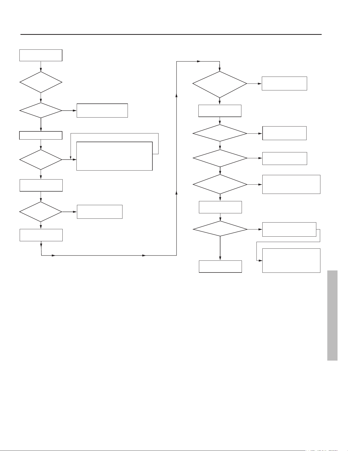
Residenal Standard Gas Ultra Low Nox Water Heater Use and Care Guide • 31
SEQUENCE OF OPERATIONS CHART
TROUBLESHOOTING
Apply Power
to Appliance.
Is Damper
Closed?
Y
Is there a
Call for Heat.
Is Damper
Open?
Will not attempt to light. 2
flash error code.
N
Damper Energizes.
Gas Valve attempts to open damper
for 30 seconds, displays 3 flash error
code, and then waits 2 minutes before
attempting to open damper again.
N
Pilot Valve
Energizes
Does Pilot
Valve Open?
Spark Electrode
is Energized
Is
Pilot Flame
Sensed Within
1.5 min. ?
Main Valve
Energized
Does Main
Valve Open?
Is Main
Flame Sensed?
Is Demand for
Heat Satisfied?
Pilot & Main
Valve De-Energize.
Is Flame
Sensed?
Damper Energizes
and Closes.
Will not light. 8-4 flash
error code.
N
Will not light. 8-4 flash
error code.
N
Will not light. 8-4 flash
error code.
N
Will not light. 8-4 flash
error code.
N
Water heater will continue to
operate normally until
demand is satisfied.
N
Wait for flame lost, 5 flash
error code.
Y
Damper closes, displays 6-4
Flash Error Code, and gas
control valve goes into 20
minute lockout.
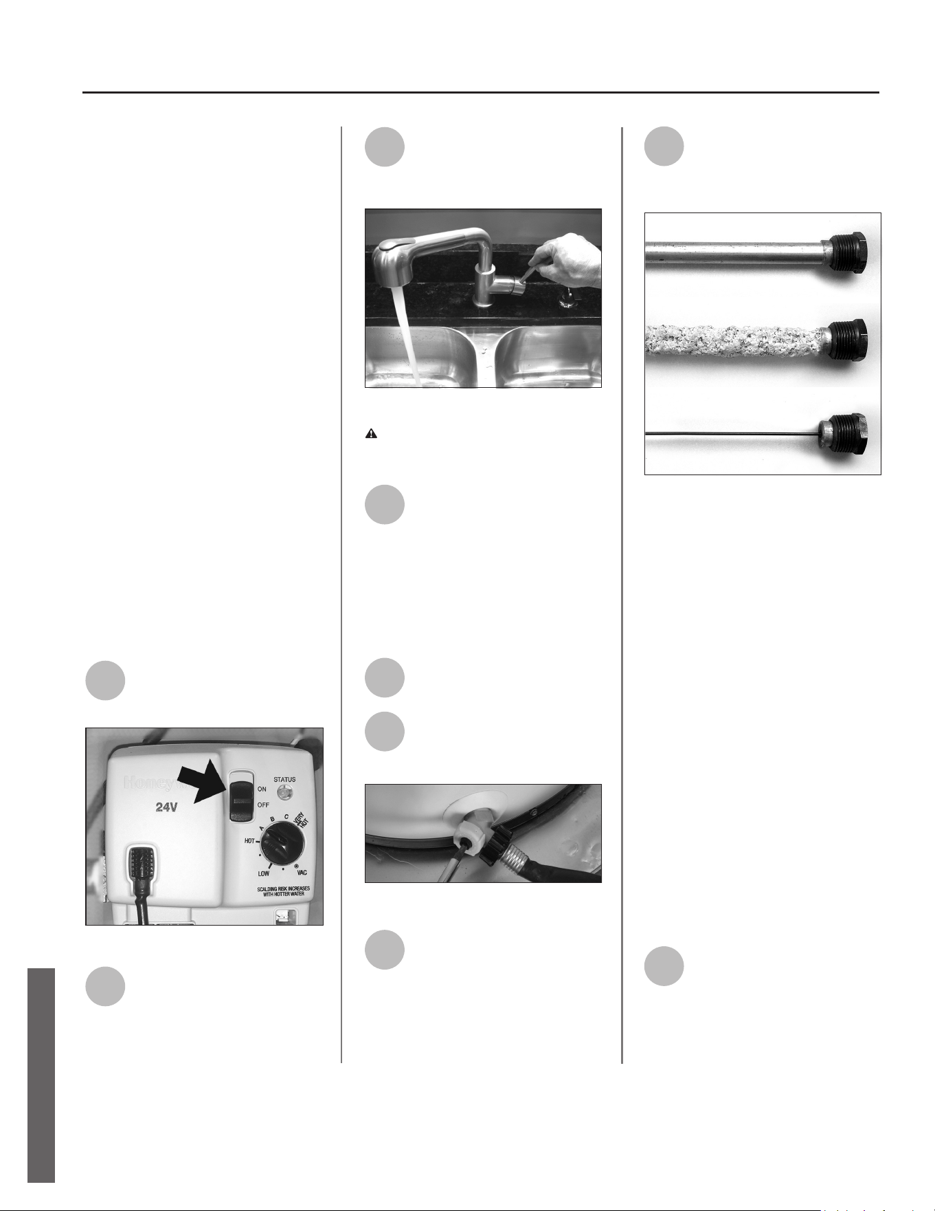
32 • Residenal Standard Gas Ultra Low Nox Water Heater Use and Care Guide
MAINTENANCE
LDO STATUS LIGHT TROUBLESHOOTING FLOWCHART
Roune Maintenance
Roune maintenance will help your
water heater last longer and work bet-
ter. If you can’t perform these roune
maintenance tasks yourself, contact a
qualied person.
Draining and Flushing the
Water Heater
Tap water contains minerals that can
form sediment in the boom of the
tank. The amount of sediment formed
depends on the hardness of your tap
water, the temperature sengs, and
other variables. We recommend drain-
ing and ushing the water heater aer
the rst six months of operaon to de-
termine the amount of sediment build
up. If there is lile sediment, drain and
ush the tank annually. If there is a lot
of sediment, drain and ush the tank
more oen. Draining sediment extends
the life of the water heater.
To Drain and Flush the Tank:
1
Turn the power switch on the
gas control valve to the OFF
posion.
Figure 37 - Turn gas control/temperature knob
OFF.
2
Turn the manual gas valve for
the water heater’s supply line
OFF.
3
Open a hot water faucet and
let the hot water run unl it is
cool (This may take 10
minutes or longer).
Figure 38 - Let the hot water run until it is cool.
WARNING! Be sure the water runs
cool before draining the tank to
reduce the risk of scalding.
4
Connect a garden hose to the
drain valve and place the
other end of the hose in a
drain, outside, or in buckets. Note that
sediment in the boom of the tank
may clog the valve and prevent it from
draining. If you can’t get the tank to
drain, contact a qualied person.
5
Turn the cold water supply
valve OFF.
6
Open the drain valve on the
water heater.
Figure 39 - Draining the water heater.
7
Also open a hot water faucet
to help the water in the tank
drain faster.
8
Remove and inspect the
anode rod and replace if
depleted. The anode rod
requires a 1-1/16” socket.
Figure 40 - Anode rods from new (top) to par-
tially depleted (middle) to fully depleted stage
(bottom).
Anode Rod. The anode rod is a sacri-
cial metal rod that helps avoid corro-
sion and premature failure (leaks) in
the tank. The anode rod is a consum-
able item. Inspect the anode rod aer
the rst six months of operaon when
you drain and ush the tank. Replace
the anode rod if it is substanally worn
out or depleted. Thereaer, inspect the
anode rod annually or more frequently
if needed. If you use a water soener,
your anode rod will deplete faster than
normal. Inspect the anode rod more
frequently, replacing the anode rod if
it is depleted. Obtain a new anode rod
from your local plumbing supplier or
have a qualied person replace it. (An-
ode rods are a consumable item and
are not covered under warranty).
9
If a large amount of sediment
was present when the tank
was drained, ush the tank by
opening the cold water supply valve
and leng the water run unl no more
sediment drains from the tank. Close
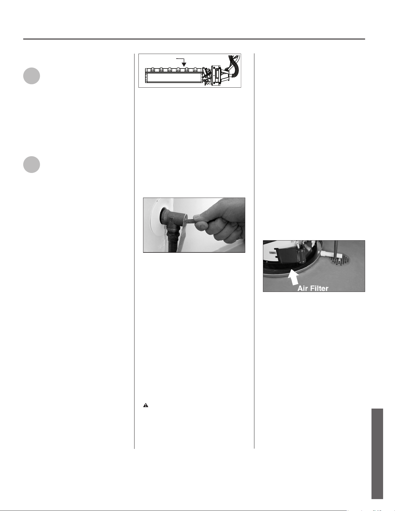
Residenal Standard Gas Ultra Low Nox Water Heater Use and Care Guide • 33
MAINTENANCE
SEQUENCE OF OPERATIONS CHART
the drain valve when you are done.
10
Rell the tank by opening the
cold water supply valve. Make
sure a hot water faucet is open
and the drain valve is closed. Allow a
hot water faucet to run full for at least
three minutes to make sure the tank
has all the air removed and is complete-
ly full of water. Once you are certain the
tank is completely full of water, close
the hot water faucet.
11
Put the water heater back into
operaon by following the
lighng instrucons on page
23. Adjust the gas control knob to
the desired temperature. It may take an
hour or more for the tank of cold water
to heat up.
Visual Inspecon
On an annual basis, visually inspect the
venng and air supply system, piping
systems, main burner, pilot burner, and
the air lter.
Check the water heater for the following:
• Obstrucons, damage, or deterio-
raon in the venng system. Make
sure the venlaon and combus-
on air supplies are not obstruct-
ed. Check the air lter for dust or
other debris and clean if needed.
• Build up of soot and carbon on
the main burner and pilot burner.
The burner may be cleaned with
soap and hot water.
• Inspect the burner ames through
the viewport and compare them
to Figure 41. The ames should
be very small with a blue haze and
small amount of yellow or orange
at the edges. Aer several minutes
of operaon, the burner screen
may glow red. If large ames are
observed at any me, shut-o the
unit and call a qualied person.
Figure 41 - Burner Flames
• Leaking or damaged water and gas
piping.
• Remove any ammable, corrosive
or combusble materials near the
water heater.
If you lack the necessary skills required
to properly perform this visual inspec-
on or if the burner needs to be cleaned,
get help from a qualied person.
T&P Relief Valve Maintenance
Figure 42 - T&P Relief Valve.
Read and follow the operang and an-
nual maintenance instrucons provided
by the manufacturer of the T&P Relief
Valve (yellow label aached to T&P
Relief Valve). Minerals in the water can
form deposits that cause the valve to
sck or create blocked passages, mak-
ing the T&P Relief Valve inoperave.
Follow these guidelines:
• At least annually, operate the T&P
Relief Valve manually to ensure the
waterways are clear and the valve
mechanism moves freely (above).
Before operang the valve manually,
check that it will discharge in a place
for secure disposal.
WARNING! Hot water will be released.
Before operang the T&P relief valve
manually, check that it will discharge in a
safe place. If water does not ow freely
from the end of the discharge pipe, turn
the gas control knob to the OFF posion
and call a qualied person to determine
the cause.
• At least every ve years, have a
qualied person inspect the T&P
Relief Valve and discharge pipe.
Damage caused by corrosive water
condions, mineral deposits, or
other problems can only be de-
termined when a qualied person
removes and inspects the valve
and its components.
A dripping T&P Relief Valve is usually
caused by the home’s water pressure
being too high or the lack of a Thermal
Expansion Tank. If your T&P Relief Valve
drips, see page 26.
A T&P relief valve that has been al-
lowed to drip for an appreciable period
of me should be inspected for mineral
buildup. See T&P relief valve tag for
more informaon.
Inspect and Clean the Air Filter
Figure 43 - Clean air filter periodically.
An air lter is installed around the base
of your water heater. At least annu-
ally, inspect the air lter and check for a
build-up of dust or debris. If it needs to
be cleaned, turn o the water heater and
allow it to cool for ten minutes before
cleaning. Vacuum the lter to remove
any dust or debris. If an oily residue is
present on the lter, wash it in soap and
water, then dry the lter. NOTICE: If you
are unable to inspect or clean the lter,
follow the “Cleaning the Combuson
Chamber and Flame-arrestor” instruc-
ons on page 36.
Correct flame
soft blue
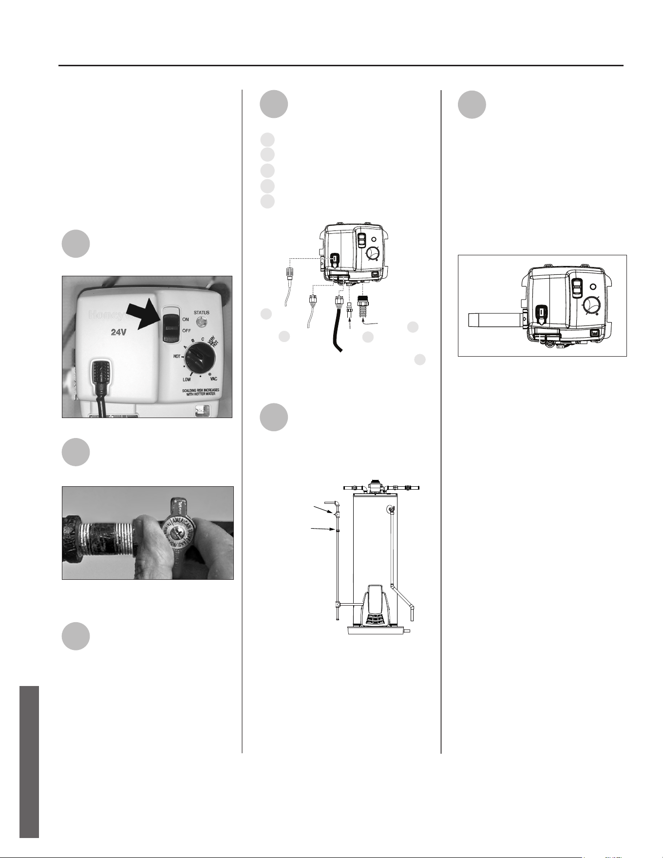
34 • Residenal Standard Gas Ultra Low Nox Water Heater Use and Care Guide
MAINTENANCE
Removing and Replac-
ing the Gas Control
Valve/Thermostat
IMPORTANT: The gas control valve/
thermostat is a standard valve.
Removing the Gas Control Valve/
Thermostat:
1
Turn the gas control valve
switch to the “OFF” posion.
Figure 44 - Turn the gas control valve off.
2
Turn o the gas at the
manual shut-o valve on the
gas supply pipe.
Figure 45 - Gas valve in “off” position.
3
Drain the water heater. Refer
to “Draining and Flushing the
Water Heater” and follow the
procedure. (See page 32.)
4
Disconnect the following
items from the gas control
valve/thermostat:
A
Igniter wire
B
Wiring harness
C
FV sensor wires
D
Pilot tube (7/16” wrench)
E
Manifold tube (3/4” wrench)
Pilot
Tube
Manifold
Tube
FV Sensor
(from bottom of heater)
ON
OFF
STATUS
E
c
D
B
A
Igniter
Wire
Wiring
Harness
(from black
box and hole
in jacket)
A
B
C
•
•
VERY
HOT
HOT
LOW
VAC
Figure 46 - Gas valve connections.
5
Disconnect the ground joint
union in the gas piping.
Disconnect the remaining
pipe from the gas control valve/
thermostat.
GROUND
JOINT
UNION
MANUAL GAS
SHUT-OFF VALVE
Figure 47 - Ground joint union connection.
6
To remove the gas control
valve/thermostat, thread a 4”
secon of gas pipe into the
inlet and use it to turn the gas control
valve/thermostat (counterclockwise).
Do not use pipe wrench or equivalent
to grip body. Damage may result,
causing leaks. Do not insert any sharp
objects into the inlet or outlet connec-
ons. Damage to the gas control valve/
thermostat may result.
ON
OFF
STATUS
A
B
C
•
•
VERY
HOT
HOT
LOW
VAC
Figure 48 - Gas control/valve with 4” section of
threaded gas pipe.
Replacing the Gas Control Valve/
Thermostat:
• Be sure to use approved Teflon®
tape or pipe joint compound on
the gas piping connections and
fitting on the back of the gas con-
trol valve that screws into tank.
• Be sure to remove the pilot fer-
rule nut from the new gas control
valve/thermostat.
Replace the gas control valve/thermo-
stat by reassembling in reverse order.
When replacing the gas control valve/
thermostat, thread a 4” secon of
gas pipe into the inlet and use it to
turn the gas control valve/thermostat
(clockwise). DO NOT OVER TIGHTEN.
Damage may result.
MAINTENANCE
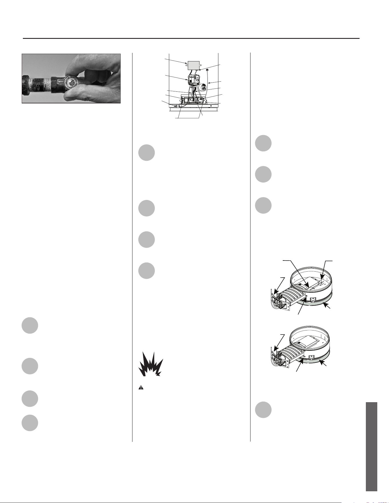
Residenal Standard Gas Ultra Low Nox Water Heater Use and Care Guide • 35
MAINTENANCE
MAINTENANCE
Figure 49 - Gas valve in “on” position.
• Be sure tank is completely filled
with water before lighting and
activating the water heater. Fol-
low the “Lighting Instructions” on
page 23.
• Turn the gas supply on and check
for leaks. Test the water heater
with the main burner on by
brushing on an approved noncor-
rosive leak detection solution.
Bubbles forming indicate a leak.
Correct any leak found.
• If additional information is
required, contact the Service
Department at:
1-800-999-9515.
Removing and Replacing
the Manifold/Burner
Assembly
Removing the Manifold/Burner
Assembly
1
Move the ON/OFF switch on
the gas control valve/thermo-
stat to the “OFF” posion to
turn o the water heater (Figure 44).
2
Turn o the gas to the water
heater at the manual gas
shut-o valve (Figure 45).
3
Remove the outer door.
4
Remove the manifold screws
(1/4” nut driver) securing the
manifold door to the
combuson chamber (Figure 50).
Figure 50 - Front view of water heater with
outer door removed.
5
Go to the gas control valve/
thermostat and disconnect
the pilot tube (7/16” wrench),
igniter wire, and manifold tube (3/4”
wrench). Disconnect the FV sensor and
wiring harness.
Disconnect the temperature
sensor wires from the LDO
module.
7
Grasp the manifold tube and
push down slightly to free the
manifold and pilot tube.
8
Carefully remove the burner
door assembly from the
burner compartment. To
reinstall it, see “Replacing the
Manifold/Burner Assembly”
NOTICE: Be sure not to damage
internal parts.
Replacing the Manifold/Burner
Assembly
Explosion Risk
WARNING! Failure to follow these
instrucons can result in serious injury
or death from explosion, re or
carbon monoxide poisoning.
• Tighten the manifold door screws
securely.
• Remove any berglass between
gasket and combuson chamber.
• Replace viewport if glass is missing
or damaged.
• Replace the manifold component
block if it is missing or removed.
• Replace door gasket if it is
damaged.
1
Check the door gasket for
damage or embedded debris
prior to installaon.
2
Inspect the viewport for
damage and replace as
required.
3
Insert the burner assembly
into the burner compartment,
making sure that the burner
assembly sits rmly against the burner
bracket and spring (if equipped) inside
the combuson chamber. See Figure
51.
Figure 51 - Installing the burner assembly.
4
Inspect the door gasket and
make sure there is no ber-
glass insulaon between the
gasket and the combuson chamber.
Manifold Screw (2 or 4)
Manifold Component Block
Manifold Door
Temperature
Sensor
Pilot Tube
Manifold Tube
Viewport
Wiring
Harness
Gas Control Valve/
Thermostat
FV Sensor
Temperature
Sensor Wire
Connection
LDO Module
6
Burner
Bracket
Burner Spring
Door Gasket
Base Ring Filter
Two Screw Burner Chamber
Four Screw Burner Chamber
Base Ring Filter
Door Gasket
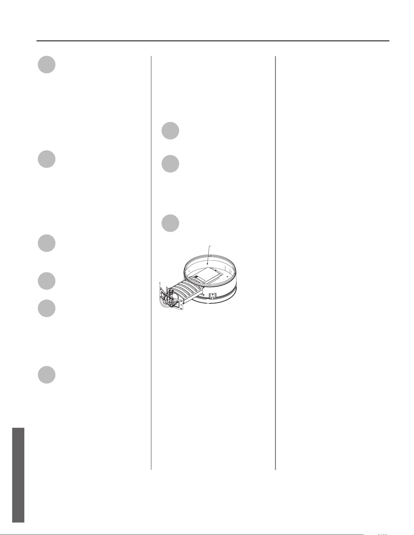
36 • Residenal Standard Gas Ultra Low Nox Water Heater Use and Care Guide
MAINTENANCE
5
Replace the screws which
secure the burner assembly to
the combuson chamber and
ghten securely. There should be no
space between the gasket part of the
burner door and combuson chamber.
WARNING! Do not operate the water
heater if the door gasket does not
create a seal between the burner door
and the combuson chamber.
6
Reconnect the manifold
tubing (3/4” wrench), pilot
tubing (7/16” wrench) to the
gas control valve/thermostat. Also
reconnect the FV sensor wires, wiring
harness, and igniter wire. (See Figure
46 for the correct posion of each
connecon.) Do not cross-thread or
apply any thread sealant to the ngs.
7
Reconnect the temperature
sensor wires to the LDO
module.
8
Follow the “Lighng Instruc-
ons” on page 23.
9
Check for leaks with the main
burner on by brushing on an
approved noncorrosive leak
detecon soluon. Bubbles forming
indicate a leak. Correct any leak found.
IMPORTANT: All leaks must be xed
immediately.
10
Replace the outer door.
Cleaning the
Combuson Chamber
and Flame-arrestor
See also “Inspect and Clean the Air
Filter” on page 33.
1
Follow the steps in “Remov-
ing the Manifold/Burner
Assembly” on page 35.
2
Use a vacuum cleaner/shop
vac to remove all loose debris
in the combuson chamber
(Figure 52). Use compressed air to
clear any dust or debris that may have
accumulated in the ame-arrestor.
3
Follow the steps in “Replacing
the Manifold/Burner Assem-
bly” on page 35.
Figure 52 - Combustion chamber
MAINTENANCE
COMBUSTION CHAMBER
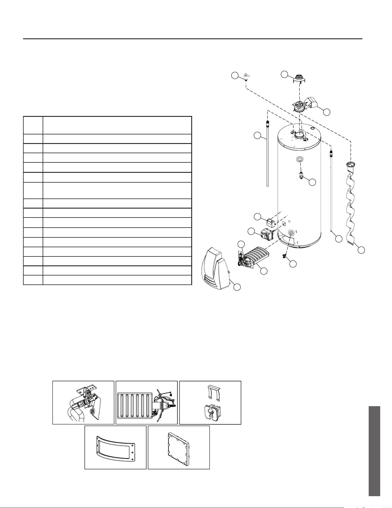
Residenal Standard Gas Ultra Low Nox Water Heater Use and Care Guide • 37
REPAIR PARTS
REPAIR PARTS
When ordering repair parts, always give the following
information:
1. Model, serial, and product number
2. Type of gas
3. Item number
4. Parts description
Item
No.
Parts Description
1 DRAFT HOOD
2 FLUE DAMPER
3 FLUE BAFFLE
4
HEAT TRAP/DIP TUBE COMBINATION
5 HEAT TRAP/ANODE ROD COMBINATION
6
TEMPERATURE & PRESSURE RELIEF VALVE
(LOCATED ON SIDE OR TOP)
7 DRAIN VALVE
8 GAS CONTROL VALVE/THERMOSTAT
9
LDO ASSEMBLY KIT
10
PILOT ASSEMBLY KIT
11 BURNER ASSEMBLY
12* MANIFOLD COMPONENT BLOCK
13* MANIFOLD DOOR GASKET
14* VIEWPORT ASSEMBLY
15 OUTER DOOR
Repair Parts List
* Not shown.
Listed Parts Kits and Illustrations
Item 10: Pilot Assembly kit, which contains the pilot, thermopile, and retainer clip (Natural Gas)
Item 11: Burner Assembly (Natural Gas)
Item 12: Contains manifold component block and retainer clip
Item 13: Contains manifold door gasket
Item 14: Contains viewport
1
11
7
6
6
2
4
3
8
9
15
5
10
NOTE: Damper
orientation may vary
Item #10
Item #11
Item #12
Item #13
Item #14

38 • Residenal Standard Gas Ultra Low Nox Water Heater Use and Care Guide
NOTES
NOTES

Residenal Standard Gas Ultra Low Nox Water Heater Use and Care Guide • 39
NOTES
NOTES

Copyright © 2023. All Rights Reserved
Limited Warranty provided by Manufacturer.