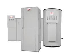
![EHS[150-2500] photo](https://manualsfile.com/images/appliances/k6/6a/k66a3pho3m6_0_1769908562266_thumbnail.webp)
Commercial Electric
Water Heaters
9kW – 900kW Input Models
CHP-I&S-01
INSTALLATION AND SERVICE MANUAL
1
If the information in this
manual is not followed exactly, a fire or
explosion may result causing property
damage, personal injury or loss of life
.
Do not store or use gasoline or other
flammable vapors and liquids in the vicinity of
this or any other appliance.
USE THIS APPLIANCE IF ANY
PART HAS BEEN UNDER WATER. THE
POSSIBLE DAMAGE TO A FLOODED
APPLIANCE CAN BE EXTENSIVE AND
PRESENT NUMEROUS SAFETY HAZARDS.
ANY APPLIANCE THAT HAS BEEN UNDER
WATER MUST BE REPLACED.
Installation and service must be performed by
Qualified Service Personnel Only
.
Factory warranty (shipped with unit) does not
apply to units improperly installed or improperly
operated.
Experience has shown that improper installation
or system design, rather than faulty equipment, is
the cause of most operating problems.
Excessive water hardness causing a lime/scale
build-up in the heater and/or on the immersion
heating elements is not the fault of the equipment
and is not covered under the manufacturer’s
warranty. (See Water Treatment and Water
Chemistry)
Do not energize electrical system before heater
is completely filled with water.
Damage caused
to the immersion heating elements by dry fire is
not covered under the manufacturer’s warranty.
Follow start up procedure in the manual.
Water heater corrosion and component failure
caused by air-borne chemical vapors is not
covered under the manufacturer’s warranty.
Corrosion damage caused by current leakage due
to improper grounding of electrical systems or
electronic components to the storage tank and
related piping is not covered by the
manufacturer’s warranty. Under no circumstance
will the manufacturer be liable for consequential
damages resulting from the installation or use of
this equipment. Correct installation procedure
and local codes must be adhered to.
This manual supplies information for the
installation, operation and servicing of the
appliance. It is strongly recommended that this
manual be reviewed completely before
proceeding with an installation. Upon receiving
equipment, check for signs of shipping damage.
Pay particular attention to parts accompanying
the water heater, which may show signs of being
hit or otherwise being mishandled. Verify total
number of pieces shown on packing slip with
those actually received. In case there is damage
or a shortage, immediately notify carrier.
CHECKING EQUIPMENT
WARNING:
NOTE: Retain this manual for future reference.
WARNING:
Improper Installation, Adjustment,
Alteration, Service or Maintenance
can cause injury or property damage. Refer
to this manual. For assistance or additional
information consult a qualified installer,
service agency or the electric utility.
SPECIAL INSTRUCTIONS
TO OWNER
WARRANTY
DO NOT

2
CONTENTS
Star
t-Up Procedure
Filling the Water Heater . . . . . . . . .22
Start-Up Checks . . . . . . . . . . . . . . .23
Shutdown Procedure . . . . . . . . . . . .24
Maintenance
T&P Relief Valve . . . . . . . . . . . . . .24
Water Chemistry . . . . . . . . . . . . . . .25
Flushing the Tank . . . . . . . . . . . . . .25
Sediment Removal . . . . . . . . . . . . .25
Scale Removal - Elements . . . . . . .25
T
rouble Shooting
Not Enough Hot Water . . . . . . . . . .27
Water Is Too Hot . . . . . . . . . . . . . .27
Water Heater Sounds . . . . . . . . . . .27
Leakage . . . . . . . . . . . . . . . . . . . . .27
Warranty . . . . . . . . . . . . . . . . . . . . . . . . . .1
Safety Warnings . . . . . . . . . . . . . . . .1
Checking the Equipment . . . . . . . . . .1
Codes . . . . . . . . . . . . . . . . . . . . . . . .4
Installation Requirements
Location . . . . . . . . . . . . . . . . . . . . . .4
Drain Pan Requirements . . . . . . . . . .5
Clearances . . . . . . . . . . . . . . . . . . . .6
Mounting . . . . . . . . . . . . . . . . . . . . .7
Water Connections . . . . . . . . . . . . . .7
Tank Construction . . . . . . . . . . . . . .8
Relief Valve . . . . . . . . . . . . . . . . . . .8
Thermal Expansion . . . . . . . . . . . . .8
Cathodic Protection . . . . . . . . . . . . .9
Electrical Ser
vice
Electrical Connection . . . . . . . . . . .9
Wire Sizing . . . . . . . . . . . . . . . . . . .9
Fusing . . . . . . . . . . . . . . . . . . . . . .9
Electrical Connection . . . . . . . . . . . .9
Jacket Assembly . . . . . . . . . . . . . . .10
Standard and Optional Controls . . .10
Components and Contr
ols
Terminal Block . . . . . . . . . . . . . . . .11
Fuses and Fuse Blocks . . . . . . . . . .12
Contactors . . . . . . . . . . . . . . . . . . .12
Transformer . . . . . . . . . . . . . . . . . .12
Immersion Thermostat . . . . . . . . . .13
Temperature Regulation . . . . . . . . .13
Risk of Scald Warnings . . . . . . . . .14
Temperature Control Sequencer . . .14
Display . . . . . . . . . . . . . . . . . . . . . .16
Temperature Adjustment . . . . . . . . .17
Error Messages . . . . . . . . . . . . . . . .18
Temperature Limit Control . . . . . . .18
Immersion Heating Elements . . . . .19
Safety Door Lock . . . . . . . . . . . . . .19
Low Water Cut-Off . . . . . . . . . . . . .20
Low Water Pressure Switch . . . . . .20
High Water Pressure Switch . . . . . .20
Manual Limiting Switches . . . . . . .20
Time Clock . . . . . . . . . . . . . . . . . . .21
Pilot Lights . . . . . . . . . . . . . . . . . . .21
Alarm Bell . . . . . . . . . . . . . . . . . . .21
3
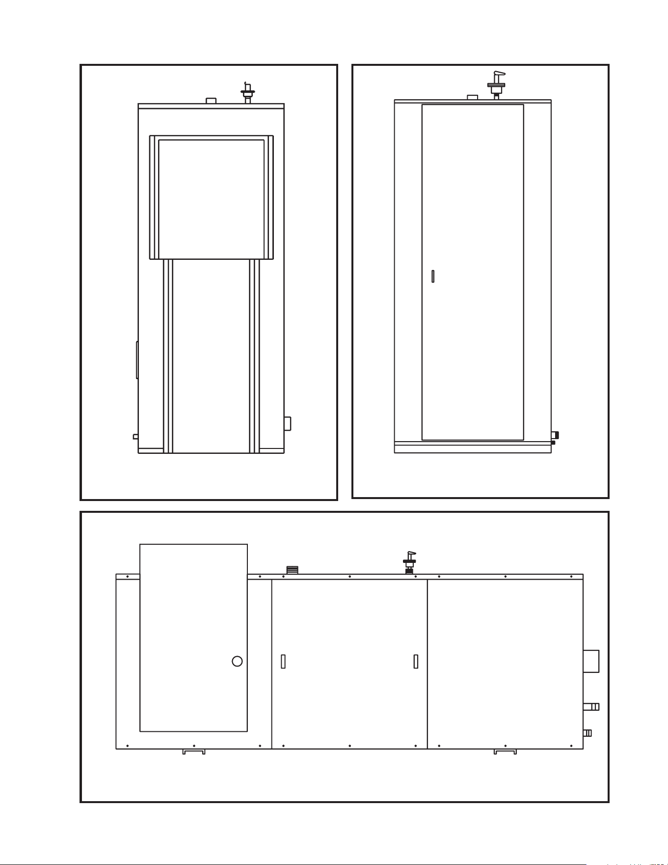
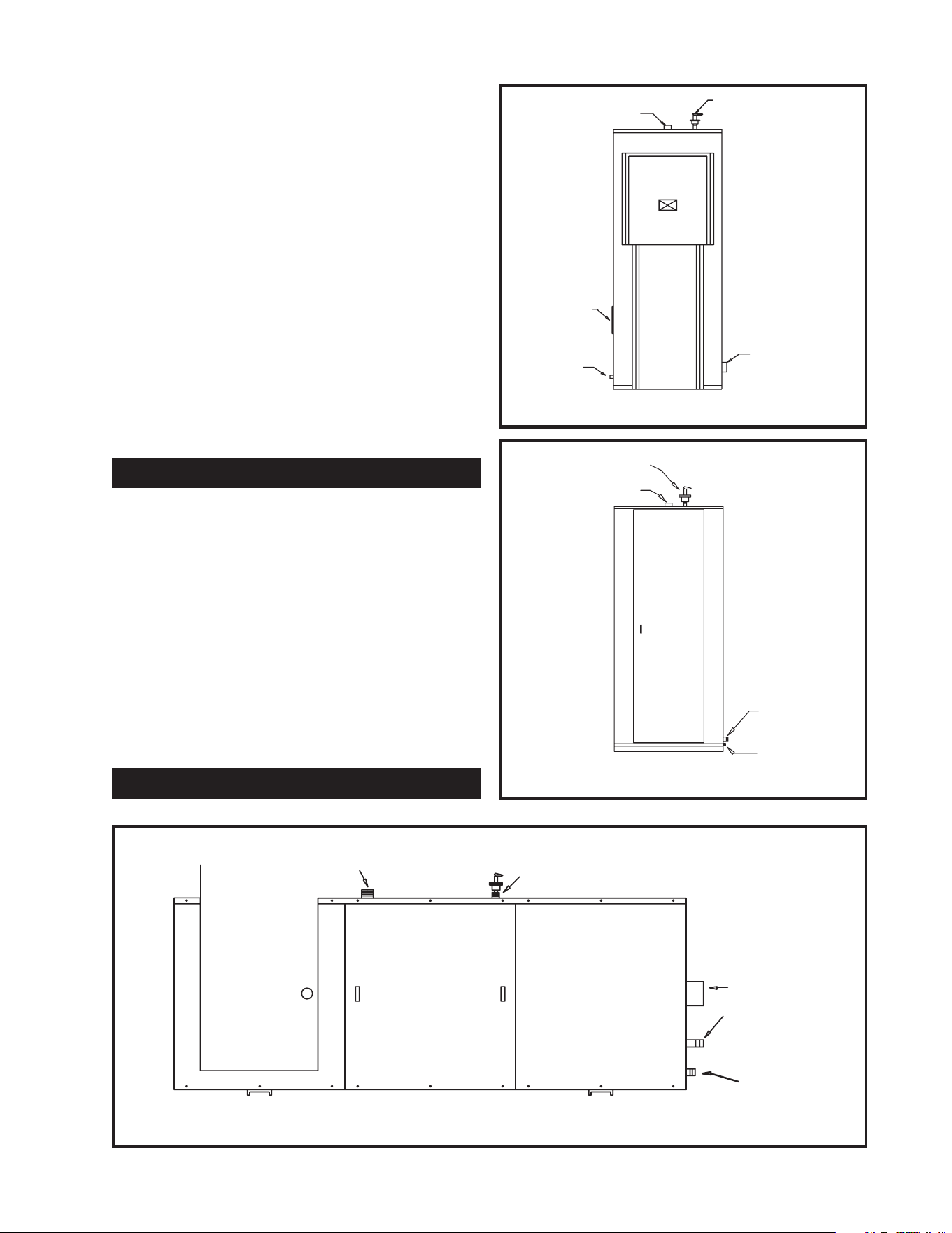
FIG. 2 Front View Vertical Square Models
FIG. 1 Front View Vertical Round Models
FIG. 3 Front View Horizontal Models
To minimize the possibility
of serious personal injury, fire or damage to
your appliance, never violate the following
safety rules.
1. Always keep the area around your
appliance free of combustible
materials, gasoline, and other
flammable liquids and vapors.
2. Never cover your appliance, lean
anything against it, store trash or
debris near it, stand on it or in any
way block the access to your
appliance.
Be sure to turn off power
when working on or near the electrical
system of the water heater. Never touch
electrical components with wet hands or
when standing in water. When replacing
fuses, always use the correct size for the
circuit. Do not test electrical system before
the water heater is completely filled with
water. Follow the start-up procedure.
Consult and follow
local Electrical Codes, Building and Fire
Regulations and other Safety Codes that
apply to this installation. Consult local
codes officials and electric utility company
to authorize and inspect all field installed
electrical connections.
The equipment shall be installed in accordance
with those installation regulations in force in the
local area where the installation is to be made.
These shall be carefully followed in all cases.
Authorities having jurisdiction shall be consulted
before installations are made. In the absence of
such requirements, the installation shall conform
to the latest edition of the National Electrical
Code, NFPA 70. When the appliance is installed
in Canada, it must conform to the CAE C22.1,
Canadian Electrical Code, Part 1 and/or local
Electrical Codes.
This complete appliance is design certified and
Listed by Underwriters Laboratories as a
commercial storage electric water heater. This
water heater bears the UL certification for the
United States as tested under the Standard for
Electric Booster and Commercial Storage Tank
Water Heaters, UL1453 and C-UL in Canada as
tested under the Standard for Construction and Test
of Electric Storage Tank Water Heaters,
CAN/CSA-C22.2 No. 110-M90. All water heater
storage tanks conform to the latest edition of the
ASME Boiler and Pressure Vessel Code, Section IV.
1. Locate the appliance so that if water
connections should leak, water damage
will not occur. When such locations
cannot be avoided, it is recommended that
a suitable drain pan, adequately drained,
be installed under the unit. Under no
circumstances is the manufacturer to be
held responsible for water damage in
connection with this unit, or any of its
components.
2. Insure that the appliance is located near
an acceptable drain so that the vessel can
be properly drained when performing
service or maintenance. The drain must
also provide adequate drainage in the
event of leakage the tank or related
piping. The drain must prevent water
damage to the adjacent area and lower
floors of the structure.
4
INSTALLATION PROCEDURE
LOCATION OF UNIT
OWNER WARNING
IMPORTANT:
CAUTION:
WARNING:
CODES
APPROVALS
The information contained in this manual
is intended for use by qualified professional
installers, service technicians or the electric
utility. Consult your local expert for
proper installation or service procedures.
3. The appliance must be installed so that
the electrical components are protected
from water (dripping, spraying, etc.)
during appliance operation and service
(replacing of fuses, elements, etc.)
4. Appliances located in a garage or parking
structure shall be installed so that the
jacket and all piping shall be located or
protected so that it is not subject to
physical damage by a moving vehicle.
5. The appliance must be installed on a level
floor. Shim the base as necessary if
leveling is required.
6. The floor on which the appliance is
installed must be capable of supporting
the total weight of the water heater when
completely filled with water.
Combustible floor locations may be used.
Maintain required clearances from
combustible surfaces.
7. The appliance must not be installed on
carpet.
8. The appliance must be installed indoors
where it is protected from exposure to
wind, rain and weather.
9. Locate the appliance as close as possible
to the point of major hot water usage, the
water piping and branch electrical circuit
wiring.
10. Insulate water piping to control heat loss
and possible condensation.
11. The appliance must be located in an area
that is not subject to freezing. The
ambient temperature of the space where
the appliance is installed must not go
below 32° F (0° C) or above 104° F (40° C).
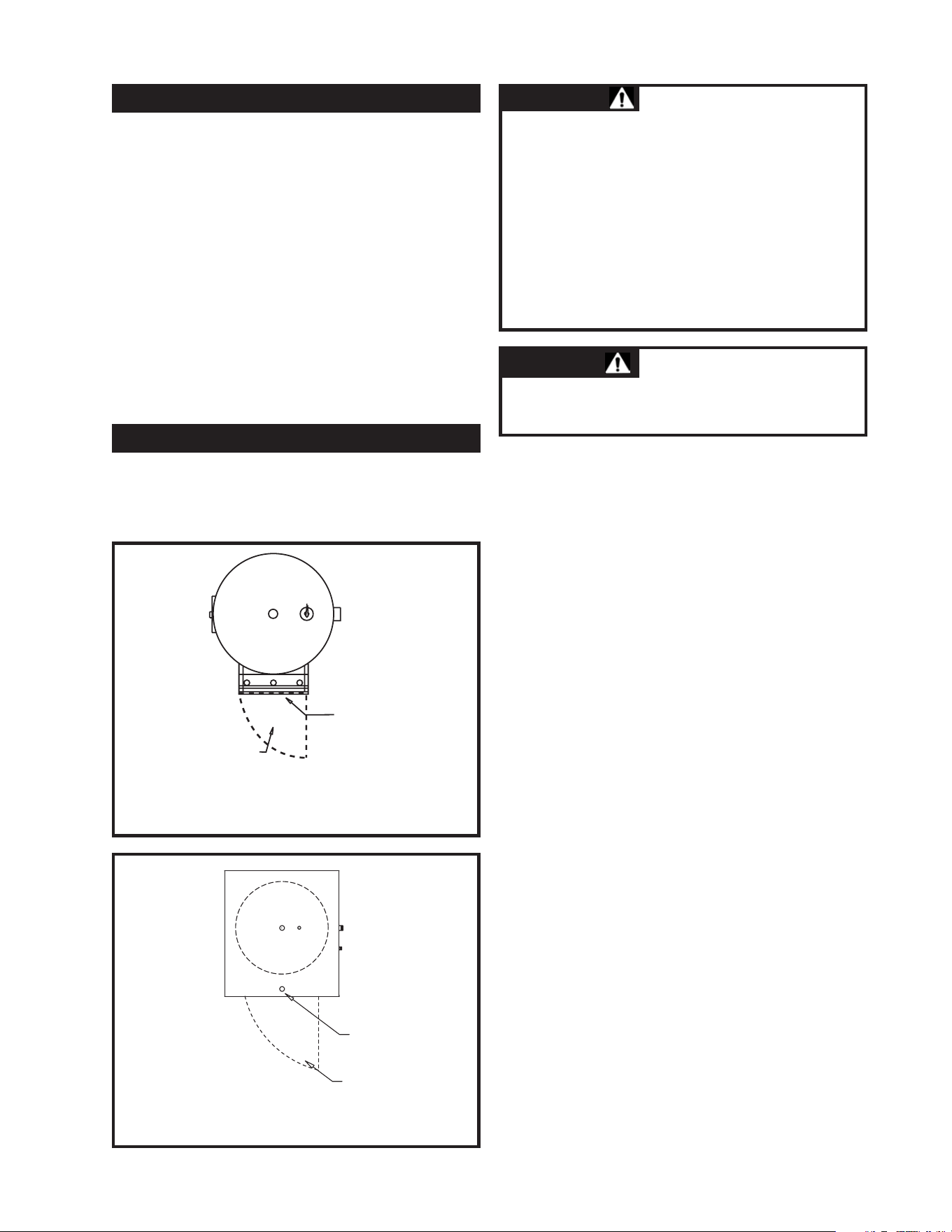
The lower pan of the horizontal water heater
jacket or vertical square water heater jacket is
specially constructed to function as a drain pan.
A water discharge opening is located in either end
of the pan. The discharge opening(s) used must
be piped to a suitable floor drain. If only one
discharge opening in the jacket pan is piped to a
floor drain, the unused opening must be plugged.
This jacket pan provides an extra margin of
protection against water damage on vertical
square or horizontally constructed models.
5
Drain Pan on Horizontal Models
and Vertical Square Models
1250 Gallons and Larger
CAUTION:
This water heater, as well as all water
heaters will eventually leak. Installation of
the water heater should be accomplished in
such a manner that if the tank, piping or
any connections should leak, the flow of
water will not cause damage to the
structure. For this reason, it is not
advisable to install the water heater in an
attic or upper floor. When such locations
can not be avoided, a suitable drain pan
must be installed under the water heater.
Drain pans may be fabricated or
purchased from your plumbing wholesaler.
The drain pan must be piped to an
adequate drain. Under no circumstances is
the manufacturer to be held liable for any
water damage in connection with this
water heater.
Right Side - 6" (15cm) (24" (0.61m) for high kW vertical square models with an
additional control panel on right side)
Rear - 0"
Left Side - 0"
Front - 36" (0.91m) for service access to controls and heating elements
Top - 12" (30cm) for service access to electrical service, water connections and piping
Water Pipes - 1" (25.4mm)
6
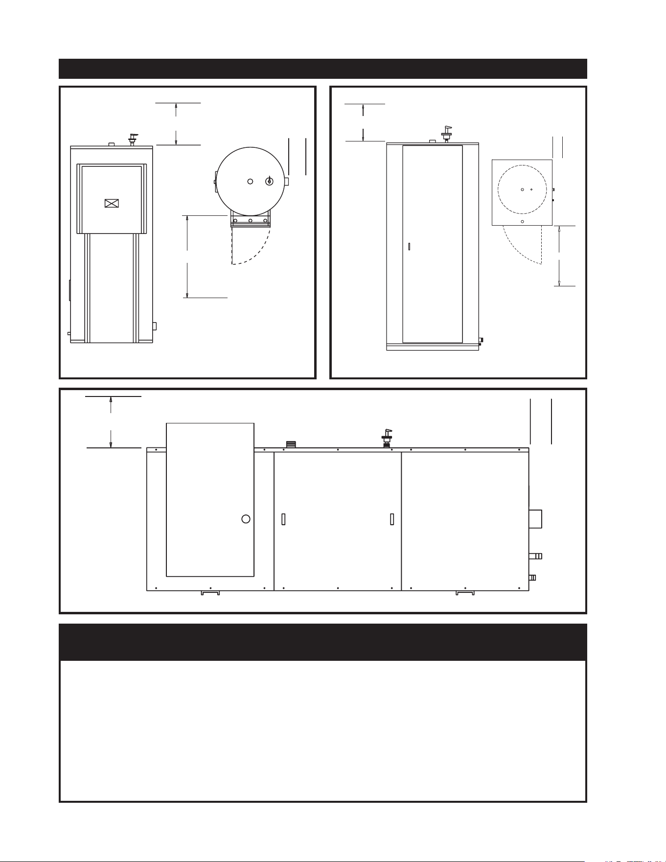
FIG. 5 Clearances from Combustible Construction
12"
36"
6"
FIG. 4 Clearances from Combustible Construction
CLEARANCES FROM COMBUSTIBLE CONSTRUCTION
6"
12"
FIG. 6 Clearances from Combustible Construction
TABLE A
CLEARANCES FROM COMBUSTIBLE CONSTRUCTION
12"
36"
6"
7
Maintain minimum specified clearances for
adequate operation. All installations must allow
sufficient space for servicing the electrical
components, water pipe connections, piping and
other auxiliary equipment, as well as the appliance.
Multiple appliances may be installed in a modular
water heater installation. Multiple appliances
may be installed side by side with minimum
clearance between the sides of adjacent
appliances because no service access is required
from the sides on most models. Note that high
kW input vertical square water heaters may have
an additional control access panel located on the
right side of the jacket requiring an additional
service access from the right side.
The water heater should be mounted to the floor
following applicable architectural and local code
requirements or accepted standards for the specific
site and model purchased. In areas prone to seismic
activity, it is recommended that the water heater be
mounted to the floor according to recommended
procedures for the site. In some geographic areas,
additional strapping or braces may be required,
consult local codes for specific requirements.
Proper mounting will help to make the water heater
less susceptible to seismic damage.
WATER CONNECTIONS
HANDHOLE
CLEANOUT
DRAIN
HOT WATER
OUTLET
TEMPERATURE & PRESSURE
RELIEF VALVE
COLD WATER
INLET
FIG. 7 Water Connections- Vertical Round Models
TEMPERATURE & PRESSURE
RELIEF VALVE
HOT WATER
OUTLET
DRAIN PAN
CONNECTION
COLD WATER
INLET
FIG. 8 Water Connections- Vertical Square Models
MOUNTING
WATER CONNECTIONS
TEMPERATURE & PRESSURE
RELIEF VALVE
HOT WATER
OUTLET
COLD WATER
INLET
MANWAY (OPTIONAL)
DRAIN
FIG. 9 Water Connections- Horizontal Models
Before making any
connections to the cold water inlet or hot
water outlet, insure that all piping is clean and
free of material or scale. This can usually be
accomplished by “blowing out the pipe.” Any
foreign material or scale entering the water
heater can adversely affect operation and
performance.
Inlet and Outlet Connections
For ease of service, install unions on the cold
water inlet and hot water outlet of the water
heater. The cold water inlet connection is located
on the lower right side of the water heater. A
manual shutoff valve should be installed
upstream on the cold water source as an isolation
device. The hot water outlet connection is located
on the top center of the water heater. A manual
shutoff valve should be installed downstream on
the hot water outlet source as an isolation device
in case the water heater must be disconnected
from the system.
This appliance uses a glass lined steel tank to
store the heated water for use. The storage tank
is constructed in accordance with the ASME
Boiler and Pressure Vessel Code requirements,
stamped and registered with the National Board
of Boiler and Pressure Vessel Inspectors. The
tank is furnished with threaded connections for
cold water inlet, hot water outlet, a relief valve
and a drain connection. The storage tank has a
hand hole for ease of inspection, cleanout and
service. An optional manhole may be specified
for greater ease of inspection. The interior of the
storage tank is glass lined and fired to 1600˚F
(871˚C) to insure a molecular fusing of glass and
steel to protect the steel base metal against
corrosion . A magnesium anode(s) is standard to
help prevent dissipation of the tank material by
electrolytic action.
This water heater is supplied with a temperature
and pressure relief valve(s) sized in accordance
with ASME Boiler and Pressure Vessel Code,
Section IV. Some water heaters may be supplied
with an optional pressure only relief valve. The
relief valve(s) is installed in the vertical position
and mounted in the tapping provided in the
storage tank. No valve is to be placed between
the relief valve and the water heater. To prevent
water damage, the discharge from the relief valve
must be piped to a suitable floor drain for
disposal when relief occurs. No reducing
couplings or other restrictions shall be installed in
the discharge line. The discharge line shall allow
complete drainage of the valve and line. Relief
valves should be manually operated at least once
a year. A relief valve that fails to completely
reseat and continues to discharge water must be
immediately replaced with a new, properly sized,
temperature and pressure relief valve.
A relief valve that discharges periodically may be
due to thermal expansion in a closed system. A
water heater installed in a closed system, such as
one with a backflow preventer or check valve
installed in the cold water supply, shall be
provided with means to control expansion.
Contact the water supplier or local plumbing
inspector on how to correct this situation.
DO NOT plug or cap the relief valve.
8
STORAGE TANK
NOTE:
When using copper tubing,
solder tubing to an adapter before attaching
to the threaded nipple connection provided
on the water heater. Soldering directly to the
threaded connection may harm a lining in the
nipple or damage the tank lining.
NOTE:
RELIEF VALVE
Avoid contact with hot
discharge water. Insure that no one is in
front of or around the relief valve discharge
line. Make sure that the extremely hot
water manually discharged from the relief
valve will not cause bodily injury or
property damage.
CAUTION:
THERMAL EXPANSION OF WATER
discharge!
Hydrogen gas can be produced in a hot water
system that has not been used for a long period of
time (generally two weeks or more). Hydrogen
gas is extremely flammable. To prevent the
possibility of injury under these conditions, we
recommend the hot water faucet be open for
several minutes at a sink close to the water heater
before you use any electrical appliance which is
connected to the hot water system. If hydrogen is
present, there will be an unusual sound such as air
escaping through the pipe as the hot water begins
to flow. There should be no smoking or open
flames near the faucet at the time it is open.
All installation procedures involving electric
power connection should only be performed by a
trained, certified electrician.
9
HINGED DOOR TO
ELECTRIC CONTROL
COMPARTMENT
ELECTRIC ACCESS
FIG. 11 Electric Power Connections –
Electrical Control Panel – Square Models
HINGED DOOR
TO ELECTRICAL
COMPARTMENT
ELECTRIC
ACCESS
FIG. 10 Electric Power Connections –
Electrical Control Panel – Round Models
The appliance, when installed, must be
electrically grounded in accordance with the
requirements of the authority having
jurisdiction or in the absence of such
requirements, with the latest edition of the
National Electrical Code, NFPA No. 70.
When the appliance is installed in Canada, it
must conform to the CAE C22.1, Canadian
Electrical Code, Part 1 and/or local Electrical Codes.
1. Use copper conductors only. All wiring
between the appliance and field installed devices
shall be made with copper wire suitable for at
least 75° C (167° F) temperature rating. If the
wiring from an old water heater installation was
aluminum, replace the old wire with copper wire.
2. The factory internal wiring is attached to a
terminal block inside the unit. The branch
circuit is connected to the terminal block
through an opening provided on the top of the
water heater electrical access panel.
3. Line voltage wire exterior to the appliance
must be enclosed in approved conduit or
approved metal clad cable.
4. To avoid serious damage,
DO NOT energize
the appliance until the system is full of
water
. Ensure that all air is removed from the
storage tank and piping before beginning
CATHODIC PROTECTION
ELECTRICAL CONNECTIONS
WATER HEATER IS
EQUIPPED FOR OPERATION ON ONE
VOLTAGE ONLY.
Check the rating plate on
the front of the control panel access for the
correct voltage and phase.
DO NOT use this
water heater with any other voltage other than
the voltage specified on the rating plate.
Failure to use the correct voltage can cause
problems that can result in death, serious
bodily injury or property damage.
DO NOT CONNECT THE
WATER HEATER TO AN IMPROPER
SOURCE OF ELECTRICITY!
CAUTION:
WARNING:
initial operation. Operation of a water heater
without a completely filled tank may result in
serious damage to the appliance and heating
element burn out.
5. The water heater should be connected with a
separate grounded branch circuit with over
current protection and disconnect switch. The
water heater should be grounded in accordance
with national and local codes. A ground
terminal is provided for ground connection only.
6. Provide the appliance with proper overload
protection in the branch circuit. It is suggested
that the electrician size the branch circuit at 125
percent of the heater ampere rating and further
increase wire size as necessary to compensate
for voltage drop in long runs. Branch circuit
voltage drop should not exceed 3% at the heater.
7. Voltage applied to the heater should not vary
more than +5% to -10% of the model and
rating plate marking for satisfactory operation.
8. A wiring diagram is provided with the water
heater for the electricians use.
Outer Jacket – The outer jacket assembly is
constructed from steel, galvanized on both sides.
The galvanized surface is specially prepared and
phosphate coated to allow application of a
multiple coat enamel paint process. This coating
process insures a long life from the jacket
assembly.
Your commercial electric water heater is
equipped with the following as standard
equipment.
• Low watt density immersion heating
elements with an incoloy sheath.
• Internal fusing of all elements in a
maximum of 48 amp increments provides
additional safety. Fuse cartridges are
related at 1,000,000 amps interrupting
capacity.
• A galvanized steel outer jacket and
electrical control panel are provided.
• Channel iron skid base.
• Electrical control panel is provided with a
hinged door and key lock.
• A glass lined steel tank constructed to
ASME specifications and provided with
magnesium anode(s).
• ASME rated temperature and pressure relief
valve provided by factory to insure safe
heater operation.
• Terminal block connections are installed by
the factory for safe easy wiring connection.
• Manual reset high water temperature limit
control.
• Immersion thermostat (one per 54kW of
input as standard).
• 180˚F (82.2˚C) temperature operation is possible
to provide water for sanitizing applications.
• Insulated to meet the latest edition of
ASHRAE 90.1 energy efficiency
standards.
• 3 year limited warranty provides protection
against failure of tanks due to defects in
material and workmanship in commercial
application.
• Underwriter’s Laboratories, Inc. listing for
all models as a commercial electric water
heater.
10
JACKET ASSEMBLY
Never turn on the electric
power or attempt to use this electric water
heater unless it is completely full of water.
Water must flow from the hot water faucet
before turning electrical power “ON.”
Operation of a water heater without a
completely filled tank may result in serious
damage to the appliance and heating
element burn out
CAUTION:
STANDARD EQUIPMENT
The following items are available as extra cost
options.
• Electronic low water cut-off prevents
energizing of the heater when it is not filled
with water.
• Pilot lights – Monitor on-off cycle of
contactors.
• Manual limiting switches with indicating
lights to permit heater kW input to be
manually limited as desired.
• Temperature and pressure gauges are
available installed flush with the jacket to
monitor heater performance.
• Electronic step controller modulates power
in-put and balances load to demand.
• Safety door interlock prevents opening of
access door while heater is energized.
• Shunt trip disconnect provides power
disconnect upon a control sensed
malfunction.
• Alarm bell provides an audible alarm to
warn of various control failures.
• Time clock to control off-on cycles of the
heater as programmed by the owner or
electric utility requirements.
• Low water pressure switch.
• High water pressure switch.
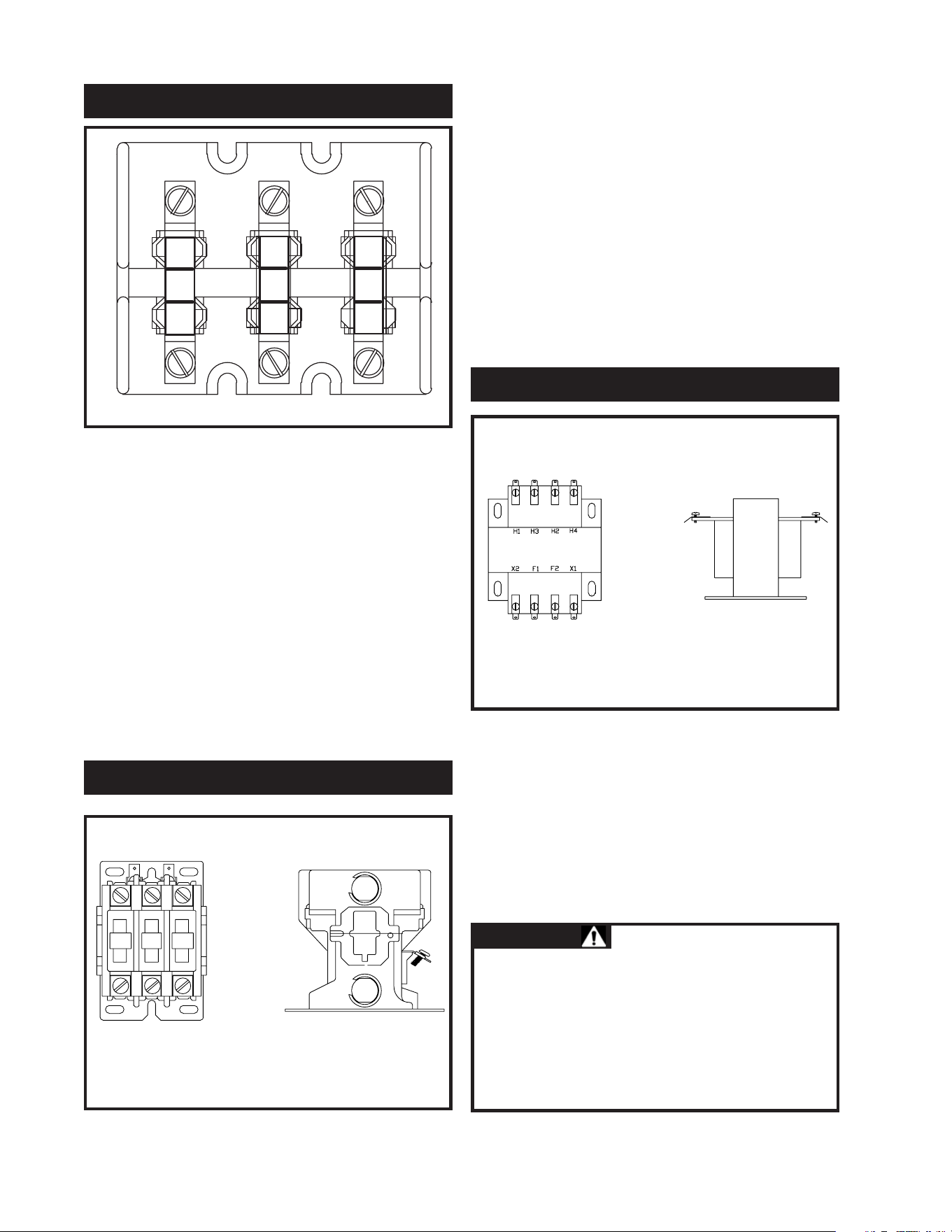
A main power terminal block is provided for field
connection of the branch power supply to the
electric water heater. All internal power circuits
to the immersion heating elements are connected
to the load side of the main terminal block. The
line side of the terminal block has individual lug
type connections properly sized for the
recommended copper field wire size.
11
OPTIONAL EQUIPMENT
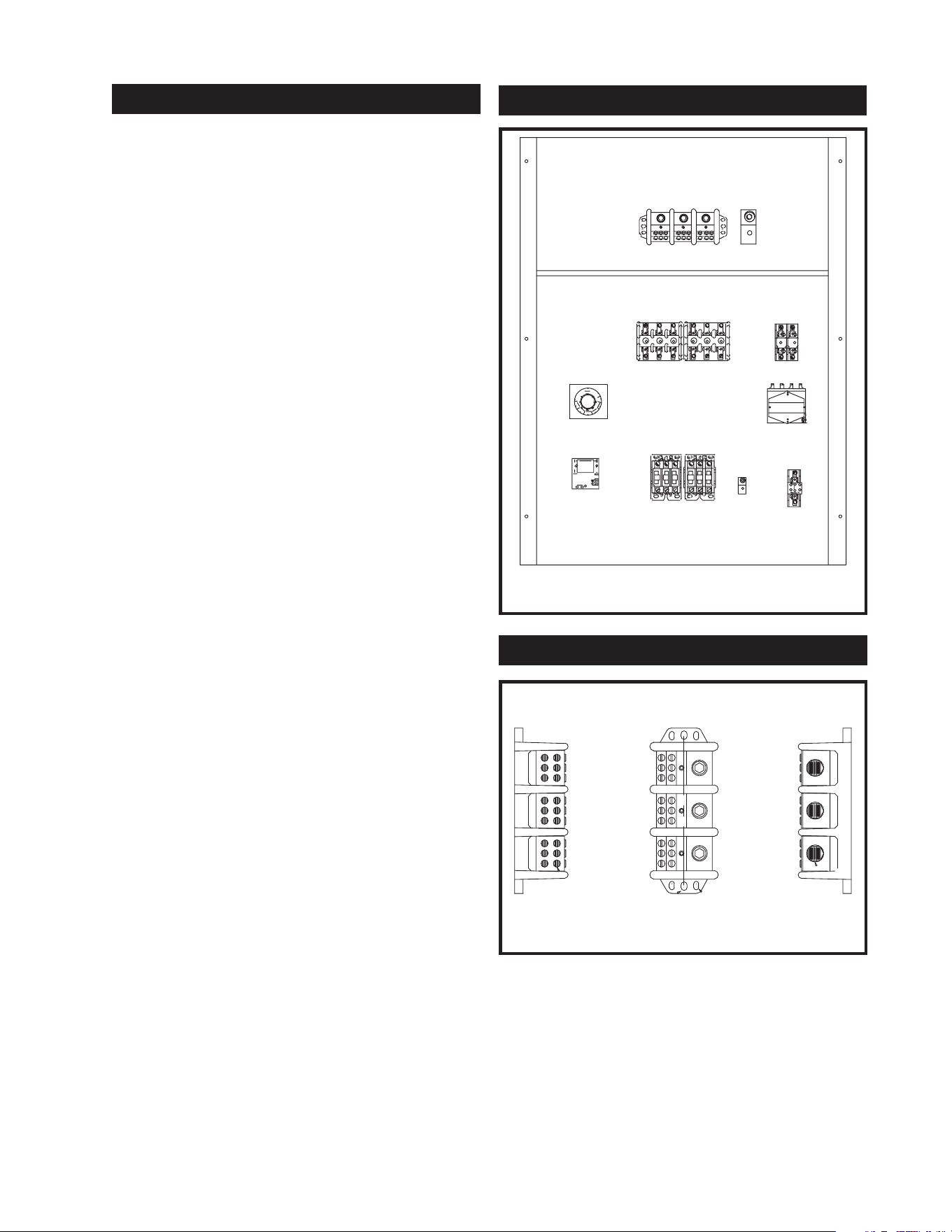
COMPONENTS AND CONTROLS
POWER CIRCUIT FUSE BLOCK
IMMERSION
THERMOSTAT
CONTACTOR
(IF EQUIPPED)
LOW WATER
CUTOFF
(IF EQUIPPED)
CONTROL
CIRCUIT
FUSE BLOCK
CONTROL
CIRCUIT
FUSE BLOCK
TRANSFORMER
TERMINAL BLOCK
GROUND LUG
FIG. 12 Electrical Panel Component Location
Drawing
TERMINAL BLOCK
LOAD
LINE
FIG. 13 Main Power Terminal Block
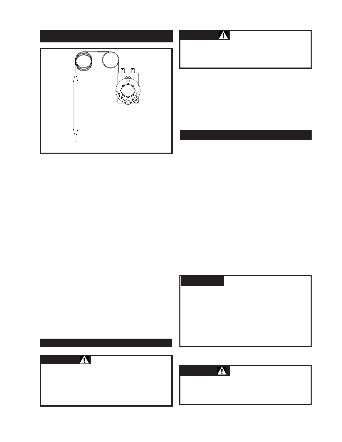
Each internal power circuit is fused for safety.
Each power circuit to an immersion element is
fused at a maximum of 48 amps. Power circuits
may be fused at lower current levels as needed to
balance current on three phase units. The power
circuit fuses are held by a spring loaded fuse
block rated for the voltage specified to operate
the water heater.
The control circuit is also fused on both the
primary and secondary sides of the control circuit
transformer.
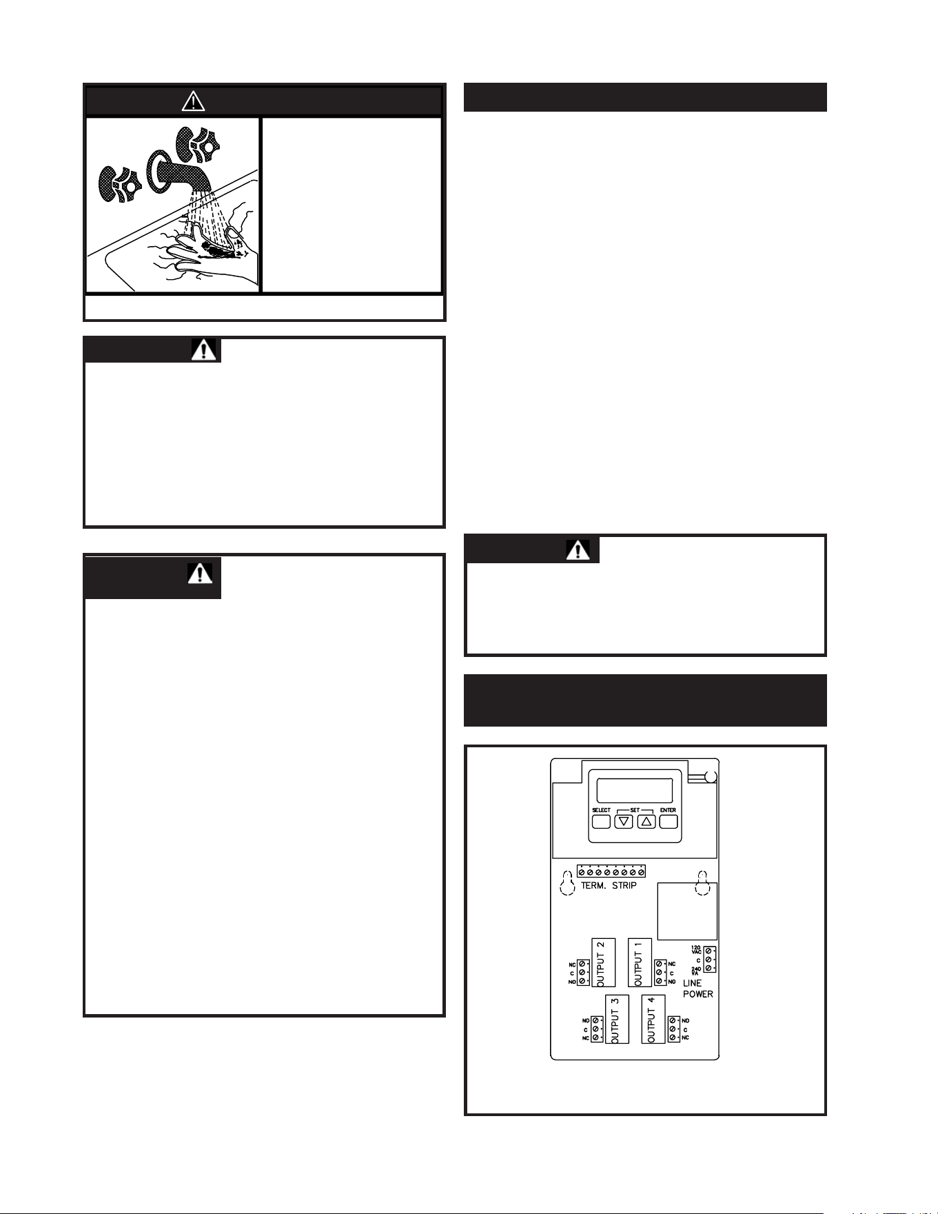
The power to the immersion electric heating
elements is switched by a definite purpose
magnetic contactor. The contactor is supplied
with 120 VAC from the control circuit when the
immersion thermostat senses a drop in stored
water temperature below the desired set point. A
magnetic coil in the contactor is energized to
complete the electrical circuit supplying power to
the immersion heating elements. When the
thermostat is satisfied, the contactor coil is de-
energized and power to the heating elements is
turned off.
CONTROL CIRCUIT TRANSFORMER
A transformer is used to reduce the line voltage to
120 VAC for internal control operation. The
transformer is fused on both the primary and
secondary side. The common side of the
secondary control circuit is grounded. The VA
rating of the control circuit transformer is based
on the load of the various components in the
water heater control circuit.
12
FIG. 14 Fuse Block with Power Circuit Fuses
FUSE AND FLUE BLOCKS
FIG. 15 Magnetic Contactor
CONTACTORS
CONTROL CIRCUIT TRANSFORMER
HAZARD OF ELECTRICAL SHOCK –
Before opening the electrical access panel
to adjust the thermostat or servicing the
water heater, make sure the electrical
supply to the water heater is turned “OFF”.
Failure to do this could result in death,
serious bodily injury or property damage.
WARNING:
FIG. 16 Control Circuit Transformer
This water heater uses an immersion
thermostat(s) to activate magnetic contactors
allowing current to flow to the immersion heating
elements. The standard control system uses one
immersion thermostat for each 54kW of electric
heating power in a water heater. As an option,
additional immersion thermostats may be
provided to add additional steps of thermostatic
control. The sensing bulb for each immersion
thermostat is immersed in the stored water in the
tank to provide quick, accurate response to
changes in water temperature, The thermostat
sensing bulb is located in the tank just above the
elements it is controlling. The immersion
thermostat set point is adjustable by rotating a
knob on the control. Turning the knob counter
clockwise decreases the temperature set point and
turning the knob clockwise increases the set
point. The temperature setting shown at the top
of the knob is the selected set point. The
immersion thermostat has a fixed 6°F (3.3°C)
differential.
Set temperature control to the lowest setting
which satisfies the hot water requirements of the
system. Lower water temperatures help minimize
scale formation on the heating elements. See
thermostat information below. For sequencer
specifications, consult controller literature.
This water heater has an adjustable thermostat to
control water temperature. The thermostat is
factory pre-set at approximately 125˚ F (51.7° C)
or less. Households with small children or
invalids may require a 120˚ F (48.9° C) or lower
temperature setting to reduce risk of scald injury.
Some states may require a lower temperature
setting. Check with your local codes or electric
utility for local requirements governing the
temperature setting. Remember, no water heating
system will provide exact temperatures at all
times. Allow a few days of operation at the
setting to determine the correct temperature
setting consistent with your needs.
13
WATER TEMPERATURE SETTINGS
TEMPERATURE REGULATION
IMMERSION THERMOSTAT(S)
FIG. 17 Immersion Thermostat with Adjustment Knob
HAZARD OF ELECTRICAL SHOCK –
Before opening the electrical access panel
to adjust the thermostat make sure the
electrical supply to the water heater is
turned “OFF”.
WARNING:
Full power is present whenever the cabinet
door is opened, even with the pilot
switch(es) turned off.
DANGER:
Hotter water increases the
risk of scald injury. Setting the temperature
selector dial higher provides hotter water,
which increases the risk of scald injury.
CAUTION:
(1) This water heater, when set at the lower
temperature setting, is not capable of
producing hot water of sufficient temperature
for sanitizing purposes.
(2) Higher stored water temperature increases
the ability of the heater to supply desired
quantities of hot water, however remember:
NOTE:
The maximum temperature
setpoint that should be set for the
Immersion Thermostats or programmed
into the Electronic Temperature Control
Sequencer is 190° F ( 88° C)
Always close the electrical control panel door
after making a temperature adjustment. Turn on
electricity.
1. Turn “OFF” the electrical power to the water
heater. If the power disconnect point is out of
sight, lock it in the open (“OFF”) position
and tag to prevent unexpected application
of power.
2. Open the water heater’s electrical access panel.
3. Adjust each immersion thermostat to the
desired temperature setting by turning the
adjusting knob. Each thermostat will be
factory pre-set to approximately 125° F
(51.7° C) or less as shipped.
4. Close the water heater’s electrical access panel.
5. Turn “ON” the electrical power to the
water heater.
ELECTRONIC TEMPERATURE
CONTROL SEQUENCER
14
CAUTION:
TEMPERATURE ADJUSTMENT
DANGER
HOT!
BURN
• Water temperature over 125˚F can
cause severe burns instantly or
death from scalds.
• Children, disabled and elderly are
at highest risk of being scalded.
• See instruction manual before
setting temperature at heating
appliance.
• If this appliance is used to produce
water that could scald if too hot,
such as domestic hot water use,
adjust the outlet control (limit) or
use temperature limiting valves to
obtain a maximum water temperature
of 125˚F. SEE MANUAL.
FIG. 18
WARNING: SHOULD OVERHEATING
OCCUR OR THE TEMPERATURE
CONTROLS FAIL TO SHUT OFF,TURN OFF
OR DISCONNECT THE ELECTRICAL
SUPPLY AT THE MAIN POWER
DISCONNECT EXTERNAL TO THE
APPLIANCE.
WARNING:
• Water temperature over 125˚ F (51.7°C)
can cause severe burns instantly or death
from scalding.
• Children, disabled and elderly are at
highest risk of being scalded.
• See instruction manual before setting
temperature at heating appliance.
• Feel water before bathing or showering.
• If this appliance is used to produce water
that could scald if too hot, such as
domestic hot water use, adjust the outlet
control (limit) or use temperature
limiting valves to obtain a maximum
water temperature of 125˚ F (51.7° C).
ELECTRONIC TEMPERATURE
CONTROL SEQUENCER
DANGER:
FIG. 19 Electronic Temperature Control
with Digital Display
The water heater uses an optional adjustable
electronic temperature control to provide staged
ON/OFF control of the electric heating elements.
Operation is based on temperature input from an
immersion temperature sensor. The sensor is a
positive coefficient platinum thermistor. The
sensor is placed in a well located above the
heating elements it is controlling. A liquid crystal
display is provided to indicate sensed temperature
and operating parameters. The temperature
control may operate in as many as four stages of
control. For more stages of operation, multiple
electronic temperature control sequencers are
installed and wired to operate in series.
Set Point Adjustment Range: Max setting
220° F (105° C).
Temperature Accuracy: +/- 1° F.
Display Resolution: 1° F via Liquid Crystal
Display (LCD). Sensor: Thermistor 4.8 ohms/° F.
Operating Humidity: 5 - 95% RH
Noncondensing.
Operating Ambient Temperature: -30° to 125° F.
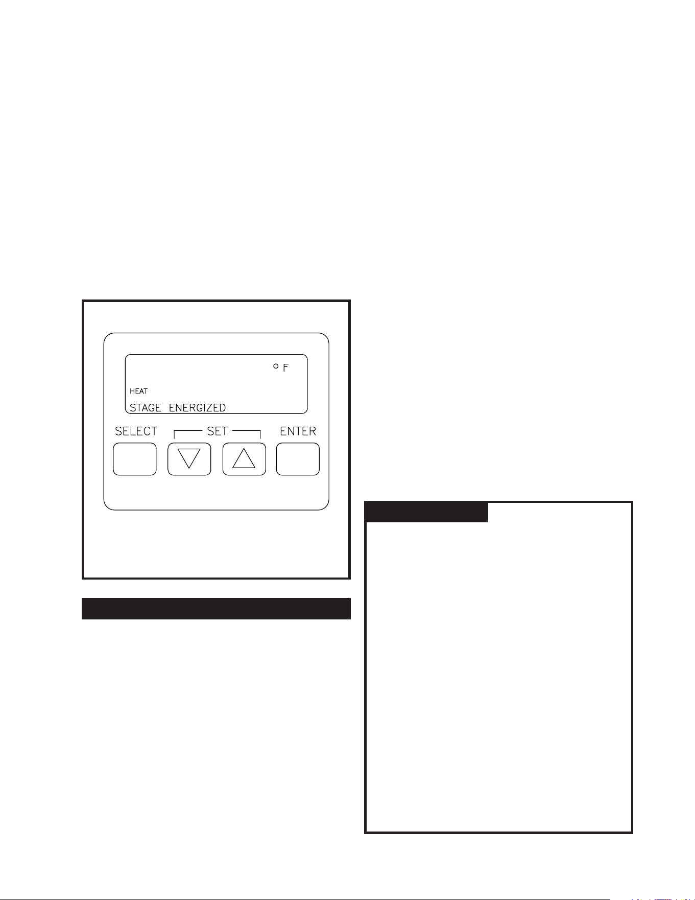
Access to the control is achieved by opening the
hinges control panel door covering the electrical
components. Four programming keys are
provided to program set point and differential
values for each stage and to control the display.
The four keys are
Select, Up arrow, Down arrow
and
Enter.
Select Key - Sequentially prompts the user as to
what parameter is being displayed: set point,
differential, stage energized, operation mode
(heat), indication of assigned stage (1,2,3). Once
the last parameter value has been viewed,
pressing the
Select key will display the control
values again from the beginning of the display
loop.
Up and Down Arrow Keys - Allow the displayed
parameter to be increased or decreased. After
pressing the Select key, a control value can be
changed by using the
Arrow keys. Control
values will be increased or decreased by 1° F for
each time the Arrow keys are depressed.
Enter Key - Places the new value into the
memory of the microprocessor.
15
125
1 2 3 4
FIG. 20 Electronic Temperature Control
Digital Display and Programming Keys
SPECIFICATIONS
A control value or
operation will not be entered in the memory of
the microprocessor until the
Enter key is
pressed.
Control values and operation selection will
remain in the device memory even after power
is removed.
Select and Enter Keys simultaneously
pressed - Changes operation mode of the
control from heat to cool mode. DO NOT
CHANGE THIS SETTING.
This control
must always be in the “HEAT” position for
proper operation of the water heater.
When all stages have been programmed the
display will revert back to sensed temperature
and load energized status.
IMPORTANT:
Once power is applied to the temperature
controller the display will countdown from 210
until the display reads zero. All outputs are
de-energized at this time. This countdown
process will repeat each time main power is
interrupted. To avoid viewing this entire
countdown, press the
Select key. The display will
now show normal readings: load (sensed)
temperature and stages energized. At any time
during the programming procedure, the display
will revert back to showing the sensed
temperature and stage status indication 60
seconds after the last programming key is pushed.
Each stage on the controller has its own
independent set point and differential which are
determined by the programming keys. Each
stage of heating is de-energized as the sensed
temperature reaches the programmed set point.
Each available stage of heating is energized as the
sensed temperature reaches the set point minus
the differential.
EXAMPLE:
Using stage one of the control as an example, the
corresponding load would be energized and
de-energized at the following temperatures based
on the programmed settings.
Settings
Set point: 160
o
F
Differential: 8
o
F
Output Energized
Stage One: Energized at 152
o
F
Output De-energized
Stage One: De-energized at 160
o
F
Each available stage of operation must be
programmed with a set point and a differential. If
two stages are programmed with the same set
point and differential the control will sequence
both stages on and off with only a slight delay
between switching of the stages. The control is
normally programmed with a few degrees
difference between the set point of each stage to
sequence individual stages on as required by
demand. This will allow input to be balanced to
system demand. The exact settings will be
determined by your system hot water
requirements.
Based on your system requirements, determine
the set point and switching differential for each
stage of operation and enter into the worksheet
below.
Pro
gramming W
orksheet
Stage 1:
Set Point 1 ___________ Off at ___________
Differential 1 ________ On at __________
Stage 2:
Set Point 2 ___________ Off at ___________
Differential 2 ________ On at __________
Stage 3:
Set Point 3 ___________ Off at __________
Differential 3 ________ On at _________
Stage 4:
Set Point 4 ___________ Off at __________
Differential 4 ________ On at _________
These values will be programmed into the
temperature controller.
16
DISPLAY
SETUP OF THE TEMPERATURE
CONTROLLER
Stag
e Set Point Differential
1 125˚ F 2˚ F
2 123˚ F 2˚ F
3 121˚ F 2˚ F
4 120˚ F 2˚ F
Re-program the set points and differentials to
meet your system hot water requirements.
The operating control uses a Liquid Crystal
Display for interactive prompting during
programming and display of sensed and assigned
set point and differential values. Programming is
accomplished through the use of the four
programming keys.
1. Turn “OFF” the electrical power to the water
heater. If the power disconnect point is out of
sight, lock it in the open (“OFF”) position and
tag to prevent unexpected application
of power.
2. Open the water heater’s electrical access panel.
3. Verify that the unit is properly applied and the
model number on the rating plate correctly
identifies the unit.
4. Turn the electrical power switch to the “ON”
position. The control will begin counting
down from 210. This countdown sequence
will last for approximately 3-1/2 minutes.
5. To override this time delay, press
Select.
6. Press Select to display the current stage
set point.
7. Press
Up Arrow key to increase or Down
Arrow
key to decrease to the desired
set point.
8. Press
Enter to enter the displayed value
into memory.
9. Press
Select to display the current stage
switching differential.
10. Press
Up Arrow key to increase or Down
Arrow key to decrease to the desired
switching differential.
11. Press
Enter to enter the displayed value
into memory.
12. Repeat steps 6 through 11 to program each
additional stage.
13. Press
Select, Select, Select, Select (4 times)
to return to stage 1 parameters. Scroll
through the programming loop a second
time to confirm that the appropriate values
have been entered into memory by
pressing Select.
14. Press
Select after viewing the switching
differential for the final stage to display
stored water temperature.
15. Close the water heater’s electrical
access panel.
16. The temperature control is now ready
for operation.
17
When power is initially
applied to a new water heater, the control
points will be pre-programmed. The
factory final quality test sets the unit for
test firing. The preset values are as follows:
NOTE:
PROGRAMMING
TEMPERATURE ADJUSTMENT
HAZARD OF ELECTRICAL SHOCK –
Full power is present whenever the cabinet
door is open and the main power
disconnect is in the “ON” position, even
with the pilot switch(es) turned off.
WARNING:
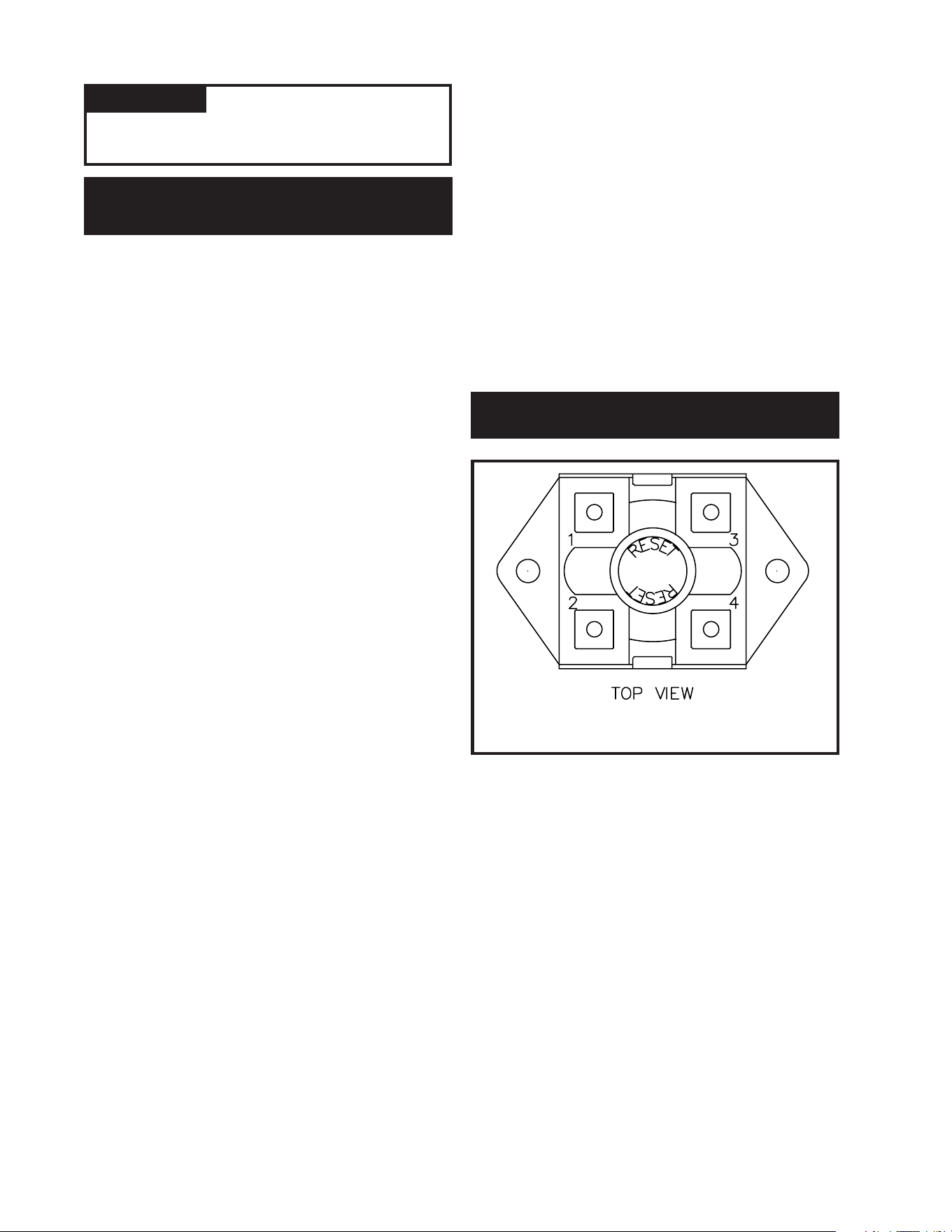
FIG. 21 High Water Temperature Limit Control
- Fixed Setting
ERROR MESSAGES DISPLAYED BY THE
ELECTRONIC TEMPERATURE CONTROL
There are seven error messages that can be
displayed in response to software or hardware
problems with the boiler’s internal electronic
temperature control. The error codes that may be
seen flashing on the display are:
SF - Sensor Failure
The display flashing SF indicates an
out-of-range or defective sensor. Make sure
sensors are properly installed, wired and
connected to the control. Correct sensor
installation or replace sensor.
EF- EEPROM Failure
The values read form the EEPROM are not
the same as the values written into the
EEPROM. This error cannot be field
repaired. Replace the water heater’s
electronic temperature control.
CF - Calibration Failure
The calibration resistor reading was not
within the range of the Analog to Digital
converter. This error cannot be field repaired.
Replace the water heater’s electronic
temperature control.
OF - Stray Interrupt Failure
An unused interrupt occurred. This error
cannot be field repaired. Replace the water
heater’s electronic temperature control.
CE - Configuration Error
The device hardware was configured to a
nonexistent device. This error cannot be field
repaired. Replace the water heater’s electronic
temperature control.
OE - ROM Error
The internal ROM of the microprocessor in
the boiler’s electronic temperature control is
defective. This error cannot be field repaired.
Replace the water heater’s electronic
temperature control.
AE - RAM Error
The internal RAM of the microprocessor in
the boiler’s electronic temperature control is
defective. This error cannot be field repaired.
Replace the water heater’s electronic
temperature control.
The unit is equipped with a fixed setting, manual
reset high water temperature limit control. The
water heater temperature limit control has a fixed
limit setting of 195° F (90.6° C). If water
temperature exceeds the limit set point, the limit
will break the control circuit and shut down the
unit. The limit control can only be reset after the
water temperature has cooled below the set point
of the limit. The high water temperature limit
control is mounted on the surface of the tank,
above the heating element installed at the highest
point in the tank. The high limit control is reset
by pushing the red reset button on the control.
Operation of the limit control usually indicates a
major problem with the thermostat, contactors or
heating elements.
Do not continue to push the
18
HIGH WATER TEMPERATURE
LIMIT CONTROL
The control values
programmed into memory will not be lost
because of a power failure.
NOTE:
The high limit control will not
reset until the water temperature has
dropped below the set point of the high limit.
reset multiple times.
The source of the problem
must be found and corrected to insure proper
operation. The limit control is covered with an
insulation blanket which must be removed to
push the red reset button. The blanket of
insulation must be replaced before the power is
turned on and the water heater is returned to
service.
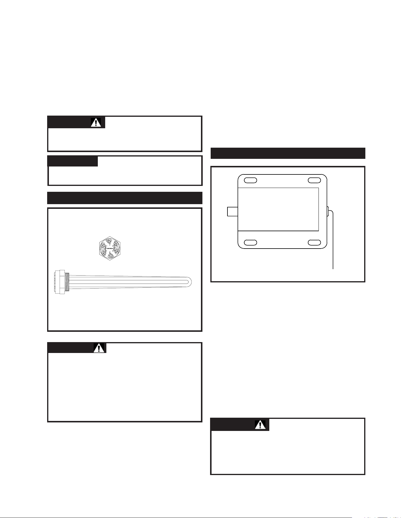
The heating input to this commercial electric
water heater is provide by low watt density
immersion heating elements. The heating
elements are constructed from an incoloy sheath
with a tin plate on the exterior surface. Three
element blades are mounted on a single hex-head
screw-in mounting flange. The element flange
mounts into a 1 1/2” NPT threaded connection
welded to the storage tank. The hex-head screw-
in mounting flange seals to the tank with an “O”
ring gasket at the base of the threaded portion of
the flange. The tank flange has a matching recess
for the “O” ring gasket to insure a proper water
tight seal. . The “O” ring element gasket must be
replaced with a new gasket when an element is
removed for inspection, cleaning or replacement.
The optional safety door interlock is an
electrically operated locking pawl that is
energized when main power to the water heater is
turned “ON.” The interlock is mounted to the
inside of the electrical control panel door and
extends behind a locking flange when energized.
Main power may be turned off and the electrical
access door may be opened for service.
With the door open, main power may be
energized if required to service or troubleshoot
the operation of selected components.
19
SAFETY DOOR INTERLOCK (Optional)
FIG. 22 Immersion Heating Element
NOTE:
IMMERSION HEATING ELEMENT
HAZARD OF ELECTRICAL SHOCK –
Before opening the access panel to remove or
service the immersion heating elements,
make sure the electrical supply to the water
heater is turned “OFF”. Failure to do this
could result in death, serious bodily injury
or property damage.
WARNING:
Disconnect the main power
to the heater before opening the element
access panel to reset the high limit control.
CAUTION:
FIG. 23 Safety Door Interlock
HAZARD OF ELECTRICAL SHOCK –
Full power is present whenever the cabinet
door is opened and main power is turned
“ON”, even with the pilot switch(es) turned off.
DANGER:
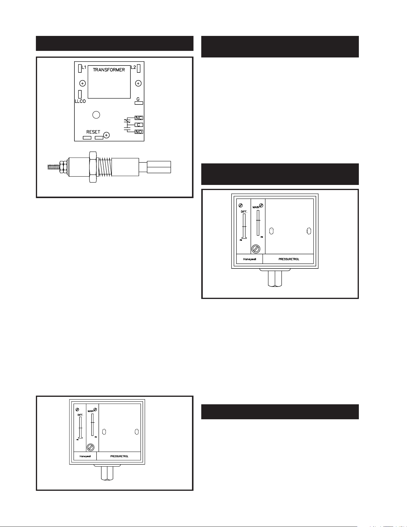
This water heater may be equipped with an
optional electronic low water cut-off installed at
the factory. This low water cut-off device uses a
water level sensing probe located above the
heating element installed in the highest point in
the storage tank. If the internal water level drops
below this point, the low water cut-off will shut
down operation of the heating elements. An
electronic type low water cut-off is available as a
factory supplied option on all models. The
optional electronic low water cut-off has an LED
located on the main circuit board. This LED will
be illuminated and the control circuit will be
completed between the common and normally
open contacts on the circuit board when the
sensing probe is below the water level in the
storage tank. An optional manual reset function
and test button is available on the electronic low
water cut-off. The operation of a low water cut-
off should be inspected every six months.
A low water pressure switch is available as an
option on this water heater. A water pressure
switch is used to monitor the water pressure in the
water heater storage tank. If the water pressure
drops below an adjustable set point, the control
circuit is opened and operation of the water
heater is shut down. The low water pressure
switch may be specified with either a auto-reset
function or a manual reset function on low water
pressure.
A high water pressure switch is available as an
option on this water heater. A water pressure
switch is used to monitor the water pressure in the
water heater storage tank. If the water pressure
rises above an adjustable set point, the control
circuit is opened and operation of the water
heater is shut down. The low water pressure
switch may be specified with either a auto-reset
function or a manual reset function on high water
pressure.
As an option, a switch or multiple switches may be
provided to interrupt the 120 VAC control circuit
feed to the contactor coil or coils from the
immersion heating thermostat(s). This switch may
be used to manually turn off a portion of the heating
element input. This feature may be used to reduce
20
Control Board
Probe
LED
FIG. 24 Electronic Low Water Cut-off Control
LOW WATER PRESSURE SWITCH
(Optional)
FIG. 25 Low Water Pressure Switch
LOW WATER CUTOFF (Optional)
HIGH WATER PRESSURE SWITCH
(Optional)
FIG. 26 High Water Pressure Switch
MANUAL LIMITING SWITCHES (Optional)
electrical input of the water heater in the summer
months when ground water temperatures are
warmer and full electrical input from the
immersion heating elements is not required. The
water heater may be restored to full input by
moving the switches to the “ON” position.
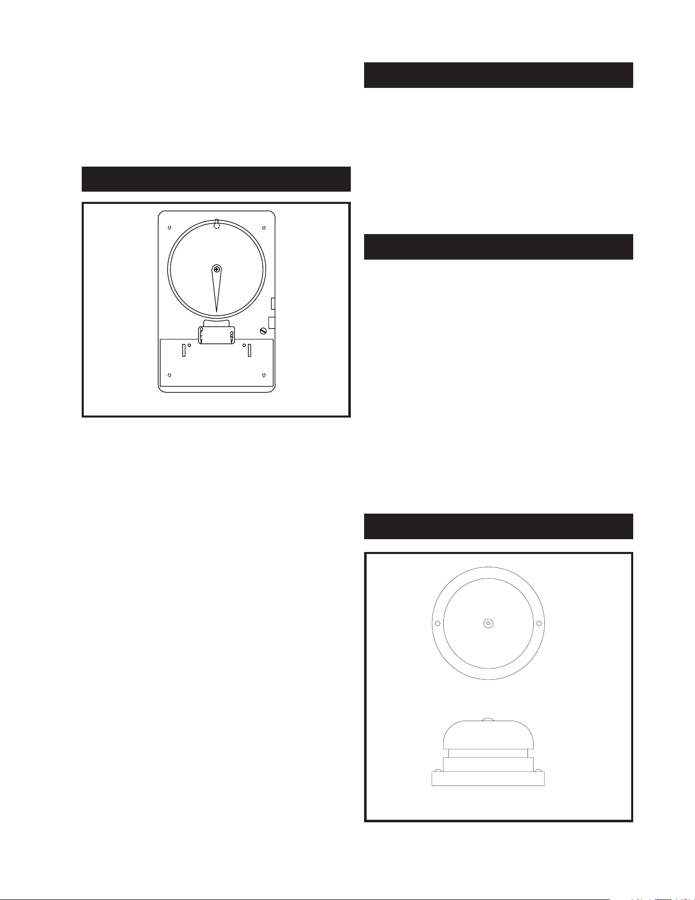
The water heater may be provided with an
optional time clock. The time clock will allow
the water heater to be turned on and off with a
pre-set schedule. The time clock may be
specified with a 24 hour scheduling period or
with a 7 day scheduling period. By the
adjustment of the setpoints on the time clock, the
water heater may be turned off when hot water is
not needed or in periods when the building may
not be occupied. The time clock allows the water
heater to automatically cycle on in advance of the
time when hot water may be needed. This will
insure that hot water is always available yet save
energy when there are scheduled periods when
there will be no requirement for hot water. This
feature is especially useful for schools and
building that are occupied on a fixed schedule.
As an additional feature, time clocks may be
furnished with a spring wound carry-over
function to insure that a switching schedule is
maintained in periods where there may be power
interruptions. The time clock works by making
and breaking the 120 VAC control circuit to the
contactor coils to shut down operation of the
heating elements in the desired time periods.
The water heater may be provided with optional
pilot lights to provide an external indicator for
each contactor or stage of heating elements that is
energized. Each pilot light is wired in parallel
with the 120 VAC control circuit feed to the
contactor coil(s). The pilot will be turned on as
the contactor coil(s) is energized by the
temperature controls.
Shunt trip disconnect provides a power
disconnect upon a control sensed malfunction via
a circuit breaker installed in the main power
supply to the water heater. The circuit breaker is
shipped as a separate item that must be field
installed. The water heater 120 VAC control
circuit provides a feed to the circuit breaker that
will shut down main power on either a low water
level condition (if equipped) or high water
temperature. Once the water heater is installed
and all power is connected, the toggle switch that
arms the shunt trip must be placed in the on
position to provide the shunt trip function on the
desired control sensed malfunction.
21
FIG. 27 Time Clock
TIME CLOCK (Optional)
PILOT LIGHTS (Optional)
SHUNT TRIP DISCONNECT (Optional)
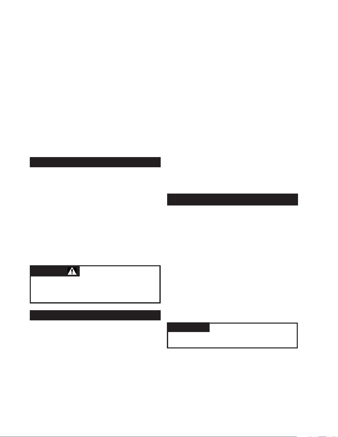
ALARM BELL (Optional)
FIG. 28 Alarm Bell
The cold water supply must be
left in the open position when the water
heater is in use.
An alarm bell with silencing switch is available as
an option on this water heater. The alarm bell can
be used to provide an audible indication of a
control sensed malfunction. The user must
specify the safety function or multiple safety
functions that the alarm bell will sound on when
the water heater is ordered from the factory. The
alarm bell typically is used to indicate a low water
condition or a high water temperature condition.
The alarm is furnished with a silencing switch to
turn off the audible alarm while trouble shooting
a control sensed malfunction that is indicated by
an audible alarm. Once the control sensed
malfunction is corrected, the silencing switch
must be returned to the “ON” position to
re-establish the audible alarm function.
Never operate the heating elements without
being certain the water heater is filled with
water and a temperature and pressure relief
valve is installed in the relief valve opening on
top of the heater.
The pilot switch(es) (if equipped) mounted on the
control cabinet permit the heater to be turned on and off
without having to operate the electrical disconnect
switch. The pilot switch interrupts only the 120 VAC
control circuit in the water heater. Full power is still
present at the terminal block, fuses and contactors.
A relief valve that discharges periodically may be
due to thermal expansion in a closed system.
Many water systems are equipped with pressure
reducing valves, check valves or back flow
preventers which may cause the water system to
be closed. As water is heated it will expand in
volume due to thermal expansion. The system
must make allowance for this expansion. If an
expansion tank is not provided in the system,
water pressure may increase to the point where
the water heater’s temperature and pressure relief
valve opens to relieve the excess pressure. The
temperature and pressure relief valve is not
intended for the constant relief of thermal
expansion. This is an unacceptable condition and
must be corrected.
Do not plug or cap the relief
valve discharge!
A properly sized expansion
tank is typically installed in the potable water
system to relieve the pressure built up by thermal
expansion of heated water. Consult your local
plumbing contractor and plumbing wholesaler for
assistance in properly selecting an expansion tank
for your system.
As the water heater operates, there may be noises
generated by the expansion and contraction of the
metal parts of the water heater and related piping.
These noises may occur during periods of heat up
or cool down. They do not represent harmful or
dangerous conditions.
1. Insure that the electrical power to the water
heater is in the “OFF” position. If the power
disconnect point is out of sight, lock it in the
open (“OFF”) position and tag to prevent
unexpected application of power.
2. Close the water heater drain valve(s).
3. Open a nearby hot water faucet to allow the
air in the system to escape as the tank fills.
4. Fully open the cold water inlet valve to the
water heater to begin filling the heater and piping.
5. Check the nearby hot water faucet to verify
that air is exiting the tank as it fills with water.
Allow water to run until a constant flow is
obtained at the faucet. This will insure that all
air is purged from the system.
22
START-UP PROCEDURE
Full power is present whenever the cabinet
door is opened, even with the pilot
switch(es) turned off.
DANGER:
THERMAL EXPANSION OF WATER
FILLING THE WATER HEATER
NOTE:
6. While the tank is filling, open the electrical
control panel and set the thermostat(s) to the
desired water temperature. If equipped with
multiple thermostats, all individual
thermostats may be adjusted to the same
temperature set point or they may be set a 2°F
to 4°F (1˚C to 2˚C) apart to step the elements
on in stages.
7. Insure that any pilot switches or manual
limiting switches are placed in the
“ON” position.
8. When a constant flow is obtained at the
faucet, it may be turned off. The temperature
and pressure relief valve should be manually
opened to insure that there is no captive air in
the storage tank. A constant stream of water
must flow from the manually opened relief
valve. Release the handle on the relief valve
and allow it to close after water flow is observed.
9. Carefully check the tank, pipe and fittings for
any sign of a water leak. Immediately repair
as needed. Open the access door to the
immersion heating elements and check for
leaks at the element mounting flanges. If any
leak is detected, tighten the screw–in element.
10. Insure that the electrical access panel (field
wiring compartment) is closed and the
heating element access panel is in place
before proceeding.
11. After assuring that the tank is completely
filled with water and no leaks are detected,
you are now ready to start operation of the
water heater.
12. Turn on the electric power at the main
disconnect point. The contactors should be
energized as the elements start to heat the
water in the tank.
23
START-UP
13. As the water heater starts heating, check the
contactors for “buzzing” or “chattering”
during operation. If noise is detected, turn off
main power, open the control panel and clean
the contact points of the magnetic
contactor(s). Remove any dust, dirt or foreign
matter that may have found its way into the
contactor or other electrical components in
the control panel during shipping, installation
or service.
14. Close the electrical control panel and turn on
main power.
15. The water heater is now ready for normal
operation.
The following checks should be made by the
installer when the water heater is placed into
operation for the first time.
1. Allow the water heater to heat for
approximately thirty minutes after following
the filling and start up procedures.
2. Turn off the main electrical power to the
water heater
. If the power disconnect point
is out of sight, lock it in the open (“OFF”)
position and tag to prevent unexpected
application of power.
3. Open the electrical control panel door and
feel each wire connection and fuse clip for
excessive temperature. If any connection is
found to be excessively hot, check the
tightness of the connection. Check all factory
internal wiring connections and the field
made main power connections for tightness.
INITIAL START-UP CHECKS
The power supply must
remain off until the water heater and all
related piping are completely filled with water
to insure that there will not be a possible
problem with heating element burn out.
CAUTION:
HAZARD OF ELECTRICAL SHOCK –
Before opening the access panel to perform
service on any electrical component, make
sure the electrical supply to the water
heater is turned “OFF”. Failure to do this
could result in death, serious bodily injury
or property damage.
WARNING:
4. Close and lock the electrical control panel door.
5. Turn on the main electrical power to the
water heater.
6. Temperature control and contactor operation
should be checked by allowing the water
heater to come up to temperature and shut off
automatically.
7. The water heater is now ready continuous
normal operation.
Draining the Water Heater
1. Turn off the main electrical power to the
water heater. If the power disconnect point is
out of sight, lock it in the open (“OFF”)
position and tag to prevent unexpected
application of power.
2. Turn the valve in the water heater’s cold water
supply to the closed or “OFF” position.
3. Turn the valve in the water heater’s hot water
outlet to the closed or “OFF” position.
4. Manually open the temperature and pressure
relief valve to remove any pressure from the
storage tank.
5. Allow the system to cool and then open the
drain valve to empty the storage tank. It will
be necessary to manually hold the
temperature and pressure relief valve in the
open position to break the vacuum in the tank
and allow it to vent and drain. Insure that the
water heater drain is routed to a properly sized
floor drain to allow the water to be removed
from the tank. If a floor drain is not available,
a hose may be attached to the water heater
drain to take the water outdoors.
6. The water heater is now shut down and ready
for service or maintenance.
7. Follow the filling and start up procedure to
place the water heater back into service.
Listed below are items that must be checked to
insure safe reliable operations. Verify proper
operation after servicing.
The temperature and pressure relief valve(s)
should be manually operated at least once a year.
A relief valve that fails to completely reseat after
manual operation and continues to discharge
water must be immediately replaced with a new,
properly sized, temperature and pressure relief
valve.
The relief valve(s) should be installed in the
vertical position and mounted in the tapping
provided in the storage tank. No valve should be
placed between the relief valve, and the water
heater. To prevent water damage, the discharge
from the relief valve must be piped to a suitable
floor drain for disposal when relief occurs. No
reducing couplings or other restrictions shall be
installed in the discharge line. The discharge line
shall allow complete drainage of the valve and
line. The discharge line from the relief valve
24
SHUTDOWN PROCEDURE
Any water discharged from
the manually opened relief valve may be hot
and cause a scald injury.
CAUTION:
MAINTENANCE
WARNING:
HAZARD OF ELECTRICAL SHOCK –
Before opening the access panel to perform
service on any electrical component, make
sure the electrical supply to the water
heater is turned “OFF”. Failure to do this
could result in death, serious bodily injury
or property damage.
Label all wires prior to
disconnection when servicing controls.
Wiring errors can cause improper and
dangerous operation.
CAUTION:
TEMPERATURE AND PRESSURE
RELIEF VALVE OPERATION
should be metallic pipe or a high temperature
plastic pipe (CPVC, etc.) to insure that hot water
flow will not damage the discharge piping from
the relief valve.
In hard water areas, water treatment should be
used to reduce the introduction of minerals to the
system. Minerals in the water can collect in the
storage tank and on the immersion heating
elements causing noise on operation. Excessive
build up of minerals on the surface of the heating
elements can reduce the service life of the
elements and lead to a non-warrantable failure.
Proper operation of this electric water heater is
based on heating potable water with a hardness of
5 to 25 grains per gallon and a total dissolved
solids not exceeding 350 PPM. Consult the
manufacturer when heating potable water
exceeding these specifications. Heating of high
hardness and/or high total dissolved solids water
may require frequent cleaning of the storage tank
and heating elements to achieve proper operation.
The higher the level of dissolved solids or water
hardness, the faster the dissolved minerals in the
water will precipitate out and form scale deposits
on the heating elements and in the storage tank.
The level of scale formation is also accelerated
as stored water temperature increases. Water with
a hardness of less than 5 grains per gallon will
usually have a low pH which can be aggressive
and corrosive causing non-warrantable damage to
the storage tank, heating elements and associated
piping. Corrosion due to water chemistry
generally shows up first in the hot water system
because heated water increases the rate of
corrosive chemical reactions.
25
Water heater maintenance includes periodic tank
flushing, cleaning and removal of lime scale from
the heating elements. Where used, the water
heating system circulating pump should be oiled.
1. Turn off main power at the electrical
disconnect switch.
2. Open the drain valve. Allow water to flow
until it runs clean.
3. Close the drain valve when finished flushing.
4. Turn on the electrical disconnect switch
(after filling).
Water born impurities consist of dissolved
minerals which precipitate out of the heated water
and fine particles of soil and sand which settle out
and form a layer of sediment on the bottom of the
tank. In time, if not removed, the level of
sediment might reach the heating elements.
For convenience, sediment removal and element
lime scale removal should be performed at the
same time as follows:
Sediment and Lime Scale Removal
Sediment and lime scale accumulation on the
heating elements is a normal condition
common to all immersion type elements. Factors
which affect the amount of this formation are:
1. Amount of hot water used. As the volume
of water increases, more scale results.
2. Water temperature. As the temperature of the
water is increased, more scale is deposited on
the elements.
3. Characteristics of water supply. Regardless
of water treatment, the elements should be
examined regularly.
Avoid contact with hot
discharge water. Insure that no one is in
front of or around the relief valve
discharge line. Make sure that the
extremely hot water manually discharged
from the relief valve will not cause bodily
injury or property damage.
CAUTION:
WATER CHEMISTRY
FLUSHING THE STORAGE TANK
SEDIMENT REMOVAL
All gaskets on disassembled
clean-out openings must be
replaced with new gaskets on re-assembly.
Gaskets are available from your distributor.
Scale accumulation in the bottom of the storage
tank may be removed by turning off main power
and draining the tank. Once all water is removed,
the hand hole access can be removed. This will
allow large accumulations of scale to be cleaned
from the bottom of the tank.
Water scale accumulations on the immersion
heating element reduce the ability of the elements
to heat water and may cause noise to occur during
operation. It is recommended that a heating
element be removed at least once a year for
examination. If it is scaled, all of the elements
should be removed and cleaned. The element
gasket must be replaced when the element is
removed for cleaning.
Small accumulations of lime scale may be
removed with a stiff bristle brush. Severe
accumulations of lime scale should be removed
by dissolving the accumulation in a commercial
delimer. Do not use muratic or hydrochloric acid
base deliming solutions to remove lime scale
from the elements.
Do not pour delimer into
tank. Deliming solutions may damage the
glass lined interior of the tank
1. Drain the heater following “SHUTDOWN
PROCEDURE” instructions.
2. On some high kW input models it is necessary
to remove a side panel to gain access to the
exposed ends of the elements which are not
accessible through the front element access door.
3. Disconnect the wires attached to the element
terminals. Try not to disturb the wiring
unnecessarily and reconnection will be easier.
4. Loosen the screw-in element flange with a
socket and breaker bar. Do not use an impact
gun (air or electric) to remove the element
flanges from the tank. Mark the location of
each element in the tank openings so they may
be returned to their original position.
5. Remove the elements from the opening with a
twisting, pulling action if the elements are
scaled beyond the size of the tank flange
openings. Brush loose scale from elements.
6. Place scaled ends of heating elements into a
delimer solution and allow scale to dissolve.
Do not permit delimer or water to contact
heating element electrical terminals.
7. Flush clean ends of elements with water when
deliming or cleaning is completed.
8. Clean remaining gasket recess on each
screw-in element flange. Do not reuse
element gaskets.
9. Install a new gasket on each element. Install
element into the tank opening where it was
originally installed. Tighten the flange with
the socket and breaker bar used to remove
the element.
10. Attach wires to element terminals from which
they were removed.
11. Follow “FILLING THE WATER HEATER”
instructions to restore hot water service.
Check for water leaks around elements and
proper operation when heater is filled.
26
NOTE:
Keep all delimers away from anode rods to
prevent the formation of flammable and
explosive gas.
DANGER:

27
TROUBLE SHOOTING
Checklist
Before calling for service, check the following
points to see if the cause of trouble can be
identified and corrected. Reviewing this checklist
may eliminate the need of a service call and
quickly restore hot water service.
Not enough or no hot water
1. Ensure that the electrical disconnect switch
serving the water heater is in the “ON”
position. The pilot switch(es) on the cabinet
should also be in the on position. In some
areas, water heater electrical service may be
limited by the power company. If the heater
operates on a controlled circuit, heater
recovery may be affected.
2. Check the fuses. The electrical disconnect
switch usually contains fuses. The water
heater has fuses located behind the cabinet
front door. When replacing internal fuses in
the water heater control panel, insure that the
same type and size of fuse is used.
3. If the water was excessively hot and is now
cold, the manual reset high limit may
have operated.
To reset, turn off electricity and push the reset
button. The high limit is located above the
upper most heating element in the storage tank.
On some high input models additional hi
limits may be located behind the side access
panel. Repeat operation of the high
temperature cut-off should be investigated by
your mechanical contractor or by a qualified
technician. A contactor or thermostat may be
malfunctioning.
4. The capacity of the heater may have been
exceeded by a large demand for hot water.
Large demands require a recovery period to
restore water temperature.
5. Cold incoming water temperature will
lengthen the time required to heat water to the
desired temperature. If the heater was
installed in the summer when incoming water
temperature was warm, colder ground water
in the winter months can create the effect of
less hot water.
6. Look for wasted hot water and leaking or
open hot water faucets.
7. Sediment or lime scale may be affecting water
heater operation. Refer to “Maintenance”
for details.
Water is too hot
Refer to “Temperature Regulation” and reset the
thermostat setpoint to a lower temperature that
will meet requirements for hot water
Water heater makes sounds
1. Sediment or lime scale accumulation on the
elements causes sizzling and hissing noises,
when the heater is operating. If this occurs,
the tank bottom and elements should be
cleaned. Refer to “MAINTENANCE”
for details.
2. Some of the electrical components of the
water make sounds which are normal.
Contactors will “click” or snap as the heater
starts and stops. Transformers and contactors
often hum.
Water leakage is suspected
1. Check to see if the drain valve is
tightly closed.
2. The apparent leakage may be condensation
which forms on cool surfaces of the heater
and piping.
3. If the outlet of the relief valve if leaking, it
may represent:
a. Excessive water pressure.
b. Excessive water temperature.
c. Faulty relief valve.

CP-5M-5/02-Reprinted in U.S.A.
Excessive water pressure is not the most common
cause of relief valve leakage. It is often caused by
a “closed system.” A check valve, back flow
preventer or pressure reducing valve, in the inlet
system will not permit the expanded hot water
volume to equalize pressure with the main. A
relief valve must release this water or the water
heater and plumbing system will be damaged.
When such a condition is encountered, local
codes or inspection agency should be consulted to
determine which of the following procedures is
acceptable in your area.
• Installation of an expansion tank.
• Removal of the check valve.
4. Examine the flange area of the elements for
gasket leakage. Tighten the screw-in flange
or, if necessary, follow the “Water and Lime
Scale Removal” procedure to remove the
element and replace the “O” ring gaskets that
seal each element.
1. Place the water heater electrical disconnect
switch on the “OFF” position.
2. Contact your mechanical contractor or
service technician.
28
IF YOU CANNOT IDENTIFY OR
CORRECT THE SOURCE OF
MALFUNCTION:
AMP CHART
ELECTRICAL DATA FOR CUSTOM HI POWER
®
Electrical Data
CHP-WI-03
CHP-AMP-01
Total Main Line Field Wire
Total Ele. AMPS Fuse Per Leg
KW KW Qnty Volt. 1Ø 3Ø 1Ø 3Ø 1Ø 3Ø
12 12 1 208 58 33 80 50 4 8
240 50 29 70 40 4 8
380 ** 18 ** 25 ** 12
415 ** 17 ** 25 ** 12
480 ** 14 ** 20 ** 12
600 ** 12 ** 15 ** 12
15 15 1 208 73 42 110 60 3 6
240 63 36 110 50 4 6
380 ** 23 ** 30 ** 10
415 ** 21 ** 30 ** 10
480 ** 18 ** 25 ** 12
600 ** 14 ** 20 ** 12
18 18 1 208 87 50 110 70 2 4
240 75 44 110 60 3 6
380 ** 27 ** 35 ** 8
415 ** 25 ** 35 ** 8
480 ** 22 ** 30 ** 10
600 ** 17 ** 25 ** 12
24 12 2 208 115 67 150 90 0 3
240 100 58 150 80 0 4
380 ** 36 ** 50 ** 6
415 ** 33 ** 50 ** 6
480 ** 29 ** 40 ** 8
600 ** 23 ** 30 ** 10
30 15 2 208 145 83 200 110 3/0 2
240 125 72 175 100 2/0 2
380 ** 46 ** 60 ** 6
415 ** 42 ** 60 ** 6
480 ** 36 ** 50 ** 6
600 ** 29 ** 40 ** 8
36 18 2 208 174 100 225 150 4/0 0
240 150 87 200 110 3/0 2
380 ** 55 ** 70 ** 4
415 ** 50 ** 70 ** 4
480 ** 43 ** 60 ** 6
600 ** 35 ** 45 ** 8
45 15 3 208 217 125 300 175 300 3/0
240 188 108 250 150 250 2/0
380 ** 68 ** 90 ** 3
415 ** 63 ** 80 ** 4
480 ** 54 ** 70 ** 4
600 ** 43 ** 60 ** 6
54 18 3 208 260 150 350 200 400 4/0
240 225 130 300 175 350 3/0
380 ** 82 ** 110 ** 2
415 ** 75 ** 100 ** 2
n 480 ** 65 ** 90 ** 3
600 ** 52 ** 70 ** 4
Total Main Line Field Wire
Total Ele. AMPS Fuse Per Leg
KW KW Qnty Volt. 1Ø 3Ø 1Ø 3Ø 1Ø 3Ø
60 15 4 208 289 167 400 225 500 4/0
240 250 144 350 200 400 4/0
380 ** 91 ** 125 ** 1
415 ** 83 ** 110 ** 2
480 ** 72 ** 100 ** 2
600 ** 58 ** 80 ** 4
72 18 4 208 ** 200 ** 250 ** 250
240 ** 173 ** 225 ** 4/0
380 ** 109 ** 150 ** 0
415 ** 100 ** 125 ** 1
480 ** 87 ** 110 ** 2
600 ** 69 ** 90 ** 3
90 15 6 208 ** 250 ** 350 ** 500
240 ** 217 ** 300 ** 350
380 ** 137 ** 175 ** 3/0
415 ** 125 ** 175 ** 3/0
480 ** 108 ** 150 ** 2/0
600 ** 87 ** 110 ** 2
108 18 6 208 ** 300 ** 400 ** (2) 3/0
240 ** 260 ** 350 ** 500
380 ** 164 ** 225 ** 4/0
415 ** 150 ** 200 ** 3/0
480 ** 130 ** 175 ** 2/0
600 ** 104 ** 150 ** 0
120 15 8 208 ** 333 ** 450 ** (2) 4/0
240 ** 289 ** 400 ** (2) 3/0
380 ** 182 ** 250 ** 250
415 ** 167 ** 225 ** 4/0
480 ** 144 ** 200 ** 3/0
600 ** 115 ** 150 ** 0
135 15 9 208 ** 375 ** 500 ** (2) 250
240 ** 325 ** 450 ** (2) 4/0
380 ** 205 ** 300 ** 350
415 ** 188 ** 250 ** 250
480 ** 162 ** 225 ** 4/0
600 ** 130 ** 175 ** 2/0
144 18 8 208 ** 400 ** 500 ** (2) 250
240 ** 346 ** 450 ** (2) 4/0
380 ** 219 ** 300 ** 350
415 ** 200 ** 250 ** 250
480 ** 173 ** 225 ** 4/0
600 ** 139 ** 175 ** 2/0
162 18 9 208 ** 450 ** 600 ** (2) 350
240 ** 390 ** 500 ** (2) 250
380 ** 246 ** 350 ** 500
415 ** 225 ** 300 ** 350
480 ** 195 ** 250 ** 250
600 ** 156 ** 200 ** 3/0
Lochinvar Corporation
Nashville, Tennessee
615-889-8900 Fax: 615-547-1000
www.Lochinvar.com
Consult factory for 432 kW and higher.
07/07-Printed in U.S.A.
ELECTRICAL DATA FOR CUSTOM HI POWER
®
AMP CHART continued
Total Main Line Field Wire
Total Ele. AMPS Fuse Per Leg
KW KW Qnty Volt. 1Ø 3Ø 1Ø 3Ø 1Ø 3Ø
180 18 10 208 ** 500 ** 700 ** (2) 500
240 ** 433 ** 600 ** (2) 350
380 ** 273 ** 350 ** 500
415 ** 250 ** 350 ** 500
480 ** 217 ** 300 ** 350
600 ** 173 ** 225 ** 4/0
216 18 12 208 ** 600 ** 800 ** (3) 300
240 ** 520 ** 700 ** (2) 500
380 ** 328 ** 450 ** (2) 4/0
415 ** 301 ** 400 ** (2) 3/0
480 ** 260 ** 350 ** 500
600 ** 208 ** 300 ** 350
234 18 13 208 ** 650 ** 1000 ** (2) 400
240 ** 563 ** 800 ** (2) 300
380 ** 356 ** 500 ** (2) 250
415 ** 326 ** 450 ** (2) 4/0
480 ** 281 ** 400 ** (2) 3/0
600 ** 225 ** 300 ** 350
252 18 14 208 ** 694 ** 1000 ** (3) 400
240 ** 606 ** 800 ** (3) 300
380 ** 383 ** 500 ** (2) 250
415 ** 351 ** 450 ** (2) 4/0
480 ** 303 ** 400 ** (2) 3/0
600 ** 242 ** 350 ** 500
270 18 15 208 ** 749 ** 1000 ** (3) 400
240 ** 650 ** 1000 ** (3) 400
380 ** 410 ** 600 ** (2) 350
415 ** 376 ** 500 ** (2) 250
480 ** 325 ** 450 ** (2) 4/0
600 ** 260 ** 350 ** 500
288 18 16 208 ** 799 ** 1000 ** (3) 400
240 ** 693 ** 1000 ** (3) 400
380 ** 438 ** 600 ** (2) 350
415 ** 401 ** 600 ** (2) 350
480 ** 346 ** 450 ** (2) 4/0
600 ** 277 ** 350 ** 500
306 18 17 208 ** 849 ** 1200 ** (4) 350
240 ** 736 ** 1000 ** (3) 400
380 ** 465 ** 600 ** (2) 350
415 ** 426 ** 600 ** (2) 350
480 ** 368 ** 500 ** (2) 250
600 ** 294 ** 400 ** (2) 3/0
324 18 18 208 ** 899 ** 1200 ** (4) 350
240 ** 779 ** 1000 ** (3) 400
380 ** 492 ** 700 ** (2) 500
415 ** 451 ** 600 ** (2) 350
480 ** 390 ** 500 ** (2) 250
600 ** 312 ** 400 ** (2) 3/0
Total Main Line Field Wire
Total Ele. AMPS Fuse Per Leg
KW KW Qnty Volt. 1Ø 3Ø 1Ø 3Ø 1Ø 3Ø
342 18 19 208 ** 949 ** 1200 ** (4) 350
240 ** 823 ** 1200 ** (4) 350
380 ** 520 ** 700 ** (2) 500
415 ** 476 ** 600 ** (2) 350
480 ** 411 ** 600 ** (2) 350
600 ** 329 ** 450 ** (2) 4/0
360 18 20 208 ** 999 ** 1600 ** (5) 400
240 ** 866 ** 1200 ** (4) 350
380 ** 547 ** 700 ** (2) 500
415 ** 501 ** 700 ** (2) 500
480 ** 433 ** 600 ** (2) 350
600 ** 346 ** 450 ** (2) 4/0
378 18 21 208 ** 1049 ** 1600 ** (5) 400
240 ** 909 ** 1200 ** (4) 350
380 ** 574 ** 800 ** (3) 300
415 ** 526 ** 700 ** (2) 500
480 ** 455 ** 600 ** (2) 350
600 ** 364 ** 500 ** (2) 250
396 18 22 208 ** 1099 ** 1600 ** (5) 400
240 ** 953 ** 1200 ** (4) 350
380 ** 602 ** 800 ** (3) 300
415 ** 551 ** 700 ** (2) 500
480 ** 476 ** 600 ** (2) 350
600 ** 381 ** 500 ** (2) 250
414 18 23 208 ** 1149 ** 1600 ** (5) 400
240 ** 996 ** 1600 ** (5) 400
380 ** 629 ** 800 ** (3) 300
415 ** 576 ** 800 ** (3) 300
480 ** 498 ** 700 ** (2) 500
600 ** 398 ** 500 ** (2) 250
432 18 24 208 ** 1199 ** 1600 ** (5) 400
240 ** 1039 ** 1600 ** (5) 400
380 ** 656 ** 1000 ** (3) 400
415 ** 601 ** 800 ** (3) 300
480 ** 520 ** 700 ** (2) 500
600 ** 416 ** 600 ** (2) 350
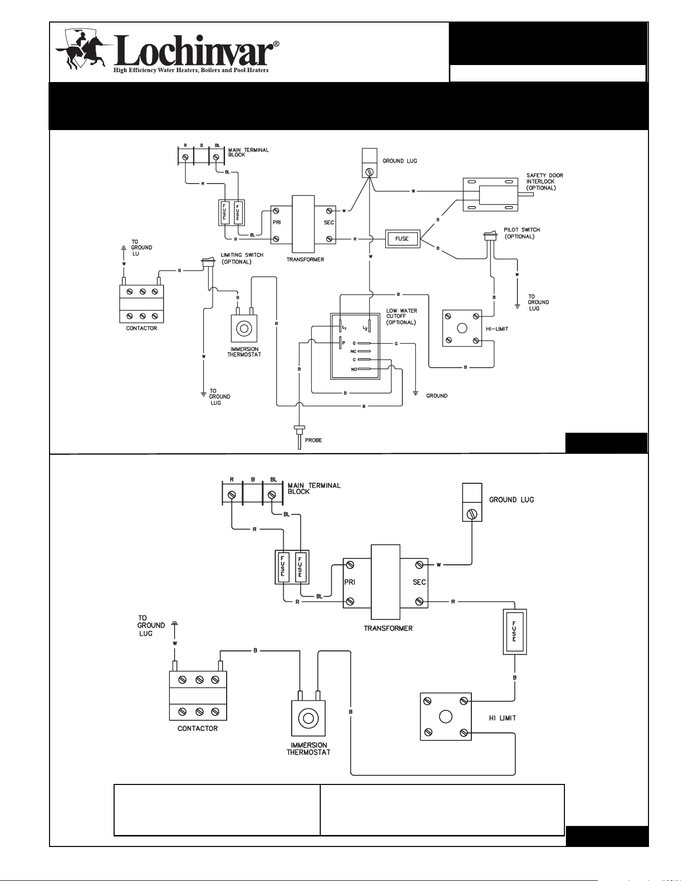
BASIC IMMERSION THERMOSTAT (Control Circuit)
WIRE COLOR CODE
R—Red W—White
B—Black BL—Blue
G—Green
NOTE—Diagrams do not show wiring
from terminal block to fuses, contactors,
and heating elements. Control circuit
only is shown.
IMMERSION THERMOSTAT WITH OPTIONS (Control Circuit)
LIT0716 Rev. A
LIT0717 Rev. A
Wiring Diagrams
CUSTOM HI-POWER
CHP-WI-04
Lochinvar Corporation
Nashville, Tennessee
615-889-8900 Fax: 615-547-1000
www.Lochinvar.com
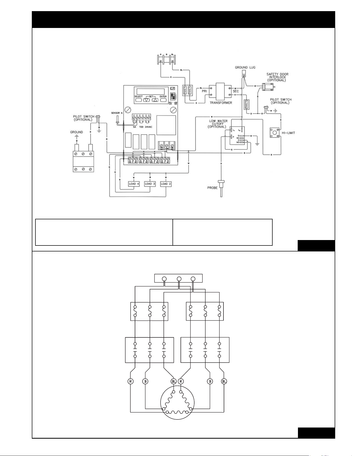
2
CUSTOM HI POWER
®
(CHP) WIRING DIAGRAMS
SOLID STATE STEP CONTROL WITH OPTIONS (Control Circuit)
WIRE COLOR CODE
R—Red W—White
B—Black BL—Blue
NOTE—Diagrams do not show wiring
from terminal block to fuses, contactors,
and heating elements. Control circuit
only is shown.
POWER CIRCUIT (ONE WIRE PER ELEMENT)
MAIN TERMINAL BLOCK
FUSE BLOCKS
CONTACTORS
HEATING ELEMENT
CIRCUIT LIMITED TO 48 AMPS
LIT0709 Rev. A
LIT0712 Rev. A
Power Circuits fused
when total amperage
exceeds 120 amps.
MAIN TERMINAL
BLOCK
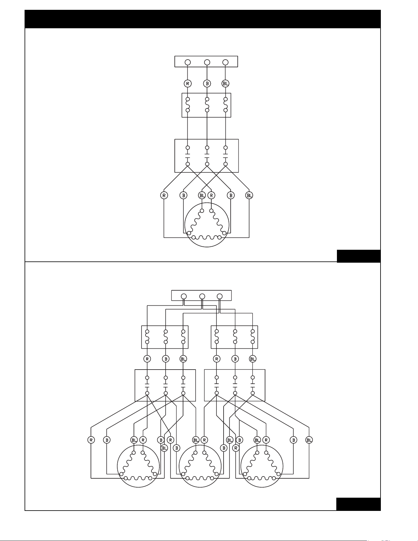
CUSTOM HI POWER
®
(CHP) WIRING DIAGRAMS
POWER CIRCUIT (TWO WIRES PER ELEMENT)
MAIN TERMINAL BLOCK
FUSE BLOCK
CONTACTOR
HEATING ELEMENT
POWER CIRCUIT (THREE WIRES PER ELEMENT)
MAIN TERMINAL BLOCK
FUSE BLOCKS
CONTACTORS
HEATING ELEMENT
CIRCUIT LIMITED TO 48 AMPS
CIRCUIT LIMITED TO 48 AMPS
LIT0713 Rev. A
LIT0714 Rev. A
3
Power Circuits fused
when total amperage
exceeds 120 amps.
Power Circuits fused
when total amperage
exceeds 120 amps.

07/07-Printed in U.S.A.
Lochinvar Corporation
Nashville, Tennessee
615-889-8900 Fax: 615-547-1000
www.Lochinvar.com
150 to 2500 Gallons Storage
Vertical and Horizontal
Energy Saving Performance
Custom Hi-Power
®
Commercial Electric
Water Heaters
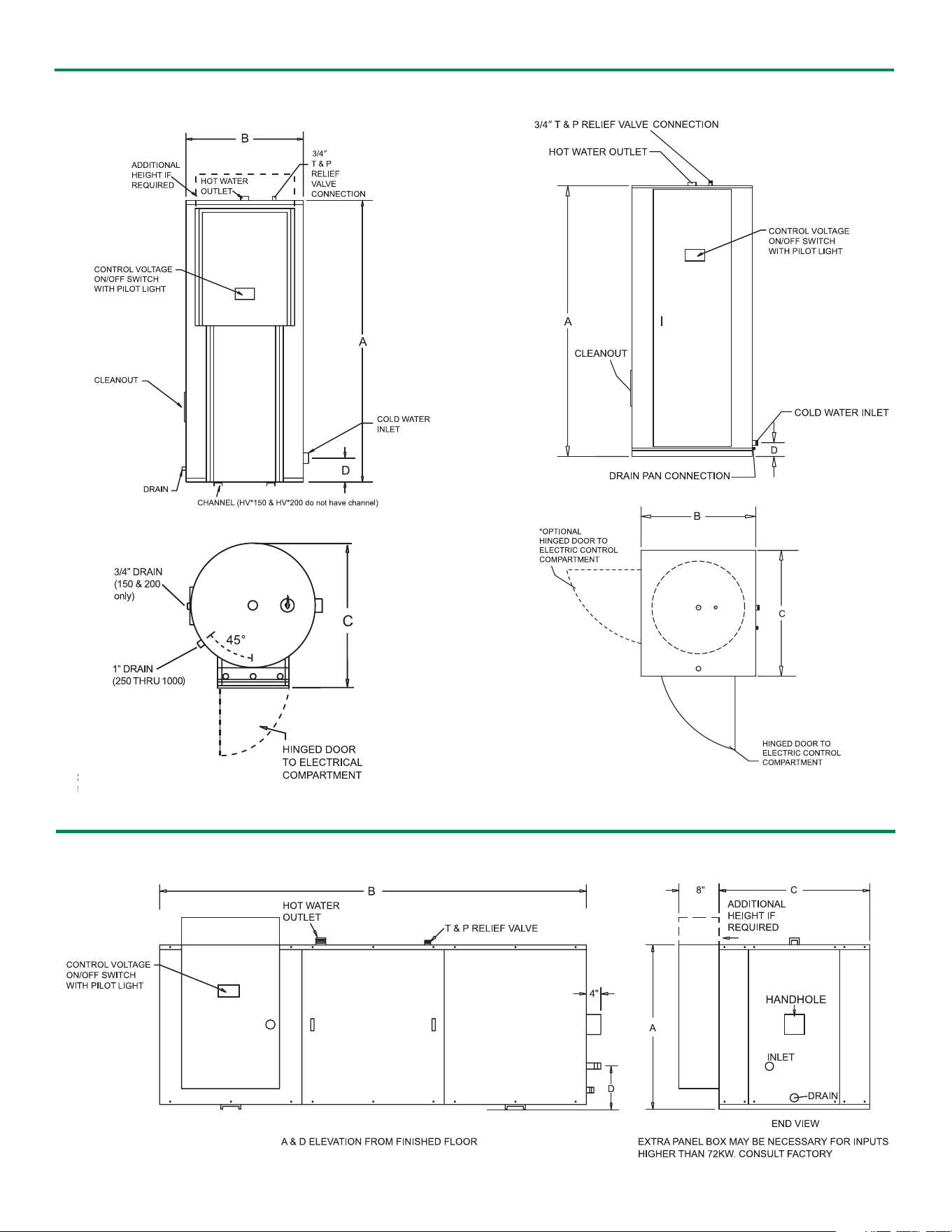
VVeerrttiiccaall RRoouunndd MMooddeellss 115500--11000000
HHoorriizzoonnttaall MMooddeellss
Dimensions
VVeerrttiiccaall SSqquuaarree MMooddeellss 11225500--22550000
TOP VIEW
TOP VIEW
2
*An oversized control panel may be required on models with inputs above 72 kW. An oversized
control panel may increase the width and depth of the square jacket by up to 2”.
Specifications
FOR EASE IN ORDERING
BY MODEL NUMBER
H V X 72 250
VERTICAL
KILOWATT
This unit is a Custom Hi-Power, Vertical, 480 Volt,
Three Phase, 72 Kilowatt, 250 gallon water heater.
HI-POWER
VOLTAGE
GALLON
Max. Gal. Water Shipping
Model KW Cap. A B C D Conn. Weight
Vertical Round Inlet Outlet (.lbs)
HV*kW-150 135 150 65-1/2” 32” 38-3/4” 7-3/4” 1-1/2” 1-1/2” 650
HV*kW-200 180 200 78” 32” 38-3/4” 7-3/4” 1-1/2 ” 1-1/2” 750
HV*kW-250 216 250 92” 34” 40-3/4” 19-1/2” 1-1/2 ” 1-1/2” 1,165
HV*kW-300 270 300 80” 40” 46-3/4” 21” 2” 2” 1,350
HV*kW-400 360 400 80” 46” 52-3/4” 22-1/2” 2” 2” 1,590
HV*kW-500 396 500 92” 46” 52-3/4” 22-1/2” 2” 2” 1,700
HV*kW-600 396 600 92” 52” 60-3/4” 24-1/2” 2-1/2” 2-1/2” 2,010
HV*kW-800 396 750 104” 52” 60-3/4” 24-1/2” 2-1/2” 2-1/2” 2,450
HV*kW-1000 396 950 128” 52” 60-3/4” 24-1/2” 2-1/2” 2-1/2” 3,160
Vertical Square
HV*kW-1250 900 1,250 132-1/2” 64-1/2” 64-1/2” 23-1/4” 3” 3” 3,560
HV*kW-1500 900 1,500 128-1/2” 70-1/2” 70-1/2” 25-1/4” 3” 3” 4,120
HV*kW-2000 900 2,000 140-1/2” 76-1/2” 76-1/2” 27-1/4” 3” 3” 4,350
HV*kW-2500 900 2,500 146-1/2” 82-1/2” 82-1/2” 29” 3” 3” 5,750
Horizontal Square
HH*kW-150 135 150 37” 68-1/2” 34-1/4” 12” 2” 2” 1,180
HH*kW-200 180 200 37” 78” 34-1/4” 12” 2” 2” 1,370
HH*kW-250 225 250 39” 90-1/4” 36-1/4” 13” 2” 2” 1,450
HH*kW-300 270 300 45” 78-1/4” 42-1/4” 14-3/4” 2” 2” 1,530
HH*kW-400 360 400 52” 78-1/4” 48-1/4” 16” 2” 2” 1,750
HH*kW-500 450 500 52” 90-3/4” 48-1/4” 16” 2” 2” 1,860
HH*kW-600 540 600 58” 90-3/4” 54-1/4” 13-1/2” 2-1/2” 2” 2,340
HH*kW-800 720 750 58” 102-1/4” 54-1/4” 13-1/2” 2-1/2” 2” 2,850
HH*kW-1000 900 950 58” 126-1/4” 54-1/4” 13-1/2” 2-1/2” 2” 3,040
HH*kW-1250 900 1,250 64” 130-1/4” 60-1/4” 15” 3” 3” 3,750
HH*kW-1500 900 1,500 70” 126-1/4” 66-1/4” 16” 3” 3” 4,340
HH*kW-2000 900 2,000 76” 137-1/4” 72-1/4” 17-1/2” 3” 3” 4,580
HH*kW-2500 900 2,500 82” 144-1/4” 78-1/4” 16-1/2” 3” 3” 6,060
NOTES: Vertical Round models above 90 kW at 208V, 240V or 380V, and 162 kW at 415V, 480V, or 600V exceed the capacity of a single control
box and may require multiple control panels. Consult the factory for specific details and optional construction.
Vertical Square construction is available as an option for models that exceed the listed kW limits.
Control panel height on Vertical Round models may exceed tank height – consult factory for specific heights on models with inputs above 72 kW.
= Voltage
kW = Kilowatt
J—208V 1ø
K—208V 3ø
A—240V 1ø
B—240V 3ø
W—277V 1ø
*
Y—380V 3ø
Z—415V 3ø
X—480V 3ø
N—600V 3ø
VOLTAGE SCHEDULE
3
Optional Equipment
Lochinvar Corporation • 300 Maddox Simpson Pkwy • Lebanon, TN • 615-889-8900 / Fax: 615-547-1000
www.Lochinvar.com
2/08–Printed in U.S.A.
Standard Features
Standard kW Input & Amperage
CHP-10 (Replaces CHP-09 7/06)
Suggested
GPH@ Max. No. of kW No. of Modulating Amperage Draw
kW 100°F Btu/hr No. of Control Per Contactors Control Steps Single Phase Three Phase
Input Rise Equivalent Elements Steps Element 240/480V 240/480V 208V 240V 208V 240V 480V
12 49 40,944 1 1 12 2/1 - 58 50 33 29 14
15 62 51,180 1 1 15 2/1 - 72 63 42 36 18
18 74 61,416 1 1 18 2/1 - 87 75 50 44 22
30 123 102,360 2 1 15 2/1 - 144 125 83 72 36
36 148 122,832 2 1 18 4/2 4/2 174 150 100 87 44
45 185 153,540 3 1 15 3/2 3/2 216 188 125 108 54
54 221 184,248 3 1 18 6/2 3/2 260 225 150 130 65
60 246 204,720 4 2 15 12/6 4/3 289 250 167 144 72
72 295 245,664 4 2 18 8/4 4/4 - - 200 174 87
90 369 307,080 5 2 18 6/3 3/3 - - 250 217 109
108 443 368,496 6 2 18 12/4 4/4 - - 300 260 130
120 492 409,440 8 3 15 8/4 4/4 - - 333 289 144
135 554 460,620 9 3 15 9/6 4/4 - - 375 325 162
144 590 491,328 8 3 18 16/8 4/4 - - 400 347 174
162 664 552,744 9 3 18 18/6 8/6 - - 450 389 195
180 738 614,160 10 4 18 20/10 8/8 - - 500 434 217
216 886 736,992 12 4 18 24/8 8/8 - - 600 519 260
234 959 798,408 13 5 18 26/13 8/8 - - 650 563 282
252 1,033 859,824 14 5 18 28/14 8/8 - - 700 607 304
270 1,107 921,240 15 5 18 30/10 12/10 - - 750 649 325
288 1,181 982,656 16 6 18 32/16 12/12 - - 800 692 347
306 1,255 1,044,072 17 6 18 34/17 12/12 - - 850 736 368
324 1,328 1,105,488 18 6 18 36/12 12/12 - - 900 780 390
342 1,402 1,166,904 19 7 18 38/19 12/12 - - 950 822 412
360 1,476 1,228,320 20 7 18 40/20 12/12 - - 1,000 865 435
378 1,550 1,289,736 21 7 18 42/14 14/14 - - 1,050 909 455
396 1,624 1,351,152 22 8 18 44/22 15/16 - - 1,100 952 477
414 1,697 1,412,568 23 8 18 46/23 16/16 - - 1,150 995 498
432 1,771 1,473,984 24 8 18 48/16 16/16 - - 1,200 1,040 520
For KW above 432 or other voltages please consult factory
• Glass Lined Steel Tank
• Incoloy Heating Elements
• Internal Fusing (above 120 amps)
• Enamel Finished Galvanized Steel Jacket
• Magnesium Tank Saver Anodes
• Immersion Thermostat
• Manual Reset High Limit
• Full Length Hinged Doors with Key Lock
• Terminal Block Connections
• ASME Temperature and Pressure Relief Valve
(Supplied but not installed)
• Low Water Cut-Off
• Pilot Lights
• Manual Limiting Switches
• Alarm Bell
• Shunt Trip Disconnect (Field Installed)
• Low or High Water Pressure Switch
• Lifting Lugs
• Time Clock (7 day or 24 hour)
• Channel Iron Skid Base (Except 150 & 200 gallon round)
• Approved for 180°F Temperature Operation
• ASME Construction and National Board Listed
• All models meet or exceed ASHRAE
energy efficiency standards
• 125 psi Working Pressure
• Handhole/Cleanout
• UL Listed (U.S. and Canada)
• Safety Drain Pan (Square Models)
• 3 Year Limited Tank Warranty
• Control Voltage On/Off Switch w/ Pilot Light
• BMS Enable/Disable Contacts
• Safety Door Interlock
• Temperature and Pressure Gauges
• Manway (250 Gallon and Larger Only)
• 150 psi or 160 psi Working Pressure
• Electronic Step Controller
• Seismic Attachment Points (250 Gallon and Larger Only)
(customer must provide seismic zone or city and state of install)