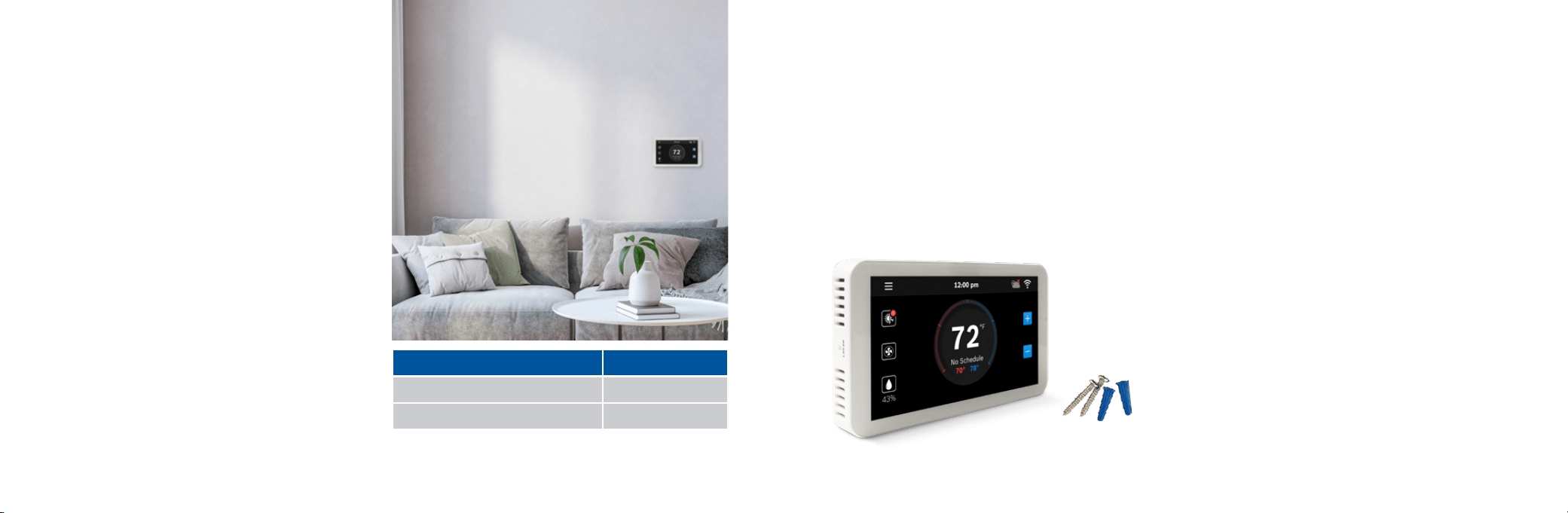
Smart Home Control SHC350 Wi-Fi Thermostat
Installation Guide & User Manual
Get The Most
Out of Your New
Thermostat
Download The
GoTemp Home App
2 3
Compatibility
Thermostat Installation
Initial Setup
Advanced Settings
Troubleshooting
Wiring Diagrams
4
6
11
20
23
25
Table of Contents
Thermostat Main Screen
Icons
Temperature Setpoints
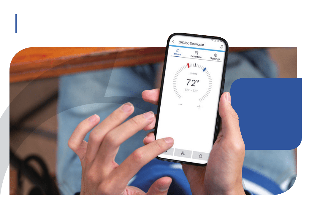
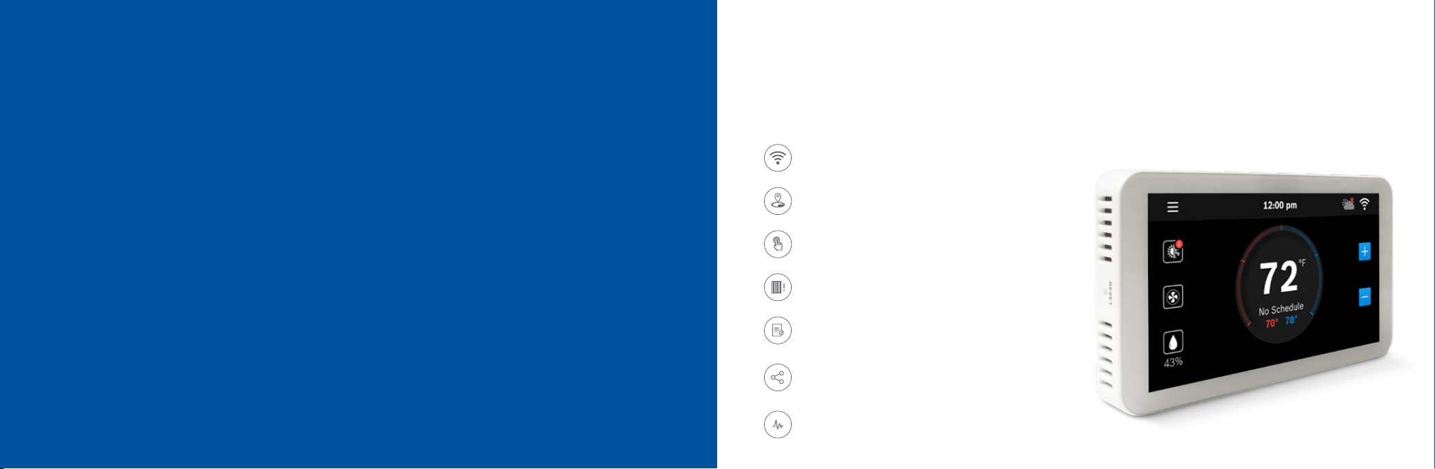
The Smart Home Control SHC350 Thermostat is compatible with the majority of 24V heating and cooling equipment to
help you save energy and money. Easily control your home's temperature from the full color 5” touchscreen display, the
GoTemp Home App or your voice with the Smart Home Control Alexa Smart Home Skill and your Alexa-enabled smart
devices or with Google Assistant.
Connectivity
Connect to your HVAC equipment from anywhere
Programmable
Follows preset or user-defined schedules
Compatibility
Compatible with majority of HVAC systems
(requires C-wire)
Enabled Smart Devices Compatible
Works with Google Assistant or Amazon Alexa
HVAC Filter Reminder
Get alerts when its time to replace your system's filter
Meet the Smart Home Control (SHC350 Thermostat)
Installation Guide SHC350 Device User Manual
31
32
34
GoTemp Home App User Manual
Additional Features
GoTemp Home App
App Main Screen Overview
Setpoint(s) on the App
Schedule Overview
Alexa
Google Assistant
Warranty & Legal
35
35
36
37
Thermostat Overview
Unit Operating Mode
Fan
Accessory
Additional Information
39
40
41
42
44
44
44
App Menu Overview
Mode
Device Messages
Temperature
46
48
50
2
Weather
Access your local forecast from your thermostat
5” Full-Color Touch Screen
Large screen for ease-of-use and offline access
4 5
Compatibility
XA C-wire (common wire) is required to power the
unit Two wire systems are not supported. If a C-wire
is not readily available, we recommend you seek
professional support from your local contractor.
XThe Smart Home Control SHC350 Wi-Fi Thermostat
works with most 24V systems, including gas, oil,
propane, electric, forced air, variable speed, heat
pump and radiant.
XFor conventional (gas/oil/electric): Heat Only, Cool
Only,and Combined Heat & Cool. For heat-pump
systems: Up To 4-Heat & 2-Cool.
The thermostat cannot support
XLine voltage thermostats
XElectric baseboard heaters
XProprietary communicating thermostats
XMillivolt systems
XRemote sensors
Professional installation is recommended
for the following systems
XDual Fuel systems (Heat Pump combined with a Furnace)
XWhole-home humidifiers and dehumidifiers
Included in the box
X SHC350 Wi-Fi Thermostat
X Screws (2) and Anchors (2)
X Flathead Screwdriver
X Wire Labels
X Jumper Wire
X User Guide
X Customer Support Card
Tools you will need
X Medium Phillips screwdriver
(for attaching the Wall Plate to the wall)
X Smartphone
(for taking pictures of the existing wiring)
X GoTemp Home App
(For registering your device)
Tools you may need
X Needle-Nose Pliers (for pulling wires from the wall)
X Drill with 7/32” Drill Bit (for mounting wall anchors)
X Wire Stripper (for cutting and stripping wires)
X Multimeter (for testing circuit power and continuity)
X Pen or Pencil (for preventing wires from falling into the wall)
Installation Overview
Once you have everything you need, let’s get started!
Thermostat Model Part Number
SHC350 Thermostat S1-TSHC350
Wall Plate, Screws & Wall Anchors S1-8733948984
6 7
Thermostat Installation
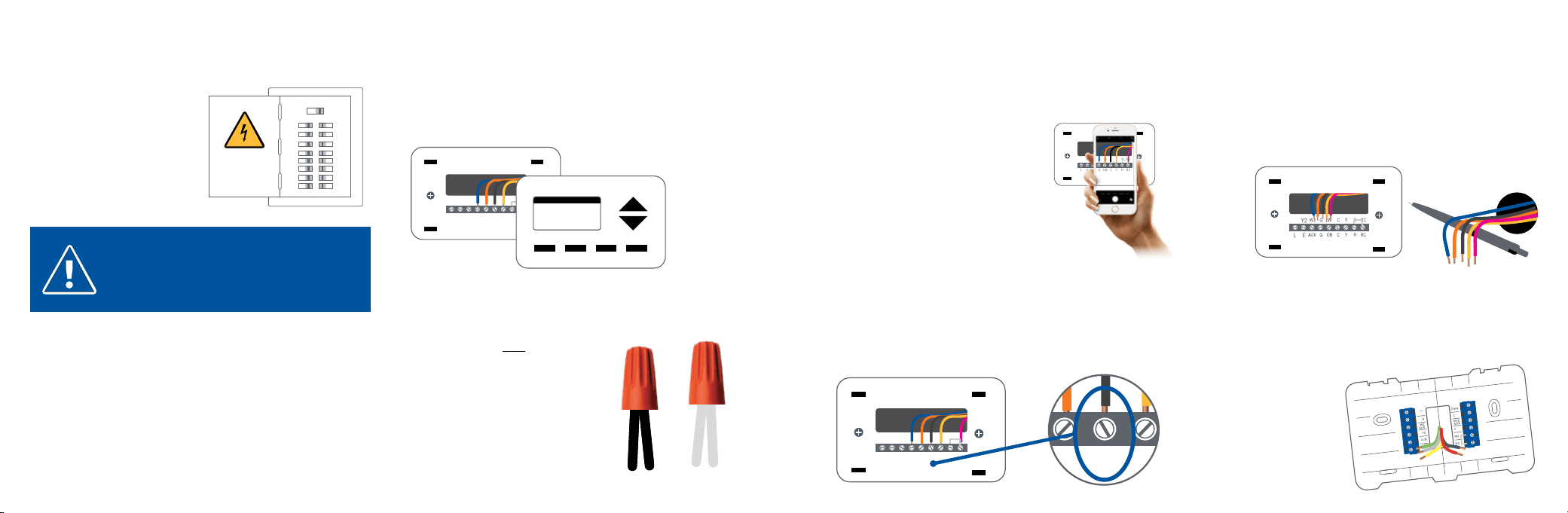
Turn OFF power
Turn off all power to your HVAC
(Heating, Ventilation, and Air
Conditioning) system by using the
master equipment switch or
circuit breaker box.
Confirm that your system is off
One way to do this is to try to adjust the temperature on your old
thermostat. If you don’t hear the system turn on within 5
minutes, air does not come out from the vents or the old
thermostat does not even power on, then you have successfully
turned off the power to your system.
Step 1 Step 2
Make sure your old
thermostat Does Not
Contain Line Voltage Wiring
If you see any of these wire nuts,
unfortunately the SHC350 may not
work with your system. If you are
unsure or would like to discuss your
options, please contact a professional.
Step 3
WARNING: Failure to turn off the power may result in
electrical shock and/or damage to the equipment.
Remove the old thermostat from the
old wall plate
Take a picture of the existing wiring
Make sure that you can clearly read the terminal labels and see
which wires are connected to which terminals from your photo.
You will need to reference this photo later
during the initial setup.
Note: You can also use the wire labels
we have provided you to correctly label
each wire based on the terminal where it
is connected.
Step 4
ON OFF
Y2 W2 G W C Y R RC
EL
AUX
G OB C Y R RC
OLD WALL PLATE
OLD THERMOSTAT
Y2 W2 G W C Y R RC
EL
AUX
G OB C Y R RC
Confirm you have a C-wire connected
to your old thermostat wall plate
If you do not have a C-wire connected to your old thermostat,
please contact a professional for further assistance to determine
if the SHC350 Thermostat is compatible with your system.
Step 5
Y2 W2 G W C Y R RC
EL
AUX
G OB C Y R RC
Y2 W2 G W C Y R RC
EL G OB C Y R RC
Disconnect the wires from the old thermostat and
remove the wall plate using a screwdriver
Some thermostats will also require you to use a screwdriver to
disconnect the wires. After the wires are disconnected and the wall
plate removed, we recommend wrapping a pen or pencil around the
wires to prevent them from falling back into the wall.
Step 6
Step 7
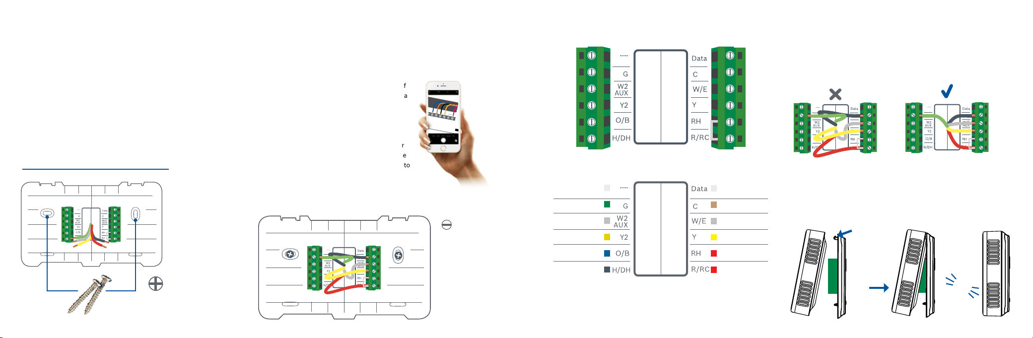
Pull thermostat wires through the hole in the center
of the SHC350 wall plate and mark the location of
the mounting screws
It is recommended to use the SHC350 Wall Plate as a reference guide
to mark the mounting holes and ensure that all holes and
unpainted surfaces are
covered.
8 9
Drill and insert wall anchors (if necessary)
Drill two 7/32” holes where you marked the location of the mounting
screws and then insert the wall anchors provided into these mounting
holes.
Check if the wall plate is level and insert screws
Make sure your new SHC350 wall plate is level and insert the included
screws from the package. Mount your new wall plate to the wall using a
Phillips head screw driver.
Step 8
Insert each wire into the corresponding
terminal and close each terminal using a
flat head screw driver
Use the image you took with your smartphone of
your old thermostat wiring or the wire labels as a
reference for where to place each wire. Be sure
that you insert each wire, one by one, and then
immediately close the terminal and confirm that
the wire is secure inside the terminal before
moving to the next wire. Repeat this process for
each wire to be installed. If you are unsure of the
terminal names on the SHC350 Wall Plate, refer to
SHC350 Terminal Key on the next page.
Step 9
SHC350 Terminal
After all wires are securely connected,
gently push any excess wires back into
the hole in the wall
Step 10
Attach the SHC350 Thermostat
to the SHC350 wall plate
Step 11
PUSH
HOOK
CLICK
SMALL
FLAT HEAD
SCREWDRIVER
NEEDED
PHILLIPS HEAD
SCREWDRIVER NEEDED
Thermostat Installation
LEVEL
Alarm Input
3
C-wire (common)
1st Stage Heating
1
1st Stage Compressor
Heating Appliance Power
Thermostat Power/
Cooling Appliance Power
Not Used
Fan
(W2) 2nd Stage Heating
2
2nd Stage Compressor
2nd Stage Heating
Humidifier/Dehumidifier
Reversing Valve
Note: The color of your wires may not be the same as shown
(1)Emergency Heat activated at W/E,
(2)Single-stage Auxiliary heat activated at W2/AUX,
(3)With compatible WSHP
R/RC
10 11
Step 12 Step 13
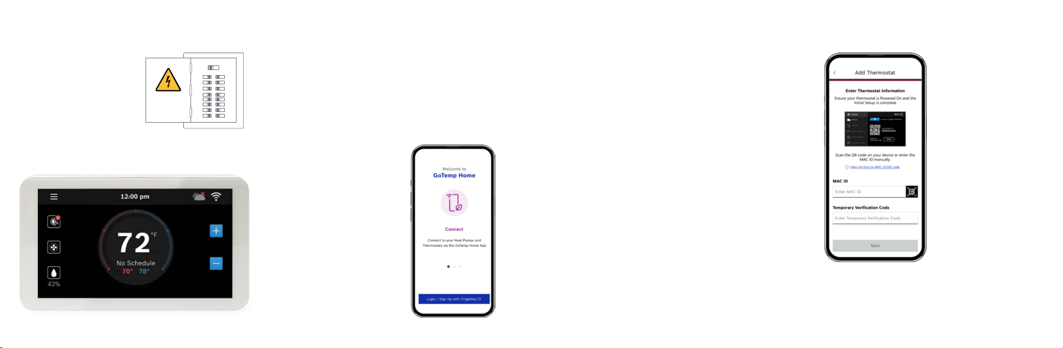
Turn ON the power to your
HVAC by using the master
equipment switch or circuit
breaker box
The thermostat will power on and
display a brand selection screen.
After selecting your appliance brand,
there will be a brand logo and loading bar.
Note: After loading completes, the
thermostat will display the following screen:
ON OFF
Great job, the hard part’s over!
Next, get your smartphone and visit your app
store. Download the GoTemp Home App to
setup your new SHC350
Your SHC350 Thermostat is not yet configured to your home’s HVAC
system. Go to the Apple App Store or Google Play Store to download
the app, create an account, and finish configuring your system.
Three ways to download
the GoTemp Home App:
XIn the Apple App Store
or Google Play, search
GoTemp Home and then
download the app.
Initial Setup
User Account Setup
1. After downloading the GoTemp Home App, open the app on your
smartphone and accept the terms and conditions
2. Enter an e-mail address and password with which you would like to
register.
3. To begin creating your profile, select your role as “Homeowner”.
4. Input your first and last name.
5. Verify phone number by entering the phone verification code you receive
via text.
6. Your profile has been successfully created.
Add Device
1. After successfully creating your profile, choose the Appliance you
would like to add, in this case SHC350.
2. Return to your thermostat and click Ok to initiate the Initial Setup.
3. Follow the on-screen instructions to name your thermostat and
connect your smartphone to the device.
4. Follow the on-screen instructions to name your thermostat and
connect your smartphone to the device.
Thermostat Installation
MAC ID and Temporary
Verification Code
You can find the MAC ID and Temporary Verification Code by
navigating to the Wi-Fi Settings screen on your thermostat
and clicking the Registration button.
12 13
Initial Setup
If you have a dual fuel system
1.
Select Dual Fuel and click the Next Arrow at the
top right corner of the screen.
2. Then follow the on-screen instructions to configure the fossil
fuel fan control settings
3. Click Next Arrow at the top right corner of the screen.
Then follow the on-screen instructions to configure
the heat pump dual fuel changeover settings.
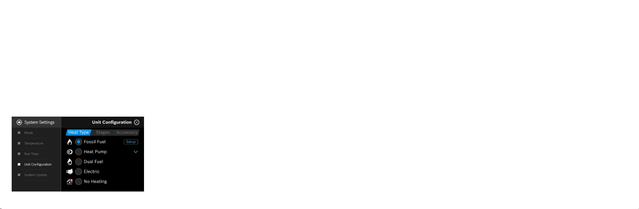
If you have a furnace
1.
Select Fossil Fuel and click the Next Arrow at the top right
corner of the screen.
2. Then select Appliance or Thermostat depending on your
personal preferences for fan control.
3. Click Next Arrow at the top right corner of the screen.
If you have a heat pump
1.
Select Heat Pump and click the Next Arrow at the top right
corner of the screen.
2. Then follow the on-screen instructions.
3. Click Next Arrow at the top right corner of the screen.
4. Configure the reversing valve for O (energized in cool)
or B (energized in heat) and enable/disable Emergency
Heat and/or Auxiliary Heat.
If you have a boiler
1.
Select Fossil Fuel and click the Next Arrow at the top right
corner of the screen.
2. Then select Appliance
3. Click Next Arrow at the top right corner of the screen.
Unit Configuration
Select your home’s heating type, stage configuration for heating and
cooling, and type of accessory (humidifier or dehumidifier) if available.
Select your heat type
Select your Heat Type according to the heating appliance located in your
home. Below is a list of helpful tips that may guide you to selecting the
correct option for your home.
Note: If you are unsure of which option to select,
contact your local contractor.
If you have an electric system
Select Electric and click Next Arrow at the top right
corner of the screen
If you have no heating appliance
Select No Heating and click Next Arrow at the top right
corner of the screen
Select your stage configuration
Select your stage configuration according to the heating
and cooling appliances you have in your home and
then click Next Arrow at the top right corner of the screen.
4. Use the Balance Point to set the outdoor temperature value the
thermostat will use to switch between your heat pump and fossil
fuel appliance. Above this value, your thermostat will use your
heat pump to heat your home and below this value, your
thermostat will use your fossil fuel heating appliance.
5. Use the Change over Delay to set the time the system will be off
when changing between heat pump and fossil fuel heating
sources. This delay allows for the coil to cool before switching
between heating appliances.
Note: In a dual fuel system, the SHC350 automatically enables
auxiliary heating using the fossil fuel heating appliance.
Note: In a dual fuel system, the SHC350 will stage up from
heat pump to fossil fuel following the stage settings, which can
be modified in Advanced Settings > Installer Access > by using
the ST Action Code.
6. Click Next Arrow at the top right corner of the screen.
If you have a whole home humidifier or dehumidifier
accessory wired to your thermostat, select the type of
accessory you have in your home; otherwise, click None
and then click Next Arrow.
Note: Professional installation is recommended for humidifiers and
dehumidifiers.
If you have a Humidifier
1.
Select Humidifier and click the Next Arrow at the top right corner of
the screen.
2. Then select Evaporative or Steam following the on-screen
instructions. For Evaporative the humidifier is activated only during
active heating. For Steam the humidifier is activated regardless of a
heating call.
3. Click Next Arrow at the top right corner of the screen.
If you have a Dehumidifier
1.
Select Dehumidifier and click the Next Arrow at the top right corner
of the screen.
2. Then enable or disable Cool to Dehumidify following the on-screen
instructions. If Cool to Dehumidify is enabled the dehumidifier is
activated only during active cooling. If disabled the dehumidifier is
activated regardless of a cooling call.
3. Click Next Arrow at the top right corner of the screen.
Need Help?
If you are unsure of which option to select,
contact your local contractor.
For a quick and easy way to begin using your new smart thermostat,
the device will automatically direct you to the Initial Setup screen after
you have turned it on for the first time.
14
Initial Setup
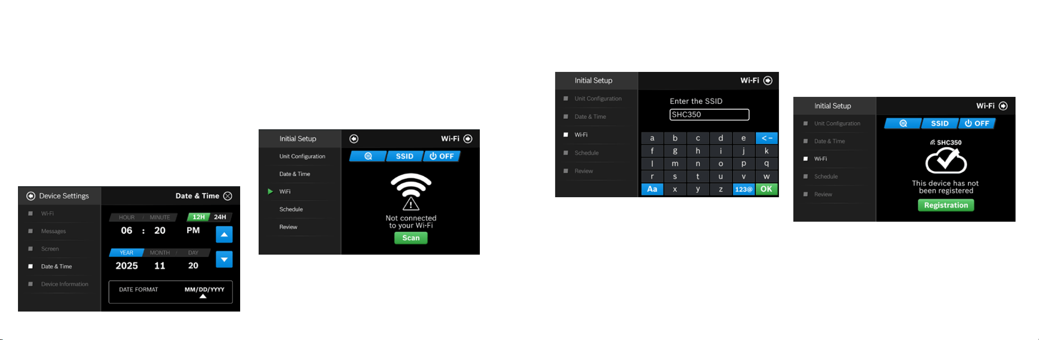
Date & Time
Follow the on-screen instructions to set the date and time of
SHC350 Thermostat and then click Next Arrow at the top right
corner of the screen.
On Device
Enter your location’s current date and time; after the device is
registered or linked to a user account, the date and time on the
device will automatically update to the current time associated
with the user account.
App
The date and time for the device, as well as the user account,
will automatically update by selecting the time zone for the device.
Wi-Fi
The SHC350 requires a reliable Wi-Fi connetion in order to access
smart features such as remote access, weather forecast and more.
To complete the Wi-Fi setup, follow the on-screen instructions.
Scan
To start Wi-Fi setup, click the Scan icon to view available
Wi-Fi networks. Follow the on-screen instructions to complete
the Wi-Fi setup.
Manual Entry
If you are trying to connect to a hidden network, press the SSID
button to bring up the SSID screen. Enter your SSID into the text box,
then follow the on-screen instruction to complete the Wi-Fi setup.
Note: If this is a first time installation, follow the instructions in the
App Setup section of this User Guide to register your thermostat to
your smart device.
The following may cause a failed connection to the device:
X Wi-Fi signal is too weak
X 5 GHz Wi-Fi network is not supported
X SSID contains space or non-ASCII characters
X Incorrect password
X Wi-Fi is okay but your internet is unavailable
X Additional web authentication is not supported
After you have successfully established a connection, your network
name appears. If your thermostat is already registered to your account
on your smart device, your User ID name appears. Follow additional
instructions on the screen to complete setup. After completing the
setup, download the GoTemp Home App from the Apple Store or Google
Play Store. Create an account within the app and then add a device
(SHC350) by following the on-screen instructions.
Note: For all smart devices that require access to the same
thermostat, you must use the same account.
15
16 17
Schedule
Choose the schedule you would like to modify, or select No Schedule if
you do not wish to set up a schedule at this time, and click the Setup
button or Next arrow.
Note: Home is the default schedule for your SHC350. If you wish to
add a different schedule, use the GoTemp Home App.
To set up your periods for the day, click on the Start Time bubble of the
period and use the Up/Down arrows to set the start time of the first
period of the day.
1. Next, click the Heat bubble and use the Up/Down arrows to set the
heating setpoint for the first period of the day.
2. Then, click the Cool bubble and use the Up/Down arrows to set the
cooling setpoint for the first period of the day.
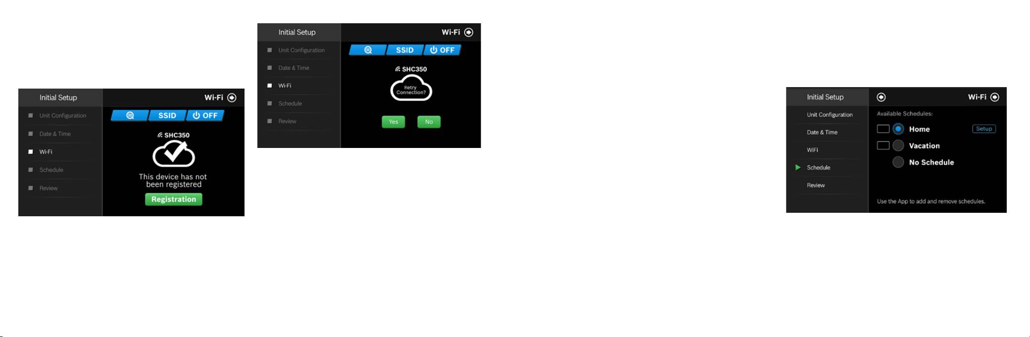
For an unregistered device, click the green Registration button to
register your account. If you want to register a different account to your
device, you can also click the Registration button and follow the steps
outlined in the App Setup section of this User Guide.
Auto Reconnect
If your device loses connection with your wireless network, it will
automatically attempt to reconnect after 5 minutes. If that fails, it
will make a new attempt every 15 minutes for the next 24 hours.
Any manual network reconfiguration of the thermostat will stop
automatic reconnection attempts.
Initial Setup
Note: There is a 5 degree deadband required between heating
and cooling setpoints to prevent equipment from short cycling.
3. If you want to add more periods, then click add period button and
repeat the above 3 steps until you have set all your periods for the
day.
Note: You are allowed a maximum of 8 periods per day.
4. If you want to delete a period, select any bubble corresponding to
that period and click Delete.
5. After you have set up one day of the week, use the Copy section to
mirror the same daily schedule to other days of the week by clicking
on the days you would like to copy that daily set of periods. Then
click next.
Note: If you have not copied your schedule to all 7 days of the
week, you will be required to repeat the above steps until you
have set a schedule for everyday of the week.
On Device
During offline operations, only 2 schedules (Home and Vacation)
are available. However, when a Wi-Fi connection is established,
the list can be expanded up to 4 schedules.
Home
You can use this schedule to set your heating/cooling equipment to
predefined set points. The device initially comes with a factory default
schedule, which can be adjusted as necessary.
Vacation
This schedule will be used to set your heating/cooling equipment
to 2 periods with set points (1 heating and 1 cooling) that can be
manually adjusted. However, you will not be able to add additional
or remove current periods. The schedule can be used for vacation
or permanently setting a heating/cooling set point.
18
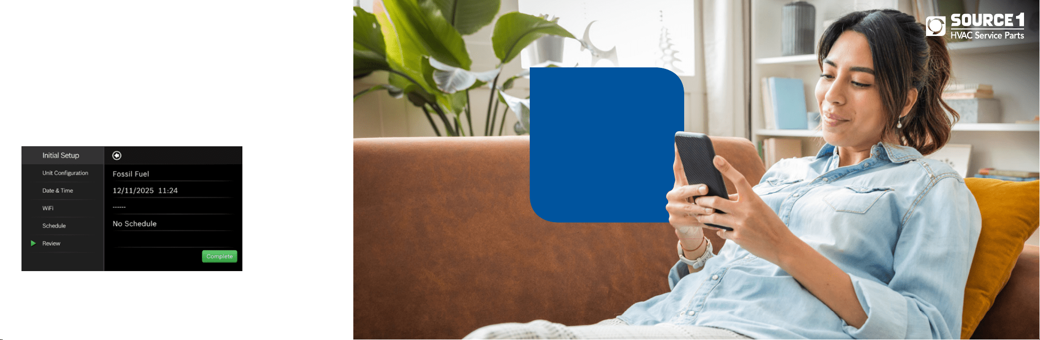
Review
In the final step, the SHC350 provides a summary review of
information that you have entered into the thermostat. You will
be able to go back to different parts of the Initial Setup guide by
pressing the different sections on the left pane or using the
Previous arrow. If you have completed the review, please press
the Complete button to start utilizing your SHC350!
Initial Setup
19
Congratulations!
You have finished the
installation and setup of
your SHC350 Thermostat.
Thank you for choosing
the SHC350 and enjoy the
savings and comfort of
owning your Smart Home
Control thermostat!

2120
Advanced Settings allow HVAC professionals the ability to modify specific thermostat settings for better control of the heating and
cooling appliance(s). In order to access the Advanced Settings of the SHC350 Thermostat, your thermostat must be connected to
Wi-Fi. The Advanced Settings section is accessible from the Menu of the SHC350 Thermostat.
FOR CONTRACTORS ONLY: Advanced Settings are for professional use only and require an access code
ACCESS CODE: 1886
Advanced Settings
Heating & Cooling
X To access the Heating and Cooling, select Advanced Settings from the Menu, then select Heating and Cooling.
X Enter the Professional Access Code and select a parameter to modify the default value. From this menu you can adjust:
Title Default Max Min Description
Fan Delay On 0 Seconds
120 Sec-
onds
0 Seconds
The fan’s lag time after the heating or cooling call is initiated when in Fossil Fuel,
Heat Pump, or Cooling operation.
Fan Delay On
Elec
0 Seconds 5 Seconds 0 Seconds
The fan’s lag time after the heating or cooling call is initiated when in Electric,
Auxiliary heat, or Emergency heat operation.
Fan Delay Off
60 Sec-
onds
120 Sec-
onds
30 Sec-
onds
The fan’s lag time after the heating or cooling call is terminated.
Min. Run Time 5 Minutes
Stage
Delay
3 Minutes
The minimum amount of time a heating or cooling call will run after the initial call.
This timer resets and must be met after each stage up condition.
Anti Short Cycle 5 Minutes 5 Minutes 0 Minutes
The minimum amount of time a heating or cooling call will run after a stage down
condition. This timer resets and must be met after each stage down condition.
Cycle Time
180 Sec-
onds
300 Sec-
onds
60 Sec-
onds
Time delay required between system mode changes before active heating or
cooling calls can begin.
Zero Energy
Band Heating
1° F/
0.5° C
2° F/ 1° C
0.5° F/
0.3° C
A temperature range between the current temperature and the heating set point,
where heating is not engaged.
Zero Energy
Band Cooling
1° F/
0.5° C
2° F/ 1° C
0.5° F/
0.3° C
A temperature range between the current temperature and the cooling set point,
where cooling is not engaged.
Deadband 5°F/3°C 9°F/5°C 2°F/1°C
A temperature range between the heating set point and cooling set point in
Auto Mode, where heating/cooling is not engaged.
Installer Access
X To access the Installer Access,click Advanced Settings, enter the Professional Access Code and click Installer
X Enter any one of the Action Codes in parenthesis below to gain access to that specific setting:
Humidity Calibration (HC): Ability to adjust humidity readings after extended product use.
Relative Humidity Hysteresis (HSD): Adjust the set point differential for the humidity control.
Initial Setup (IS): Initial Setup process.
Sensor Calibration (SC): Ability to adjust temperature readings after extended use.
Sensitivity Level (SS): The lower the level, the more your system cycles to maintain the set point(s).
Staging (ST): Configuration options: Latching, Stage Delay and Stage Temp.
Electric Heat Kit (EHK): Ability to adjust the W hysteresis and EHK stage delay
Advanced Settings
2120

22 23
Troubleshooting & Frequently Asked Questions
Wi-Fi
Can the SHC350 be used without Wi-Fi?
We strongly encourage everyone to use the Wi-Fi capabilities of the thermostat, as it will improve the user experience. However, it is
functional without the use of Wi-Fi after the Initial Setup has been completed.
NOTE: The Dual Fuel feature is disabled when Wi-Fi is unavailable. Dual fuel requires Wi-Fi to determine outdoor air temperature
and function properly.
Will the SHC350 support all Wi-Fi systems & routers?
This device only works with 2.4 GHz systems and is NOT compatible with 5.0 GHz systems or web pages that require additional web
authentication.
Trouble Connecting to your Home's Wi-Fi Network?
1.
Make sure that your thermostat is a maximum 20 ft or less from the router/modem without any obstructions (i.e. walls,
floors, ceilings, etc.). If obstructions exist, try moving your thermostat and router/modem closer together.
2. Before attempting to reconnect your thermostat to your home network, power cycle your router/modem and then your thermostat.
If you have a separate router and modem, make sure that you power cycle the modem first and then the router.
3. In the event that you still cannot connect to your home’s wi-fi network please contact our support team for further
in-depth technical troubleshooting options.
NOTE: If you are able to connect to your home network, but the time does not update on the thermostat, you are not fully
connected to the cloud server. Please follow the troubleshooting steps again or contact your installing contractor.
GoTemp Home App (Android and iOS)
What is the name of the smartphone app in the App Store and Google Play Store?
The name of the app is GoTemp Home App.
How many accounts can be associated with the thermostat at once?
Only one account can be associated with a given thermostat. Family members must share their account
information with each other if they would like to be able to control the thermostat from multiple devices.
Can this device be accessed via a web page?
Not at this time.
Thermostat
What happens if I lose power to the device; will all my settings be lost?
All settings are kept in local memory, except for the schedule setpoints, which are stored in the cloud.
Therefore, all settings will be saved even during a power outage.
SHC350 and GoTemp Home App Support
For support regarding the SHC350 and GoTemp Home App, contact:
- 1-800-283-3787
Troubleshooting & Frequently Asked Questions
24 25
Wiring Diagrams
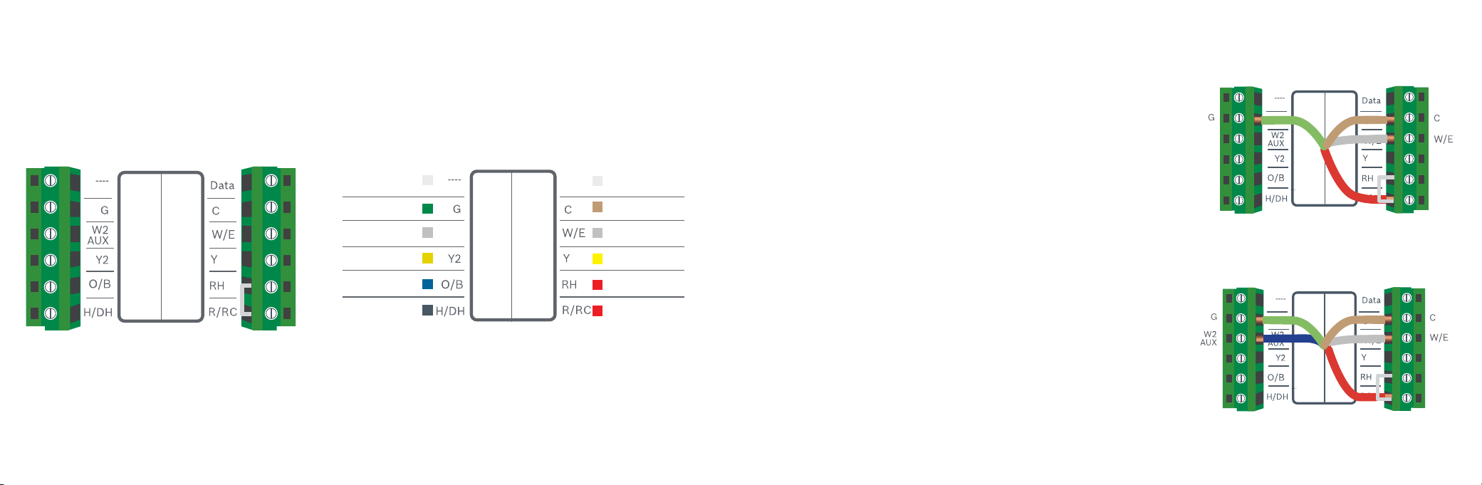
Single Stage Heat – Furnace
Example: 80% AFUE Gas Furnace
▶ Ensure the system has a C-wire
▶ Ensure the pre-installed jumper wire remains between RH and RC
▶ Connect the R, C, W1 and G wires from the Furnace to R/RC, C,
W/E and G terminals on the wall plate, respectively
Two Stage Heat – Furnace
Example: 96% AFUE Gas Furnace
▶ Ensure the system has a C-wire
▶ Ensure the pre-installed jumper wire remains between RH and R/RC
▶ Connect the R, C, W1, W2 and G wires from the Furnace to R/RC, C,
W/E, W2/AUX and G terminals on the wall plate, respectively
R/RC
R/RC
SHC350 Terminal
SHC350 Terminal Key
Alarm Input
3
C-wire (common)
1st Stage Heating
1
1st Stage Compressor
Heating Appliance Power
Thermostat Power/
Cooling Appliance Power
Not Used
Fan
(W2) 2nd Stage Heating
2
2nd Stage Compressor
2nd Stage Heating
Humidifier/Dehumidifier
Reversing Valve
Data
W2
AUX
Wiring Diagrams
Note: The color of your wires may not be the same as shown
(1)Emergency Heat activated at W/E,
(2)Single-stage Auxiliary heat activated at W2/AUX,
(3)With compatible WSHP
26 27
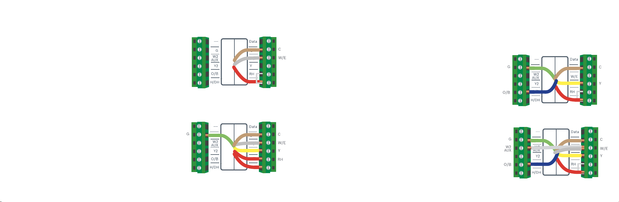
Single Stage Heat – Boiler
Example: Greenstar Gas Condensing Boilers*
▶ Ensure the system has a C-wire
▶ Ensure the pre-installed jumper wire remains between RH and RC
▶ Remove the jumper from the thermostat connection on the boiler and
connect the two terminals to RH and W/E on the thermostat.
▶ *NOTE: Greenstar boilers will require an external transformer to power the thermostat.
The two power wire should connect to R/RC and C on the Thermostat.
Combined Single Stage Heat Furnace and
Single Stage Cool Air Conditioner
fEnsure the system has a C-wire
fRemove the pre-installed jumper wire from between RH and R/RC
fConnect the R, C, W1 and G wires from the Furnace to RH, C,
W/E and G terminals on the wall plate, respectively
fConnect the R, C, Y1 and G wires from the Air Conditioner to R/RC,
C, Y and G terminals on the wall plate, respectively
Wiring Diagrams
R/RC
R/RC
Single Stage Heat Pump
▶ Ensure the system has a C-wire
▶ Ensure the pre-installed jumper wire remains between RH and R/RC
▶ Connect the R, C, Y1, O/B and G wires from the heat pump to R/RC, C, Y,
O/B and G terminals on the wall plate, respectively
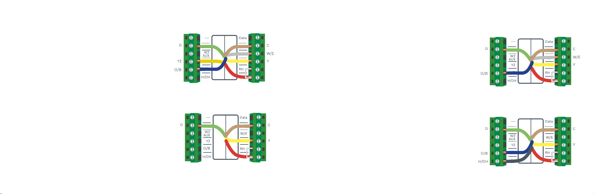
Single Stage Heat Pump
with Emergency Heat and Auxiliary Heat
Note: W/E controls Emergency Heat output, and W2/AUX controls
Auxiliary Heat output.
▶ Ensure the system has a C-wire
▶ Ensure the pre-installed jumper wire remains between RH and R/RC
▶ Connect the R, C, W1, Y1, O/B and G wires from the heat pump to R/RC,
C, W/E, Y, O/B and G terminals on the wall plate, respectively
▶ Connect jumper wire between W/E and W2/AUX.
Wiring Diagrams
R/RC
R/RC
R/RC
R/RC
Heat pump systems
Heat pump systems are specialty designed to be able to provide heating and
cooling using a single compressor, a reversing valve, and a fan.
28 29
Two Stage Heat Pump
with One Stage Emergency Heat
▶ Ensure the system has a C-wire
▶ Ensure the pre-installed jumper wire remains between RH and R/RC
▶ Connect the R, C, W1, Y1, Y2, O/B and G wires from the heat
pump to R/RC, C, W/E, Y, Y2, O/B and G terminals
on the wall plate, respectively
Single Stage Cool – Air Conditioner
▶ Ensure the system has a C-wire
▶ Ensure the pre-installed jumper wire remains between RH and R/RC
▶ Connect the R, C, Y1 and G wires from the Air Conditioner to R/RC, C, Y
and G terminals on the wall plate, respectively
Wiring Diagrams
R/RC
R/RC
Combined Single Stage Heat Pump and Single
Stage Furnace (Dual Fuel)
▶ Ensure the system has a C-wire
▶ Ensure the pre-installed jumper wire remains between RH and R/RC
▶ Connect the R, C, W1 and G wires from the Furnace to R/RC, C,
W/E and G terminals on the wall plate, respectively
▶ Connect the C, Y1, G, and O/B wires from the Heat Pump to
C, Y, G, and O/B terminals on the wall plate, respectively
Humidifier or Dehumidifier Accessory
with a Single Stage Heat Pump
A single Humidifier or Dehumidifier Accessory can be controlled using the SHC350.
The thermostat only supports Humidifiers in heating operation, Dehumidifiers in
cooling operation, and only one accessory per thermostat.
Note: The wiring configuration for humidifiers and dehumidifiers is the same
for all type of Systems. The thermostat does not provide power to the
accessory; only control.
▶ Ensure that the accessory is externally powered
▶ Ensure the Heat Pump System is wired correctly
▶ Connect the control wire of the accessory to the H/DH
terminal of the wall plate
Wiring Diagrams
R/RC
R/RC
30 3130
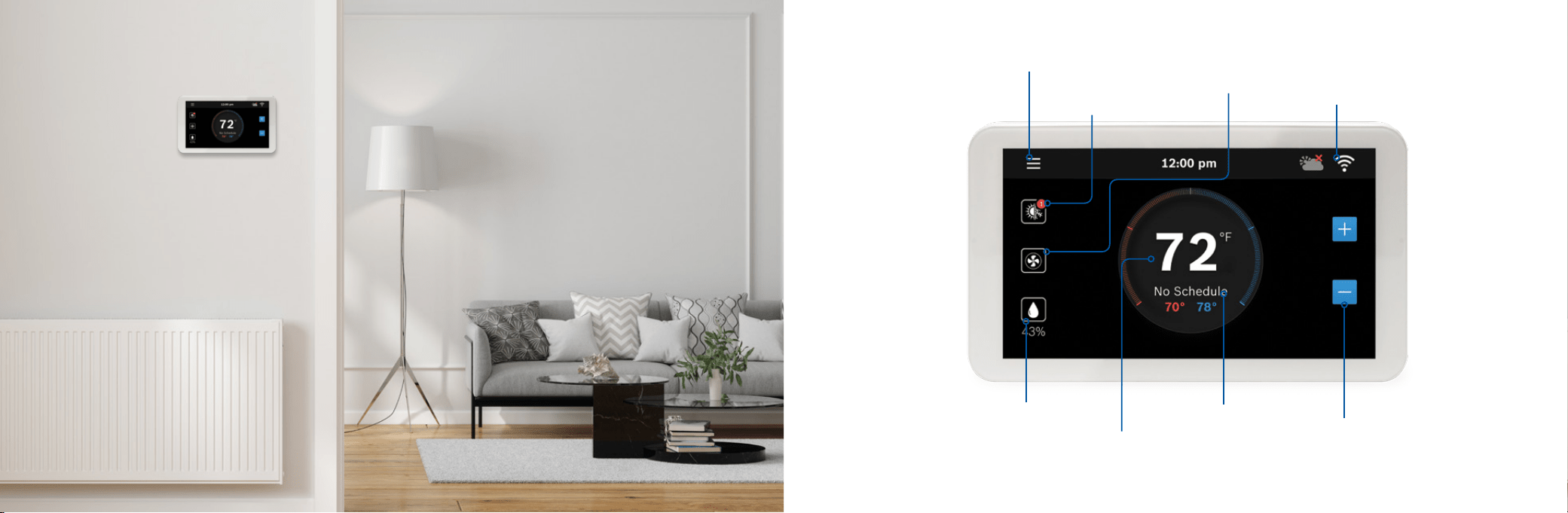
Main Screen
System
Mode
Main Menu Fan
Status
Wifi / Cloud Access
Indicator
Current
Room Humidity
Current Room
Temperature
Current
Schedule
Adjust Temperature
Set-Points
32 33
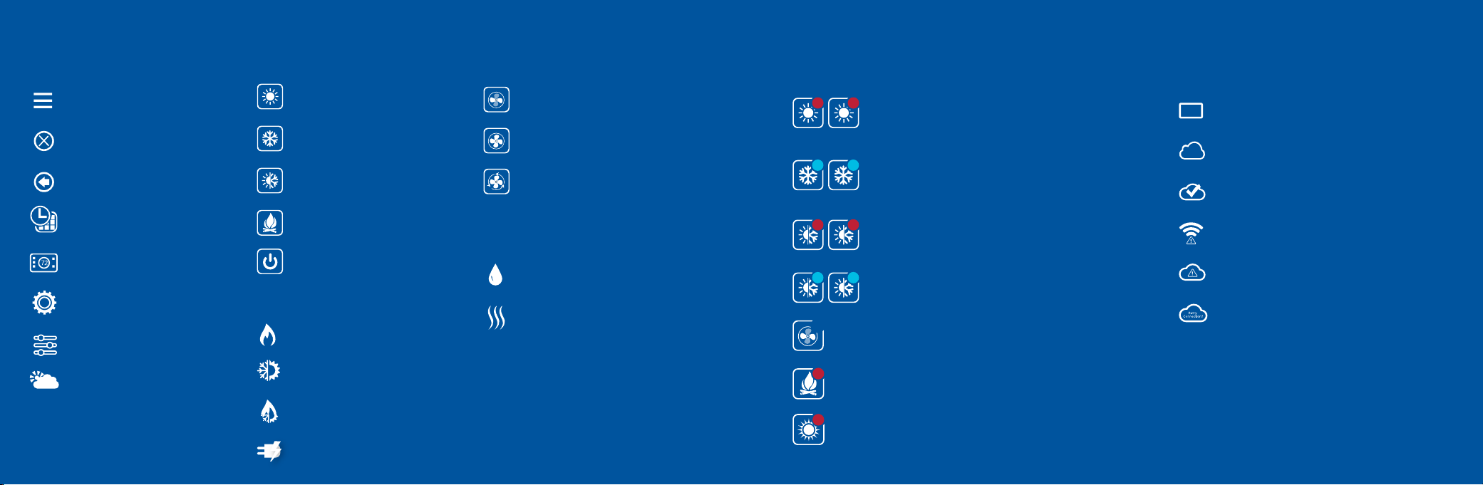
Thermostat and App Icons
Menu
Exit / Save Settings
Back
Schedule
Device Settings
System Settings
Advanced Setting
Weather
Fossil Fuel
Heat Pump
Dual Fuel
Electric
Basic Icons
Heating Types
Fan Modes
Accessory
System Modes
Heat Mode
Cool Mode
Auto Mode
Emergency Heat Mode
Off
Auto
On
Circulation
Humidifier
Dehumidifier
32
Unit Operation
1 2
1
2
1 2
1 2
Heat Mode
Heating on (1st stage) & (2nd stage)
Cool Mode
Cooling on (1st stage) & (2nd stage)
Auto Mode
Heating on (1st stage) & (2nd stage)
Auto Mode
Cooling on (1st stage) & (2nd stage)
Fan on/running (Fan Auto Mode)
Emergency heat on (1st stage) & (2nd stage)
Auxiliary heat on - 2nd Aux Stage of a
4-stage heating system
Emergency
Heating
1
33
Schedule on Device
Schedule on Cloud
Wi-Fi Connection Established
Wi-Fi Connection Not Established
Internet is Not Available
Retry Internet Connection
System Connectivity
4
Auxiliary
Heating
34 35
Adjusting Temperature Setpoint(s) Thermostat Overview
Temporary Adjustment
This feature will override the current set point in favor of
the set point you enter until the next programmed time in
the schedule. If you would like to permanently schedule
the new set point, press the lock icon. This will
permanently lock in the adjustment until the X button is
pressed on the main screen.
Schedule Override on the Thermostat
You can override the current scheduled set point(s) by
tapping the plus or minus (+/-) icons on the right side of
the screen.
If you are in Auto mode, manually adjust either the
Heat/Cool set points individually by selecting the appropriate
bubble, then tapping the plus or minus (+/-) icons. If a Heat/Cool
bubble is not selected pressing the (+/-) icons will adjust both
setpoints simultaneously.
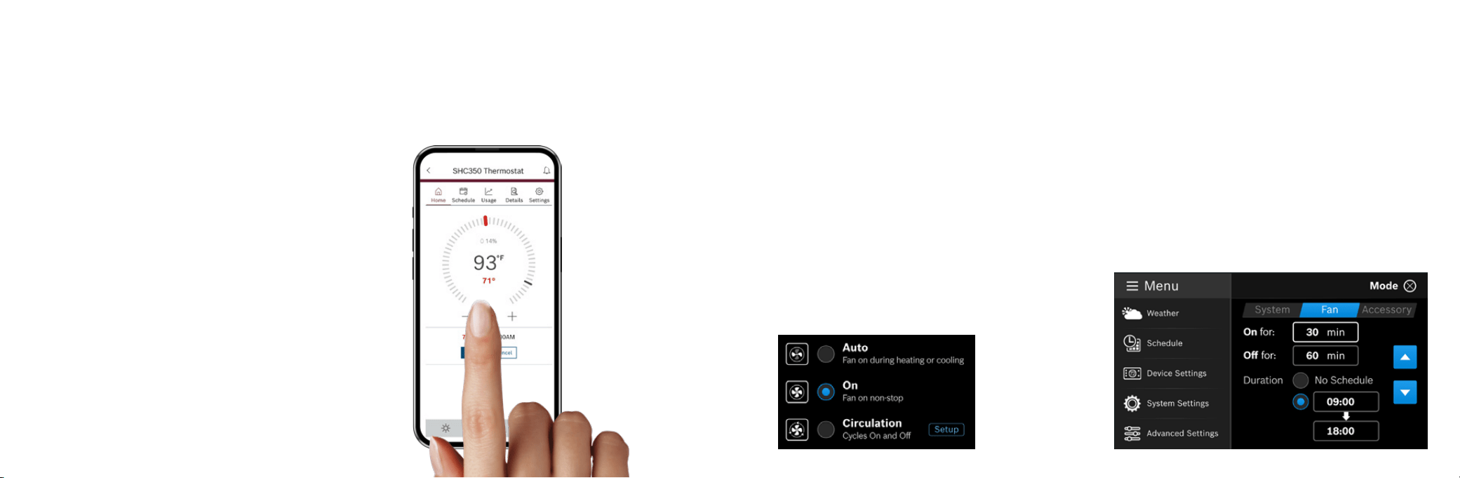
Schedule Override on the App
You can override the current schedule by scrolling the
temperature up and down with your finger.
Unit Operating Mode
Heat: The thermostat cycles your heating appliance to maintain your scheduled heating set point.
Cool: The thermostat cycles your cooling appliance to maintain your scheduled cooling set point.
Auto: The thermostat cycles your heating/cooling appliance to maintain your scheduled heating/cooling set points.
Off: The thermostat turns off all heating/cooling functions. You can still manually operate the fan in this mode.
Emergency Heat (available only with Heat Pumps): The thermostat turns off all compressor stage(s) and activates the
back-up electric heat source(s).
Fan Operation
Auto: Fan will follow heating and cooling operations.
On: Fan runs non-stop.
Circulation: Fan cycles on and off regularly in addition to
heating and cooling operations. By selecting this option, you also
need to define the operation length of time and schedule for the
circulation.
36 37
Thermostat Overview
Humidifier & Dehumidifier Operating Mode
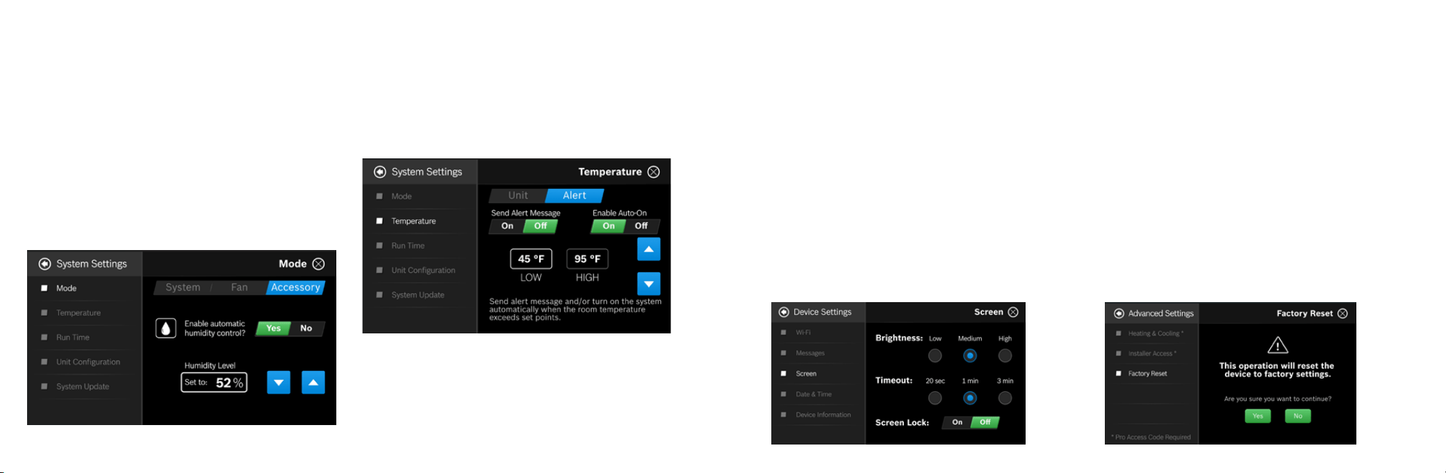
You can enable automatic humidity control if the correct humidifier or
dehumidifier accessory was correctly wired and configured during the
thermostat’s initial setup. Based on the setup, the thermostat turns on
the humidifier during heating operation and the dehumidifier will be
turned on during cooling operation. You can also configure the
thermostat to operate similar to a humidistat, which runs the humidifier
or dehumidifier, regardless of an active heating/cooling call.
Note: You may only operate in either humidifier OR dehumidifier
mode and may not operate in both modes at the same time.
Run Time
The thermostat keeps track of your run time for the Heating, Cooling,
Air Filter and Water Pad. You can also set a reminder for Air Filter and
Water Pad according to the number of calendar days. When it reaches
its predefined run time, the thermostat displays a notification and sends
a message to the registered smart device(s).
Temperature, Alerts, and Auto-On
Alert: Send an alert message or turn on the system automatically
when the room temperature is out of the range between set-points.
Note: Alerts are an additional source of protection for your heating/
cooling appliance.
Device Information
Device information will contain all the relevant Account and System
information.
Account: Change or remove the account associated with
the thermostat.
System: Displays the current hardware and software information.
This screen can also be used to update the firmware.
Factory Reset
To reset the thermostat to its default factory settings, select Advanced
Settings from the main menu, and choose Factory Reset.
Note: All settings will be lost and you will need to repeat the Initial
Setup process as outlined in the Installation Guide.
Weather Forecast
The weather forecast is based on the location of the installed
thermostat. The first time you connect your thermostat to the app,
your location was assigned to the thermostat.
Note: You must grant “location access” for the app to enable this
feature.
Screen Options
There are 3 levels of screen brightness and 3 options
for Screen Timeout.
You can also utilize this menu to Lock the screen.
A 4-digit passcode will be required to lock the screen.
Note: It is important that you remember your screen
lock passcode as you will not be able to unlock the
screen without this code.
Additional Information
38 3939
Download
The GoTemp
Home App
Control all of your
thermostat’s settings.
Adjust your schedule on-
the-go or set your home
to vacation mode to save
energy while you’re away.
The app allows you to remotely control all of your
thermostat’s settings. It also allows you to adjust
your schedule on-the-go or set it to vacation
mode to save energy while you’re away. You can
also connect an unlimited number of thermostats
and manage up to 4 schedules per thermostat.
This is a perfect solution to help you achieve
maximum comfort with minimum effort!
GoTemp Home App
Three Ways to Download
The GoTemp Home App
XIn the App Store or Google Play,
search “GoTemp Home App”
and then download the app.
40 41
App Home Tab
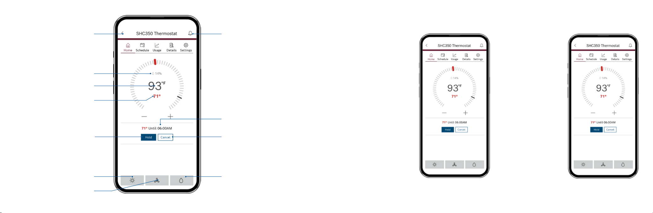
Actual Room Temperature
Heating Setpoint
Accessory
Notifications
Current Schedule Period
System Mode
Fan
Back
Actual Room Relative Humidity
Cancel Schedule Override
Hold
No Schedule
tap the current temperature set
point and use your finger to
drag it left or right to change it.
You can also use the “+” and “-”
buttons to adjust the set point
after tapping it. Stop on the
value you want for your new
setpoint and wait a few seconds
for the setpoint to update. You
will see the update reflected on
the app and on the thermostat.
Note: When the thermostat is
in Auto mode, you must first
select either heat or cool,
depending on which setpoint
you would like to modify, and
then follow the steps above to
change the setpoint.
Adjusting Temperature Setpoint(s) on the App
Schedule
Follow the same process as
above to change the setpoint,
but be aware that you are only
changing the setpoint
temporarily, until the next
scheduled period listed on the
app. If you would like to change
the setpoints for the schedule
periods, please see the section
Schedule further on in this
Manual.
Note: Click Hold to override
the temperature setpoint
permanently. You can cancel
the temporary and permanent
overrides at any time by
clicking Cancel.
42 43
Schedule Overview
Schedule
X
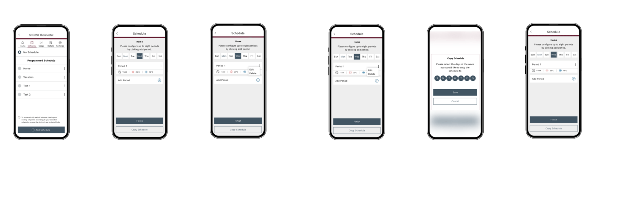
To add a new Schedule, use theAdd Schedule”
button at the bottom, name your schedule and
click OK.
X To modify an existing Schedule, click on the 3
dotted menu button on the schedule you want
to modify and select “Edit” or “Delete”.
Add a New Period
To add a new Period to a given day, click
the Add Period button in the middle of
the screen. Then individually select and
set the Starting time, Heat setpoint and
Cool setpoint.
Edit an Existing Period
To modify an existing Period, click on the 3
dotted menu button on the period you want
to modify and select “Edit”, Then click on the
Starting time, Heat setpoint or Cool setpoint
value you would like to edit and use the scroll
wheel to update the value.
Schedule Overview
Delete an Existing Period
To delete an existing period, click
on the 3 dotted menu button on
the schedule you want to delete
and select “Delete”.
Copy a Schedule
To copy a schedule to other days of the
week, click on the “Copy Schedule” button.
Then lettered days at the bottom of the
screen until all days you would like to copy in
the existing schedule have turned green and
click Copy Schedule.
Save Schedule
Use the Finish button to save
all changes.
44 45
Home
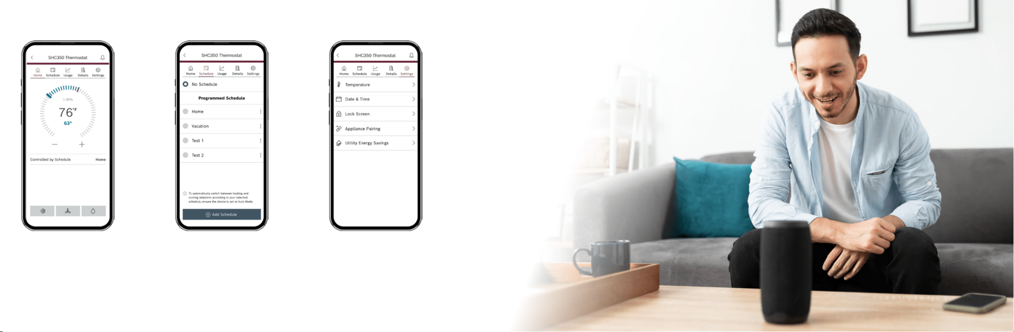
View room temperature and adjust set point.
Use the buttons at the bottom of the thermostat
Home App tab screen to remotely adjust the
System Mode, Fan Mode and Accessory Mode.
App Dashboard Overview
Schedule
Select schedule or follow on screen
instructions to edit default schedule or
add new schedules.
Settings
Use the Settings tab to adjust temperature
settings, date & time, location, screen lock, and
view device information.
“Alexa, Set My
Thermostat to
72 degrees”

46 47
Additional Features
Control Your SHC350 with Amazon Alexa
A Smart Home link is available for integrating your SHC350 with Alexa’s voice controls. Using
the GoTemp Home Skill from the Skills section of the Amazon Alexa App.
Device Name
The Device Name is the name assigned to your device in the GoTemp
Home app. You can check the device name by opening the GoTemp
Home app and reading the name displayed on the main menu of
selectable devices.
You Can Control the SHC350 by Saying:
▶ Alexa, turn (Device Name) on.
▶ Alexa, turn (Device Name) off.
▶ Alexa, Increase (Device Name) by __ degrees.
▶ Alexa, Decrease (Device Name) by __ degrees.
▶ Alexa, Set (Device Name) to __ degrees.
▶ Alexa, what is the (Device Name) set to?
▶ Alexa, what is the temperature of the (Device Name)?
You must have a registered GoTemp Home
account to set up and use your thermostat
with Amazon Alexa.
Connecting Your SHC350 to Amazon Alexa
1. Download the GoTemp Home app, create a SingleKey ID account, and add your SHC350 Thermostat to the app.
2. Download the Amazon Alexa app and set up your Alexa-enabled device.
3. In the Amazon Alexa app, click on the Menu button in the top left corner.
4. Click on the Skills section and search for “GoTemp Home” in the search bar at the top of the page.
5. After you find and click on the GoTemp Home Skill, click on the blue Enable button.
6. The setup process redirects you to the SingleKey ID sign in page where you will need to enter your SingleKey ID username and password.
7. After you have received confirmation that your two accounts have been successfully linked, click Done in the top left hand corner.
8. Next click Discover Devices in the Amazon Alexa app or say “Alexa, discover new devices.” Device Discovery could take up to 45 seconds.
9. When device discovery is complete, you should see a list of connected devices in the Smart Home menu of your Amazon Alexa app.
The setup process is now complete and you can start to control your SHC350 with your Alexa-enabled device.
Try out some of the commands and enjoy!
For further support, contact your installing contractor.

48 49
Additional Features
Control Your SHC350 with Google Assistant
Once installed and connected to the app, a Smart Home link is available for integrating your SHC350 with Google
Assistant’s voice controls. After setting up your thermostat as a new device in the Google Home app:
Device Name
The Device Name is the name assigned to your device in the
GoTemp Home app. You can check the device name by opening
the GoTemp Home app and reading the name displayed on the
main menu of selectable devices.
You Can Control the SHC350 by Saying:
▶ Hey Google, turn (Device Name) on.
▶ Hey Google, turn (Device Name) off.
▶ Hey Google, Increase (Device Name) by _ _ degrees.
▶ Hey Google, Decrease (Device Name) by _ _ degrees.
▶ Hey Google, Set (Device Name) to _ _ degrees.
▶ Hey Google, what is the (Device Name) set to?
You must have a registered GoTemp Home
account to set up and use your thermostat
with Google Assistant.
Connecting Your SHC350 to Google Assistant
1. Download the GoTemp Home app, create a SingleKey ID account, and add your SHC350 Thermostat to the app.
You must have a registered GoTemp Home account to set up and use your thermostat with Google Assistant.
2. Download the Google Home app and set up your Google-enabled device.
3. In the Google Home app, click on the add button in the middle of the screen.
4. Click on Setup up device and select the link option under Works with Google. This is the last option on the page.
5. Search for GoTemp Home and click add new GoTemp Home.
6. The setup process redirects you to the SingleKey ID sign in page where you will need to enter your SingleKey ID account
username and password.
7. Next choose the device(s) you want to link to your Google Home from the available list and click Next.
8. Choose a home for your new thermostat and click Next.
9. Choose a location for your thermostat and click Next
Note: If you have multiple devices, you can continue setting them up one by one until all your devices are setup. You can click the X on the top left
hand corner to return to the home screen of the Google Home app at any time.
The set up process should now be complete and you can start to control your SHC350 Thermostat with your Google-enabled device. Try out some of
the commands and enjoy!
For further support, contact your installing contractor.

50 51
This Limited Warranty applies in the United States (including Puerto Rico) and Canada ONLY.
BHC Residential & Light Commercial LLC or other affiliate identified as the selling entity in the underlying
contractor in the relevant terms and conditions of sale is referred to herein as the “Manufacturer”.
PRODUCT REGISTRATION
For your benefit and protection, register your product with the Manufacturer promptly (no later than 90 days) after installation. This allows us to contact
you, should it become necessary. The Limited Warranty does not require registration. Failure to complete registration does not diminish your
Limited Warranty rights in any way. You can register your product (within 90 days of the installation) online at www.upgproductregistration.com, by
emailing Manufacturer at cg-upgconsumerrelations@bosch-hcgroup.com, or by calling 1-877-874-7378. When registering, provide your name, address,
phone number, Product Model Number, Unit Serial Number, the name of the Participating Dealer (if known), and the Installation Date (if known).
Product Model Number:
Unit Serial Number:
Installation Date:
Participating Dealer:
LIMITED WARRANTY
Manufacturer warrants, to the original* purchaser and consumer (the “Buyer”), the products set forth in the table below (each a “Product”) against failure
due to defects in workmanship or material under normal use when correctly installed and maintained pursuant to Manufacturer’s Installation Manual and
User’s Information Manual (“Manufacturer’s Documentation”) and all local, state, and national codes. Upon proper presentation of a request for warranty
service or repair (as described below), Manufacturer will repair or replace, at its option, a defective Compressor or other Parts (“Parts” defined as parts
of the Product that are not the Compressor or consumable parts or components) without charge, subject to the conditions and exclusions below and
according to the terms set forth in this Limited Warranty. Manufacturer reserves the right, at its sole discretion, to provide an equivalent replacement
Product instead of repairing the Compressor or other Parts. Alternatively, Manufacturer may at its option, offer a replacement price allowance to be
Warranty
applied toward the purchase of a new Product offered by Manufacturer. The exact allowance amount will be determined at the sole discretion of
Manufacturer, based upon, among other things, availability, age of existing Product, and current market conditions. Manufacturer will not be
responsible for costs for shipping, ductwork, wiring, piping, or installation. If a replacement Product, Compressor, or Parts are provided by
Manufacturer under this Limited Warranty, the Warranty Period (as defined below) for the replacement Product, Compressor, or other Parts is limited
to the remainder of the original Warranty Period. With respect to third party parts included in the Products, Manufacturer will pass through the
terms of any warranty provided by the applicable third-party manufacturer or supplier to the extent permitted as the sole warranty for any such
third-party products parts. This Limited Warranty extends only to the Buyer and is non-transferable.*
LIMITED WARRANTY PERIOD
The “Limited Warranty Period” begins on the date the Product is originally installed and ends as set forth in Table 1. If you are unaware of the
Warranty Period, contact Consumer Relations at 1-877-874-7378 or www.upgproductregistration.com. If a Product, Compressor or Part is repaired or
replaced by Manufacturer under this Limited Warranty, the Limited Warranty Period for the repaired or replaced Product, Compressor, or Part is
limited to and shall not extend beyond the remainder of the original Limited Warranty Period.
TABLE 1: LIMITED WARRANTY PERIOD IN YEARS
Models Description Parts
S1-TSHC350 Smart Home Control 350 Thermostat 5 years
Note: *In some states or provinces, the limited warranty is available at no charge to a subsequent owner/homeowner if the product has been used
solely for the original residential application. To determine whether your limited warranty is transferable to a subsequent homeowner (subject to a
transfer fee) please contact Manufacturer at 1-877-874-7378.
Warranty

52 53
MAINTENANCE:
As proper maintenance is a condition to your warranty coverage, Manufacturer strongly recommends coordinating or conducting regular periodic
preventive maintenance on the Product. The person most familiar with the equipment in your HVAC system is the Installing or other Participating
Dealer, who can best ensure that your maintenance program meets the Limited Warranty conditions, maximize the equipment efficiency, and service
your unit within the mandated guidelines with regard to unlawful discharge of refrigerants into the atmosphere.
EXTENDED COVERAGE/ADDITIONAL PROTECTION:
For additional protection, special extended warranty packages, called Residential Home Comfort Plans, are available from a Participating Dealer
(defined as authorized and licensed third-party dealers or contractors that install or are authorized to install the Product(s)). The Residential Home
Comfort Plans provide you with extended years of warranty coverage as well as service protection, including labor charges not covered under the
standard Limited Warranty. Residential Home Comfort Plans must be purchased within one (1) year from the date the original Product is installed or
one (1) year of closing for new home construction. Any extended warranty coverage or service protection granted by a Residential Home Comfort Plan
shall be governed by the terms and conditions of the Residential Home Comfort Plan.
WARRANTY CONDITIONS AND EXCLUSIONS:
This Limited Warranty is void and unenforceable if:
▶ The Product serial number is removed, tampered with, defaced, or altered.
▶ The Product is not sold by an authorized and licensed third-party Participating Dealer that also installs the Product.
To verify an authorized Participating Dealer, call 1-877-874-7378.
▶ The Product is not installed in accordance with Manufacturer’s instructions or local, state, and national codes, is modified without Manufacturer’s
authorization, is subjected to improper or faulty storage, shipment, installation, operation, service, or maintenance (or lack of maintenance),
unauthorized alteration, tampering, abuse, mishandling, misapplication, or is otherwise removed from its place of original installation.
Warranty
▶ The Product is damaged by use or incorporation of improper parts, components or accessories not authorized or approved by Manufacturer
or otherwise not compatible or suitable for use in or with the Product. For a list of parts that are known to be compatible, please reference
the equipment renewal parts list, contact a Participating Dealer for assistance, or call 1-877-874-7378.
▶ The Product is damaged due to accident, acts of God or disaster, or other causes beyond the control of Manufacturer, including but not
limited to excessive voltage, mechanical shock, inadequacy or interruption of electrical service or fuel supply, water damage, inadequacy or
interruption air or water supply, freezing of condenser water or condensate, excessive condensation, corrosive water, atmosphere or
environment, intrusion of water or foreign matter, or fouling or restriction of the water circuit by foreign material or like causes.
This Limited Warranty does not cover and expressly excludes the following:
▶ Shipping, labor, refrigerant or material charges.
▶ Labor or other costs incurred for or in connection with the diagnosing, removing, installing, shipping, servicing, or handling of either
defective parts or replacement parts.
▶ Damages resulting from transportation, installation, or servicing, or from any other issue rendering the Limited Warranty void or enforceable
as set forth above.
▶ Repair or replacement of non-covered parts.
▶ Normal or routine maintenance or service as outlined in the installation and servicing instructions or owner’s manual, including but not
limited to cleaning or replacement of filters, nozzles, or orifices, replacement of fuses, either internal or external to the product, or
replacement of other consumables or components that must be replaced as part of a regular maintenance program such as oil, refrigerant,
filters, belts, and/or batteries.
▶ Electricity or fuel costs, or increases in fuel or electric costs, for any reason including additional or unusual use of supplemental electric heat.

54 55
DISCLAIMERS AND LIMITATIONS OF LIABILITY
This Limited Warranty is exclusive and made in lieu of all other warranties, remedies, rights, or conditions, whether written, oral, or
implied other than by operation of law. Except as stated in this Limited Warranty, Manufacturer makes no representations or warranties of
any kind. To the maximum extent permitted by applicable law, all warranties implied by operation of law, including the implied warranty of
merchantability and fitness for a particular purpose, are specifically limited in duration to the duration of this Limited Warranty.
The limited remedies described herein are the sole and exclusive remedies available, and Manufacturer’s sole responsibility, under this
Limited Warranty. In no event, whether as a result of breach of warranty or contract, tort (including negligence), strict liability, or
otherwise, shall Manufacturer be liable to you for special, incidental, indirect, or consequential damages or expenses, including but not
limited to loss of use of the Product or associated equipment, lost business, revenues or profits, or the cost of substitute products or
equipment, even if Manufacturer was previously advised of or aware of the possibility of such damages and whether or not such damages
are foreseeable. In no event shall Manufacturer’s aggregate liability under this Limited Warranty or otherwise with respect to the specific
Product purchased hereunder, regardless of the cause or fault, exceed the amounts paid by you for the Product (exclusive of installation)
giving rise to such liability, however arising, irrespective of the cause of action or theory of liability.
This Limited Warranty gives you specific legal rights, and you may also have other rights which vary from state to state. Some states do
not allow limitations on how long an implied warranty lasts and/or do not allow the exclusion of limitation of incidental or consequential
damages, so the above exclusions and limitations may not apply to you. In addition, the above limitation on consequential damages shall
not apply to injuries to persons in the case of consumer goods.
The above limitations shall inure to the benefit of Manufacturer’s affiliates, authorized sellers and distributors, and agents. Manufacturer does not
assume, nor does it authorize any other person or entity to assume for Manufacturer, any other liability for the sale of this Product.
DISCLAIMERS AND LIMITATIONS OF LIABILITY
To request warranty service or repair under this Limited Warranty, notify your Participating Dealer, preferably in writing, as soon as
possible after discovery of the problem, and provide the following information:
▶ Your name, address and contact information
▶ The Product Model Number and Unit Serial Number
▶ The location of the Product
▶ Proof of purchase and the date the Product was originally delivered and installed
▶ The Participating Dealer
▶ A reasonably detailed description of the problem (proof of proper maintenance of the Product may be required)
You may find the Participating Dealer’s name on the first page of this Limited Warranty, or on the Product, if they
provided it, and you can locate Participating Dealers in your area online at:
▶ YORK
®
- http://www.york.com/Residential-Equipment/Find-a-Dealer
▶ Coleman
®
- https://www.colemanac.com/residential-equipment/find-a-dealer
▶ Luxaire
®
- https://www.luxaire.com/residential-equipment/find-a-dealer
▶ Champion
®
- https://www.championhomecomfort.com/residential-equipment/find-a-dealer
▶ Fraser Johnston
®
- https://www.fraser-johnston.com/residential-equipment/find-a-dealer
or contact Manufacturer at 1-877-874-7378 for additional assistance.
If a Participating Dealer response is not received within a reasonable amount of time, notify Manufacturer at: Consumer Relations,
5005 York Dr., Norman, OK 73069, by phone at 1-877-874-7378, or by email at: cgupgconsumerrelations@bosch-hcgroup.com.
All warranty service or repair will be performed during regular business hours, Monday through Friday 9:00 AM - 5:00 PM.
Service requests sent to Manufacturer without prior Dealer contact will be referred to a Participating Dealer.
56 57
FCC WARNING
This device complies with part 15 of the FCC Rules. Operation is subject to the following two conditions:
(1)this device may not cause harmful interference,
(2) this device must accept any interference received, including interference that may cause undesired operation.
Any changes or modifications not expressly approved by the party responsible for compliance could void the user's authority to operate the
equipment.
NOTE: This equipment has been tested and found to comply with the limits for a Class B
digital device, pursuant to Part 15 of the FCC Rules. These limits are designed to provide
reasonable protection against harmful interference in a residential installation. This equipment generates, uses and can radiate radio frequency
energy and, if not installed and used in
accordance with the instructions, may cause harmful interference to radio communications.
However, there is no guarantee that interference will not occur in a particular installation.
If this equipment does cause harmful interference to radio or television reception,
which can be determined by turning the equipment off and on, the user is encouraged to try to correct the interference by one or more of the
following measures:
-- Reorient or relocate the receiving antenna.
-- Increase the separation between the equipment and receiver. -- Connect the equipment into an outlet on a circuit different
from that to which the receiver is connected.
-- Consult the dealer or an experienced radio/TV technician for help.
To maintain compliance with FCC’s RF Exposure guidelines, This equipment should be installed and operated with minimum distance
between 20cm the radiator your body: Use only the supplied antenna.
IC CAUTION
This device contains licence-exempt transmitter(s)/receiver(s) that comply with Innovation, Science and Economic Development Canada
’s licence-exempt RSS(s). Operation is subject to the following two conditions:
(
1) This device may not cause interference; and
(2) This device must accept any interference, including interference that may cause undesired
T
operation of the device.
o maintain compliance with RF exposure guidelines, this equipment should be installed and operated with a minimum distance
of
20cm between the radiator and your body.
Cet appareil contient des émetteurs/récepteurs exemptés de licence qui sont conformes aux RSS exemptés de licence d' innovation,
sciences et développement économique Canada. Le fonctionnement est soumis aux deux conditions suivantes:
(1) ce dispositif ne peut pas causer d’interférence.
(2) ce dispositif doit accepter toute interférence, y compris l' interférence qui peut causer un fonctionnement indésirable du dispositif.
Pour maintenir la conformité aux directives d'exposition aux radiofréquences, cet équipement doit être installé et utilisé avec une distance
minimale de 20 cm entre le radiateur et votre corps.

Source 1 HVAC Service Parts
7250 N Hayes Dr, Park City, KS 67147
For support regarding the SHC350 and GoTemp Home App, contact:
- 1-800-283-3787
Copyright © 2026 BHC Residential & Light Commercial LLC.
All rights reserved. Subject to change without notice.
Version Française