1
DOC. NO. 593801601
EDITION 1 2007 02
- CUOCIPASTA ELETTRICO A CONTROLLO ELETTRONICO Pag. 5
INSTALLAZIONE, USO E MANUTENZIONE
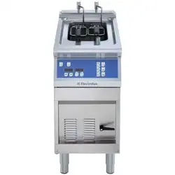
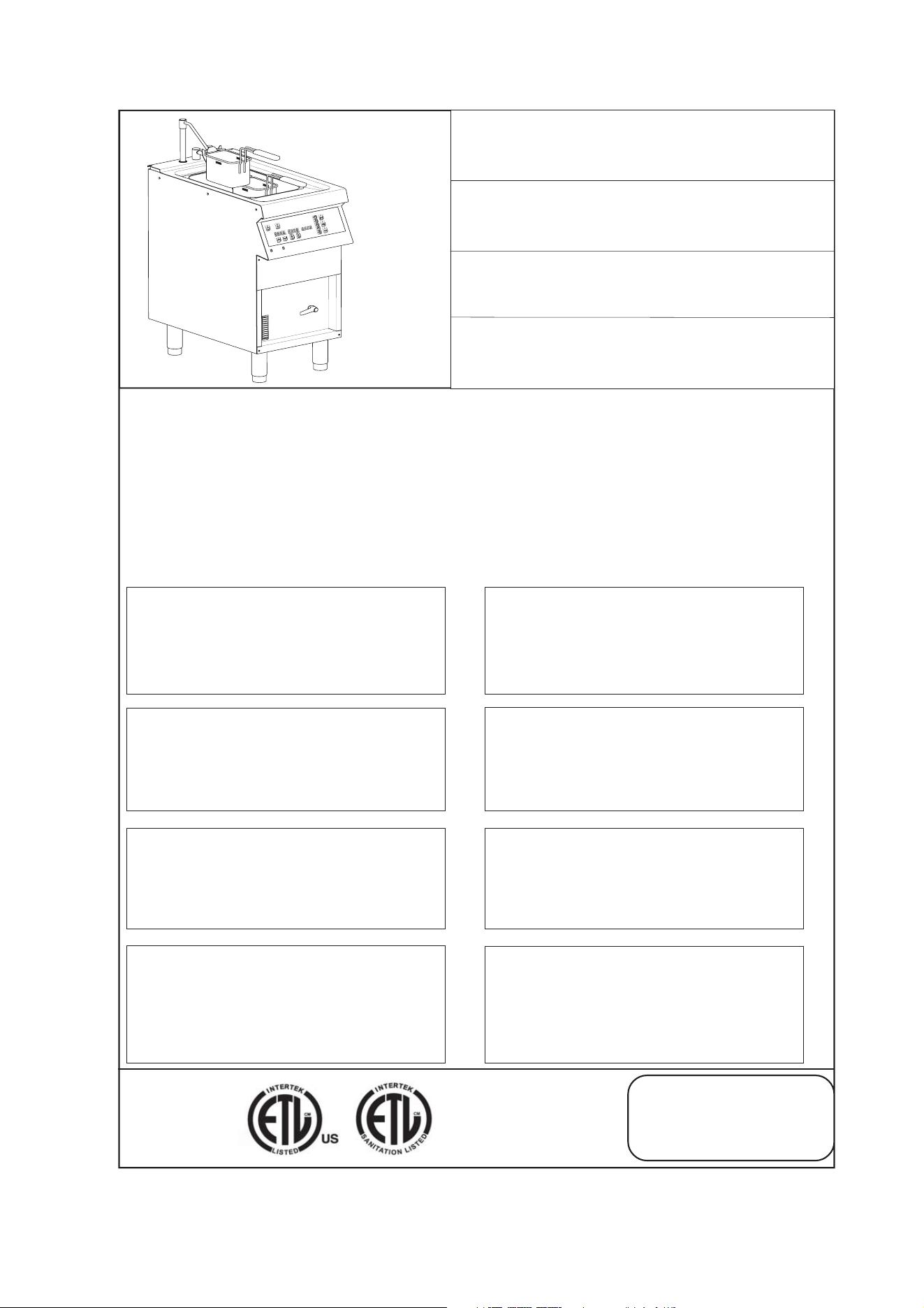
- ELECTRIC PASTA COOKER
WITH ELECTRONIC CONTROL Page 13
INSTALLATION, USE AND MAINTENANCE
- CUISEUR DE PÂTES ÉLECTRIQUE À COMMANDE ÉLECTRONIQUE Page 21
INSTALLATION, UTILISATION ET MAINTENANCE
- CUECEPASTAS ELÉCTRICO CON CONTROL ELECTRÓNICO Pág. 29
INSTALACIÓN, USO Y MANTENIMIENTO
Series N700
Mod. 178141
Read each section of this manual before
installing and operating
Lire toutes les parties de ce mode d’emploi
avant d’installer ou mettre en fonction l’ap-
pareil.
Leer todas las partes de este manual antes
de llevar a cabo la instalación o de poner
en marcha el aparato.
Leggere tutte le parti di questo manuale
prima di installare o mettere in funzione
l'apparecchiatura.
FOR YOUR SAFETY
Do not store or use gasoline or other flammable
vapors or liquids in the vicinity of this or any
other appliance.
WARNING: Improper installation, adjustment,
alteration, service or maintenance can cause
property damage, injury or death. Read the
installation, operating and maintenance
instructions thoroughly before installing or
servicing this equipment
PER LA VOSTRA SICUREZZA
Non immagazzinare o usare benzina o altri mate-
riali infiammabili o liquidi nelle vicinanze di que-
sta o qualsiasi altra apparecchiatura.
AVVERTENZA: Installazione impropria, adattamen-
ti, modifiche o manutenzione possono causare danni
alla proprieta` o morte. Leggere attentamente le istru-
zioni per l'installazione, il funzionamento e la manu-
tenzione prima di installare questa apparecchatura
AVERTISSEMENT: L’installation, l’adaptation, la
modification et l’entretien inadéquats peuvent causer
des dommages aux structures ou aux personnes et la
mort. Lire attentivement les instructions d’installation,
de fonctionnement et d’entretien avant d’installer cet
appareil
ADVERTENCIA: Una instalación indacuada, lo mismo
que modificaciones y operaciones de mantenimiento
incorrectas pueden causar daños a la estructura y a las
personas y provocar la muerte. Antes de instalar el
aparato leer con mucha atención las instrucciones de
la instalación, del funcionamiento y del mantenimiento
POUR VOTRE SECURITE
Il ne faut pas emmagasiner ou utiliser l’essence
ou d’autres matériaux inflammables ou liquides à
côté de cet appareil ou d’autres appareils.
PARA SALVAGUARDAR VUESTRA
SEGURIDAD
No almacenar o utilizar gasolina u otros materia-
les inflamables o líquidos cerca de este u otros
aparatos.
2
IA.
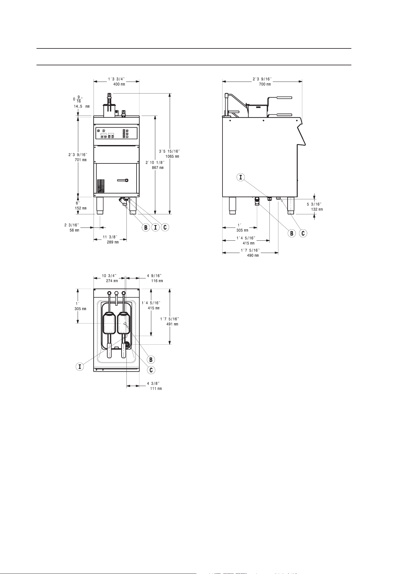
SCHEMA DI INSTALLAZIONE - INSTALLATION DIAGRAM - SCHÉMA D’INSTALLATION - ESQUEMA DE INSTALACIÓN
GB
B - Water connection inlet
I - Power supply cable inlet
C - Water drain connection
FR
B - Entrée eau
I - Entrée câble électrique
C - Ecoulement eau
IT
B - Attacco alimentazione acqua
I - Entrata cavo elettrico
C - Attacco scarico acqua vasca
ES
B - Conexión de agua
I - Ingreso cable eléctrico
C - Conexión de descarga agua
3
1B
1F
1E
1A
1C
180
1D
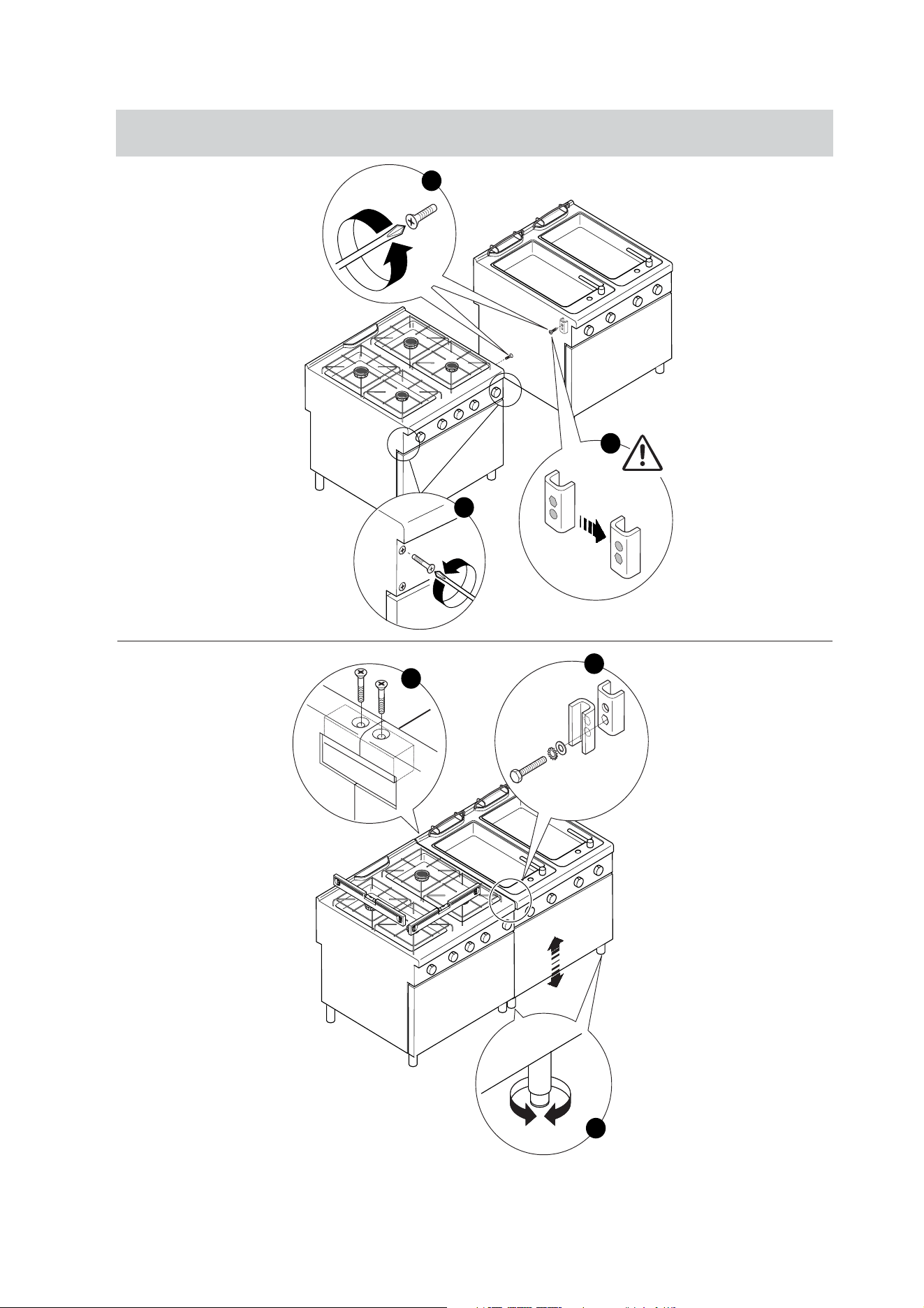
UNIONE APPARECCHIATURE - COMBINING APPLIANCES - UNION D’APPAREILS - UNIÓN DE VARIOS EQUIPOS
1.
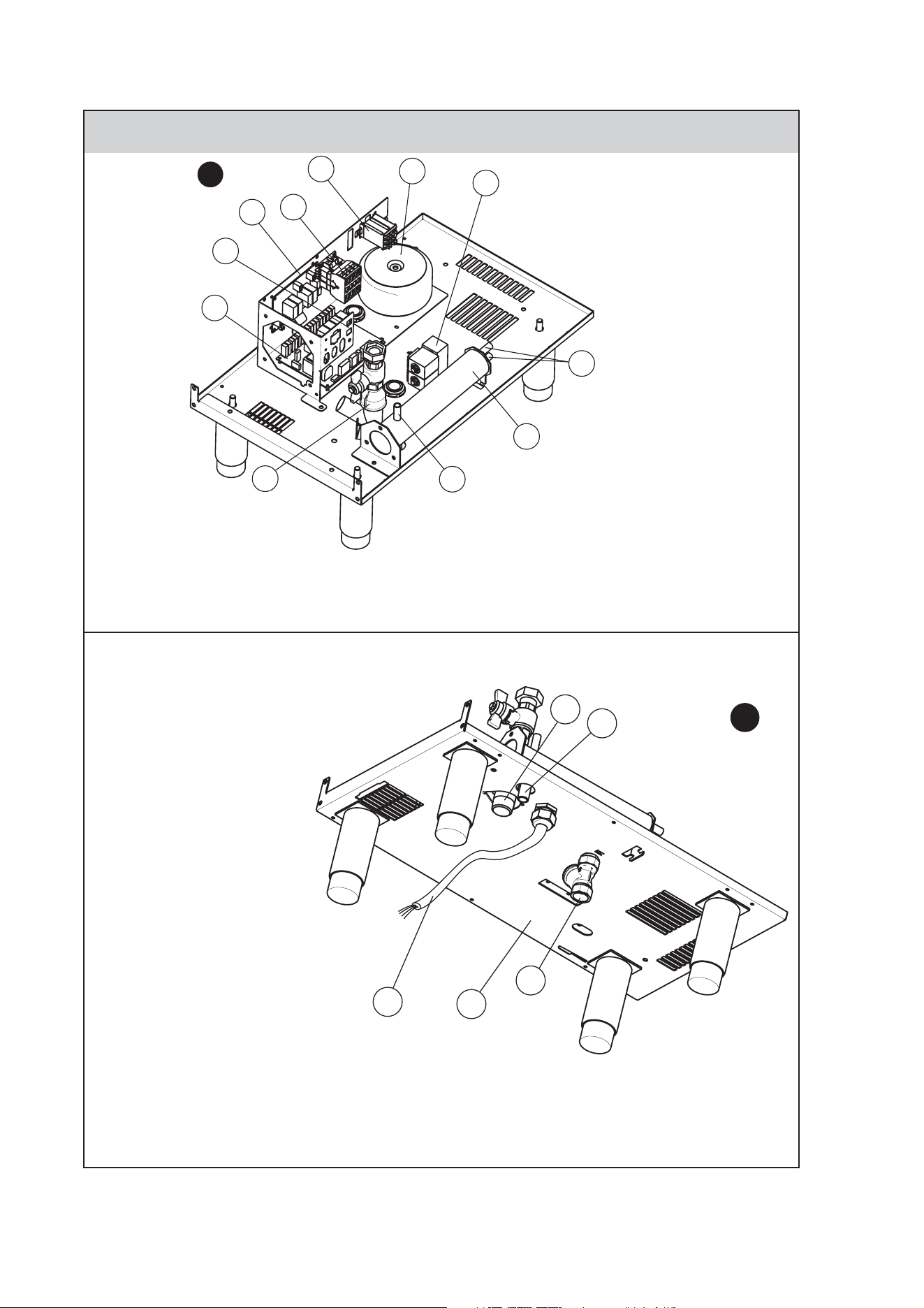
4
PROSPETTO COLLEGAMENTI ELETTRICI - ELECTRICAL CONNECTIONS PROSPECT - TABLEAU DES
BRANCHEMENTS ÉLECTRIQUES - VISTA DE LAS CONEXIONES ELÉCTRICAS
2.
4A
1
2
3
4
8
5
6
7
5
9
10
10
11
11
4B
12
12
13
13
14
14
15
15
16
16
IT
12 - Clip cavo
13 - Filtro acqua
14 - Scarico boiler
15 - Scarico vasca
16 - Cavo alimentazione tipo SJO 10 AWG (4 cavi)
GB
12 - Cable clip
13 - Water strainer
14 - Boiler drain
15 - Tank drain
16 - Supply cord type SJO 10 AWG (4 wires)
FR
12 - Clip câble
13 - Filtre eau
14 - Conduit de vidange surchauffeur
15 - Conduit de vidange cuve
16 - Câble d'alimentation de type SJO 10 AWG (4 câbles)
ES
12 - Clip del cable
13 - Filtro de agua
14 - Desagüe de la caldera
15 - Desagüe de la cuba
16 - Cable de alimentación tipo SJO 10 AWG (4 cables)
FR
1 - Relais surchauffeur
2 - Relais carte
3 - Carte mère
4 - Contacteur puissance
5 - Surchauffeur
6 - Raccord surchauffeur
7 - Électrovanne eau
8 - Autotransformateur
9 - Sortie surchauffeur
10 - Vanne de vidange
11 - Fusibles
IT
1 - Relais boiler
2 - Relais scheda
3 - Scheda madre
4 - Contattore potenza
5 - Boiler
6 - Attacco boiler
7 - Elettrovalvola acqua
8 - Autotrasformatore
9 - Uscita boiler
10 - Valvola scarico
11 - Fusibili
GB
1 - Boyler Relay
2 - Relays board
3 - Mother board
4 - Power contactor
5 - Boiler
6 - Boiler inlet
7 - Water solenoid valve
8 - Autotransformer
9 - Boiler outlet
10 - Drain valve
11 - Fuses
ES
1 - Relé de la caldera
2 - Relé de la tarjeta
3 - Tarjeta madre
4 - Contactor potencia
5 - Caldera
6 - Empalme de la caldera
7 - Electroválvula de agua
8 - Autotransformador
9 - Salida de la caldera
10 - Válvula de desagüe
11 - Fusibles

13
INDEX
I. INSTALLATION DIAGRAM / COMBINING APPLIANCES / FIGURES ..................................................................................... 2
II. DATAPLATE and TECHNICAL DATA ......................................................................................................................................... 14
III. GENERAL INSTRUCTIONS........................................................................................................................................................ 15
IV. THE ENVIRONMENT .................................................................................................................................................................. 16
V. INSTALLATION............................................................................................................................................................................ 16
1. REFERENCE STANDARDS ........................................................................................................................................................ 16
2. UNPACKING ................................................................................................................................................................................ 16
3. POSITIONING .............................................................................................................................................................................. 17
4. FUME EXHAUST AND VENTILATION ........................................................................................................................................ 17
5. CONNECTIONS ........................................................................................................................................................................... 17
6. FUSE REPLACEMENT ................................................................................................................................................................ 17
VI. INSTRUCTIONS FOR THE USER ................................................................................................................................................ 18
1. PASTA COOKER USE ................................................................................................................................................................. 18
VII. CLEANING ................................................................................................................................................................................... 19
1. EXTERNAL PARTS...................................................................................................................................................................... 19
2. OTHER SURFACES ..................................................................................................................................................................... 19
3. SCALE .................................................................................................................................................................................... 19
4. IDLE PERIODS ............................................................................................................................................................................ 20
5. INTERNAL PARTS ....................................................................................................................................................................... 20
VIII. MAINTENANCE .......................................................................................................................................................................... 20
1. MAINTENANCE ........................................................................................................................................................................... 20
14
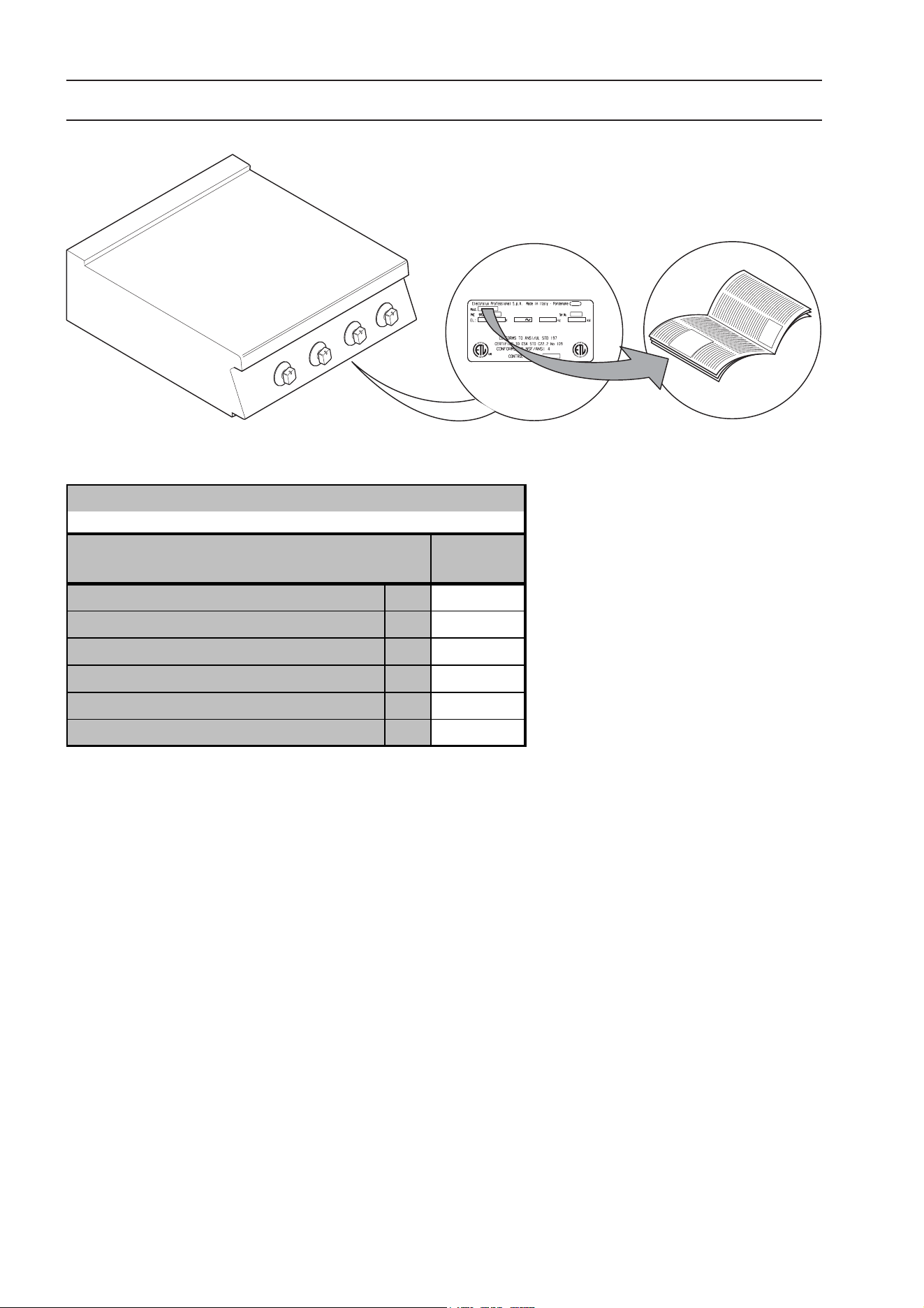
II. DATAPLATE and TECHNICAL DATA
Tank capacity (filling level) L
18
Pow er supply voltage V
208
Phases No.
3
Freque ncy Hz
60
Max. Power kW
8,6
Power cable section AWG
10
TABLE A - Electric appliance technical data
TECHNICAL DATA
178141
ECP/E1EL HU
400m m
MODELS
15
III. GENERAL INSTRUCTIONS
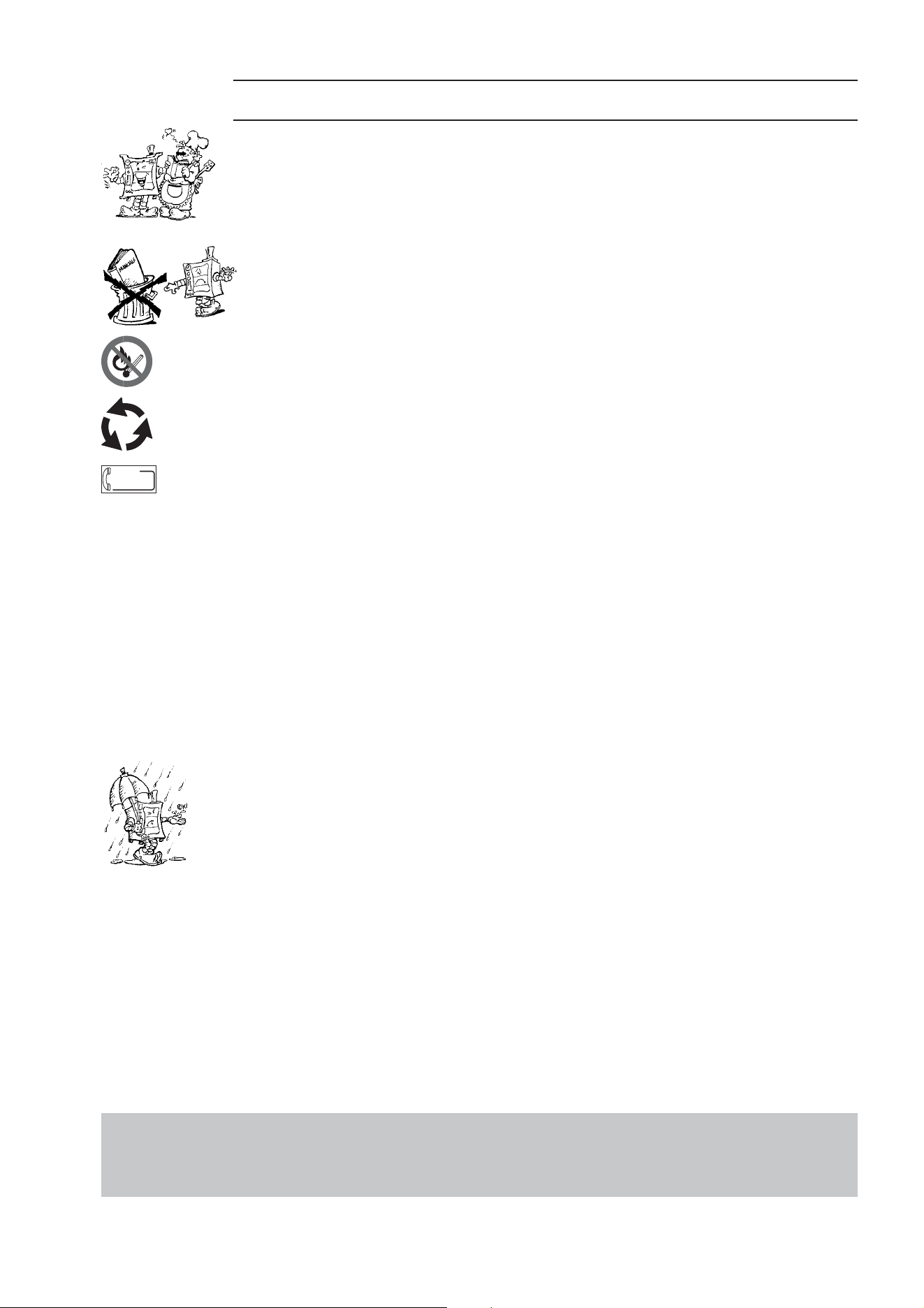
• Carefully read the instruction handbook before using the appliance.
• After installation keep the instruction handbook for future consultation.
• FIRE HAZARD - Keep the area around the appliance clear and free from combustible materials.
Do not keep flammable materials in the vicinity of the appliance.
• Only install the appliance in a well-ventilated place. Inadequate ventilation causes asphyxia.
Do not obstruct the ventilation system of the place where the appliance is installed. Do not
obstruct the vents or ducts of this or other appliances.
• Place emergency telephone numbers in a visible position.
• Installation and maintenance must only be carried out by qualified personnel authorised by the manufacturer.
For assistance, contact an authorised technical centre. Demand original spare parts.
• This equipment is designed for cooking food. It is intended for industrial use. Any other use is to be considered
improper.
• The appliance must be used by trained personnel. Do not leave the appliance unattended when operating.
• Turn the appliance off in case of fault or poor operation.
• Do not use products (even if diluted) containing chlorine (sodium hypochlorite, hydrochloric or muriatic acid,
etc.) to clean the appliance or the floor under it. Do not use metal tools to clean steel parts (wire brushes or
Scotch Brite type scouring pads).
• Do not allow oil or grease to come into contact with plastic parts.
• Do not allow dirt, fat, food or other residuals to form deposits on the appliance.
• Do not clean the appliance with direct jets of water.
• The symbol L given on the product indicates that it should not be considered domestic waste, but must be
correctly disposed of in order to prevent any negative consequences for the environment and the health of
persons.
For further information regarding the recycling of this product, contact the product agent or local dealer, the
after-sales service or the local body responsible for waste disposal.
• Warnings:
• Do not store or use gasoline or other flammable vapours, liquids or items in the vicinity of this or any other
appliance.
• Do not spray aerosols in the vicinity of this appliance while it is in operation.
• The appliance is not suitable for a marine environment.
.
Failure to observe the above can compromise the safety of the appliance. Failure
to observe the above invalidates the warranty.
sos
16
V. INSTALLATION
• Carefully read the installation and maintenance
procedures given in this instruction manual before
installing the appliance.
• Installation and maintenance must only be
carried out by qualified personnel authorised by
the manufacturer.
• Failure to observe the correct appliance
installation, conversion and modification procedures can
cause damage to the appliance, danger to persons and
invalidate the Manufacturer’s warranty.
1. REFERENCE STANDARDS
• The electrical connection must be carried out in conformity
with the current local safety regulations.
• This equipment is to be installed to comply with the
applicable federal, state or local codes.
These installation procedures must be followed by qualified
personnel or warranty will be void.
The National Fire Protection Association, Inc states in its
NFPA latest edition that local codes are the "authority
having jurisdiction" when it comes to installation
requirements for equipment. Therefore, installations
should comply with all local codes.
• The equipment is to be installed with adequate backflow
protection to comply with applicable federal, state, and
local codes.
2. UNPACKING
WARNING!
Immediately check for any damage caused during
transport.
• The forwarder is responsible for the goods during transport
and delivery.
• Inspect the packing before and after unloading.
• Make a complaint to the forwarder in case of visible or
hidden damage, reporting any damage or shortages on
the dispatch note on delivery.
• The driver must sign the dispatch note: the forwarder can
reject the claim if the dispatch note is not signed (the
forwarder can provide the necessary form).
• Unpack, taking care not to damage the
equipment. Wear protective gloves.
• Carefully remove the protective film from metal
surfaces and clean any traces of glue with a suitable solvent.
• For hidden damage or shortages becoming apparent only
after unpacking, request the forwarder for inspection of
the goods within and not later than 15 days of delivery.
• Keep all the documentation contained in the packing.
IV. THE ENVIRONMENT
1. PACKING
Packing materials are environment friendly and can
be stored without risk, or burned in a special waste
incineration plant.
Recyclable plastic components are marked with:
Polyethylene: outer wrapping, instruction booklet
bag.
Polypropylene: roof packing panels, straps.
Polystyrene foam: corner protectors.
2. USE
Our appliances offer high performance and efficiency. To re-
duce consumption of electricity, water or gas, do not use the
appliance empty or in conditions that compromise optimal
efficiency; the appliance is used in a well-ventilated place to
avoid the creation of dangerous mixtures of unburnt gases
in the room. Whenever possible, pre-heat only before use.
3. CLEANING
In order to reduce the emission of pollutants into the
environment, clean the appliance (externally and when
necessary internally) with products that are more than 90%
biodegradable (for further information, see chap. V
“CLEANING”).
4. DISPOSAL
Do not dispose in the environment. Our
appliances are manufactured using more
than 90% (in weight) recyclable metals
(stainless steel, iron, aluminium, galvanised
steel, copper, etc.).
Make the appliance unusable by removing
the power cable and any compartment or cavity closing
mechanisms (when present) in order to avoid the risk of
someone becoming closed inside.
PE
PP
PS
17
3. POSITIONING
• Handle the equipment with care in order to avoid damage or
danger to persons. Use a pallet for handling and positioning.
• The installation diagram given in this instruction manual gives
the appliance dimensions and the position of connections
(gas, electricity, water). Check that they are available and
ready for making all the necessary connections.
• The appliance can be installed separately or combined
with other appliances of the same range.
• The appliances are not designed for built-in installation. Leave
at least 10 cm between the appliance and side or rear walls.
• Suitably insulate surfaces that are at distances less than
those recommended.
• Maintain an adequate distance between the appliance
and any combustible walls. Do not store or use flammable
materials and liquids near the appliance.
• Leave an adequate space between the appliance and any
side walls in order to enable subsequent servicing or
maintenance operations.
• Check and if necessary level the appliance after
positioning. Incorrect levelling can cause appliance
malfunctioning.
3.1. COMBINING APPLIANCES
• (Fig.1A) Undo the 4 fixing screws and remove the control
panels of the appliances.
• (Fig.1B) Remove the fixing screw nearest the control
panel, from each side to be joined.
• (Fig.1D) Bring the appliances together and level them by
turning the feet until the tops match.
• (Fig.1C) Turn one of the two plates inside the appliances 180º.
• (Fig.1E) From inside the control panel of the same
appliance, join them at the front side, screwing one TE
M5x40 screw (supplied) on the opposite insert.
3.2. FLOOR FIXING
To avoid accidental tipping of built-in half-module appliances installed
separately, fix them to the floor carefully following the instructions
enclosed with the relevant optional accessory (F206136).
3.3. SEALING GAPS BETWEEN APPLIANCES
Follow the instructions supplied with the optional sealing
paste pack.
4. FUME EXHAUST AND VENTILATION
• Only install the appliance in a well-
ventilated place.
• Do not obstruct the ventilation system
in any way.
• Do not obstruct the vent and discharge
holes of this appliance or others present in
the room.
WARNING! Inadequate ventilation
causes appliance malfunction and can
cause asphyxia and danger for persons.
5. CONNECTIONS
• Any installation work or maintenance to the
supply system (electricity, water) must only be
carried out by the utility company or an authorised
installation technician.
• See the appliance dataplate for the product code.
• See the installation diagram for the type and position of
appliance connections.
5.1. ELECTRIC APPLIANCES
5.1.1. ELECTRICAL CONNECTION (Fig. 4A -Table A).
IMPORTANT! Before connecting, make sure the mains voltage
and frequency match that given on the dataplate; the connection
to the electrical supply must be carried out according to the
standards in force.
• A protecting onnipolar switch must be installed upstream
from the appliance with a suitable capacity and a contact
opening, comply with current regulations.
• This switch must be installed in the building’s main power supply
line and near the appliance.
• It is important to connect the appliance to an efficient
earth outlet. The appliance must be included in an
unipotential system. This connection is carried out with a
setscrew marked
, placed under the appliance.
IMPORTANT! The manufacturer declines any liability if the
safety regulations are not respected.
5.2. WATER CONNECTION
The appliance must be supplied with drinking water at a
pressure of 1.5 - 3 bar.
Important! If the water pressure is higher than that specified,
use a pressure reducer to avoid damaging the appliance.
For correct installation, water inlet pipe “C” (fig.4A) must be
connected to the mains using a mechanical filter and an on/
off valve. Before connecting the filter, allow a certain amount
of water to flow in order to clear the pipe of any waste matter.
5.3. DISCHARGE
Discharge water must be removed by means of a suitable
receptacle resistant to a temperature of at least 100°C. The
steam produced during the discharge phases must not involve
the appliance.
6. FUSE REPLACEMENT
The electrical system protection fuse is located inside the
panel (“11” fig. 4A). To replace the fuses, unscrew the fuse
holder cap and remove it.
18
VI. INSTRUCTIONS FOR THE USER
rice and similar products in water. Any other use is to be
considered improper.
• The appliance must not be used as a fryer.
• Fill the water tank only up to the reference mark.
• Do not use the appliance dry.
• Before use, carefully clean any industrial greases from the
tank and baskets, proceeding as follows:
• Fill the tank with water and normal detergent and bring to
boil for a few minutes.
• Empty the tank by means of the drain valve (“10” fig. 4A)
and carefully rinse it with clean water.
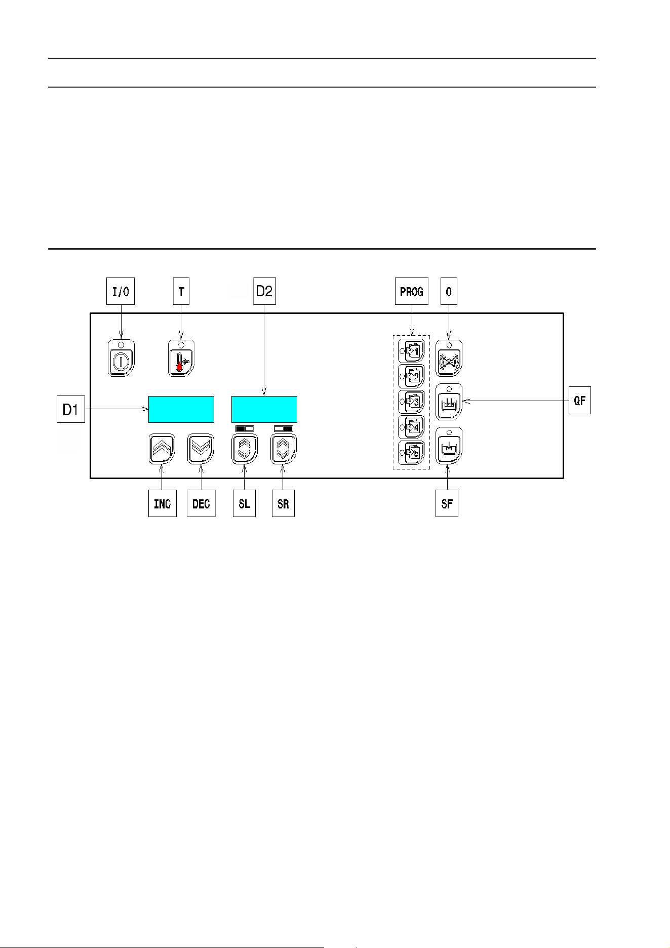
I/O - ON/OFF button
T - Temperature real time visualization button
INC - Temperature increasing setting buttons (standard
mode) / Time increasing setting buttons (programming mode
only)
DEC - Temperature decreasing setting button (standard
mode) / Time increasing setting button (programming mode
only)
SL - Left side basket start/stop button
SR - Right side basket start/stop button
PROG - Resume program buttons
0 - Free button (factory operations)
QF - Quick water filling start/stop button
SF - Slow water filling start/stop button
D1 - Temperature display up to 99°C - Energy level display
over 99°C (standard mode)/Time display (programming
mode only)
D2 - Active program display
SWITCH ON AND TEMPERATURE CONTROL
Press button I/O to switch ON: lamp test and tank water filling
will run automatically; when the tank has been filled the
appliance will start heating, depending on the temperature
set by the operator.
The heating is controlled as follows:
- from 50°C up to 99°C push buttons INC/DEC to increase/
decrease the temperature (each pressing increase/decrease
by 1°C; holding on one of the buttons INC/DEC will make
increasing/decreasing faster);
- over 99°C push buttons INC/DEC to increase/decrease the
energy level (o=50%; oo=75%; ooo=90%; oooo=100%);
- visualize real time temperature in the tank for a couple of
seconds: push button T.
The appliance will automatically set the temperature/energy
level at the value working when switched OFF (factory
deliveries at 50°C).
AUTOMATIC LIFTING PROGRAMS
This appliance is equipped with 2 or 4 (depending on the
model) lifting motors controlled by a user friendly electronic.
It is possible to program different cooking cycles and store
up to 5 different cooking times, easy to resume for a quick
swap from a recipe to another.
1. PASTA COOKER USE
1.1 GENERAL PRECAUTIONS
• The appliance is intended for industrial use and must be
used by trained personnel.
• Do not use the appliance empty or in conditions that com-
promise its optimum efficiency. Also, if possible, pre-heat
the appliance immediately before use.
• This appliance must only be used for its specifically
designed purpose, i.e. for cooking foods such as pasta,

19
SET A TIME (programming mode)
Press and hold one of the buttons PROG (buttons PROG are
called respectively: p1, p2, p3, p4, p5) until the relevant
name is displayed on D2, the relevant time is displayed on
D1 and the pushed button is backlighted.
Push buttons INC/DEC to increase/decrease the time (with
steeps of 5 seconds) from 15 seconds up to 20 minutes of
cooking time.
Swap to another time program just pushing on another of the
buttons PROG and store new time (active button is always
backlighted).
Push and hold the backlighted button PROG until escaping
from the programming mode.
ASSIGN PROGRAMS TO LIFTER
Push one of the buttons PROG to resume one of the pre-set
time; the button will be backlighted. Push the button SL to
assign the time of the backlighted program to the left side
lifter; push the button SR to assign the time of the backlighted
program to the right side lifter.
Push the backlighted button PROG for escaping from the
assignment mode.
START/STOP A COOKING CYCLE
Push one of the buttons SL/SR: the lifter will go down and
count down will start in hidden mode; last 10 seconds of the
program will be displayed on D2.
Stop the cooking cycle at need by pushing on the button of
the relevant lifter.
MANUAL WATER FILLING
Start/Stop quick water filling at need by pushing button QF.
Start/Stop slow water filling at need by pushing button SF.
SWITCH OFF
Push button I/O to switch OFF the appliance.
WATER DRAIN
Always empty the tank for avoiding corrosive deposits.
Always wait the water cools down till 60°C before emptying
the tank.
Empty the tank by operating on the knob “10” (Fig. 4A) of
the draining valve.
AT THE END OF WORK
• Make sure the power is switched off.
• Drain the water from the tank by opening drain valve
“10”, fig. 4A.
• Wash any residuals of food from the tank and baskets.
• Turn off the main switch and the water valve upstream
the appliance.
VII. CLEANING
CAUTION!
Before carrying out any cleaning operation, disconnect the
appliance from the power supply.
1. EXTERNAL PARTS
SATIN-FINISH STEEL SURFACES (daily)
• Clean all steel surfaces: dirt can be easily removed as
soon as it forms.
• Remove grime, fat and other cooking residuals from steel
surfaces when cool using soapy water, with or without detergent,
and a cloth or sponge. Dry the surfaces thoroughly after cleaning.
• In case of encrusted grime, fat or food residuals go over
with a cloth or sponge, wiping with the grain of the satin
finish, and rinsing often: rubbing in a circular motion
combined with the particles of dirt on the cloth/sponge
could ruin the steel’s satin finish.
• Metal objects can ruin or damage the steel: ruined surfaces
become dirty more easily and are more subject to corrosion.
• Restore the satin finish if necessary.
SURFACES BLACKENED BY HEAT (when necessary)
Exposure to high temperatures can cause the formation of dark
marks. These do not constitute damage and can be removed by
following the instructions given in the previous paragraph.
2. OTHER SURFACES
HEATED TANKS/CONTAINERS (daily)
Clean the appliance tanks or containers using boiled water,
adding soda (degreasing) if necessary. Use the accessories
(optional or supplied) specified in the list to eliminate
encrustations or food deposits.
IMPORTANT – With electric appliances, make sure no water
comes into contact with electrical components: water
penetration can cause short circuiting and dissipation, tripping
the appliance’s protection devices.
3. SCALE
STEEL SURFACES (when necessary)
Remove any scale (stains or marks) left by hard water on
steel surfaces using suitable natural (e.g. vinegar) or chemical
(e.g. “STRIPAWAY” produced by ECOLAB) detergents.
DESCALING PROCEDURE
HOT WATER TANKS (at least once a month)
Descale the parts used for water storage and heating by
filling them with a solution of chemical detergent (1/3) and
water (2/3), carrying out the following procedure:
• Connect a rubber hose to the boiler drain, on the bottom of
the unit, ensuring that it is tight;
• Open the drain valve under the bottom, and empty the
boiler;
• With the valve open, introduce the scale remover via the
rubber hose, until the liquid comes out the dispenser spout
on the shelf;
• Close the valve, keeping the hose lifted;
• After letting it drip for a few seconds, allow the scale
remover to work (at least a couple of hours);
• Empty the boiler;
• Close the valve and do a wash cycle with the tank drain
open and fast fill on, for at least 5 minutes.

20
4. IDLE PERIODS
If the equipment is not going to be used for some time, take
the following precautions:
• Close valves or main switches ahead of the appliances.
• Go over all stainless-steel surfaces vigorously with a cloth
moistened with paraffin oil in order to spread a protective
film.
• Periodically air the room.
• Have the appliance checked before using it again.
• To prevent too rapid evaporation of accumulated moisture
with consequent breakage of elements, switch electric
appliances on at minimum heat for at least 45 minutes
before reuse.
5. INTERNAL PARTS
(every 6 months)
IMPORTANT! Operations to be carried out only by
specialised technicians.
• Check the condition of internal components.
• Remove any deposits of grime inside the appliance.
• Check and clean the drain system.
NB ! In particular environmental conditions (e.g. intensive
use of the appliance, salty environment, etc.) the above
cleaning should be more frequent.
VIII. MAINTENANCE
1. MAINTENANCE
Servicing shall only be carried out by authorised
personnel
All the components requiring maintenance are accessible
from the front of the appliance, after removing the control
panel and front panel. Disconnect the power supply before
opening the appliance
1.1. MAINTENENCE SCHEDULE
• It is reccommended the appliance is inspected and
serviced by an authorized person at least every 12
months. For this purpose it is reccommended to draw up
a maintenece contract.

