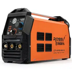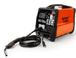
User manual
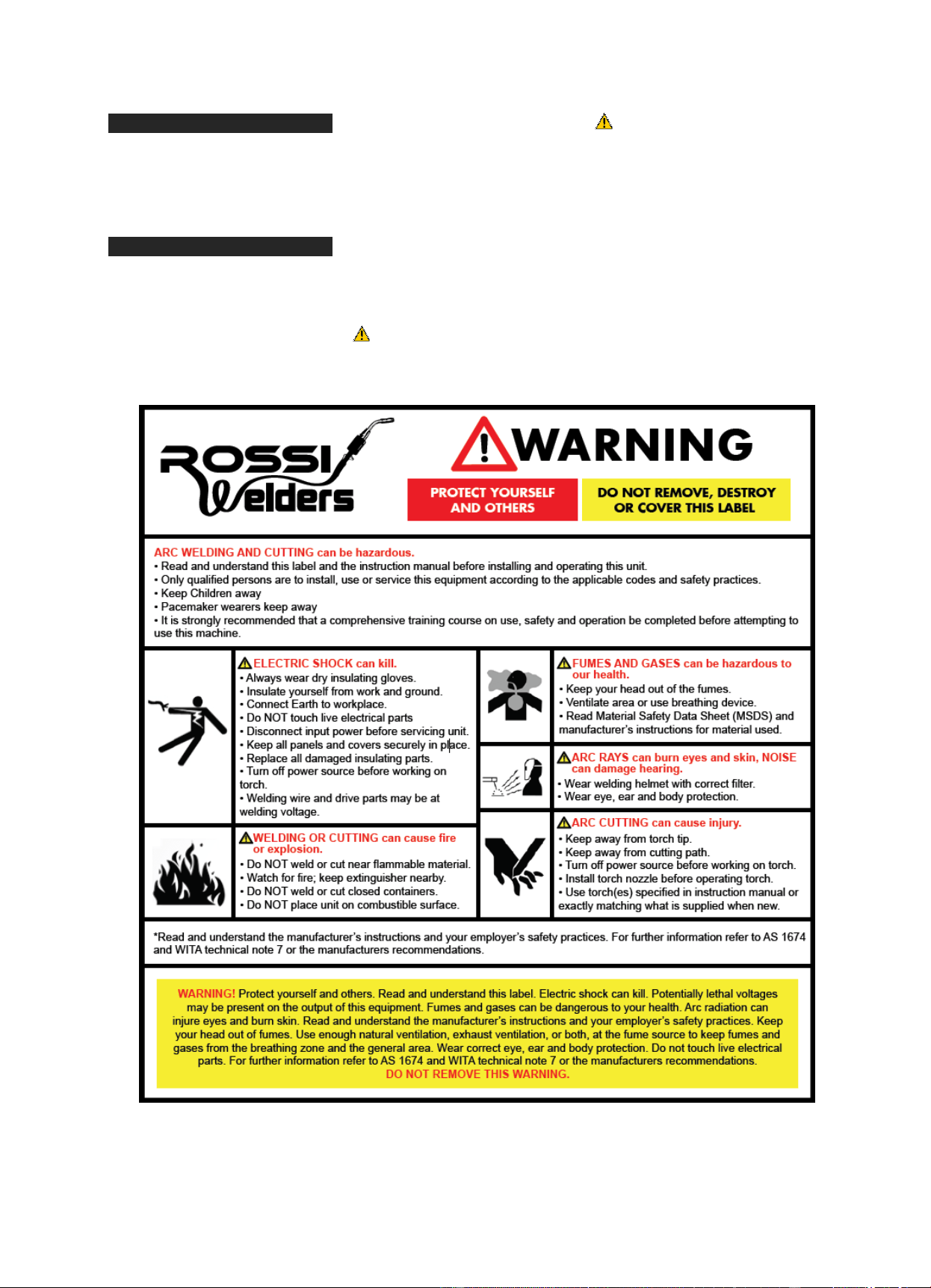
WARNING! Read and understand all
safety warnings and instructions carefully
before using this machine. Failure to
follow the warnings and instructions may
result in electric shock, fire and/or serious
injury. Save this manual for future
reference.
ATTENTION! Products covered by this
manual will vary in appearance, assembly,
inclusions, description and packaging.
NOTE! This manual covers multiple styles
of product as well as options / accessories
that may not be suitable for the machine
you have purchased.
Downloaded from www.ManualsFile.com manuals search engine

Product Manual – Rossi Welders
Index
Index ............................................................................................................................................................ 1
Safety ........................................................................................................................................................... 2
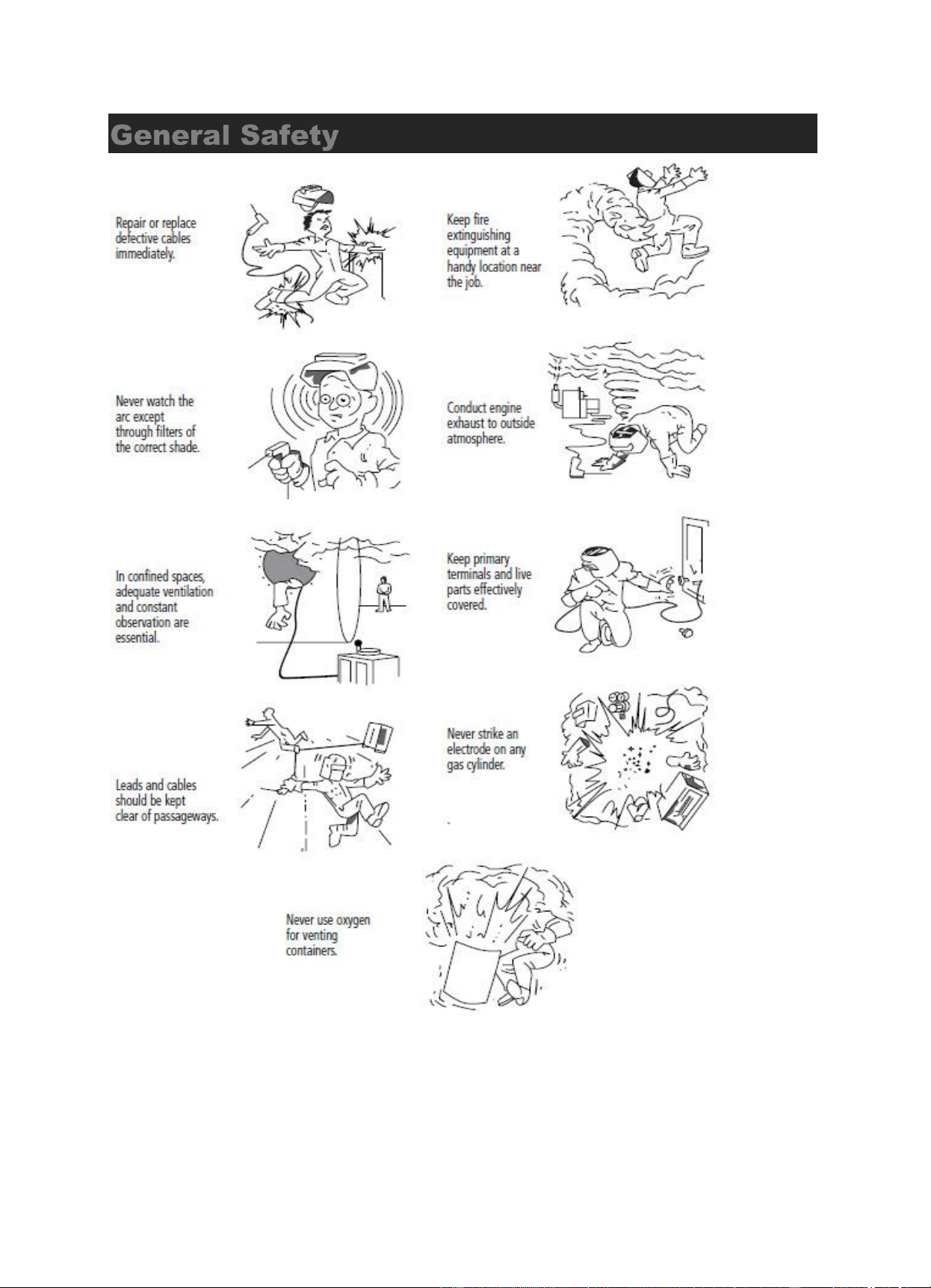
General Safety ........................................................................................................................................... 12
Parts Diagram ............................................................................................................................................ 13
Which welder do I need? ............................................................................................................................ 22
Types of Welding ........................................................................................................................................ 22
ARC / Stick Welding ...................................................................................................................................................................... 22
MIG Welding / Gas Metal Arc Welding (GMAW) ........................................................................................................................... 23
TIG Welding / Gas Tungsten Arc Welding (GTAW) ...................................................................................................................... 23
Pulsed TIG Welding ...................................................................................................................................................................... 24
Plasma Cutting .............................................................................................................................................................................. 25
Getting Started ........................................................................................................................................... 26
TIG welding Basics ....................................................................................................................................................................... 26
ARC Welding Basics ..................................................................................................................................................................... 27
Installing MIG wire ........................................................................................................................................................................ 28
Troubleshooting .......................................................................................................................................... 31
Arc Welding Faults ........................................................................................................................................................................ 33
Travel Speed Faults ...................................................................................................................................................................... 33
Current Setting Faults ................................................................................................................................................................... 34
TIG Welding Faults ....................................................................................................................................................................... 35
MIG Welding Faults ...................................................................................................................................................................... 36
Plasma Cutting Faults ................................................................................................................................................................... 37
Specifications ............................................................................................................................................. 38
Glossary ..................................................................................................................................................... 42
Appendix .................................................................................................................................................... 43
Downloaded from www.ManualsFile.com manuals search engine
Product Manual – Rossi Welders
Safety
Only qualified persons should install, operate, maintain, and repair this unit.
ATTENTION! This manual is provided to assist the owner of the product to understand
the functions it provides and how to prepare the equipment. This manual does not seek
to teach the user how to perform the actual task it is used for. It is strongly
recommended that a comprehensive training course on the machines use, safe
handling and operation be completed before attempting to use this machine.
It is important you read
and understand the
instruction manual
before use and keep the
manual in a safe place for
future reference.
Safety precautions must
be observed to reduce
the risk of personal injury
when operating this
machine.
It is strongly
recommended that a
comprehensive training
course on machine use,
handling and operation
be completed before
attempting to use this
machine.
IMPORTANT! Like all power
equipment this unit must be
handled carefully.
DANGER! Electric Shock can
kill.
DANGER! Exposure to fumes
and gases can damage the
lungs and respiratory system or
cause asphyxiation.
Work area safety
Keep work area clean and well lit.
Cluttered or dark areas invite
accidents. Do not operate equipment in
explosive atmospheres, such as in the
presence of flammable liquids, gases
or dust. Equipment creates sparks
which may ignite. Keep children and
bystanders away while operating
equipment.
Personal safety
Stay alert, watch what you are doing
and use common sense when
operating equipment. Do not use
equipment while you are tired or under
the influence of drugs, alcohol or
medication. A moment of inattention
while operating equipment may result
in serious personal injury. Use personal
protective equipment. Always wear eye
protection. Protective equipment such
as dust mask, non-skid safety shoes,
hard hat, or hearing protection used for
appropriate conditions will reduce
personal injuries. Ensure the
equipment is switched off before
connecting to power source, picking up
or carrying the equipment. Never carry
equipment with your finger on the
switches or trigger. Remove any
adjusting key or wrench before turning
the equipment on. Do not overreach.
Keep proper footing and balance at all
times. This enables better control of the
equipment in unexpected situations.
Dress properly. Do not wear loose
clothing or jewellery. Keep your hair
and clothing away from the work area.
Loose clothes, jewellery or long hair
can be caught in moving parts. If
devices are provided for the connection
of dust and fume extraction and
collection facilities, ensure these are
connected and properly used.
Equipment use and care
Do not force the equipment. Use the
correct equipment for your application.
The correct equipment will do the job
better and safer at the rate for which it
was designed. Do not use the
equipment if it is found to be faulty,
faulty equipment that cannot be
controlled is dangerous and must be
repaired. Disconnect the plug from the
power source before making any
adjustments, changing accessories, or
storing equipment. Such preventive
safety measures reduce the risk of
starting the equipment accidentally.
Store idle equipment out of the reach of
children and do not allow persons
unfamiliar with the equipment or these
instructions to operate the equipment.
Electrical equipment is dangerous in
the hands of untrained users. Maintain
equipment. Check for misalignment or
binding of moving parts, breakage of
parts and any other condition that may
affect the equipment’s operation. If
damaged, have the equipment repaired
before use. Many accidents are
caused by poorly maintained
equipment. Use the equipment,
accessories and tool bits etc. in
accordance with these instructions,
taking into account the working
conditions and the work to be
performed. Use of the equipment for
operations different from those
intended could result in a hazardous
situation. Keep handles dry, clean and
free from oil and grease. Slippery
handles do not allow for safe handling
and control of the tool in unexpected
situations.
Electrical Safety.
Equipment plugs must match the outlet.
Never modify the plug in any way. Do
not use any adapter plugs with earthed
(grounded) equipment. Touching live
electrical parts can cause fatal shocks
or severe burns. The electrode and
work circuit is electrically live whenever
the output is on. The input power circuit
and machine internal circuits are also
live when power is on. In semi-
automatic or automatic wire welding,
the wire, wire reel, drive roll housing,
and all metal parts touching the welding
wire are electrically live. Incorrectly
installed or improperly grounded
equipment is a hazard. Keep your
gloves and other protective clothing,
dry and free of oil and grease. Never
coil or loop welding cables around your
body. Do not touch live electrical parts.
Wear dry, hole-free insulating gloves
and body protection. Insulate yourself
from work and ground using dry
insulating mats or covers big enough to
prevent any physical contact with the
work or ground. Do not use AC output
in damp areas, if movement is
confined, or if there is a danger of
falling. Don’t weld while standing on a
wet surface or while standing in water.
Use AC output ONLY if required for the
welding process. If AC output is
required, use remote output control if
present on unit.
Additional safety precautions are
required when any of the following
electrically hazardous conditions are
present: in damp locations or while
wearing wet clothing; on metal
Downloaded from www.ManualsFile.com manuals search engine

Product Manual – Rossi Welders
110914123000
3
3
Rossi Welders
structures such as floors, gratings, or
scaffolds; when in cramped positions
such as sitting, kneeling, or lying; or
when there is a high risk of unavoidable
or accidental contact with the work
piece or ground. For these conditions,
use the following equipment in order
presented: 1) a semiautomatic DC
constant voltage (wire) welder, 2) a DC
manual (stick) welder, or 3) an AC
welder with reduced open-circuit
voltage. In most situations, use of a
DC, constant voltage wire welder is
recommended. Do not work alone!
Disconnect input power before
installing or servicing this equipment.
Properly install, ground, and operate
this equipment according to its Owner’s
Manual and national, state, and local
codes. Always verify the supply ground
− check and be sure that input power
cord ground wire is properly connected
to ground terminal in disconnect box or
that cord plug is connected to a
properly grounded receptacle outlet.
When making input connections, attach
proper grounding conductor first −
double-check connections. Keep cords
dry, free of oil and grease, and
protected from hot metal and sparks.
Frequently inspect input power cord for
damage or bare wiring − replace cord
immediately if damaged − bare wiring
can kill. Turn off all equipment when
not in use. Do not use worn, damaged,
undersized, or poorly spliced cables.
Do not drape cables over your body. If
earth grounding of the work piece is
required, ground it directly with a
separate cable. Do not touch electrode
if you are in contact with the work,
ground, or another electrode from a
different machine. Do not touch
electrode holders connected to two
welding machines at the same time
since double open-circuit voltage will
be present. Use only well-maintained
equipment. Repair or replace damaged
parts at once. Maintain unit according
to manual. Wear a safety harness if
working above floor level. Keep all
panels and covers securely in place.
Clamp work cable with good metal-to-
metal contact to work piece or
worktable as near the weld as practical.
Insulate work clamp when not
connected to work piece to prevent
contact with any metal object. Do not
connect more than one electrode or
work cable to any single weld output
terminal. SIGNIFICANT DC VOLTAGE
exists in inverter welding power
sources AFTER removal of input
power. Do not abuse the cord. Never
use the cord for carrying, pulling or
unplugging the equipment. Keep cord
away from heat, oil, sharp edges or
moving parts. Damaged or entangled
cords increase the risk of electric
shock. When operating equipment
outdoors, use an extension cord
suitable for outdoor use. Use of a cord
suitable for outdoor use reduces the
risk of electric shock. If operating
equipment in a damp location is
unavoidable, use a residual current
device (RCD) protected supply. Use of
an RCD reduces the risk of electric
shock. NOTE: The term “residual
current device (RCD)” may be replaced
by the term “ground fault circuit
interrupter (GFCI)” or “earth leakage
circuit breaker (ELCB)”.
Hot Parts can burn.
Don’t touch hot parts bare handed.
Allow cooling period before working on
equipment. To handle hot parts, use
proper tools and/or wear heavy,
insulated welding gloves and clothing
to prevent burns.
Fumes and Gases can be
hazardous.
Welding produces fumes and gases.
Breathing these fumes and gases can
be hazardous to your health. Keep your
head out of the fumes. Do not breathe
the fumes. If inside, ventilate the area
and/or use local forced ventilation at
the arc to remove welding fumes and
gases. If ventilation is poor, wear an
approved air-supplied respirator. Read
and understand the Material Safety
Data Sheets (MSDSs) and the
manufacturer’s instructions for metals,
consumables, coatings, cleaners, and
degreasers. Work in a confined space
only if it is well ventilated, or while
wearing an air-supplied respirator.
Always have a trained watch person
nearby. Welding fumes and gases can
displace air and lower the oxygen level
causing injury or death. Be sure the
breathing air is safe. Do not weld in
locations near degreasing, cleaning, or
spraying operations. The heat and rays
of the arc can react with vapours to
form highly toxic and irritating gases.
Do not weld on coated metals, such as
galvanized, lead, or cadmium plated
steel, unless the coating is removed
from the weld area, the area is well
ventilated, and while wearing an air-
supplied respirator. The coatings and
any metals containing these elements
can give off toxic fumes if welded.
ARC Rays can burn eyes and skin.
Arc rays from the welding process
produce intense visible and invisible
(ultraviolet and infrared) rays that can
burn eyes and skin. Sparks fly off from
the weld. Wear an approved welding
helmet fitted with a proper shade of
filter lenses to protect your face and
eyes from arc rays and sparks when
welding or watching. Wear approved
safety glasses with side shields under
your helmet. Use protective screens or
barriers to protect others from flash,
glare and sparks; warn others not to
watch the arc. Wear protective clothing
made from durable, flame-resistant
material (leather, heavy cotton, or wool)
and foot protection.
Welding can cause fire or
explosion.
Welding on closed containers, such as
tanks, drums, or pipes, can cause them
to blow up. Sparks can fly off from the
welding arc. The flying sparks, hot work
piece, and hot equipment can cause
fires and burns. Accidental contact of
electrode to metal objects can cause
sparks, explosion, overheating, or fire.
Check and be sure the area is safe
before doing any welding. Remove all
flammables within 35 ft (10.7 m) of the
welding arc. If this is not possible,
tightly cover them with approved
covers. Do not weld where flying
sparks can strike flammable material.
Protect yourself and others from flying
sparks and hot metal. Be alert that
welding sparks and hot materials from
welding can easily go through small
cracks and openings to adjacent areas.
Watch for fire, and keep a fire
extinguisher nearby. Be aware that
welding on a ceiling, floor, bulkhead, or
partition can cause fire on the hidden
side. Do not weld on containers that
have held combustibles, or on closed
containers such as tanks, drums, or
pipes unless they are properly
prepared according to AS 1674.1 and
AS 1674.2 "Safety in Welding and
Allied Processes". Do not weld where
the atmosphere may contain flammable
dust, gas, or liquid vapours (such as
gasoline). Connect work cable to the
work as close to the welding area as
practical to prevent welding current
from traveling long, possibly unknown
paths and causing electric shock,
sparks, and fire hazards. Do not use
welder to thaw frozen pipes. Remove
stick electrode from holder or cut off
welding wire at contact tip when not in
use. Wear oil-free protective garments
such as leather gloves, heavy shirt,
cuff-less trousers, high shoes, and a
cap. Remove any combustibles, such
as a butane lighter or matches, from
your person before doing any welding.
After completion of work, inspect area
to ensure it is free of sparks, glowing
embers, and flames. Use only correct
fuses or circuit breakers. Do not
oversize or bypass them. Always have
a fire watcher and extinguisher nearby.
Eye Protection
Welding, chipping, wire brushing and
grinding cause sparks and flying metal.
As welds cool, they can throw off slag.
Wear approved safety glasses with
side shields even under your welding
helmet. Flying Metal or Dirt can injure
eyes.
Gas Safety
Build-up of gas can injure or kill. Shut
off compressed gas supply when not in
use. Always ventilate confined spaces
or use approved air-supplied respirator.
Downloaded from www.ManualsFile.com manuals search engine

Product Manual – Rossi Welders
110914123000
4
4
Rossi Welders
Electric and Magnetic Fields
(EMP) can affect Implanted
Medical Devices.
Wearers of Pacemakers and other
Implanted Medical Devices should
keep away. Implanted Medical Device
wearers should consult their doctor and
the device manufacturer before going
near arc welding, spot welding,
gouging, plasma arc cutting, or
induction heating operations.
Ear Protection
Noise from some processes or
equipment can damage hearing. Wear
approved ear protection if noise level is
high.
Cylinders can explode if
damaged.
Compressed gas cylinders contain gas
under high pressure. If damaged, a
cylinder can explode. Since gas
cylinders are normally part of the
welding process, be sure to treat them
carefully. Protect compressed gas
cylinders from excessive heat,
mechanical shocks, physical damage,
slag, open flames, sparks, and arcs.
Install cylinders in an upright position
by securing to a stationary support or
cylinder rack to prevent falling or
tipping. Keep cylinders away from any
welding or other electrical circuits.
Never drape a welding torch over a gas
cylinder. Never allow a welding
electrode to touch any cylinder. Never
weld on a pressurized cylinder −
explosion will result. Use only correct
compressed gas cylinders, regulators,
hoses, and fittings designed for the
specific application; maintain them and
associated parts in good condition.
Turn face away from valve outlet when
opening cylinder valve. Keep protective
cap in place over valve except when
cylinder is in use or connected for use.
Use the right equipment, correct
procedures, and sufficient number of
persons to lift and move cylinders.
Refer to Australian Standard 4332-
1995 “The storage and handling of
gases in cylinders” for more detailed
guidance on the location and
construction of gas cylinder stores,
including ventilation, operational and
personnel safety and fire protection and
other emergency measures.
Fire or Explosion Safety
Do not install or place unit on, over, or
near combustible surfaces. Do not
install unit near flammables. Do not
overload building wiring − be sure
power supply system is properly sized,
rated, and protected to handle this unit.
Falling Equipment
Use lifting eye or handle to lift unit only,
NOT running gear, gas cylinders, or
any other accessories. Use equipment
of adequate capacity to lift and support
unit. If using lift forks to move unit, be
sure forks are long enough to extend
beyond opposite side of unit. Keep
equipment (cables and cords) away
from moving vehicles when working
from an aerial location.
Overuse can cause Overheating
Allow cooling period; follow rated duty
cycle. Reduce current or reduce duty
cycle before starting to weld again.
Do not block or filter airflow to unit.
Flying Sparks can injure.
Wear a face shield to protect eyes and
face. Shape tungsten electrode only on
a grinder with proper guards in a safe
location wearing proper face, hand, and
body protection.
Sparks can cause fires — keep
flammables away.
Moving Parts can injure.
Keep away from moving parts. Keep
away from pinch points such as drive
rolls.
Welding Wire can injure.
Do not press gun trigger until instructed
to do so. Do not point gun toward any
part of the body, other people, or any
metal when threading welding wire.
Battery Explosion can injure.
Do not use welder to charge batteries
or jump start vehicles unless it has a
battery charging feature designed for
this purpose.
Moving Parts can injure.
Keep away from moving parts such as
fans. Keep all doors, panels, covers,
and guards closed and securely in
place. Have only qualified persons
remove doors, panels, covers, or
guards for maintenance and
troubleshooting as necessary. Reinstall
doors, panels, covers, or guards when
maintenance is finished and before
reconnecting input power.
EMF Information
Electric current flowing through any
conductor causes localized electric and
magnetic fields (EMF). Welding current
creates an EMF field around the
welding circuit and welding equipment.
EMF fields may interfere with some
medical implants, e.g. pacemakers.
Protective measures for persons
wearing medical implants have to be
taken. For example, restrict access for
passers−by or conduct individual risk
assessment for welders. All welders
should use the following procedures in
order to minimize exposure to EMF
fields from the welding circuit:
Keep cables close together by
twisting or taping them, or using a
cable cover.
Do not place your body between
welding cables. Arrange cables to
one side and away from the
operator.
Do not coil or drape cables around
your body.
Keep head and trunk as far away
from the equipment in the welding
circuit as possible.
Connect work clamp to work piece
as close to the weld as possible.
Do not work next to, sit or lean on
the welding power source.
Do not weld whilst carrying the
welding power source or wire
feeder.
Implanted Medical Device wearers
should consult their doctor and the
device manufacturer before performing
or going near arc welding, spot
welding, gouging, plasma arc cutting,
or induction heating operations. If
cleared by your doctor, then following
the above procedures is
recommended.
Service
Have your equipment serviced by a
qualified repair person using only
identical replacement parts. This will
ensure that the safety of the equipment
is maintained.
Additional Safety requirements
This appliance is not intended for use
by persons (including children) with
reduced physical, sensory or mental
capabilities, or lack of experience and
knowledge. Never allow children to
access the tool. If any non-consumable
part is damaged, it must be replaced by
the manufacturer, its service agent or
similarly qualified persons in order to
avoid a hazard. Read the instructions
carefully. Be familiar with the controls
and proper use of the equipment. Wear
eye protection. Never allow children to
access the machine. Avoid using the
equipment, while people, especially
children or pets, are nearby. Use the
equipment only in daylight or good
artificial light. Never operate the
equipment with damaged guards or
shields or without guards or shields in
place. Use only the manufacturer’s
recommended replacement parts and
accessories. Disconnect power from
the equipment before carrying out
maintenance or cleaning work. Inspect
and maintain the tool regularly. Have
the equipment repaired only by an
authorized repairer. Always ensure that
the ventilation openings are kept clear
of debris. When not in use, store the
equipment out of the reach of children.
Before using the machine and after any
impact, check for signs of wear or
damage and repair as necessary.
Maintenance
When not in use store the machine out
of the reach of children; After use,
disconnect the equipment & check for
damage; Use only manufacturers
recommended replacement parts and
accessories.
Downloaded from www.ManualsFile.com manuals search engine
Product Manual – Rossi Welders
110914123000
5
5
Rossi Welders
Warnings
Read the instructions carefully. Be
familiar with the controls and proper
use of the equipment. Welding Safety
Welding and cutting are both specialist
processes, and safety should always
be the number one priority.
Arc Radiation
Arc radiation is a result of ULTRA-
VIOLET (UV) and INFRA-RED (IR)
RAYS and exposure can cause:
- Skin Cancer
- Thermal Skin Burns (severe sun
burn)
- ARC FLASH (Welders Flash) or
EYE BURN which can result in
inflammation of the cornea,
cataracts or blindness.
A welding flash can occur by indirectly
viewing the arc even for a relatively
short time, for example:
1. Unconsciously looking out the
corner of the eye
2. Looking away from the arc
(close eyes then turn away).
3. Reflections of the arc from shiny
surfaces in the welding area.
Advised Protection Required
Includes:
An approved welding helmet with
the correct filter and shade
number.
Safety glasses which will help to
refract (bend away) the UV and IR
rays away, reducing the chances
of Arc Flash.
Always wear protective full covering
clothing to shield your body from
potential burns, for example:
Overalls-flame resistant wool or
cotton.
Leather apron or jacket.
Always wear leather gloves.
Skull cap (for overhead welding).
Screen the welding zone when
welding in open spaces.
Downloaded from www.ManualsFile.com manuals search engine
Product Manual – Rossi Welders
110914123000
6
6
Rossi Welders
IMPORTANT! - Machine, Fuel handling or Electrical Safety; If you are not familiar with safe operation / handling of this machine, or are in any
way unsure of any part of this products suitability or correct use for your application you should complete training conducted by a person or organisation
qualified in safe use and training related to this product.
Downloaded from www.ManualsFile.com manuals search engine

Product Manual – Rossi Welders
110914123000
7
7
Rossi Welders
DANGER! Fumes and Gases are caused by the melting, vaporisation and other reactions of the consumables, base metals and
gases (where applicable) involved in the welding arc.
Some common contaminants:
Contaminant
Source
Iron Fume
Vaporisation of iron from base metal and electrode coatings.
Chromium
Stainless steel, electrode coatings, platings.
Nickel
Stainless steel, nickel-clad steel.
Zinc Fume
Vaporisation of zinc alloys, electrode coatings galvanised steel, zinc-primed steel.
Copper Fume
Vaporisation of coatings on electrode wires, sheaths on air carbon arc gouging electrodes, copper alloys.
Vanadium, Manganese, Molybdenum
Welding rods, alloying elements in steels.
Tin
Tin-coated steel, some nonferrous alloys.
Cadmium
Plating
Lead
Fluxes, coatings on electrodes, flux in wires
Carbon Monoxide
Combustion products of gas metal arc welding, air carbon arc gouging, oxyfuel flames; exhaust from car engines.
Ozone
Gas metal arc welding, air carbon arc gouging; titanium and aluminium welding in inert gas atmospheres
Nitrogen Dioxide
Gas metal arc welding; oxy fuel flame processes.
Phosgene
Welding of metal covered with chlorinated hydrocarbon solvents.
DANGER! Exposure to fumes and gases can damage the lungs and respiratory system or cause asphyxiation.
Downloaded from www.ManualsFile.com manuals search engine

Product Manual – Rossi Welders
110914123000
8
8
Rossi Welders
Advised Protection Required Includes:
- Adequate ventilation.
- Keep your head out of and away from the fumes.
- Use a welding fume respirator, or an air supplied respirator (especially in confined space).
- Use a fume extraction unit/or gun.
NOTE! Welding fume fever caused by breathing fumes formed by the welding of
various metals can occur a few hours after exposure and can last several days.
Symptoms Include:
- Nausea
- Fatigue
- Fever
- Dry nose and throat
- Chills
- Metallic taste in mouth
- Weakness
- Joint and muscle pain
Note: If any of these symptoms are observed please seek professional medical
attention.
Heat, Fire & Sparks
WARNING! Heat, Fire & Sparks are caused by welding and related processes,
operators are at continual risk of burns by hot and molten metal, sparks and heat
radiated from the arc.
WARNING! Welding sparks can travel long distances and have been known to reach up to 15
metres away from the source of welding on the ground and even further when working in elevated
positions.
DANGER! Sparks can reach combustible materials and start fires, as well as burning unprotected
skin.
DANGER! Burns can result from handling hot just welded work (the most common of welding
burns) and molten weld metal (spatter) falling or spitting onto exposed skin.
Advised Protection Required Includes:
- Always wear protective clothing.
- Keep safety glasses on your head where they belong.
- Always mark just welded work with the word “HOT”.
- Know where the nearest fire extinguisher or fire hose is and how to use them.
- Remove combustible materials away from the welding area. (at least 15 metres or 50 feet
away).
- If in an elevated position, post a person on the ground as a fire-watcher.
- Never connect the earth lead to electrical circuits of pipes containing gases or flammable
liquids.
Downloaded from www.ManualsFile.com manuals search engine
Product Manual – Rossi Welders
110914123000
9
9
Rossi Welders
Proper Grounding
Grounding of electrical circuits is a safety practice that is documented in various codes and standards.
A typical arc welding setup may consist of several electrical circuits. Applying and maintaining proper
grounding methods within the welding area is important to promote electrical safety in the workplace.
Associated processes such as plasma cutting will also benefit from proper grounding.
Where welding machines that use a plug on the end of a power cord, the grounding conductor
connection is made automatically when the welding machine is plugged into the receptacle. The
grounding pin of the plug makes a connection within the receptacle.
IMPORTANT! You must still earth your work piece / job.
WARNING! The use of adapters that effectively remove the grounding pin
connection at the plug is not recommended.
WARNING! Do not cut off or remove the grounding pin from the plug. All safety
benefit of the grounding conductor is lost without the connection.
Grounding the Work Piece / Job
The welding circuit consists of all conductive material through which the welding current is intended to
flow. Welding current flows through the welding machine terminals, welding cables, work piece / job
connection, gun, torch, electrode holder and work piece / job itself; the welding circuit is not
connected to ground within the welding machine, but is isolated from ground. How do we ground the
welding circuit?
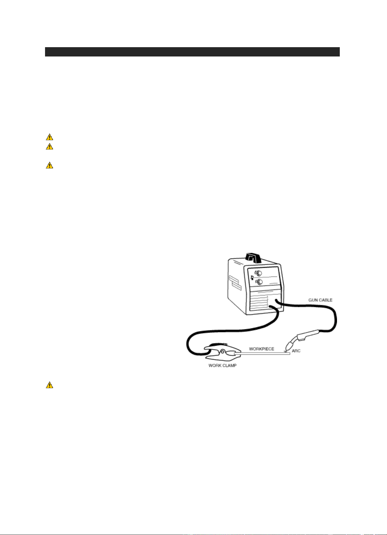
The work piece / job or the metal table that the work piece / job rests upon must be grounded. We
must connect the work piece / job or work
table to a suitable ground, such as a metal
building frame. The ground connection should
be independent or separate from the welding
circuit connection.
Grounding the work piece / job has similar
benefit to grounding the welding machine
enclosure. When the work piece is grounded,
it is at the same potential as other grounded
objects in the area. In the event of insulation
failure in the arc welding machine or other
equipment, the voltage between the work
piece and ground will be limited.
WARNING! Welding Circuit Shock Hazards.
Utilising proper grounding in the welding environment is a good practice, but it does not remove all
possibility of electrical shock. The welding circuit is energised by welding voltage. A person will
receive a shock if they become the electrical path across the welding circuit. Precautions must be
taken to insulate the welder from the welding circuit. Use dry insulating gloves and other insulating
means. Also maintain insulation on weld cables, electrode holders, guns and torches to provide
protection.
Downloaded from www.ManualsFile.com manuals search engine

Product Manual – Rossi Welders
110914123000
10
10
Rossi Welders
Shielding Gas Safety
This article is intended to give users some basic information about the recommended safety
procedures concerning the use of mig/tig welding shielding gases. It does not cover the use of other
gases such as Oxygen or Acetylene as those need much more careful transporting, storage and
handling procedures than shielding gases.
Cylinder identification: Welding shielding gases are commonly one of three types, argon, argon &
carbon dioxide mixes of various compositions and carbon dioxide.
Cylinders are colour coded;
- Argon cylinders are green
- Argon/co2 mix cylinders are green with a bright green shoulder
- Carbon dioxide cylinders are black with a silver/grey shoulder.
Some carbon dioxide cylinders contain a Dip tube to extract the liquid from the cylinder. The tube
runs down the centre of the cylinder and draws the liquid carbon dioxide up through the valve. These
can be identified by the white stripe down the side - they are not suitable for use with regulators.
All the three basic types of shielding gases are heavier than air and are asphyxiants so should only be
used in well-ventilated areas.
Industrial gas cylinders typically have to be tested every 10 years to ensure they are in good order
with some having a test period of 5 years.
Transporting and Handling:
- The transporting of gas cylinders is covered by the Carriage of Dangerous Goods and Use of
Transportable Pressure Receptacles Regulations.
- A 2KG fire extinguisher is required by law to be carried whenever you are transporting any
type of gas cylinder.
- Cylinders come in several sizes and fill pressures with some being filled to 300 bar (4350 psi)
so therefore they need careful handling, storage and use.
- Although not required for non-trade users, it is recommended to display a compressed gas
warning diamond on your vehicle whenever you have a cylinder on board to help the
emergency services evaluate any potential hazard in the event of an incident. Removing it
when you don't have a cylinder on board will reduce the likelihood of being stopped by the
authorities.
Basic cylinder safety advice:
- Only keep as much gas as you actually need. More cylinders = more risk
- Always wear appropriate hand and foot protection when moving or transporting cylinders.
- When transporting cylinders, always have an appropriate Material Safety Data Sheet (MSDS)
available and be familiar with the properties of the particular gas you are transporting.
- Always secure cylinders while transporting and wherever possible, transport them upright and
in an open vehicle.
- If transporting cylinders in an enclosed vehicle, always ensure you have adequate ventilation,
i.e. an open window.
- If you suspect a cylinder has developed a leak during transport, park the vehicle in a safe
place with the windows down and telephone the agent or the supplier for advice.
- If you are involved in a road accident, advise the emergency services that gas cylinders are
being carried and show them any information relating to the cylinders, e.g. the Material Safety
Data Sheet (MSDS)
Downloaded from www.ManualsFile.com manuals search engine

Product Manual – Rossi Welders
110914123000
11
11
Rossi Welders
- Remove the cylinder from the vehicle at the earliest opportunity, place in the proper storage
area and secure it.
- Visually inspect the cylinder for damage to the body and the valve assembly, if there is any
sign of damage, do not use it and inform your supplier immediately.
- Before using any gas cylinder, check that the seal is intact, also check for the proper labelling
to ensure that the gas the correct one you asked for before you remove the seal.
Cylinder Use:
- Store cylinders in a well-protected, dry and well-ventilated area ensuring they do not block
entry or exit routes and are protected from physical damage from striking or falling objects
and from any potential tampering.
- Cylinders should also be stored out of direct sunlight.
- Use cylinders in the order in which they were received, i.e. first in - first out.
- Ensure the valve seat and regulator thread/seat are free from any foreign matter including
dirt, oil or grease. Remove any foreign matter by wiping with a clean, dry cloth, by using
compressed air or by briefly opening and closing the valve (known as "snifting" or "cracking").
When using compressed air or 'snifting', wear eye and ear protection and always ensure that
you point the cylinder valve or air blowgun away from yourself and others.
- Fit the regulator then open the cylinder valve slowly at arm’s length. Check for leaks using
soapy water.
- Always store cylinders in an upright position and secure with a chain or strap above the
centre of the body.
- If a cylinder key is required to open a cylinder, always leave it in place to make it easier to
close the valve after use or in an emergency. Always use the correct key, they cost no more
than a few dollars at most.
- Always close the cylinder valve after use.
- Always close the valve when the cylinder is empty to prevent air or moisture from entering the
cylinder.
Do not attempt to lift a large cylinder single-
handed.
Do not roll a cylinder horizontally to move it.
Do not carry a cylinder by the valve.
Do not leave an open cylinder unattended.
Do not leave a cylinder unsecured.
Do not leave cylinders in hot cars.
Do not force incorrect fittings onto the wrong
cylinder.
Do not disguise any damage to cylinders.
Do not attempt to refill a cylinder or decant
gas from one cylinder to another. This is
especially important with pub type CO2
cylinders; they can suffer from severe internal
corrosion due to any beer or soft drinks in the
gas line being forced into the old cylinder
when a new cylinder is connected.
Do not attempt to mix gases in a cylinder.
Do not fill a cylinder with a gas different to the
one it originally contained.
Do not remove or deface cylinder content
identification labels.
Do not tamper with cylinders in any way.
Do not attempt to repair a cylinder.
Do not repaint cylinders in a different colour to
the original.
Do not discard cylinders; return them to the
correct agent or supplier.
Do not use grease, oil or Teflon tape on the
regulator or valve thread/seat.
Do not use a co2 regulator on an argon or
argon mix cylinder unless the regulator is
specifically designed to handle the higher
pressure.
Disposal of used cylinders:
When you enter into a rental agreement, you are only purchasing the contents of the cylinder, not the
cylinder itself which always remains the property of the supplier (not the agent). Empty cylinders
should be returned to their respective suppliers. If the agent will not accept a returned cylinder, maybe
due to age, missing labels, unknown contents, damage, etc., contact the supplier for assistance. If the
supplier cannot help then it should be taken to a recycling centre for proper disposal.
Downloaded from www.ManualsFile.com manuals search engine
Product Manual – Rossi Welders
110914123000
13
13
Rossi Welders
Parts Diagram
ATTENTION! Products covered by this manual will vary in appearance, assembly,
inclusions, description and packaging.
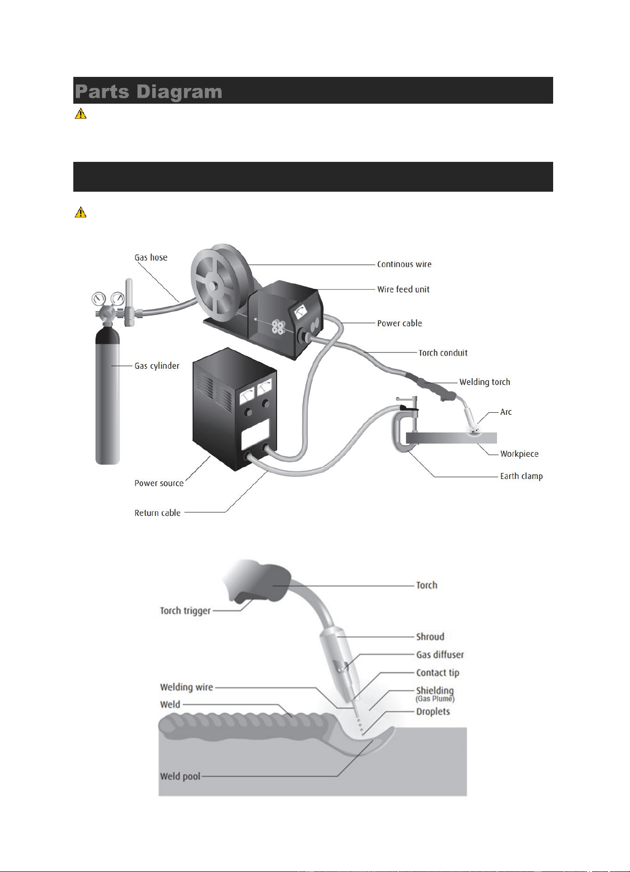
A Typical Metal inert gas (MIG) / Flux-cored arc welding (FCAW) and Metal-cored
Arc Welding (MCAW) setup
NOTE! The wire feed unit is shown separately for clarity. Most welders have wire feed units built into
the welder.
Downloaded from www.ManualsFile.com manuals search engine
Product Manual – Rossi Welders
110914123000
15
15
Rossi Welders
SUPER 200P AC/DC Welders
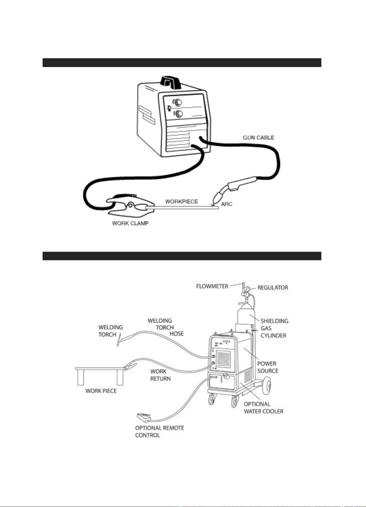
IMPORTANT! ARC Welding uses a negative ground (earth) connection. TIG / Plasma
Cut use a positive ground (earth).
IMPORTANT! This welder is fitted with overheating protection. If the welder overheats it
will go into protection mode and stop working with the O.C. indicator illuminated. If this
happens do not turn off the machine; leave it on so the welder’s internal fan can continue
running and cool the machine down. Once the O.C. indicator light shuts off you can
continue using your machine as normal.
ARC = Negative
Earth
TIG = Positive Earth PLASMA CUTTER =
Positive Earth
Downloaded from www.ManualsFile.com manuals search engine

Product Manual – Rossi Welders
110914123000
16
16
Rossi Welders
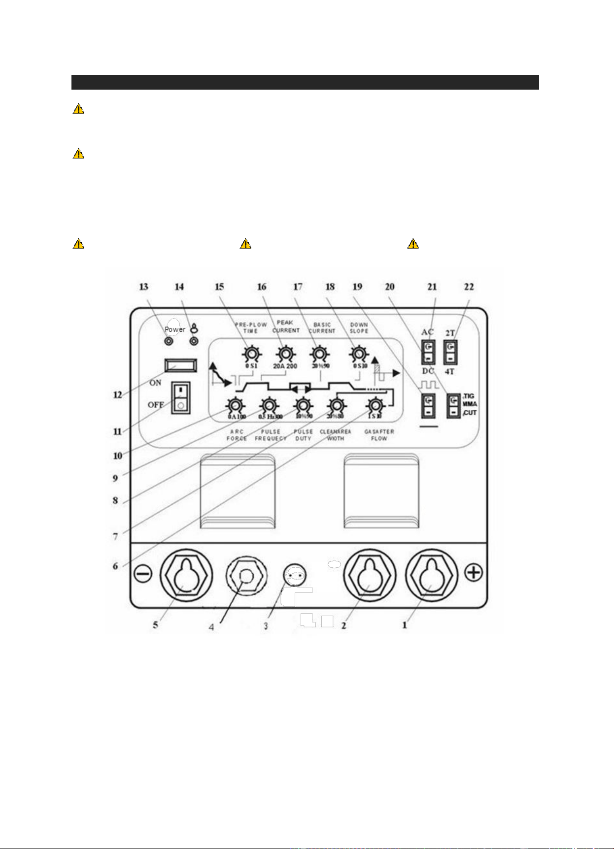
1. “TIG Earth” clamp connection & “ARC rod holder” connection.
2. “Plasma Earth” Clamp.
3. DIN Socket: High frequency start control.
4. “Plasma Torch” connection.
5. “TIG Torch” connection & “ARC earth” clamp connection.
6. Post flow (Gas): The length of time the torch gas flows after the arc terminates.
7. Clean area width (Phase Balance): Applies to AC welding and sets the proportion of time the weld current is
positive, during which time the current has an "oxide penetrating" effect on the aluminium alloy weld pool surface, but
which also tends to heat up and melt the tungsten electrode rather than the weld pool. Maximum heat is delivered to
the work piece/job when the electrode is negative so this setting is used to achieve the best compromise when
welding aluminium.
8. Pulse Duty (duty cycle): The number of minutes out of a 10-minute time period an arc welding machine can be
operated at maximum rated output. An example would be 60% duty cycle at 300 amps. This would mean that at 300
amps the welding machine can be used for 6 minutes and then must be allowed to cool with the fan motor running for
4 minutes.
9. Pulse Frequency: The sequencing and controlling of the amount of current, frequency and duration of the welding
arc.
10. Arc Force: This function enables operators to tailor the shape of the volt/amp curve to better suit the different joint
configurations and electrode types.
11. Main Power On/Off Switch.
12. Voltage display: Welding voltage display when machine is working. Only shows information when welder is in use.
13. Power indicator: Displays if power supply is on or off.
14. O/C: Overheating alert indicator, this can also indicate power issues.
15. Post Flow: The length of time the torch gas flows before the arc starts.
16. Peak current (pulse) – Peak current is the nominal current for the high energy pulse. It is adjusted to a level that is
set consistently above the globular to spray transition current. Peak current is expressed in units of ampere. During
the time when the peak current is delivered, the molten droplet detaches from the electrode. An increase in peak
current increases the average welding current and the weld penetration.
17. Basic current (Amperage): The amount of electricity flowing past a point in a conductor every second. Basic current
is background current and is the low side of the pulse (1/2, 1/4 or even 1/10 of the peak current).
18. Down-Slope Time: Allows the current to decrease at whatever rate you set on the knob.
19. Pulse/No Pulse switch: For thin welding plate and up-welding etc. place the switch at PULSE position (for normal
TIG welding set at no pulse).
20. Welding Process Selection: This button selects between MMA (ARC), TIG and CUT modes.
21. AC/DC Selector Switch: Select “AC” for Aluminium and Aluminium Alloys. Select “DC” for Stainless Steel, Steel,
and Cast Iron etc.
22. 2T/4T Switch:
2T: for using a switch on the torch handle…when you plug in the foot pedal or torch amperage control, most TIG
inverters are designed to bypass the 2t and 4t settings because the amperage control overrides all the upslope and
downslope. The 2t setting pretty much turns the torch switch into a 2 position switch. Press the switch, you get an
arc, release the switch, arc goes out.
4T: The 4T position is most always used in conjunction with upslope and downslope settings.
For example;
a) Press the button and you get an arc.
b) Release the button and set the arc up-slopes to whatever the main amperage is set to.
c) Press the button and arc down-slopes to lower amperage.
d) Release the button and arc stops.
e) Some machines are different but this is the general principle of 4t operation
Downloaded from www.ManualsFile.com manuals search engine
Product Manual – Rossi Welders
110914123000
17
17
Rossi Welders
TC-205 AC/DC Welders
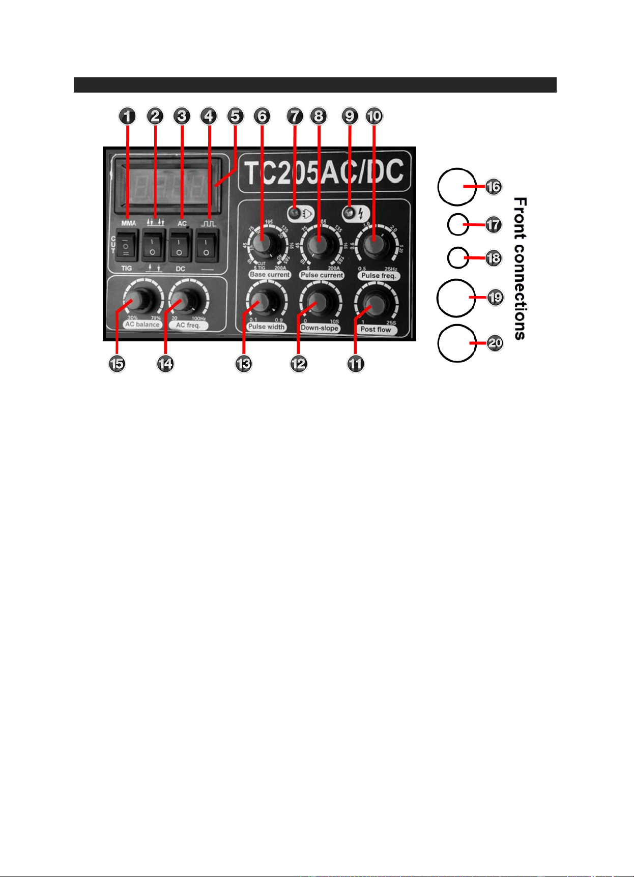
1. Welding Process Selection: This button selects between MMA/TIG and CUT modes.
2. 2T/4T Switch:
2T: for using a switch on the torch handle…when you plug in the foot pedal or torch amperage control,
most TIG inverters are designed to bypass the 2t and 4t settings because the amperage control overrides
all the upslope and downslope. The 2t setting pretty much turns the torch switch into a 2 position switch.
Press the switch, you get an arc, release the switch, arc goes out.
4T: The 4T position is most always used in conjunction with upslope and downslope settings.
For example;
a. Press the button and you get an arc.
b. Release the button and set the arc up-slopes to whatever the main amperage is set to.
c. Press the button and arc down-slopes to lower amperage.
d. Release the button and arc stops.
e. Some machines are different but this is the general principle of 4t operation
3. AC/DC Selector Switch: Select “AC” for Aluminium and Aluminium Alloys. Select “DC” for Stainless Steel, Steel,
and Cast Iron etc.
4. Pulse selector switch; Selection of the Pulse mode switch provides pulsed welding current output.
5. Voltage display: Welding voltage display when machine is working.
6. Base Current: - Set the amount of electricity flowing past a point in a conductor every second.
7. Power indicator: Displays if power supply is on or off.
8. Pulse Current: is the nominal current for the high energy pulse. It is adjusted to a level that is set consistently above
the globular to spray transition current. Peak current is expressed in units of ampere. During the time when the peak
current is delivered, the molten droplet detaches from the electrode. An increase in peak current increases the
average welding current and the weld penetration.
9. O/C: Overheating alert indicator, this can also indicate power issues.
10. Pulse Frequency: The sequencing and controlling of the amount of current, frequency and duration of the welding
arc.
11. Post Flow: The length of time the torch gas flows after the arc terminates.
12. Down-slope: Allows the current to decrease at whatever rate you set on the knob.
13. Pulse width: The time the high pulse amperage stays on. Also known as Pule % on time.
14. AC Frequency: The A/C frequency knob allows you to weld with a much higher frequency. That option stiffens and
focuses the TIG welding arc pinpoints the heat
15. AC Balance: This knob is used to balance DCEP (reverse polarity) and DCEN (straight polarity).
16. “TIG Earth” clamp connection & “ARC rod holder” connection.
17. Remote control connection
18. Torch Control connector
19. Cut Torch Gas Outlet
20. “TIG Torch” connection & “ARC earth” clamp connection.
Downloaded from www.ManualsFile.com manuals search engine
Product Manual – Rossi Welders
110914123000
18
18
Rossi Welders
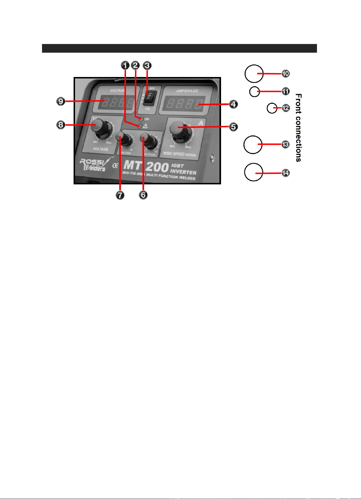
MT 200 Welders
1. O/C: Overheating alert indicator, this can also indicate power issues.
2. Power indicator: Displays if power supply is on or off.
3. Welding Process Selection: This button selects between MMA/TIG and CUT modes.
4. Amperage (current) display: Welding Amperage display during welding.
5. Wire Speed / Speed: The speed at which wire is fed out of the machine.
6. Arc Force: This function enables operators to tailor the shape of the volt/amp curve to better suit the different joint
configurations and electrode types. Higher settings make more dig and a "crisper" arc. Lower makes a smoother
arc.
7. Post flow (Gas): The length of time the torch gas flows after the arc terminates.
8. Voltage Adjustment.
9. Voltage display: Welding voltage display when machine is working.
10. Torch connection.
11. NA.
12. Wire feeder spool.
13. Positive connection.
14. Negative (Earth) connection.
Downloaded from www.ManualsFile.com manuals search engine
Product Manual – Rossi Welders
110914123000
19
19
Rossi Welders
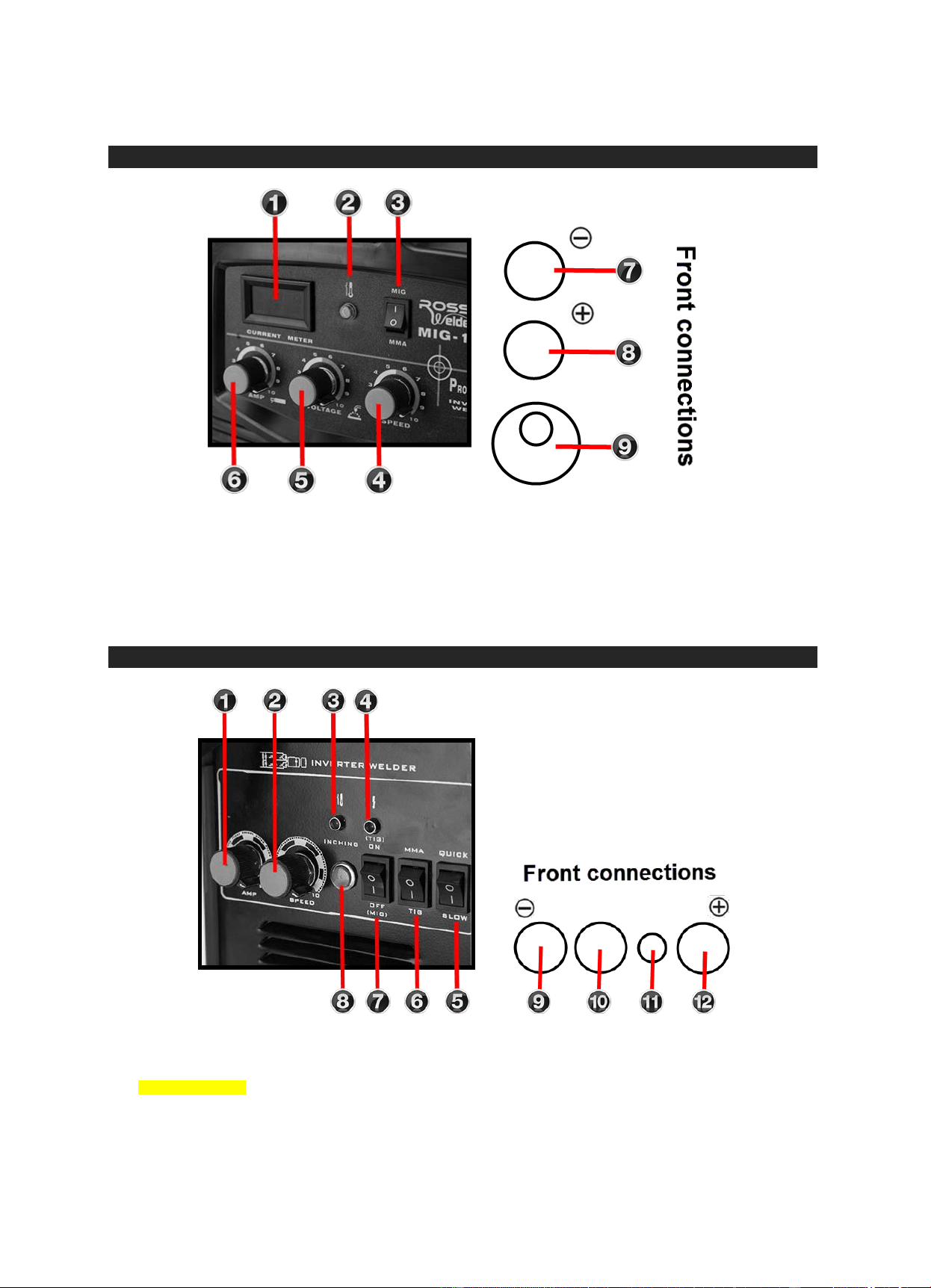
WELD-MIG185E Welders
1. Current (Amperage) display: Welding Current display during welding.
2. Overheating alert: This indicator, this can also indicate power issues.
3. Welding Process Selection: This button selects between MMA and MIG.
4. Wire Speed / Speed: The speed at which wire is fed out of the machine.
5. Voltage Adjustment
6. Amperage (current) Adjustment
7. Negative (Earth) connection.
8. Positive connection.
9. Torch connection.
WELD-MIG220BZ Welders
1. Amperage (current) Adjustment
2. Wire Speed / Speed: The speed at which wire is fed out of the machine.
3. Overheating alert: This indicator, this can also indicate power issues.
4. Power indicator: Displays if power supply is on or off.
5. Slow/Quick: -
6. Welding Process Selection: This button selects between MMA and TIG.
7. Welding Process Selection: This button selects between TIG and MIG.
8. Inching: This button helps feed wire through the MIG and Torch instead of doing so by hand.
9. Negative (Earth) connection.
10. Torch connection.
11. DIN High frequency out.
12. Positive connection.
Downloaded from www.ManualsFile.com manuals search engine
Product Manual – Rossi Welders
110914123000
20
20
Rossi Welders
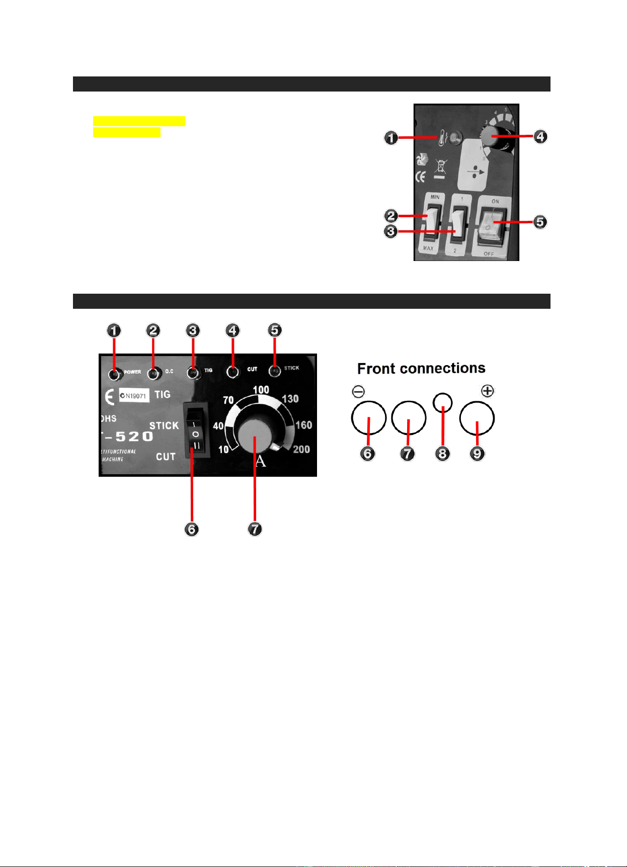
WLDMIG195RSSADJE, WLDMIG185RSSADJE & WLDMIG155RSSADJE Welders
1. Overheating alert: This indicator, this can also indicate power issues.
2. MIN/MAX switch: -
3. 1/2 switch: -
4. Wire Speed / Speed: The speed at which wire is fed out of the
machine.
5. Main Power On/Off Switch.
CT-520 Welders
1. Power indicator: Displays if power supply is on or off.
2. O/C: Overheating alert indicator, this can also indicate power issues.
3. TIG indicator: Indicates when TIG mode is enabled.
4. CUT indicator: Indicates when CUT mode is enabled.
5. STICK indicator: Indicates when STICK (ARC) mode is enabled.
6. Welding Process Selection: This button selects between TIG, STICK and CUT.
7. Amperage (current) Adjustment.
8. Negative (Earth) connection.
9. Torch connection.
10. DIN High frequency out.
11. Positive connection.
Downloaded from www.ManualsFile.com manuals search engine
Product Manual – Rossi Welders
110914123000
21
21
Rossi Welders
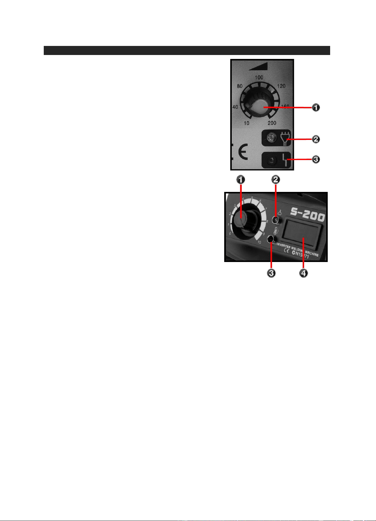
ROSSWELDER WELDER-S200 Welders
1. Amperage (current) Adjustment.
2. Power indicator: Displays if power supply is on or off.
3. O/C: Overheating alert indicator, this can also indicate power issues.
1. Amperage (current) Adjustment.
2. Power indicator: Displays if power supply is on or off.
3. O/C: Overheating alert indicator, this can also indicate power issues.
4. Amperage display: Welding Current display during welding.
Downloaded from www.ManualsFile.com manuals search engine
Product Manual – Rossi Welders
110914123000
22
22
Rossi Welders
Which welder do I need?
Unfortunately, there is no single welding process suitable for all applications, so let’s begin with an
overview of the basic processes and highlight the capabilities and advantages of each. This will help
us better match a process to your specific needs. If you have previous welding experience, feel free to
skip ahead. If you are somewhat of a novice, this section will provide you with a better understanding
of the types of welders available, how each performs and degree of welding skill required to operate
each. In addition, we’ll offer examples of specific applications best suited to each process.
Types of Welding
The most common welding processes include Stick, MIG/Flux-cored and TIG. Each process has its
own unique set of benefits and limitations, works well in some welding applications, and not well in
others.
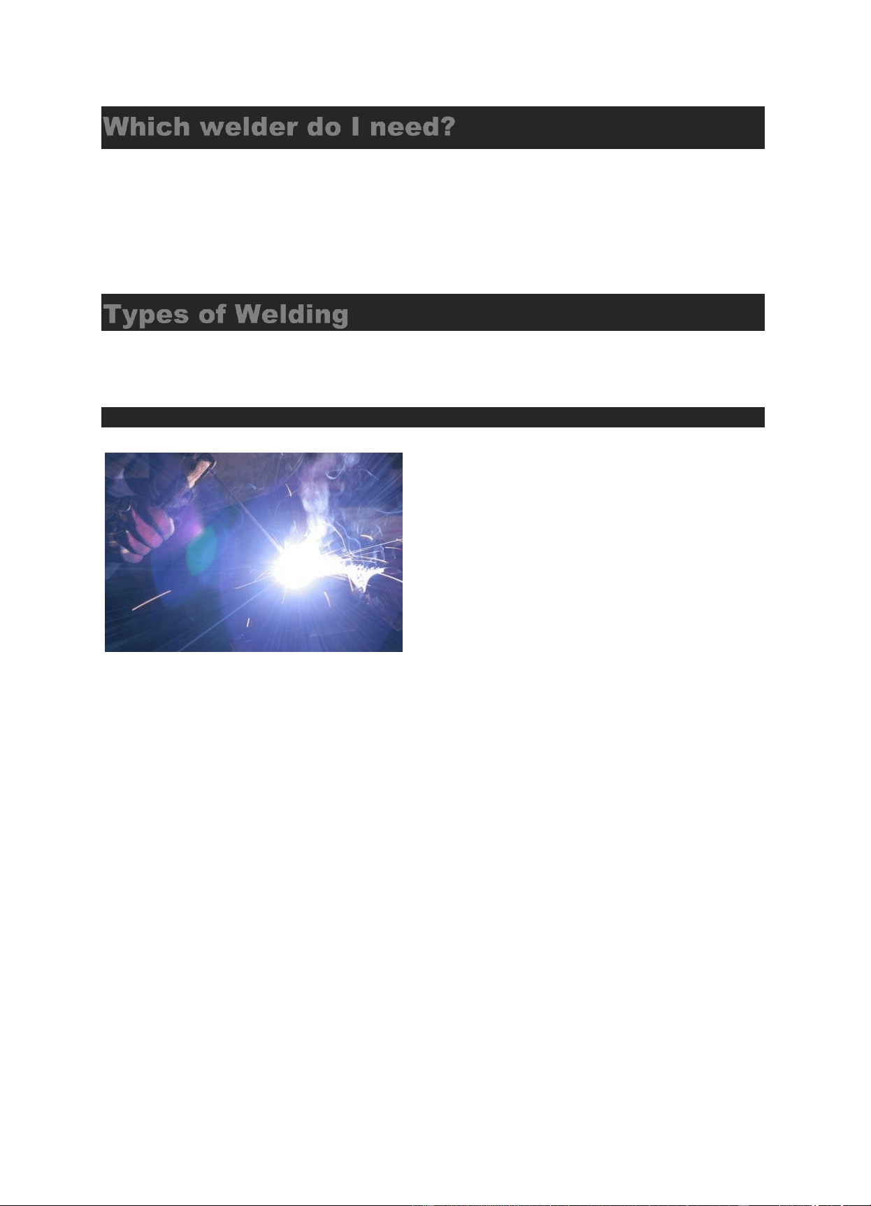
ARC / Stick Welding
Arc welding is the process of using
electrodes to fuse two pieces of metal.
Better suited for windy, outdoor conditions
More forgiving when welding on dirty or rusty metal
Works well on thicker materials
If you learned to weld years ago, you likely learned
using an arc welder. Stick welding has, for many
years, been the most popular method for most home-
shop welding needs. Stick welding uses an electric
current flowing from a gap between the metal and the welding stick, also known as an arc-welding
electrode. Stick welding is an effective method for welding most alloys or joints and can be used both
indoors and outdoors, or in windy areas. It is also the most economical welding method and largely
popular because of its ability to create an effective bond on rusty or dirty metals.
Arc welding is limited, however, to metals no thinner than 18-gauge, requires frequent rod changing,
emits significant spatter; and welds must be cleaned upon completion. Stick welding is also more
difficult to learn and use, particularly the ability to strike and maintain an arc. Arc welders are available
in either AC or DC or AC/DC; with AC being the most economical. It is used for welding thicker metals
of 1/16-inch or greater.
Downloaded from www.ManualsFile.com manuals search engine
Product Manual – Rossi Welders
110914123000
23
23
Rossi Welders
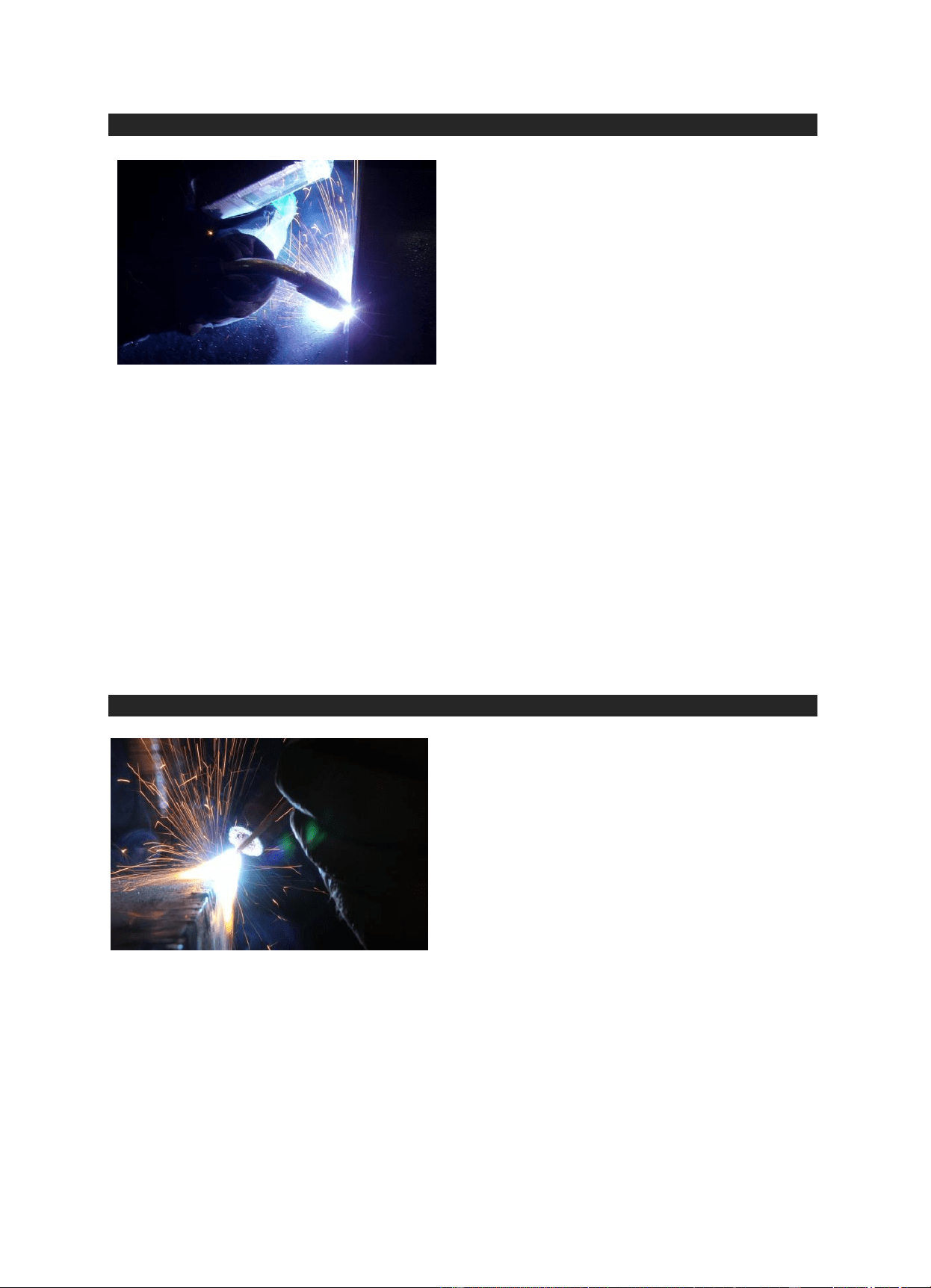
MIG Welding / Gas Metal Arc Welding (GMAW)
MIG Welding is the process of using
welding wire either with or without
shielding gas to fuse two pieces of
metal.
Easiest process to learn
High welding speeds possible
Better control on thinner metals
Cleaner welds possible with no slag to clean
Same equipment can be used for Flux-Cored Welding
MIG welders use a wire welding electrode on a spool that is fed automatically at a constant pre-
selected speed. The arc, created by an electrical current between the base metal and the wire, melts
the wire and joins it together with the base, producing a high-strength weld with great appearance and
little need for cleaning. MIG welding is clean, easy and can be used on either thin or thicker plate
metals.
A slight variation of MIG welding — Flux-Cored Arc Welding (FCAW) — is similar in that it is also a
wire-feed process but differs in that it does not require a shielding gas. This gas-free welding
application uses Flux-Cored wire to shield the arc, and is a simple, efficient and effective welding
approach, especially when welding outdoors, in windy conditions or on dirty materials. The process is
widely used in construction because of its high welding speed and portability.
Both MIG and Flux-Cored are very easy to learn and can create extremely clean welds on steel,
aluminium and stainless. Both types have the capability to weld materials as thin as 26-gauge.
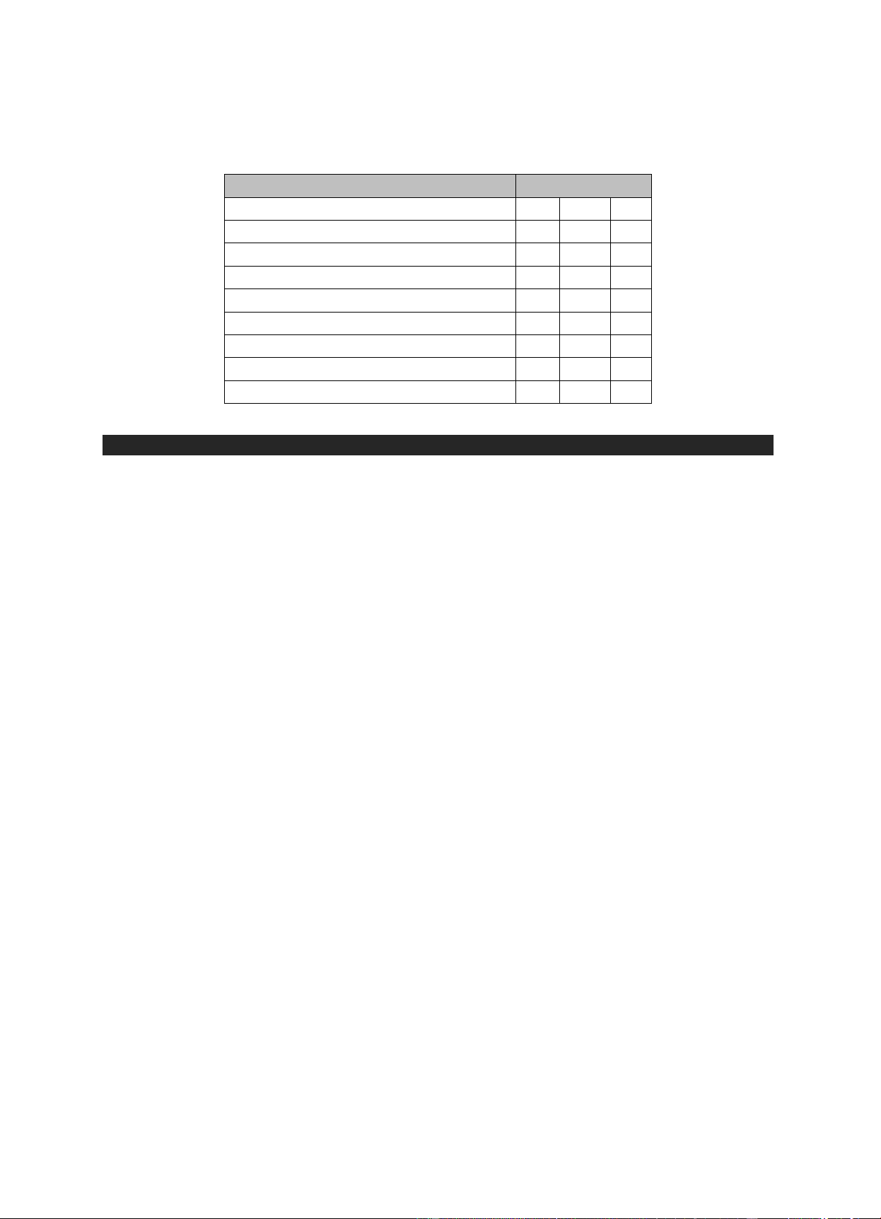
TIG Welding / Gas Tungsten Arc Welding (GTAW)
TIG Welding is the process of using a
tungsten-electrode and inert gas to fuse
two pieces of metal
Provides highest quality, precise welds
Highly aesthetic weld beads
Allows adjustment of heat input while welding by use of
a foot control.
TIG welding is an arc welding process that uses a
non-consumable tungsten electrode to produce the weld. The weld area is protected from
atmospheric contamination by a shielding gas (usually argon), and a filler metal, though some welds,
known as autogenous welds, do not require it. A constant-current welding power supply produces
energy that is conducted across the arc through a column of highly ionized gas and metal vapours
known as plasma.
TIG welding is most commonly used to weld thin sections of alloy steel, stainless steel and non-
ferrous metals such as aluminium, magnesium, and copper alloys. The process grants the operator
greater control over the weld than other welding processes, allowing for stronger, higher quality
welds. TIG welding is comparatively more complex and difficult to master than other welding types,
and is significantly slower.
Downloaded from www.ManualsFile.com manuals search engine
Product Manual – Rossi Welders
110914123000
24
24
Rossi Welders
The chart below identifies which weld process you can use for each type of metal. Keep in mind that many of these materials
are also processed using varying combinations of two or more metals, a process that is helpful to reinforce strength and
functionality.
Metal
Weld Process
MIG
Stick
TIG
Steel
●
●
●
Stainless Steel
●
●
●
Aluminium Alloys
●
●
Cast Iron
●
Chromoloy
●
Copper
●
Brass
●
Exotic metals (Magnesium, Titanium, etc.)
●
Pulsed TIG Welding
Pulsed TIG Welding Reduces Heat Input and Warping on Stainless Steel for example stainless steel
exhausts.
Pulsed TIG lowers heat input; increases precision and quality.
High-speed pulsing constricts and focuses the arc, which increases arc stability, penetration and travel speed,
while producing a smaller heat affected zone.
Lower heat input minimises distortion and improves weld quality.
TIG Welding at Warp Speed—Without the Warping!
Every TIG welding machine is slightly different but the concepts are basically the same. There are 4
basic settings to understand:
Pulsed TIG welding requires setting four variables: Peak amperage, Background amperage,
Peak time and Pulse rate. Determining good values for setting peak amperage works much the
same as setting maximum amperage values for regular DC TIG: use 1 amp for every .001 in. of
thickness.
The peak time is simply the percentage of time during one pulsing cycle the power source spends at
the peak amperage (main amperage). With peak time of 80 percent and a pulse rate of 1 pulse per
second (PPS), the inverter will spend 8/10ths of a second at peak amperage and 2/10ths of a second
at the background amperage. Increasing the peak time percentage adds more heat to the part, while
decreasing peak time percentage reduces heat. As general rule of thumb, begin experimenting at 50
to 60 percent peak time.
The background amperage will be a percentage of the main amperage set on the machine. Thus, a
machine set for an output of 150 amps and background amperage of 30 percent produces a
background amperage output of 45 amps. Lowering the background amp percentage reduces the
average heat input, while increasing the background amp percentage raises the overall amperage.
Especially notice how background current adjustments affect weld puddle fluidity. As a rule, use
enough background current to shrink the puddle to about half its normal size while still keeping the
puddle fluid. When welding stainless and carbon steels, start by setting the background amperage at
20 to 30 percent of peak amperage.
Pulse frequency per second (PPS) is simply how many times the machine will complete one pulsing
cycle in a time span of one second. Increasing the number of pulses per second produces a smoother
Downloaded from www.ManualsFile.com manuals search engine
Product Manual – Rossi Welders
110914123000
25
25
Rossi Welders
the ripple effect in the weld bead, narrows the weld bead and adds more “cooling effect.” Reducing
the number of pulses per second widens the weld bead. Slower pulsing also helps agitate the puddle
and release any porosity or gas trapped in the weld (this is very helpful when welding aluminium with
AC pulsed TIG).
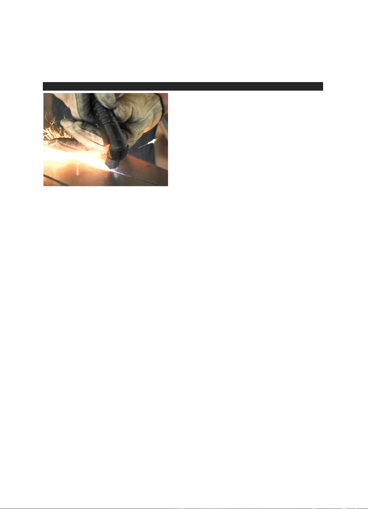
Plasma Cutting
Plasma cutting is the use of high velocity
jet of ionised gas to cut through metal.
Much faster than mechanical cutting
Neater and more versatile than Oxy cutting
Can cut a thickness up to 25mm (1”)
Can cut through a larger range of material than Oxy
cutting
Plasma cutting is a process that uses a high velocity
jet of ionized gas that is delivered from a constricting
orifice. The high velocity ionized gas, that is, the
plasma, conducts electricity from the torch of the plasma cutter to the work piece. The plasma heats
the metal, melting the material. The high velocity stream of ionized gas mechanically blows the molten
metal away, severing the material.
Plasma cutting is ideal for cutting steel and non-ferrous material less than 1 inch thick. Oxy cutting
requires that the operator carefully control the cutting speed so as to maintain the oxidizing process.
Plasma is more forgiving in this regard. Plasma cutting really shines in some niche applications, such
as cutting expanded metal, something that is nearly impossible with oxy. And, compared to
mechanical mean of cutting, plasma cutting is typically much faster, and can easily make non-linear
cuts.
Downloaded from www.ManualsFile.com manuals search engine

Product Manual – Rossi Welders
110914123000
26
26
Rossi Welders
Getting Started
IMPORTANT! The actual Earth can vary from positive to negative depending on the type
of function / machine you are using! Be sure to check you have configured your welder
with the correct earthing terminal before starting your project.
TIG Welders generally use a positive earth – please check and understand your
equipment before use.
TIG welding Basics
Tungsten - For welding steel the tungsten should be ground to a long point with the taper length
about 2 or 3 times the diameter of the tungsten. The long taper and sharp tip improves arc stability.
For a butt weld or open corner weld the stick out would be about 5-6mm.
Gas Shrouds - For general purpose work on steel a number 7 shroud is a good compromise. A
smaller number 4 shroud would be more suitable for fillet welds, and larger shrouds might be used for
aluminium, the larger the shroud the better the gas coverage.
Shielding Gas - Pure Argon is normally used as a TIG shielding gas and is suitable for both steel and
aluminium welding. The shielding gas must be completely inert - MIG shielding gasses cannot be
used as the CO2 would cause the tungsten to oxidise.
Flow Rate - Flow rate will generally be 6 to 7L/min. The rate might be increased slightly to
compensate for windy conditions. TIG uses a lot of shielding gas so it pays to set up the gas flow
accurately. A flow meter attached to the regulator will give a more accurate flow reading than the
gauge on the regulator, or a peashooter type flow meter can be used to measure flow at the torch.
Post-Flow Time - Post flow protects the tungsten and the weld as they cool. The tungsten will take
longer to cool from higher amps, and a rough rule of thumb is to increase post flow time by 1 second
for every 10 amps. Most basic work uses a post flow of 4-5 seconds.
Polarity - DC TIG Welding is carried out with the torch negative and the work positive. That is also
known as DCEN (DC electrode negative) or "straight" polarity for those with older welders. About two
thirds of the heat goes to the positive side or the arc. For TIG the negative torch helps avoid
overheating the tungsten.
Downloaded from www.ManualsFile.com manuals search engine
Product Manual – Rossi Welders
110914123000
27
27
Rossi Welders
ARC Welding Basics
Arc welding (short for Manual Metal Arc (MMA) welding and also known as Stick and SMAW) is a very
involved subject and this below information is only a basic introduction.
Arc Welding Safety - As with any other electric welding process, skin and eyes need to be properly
protected from UV light. Electric shock, fumes, burns, and fire are other risks.
The safety page discusses how to minimise these risks.
Starting the Arc - The arc is started by touching the electrode momentarily against the work to
complete the electrical circuit before raising the electrode to establish the arc.
'Tap starting' and 'scratch starting' are the two common methods of starting the arc. Which one to use
is a personal preference, and can be influenced by rod and welder type.
Rod Position, Arc Length and Movement - Arc welding takes some effort to learn, and it
is very sensitive to the position of the work.
Rod Angle – For welding on the flat work piece the rod should be angled 10 to 20 degrees from vertical and pulled in
the direction of the arrow. The angle of the rod prevents the slag overtaking the rod (welding over slag would cause
inclusions in the weld). It's OK to support the top of the electrode with your spare hand and this improves control of
the electrode. Electric shocks aren't a problem, but be careful to reposition your hand away from the heat before the
electrode gets too short.
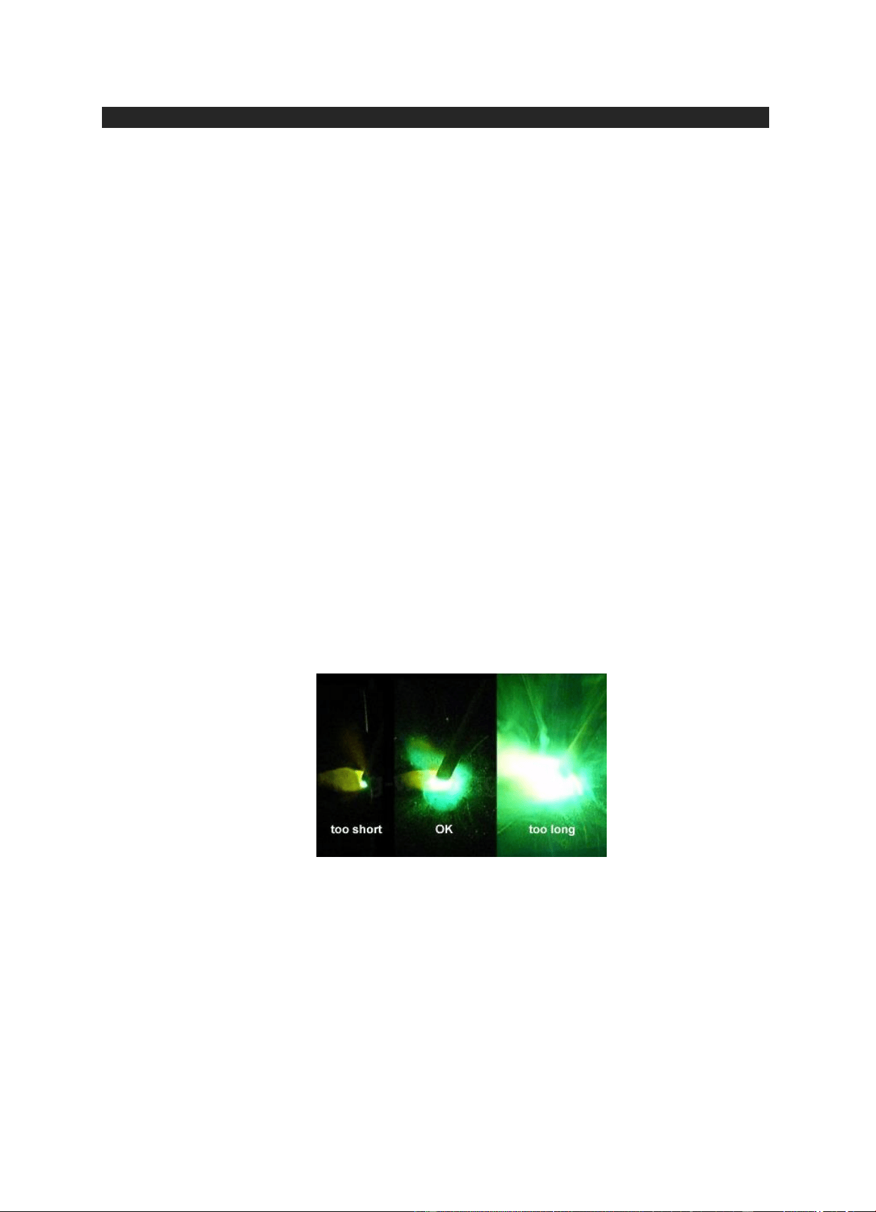
Arc Length – The arc length is the distance between the electrode and the weld pool. It should be roughly the same
as the diameter of the rod. This is nowhere near as straightforward as it sounds. The weld pool will also be hidden by
molten slag. To achieve the correct arc length using 3.2mm rods the distance between the flux coating on the rod
and the flux on top of the weld might be less than 1mm.
Arc welding faults - When learning any new process you'll likely start off doing things wrong.
Typically the faults encountered are caused by the following:
- Incorrect travel speed
- Incorrect arc length
- Incorrect amps.
Flat Joints and Joint Preparation - Arc welding is especially suitable for joining thick material as
cold joins are easy to avoid. That makes it possible to tackle thicker material using multiple passes of
weld.
Fillet Joints – Filet Joints are beyond the scope of this manual.
Downloaded from www.ManualsFile.com manuals search engine
Product Manual – Rossi Welders
110914123000
28
28
Rossi Welders
Installing MIG wire
IMPORTANT! MIG welders are very sensitive to wire feeder settings and liner condition.
The wire liner is a service item and should be replaced regularly especially if rusty wire
has been run through it.
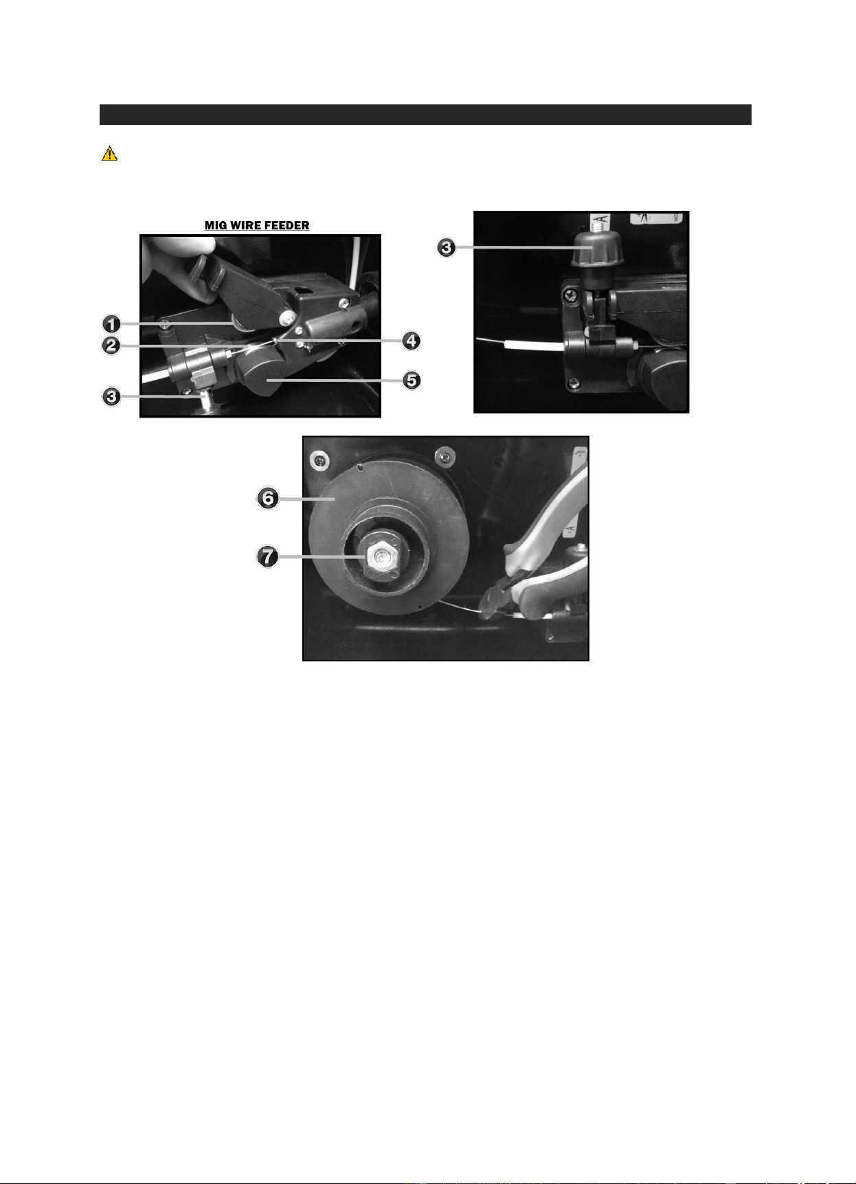
1. Wire Feed Tensioner
2. Wire roller (change to suit wire diameter)
3. Feed tensioner adjuster knob.
4. Wire Sleeve
5. Wire roller locking cap
6. Wire Spool
7. Wire spool spring tensioner
Preparing the wire - The wire reel mounting normally includes a spring tensioner. This tensioner
should be initially tightened to the point where the reel of wire doesn't unravel under its own spring
tension.
The first 3 inches of wire should be as straight as possible to reduce the chance of damage to the
liner or snagging as the wire is fed through. Sharp wire cutters can be used for trimming.
Letting go of the end of the wire would cause it to unravel and tangle.
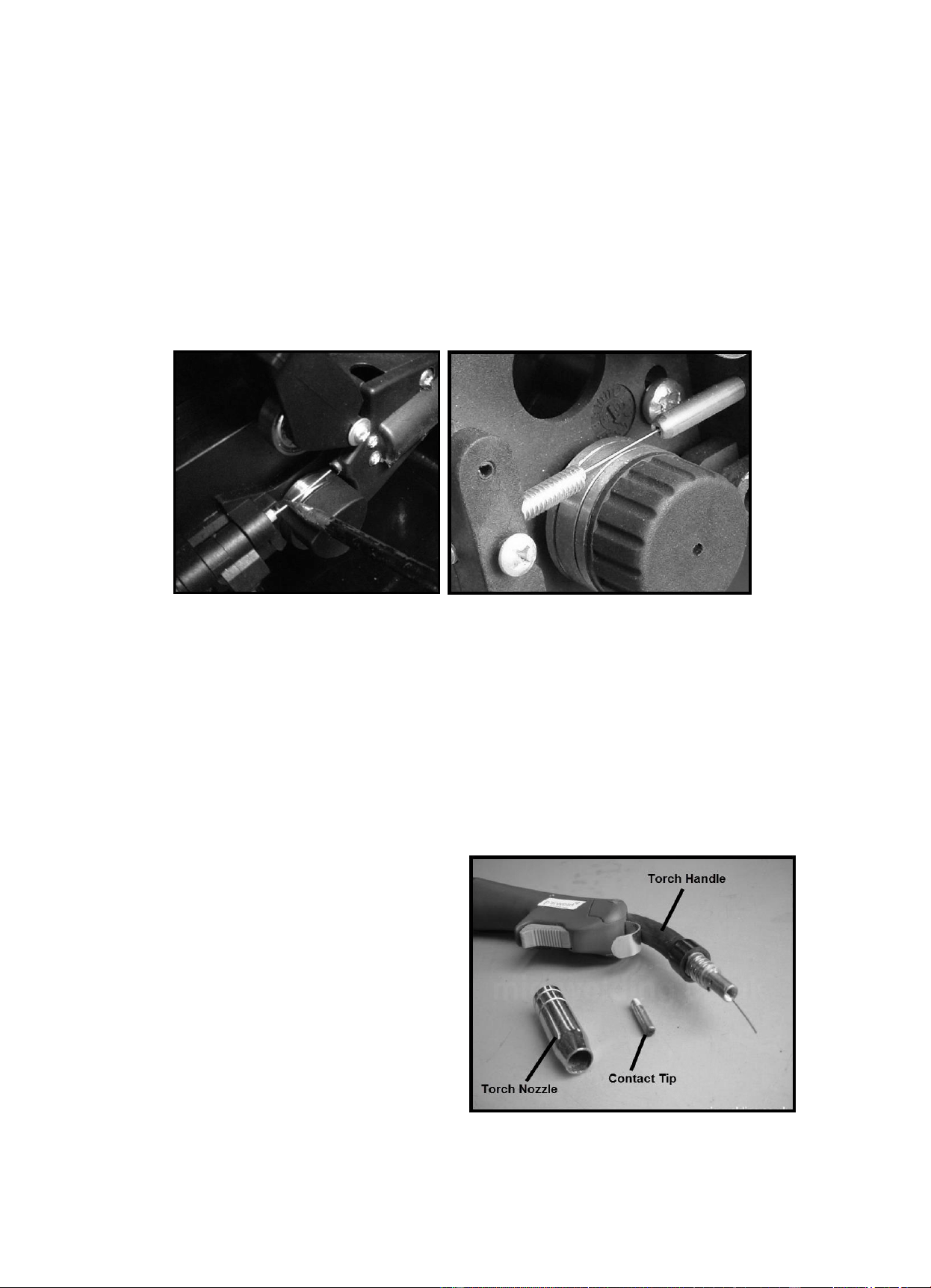
Feeding the wire to the torch - The wire is inserted through the guide tube and over the roller. On
the torch side of the welder the small hole of the end of the wire liner should be visible. The end of the
wire can be aligned with that hole using a small screwdriver or the piece of wire that was removed at
the start.
The wire can then be pushed into the liner manually for a few inches, and should feed easily and
without any force. If force is required it is likely that the wire has missed the liner.
Downloaded from www.ManualsFile.com manuals search engine
Product Manual – Rossi Welders
110914123000
29
29
Rossi Welders
The wire feed roller itself will normally have two grooves, and is secured either by a grub screw in the
side of the roller, or a knurled plastic cap as in the photo. The groves on welders are normally
matched to 0.6mm, 0.8mm and 1mm wire and the roller can be reversed / swapped to line up the
appropriate groove for the wire size being used.
Rust or grease on the wire can reduce the effectiveness of the rollers, and they need to be cleaned
with a dry cloth before inserting the wire.
With the wire pushed a couple of inches into the liner replace the tensioner clamp, switch on the
welder and use the wire feed mechanism to push the wire through the liner. The torch should be a
straight as possible especially near the torch to reduce the chance of the end of the wire catching
inside the liner.
On some welders it can help to remove the contact tip from the end of the torch before feeding the
wire through. The gas shroud is secured by a spring and can be removed by pulling and twisting in a
clockwise direction, and the tip has a standard screw thread that unscrews in an anti-clockwise
direction. Never unscrew the tip when it is still hot or it may break or strip the thread inside the torch.
If the wire snags in the torch it may be possible to withdraw a little wire onto the reel, and use a
rotating motion with the torch to get the wire past the snagging point.
Setting the roller tensioner - The wire is driven by friction between the wire feed drive roller and the
wire. Care in tensioning the wire feed can prolong the life of the tensioner mechanism.
Tightening the tensioner fully can cause the tensioners or tensioner mountings to bend and could also
shear the motor gear if the wire were to stick in the tip during welding. The minimum tension that will
ensure good wire feed is recommended.
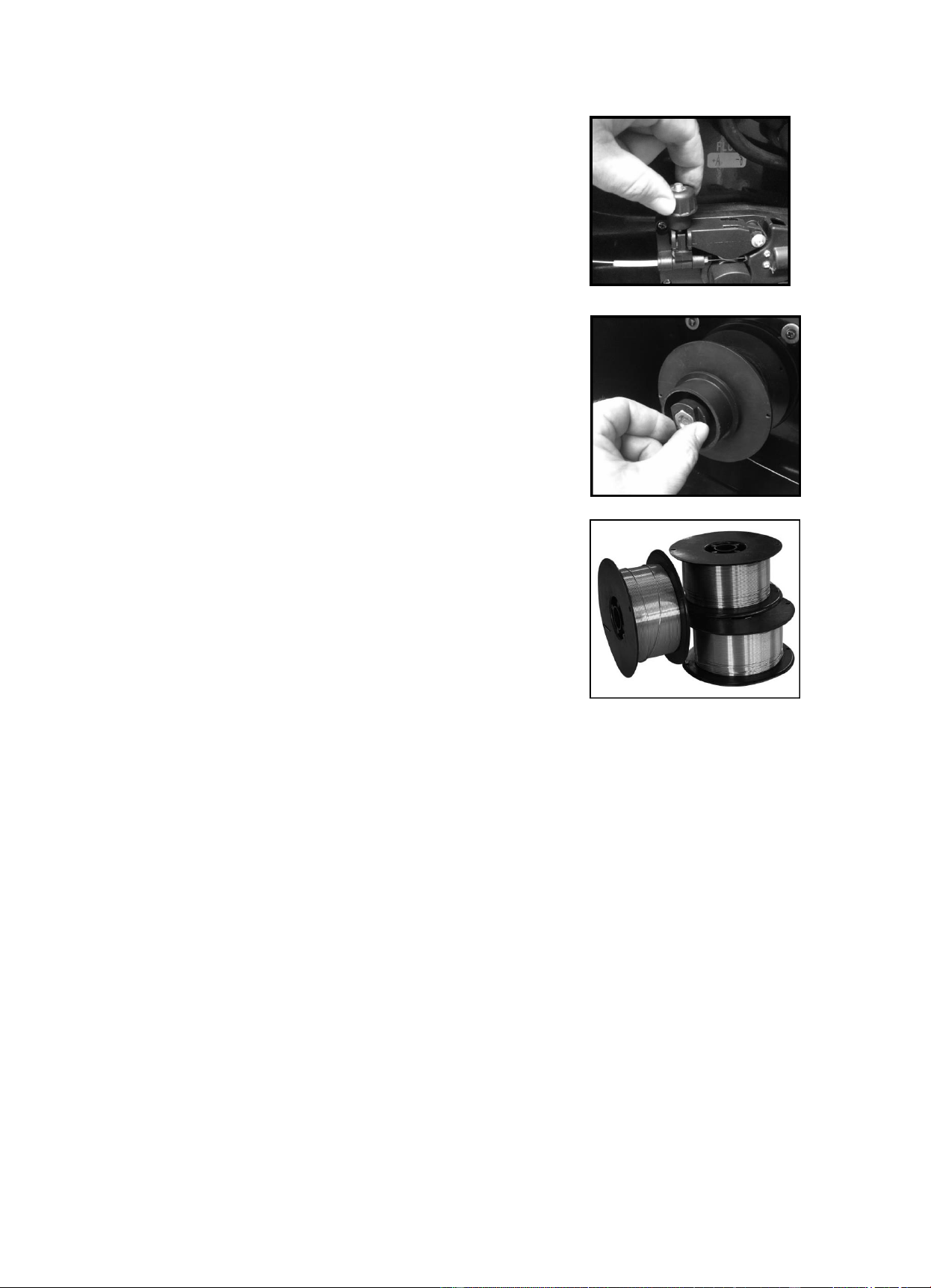
One way to judge the wire feed tension is to grip
the wire very lightly between your fingers and pull
the trigger. Care is needed with this approach as
if the wire were to touch the earth clamp it would
arc, resulting in burned fingers and possibly arc
eye.
Starting with very little tension on the wire feed
mechanism, Increase the tension until the wire
feed stops slipping, but do not grip the wire so
tightly that the wire feed motor slows.
The wire should ideally start to slip inside the
rollers before the motor stalls.
Downloaded from www.ManualsFile.com manuals search engine
Product Manual – Rossi Welders
110914123000
30
30
Rossi Welders
Setting the reel tensioner - Finally check the tension on the wire
reel. The tensioner on the reel is there to stop the wire becoming
loose and tangled, but the tension should be as light as possible to
make life easy for the wire feed mechanism.
Set your wire speed to the maximum you are likely to use, and
press the trigger on the torch. The wire reel should stop without
unravelling when you lift off the trigger.
Avoiding wire feed problems - Wire feed problems are commonly
caused by rusty welding wire. The rust acts as a lubricant on the
feed rollers causing slip, and as an abrasive on the wire liner which
increases resistance.
Wire can quickly go rusty when left unused inside a welder. Ideally
the wire should be removed and stored indoors when the welder is
not in use. This wire in the photo was reusable after the top couple
of layers of wire had been removed. Liners damaged by rusty wire
can be replaced fairly cheaply.
Other wire feed info - Wire liners do wear and are considered to
be a service item. Professional welders might replace the liner after
every 100kg of wire. On most welders the liner can be unscrewed
at each end and pulled out of the cord.
Downloaded from www.ManualsFile.com manuals search engine
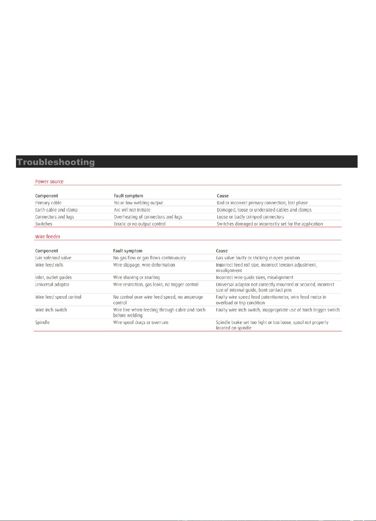
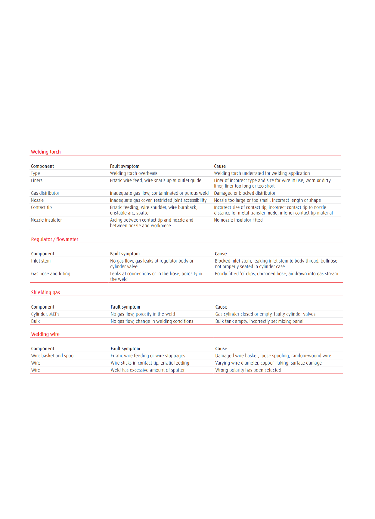
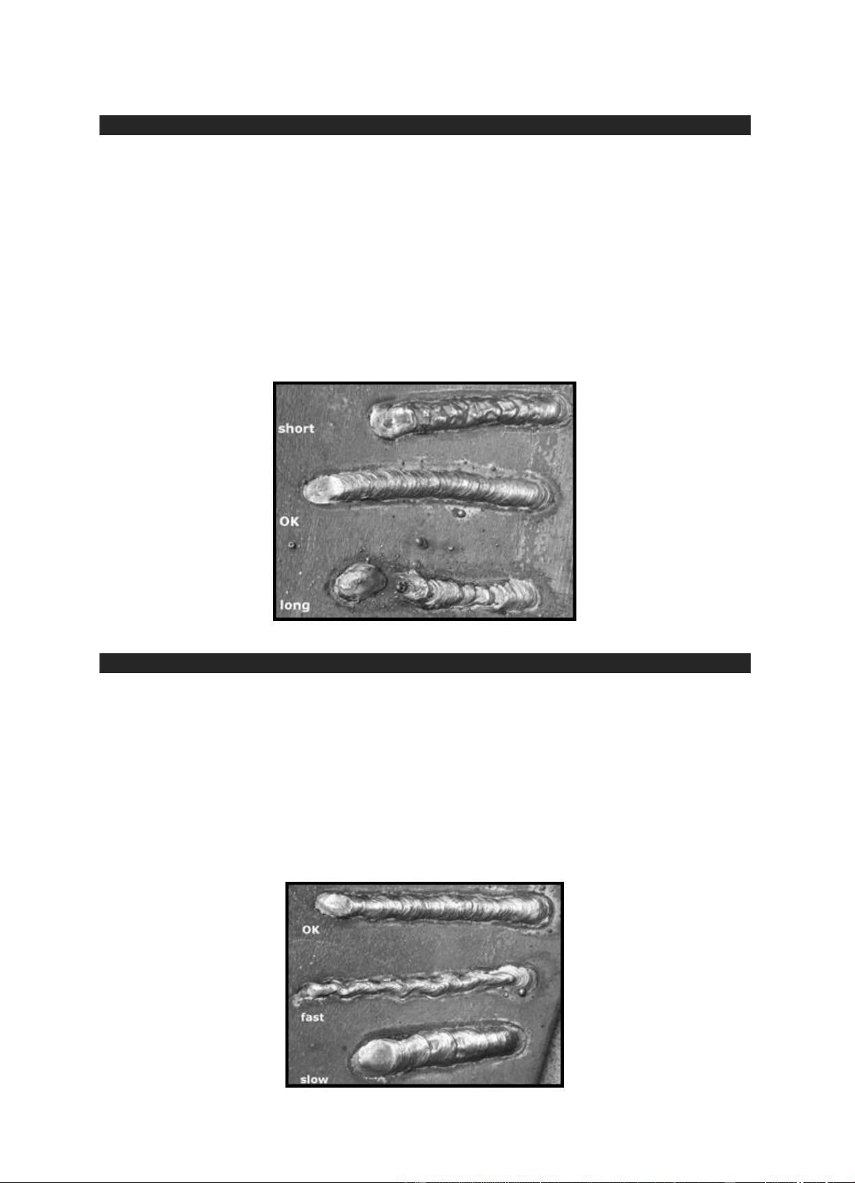
Product Manual – Rossi Welders
110914123000
33
33
Rossi Welders
Arc Welding Faults
Arc Length Too Short
This weld was laid with the end of the rod covered by the molten slag. The surface of the weld is
uneven where it has been dragged along by the rod, and the weld will be low on power and contain
slag inclusions.
Arc Length is OK.
This is a normal arc weld. The weld has a consistent profile and minimal spatter.
Arc Length Too Long
Too great a distance between the rod and the work will increase the voltage resulting in a flat and
wide weld with a great deal of spatter. It also makes the arc unstable, and the slag will be difficult to
remove from the edges of the weld. Sectioning this weld reveals undercutting to the left side.
Travel Speed Faults
Speed is OK. - The bead is fairly consistent. The ridges in the weld are semi-circular.
Speed Too Fast - Excessive speed results in a thin, weak bead. The ridges in the weld are elongated
and triangular. Had the current been increased to compensate for the speed the ridges would still
remain elongated.
Speed Too Slow - Welding too slowly results in a wide tall build-up of weld. The shape of the weld is
not consistent as the weld pool has built up and then collapsed into the crater. The poor control of the
weld pool can result in cold joints and slag inclusions.
Downloaded from www.ManualsFile.com manuals search engine
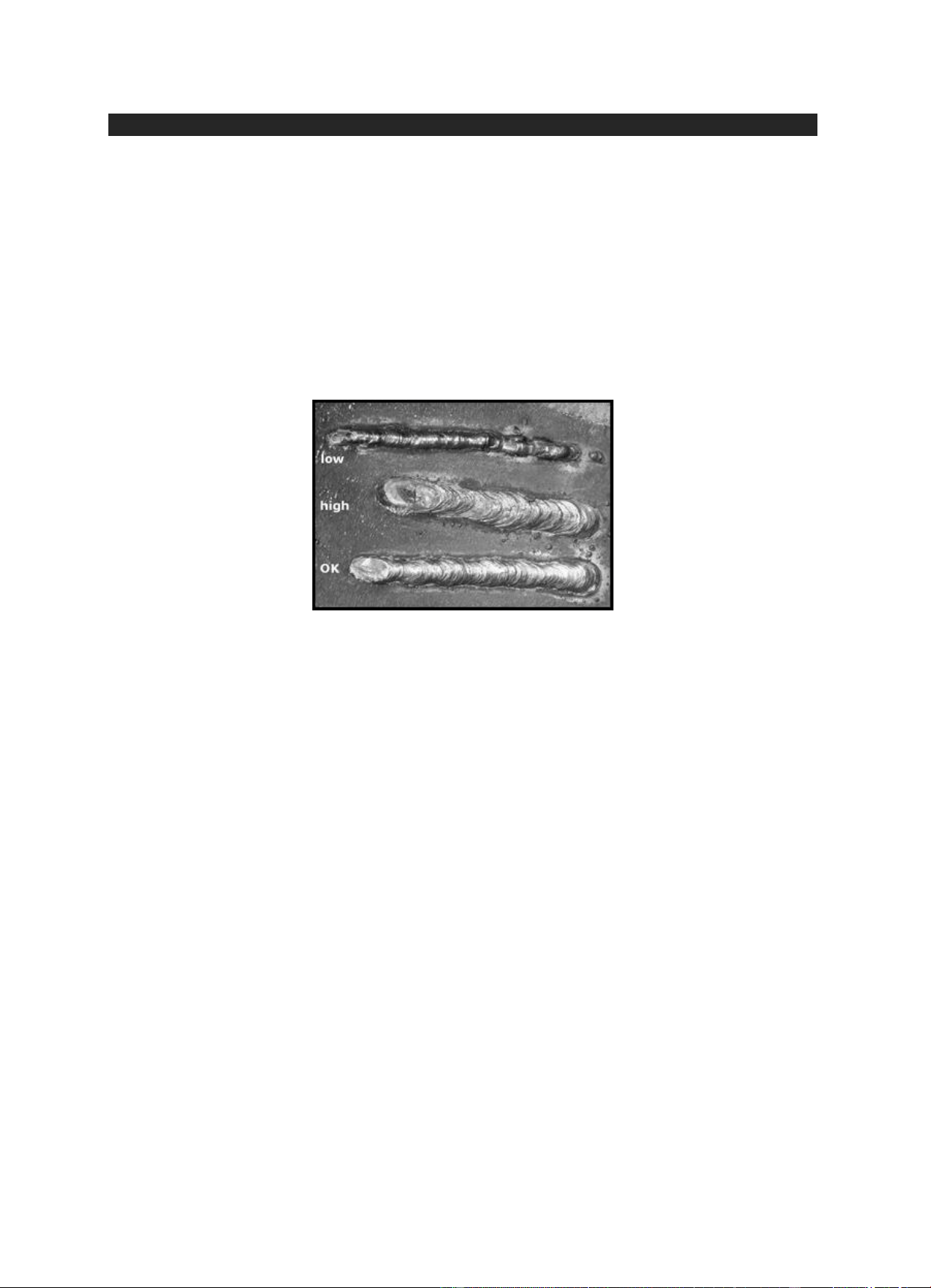
Product Manual – Rossi Welders
110914123000
34
34
Rossi Welders
Current Setting Faults
Amps too low - Setting the amps too low will result in a tall, narrow bead lacking in penetration. The
weld will be difficult to start and the arc prone to straying towards one side of a joint in preference to
the other.
Amps too high - The bead is wide, flat and irregular, and a small undercut can be seen on the right
of the weld in the sectioned photo. A deep crater has formed at the end of the weld, and the slag is
difficult to remove from the edges of the weld.
Excessive current should not be compensated by excessive travel speed. This can result in slag
inclusions due to rapid cooling of the weld.
Amps are OK. - With the amps set correctly the bead is a consistent rounded shape, and the slag is
easy to remove.
Downloaded from www.ManualsFile.com manuals search engine
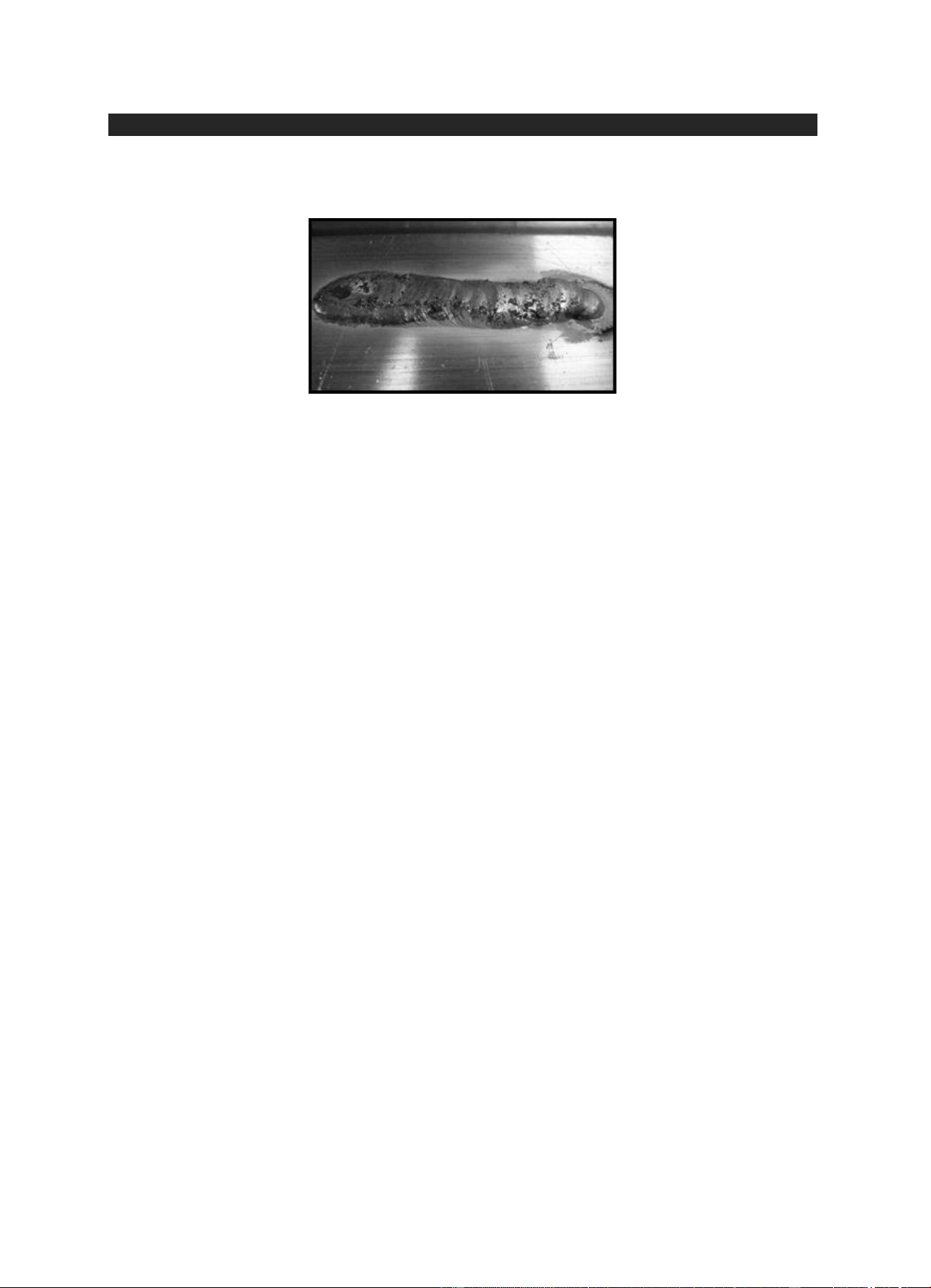
Product Manual – Rossi Welders
110914123000
35
35
Rossi Welders
TIG Welding Faults
Poor Gas Coverage Leads to Contamination - The shielding gas is not turned on, there is either too
little or too much gas shielding, or the gas shielding is blown away.
Check the gas cylinder label to be sure you’re using the right type of gas for TIG welding, generally
100 percent argon (or perhaps an argon/helium blend for thick aluminium). Attempting to weld with an
AR/CO2 mix (used for MIG welding) will cause immediate contamination.
Set the proper gas flow rate, which should be 15 to 20 cubic feet per hour (cfh). Welders
commonly—and incorrectly—assume that a higher gas flow/pressure provides greater protection. In
fact, excessive gas flow creates turbulence and swirling currents that pull in unwanted airborne
contaminants (and it can cause arc wandering).
Check all the fittings and hoses for leaks. Any breach may pull air into the shielding gas stream,
which can cause the weld to be contaminated (and you’ll waste money if gas escapes). Rub soapy
water over the hose and all fittings. If bubbles form, you have a leak and need to replace the defective
components. You may have a tank contaminated with moisture. Check with your gas supplier to
resolve this issue.
Downloaded from www.ManualsFile.com manuals search engine
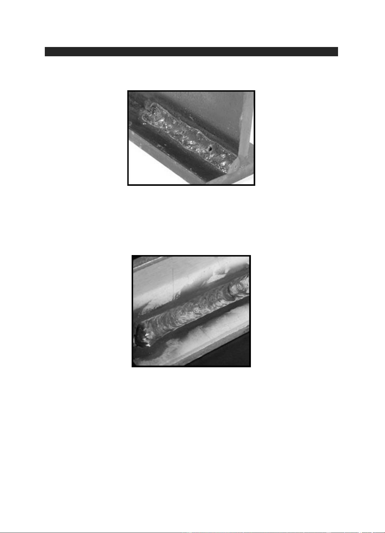
Product Manual – Rossi Welders
110914123000
36
36
Rossi Welders
MIG Welding Faults
No Shielding Gas on Steel - A lack of or inadequate shielding gas is easily identified by the porosity
and (pinholes) in the face and interior of the weld.
On aluminium, a sooty looking weld can be caused by using a drag vs. a push technique. The soot
can be removed, but cutting the weld open will reveal pinholes where impurities are trapped in the
weld. Aluminium builds up an oxide that needs to be removed before welding. Wire brushing is the
most common method of cleaning aluminium, but it needs to be done with a stainless steel brush to
avoid contaminating the weld with the impurities of a steel brush. Push vs. drag technique. On steel,
either pushing or dragging the gun is acceptable, but with aluminium, the drag technique will lead to
weld defects.
Lack of Fusion: Lack of fusion can occur when the voltage or wire feed speed is set too low, or when
the operator's travel speed is too fast. Because aluminium conducts heat much faster than steel, it is
prone to lack of fusion at the start of a weld until enough energy is put into the weld. Some welding
equipment addresses this by automatically ramping up the current at the start of a weld and then
decreasing it to avoid too much heat build-up.
Craters: With aluminium, craters can form at the end of a weld. If they are not filled in, they create a
stress point, which can lead to cracking. This requires the user to quickly trigger the gun again to fill in
the crater, although some welding machines offer a crater timer that will fill in the crater when the gun
trigger is released.
Burn Through: Too much heat input can be caused by setting voltage or wire feed speed too high or
by too slow of a travel speed. This can lead to warping or burn through especially on the thinner
materials found in the sign industry, aluminium being more prone to the effects than steel. Generally
aluminium requires a faster travel speed than steel to avoid heat build-up.
Downloaded from www.ManualsFile.com manuals search engine

Product Manual – Rossi Welders
110914123000
37
37
Rossi Welders
Feeding aluminium: Because of its low columnar strength, feeding aluminium wire has been likened
to pushing a wet noodle through a straw. Bird-nesting or the tangling of the wire between the drive roll
and the liner is a common, time-consuming and costly problem. Clearing it requires the operator to
stop welding, cut the wire, discard the wire in the gun, and re-feed new wire through the liner. It also
may require cleaning or changing the contact tip because of the burn back caused when the wire
stops feeding. There are several ways to feed aluminium wire: Push only, spool gun, push-pull
system and continuous feed push only system.
Push only: Feeding aluminium wire through a push only system can be difficult, but it can be done on
a limited basis. It requires u-groove drive rolls to provide more surface contact with the wire, a Teflon
liner, adequate drive-roll pressure, the ability to keep the gun cable straight and a high tolerance for
pain.
Spool Gun: A spool gun eliminates the possibility of bird-nesting by putting a 10 cm (2.5kg.) spool on
the gun, so the wire only feeds a few inches. Spool guns can accommodate aluminium wire diameters
from .06 to .08mm and allow the operator to use longer cables (4.5 m-15 m).
A spool gun needs to have the roll changed after every pound of wire is used, compared with the 3.5-
or 7 kg spool on a push-pull system.
Push-pull gun: With a push-pull gun, a motor in the gun pulls the wire through the liner, while the
motor in the welder or feeder control becomes an assist motor. By maintaining consistent tension on
the wire, the push-pull system helps eliminate bird-nesting. It is more ergonomic than the spool gun,
since the weight of the spool is not in the operator's hands.
Also, the spool needs to be changed less often than on a spool gun and allows the purchase of larger
spools. However, remember that aluminium builds up an oxide layer after being exposed to air for a
while. If you only go through a pound or two of aluminium a week, the smaller spool may be a better
choice.
Plasma Cutting Faults
Instances where the metal was not fully cut indicate a few different problems. If the ground clamp was
not properly attached to the material this can happen. A similar cut can happen if there was a drop in
air pressure, moisture in the air line, or a drop in power. A third cause is if the torch contacts the
material, most plasma cutters will go into a low power mode when this happens causing the cut not to
penetrate all the way.
Downloaded from www.ManualsFile.com manuals search engine
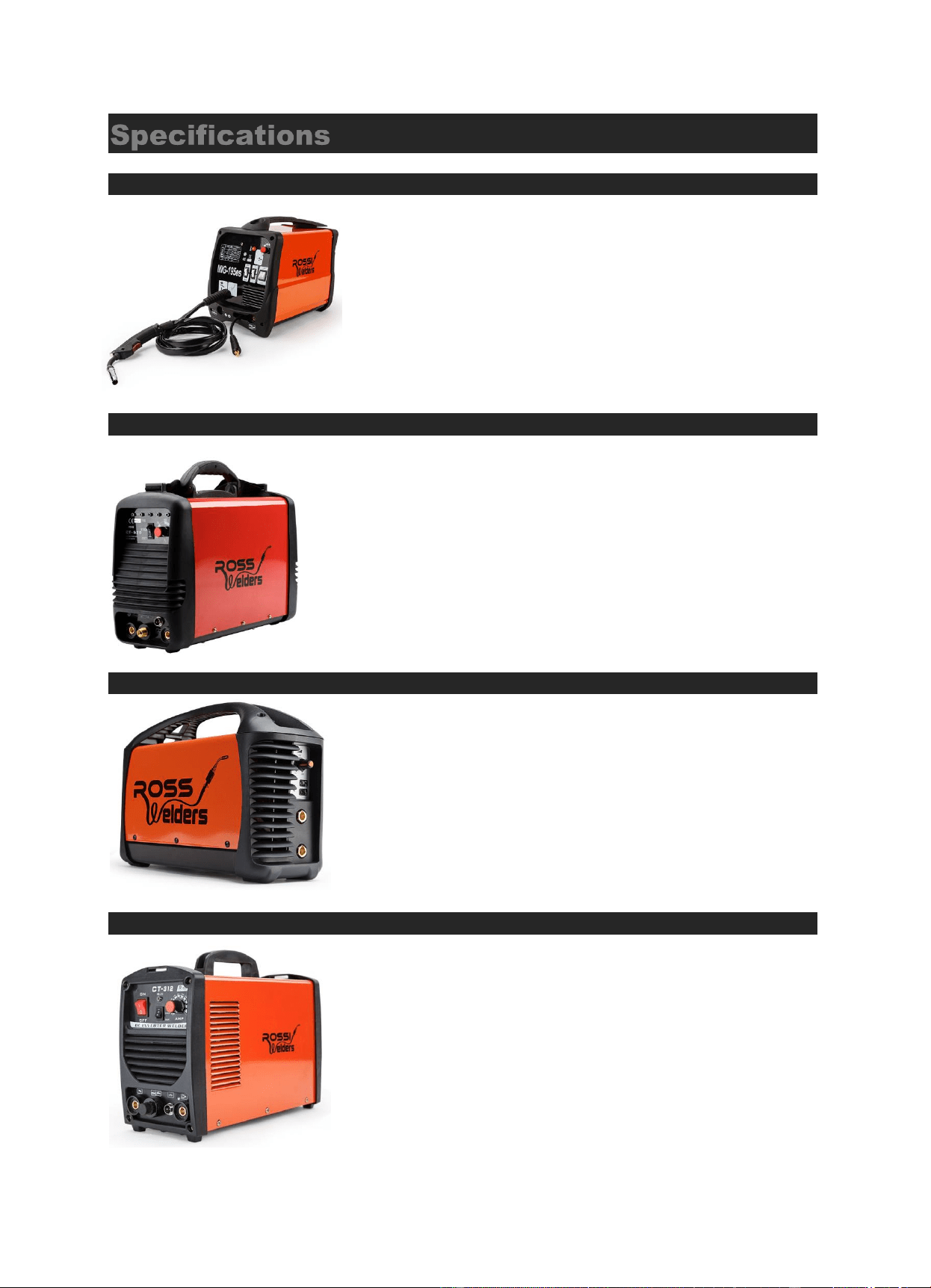
Product Manual – Rossi Welders
110914123000
38
38
Rossi Welders
Specifications
WLDMIG195RSSACAA
Process: MIG / MAG / MMA
Input power: 240V, 50Hz
Rated output (duty cycle): 195A-10%, 74A-60%, 60A-100%
Welding amperage range: 40-195Amps (Max)
No load voltage: 33V
Single pass weld: -
Weldable metals: -
Wire diameter range: -
Max spool size: 5kg
Other Specifications: Refer to brochure or advertisement
CT-520
Process: TIG / MMA / CUT
Input power: 240V, 50Hz
Rated output (duty cycle): -
Welding amperage range: TIG 15-200 Amps / MMA 18V / 15-200 Amps /
CUT 28V / 20-50 Amps /125V
No load voltage: -
Single pass weld: -
Weldable metals: Welds Steel, Stainless, Copper, Iron + more
Wire diameter range: -
Max spool size: -
Other Specifications: Refer to brochure or advertisement
ROSSWELDER
Process: ARC
Input power: 240V, 50Hz (15A plug)
Rated output (duty cycle): 35% @ 200A / 60% @ 160A / 100% @ 120A
Welding amperage range: 5-200 Amps
No load voltage: 72V
Single pass weld: -
Weldable metals: -
Wire diameter range: -
Max spool size: -
Other Specifications: Refer to brochure or advertisement
WELD-CT312
Process: TIG / MMA / CUT
Input power: 240V, 50Hz (15A plug)
Rated output (duty cycle):
Welding amperage range: TIG 10-120 Amps / MMA 20-120 Amps / CUT
20-30 Amps
No load voltage: -
Single pass weld: -
Weldable metals: -
Wire diameter range: -
Max spool size: -
Other Specifications: Refer to brochure or advertisement
Downloaded from www.ManualsFile.com manuals search engine
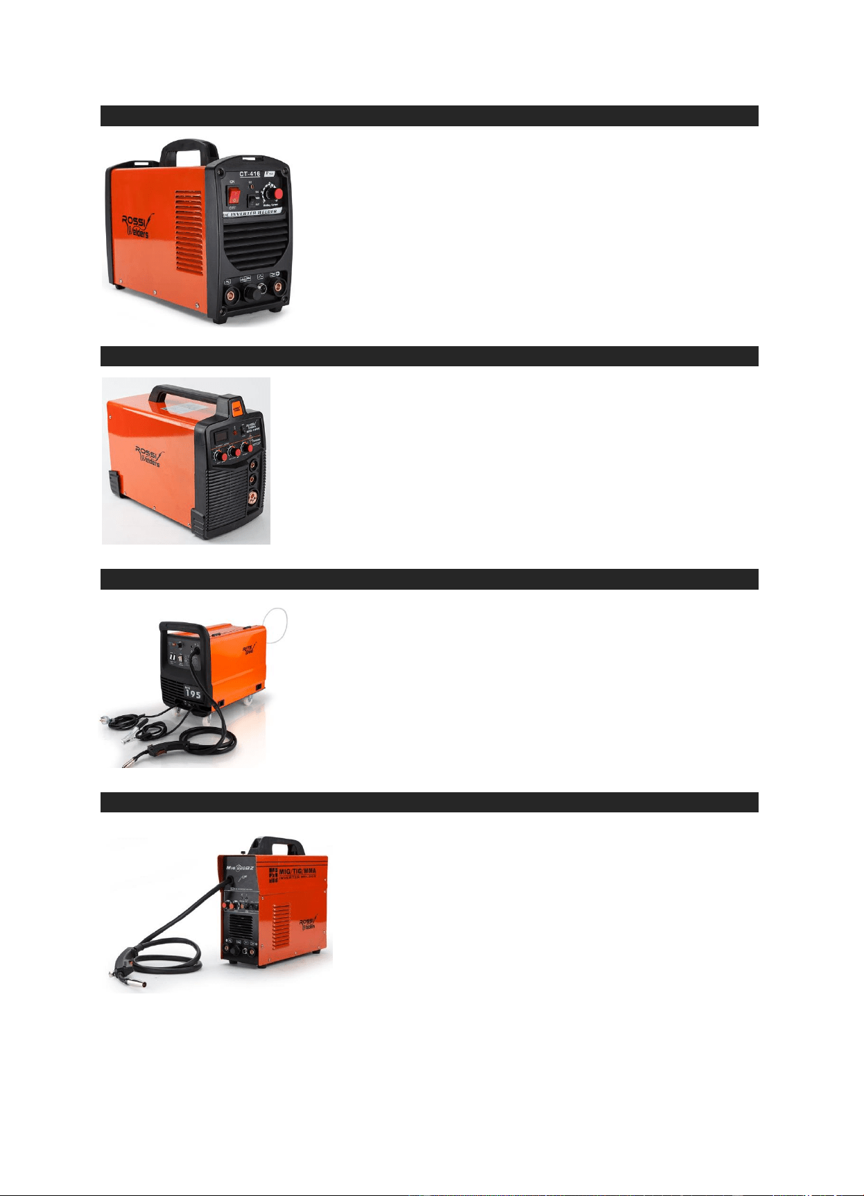
Product Manual – Rossi Welders
110914123000
39
39
Rossi Welders
WELD-CT416
Process: TIG / MMA / CUT
Input power: 240V, 50Hz (15A plug)
Rated output (duty cycle):
Welding amperage range: TIG 10-160 Amps / MMA 20-160 Amps / CUT
20-40 Amps
No load voltage: -
Single pass weld: -
Weldable metals: -
Wire diameter range: -
Max spool size: -
Other Specifications: Refer to brochure or advertisement
WELD-MIG185E
Process: MIG / MAG / MMA
Input power: 220-240V 50Hz (15A Plug)
Rated output (duty cycle): 180A-15%, 90A-60%
Welding amperage range: 60-185Amps (Max)
No load voltage: -
Single pass weld: -
Weldable metals: -
Wire diameter range: 0.8 - 1.0mm, 0.6 - 0.8mm
Max spool size: 5kg
Other Specifications: Refer to brochure or advertisement
WELD-MIG195-ORANGE
Process: MIG / MAG
Input power: 240V, 50Hz
Rated output (duty cycle):
Welding amperage range: 40-200Amps (Max)
No load voltage: 23-38V
Single pass weld: -
Weldable metals: -
Wire diameter range: 0.6mm - 1.0mm
Max spool size: 5kg
Other Specifications: Refer to brochure or advertisement
WELD-MIG220BZ
Process: MIG/MAG/TIG/MMA
Input power: 220-240V 50Hz (15A Plug) +/- 15%
Rated output (duty cycle): -
Welding amperage range: 50-220A
No load voltage: 38
Single pass weld: -
Weldable metals: -
Wire diameter range: 0.8-1.0mm
Max spool size: 2.5kg
Other Specifications: Refer to brochure or advertisement
Downloaded from www.ManualsFile.com manuals search engine
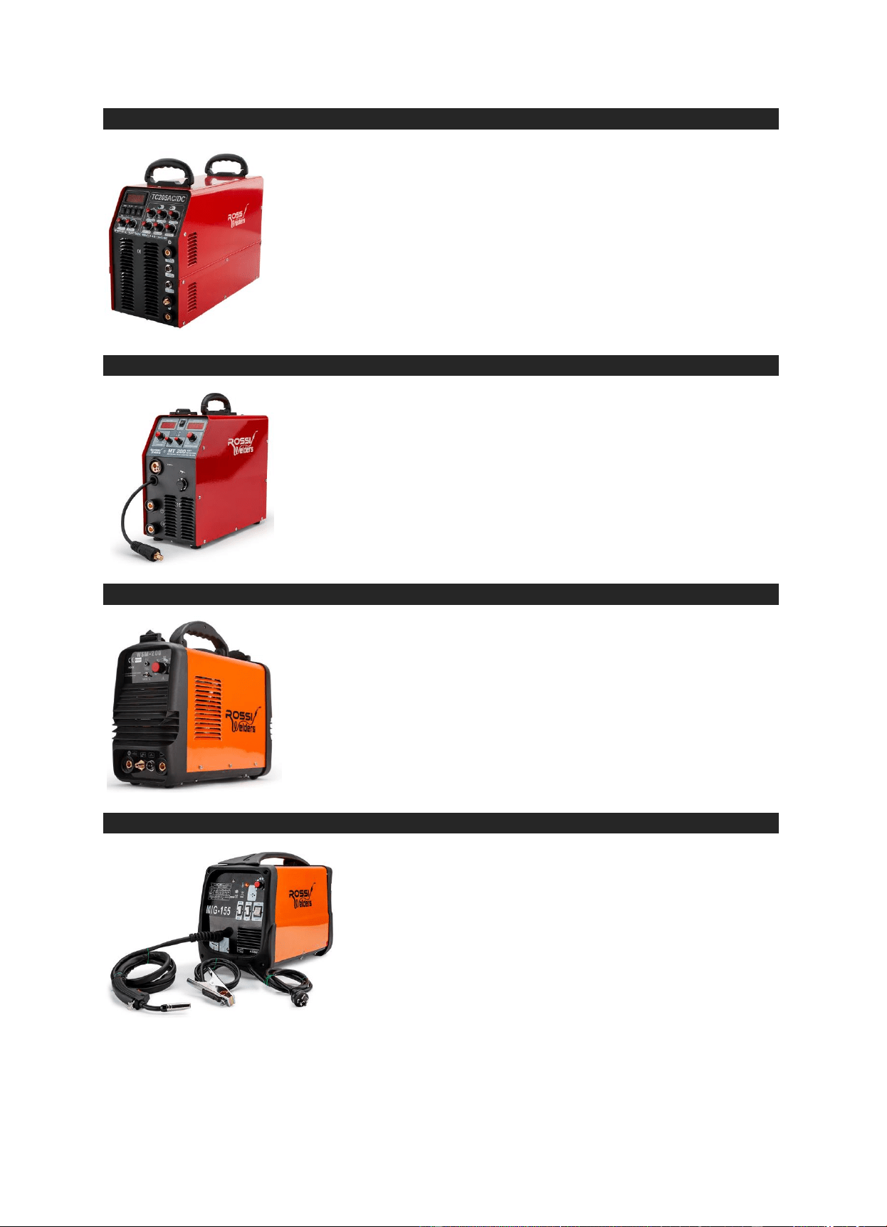
Product Manual – Rossi Welders
110914123000
40
40
Rossi Welders
WELD-ROSSI-205TC
Process: TIG/CUT/MMA
Input power: 240V, 50Hz
Rated output (duty cycle): TIG 60%@200Amps / MMA 35%@160Amps
Welding amperage range: TIG 10-200Amps / MMA 10-160Amps
No load voltage: -
Single pass weld: -
Weldable metals: -
Wire diameter range: -
Max spool size: 5kg
Other Specifications: Refer to brochure or advertisement
WELD-ROSSI-MT200
Process: MIG/TIG/MMA
Input power: 240V, 50Hz (15A)
Rated output (duty cycle):
Welding amperage range: MIG 30-200A
No load voltage: 60
Single pass weld: -
Weldable metals: -
Wire diameter range: -
Max spool size: 1Kg
Other Specifications: Refer to brochure or advertisement
WELD-WSM200
Process: TIG/MMA
Input power: 240V, 50Hz (15A Plug)
Rated output (duty cycle):
Welding amperage range: MMA 5-160Amps / TIG 10-200 Amps @ 18V
No load voltage: -
Single pass weld: -
Weldable metals: -
Wire diameter range: NA
Max spool size: NA
Other Specifications: Refer to brochure or advertisement
WLDMIG155RSSADJE
Process: MIG/MAG
Input power: 240V, 50Hz (15A Plug)
Rated output (duty cycle): 155A-10%, 62A-60%, 50A-100%
Welding amperage range: 30-155Amps (Max)
No load voltage: 23-38V
Single pass weld: -
Weldable metals: -
Wire diameter range: NA
Max spool size: NA
Other Specifications: Refer to brochure or advertisement
Downloaded from www.ManualsFile.com manuals search engine
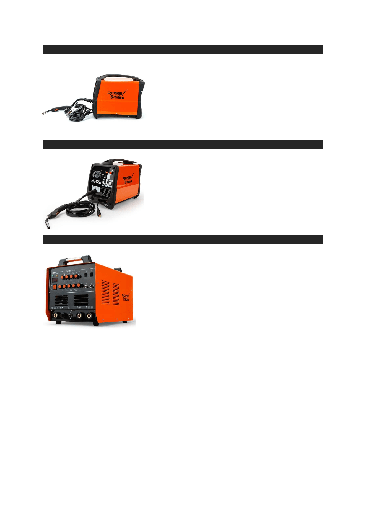
Product Manual – Rossi Welders
110914123000
41
41
Rossi Welders
WLDMIG185RSSADJE
Process: MIG/MAG
Input power: 240V, 50Hz (15A Plug)
Rated output (duty cycle): 185a-10%, 68a-60%, 55a-100%
Welding amperage range: 40-185Amps (Max)
No load voltage: 33V
Single pass weld: -
Weldable metals: -
Wire diameter range: 0.6-0.8mm to 0.8-1.0mm
Max spool size: 5kg
Other Specifications: Refer to brochure or advertisement
WLDMIG195RSSADJE
Process: MIG/ MAG/ MMA
Input power: 240V, 50Hz (15A Plug)
Rated output (duty cycle): 195a-10%, 74a-60%, 60a-100%
Welding amperage range: 40-195Amps (Max)
No load voltage: 33V
Single pass weld: -
Weldable metals: -
Wire diameter range: 0.6-0.8mm to 0.8-1.0mm
Max spool size: 5kg
Other Specifications: Refer to brochure or advertisement
WLDPAA200ROSADJB
Process: AC/DC/TIG
Input power: 240V, 50Hz (15A Plug)
Rated output (duty cycle): TIG 60%@200Amps / MMA
35%@160Amps / Plasma Cutter 60%@50Amps
Welding amperage range: MMA 10-160A / Plasma Cutter 15-50A
No load voltage: -
Single pass weld: -
Weldable metals: -
Wire diameter range: NA
Max spool size: NA
Other Specifications: Refer to brochure or advertisement
Downloaded from www.ManualsFile.com manuals search engine

Product Manual – Rossi Welders
110914123000
42
42
Rossi Welders
Glossary
AC Welders – Aluminium & Magnesium
DC Welders – All other metals
Arc Force – This function enables operators to tailor the shape of the volt/amp curve to better suit the different
joint configurations and electrode types.
DCEP – Reverse Polarity
DCEN – Straight Polarity
AC Balance – Alternating current contains both electrode positive and electrode negative changing rapidly back
and forth. With Old school machines, you get what you get and roughly 50 /50 dcep/dcen…and you don’t always
need all that cleaning action that you get from the dcep but with most TIG inverters, you can adjust the ac
balance to more than 90 % dcen. Rule of thumb: for nasty aluminium like a boat prop that has some corrosion,
adjust the ac balance to where you use more dcep .For brand new clean aluminium diamond plate, set the ac
balance to where you have around 70-80 percent dcen.
AC Frequency – power from the power company is roughly 50-60 Hz in different countries. An inverter steps the
frequency of the incoming AC power up before it even converts it to DC. That’s why the transformer is so small
light compared to older TIG welders the A/C frequency knob allows you to weld with a much higher frequency.
That option stiffens and focuses the TIG welding arc pinpoints the heat.
Basic current / Base current (Amperage) - The amount of electricity flowing past a point in a conductor every
second.
Clean area width (Phase Balance) – Applies to AC welding and sets the proportion of time the weld current is
positive, during which time the current has an "oxide penetrating" effect on the aluminium alloy weld pool surface,
but which also tends to heat up and melt the tungsten electrode rather than the weld pool. Maximum heat is
delivered to the work piece/job when the electrode is negative so this setting is used to achieve the best
compromise when welding ally.
Down-Slope Time – Allows the current to decrease at whatever rate you set on the knob.
Peak current – Peak current is the nominal current for the high energy pulse. It is adjusted to a level that is set
consistently above the globular to spray transition current. Peak current is expressed in units of ampere. During
the time when the peak current is delivered, the molten droplet detaches from the electrode. An increase in peak
current increases the average welding current and the weld penetration.
Pre flow - The length of time the torch gas flows before the arc terminates.
Post Gas – The length of time the torch gas flows after the arc terminates.
Pulse Duty (duty cycle) – The number of minutes out of a 10-minute time period an arc welding machine can be
operated at maximum rated output. An example would be 60% duty cycle at 300 amps. This would mean that at
300 amps the welding machine can be used for 6 minutes and then must be allowed to cool with the fan motor
running for 4 minutes.
Pulse Frequency – The sequencing and controlling of the amount of current, frequency and duration of the
welding arc.
Pulse width (Pule % on time) - The time the high pulse amperage stays on.
Up-Slope Time – Allows the current to climb at whatever rate you set…from start amperage to operating main
amperage setting on the machine
Wire Speed / Speed – The speed at which wire is fed out of the machine.
2T - for using a switch on the torch handle…when you plug in the foot pedal or torch amperage control, most TIG
inverters are designed to bypass the 2t and 4t settings because the amperage control overrides all the upslope
and downslope stuff. The 2t setting pretty much turns the torch switch into a 2 position switch. Press the switch,
you get and arc, let off the switch, arc goes out.
4T - The 4T position is most always used in conjunction with upslope and downslope settings. For example;
a. Press the button and you get an arc.
b. Let off the button and the arc upslope to whatever the main amperage is set to Weld.
c. Press the button and arc downslopes to lower amperage
d. Let off the button and arc quits.
e. Some machines are different but this is the general principle of 4t operation
Start Amps - allows for a really low amperage start-up or a hot one
End Amps - determines the final amperage before the arc quits.
Downloaded from www.ManualsFile.com manuals search engine