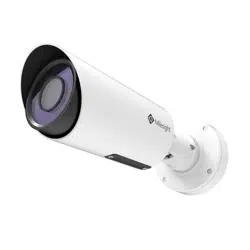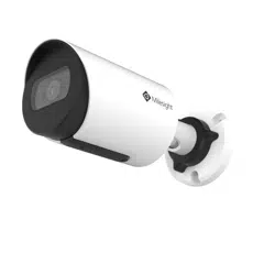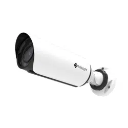
SP111/SP112
QUICK START
GUIDE
Milesight IoT Co., Ltd.
www.milesight.com/security
User Manual
Security ANPR
(Parking)
ANPR
(Road Traffic)
Table of Contents
1. Package Contents.........………………………………………………………………………...................
2. Hardware Overview……………………………………………………………………….............................
3. Dimensions.....................................................……………………………………………………….
4. Installation........................................................………………………………………………………
5. Configuration.....................................................…………………………………………………….
6. FCC Statement......................................................................................................
2
4
6
8
15
17
www.milesight.com/security
Limited Warranty Protection
36 months (for Camera) and 24 months (for Solar-powered Accessories)
from the original purchase date against all manufacturing defects.:
Loss or damage to the equipment due to improper maintenance, or failure to
follow operating instructions.
If defects or damages are caused by the use of unauthorized parts or by
service by other than our authorized agent.
Model:
Date of Purchase:
Serial Number:
MAC Address:
For details, please visit our website:
www.milesight.com/security
Dealer Stamp
12 131 2 13
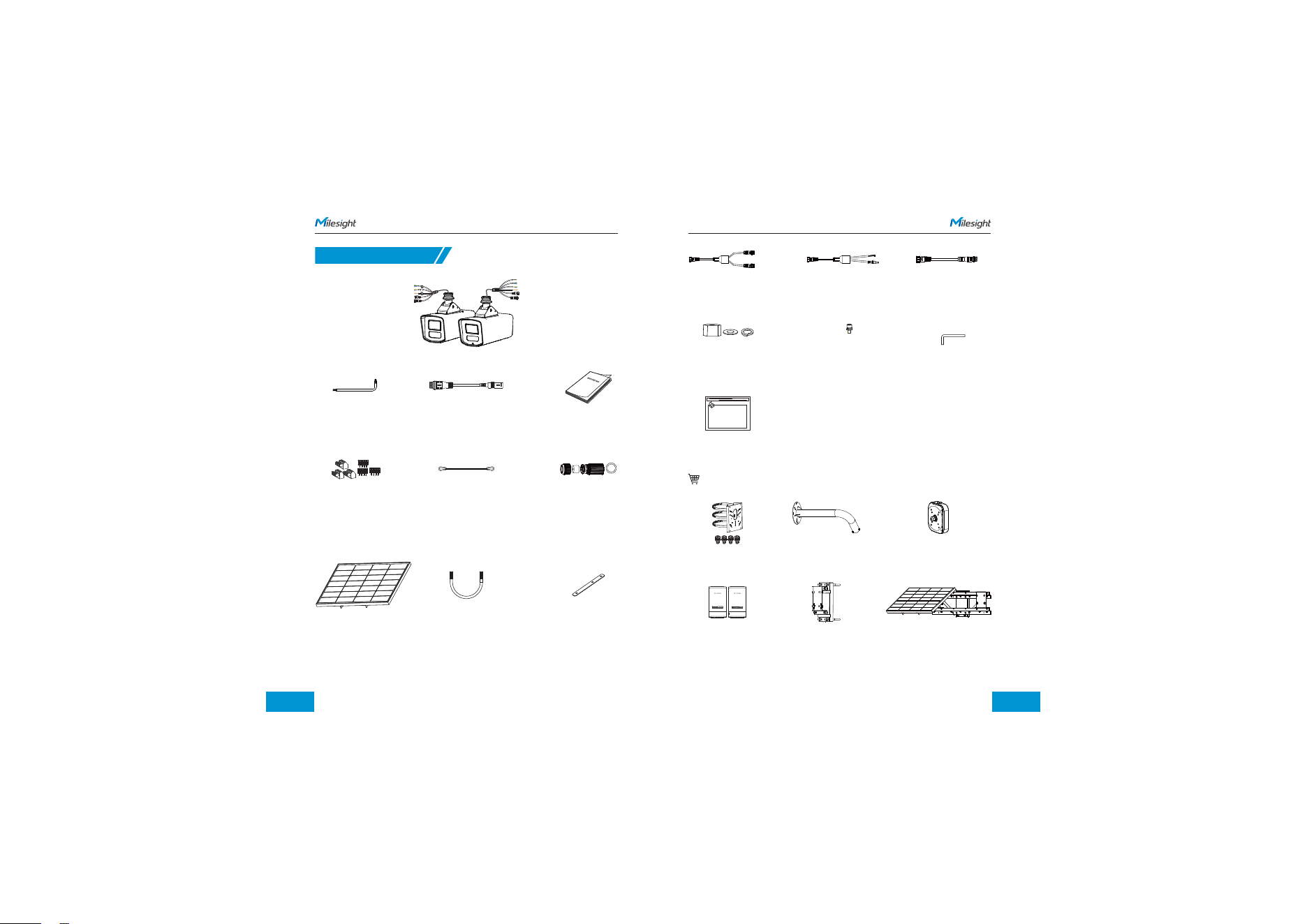
1. Package Contents
Camera Quick
Start Guide x 1
Screwdriver x 1 DC cable x 1
Terminal x 3 Camera Safety
Strap x 1
Waterproof
Connector x 1
Optional
SA02 Bracket A43 Junction BoxA02 V2 Bracket
BJ-N Bracket S100 Expansion ModuleOutdoor Wireless CPE
Solar Panel
Solar Kit
(S100B55/S100B96)
U type
hoop x 2
Bracket
Fasteners x 2
Dual Device
Power Splitter
DC+RS485
Cable
Camera Power
Cable
Nuts × 4
Washers × 4
Spring washers × 4
M6 screws × 6
Hex Wrench x 1
Solar Panel Quick
Start Guide
www.milesight.com/security www.milesight.com/security
4G Solar-powered Camera x 1
1 4 15
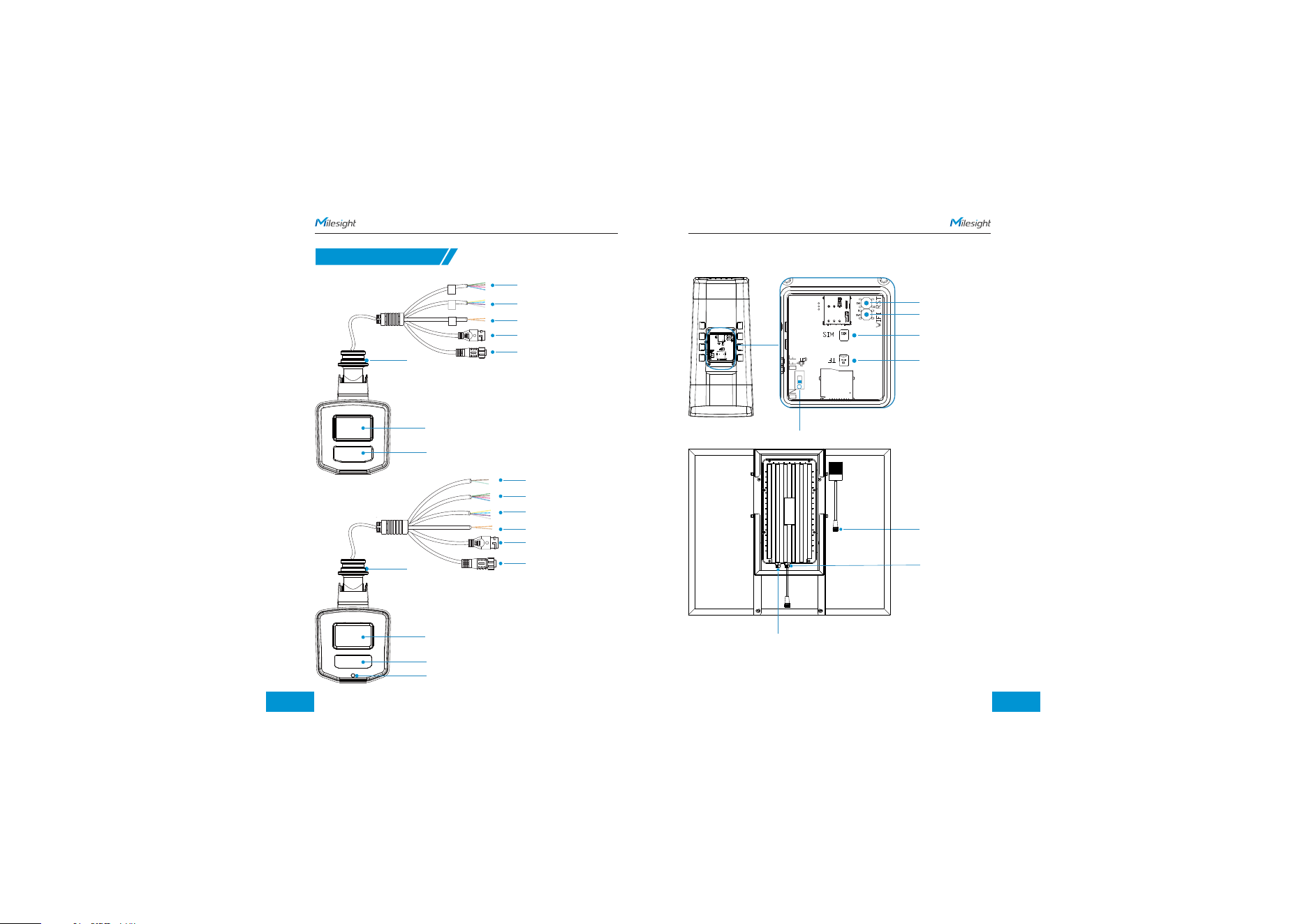
Camera (SP111)
Camera (SP112)
ON/OFF
V1
SW1
SW2
LED
WIFI RST
Reset
WiFi
SIM Card Slot
SD Card Slot
V1
U31
SW1
SW2
J1
EN
NET2
NET1
R27
micro
SD
SIM
ON OFF
LED
TF
WIFI RST
SIM
micro
SD
SIM
TF
SIM
2. Hardware Overview
Solar Panel Output
Power Supply (M14-5)
Solar Power Input
www.milesight.com/security www.milesight.com/security
Mounting
Interface
Audio In *1 & Audio Out *1
Green & Brown & Pink & Sky Blue
Alarm In *1 & Alarm Out *1
Yellow & Pure Blue & Purple & White
RS485
Orange & Orange/White
Ethernet Port
Power Supply (M14-5)
(used for power supply and RS485
battery information communication
with the battery system)
Lens
IR LEDS
Mounting
Interface
Audio In *1 & Audio Out *1
Green & Brown & Pink & Sky Blue
Wie gand Data 0/1
Cyan & Sepia
Alarm In *1 & Alarm Out *1
Yellow & Pure Blue & Purple & White
RS485
Orange & Orange/White
Power Supply (M14-5)
(used for power supply and RS485
battery information communication
with the battery system)
Ethernet Port
Lens
IR LEDS
Light Sensor
1 6 17
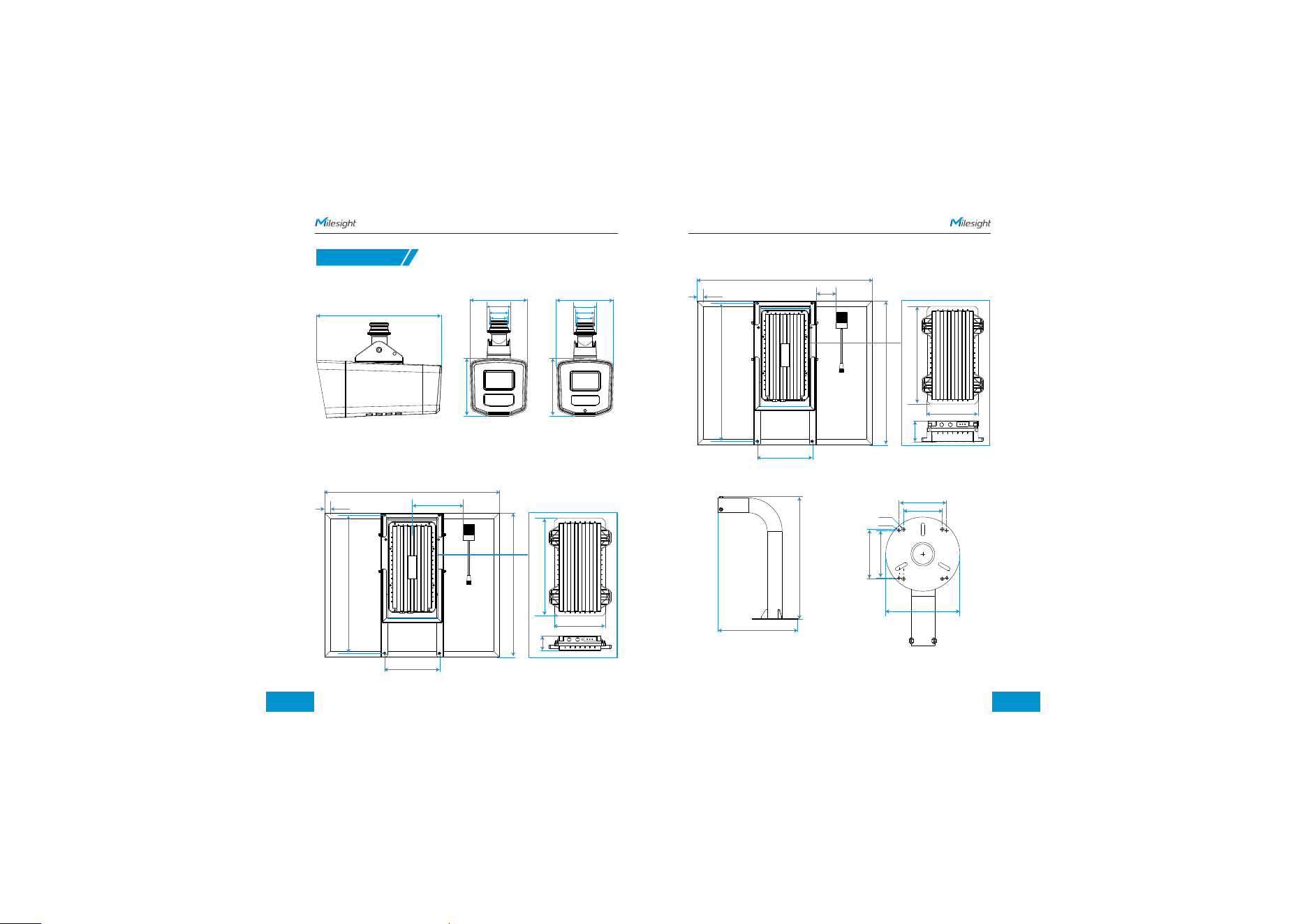
3.Dimensions
1. Camera
SP111 / SP112 SP111
260
120
120
120
39
48
34
120
39
48
34
SA02
Units: mm
4*ƶ7
96
78.5
400
260
150
100
96
4*ƶ5
S100B55
765
25
150
230
597
207
630
397
60
S100B96
765
25
150
230
597
207
630
397
84
www.milesight.com/security www.milesight.com/security
SP112
1 8 9
4. Installation
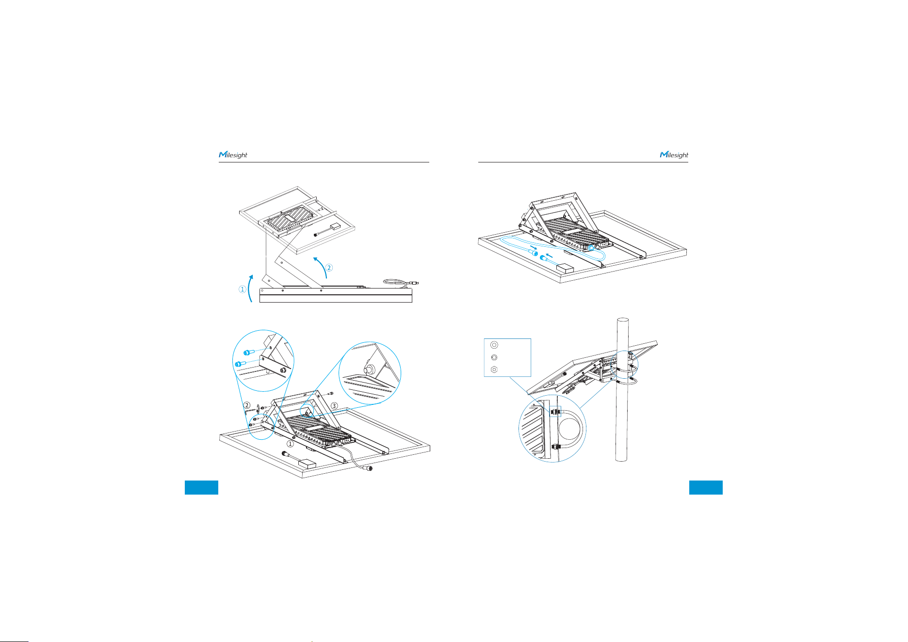
Step 2: Place the solar panel kit horizontally
www.milesight.com/security www.milesight.com/security
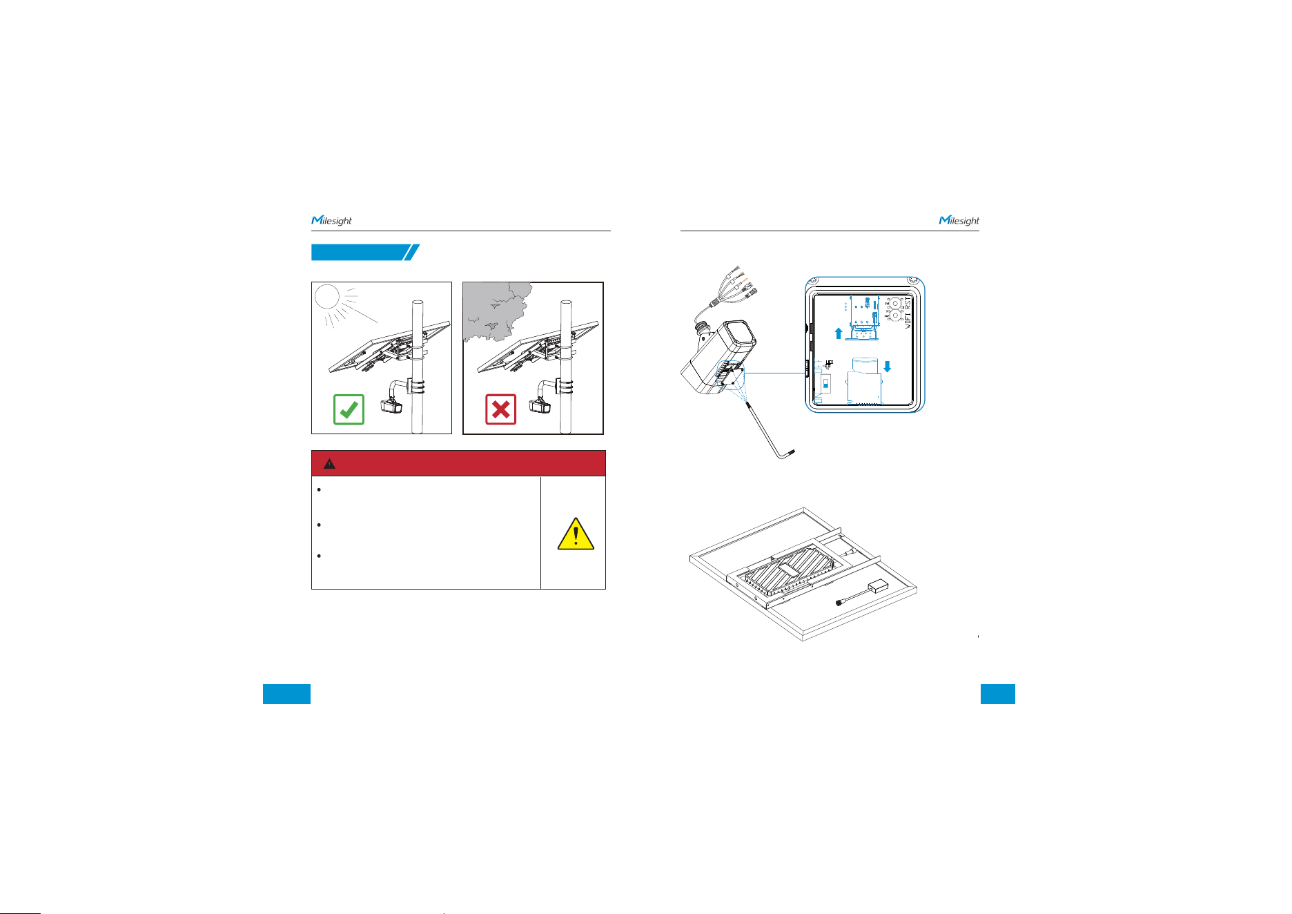
Step 1: Use a screwdriver to open the back cover at the bottom of the camera. Insert the
SD card and SIM card.
V1
SW1
SW2
LED
WIFI RST
CAUTION
The best installation direction for solar panels is due southin
the northern hemisphere and due north in the
southernhemisphere.A compass must be used for positioning
Solar panels should be installed in an openunobstructedplace
directly facing towards the sun for better pawer efficiency.
Lithium-ion battery should be put through at least one
charge-discharge cycle every 3 to 6 months to ensure
properoperation.
110 111
Step 3: Lift the two brackets
Step 4: Fasten the brackets on both sides. Make sure the screw holes on the top
plate line up with the bracket's inner holes.
www.milesight.com/security www.milesight.com/security
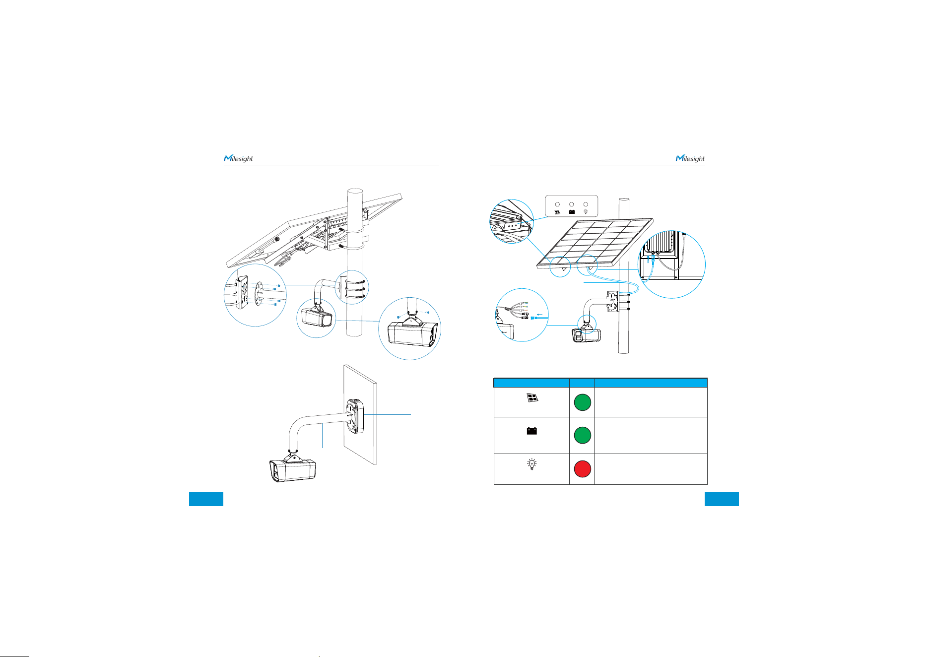
Step 5: Connect the Solar Panel Output to the Solar Power Input on the battery.
Step 6: Secure the equipment onto a vertical pole (diameter 80mm–114mm) using
U-type hoops and the provided fastener sets
(including nuts, washers, and spring washers).
Spring Plate
Nuts
Washer
112 113
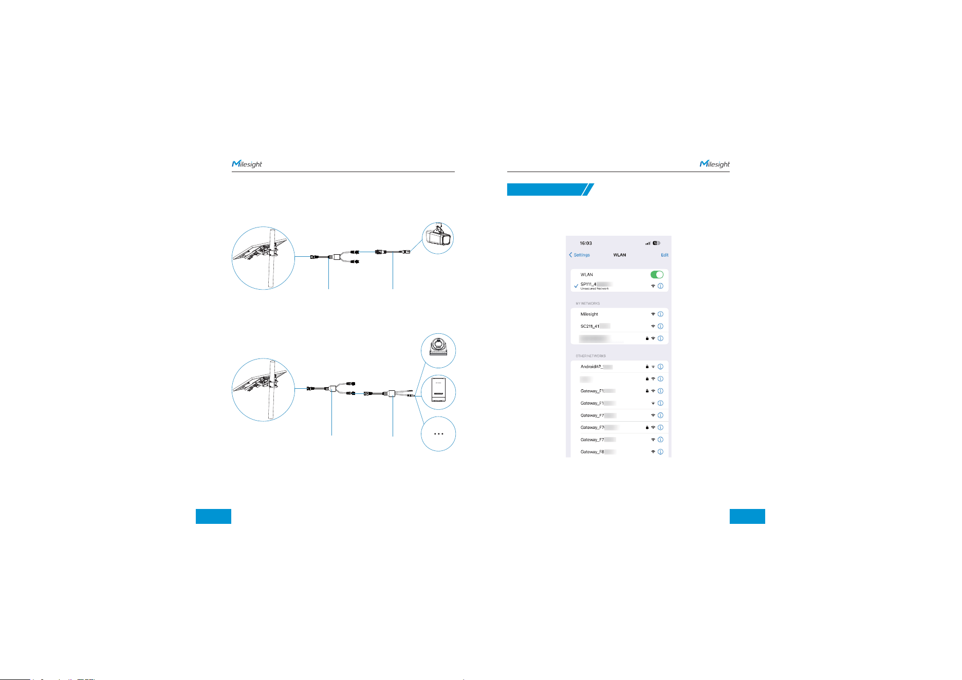
ON: Solar energy is charging the battery
OFF: Solar energy did not charge the battery
Flashing: Battery capacity exceeds 95% and
the battery is fully charged
ON: Battery voltage is normal
Slow Flashing: Battery voltage is insufficient
and it flickersonce every 4 seconds
Quick Flashing: Battery low voltage
protection flashes onceevery 1 second
ON: There is voltage output at the output
terminal
OFF: There is no voltage output at
the output terminal
Solar panel indicator
Battery indicator
Load indicator
Colour
Indicator
Status
www.milesight.com/security www.milesight.com/security
Pole Installation
A02 V2
SA02
Wall Installation
Indicator Light Status:
SA02 Bracket
A43
Green
Green
Red
Step8 : Connect the power output interface of the solar panel to the Camera Power
Cable, and then connect the other end of the cable to the camera. After installing
and securing the camera, check the status of the indicator lights.
Camera Power Cable
114 115
Cable Connection
1.Dual Device Power Splitter
A 1-to-2 power cable. Used to simultaneously power two devices (e.g., a network bridge
and a camera) from a single solar output.
Dual Device Power Splitter
2. Bridge Data & Power Cable
Supports various DC-powered devices (cameras, network bridges, etc.). Features RS485
data transmission for solar system status monitoring.
DC+RS485 Cable
CPE
www.milesight.com/security www.milesight.com/security
5. Configuration
Step 1: Press the camera's WiFi button to turn on the WiFi.
Step 2: Step 2: Use mobile devices or laptop to connect to the device's Wi-Fi.
The Wi-Fi name is SP111_xxxxxx/ SP112_xxxxxx (xxxxxx is the last six bits of the
MAC address).
Note:
When the device is powered on, the indicator light will slowly flash green until
XLIHIZMGIMWJYPP]FSSXIHEX[LMGLTSMRXMX[MPPVIQEMRWSPMHKVIIRɸ8LI;M*MSJ
device is automatically enabled when the device is powered on.
Camera Power Cable
Dual Device Power Splitter
Camera
117
6. FCC Statement
FCC Radiation Exposure Statement:
Any changes or modifications not expressly approved by the party responsible
for compliance could void the user’s authority to operate the equipment.
This device complies with part 15 of the FCC Rules. Operation is subject to the
following two conditions:
1. This device may not cause harmful interference.
2. This device must accept any interference received, including interference that
may cause undesired operation.
This equipment complies with FCC radiation exposure limits set forth for an
uncontrolled environment. This equipment should be installed and operated
with minimum distance 20cm between the radiator& your body. This transmitter
must not be co-located or operating in conjunction with any other antenna or
transmitter.
Note: This equipment has been tested and found to comply with the limits for a
Class B digital device, pursuant to part 15 of the FCC Rules. These limits are
designed to provide reasonable protection against harmful interference in a
residential installation. This equipment generates, uses and can radiate radio
frequency energy and, if not installed and used in accordance with the
instructions, may cause harmful interference to radio communications. However,
there is no guarantee that interference will not occur in a particular installation.
If this equipment does cause harmful interference to radio or television reception,
which can be determined by turning the equipment off and on, the user is
encouraged to try to correct the interference by one or more of the following
measures:
1.Reorient or relocate the receiving antenna.
2.Increase the separation between the equipment and receiver.
3.Connect the equipment into an outlet on a circuit different from that to which
the receiver is connected.
4.Consult the dealer or an experienced radio/TV technician for help.
116
www.milesight.com/security www.milesight.com/security
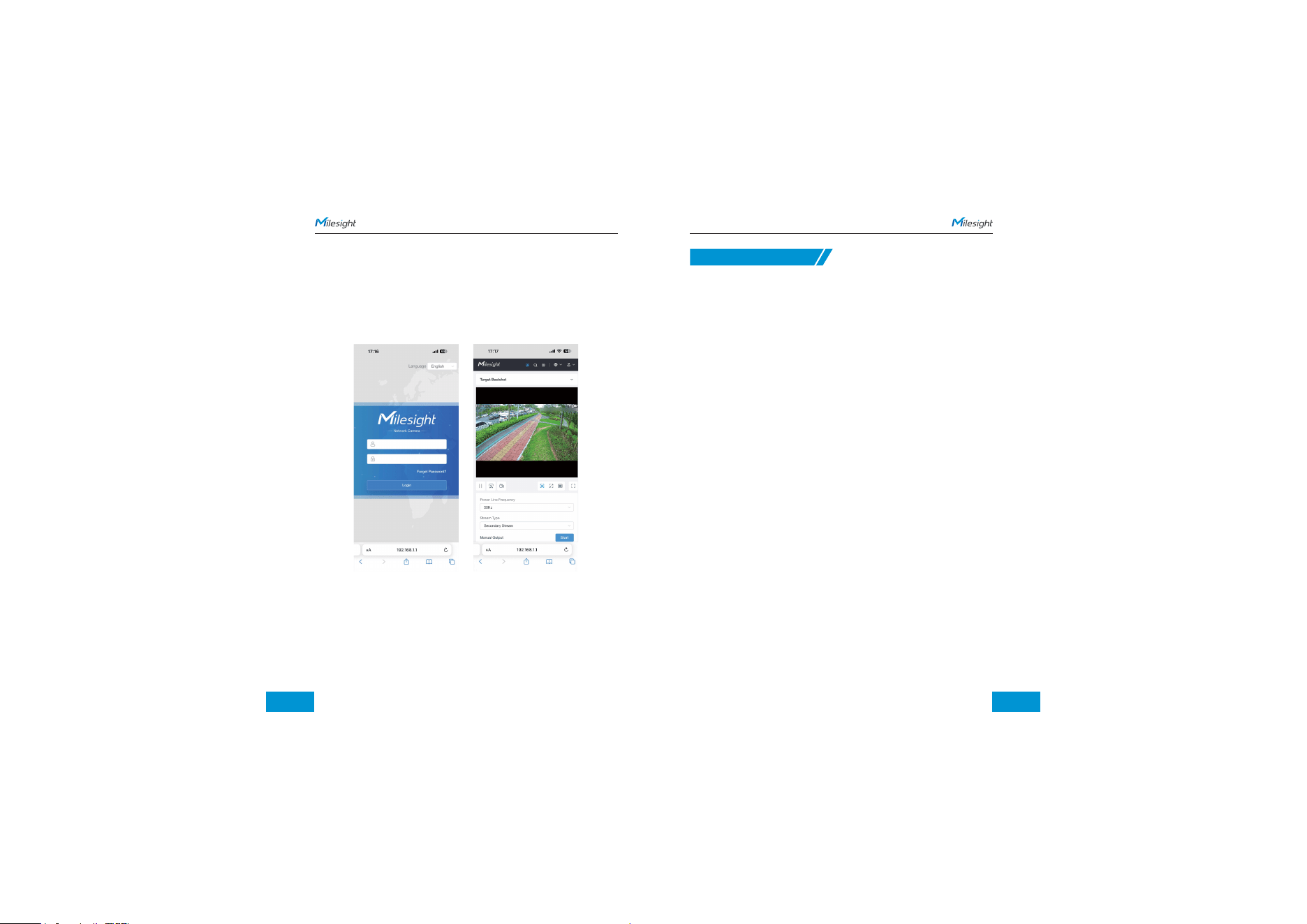
Step 3: Enter the IP address 192.168.1.1 in the browser to log in to the web
page of the device and configure the device.
Note:
1. First-time login requires activating the camera and setting a password.
2. The IP address of the device cannot be modified.
3. For more information about how to configure the device, please refer to the
User Manual.
Step 4: After completing the device configuration, lock the camera cover to
ensure data security.
Note:
Press and hold the reset button (for about 5 seconds) until the green light
flashes quickly five times. At this point, the device has been reset, and you
can release the button.