-1-
Instructions for the installation, use and care of:
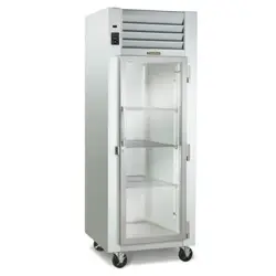
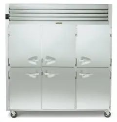
R-Series / G-Series
TE-Series / TU-Series / TS-Series
Quick Start Guide
Receipt & Support Installation
You should carefully inspect your Traulsen unit for damage during delivery. If damage is detected, you should
save all the crating materials and make note on the carrier’s Bill Of Lading describing the damage. A freight
claim should be led within 5 days.
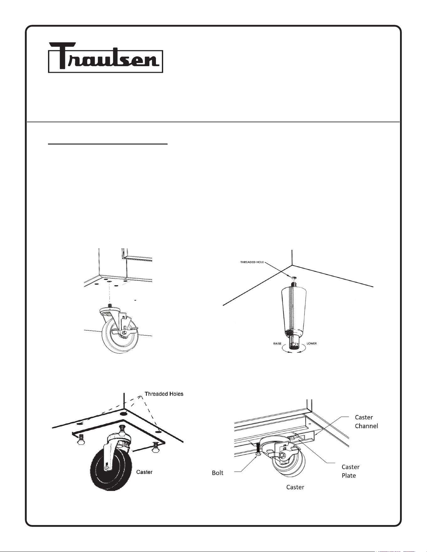
After uncrating the unit, select a level location for nal placement. Install the casters (or optional leg supports)
as shown below.
Supports: “Plate “ casters (Standard for G ), “Stem” type legs (Standard for R), “Channel” type casters
(Standard for TE,TU,TS)
Stem Type Leg
Plate Type Caster Channel Caster
Stem Type Caster
-2-
Traulsen models may use R-290 (Propane) as a refrigerant. If ammable refrigerant is present, follow instructions
as labeled on the unit. Proper care must be taken to avoid any damage to refrigeration system including refrigerant
tubing, condenser, evaporator coils during handling, moving, installation and cleaning as it may cause risk of re
or explosion. If damaged, unit must be moved to well ventilated area away from any sources of ignition.
Further service and repair must be performed by qualied refrigeration technicians familiar with applicable safety
standards for ammable refrigerants. Technicians must use appropriate personal protective equipment and follow
applicable safety precautions to avoid risk of re or explosion.
Upright models should be installed to allow at least 12” of clear space above the unit. In all cases, the louvers must be free
of any obstruction which could prevent proper airow.
Most units are supplied with a cord and plug, which can simply be plugged into a dedicated appropriately sized outlet. For
those requiring hard-wiring directly to the power supply, this should be done by a qualied electrician only.
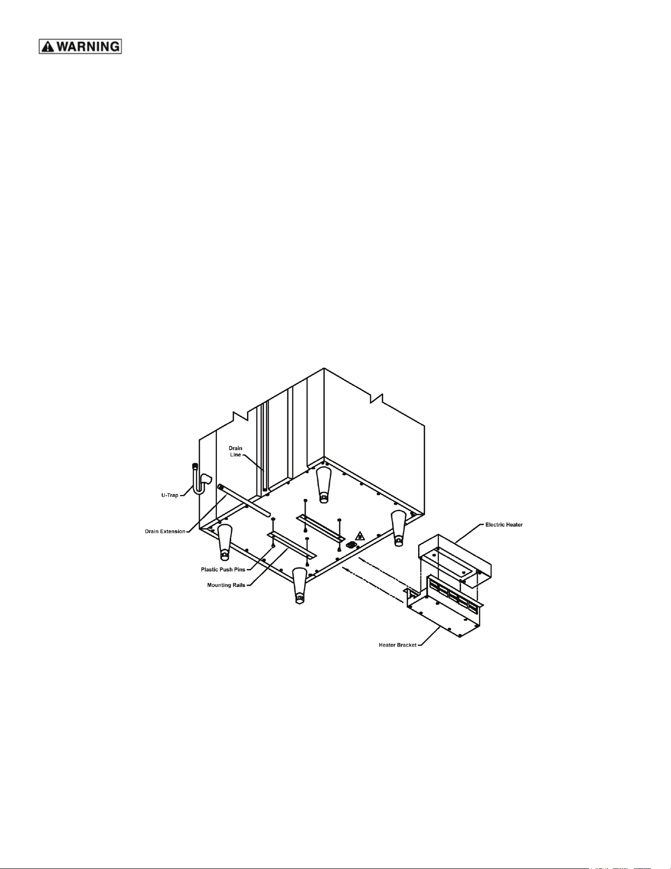
NOTE: Some models require provision of a bottom mounted condensate evaporator. Follow instructions provided with part,
along with the gure below for installation.
Bottom Mounted Condensate Evaporator
-3-
Uprights Control Overview
Most Traulsen equipment is plug and play. However, once power is supplied to the unit, you may make minor adjustments
to your Traulsen unit.
NOTE: Can be horizontal or vertical.
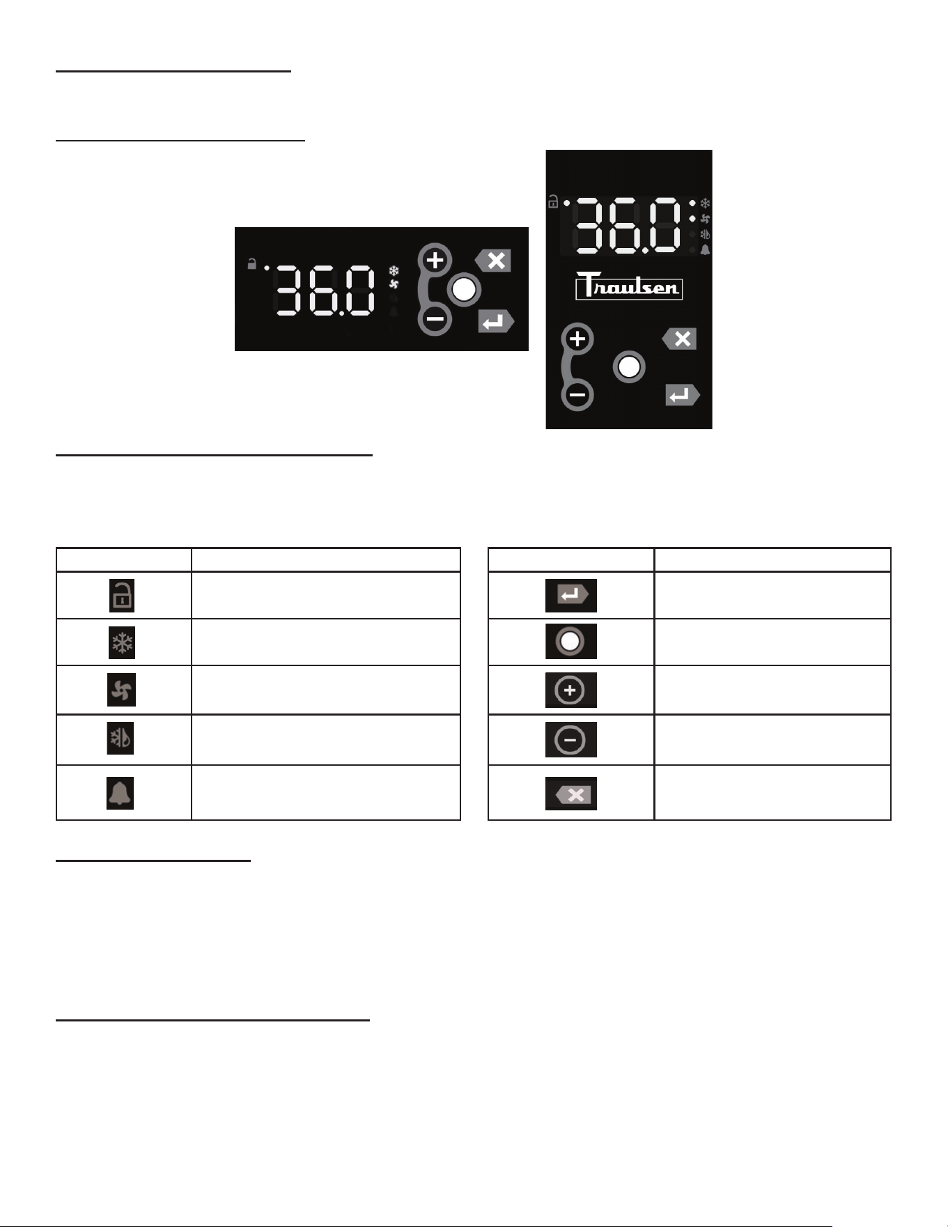
Understanding the Uprights Display
On the left or top portion of the display there are colored LEDs for showing the temperature, compressor status, fans,
whether the control is locked/unlocked, etc.
On the right or bottom portion of the display there are ve tactile buttons that manage the operation of the unit.
Unlocking the Keypad
Normally, the keypad is locked to prevent inadvertent changes to settings. The unlock key is a white dot on the right or
bottom portion of the display, centered between the other four buttons. Press the unlock key twice within a second in order
to unlock the keypad (think “tap-tap”). The unlock LED will illuminate to indicate the keypad is live. They keypad will stay
unlocked until three minutes of inactivity have passed, at which time it will automatically lock the keypad. There are two
operations the user can perform without having to enter a password: change the temperature setpoint, initiate a defrost
operation, or turn the heaters o if unit is a hot food cabinet.
Changing the Temperature Setpoint
The setpoint to the unit can be changed simply by pressing the Plus (+) or Minus (-) key. There will be a slight delay at
rst to prevent an accidental change, so it will be necessary to hold the key for three-four seconds until the value starts to
ash. The ashing value indicates the setpoint is being modied. To raise the setpoint, press the Plus (+) key to increment
to the setpoint you want. SImilarly, press the Minus (-) key to lower the setpoint. When the desired value is reached, pres
the Enter / Display “↵” key to lock in the value. Pressing the Escape /Back / Cancel key “X” will abort the process and
keep the original setpoint. The keypad must be unlocked in order to change the setpoint using the shortcut method.
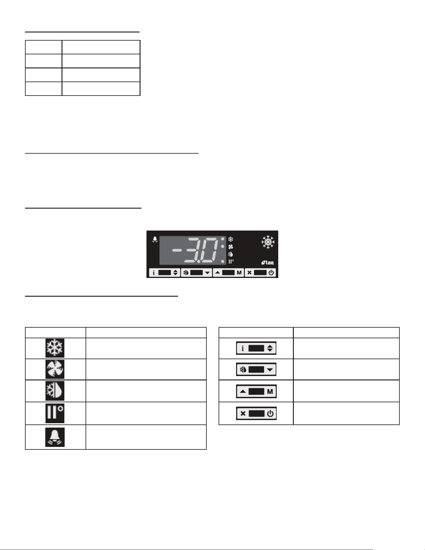
LED SYMBOL DESCRIPTION
Unlock
Compressor / Heater Status
Fan Status
Defrost Status
Alarm / Door Open
BUTTON SYMBOL DESCRIPTION
Display / Enter
Unlock / Modify
Plus (+) / Next
Minus (-) / Previous
Escape / Back / Cancel
-4-
Initiating a Defrost Operation
Defrost is a necessary operation to remove frost that builds up on the evaporator
coil and reduces airow within the cabinet. Normally this is done automatically
based on a time interval and the ambient conditions of the environment. A special
sensor is used to measure the humidity in the air to adjust the defrost interval
depedning upon humidity levels. The nominal defrost intervals are shown in the
table on the left.
To manually defrost the unit, press the Minus (-) key and the Escape /Back / Cancel key “X” simultaneously and hold for
five seconds. Units equipped with and LED temperature display will indicate when a drefrost cycle is in progress. The
defrost LED will illuminate to indicate that a defrost operation is in progress. Depending on the settings, the display may
show “dEF”.
Turning the Heaters O - Hot Food Cabinets
The keypad must be unlocked in order to deactivate the heaters. Press the unlock key twice within a second in order to
unlock the keypad (think “tap-tap”). The unlock LED will illuminate to indicate the keypad is live. To turn the unit o, press
and hold the unlock key until the display shows “OFF”. To turn the unit on, press the unlock key until the display shows the
cabinet temperature.
Horizontals Control Overview
Most Traulsen equipment is plug and play. However, once power is supplied to the unit, you may make minor adjustments
to your Traulsen unit.
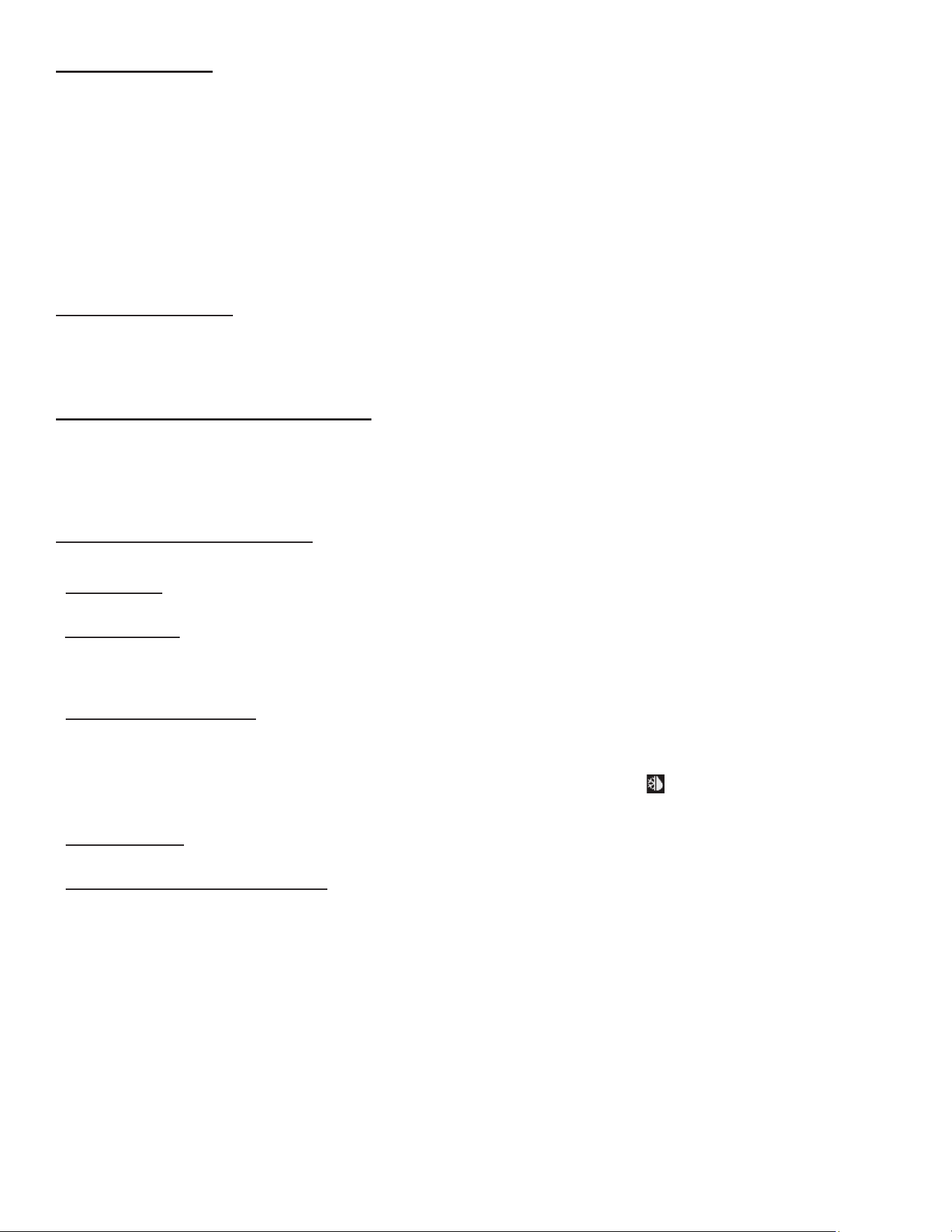
Understanding the Horizontals Display
To the left and right of the display screen there are colored LEDs for showing the temperature, fans, defrost, etc.
On bottom portion of the display there are four push buttons that manage the operation of the unit.
UNIT DEFROST INTERVAL
Upright Ref 8 hours
Upright Frz 4 hours
Horizontals 6 hours
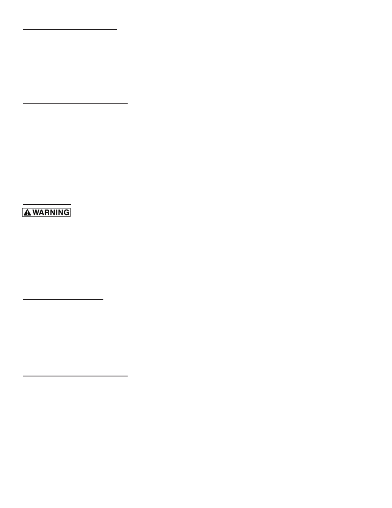
LED SYMBOL DESCRIPTION
Thermostat Output
Fan Status
Defrost Status
Activation of 2
nd
Parameter Set
Alarm
BUTTON SYMBOL DESCRIPTION
Parameter Menu
Defrost Operation / Decrease
Manual Activation / Increase
Exit / Stand By
-5-
Information Menu
The information available in this menu is: Instant Probe 1 Temperature “t1”, Instant Probe 2 Temperature “t2”* and
Compressor Working Weeks “cnd”**.
*Displayed only if enabled (see Conguration Parameters in the following sections)
**Displayed only if ACC > 0
To access the menu and information press and immediately release the Parameter Menu “i” button. Navigate to the data
you want to display with the Manual Activation / Increase “▲” or Defrost Operation / Decrease “▼” button. Press the
Parameter Menu “i” button to display the value. To exit the menu, press the Exit / Stand By “X” button.
To initiate a stand by, press and hold the Exit / Standy By “⏻” button for three seconds. This allows the control to be put
on stand by or the output control to be resumed (with SB = YES only).
Locking the Keypad
The ability to lock the keypad helps to avoid undesired, potentially dangerous, operation which might be attempted when
the controller is operating in a public place. In the Information Menu, set parameter LOC = YES to inhibit all functions of
the buttons. To resume normal operation of the keypad, adjust the parameter to LOC = NO.
Changing the Temperature Setpoint
To modify the temperature setpoint, Press the Parameter Menu “i” button for at least half a second to display the setpoint
value. While keeping the Parameter Menu “i” button pressed, use the Manual Activation / Increase “▲” or Defrost
Operation / Decrease “▼” buttonto set the desired value (adjustment is within the minimum SPL and the maximum SPH
limit). When the Parameter Menu “i” buttonis released, the new value is stored.
Initiating a Defrost Operation
Defrost starts automatically as soon as the time set with parameter DFT has elapsed.
• Timed Defrost: With DFM = TIM defrost takes place at regular intervals when the timer reaches the value of DFT. For
example, with the factory set DFM = TIM and DFT = 36, a defrost operation will take place every six hours.
• Adaptive Defrost: With DFM = FRO the timer is only increased when the conditions occur for frost to form on the
evaporator, until the time set with parameter DFT is matched. If the evaporator works at 0°F, defrost frequency depends
on the thermal load and ambient conditions. With setpoints lower than 0°F defrost frequency mainly depends on the unit
operating time.
• Defrost Time Count Backup: When operation resumes, if DFB = YES, the defrost timer resumes the time count from
where it was left off before the operation disruption. When DFB = NO, the time count re-starts from zero. In stand by, the
accumulated time count is frozen.
It’s possible to manually start a defrost by pressing the Defrost Operation / Decrease “ ” button for two seconds.Once
the defrost operation has started, the compressor and defrost outputs are controlled according to parameter DTY. If FID =
YES, the evaporator fans are active during defrost. The actual defrost duration is influenced by a series of parameters.
• Time Termination: T2 = NO and T3 different from 2EU; the evaporator temperature is not monitored and defrost will last
as long as time DTO.
• Temperature Monitoring of Evaporator: T2 = YES and T3 different from 2EU; the sensor T2 measures the temperature
DLI before the time DTO elapses. Defrost will be terminated in advance.
When the defrost opereation ends, the thermostatic cycle resumes if DRN is greater than zero. All outputs will remain off
for DRN minutes, in order for the ice on the evaporator coil to melt completely and the resulting water to drain. Moreover,
if probe T2 = YES, the fans will re-start when the evaporator gets to a temperature lower than FDD. Vice versa, if probe
T2 = NO or after the defrost operation has come to an end, such condition does not occur by the end of the time FTO,
after FTO minutes have elapsed the fans will be switched on anyway. CAUTION: If DFM = NON or C-H = HEA all defrost
functions are inhibited; if DFT = 0, automatic defrost operations are excluded.
-6-
Conguration Parameters
To get access to the parameter conguration menu, press and hold the Exit / Standy By “⏻” and the Parameter Menu
“i” buttons simultaneously for five seconds. Press the Manual Activation / Increase “▲” or Defrost Operation / Decrease
“▼” button to select the parameter to be modified. Press the Parameter Menu “i” button to display the value. Then press
and hold the Parameter Menu “i” button while simultaneously pressing the Manual Activation / Increase “▲” or Defrost
Operation / Decrease “▼” button to set the desired value. When the Parameter Menu “i” button is released, the newly
programmed value is stored and the following parameter is displayed. To exit the parameter configuration menu, pres the
Exit / Stand By “X” button or wait thirty seconds.
Operation Display Indicators
During normal operation, the display shows either the temperature measured or one of the following indications:
• dEF = Defrost in progress
• oFF = Controller in stand by
• cL = Condenser clean warning
• do = Door open alarm
• E1 = Probe T1 failure
• E2 = Probe T2 failure
• E3 = Probe T3 failure
General Care
Disconnect the electrical power supply before cleaning any part of the unit. All Traulsen equipment should be
cleaned only with warm water, mild soap and a soft cloth. Apply with a dampened cloth and wipe in the direction of the
metal grain.
Avoid the use of strong detergents and gritty, abrasive cleaners as they may tend to mar and scratch the surface. Do NOT
use cleansers containing chlorine- this may promote metal corrosion.
Care should be taken to avoid splashing the unit with water, containing chlorinated cleansers, when mopping the oor
around the unit. For stubborn odor spills, use baking soda and water (mix 1 tablespoon baking soda : 1 pint water ratio).
Adjusting the Shelves
Shelves Mounted on Pins: First select the desired location and remove the white plastic covers in the interior back and
sides by rotating them counterclockwise. Remove the shelf pins by rotating them counterclockwise. Install the pins in the
desired location by rotating clockwise. Make sure the pin is securely tightened. Do not over tighten. Slide the shelf into its
new position and replace the white plastic covers into the holes vacated by the shelf pins.
Shelves Mounted on Pilasters and Clips: For each shelf, insert four shelf clips into the pilaster slots at the same height.
The shelf clips have a small projection on top which holds the shelf in position and prevents it from slipping forward. After
installing shelf clips on pilasters, place shelves on the clips.
Operation Display Indicators
Disconnect the electrical power supply before cleaning any part of the unit. This is the single most important thing
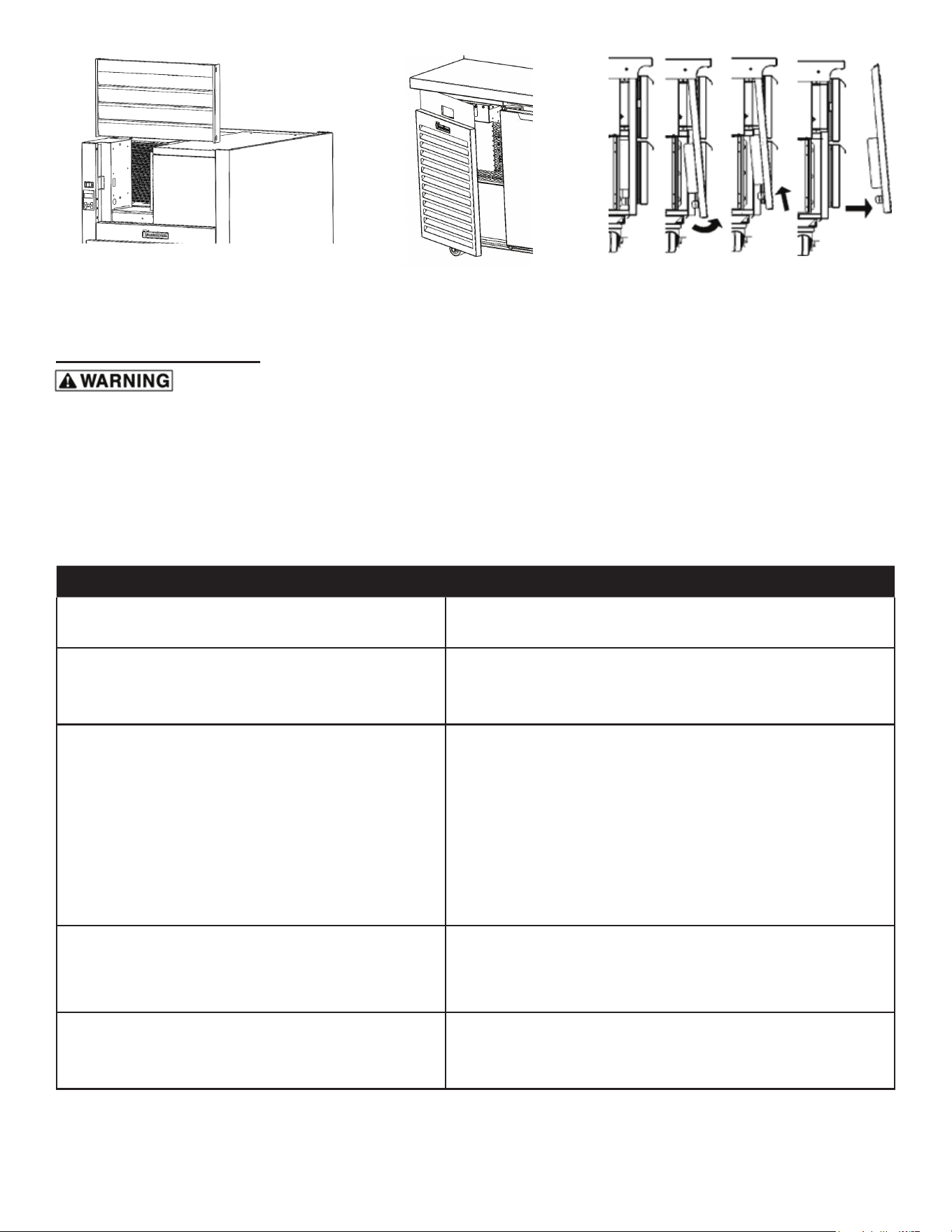
you can do to promote long, ecient equipment life. For all upright cabinets, remove the two bottom screws that secure
the louver panel, then pivot this upward to allow full access to the front-facing condenser. For all horizontal cabinets, you
will either gently pull to swing open (like a door) or gently lift up and out the louver panel o bracket of the unit (see next
page).
Vacuum or brush any dirt, lint or dust from the condenser coil, around the compressor and other cooling system
components as indicated. If signicant dirt is clogging the condenser ns, use compressed air to blow this clear. When
nished reverse the louver removal process as instructed above.
-7-
Troubleshooting Guide
Some models may use R-290 (Propane) as a refrigerant. Service and repair must be performed by qualied
refrigeration technicians familiar with applicable safety standards for ammable refrigerants. Technicians must
use appropriate personal protective equipment and follow applicable safely precautions to avoid risk of re or
explosion. Service and repair must be performed in well ventilated and unconned area, away from any ignition
sources. All system components must be replaced with like components. Factory recommends to use exact
make and models to assure the consistent performance and to minimize the risk of possible ignition due to
incorrect parts. In case of uncertainty or parts unavailability, contact Traulsen technical assistance at 800-825-
8220.
PROBLEM REMEDY
1. Condensing unit fails to start.
a. Has the cord and plug has been disconnected? Reconnect.
b. Check control temperature setting.
2. Condensing unit operates for prolonged periods or
continuously.
a. Are doors open? Shut completely.
b. Is the condenser coil clean? Clean properly.
c. Is the evaporator coil frozen? Initiate defrost.
3. Food compartment is too warm.
a. Check doors and gaskets for proper alignment and seal.
b. Has a large quantity of warm food recently been added,
or was the door kept open for a long period of time? In both
cases allow adequate time for the cabinet to recover its normal
operating temperature.
c. Is the setpoint too high? Readjust setpoint.
d. Is the condenser coil clean? Clean properly.
e. Is product properly loaded into the unit? Be sure to allow
proper airow.
4. Food compartment is too cold.
a. Has a large quantity of very cold or frozen food recently
been added? Allow adequate time for the cabinet to recover its
normal operating temperature.
b. Is the setpoint too low? Readjust the setpoint.
5. Condensation on the exterior surface.
a. Check doors and gaskets for proper alignment and seal.
b. Depending on amount, condensation could be normal if unit
is in a high-humidity environment.
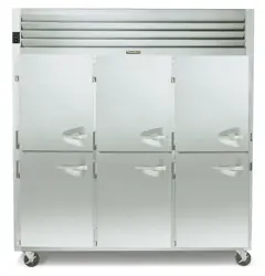
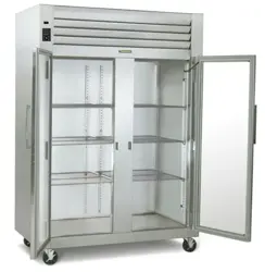
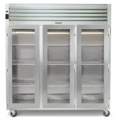
R-Series & G-Series Cabinets TE-Series & TU-Series CabinetsTS-Series Cabinets
-8-
Service & Warranty Information
Before calling for service, please check the following:
Is the electrical cord plugged in? NOTE: If the SUPPLY CORD is damaged, it must be replaced by the manufacturer,
its service agent, or similarly qualied persons in order to avoid a possible electrical hazard.
Is the fuse OK or circuit breaker on?
Is the condenser coil clean?
Is the power switch on?
If after checking the above items and the unit is still not operating properly, please contact an authorized Traulsen service agent:
4401 Blue Mound Road Fort Worth, TX 76106 | (800) 825-8220. Traulsen reserves the right to change specications or
discontinue models without notice.
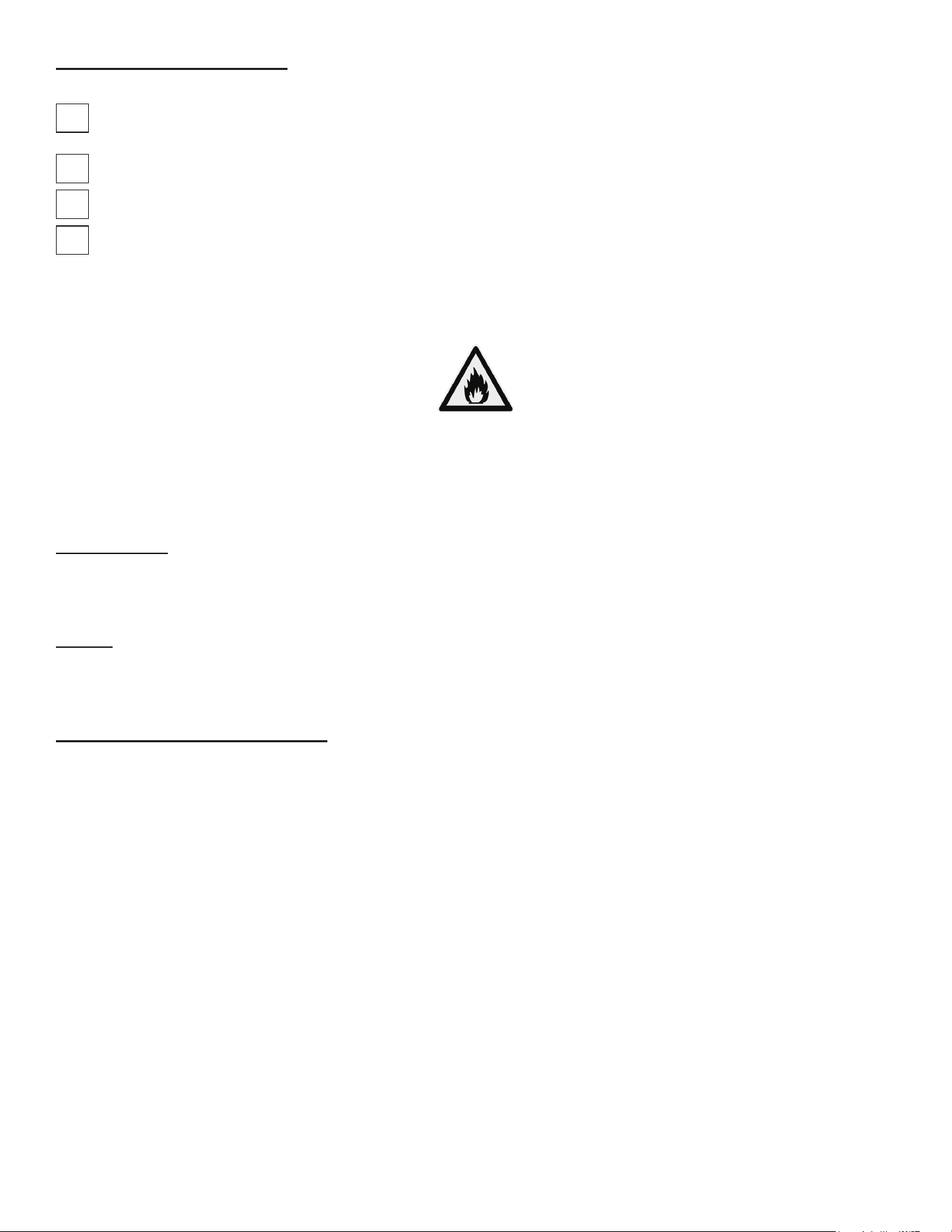
NOTE: The ISO 7010-W021 symbol is a standardized safety sign used internationally to indicate a potential re hazard.
It features a black ame icon on a triangular yellow background with a black border, following ISO guidelines for warning
symbols. This appliance is marked with the ISO 7010-W021 warning label to indicate the presence of FLAMMABLE
REFRIGERANTS. Prior to beginning work on systems containing FLAMMABLE REFRIGERANTS, safety checks are
necessary to ensure that the risk of ignition is minimized.
Ventilated Area
Ensure that the area is in the open or that it is adequately ventilated before breaking into the system or conducting any
hot work. A degree of ventilation shall continue during the period that the work is carried out. The ventilation should safely
disperse any released refrigerant and preferably expel it externally into the atmosphere.
Cabling
Check that cabling will not be subject to wear, corrosion, excessive pressure, vibration, sharp edges, or any other adverse
environmental eects. The check shall also take into account the eects of aging or continual vibration from sources such
as compressors or fans.
Detection of Flammable Refrigerants
Under no circumstances shall potential sources of ignition be used in the searching for or detection of refrigerant leaks. A
halide torch (or any other detector using a naked ame) shall not be used.
The following leak detection methods are deemed acceptable for all refrigerant systems. Electronic leak detectors may
be used to detect refrigerant leaks but, in the case of FLAMMABLE REFRIGERANTS, the sensitivity might not be
adequate, or might need recalibration. (Detection equipment shall be calibrated in a refrigerant-free area.) Ensure that
the detector is not a potential source of ignition and is suitable for the refrigerant used. Leak detection equipment shall be
set at a percentage of the LFL of the refrigerant and shall be calibrated to the refrigerant employed, and the appropriate
percentage of gas (25 % maximum) is conrmed.
Leak detection uids are also suitable for use with most refrigerants but the use of detergents containing chlorine shall be
avoided as the chlorine can react with the refrigerant and corrode the copper pipe-work.
NOTE: Examples of leak detection uids are
• bubble method
• uorescent method agents
If a leak is suspected, all naked ames shall be removed/extinguished.
If a leakage of refrigerant is found which requires brazing, all of the refrigerant shall be recovered from the system, or iso-
lated (by means of shut o valves) in a part of the system remote from the leak. Removal of refrigerant shall be according
to the removal & evacuation section below.
-9-
Removal & Evacuation
When breaking into the refrigerant circuit to make repairs- or for any other purpose - conventional procedures shall
be used. However, for ammable refrigerants it is important that best practice be followed, since ammability is a
consideration. The following procedure shall be adhered to:
a) safely remove refrigerant following local and national regulations;
b) purge the circuit with inert gas;
c) evacuate
d) purge with inert gas;
e) open the circuit by cutting or brazing.
The refrigerant charge shall be recovered into the correct recovery cylinders if venting is not allowed by local and national
codes. For appliances containing ammable refrigerants, the system shall be purged with oxygen- free nitrogen to render
the appliance safe for ammable refrigerants. This process might need to be repeated
several times. Compressed air or oxygen shall not be used for purging refrigerant systems .
For appliances containing ammable refrigerants, refrigerants purging shall be achieved by breaking the vacuum in the
system with oxygen-free nitrogen and continuing to ll until the working pressure is achieved, then venting to atmosphere,
and nally pulling down to a vacuum. This process shall be repeated until no refrigerant is within the system (optional for
A2L). When the nal oxygen-free nitrogen charge is used, the system shall be vented down to atmospheric pressure to
enable work to take place.
Ensure that the outlet for the vacuum pump is not close to any potential ignition sources and that ventilation is available.
Spare Parts Information
To purchase replacement parts or to speak to service support for Traulsen units please contact our Ft. Worth facility by phone
at 800-825-8220 or fax to 817-740-6748 (parts) or 817-740-6757 (service).
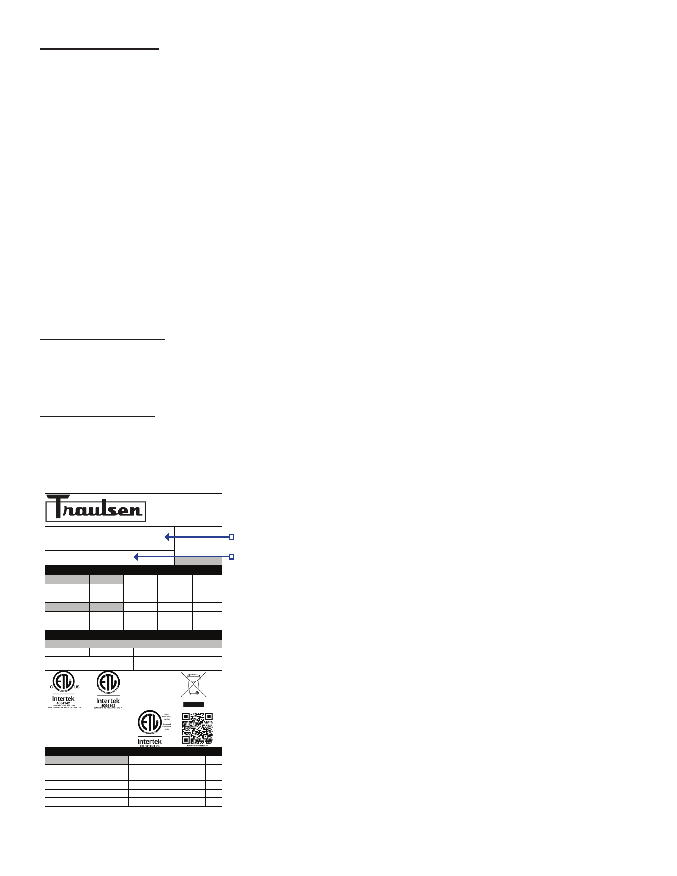
NOTE: When calling for spare parts or service support, please make sure you have model and serial number of unit available.
Warranty Registration
The warranties for your new Traulsen unit may be registered with us by completing warranty information online, via our
website www.Traulsen.com. Click on the Warranty Registration text of the Service tab at the top of the home page. You
may also register your product by calling us directly at 800-825-8220.
Please visit our website www.traulsen.com for additional
literature or service/parts information. From our home page,
select your product under the PRODUCTS tab or any of the
following options under the SERVICE & PARTS tab:
• Warranty & Local Service
• Owner’s Manuals
• Parts Pricing
• Service Manuals
• Warranty Registration
Model Number
Serial Number
ITW Food Equipment Group, LLC
North American Refrigeration
4401 Blue Mound Rd.
Ft. Worth, TX 76106
800-825-8220
MODEL:
MODELO:
MODELE:
RDT232WUT-FHS
SERIAL NUMBER:
25F02060
SCAN FOR SERVICE INFO
REFRIGERANT / REFRIGERANTE / RÉFRIGÉRANT
SYS1 (REFM):
R-290
3.80 OZ
107.71 g
107,71 g
Hi Press. (PRESH):
360.00 psi
2,482.11 kPa
2.482,11 kPa
Lo Press. (PRESL):
130.00 psi
896.32 kPa
896,32 kPa
SYS2 (REFA):
R-290
3.00 OZ
85.04 g
85,04 g
Hi Press. (PRESH):
460.00 psi
3,171.59 kPa
3.171,59 kPa
Lo Press. (PRESL):
140.00 psi
965.27 kPa
965,27 kPa
Input Power (ELIN) - FOR INDOOR USE ONLY
Voltage
Hertz
Phase
Total Amps
115 ~
60
1
12.60
Device/Part Number:
RD232W-291
Device/Part Notes:
COMPONENTS / COMPOSANTS / COMPONENTES
1
2
MAX OVER CURRENT PROTECTION (A):
COMP AMPS:
MIN CIRCUIT IN AMPS:
COND FAN AMPS:
DOME LIGHT WATTS:
11
EVAP FAN AMPS:
DISPLAY LIGHT WATTS:
CONTROL AMPS:
DOOR HEATER WATTS:
DEF HEATER WATTS:
B/TMCE HTR WATTS:
370-60297-00 REV. D 01/15/2024

HOURS OF OPERATION:
Monday thru Friday 7:30 AM - 6:30 PM CST
Traulsen
4401 Blue Mound Road Fort Worth, TX 76106
Phone (800) 825-8220
Service Fax (817) 740 6757
www.traulsen.com
TR36392 P/N 375-60378-00 (04/2026)