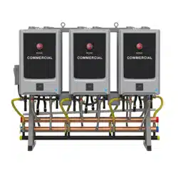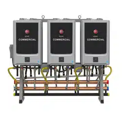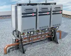
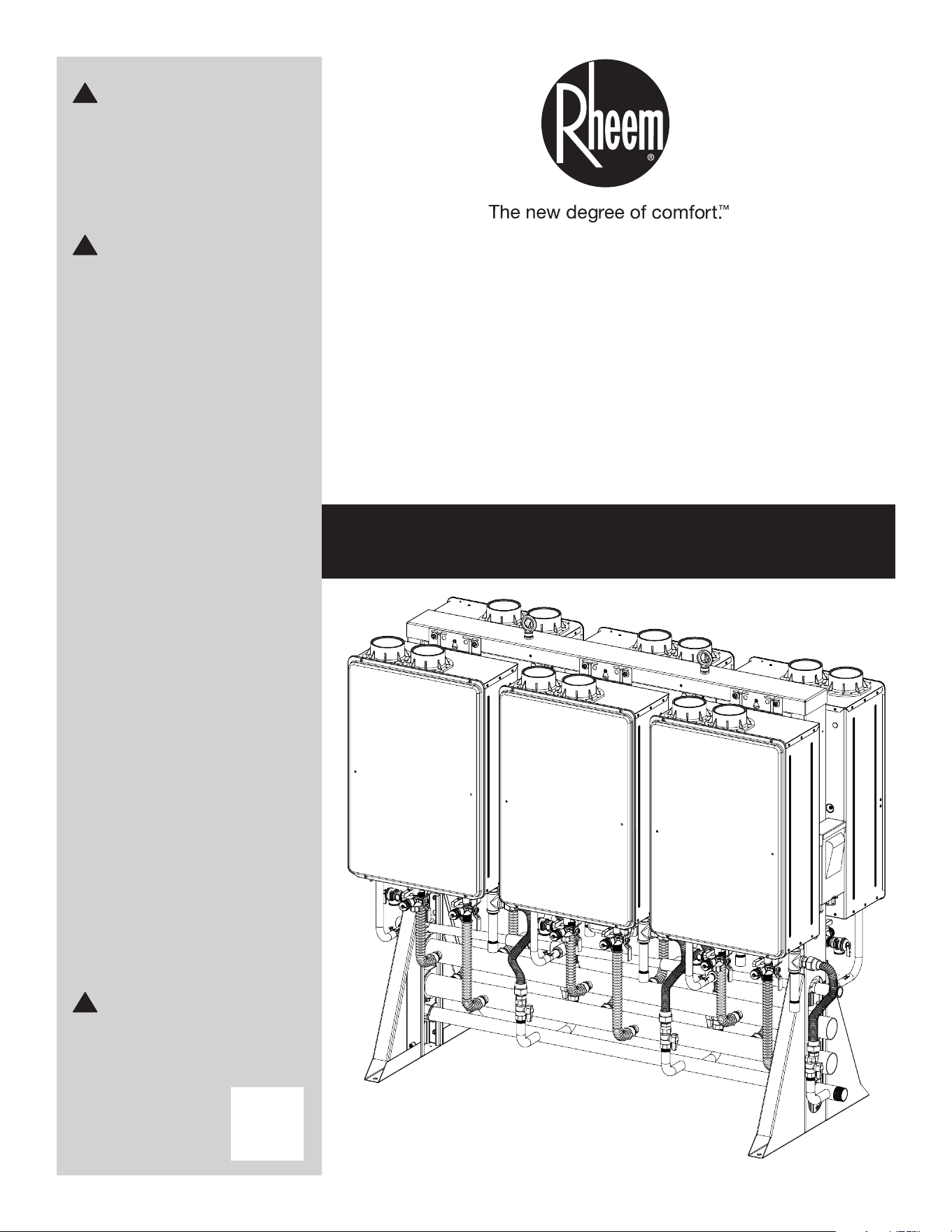
Commercial
Tankless
System (CTS)
AP19266-2 (4/18)
Do not destroy manual. Please
read carefully and keep in a
safe place for future reference.
!
WARNING:
If the information in these
instructions is not followed
exactly, a fire or explosion may
result, causing death, personal
injury, or property damage.
!
WARNING:
This water heater is
not suitable for use in
manufactured (mobile) homes.
!
FOR YOUR
SAFETY!
• Do not store or use gasoline
or other flammable vapours
and liquids in the vicinity of
this or any other appliance.
To do so may result in an
explosion or fire.
• Installation and service must
be performed by a qualified
installer, service agency, or
the gas supplier.
WHAT TO DO IF
YOU SMELL GAS
• Do not try to light any
appliance.
• Do not touch any electrical
switch; do not use any
phone in your building.
• Immediately call your gas
supplier from a neighbor’s
phone. Follow the gas
supplier’s instructions.
• If you cannot reach your
gas supplier, call the fire
department.
• Do not return to your home
until authorized by the gas
supplier or fire department.
Installation Manual

2
CONTENTS
IMPORTANT SAFETY INFORMATION
Your safety and the safety of others are very important.
There are many important safety messages in this
manual and on your appliance. Always read and obey
all safety messages.
This is the safety alert symbol. Recognize
this symbol as an indication of Important
Safety Information! This symbol alerts you to
potential hazards that can kill or hurt you and
others.
All safety messages will follow the safety alert sym-
bol and either the word “DANGER,” “WARNING,”
“CAUTION,” or “NOTICE.”
These words mean:
!
WARNINGS:
• This water heater is not suitable for use in manufac-
tured (mobile) homes!
• Improper installation, adjustment, alteration, service,
or maintenance can cause death, personal injury,
or property damage. Follow the instructions in this
manual.
Read All Instructions
Before Using
Be sure to read and understand the entire Use and Care
Manual before attempting to install or operate this water
heater. It may save you time and money. Pay particular
attention to the Safety Instructions. Failure to follow these
warnings could result in death or serious bodily injury.
Should you have problems understanding the instructions
in this manual, or have any questions, STOP and get help
from a qualified service technician or the local gas utility.
!
DANGER:
NOTICE:
!
CAUTION:
!
WARNING:
!
2...........IMPORTANT SAFETY INFORMATION
9...........DESCRIPTION
10.........RTR PART NOS. AND MAIN COMPONENTS
12.........SPECIFICATIONS
24.........CLEARANCES
25.........HOISTING (LIFTING LUGS)
26.........SECURING THE RACKS
29.........VENTING OPTIONS
PLUMBING
30 .RELIEF VALVE PIPING
30 .PIPING FOR MULTIPLE RACKS
31 .PARALLEL PIPING DRAWING
32 .END CAPS / CONNECTIONS
33 .CONSENSATE DRAIN
33 .CONDENSATE MANIFOLD
34 .CHECKLIST FOR PLUMBING
GAS SUPPLY
34 .INSTALLATION OF GAS SUPPLY
ELECTRICAL
35 .ELECTRICAL CONNECTIONS
36 . ELECTRICAL INDOOR (PRE-WIRED
ELECTRICAL ASSEMBLY)
38 . ELECTRICAL OUTDOOR (PRE-WIRED
ELECTRICAL ASSEMBLY)
40 .MULTIPLE UNITS SETUP
41.........FINAL CHECKLIST
42.........REPLACEMENT PARTS
45.........IF YOU NEED SERVICE
47.........LIMITED WARRANTY
An imminently hazardous
situation that will result in
death or serious injury.
A potentially hazardous
situation that can result in
death or serious injury and/or
damage to property.
A potentially hazardous
situation that may result in
minor or moderate injury.
Attention is called to observe a
specified procedure or maintain
a specific condition.
3
IMPORTANT SAFETY INFORMATION
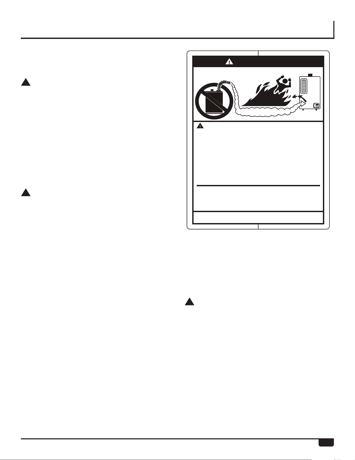
DANGER
FLAMMABLES
Flammable Vapors
Water heater has a main
burner flame.
The main burner flame:
1. which can come on
at any time and
2. will ignite flammable
vapors.
Vapors:
1. cannot be seen,
2. are heavier than air,
3. go a long way on the
floor and
4. can be carried from
other rooms to the
main burner flame by
air currents.
Vapors from flammable
liquids will explode and
catch fire causing death or
severe burns.
Do not use or store flammable
products such as gasoline,
solvents or adhesives in the
same room or area near the
water heater.
Keep flammable products:
1. far away from heater,
2. in approved containers,
3. tightly closed and
4. out of children's reach.
Installation:
Do not install water heater
where flammable products will
be stored or used unless the
main burner flame is at least
18" above the floor. This will
reduce, but not eliminate, the
risk of vapors being ignited
by the main burner flame.
Read and follow water heater warnings and instructions. If
owners manual is missing, contact the retailer or manufacturer.
Water Heater
Venting Safety
!
DANGER:
• Failure to install and properly vent the water heater
to the outdoors as outlined in the “Venting” section
of the Installation Instructions in this manual will
result in death from fire, explosion, or asphyxiation
from carbon monoxide. NEVER operate this water
heater unless it is properly vented and has an ade-
quate air supply for proper operation.
• Be sure to inspect the vent terminal, the air intake,
and the coaxial vent system on the water heater
for proper installation at initial start-up and at least
annually thereafter. Refer to the “Care and Cleaning”
section of this manual for more information regard-
ing coaxial vent system inspection.
!
WARNINGS:
• Gasoline and other flammable liquids, materials, and
vapours (including paint thinners, solvents, and adhe-
sives) are extremely dangerous. DO NOT handle, use,
or store gasoline or other flammable or combustible
materials anywhere in the vicinity of a water heater
or any other appliance. Be sure to read and follow the
labels on the water heater, as well as the warnings
printed in this manual. Failure to do so can result in
death, bodily injury, or property damage.
• Combustible construction refers to adjacent walls and
ceilings and should not be confused with combustible
or flammable products and materials. Combustible
materials, such as clothing, cleaning materials, or flam-
mable liquids, should never be stored in the vicinity of
this or any gas appliance. Fire or explosion can occur
causing death, personal injury, and/or product damage.
See page 29 for clearances to combustible materials.
• Follow vent manufacturer’s instructions for venting
installation, including additional clearances from com-
bustibles, to avoid conditions that can lead to death,
personal injury, and/or property damage.
• Use tankless water heater manufacturer-approved
Category III Stainless Steel vent material only. No other
vent material is permitted.
• Moisture in the flue gas will condense as it leaves the
vent terminal. In cold weather this condensate can
freeze on the exterior wall, under the eaves, and on
surrounding objects. Some discoloration to the exteri-
or of the building is to be expected. However, improper
location or installation can result in severe damage to
the structure or exterior finish of the building.
• For systems with multiple exhaust vents, a mini-
mum distance between vent terminations must be
maintained to prevent recirculation of vent gases.
Maintain a center-to-center distance between vent
terminations of 19 in. (48 cm) for two-exhaust vents.
Maintain a center-to-center distance between vent
terminations of 21 in. (53 cm) for installation of three
or more exhaust vents.
!
CAUTIONS:
• Ensure that the appliance vent is securely attached
to the water heater collar.
• Condensate must drain away from the water heater
and should not be allowed to drain back into any part
of the vent system.
• DO NOT operate without the condensate trap con-
nected to the vent and routed to the proper drain.
• Follow the vent manufacturer’s installation instruc-
tions because the design might vary from manufac-
turer to manufacturer.
IMPORTANT SAFETY INFORMATION
4
D ANGER
!
HOT
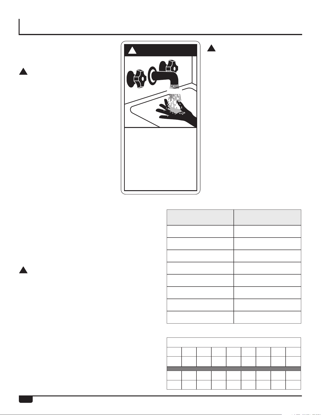
Water temperature over 125°
can
cause severe burns
instantly or
death from scalds.
Children, disabled and elderly are
at highest risk of being scalded.
See instruction manual before
setting temperature at water
heater.
Feel water before bathing or
showering.
Temperature limiting valves are
available, see manual.
BURN
F
!
CAUTIONS:
• This water heater must only be used
with the following water supply sys-
tem conditions:
– With clean, potable water free of
corrosive chemicals, sand, dirt,
or other contaminants.
– With inlet water temperatures
above 32°F (0°C), but not
exceeding 120°F (49°C).
– DO NOT reverse the hot and
cold water connections. The
water heater will not operate.
• Even when drained properly, a small
amount of water will remain in the
water heater. In cold weather con-
ditions, this water can freeze. If this
happens, allow the defrost protec-
tion on the heater at least 30 min-
utes to melt the frozen water or the
water heater may not work properly.
Water Supply
Safety
!
DANGERS:
• WATER TEMPERATURE SETTINGS
– Safety and energy conservation
are factors to be considered when
selecting the water temperature
setting of a water heater’s remote
control. Water temperatures above
125°F (52°C) can cause death or
severe burns from scalding. Be
sure to read and follow the warn-
ings outlined on the pictured label.
• There is a hot water scald poten-
tial if the water temperature is set
too high. Households with small
children, the disabled, or elderly
persons may require a 120°F (49°C)
or lower temperature setting to pre-
vent contact with “HOT” water.
• Before manually operating the relief
valve, make certain no one will be
exposed to the danger of the hot water released by
the valve. The water may be hot enough to create a
scald hazard. The water should be released into a
suitable drain to prevent injury or property damage.
• Failure to perform the recommended Routine
Preventive Maintenance can harm the proper oper-
ation of this water heater, which can cause carbon
monoxide dangers, excessive hot water tempera-
tures, and other potentially hazardous conditions.
!
WARNINGS:
• IMPORTANT: DO NOT apply heat to the HOT or COLD
water connections. If sweat connections are used,
sweat tubing to adapter before fitting adapter to the
water connections on heater. Any heat applied to the
water supply fittings will permanently damage the
internal components of the water heater.
• In case the pipe insulation is not rated for the appro-
priate weather conditions, install electric heat trac-
ing or equivalent to prevent freezing of the pipes.
DO NOT insulate or block the drain valve on the hot
outlet fitting. If the pipes are allowed to freeze, the
water heater and the pipes may malfunction or leak
due to freezing water.
• Failure to drain the water heater as described on
page 20 can cause serious personal injuries from
scalding and/or damage the water heater.
Time/Temperature Relationship in Scalds
Water
Temperature
Time to Produce a
Serious Burn
120°F (49°C) More than 5 minutes
125°F (52°C) 1 1/2 to 2 minutes
130°F (54°C) About 30 seconds
135°F (57°C) About 10 seconds
140°F (60°C) Less than 5 seconds
145°F (63°C) Less than 3 seconds
150°F (66°C) About 1 1/2 seconds
155°F (68°C) About 1 second
Table courtesy of Shriners Burn Institute
Temperature Conversion Chart °F/°C
85 100 102 104 106 108 110 112 °F
29 38 39 40 41 42 43 44 °C
114 116 118 120 125 130 140 °F
46 47 48 49 52 54 60 °C

IMPORTANT SAFETY INFORMATION
5
!
WARNINGS:
• The installation of gas piping must conform to local
utility company requirements and/or in the absence
of local codes, use the latest edition of National Fuel
Gas Code (NFGC), ANSI Z223.1/NFPA 54, or CAN/
CSA B149.1, Natural Gas and Propane Installation
Code.
• If inlet gas pressure is out of allowable range [4.0”
w.c. (1.0kPa) – 10.5” w.c. (2.6kPa)] for Natural Gas, or
[8.0” w.c. (2.0kPa) – 13.0” w.c. (3.2kPa)] for LP gas, a
gas pressure regulator must be installed to maintain
the allowable inlet gas pressure.
• Should overheating occur or the gas supply fail to
shut off, turn off the manual gas control valve to the
water heater.
!
CAUTIONS:
• DO NOT attempt repair of electrical wiring, gas pip-
ing, remote control, burners, vent connectors, or
other safety devices. Refer repairs to qualified ser-
vice personnel.
• Turn off the manual gas shut-off valve if the water
heater has been subjected to overheating, fire, flood,
physical damage, or if the gas supply fails to shut
off.
• DO NOT turn on the water heater unless the water
and gas supplies are completely opened.
NOTICE:
• The factory setting allows operating temperatures
between 100°F (38°C) and 120°F (49°C). Temperatures
of 85°F (29°C) and up to 140°F (60°C) can be
achieved with the MAIN (UMC-117) remote control.
Temperatures of 85°F (29°C) can be achieved with
the Bath (USC-117 or USC2-117) remote control.
Only qualified service personnel should perform this
adjustment. Only factory-authorized remote con-
trol(s) should be used.
Natural Gas and Liquefied Petroleum Safety
!
DANGERS:
• Never attempt to convert the water heater from nat-
ural gas to LP. The water heater should only use the
fuel type in accordance with listing on data plate—
natural gas for natural gas units and LP for LP units.
Any other fuel usage will result in death or serious
personal injury from fire and/or explosion. This water
heater is not certified for any other fuel type.
• Both natural gas and propane (LP) have an odorant
added to aid in detecting a gas leak. Some people
may not physically be able to smell or recognize
this odorant. If you are unsure or unfamiliar with
the smell of natural gas or LP, ask the gas supplier.
Other conditions, such as “odorant fade,” which
causes the odorant to diminish in intensity, can also
hide or camouflage a gas leak.
• Water heaters using LP gas are different from natural
gas models. A natural gas water heater will not func-
tion safely on LP and vice versa.
• LP water heaters should not be installed below
grade (for example, in a basement) if such installa-
tion is prohibited by federal, state, and/or local laws,
rules, regulations, or customs.
• LP must be used with great caution. It is heavier than
air and will collect first in lower areas, making it hard
to detect at nose level.
• Before attempting to light the water heater, make
sure to look and smell for gas leaks. Use a soapy
solution to check all gas fittings and connections.
Bubbling at a connection indicates a leak that must
be corrected. When smelling to detect a gas leak, be
sure to also sniff near the floor.
• Gas detectors are recommended in LP and natural
gas applications and their installation should be in
accordance with the detector manufacturer’s recom-
mendations and/or local laws, rules, regulations, or
customs.
• Combustible materials, such as clothing, cleaning
materials, or flammable liquids, must not be placed
in the vicinity of the water heater.
• If a gas leak is present or suspected:
– DO NOT attempt to find the cause yourself.
– Never use an open flame to test for gas leaks.
The gas can ignite resulting in death, personal
injury, or property damage.
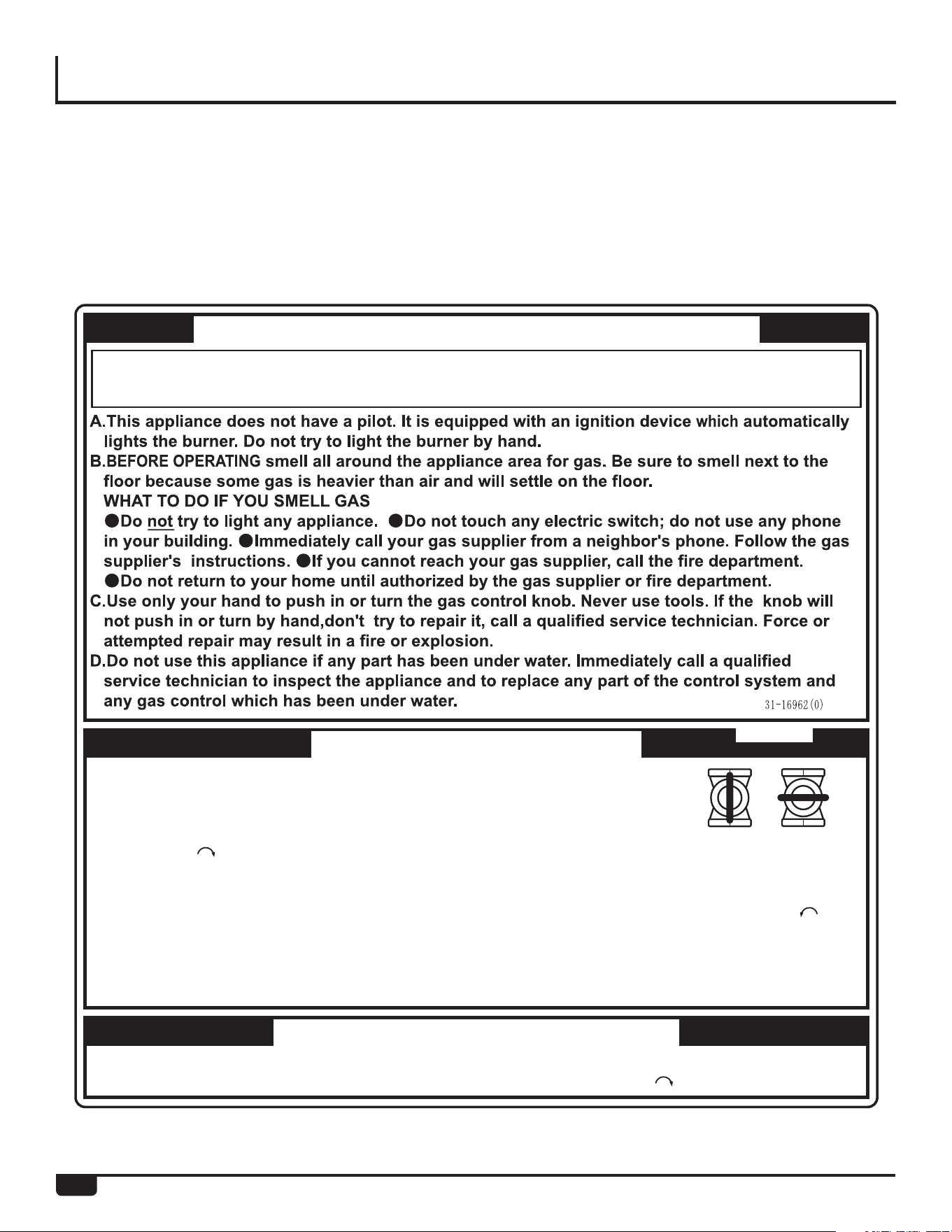
– Follow the steps listed under “What to Do If
You Smell Gas” found on the front cover of this
manual.
IMPORTANT SAFETY INFORMATION
6
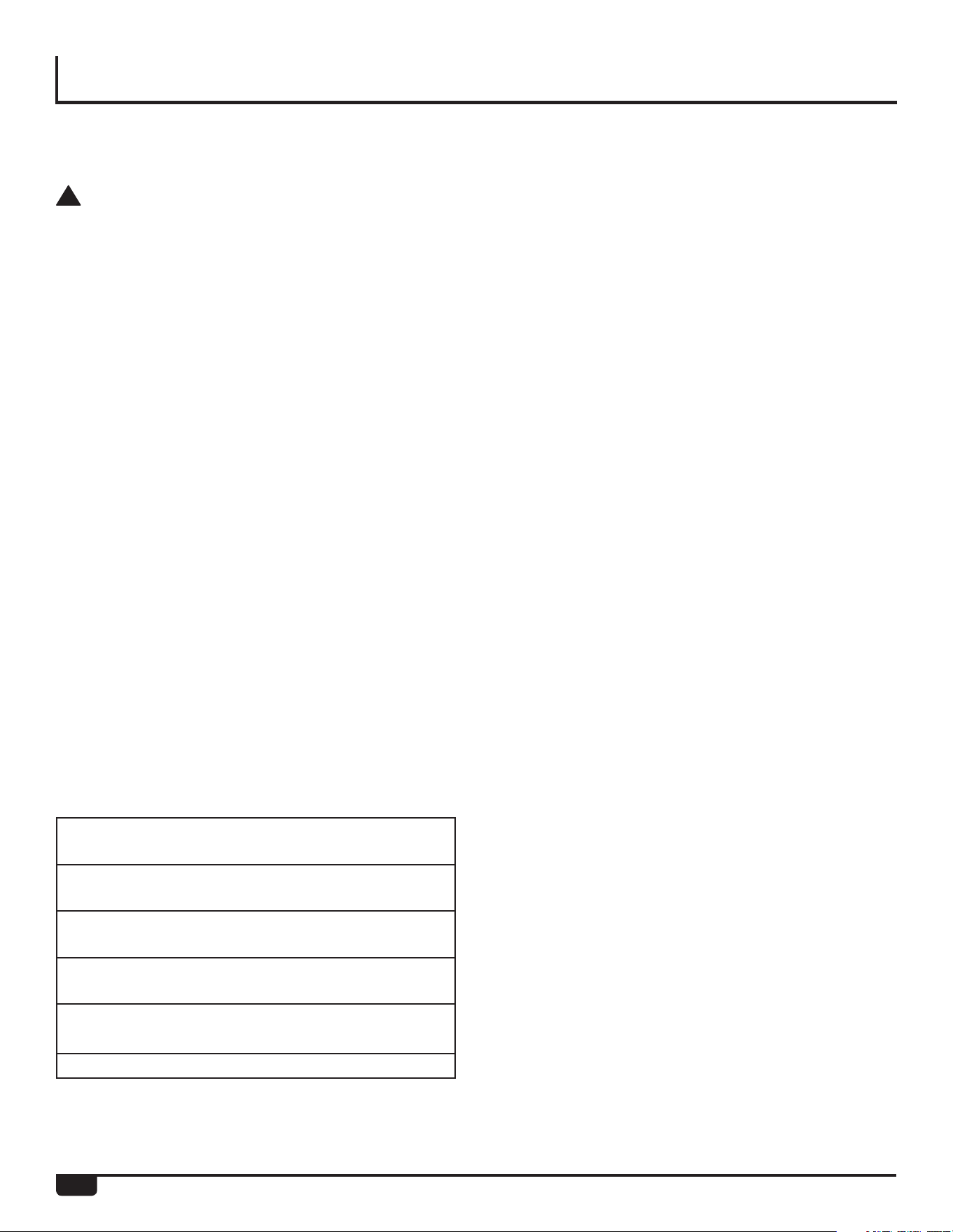
Before operating this water heater, be sure to read and
follow the instructions on the label pictured below and all
other labels on the water heater, as well as the warnings
printed in this manual. Failure to do so can result in unsafe
operation of the water heater, resulting in death, personal
injury, or property damage. Should you have any problems
reading or following the instructions in this manual, STOP
and get help from a qualified service technician.
WARNING
: If you do not follow these instructions exactly, a fire or explosion may result
causing property damage, personal injury or loss of life.
FOR YOUR SAFETY READ BEFORE OPERATING
1.STOP! Read the safety information above on this label.
2.Turn off all electric power to the appliance.
3.Do not attempt to light the burner by hand.
4.Turn the Gas Shutoff Valve located on the outside of the unit
clockwise to the "OFF" position.
5.Wait five (5) minutes to clear out any gas. If you then smell gas, STOP! Follow "B" in
the safety information above on this label. If you don't smell gas, go to the next step.
6.Turn the Gas Shutoff Valve located on the outside of the unit counterclockwise to
the "ON" position.
7.Turn on all electric power to the appliance.
8.If the appliance will not operate, follow the instructions "To Turn Off Gas To Appliance"
and call your service technician or gas supplier.
TO TURN OFF GAS TO APPLIANCE
1
.
Turn off all electric power to the appliance if service is to be performed.
2
.
Turn
the
Gas
Shutoff
Valve
located
on
the
outside
of
the
unit
clockwise to
the
"OFF"
position.
GAS SHUTOFF
VALVE
OPEN CLOSE
OPERATING INSTRUCTIONS

IMPORTANT SAFETY INFORMATION
7
Electrical Safety
!
DANGER:
• Shock Hazard – Make sure the electrical power to the
water heater is off to avoid electric shock that will
result in death or serious personal injury.
!
WARNINGS:
• For your safety, the information in this manual must
be followed to minimize the risk of fire, explosion,
or electric shock that can result in death, personal
injury, and/or property damage.
• Field wiring connections and electrical grounding
must comply with local codes or, in the absence of
local codes, with the latest edition of the National
Electrical Code, ANSI/NFPA 70, or in Canada,
Canadian Electrical Code, CAN/CSA C22.1, Part 1.
!
CAUTIONS:
• Label all wires prior to disconnecting for service.
Wiring errors can cause dangerous and improper
operation. Verify correct operation after servicing.
• For your safety, burner inspection and cleaning
should be performed only by qualified service per-
sonnel.
• Make certain the power to the water heater is OFF
before removing the unit cover panel. Exposed
electrical components and moving parts can cause
personal injuries.
• For your safety, DO NOT attempt repair of electrical
wiring, gas piping, remote control, burners, vent
connectors, or other safety devices. Refer repairs to
qualified service personnel.
California law requires that water heaters must be
braced, anchored, or strapped to resist falling or hor-
izontal displacement due to earthquake motions. For
water heaters up to 52-gallon capacity, a brochure
with generic earthquake bracing instructions can be
obtained from: Office of the State Architect, 1102 Q
Street, Suite 5100, Sacramento, CA 95814, or you may
call 916-445-8100 or ask a water heater dealer.
However, applicable local codes shall govern installa-
tion. For residential water heaters of a capacity greater
than 52 gallons or tankless-style, consult the local build-
ing jurisdiction code for acceptable bracing procedures.
For Installations in the State of California
IMPORTANT SAFETY INFORMATION
8
!
WARNINGS:
• This water heater must be installed in accordance
with these instructions, local codes, utility company
requirements and/or in the absence of local codes,
use the latest edition of the American National
Standard/National Fuel Gas Code (NFGC), ANSI
Z223.1 and National Fire Protection Association,
NFPA 54, or in Canada, CAN/CSA B149.1, Natural
Gas and Propane Installation Code, and the latest
edition of the National Electrical Code, ANSI/NFPA
70, or in Canada, Canadian Electrical Code, CAN/
CSA C22.1, Part 1.
• If local codes require the application of external
insulation blanket kits, carefully follow the manufac-
turer’s installation instructions included with the kit.
Only use blanket kits that are approved for use with
your water heater.
• For your safety, DO NOT attempt to disassemble this
water heater for any reason. Improper adjustments,
alterations, service, or maintenance can cause death,
personal injury, or property damage.
Safety Precautions
• Read this manual entirely before installing and/or
operating the water heater.
• Use this water heater only for its intended purpose
as described in this Use and Care Manual.
• Have the installer show you the location of the gas
shut-off valve and how to shut it off if necessary.
Turn off the manual shut-off valve if the water heater
has been subjected to overheating, fire, flood, physi-
cal damage, or if the gas supply fails to shut off.
• Be sure your water heater is properly installed in
accordance with local codes and the provided instal-
lation instructions.
• DO NOT attempt to repair or replace any part of your
water heater unless it is specifically recommended
in this manual. All other servicing should be referred
to a qualified service technician.
Product Information
For Your Records
Write down and save the following product information
along with the original sales slip and/or cancelled check.
The model and serial numbers can be found on the top
label on the right side of the water heater.
MODEL NUMBER:
SERIAL NUMBER:
DATE OF INSTALLATION:
INSTALLING COMPANY/PHONE NUMBER:
PLUMBING CONTRACTOR/PHONE NUMBER:
See page 43 for additional service information.
General Installation and Maintenance Safety

9
DESCRIPTION
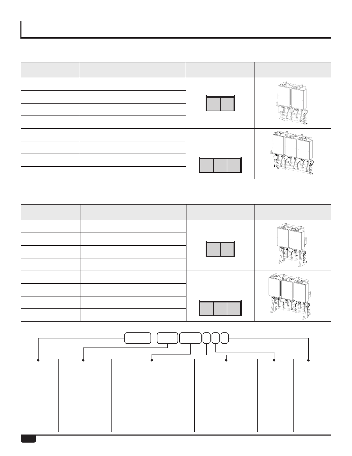
Rheem Tankless Rack Systems (RTR) include wall mount-
ed and free standing configurations. The wall mounted
rack systems are available for 2 or 3 water heaters. Free
standing rack systems are available for 2, 3, 4, 5 or 6 water
heaters.
The RTR can be ordered with Rheem’s Common Venting
System, which consists of the CVent exhaust venting and
PP or PVC intake venting. Up to 6 tankless units can share
the same CVent system with the RTR.
The RTR features design details that make installation
simple and straightforward.
• Maneuverability: Fits, fully assembled, through stan-
dard 32-inch doorways and on elevators.
• Flexibility: Available in both wall-mount or freestand-
ing design for indoor and outdoor installations.
Preassembled gas and water manifolds are properly
sized to maintain optimum performance.
• The racks are constructed of powder-coated gal-
vanized steel to stand up to the most demanding
commercial environments, while minimizing weight.
NOTE:
The RTR is designed to be used with Rheem tankless
water heaters only. DO NOT mount non-Rheem water
heaters on the RTR.
10
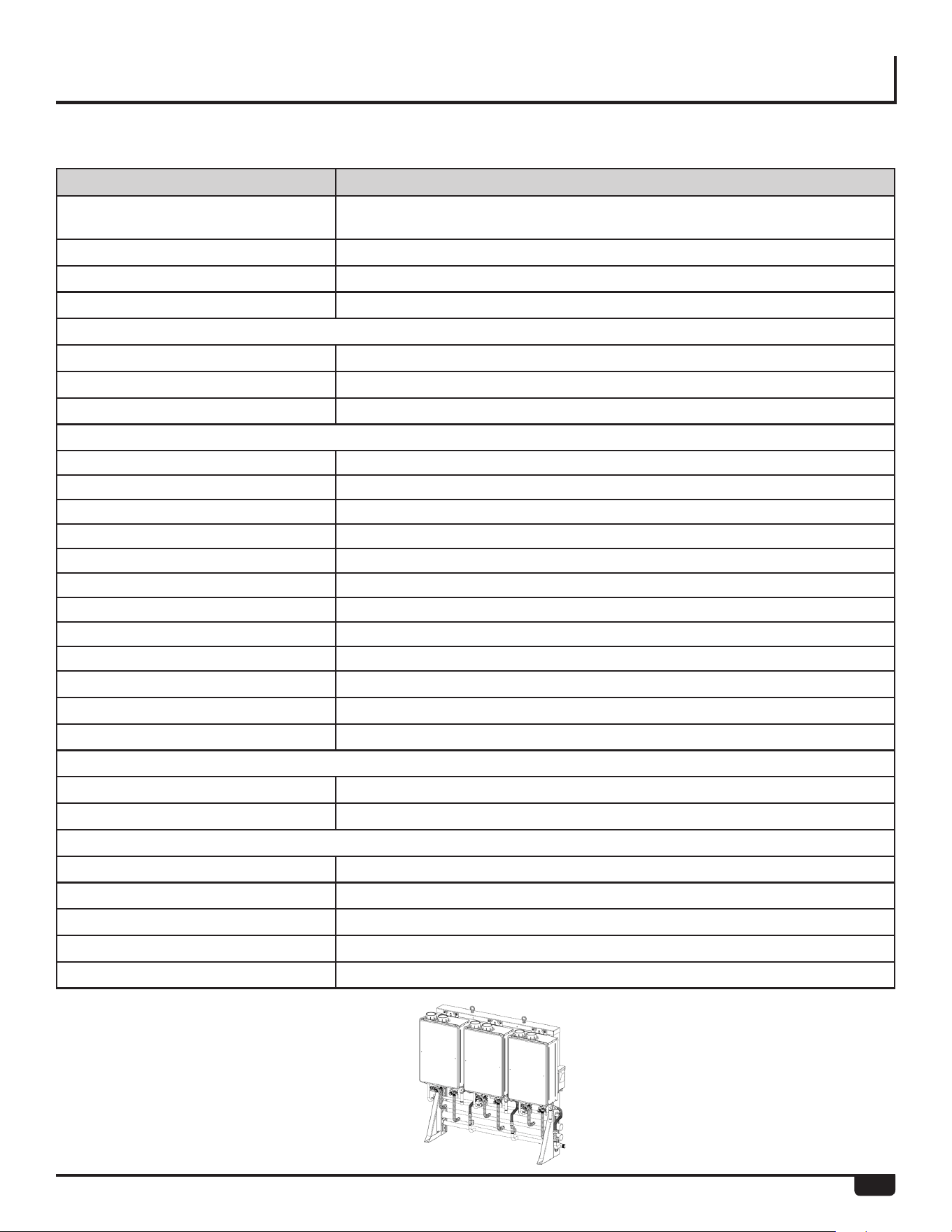
RTR PART NOS. AND MAIN COMPONENTS
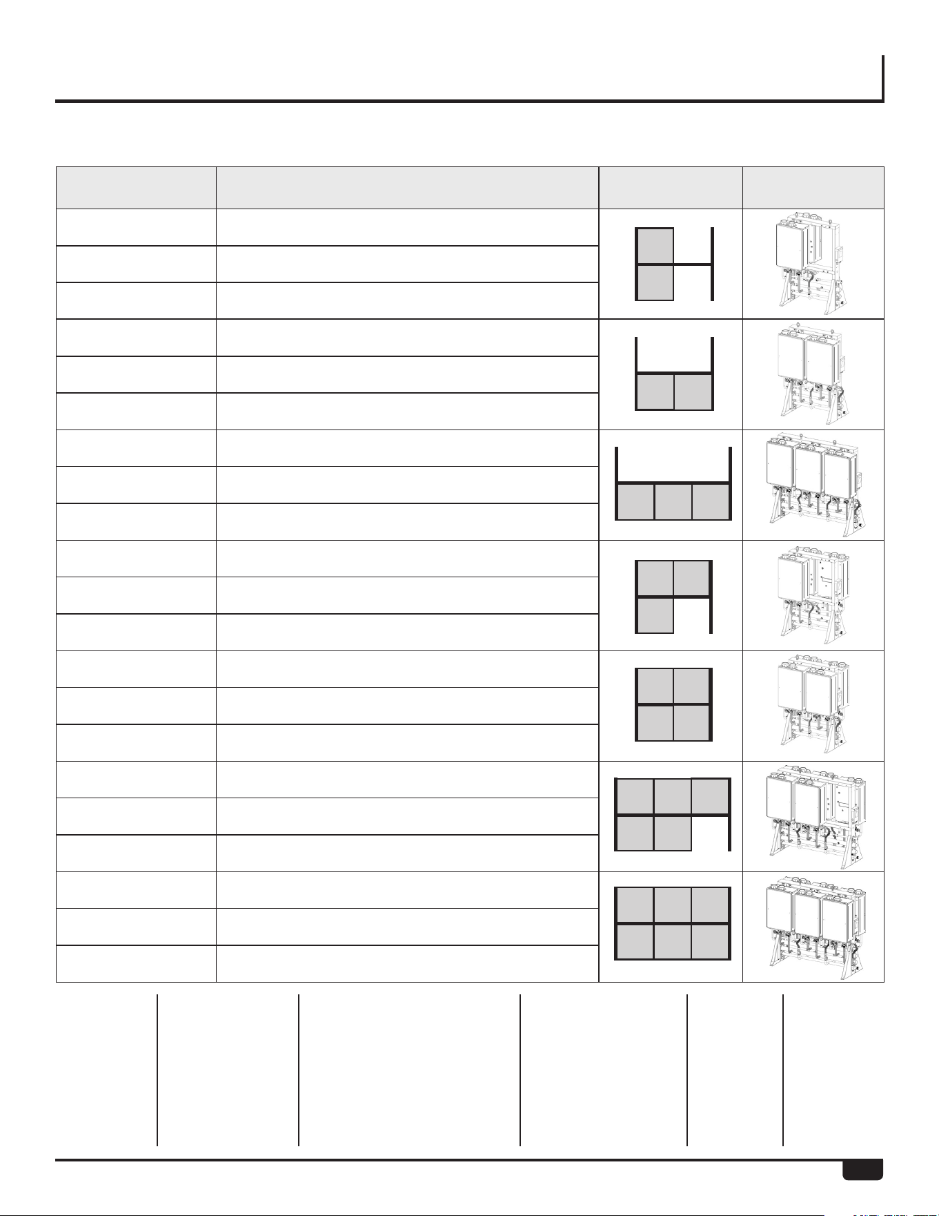
Part No.* Rack Type Configuration Illustration
RTR-WH220DVLN 2-unit interior wall hanging rack, NG
RTR-WH220XLN 2-unit exterior wall hanging rack, NG
RTR-WH220DVLP 2-unit interior wall hanging rack, LP
RTR-WH220XLP 2-unit exterior wall hanging rack, LP
RTR-WH330DVLN 3-unit interior wall hanging rack, NG
RTR-WH330XLN 3-unit exterior wall hanging rack, NG
RTR-WH330DVLP 3-unit interior wall hanging rack, LP
RTR-WH330XLP 3-unit exterior wall hanging rack, LP
Part No.* Rack Type Configuration Illustration
RTR-WM220DVLN 2-unit interior wall mount rack, NG
RTR-WM220XLN 2-unit exterior wall mount rack, NG
RTR-WM220DVLP 2-unit interior wall mount rack, LP
RTR-WM220XLP 2-unit exterior wall mount rack, LP
RTR-WM330DVLN 3-unit interior wall mount rack, NG
RTR-WM330XLN 3-unit exterior wall mount rack, NG
RTR-WM330DVLP 3-unit interior wall mount rack, LP
RTR-WM330XLP 3-unit exterior wall mount rack, LP
Tankless Rack Wall Hanging
Tankless Rack Inline Wall Mount
System:
RTR = Rheem
Tankless Rack
Configuration:
FS = Free standing
WM = Wall mount
WH = Wall hanging
Venting:
DV=Direct Vent / Indoor
X=Outdoor
Emissions:
L=Low NOx
Gas Type:
P=Propane
N=Natural Gas
Units on rack (max tankless for
configuration, units on front,
units on back)
First Digit = 2,3,4,6 = Max possi-
ble units for configuration
Second Digit = 1,2,3 = Actual
units on front
Third Digit = 0,1,2,3 = Actual
units on back
RTR-WM330XLP
11
Part No.* Rack Type Configuration Illustration
RTR-FS411DVLN 2-unit interior free standing rack, NG
RTR-FS411XLN 2-unit exterior free standing rack, NG
RTR-FS411XVLP 2-unit exterior free standing rack, LP
RTR-FS420DVLN 2-unit INLINE interior free standing rack, NG
RTR-FS420XLN 2-unit INLINE exterior free standing rack, NG
RTR-FS420XLP 2-unit INLINE exterior free standing rack, LP
RTR-FS630DVLN 3-unit INLINE interior free standing rack, NG
RTR-FS630XLN 3-unit INLINE exterior free standing rack, NG
RTR-FS630XLP 3-unit INLINE exterior free standing rack, LP
RTR-FS421DVLN 3-unit interior free standing rack, NG
RTR-FS421XLN 3-unit exterior free standing rack, NG
RTR-FS421XLP 3-unit exterior free standing rack, LP
RTR-FS422DVLN 4-unit interior free standing rack, NG
RTR-FS422XLN 4-unit exterior free standing rack, NG
RTR-FS422XLP 4-unit exterior free standing rack, LP
RTR-FS632DVLN 5-unit interior free standing rack, NG
RTR-FS632XLN 5-unit exterior free standing rack, NG
RTR-FS632XLP 5-unit exterior free standing rack, LP
RTR-FS633DVLN 6-unit interior free standing rack, NG
RTR-FS633XLN 6-unit exterior free standing rack, NG
RTR-FS633XLP 6-unit exterior free standing rack, LP
RTR PART NOS. AND MAIN COMPONENTS
Tankless Rack Freestanding
System:
RTR = Rheem
Tankless Rack
Configuration:
FS = Free standing
WM = Wall mount
WH = Wall hanging
Venting:
DV=Direct Vent / Indoor
X=Outdoor
Emissions:
L=Low NOx
Gas Type:
P=Propane
N=Natural Gas
Units on rack (max tankless for
configuration, units on front,
units on back)
First Digit = 2,3,4,6 = Max possi-
ble units for configuration
Second Digit = 1,2,3 = Actual
units on front
Third Digit = 0,1,2,3 = Actual
units on back
12
SPECIFICATIONS
Left BackFront
Model Configuration Illustration
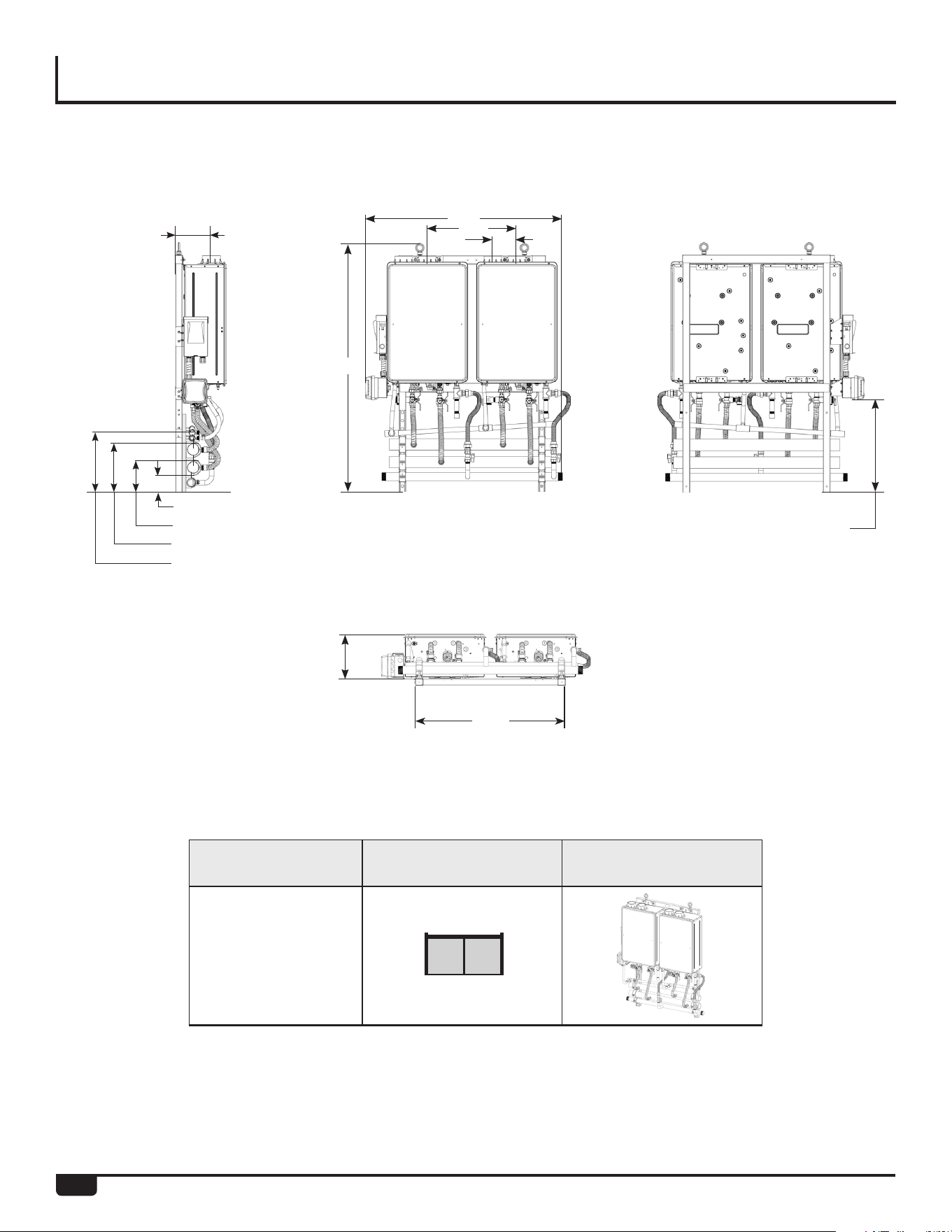
RTR-WH2
2 Unit Wall Hanging Frame
Bottom
54.30”
45.38”
33.63”
11.50”
20.50”
5.50”
11.00” (Hot)
15.38” (Condensate)
7.00” (Cold)
3.63” (Gas)
8.00”
21.31” (Electrical Box)
13
SPECIFICATIONS
2 Unit Wall Hanging Frame
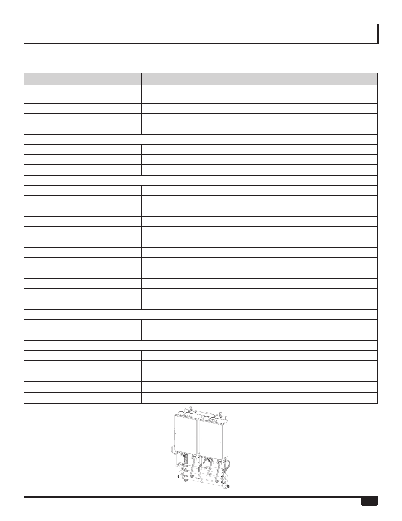
Model RTR-WH2*
Water Heater Model RTGH-CM95DVLN, RTGH-CM95DVLP, RTGH-CM95XLN,RTGH-CM95XLP
(Indoor NG/LP) (Outdoor NG/LP)
Crate Dimensions (HxLxD) - in 21 X 53 X 65
Weight - Fully Assembled - lbs 220
Weight - Shipping (total) - lbs 320
Rack Frame
Frame Material 16 Gauge Galvanized Steel
Frame Finish Powder Coat
Color Gray
Water, Gas amd Condensate Connections
Hot Water Trunk Line Diameter 2 - 1/2”
Cold Water Trunk Line Diameter 2 - 1/2”
Hot Water Trunk Line Material Rigid Copper
Cold Water Trunk Line Material Rigid Copper
Water Trunk Connection Type 2 - 1/2” PIPE
Gas Trunk Line Diameter 1-1/2”
Gas Trunk Connection Type 1-1/2” MNPT
Gas Trunk Line Material Sch 40 Steel
Gas Branch Line Material Sch 40 Steel
Condensate Trunk Line Diameter 3/4”
Condensate Trunk Line Material Sch-40 PVC
Condensate Trunk Connection Type 3/4” Pipe
Electrical
Voltage 120V AC / 60Hz
Maximum Current (Amperes) 8
BTU and Flow Rates
Number of Tankless Water Heaters 2
Flow rate @ 70°F rise (gpm) 10.7
Flow rate@ 100° F rise (gpm) 7.5
Minimum input rate (Btuh)
11,000
Maximum input rate (Btuh)
399,800
*Refer to page 10 for Part No.
14
SPECIFICATIONS
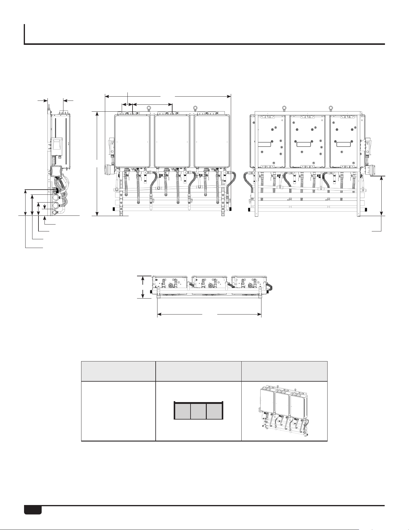
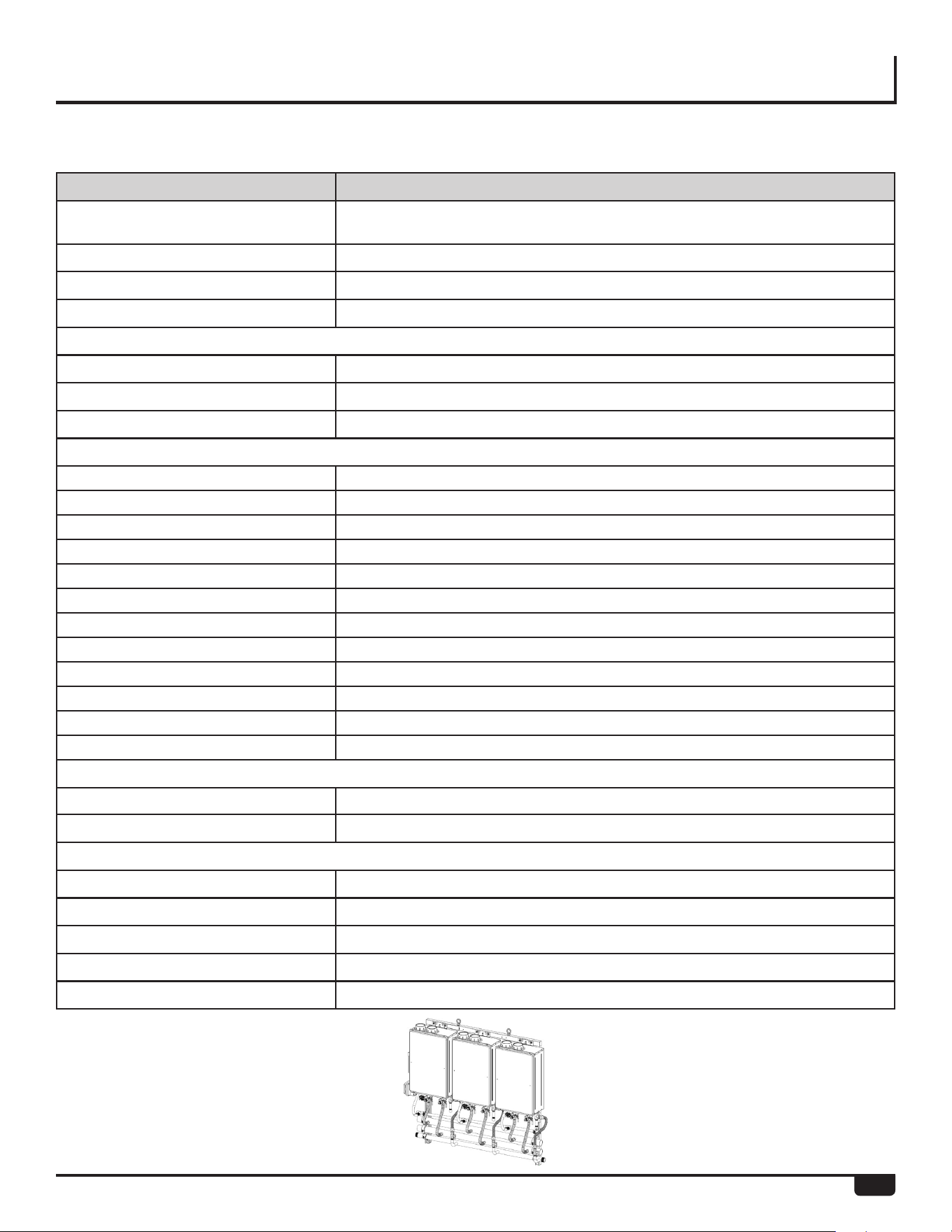
Left BackFront
Bottom
Model Configuration Illustration
RTR-WH3
3 Unit Wall Hanging Frame
8.00”
54.25”
11.50”
11.00”(Hot)
7.00”(Cold)
3.63”(Gas)
65.57”
20.50”
5.50”
54.30”
15.38” (Condensate)
21.31” (Electrical Box)
15
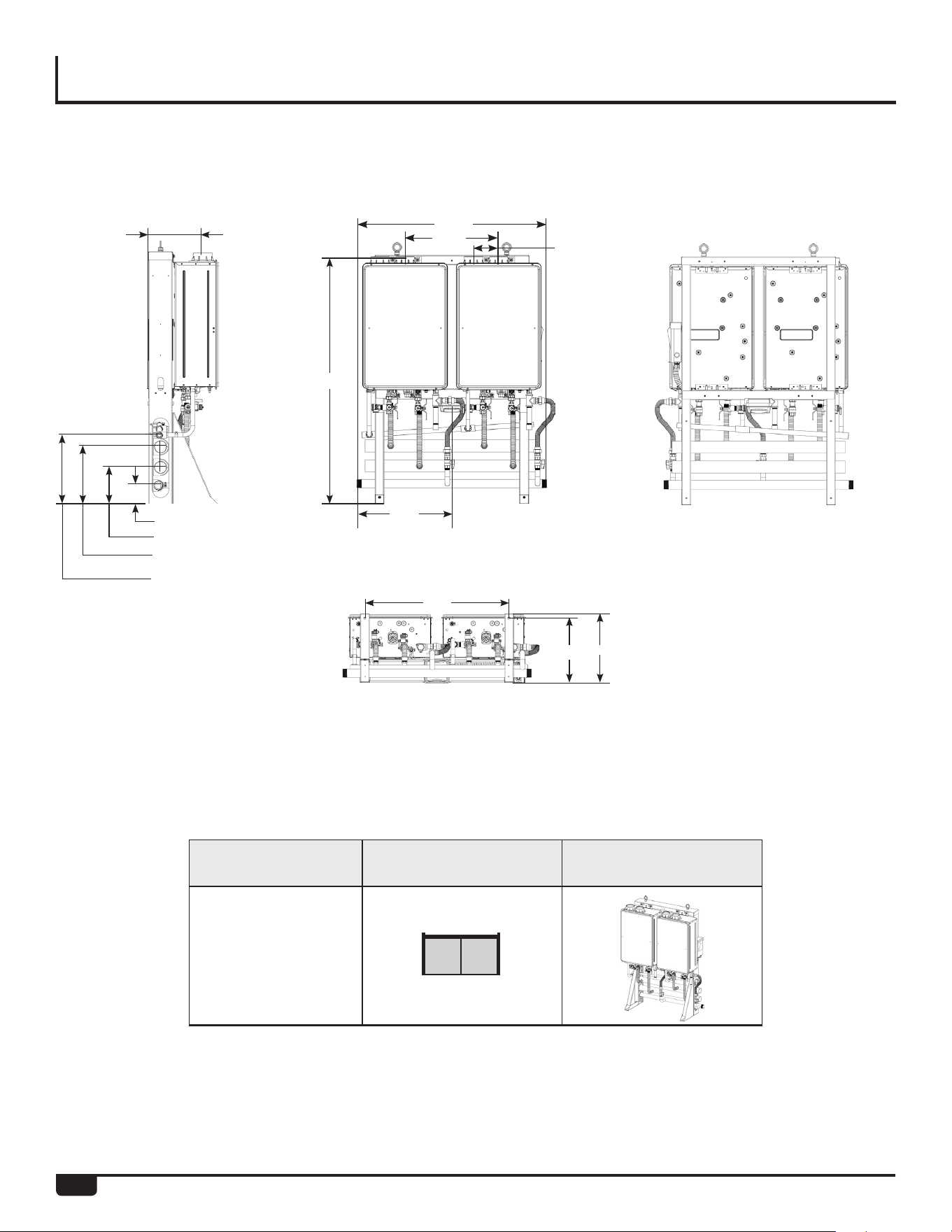
SPECIFICATIONS
3 Unit Wall Hanging Frame
Model RTW-WH3*
Water Heater Model RTGH-CM95DVLN, RTGH-CM95DVLP, RTGH-CM95XLN,RTGH-CM95XLP
(Indoor NG/LP) (Outdoor NG/LP)
Crate Dimensions (HxLxD) - in 21 X 73 X 65
Weight - Fully Assembled - lbs 310
Weight - Shipping (total) - lbs 430
Rack Frame
Frame Material 16 Gauge Galvanized Steel
Frame Finish Powder Coat
Color Gray
Water, Gas and Condensate Connections
Hot Water Trunk Line Diameter 2 - 1/2”
Cold Water Trunk Line Diameter 2 - 1/2”
Hot Water Trunk Line Material Rigid Copper
Cold Water Trunk Line Material Rigid Copper
Water Trunk Connection Type 2 - 1/2” PIPE
Gas Trunk Line Diameter 1-1/2”
Gas Trunk Connection Type 1-1/2” MNPT
Gas Trunk Line Material Sch 40 Steel
Gas Branch Line Material Sch 40 Steel
Condensate Trunk Line Diameter 3/4”
Condensate Trunk Line Material Sch-40 PVC
Condensate Trunk Connection Type 3/4” Pipe
Electrical
Voltage 120V AC / 60Hz
Maximum Current (Amperes) 12
BTU and Flow Rates
Number of Tankless Water Heaters 3
Flow rate @ 70°F rise (gpm) 16.1
Flow rate@ 100° F rise (gpm) 11.3
Minimum input rate (Btuh)
11,000
Maximum input rate (Btuh)
599,700
*Refer to page 10 for Part No.
16
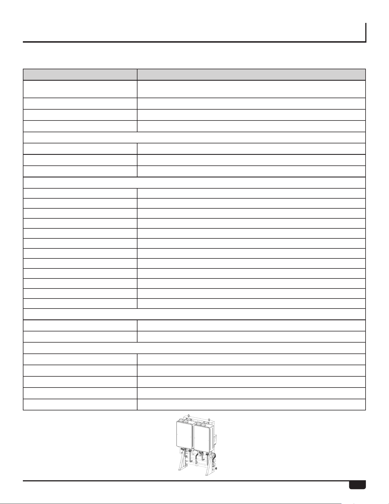
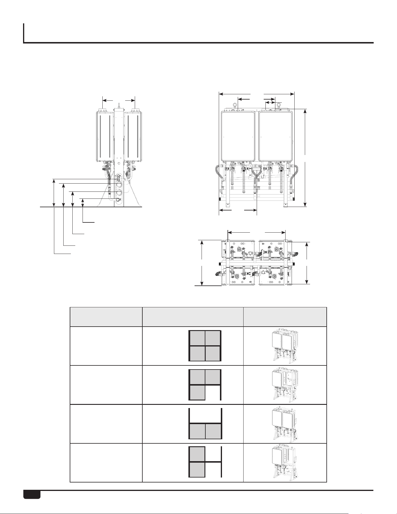
SPECIFICATIONS
Model Configuration Illustration
RTR-WM2
2 Unit Wall Mount Frame
Left BackFront
Bottom
11.63”
41.50”
20.50”
5.50”
4.50”(Gas)
54.30”
31.70”
14.25”
15.00”
8.38”(Cold)
12.75”(Hot)
15.38” (Condensate)
20.75”
(Electrical Box)
17
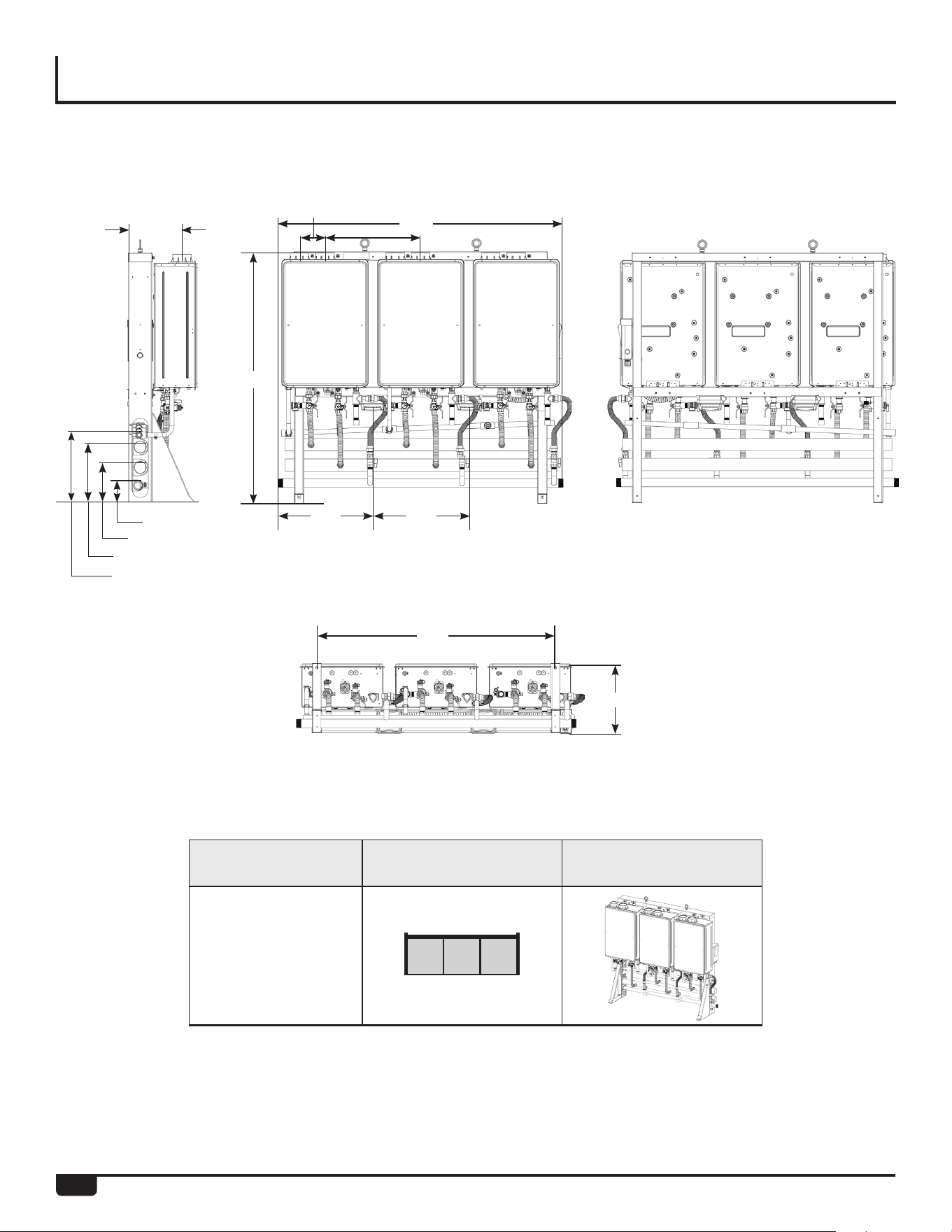
SPECIFICATIONS
2 Unit Wall Mount Frame
Model RTR-WM2*
Water Heater Model RTGH-CM95DVLN, RTGH-CM95DVLP, RTGH-CM95XLN,RTGH-CM95XLP
(Indoor NG/LP) (Outdoor NG/LP)
Crate Dimensions (HxLxD) - in 64 x 53 x 30
Weight - Fully Assembled - lbs 250
Weight - Shipping (total) - lbs 360
Rack Frame - Specifications
Frame Material 14 Gauge Galvanized Steel
Frame Finish Powder Coat
Color Gray
Water, Gas and Condensate Connections
Hot Water Trunk Line Diameter 2 - 1/2”
Cold Water Trunk Line Diameter 2 - 1/2”
Hot Water Trunk Line Material Rigid Copper
Cold Water Trunk Line Material Rigid Copper
Water Trunk Connection Type 2 - 1/2” PIPE
Gas Trunk Line Diameter 1-1/2”
Gas Trunk Connection Type 1-1/2” MNPT
Gas Trunk Line Material Sch 40 Steel
Gas Branch Line Material Sch 40 Steel
Condensate Trunk Line Diameter 3/4”
Condensate Trunk Line Material Sch-40 PVC
Condensate Trunk Connection Type 3/4” Pipe
Electrical
Voltage 120V AC / 60 Hz
Maximum Current (Amperes) 8
BTU and Flow Rates
Number of Tankless Water Heaters 2
Flow rate@ 70°F rise (gpm) 10.7
Flow rate@ 100°F rise (gpm)
7.5
Minimum input rate (Btuh) 11,000
Maximum input rate (Btuh) 399,800
*Refer to page 10 for Part No.
18
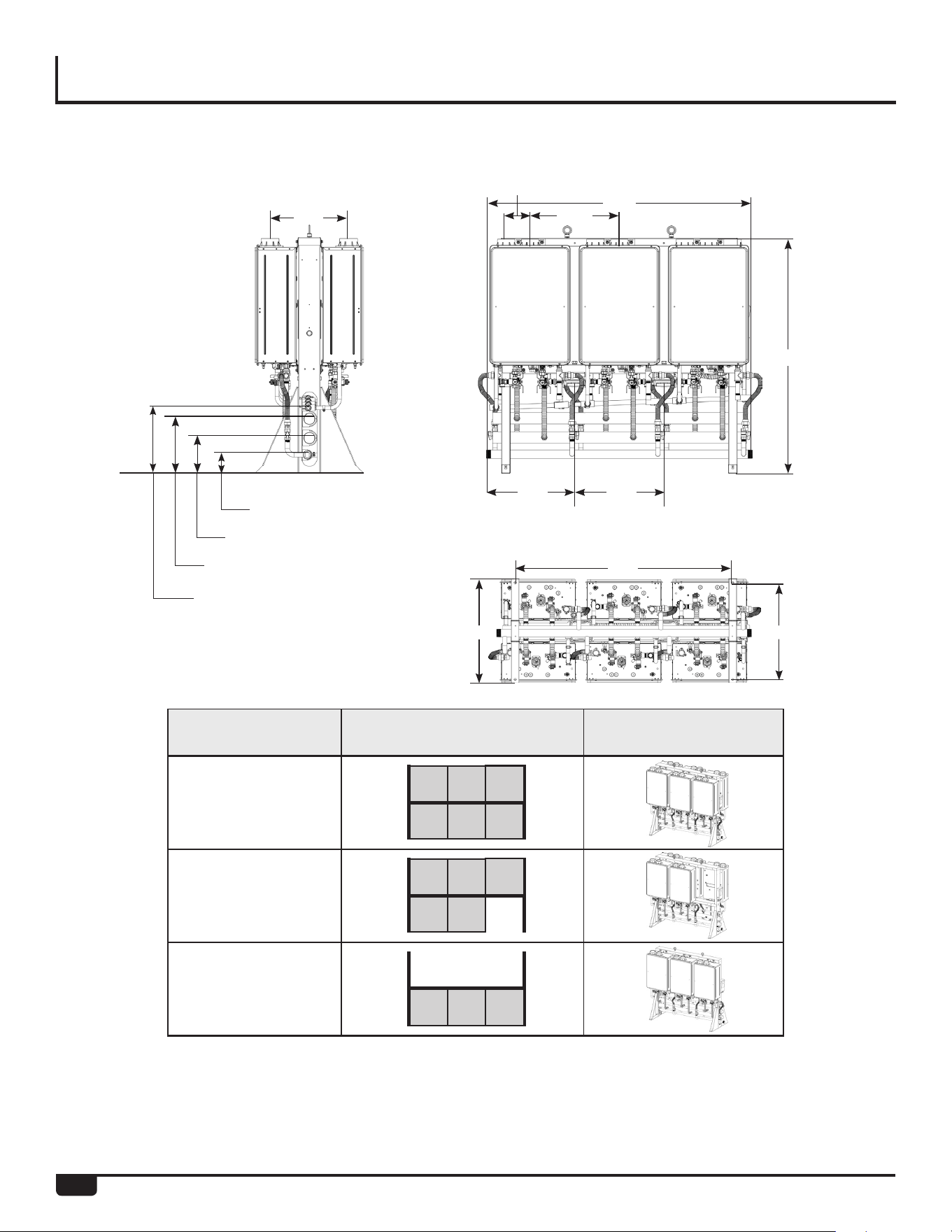
SPECIFICATIONS
Model Configuration Illustration
RTR-WM3
3 Unit Wall Mount Frame
Left BackFront
Bottom
11.63”
61.25”
20.42” 20.42”
52.30”
15.00”
20.50”
5.50”
54.30”
4.50” (Gas)
(Electrical Box) (Electrical Box)
8.38” (Cold)
12.75” (Hot)
15.38” (Condensate)
19
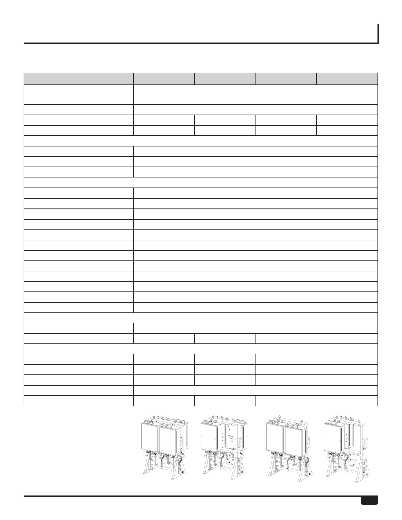
SPECIFICATIONS
3 Unit Wall Mount Frame
Model RTR-WM3*
Water Heater Model RTGH-CM95DVLN, RTGH-CM95DVLP, RTGH-CM95XLN,RTGH-CM95XLP
(Indoor NG/LP) (Outdoor NG/LP)
Crate Dimensions (HxlxD) - in 64 X 73 X 30
Weight - Fully Assembled - lbs 350
Weight - Shipping (total) - lbs 460
Rack Frame - Specifications
Frame Material 14 Gauge Galvanized Steel
Frame Finish Powder Coat
Color Gray
Water, Gas, and Condensate Connections
Hot Water Trunk Line Diameter 2 - 1/2”
Cold Water Trunk Line Diameter 2 - 1/2”
Hot Water Trunk Line Material Rigid Copper
Cold Water Trunk Line Material Rigid Copper
Water Trunk Connection Type 2 - 1/2” PIPE
Gas Trunk Line Diameter 1-1/2”
Gas Trunk Connection Type 1-1/2” MNPT
Gas Trunk Line Material Sch 40 Steel
Gas Branch Line Material Sch 40 Steel
Condensate Trunk Line Diameter 3/4”
Condensate Trunk Line Material Sch-40 PVC
Condensate Trunk Connection Type 3/4” Pipe
Electric Requirements
Voltage AC 120 Volts-60 Hz
Maximum Current (Amperes) 12
BTU and Flow Rates
Number of Tankless Water Heaters 3
Flow rate@ 70°F rise (gpm) 16.1
Flow rate@ 100°F rise (gpm)
11.3
Minimum input rate (Btuh) 11,000
Maximum input rate (Btuh) 599,700
*Refer to page 10 for Part No.
20
SPECIFICATIONS
Left Front
Model Configuration Illustration
RTR-FS422
RTR-FS421
RTR-FS420
RTR-FS411
4 Unit Free Standing Frame
Inline
(facing same
direction)
Back to Back
Bottom
11.88”
4.50” (Gas)
8.38” (Cold)
12.75” (Hot)
41.50”
31.70”
54.30”
25.00” 23.30”
5.50”
20.50”
15.38” (Condensate)
20.75”
(Electrical Box)
21
SPECIFICATIONS
4 Unit Free Standing Frame
Model RTR-FS422* RTR-FS421* RTR-FS420* RTR-FS411*
Water Heater Model RTGH-CM95DVLN, RTGH-CM95DVLP, RTGH-CM95XLN,RTGH-CM95XLP
(Indoor NG/LP) (Outdoor NG/LP)
Crate Dimensions (HxlxD) - in 62 X 55 X 36
Weight - Fully Assembled - lbs 420 330 240 240
Weight - Shipping (total) - lbs 530 440 350 350
Rack Frame - Specifications
Frame Material 14 Gauge Galvanized Steel
Frame Finish Powder Coat
Color Gray
Water, Gas and Condensate Connections
Hot Water Trunk Line Diameter 2 - 1/2”
Cold Water Trunk Line Diameter 2 - 1/2”
Hot Water Trunk Line Material Rigid Copper
Cold Water Trunk Line Material Rigid Copper
Water Trunk Connection Type 2 - 1/2” PIPE
Gas Trunk Line Diameter 1-1/2”
Gas Trunk Connection Type 1-1/2” MNPT
Gas Trunk Line Material Sch 40 Steel
Gas Branch Line Material Sch 40 Steel
Condensate Trunk Line Diameter 3/4”
Condensate Trunk Material Sch-40 PVC
Condensate Trunk Connection Type 3/4” Pipe
Electric
Voltage 120V AC/60 Hz
Maximum Current (Amperes) 16 12 N/A
BTU and Flow Rates
Number of Tankless Water Heaters 4 3 2
Flow rate @ 70°F rise (gpm) 21.5 16.1 10.7
Flow rate @ 100°F rise (gpm) 15.0 11.3 7.5
Minimum input rate (Btuh) 11,000
Maximum input rate (Btuh) 799,600 599,700 399,800
*Refer to page 11 for Part No.
22
SPECIFICATIONS
6 Unit Free Standing Frame
Model Configuration Illustration
RTR-FS633
RTR-FS632
RTR-FS630
Left Front
Bottom
11.88”
4.50” (Gas)
8.38” (Cold)
12.75” (Gas)
61.25”
53.30”
54.30”
23.30”25.00”
20.50”
5.50”
15.38” (Condensate)
20.42” 20.42”
(Electrical Box) (Electrical Box)
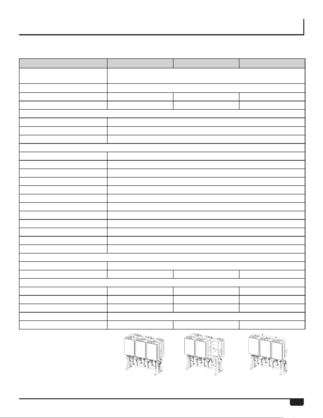
23
SPECIFICATIONS
6 Unit Free Standing Frame
Model RTR-FS633* RTR-FS632* RTR-FS630*
Water Heater Model RTGH-CM95DVLN, RTGH-CM95DVLP, RTGH-CM95XLN,RTGH-CM95XLP
(Indoor NG/LP) (Outdoor NG/LP)
Crate Dimensions (HxlxD) - in 64 X 73 X 30
Weight - Fully Assembled - lbs 620 530 350
Weight - Shipping (total) - lbs 760 670 490
Rack Frame - Specifications
Frame Material 14 Gauge Galvanized Steel
Frame Finish Powder Coat
Color Gray
Water, Gas and Condensate Connections
Hot Water Trunk Line Diameter 2-1/2”
Cold Water Trunk Line Diameter 2-1/2”
Hot Water Trunk Line Material Rigid Copper
Cold Water Trunk Line Material Rigid Copper
Water Trunk Connection Type 2-1/2” PIPE
Gas Trunk Line Diameter 1-1/2”
Gas Trunk Connection Type 1-1/2” MNPT
Gas Trunk Line Material Sch 40 Steel
Gas Branch Line Material Sch 40 Steel
Condensate Trunk Line Diameter 3/4”
Condensate Trunk Line Material Sch-40 PVC
Condensate Trunk Connection Type 3/4” Pipe
Electric
Voltage 120V AC/60 Hz
Maximum Current (Amperes) 24 20 12
BTU and Flow Rates
Number of Tankless Water Heaters 6 5 3
Flow rate @ 70°F rise (gpm) 32.2 26.8 16.1
Flow rate @ 100°F rise (gpm) 22.5 18.8 11.3
Minimum input rate (Btuh) 11,000
Maximum input rate (Btuh) 1,199,400 999,500 599,700
*Refer to page 11 for Part No.
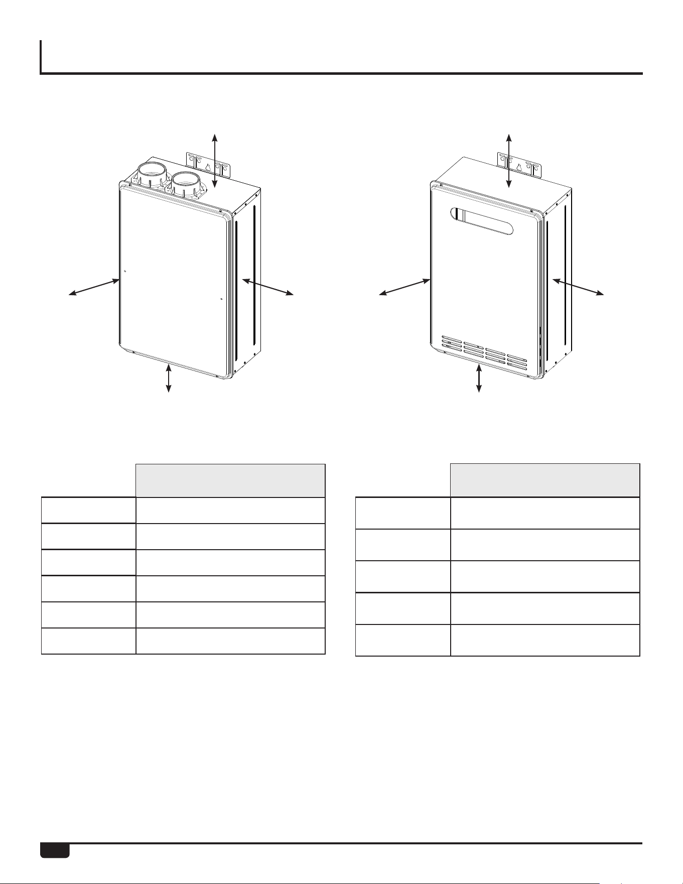
24
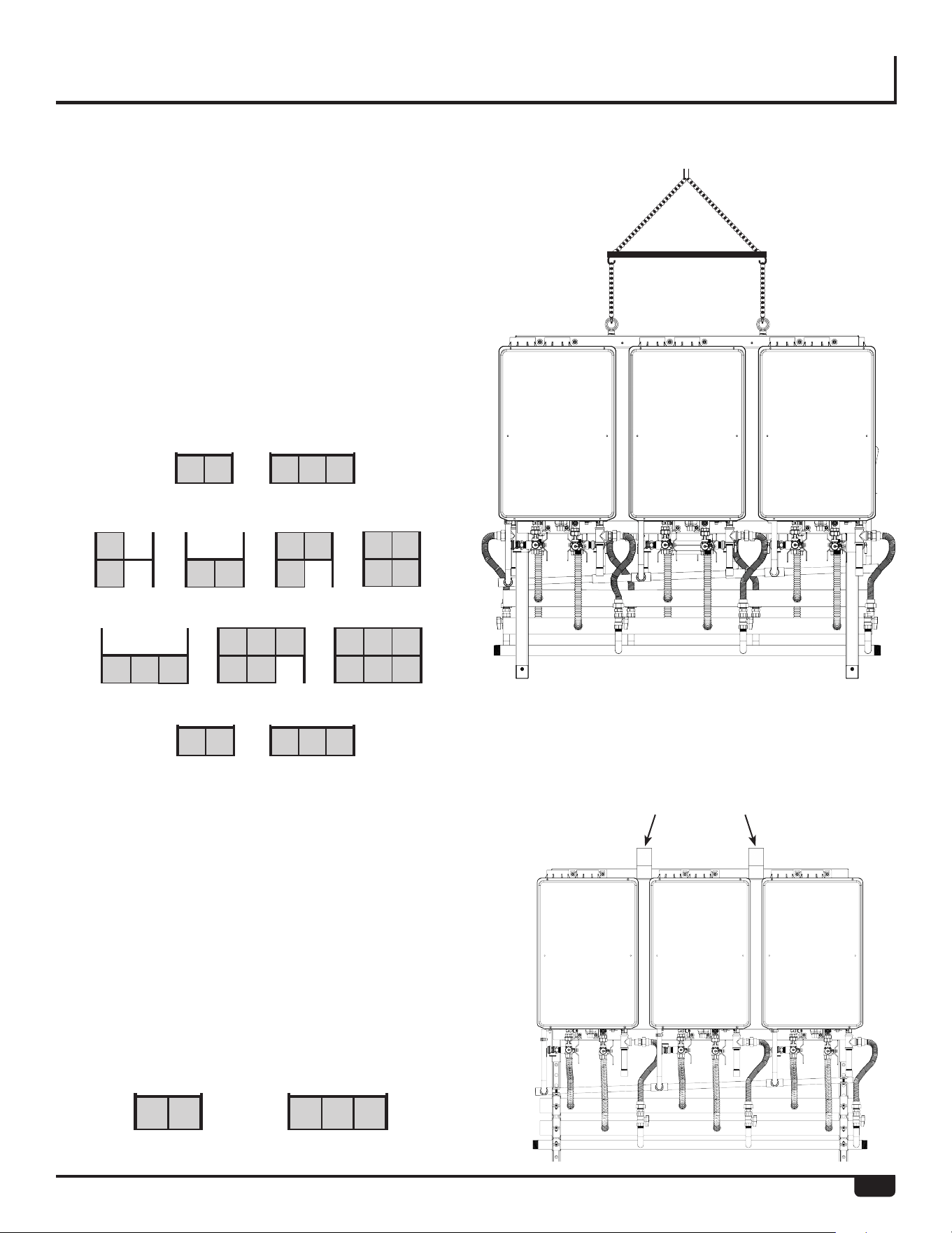
CLEARANCES
Install the rack system so that the clearances shown below (specified for the water heater in the RTGH-CM95DVLN, RTGH-
CM95DVLP, RTGH-CM95XLN and RTGH-CM95XLP high efficiency commercial condensing tankless water heater use and
care manual) are followed.
Indoor models: RTGH-CM95DVLN
RTGH-CM95DVLP
Outdoor models: RTGH-CM95XLN
RTGH-CM95XLP
To Combustibles and
Non-Combustibles inches (mm)
12 (305)
0 (zero)
12 (305)
1/2 (13)
12 (305)
0 (zero)
To Combustibles and
Non-Combustibles inches (mm)
12 (305)
0 (zero)
24 (610)
1/2 (13)
12 (305)
Top of Heater
Back of Heater
Front of Heater
Sides of Heater
Ground/Bottom
Vent
Top of Heater
Back of Heater
Front of Heater
Sides of Heater
Ground/Bottom
* 0 inches from vent components and condensate drain line.
The clearance for servicing is 24 inches in front of the
water heater.
For closet installation, clearance is 6 inches (152 mm from
the front of the water heater).
The clearance for servicing is 24 inches in front of the
water heater.
Top of Heater Top of Heater
Ground / Bottom Ground / Bottom
Side
of Heater
Side
of Heater
Front of
Heater
Front of
Heater
25
RTR-WM330
RTR-WH330
RTR-FS630
RTR-FS633
RTR-FS422
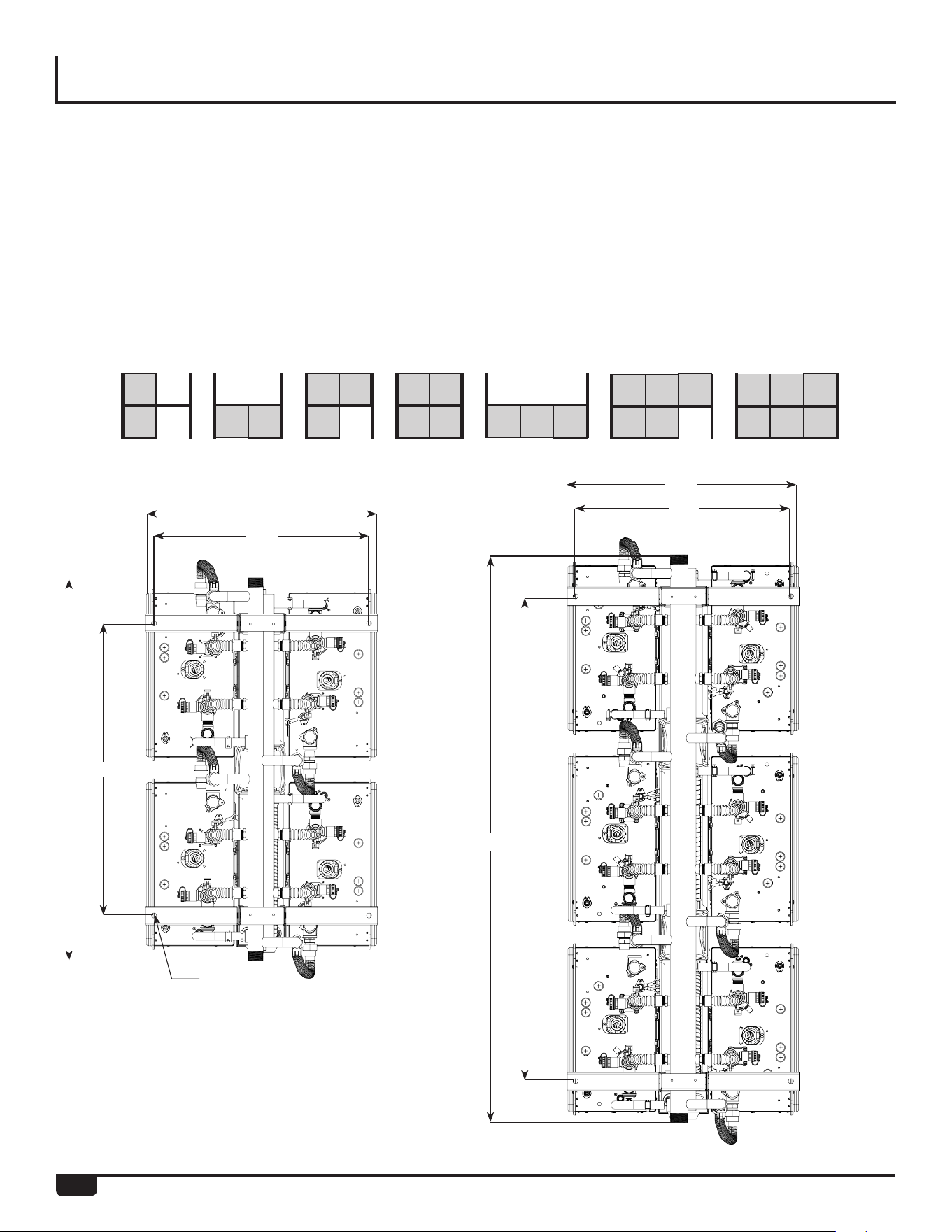
HOISTING (LIFTING LUGS)
Lugs are installed on the top side of the following racks for
hoisting and moving. The lines or cables to the lugs should
be at a 90° angle. Use a spreader lifting bar to hoist these
racks.
Weights of the complete assemblies are available in the
Specifications section of this manual.
Hoisting Straps
NOTE:
DO NOT hoist the crate or pallet.
NOTE:
DO NOT hoist the crate or palette.
Hoisting Straps - Optional
Models Available With
Lifting Lugs
Use hoisting straps looped around the top frame. Weights of
the complete assemblies are available in the Specifications
section of this manual.
RTR-WM220
RTR-WH220
RTR-FS411 RTR-FS420 RTR-FS412
RTR-WH2
RTR-WH3
RTR-FS623
26
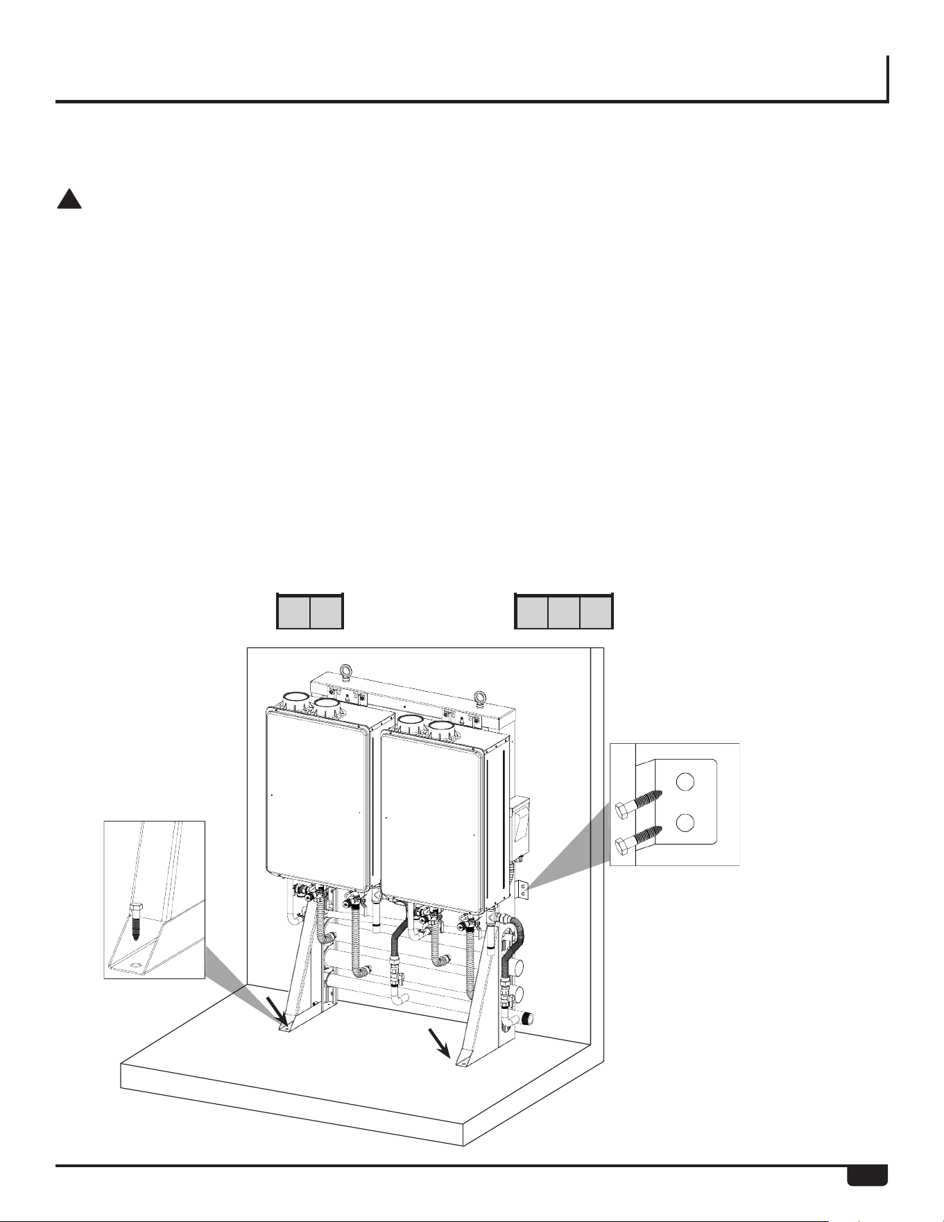
SECURING THE RACKS
All mechanical components shall be anchored and
installed in accordance with national and/or local codes
having jurisdiction . Base holes to secure all free stand-
ing RTR are 0.563 inches in diameter. Reference local
codes regarding minimum concrete thickness and use
appropriate expansion anchors that is capable of sup-
porting the RTR operating weight or where installation is
outdoor, anchors should be capable supporting the RTR
weight and wind shear. Reference and follow anchor
manufacturer’s use and installation requirements.
Securing Free Standing Racks
Free Standing Models Available
RTR-FS411 RTR-FS420 RTR-FS412 RTR-FS422 RTR-FS630 RTR-FS623 RTR-FS633
41.50”
61.25”
25.00”
25.00”
23.30”
23.30”
31.70”
53.30”
0.53”
27
SECURING THE RACKS
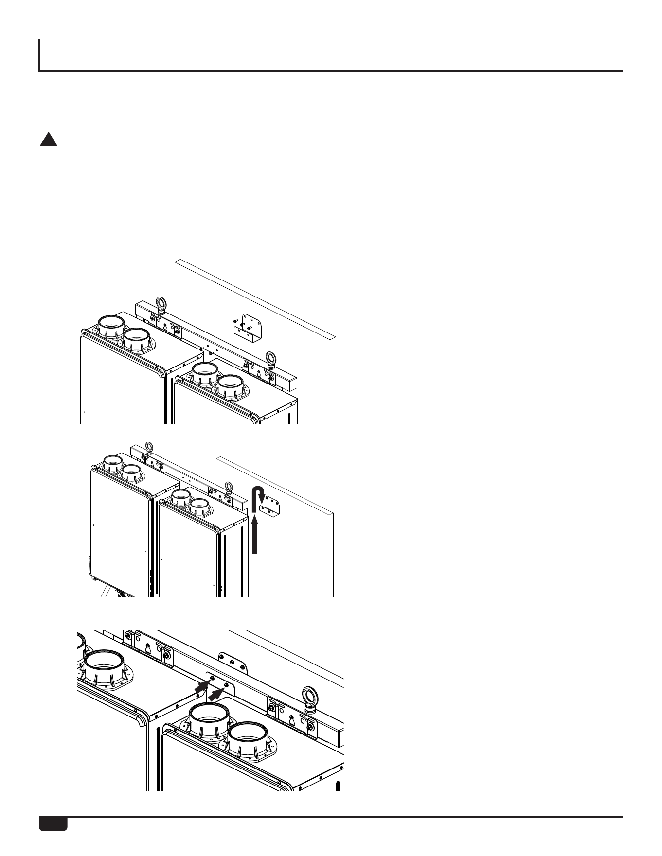
Securing Wall Mount Racks
Wall Mount Models
RTR-WM220 RTR-WM330
!
WARNING:
The wall must be cabable of carrying the operating
weight of the installed RTR System. Consult a
structural engineer for structural analysis of the wall
and appropriate hanging methods before attempting
to hang the RTR System. Failure to comply with
the above requirement could result in substantial
property damage, severe personal injury or death.
• Identify the installation location and confirm that the
installation will meet all required clearances.
• Anchorage details the contractor or engineer on record
for the building shall consult with a licensed structural
engineer for all anchorage of equipment not called out
in this manual.
• In the event of a conflict or inconsistency between
items indicated in this manual regarding code require-
ments, the more stringent standard shall prevail.
• Using the holes in the wall bracket, Securely attach the
rack to the wall. Ensure that the attachment strength
is sufficient.
• Reference local codes regarding minimum concrete
thickness and use appropriate expansion anchors that
is capable supporting the RTR weight .
RTR-WM220 & RTR-WM330
28
SECURING THE RACKS
!
WARNING:
The wall must be cabable of carrying the operating
weight of the installed RTR System. Consult a
structural engineer for structural analysis of the wall
and appropriate hanging methods before attempting
to hang the RTR System. Failure to comply with
the above requirement could result in substantial
property damage, severe personal injury or death.
• Identify the installation location and confirm that the
installation will meet all required clearances.
• In the event of a conflict or inconsistency between
items indicated in this manual regarding code require-
ments, the more stringent standard shall prevail.
1. Using the holes in the wall hanging
bracket, securely attach the bracket
level to the wall. Ensure that the attach-
ment strength is sufficient.
2. Lift the wall hanging rack , and insert
the top of the frame into the bracket.
3. Secure the front of the bracket to the
front of the wall hanging frame with a
#12 x 3/4 drill point screw.
Securing Wall Hung Racks
29
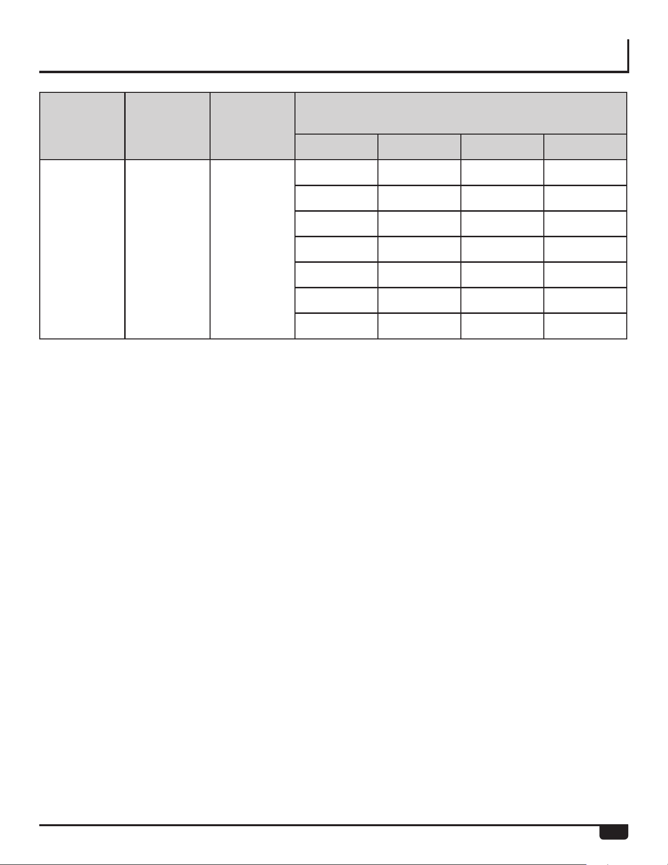
VENTING OPTIONS
• Refer to the high efficiency commercial condens-
ing tankless water heater use and care manual and
common vent installation guide for specific details
regarding vent installation option and installation.
• Venting components are packaged and shipped
separately from the pre-assembled Rack for field
assembly of the vent system by the contractor.
Venting
Options
Exhaust Vent
Material
Intake Vent
Material
Max. Vent Lenght
Number of
water heaters
6” Common
Vent
8” Common
Vent
10” Common
Vent
Common
Venting
System*
PPs PPs
2
70' (21 m) 100' (30 m) 100' (30 m)
3
50' (15 m) 100' (30 m) 100' (30 m)
4
40' (12 m) 100' (30 m) 100' (30 m)
5
N/A 100' (30 m) 100' (30 m)
6
N/A 78' (25 m) 100' (30 m)
7
N/A 55' (17 m) 100' (30 m)
8
N/A 43' (13 m) 100' (30 m)
* Approval Common Venting Only
30
RELIEF VALVE PIPING
PIPING FOR MULTIPLE RACKS
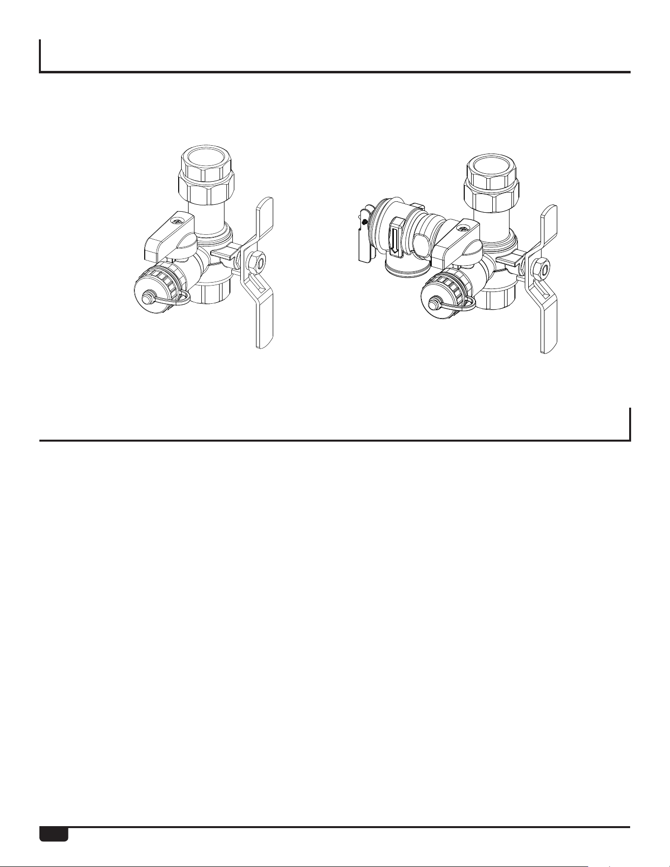
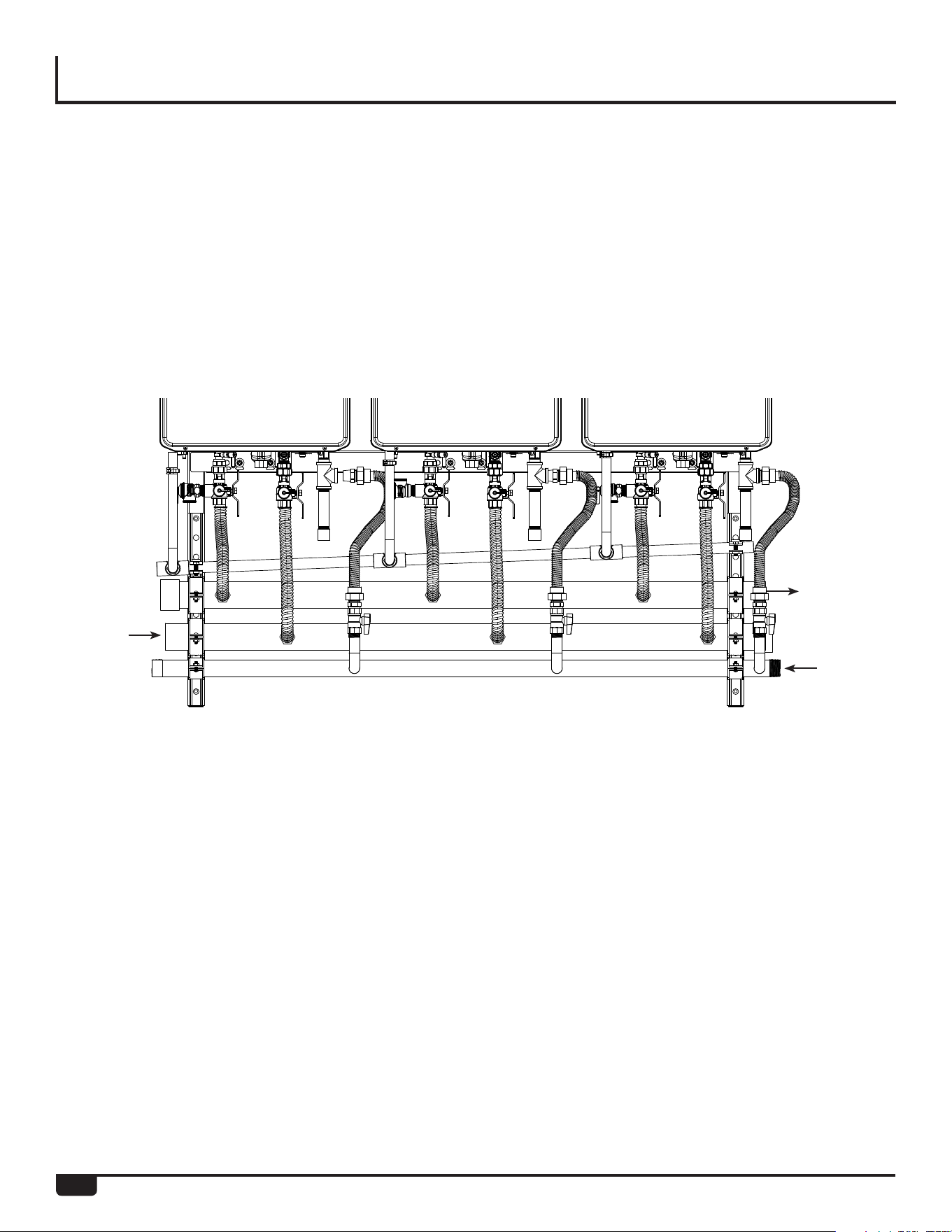
Each Rheem tankless water heater on the RTR comes installed with Isolation valves and a pressure relief valve. Refer to
the installation and operation manual for more information on proper piping for the relief valve drain.
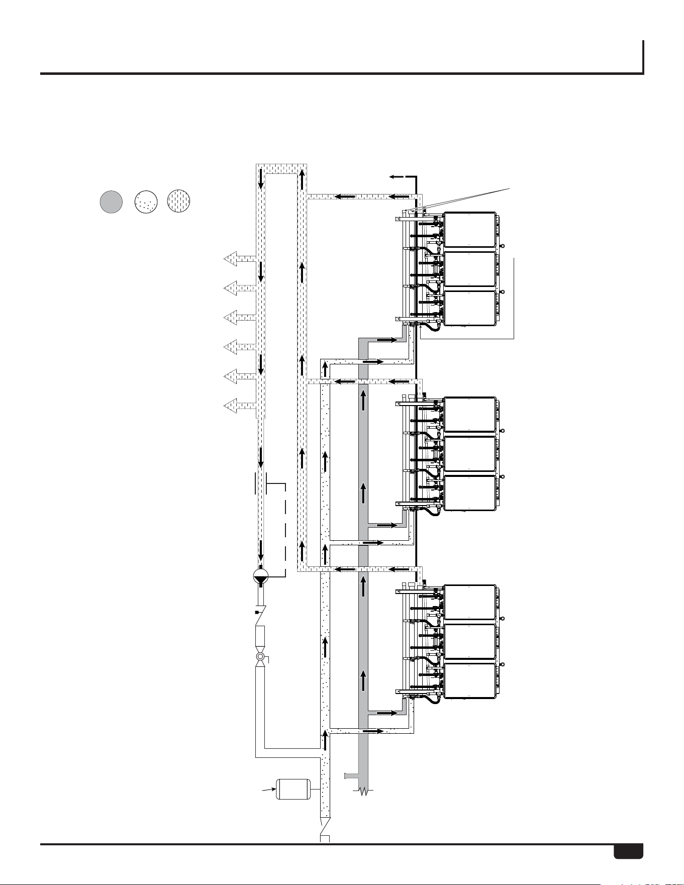
Multiple rack systems should be installed in parallel
using a secondary manifold from the building cold and
hot water supply. Reference the drawing on the follow-
ing page for guidance on plumbing multiple racks in a
parallel piping system.
A low pressure gas regulator must be installed prior to
the rack system. Note the maximum cumulative input for
the system when sizing the gas regulator.
Use common plumbing practice and reference all appli-
cable codes when sizing the secondary manifolds and
gas regulator.
Cold Side Hot Side
31
PARALLEL PIPING DRAWING
Rack Parallel Piping System
Condensate
Drain Line Route
per local code
Hot Water Supply Line Hot Water Supply Line
Cold Water Supply Line
Gas Supply Line Gas Supply Line
Cold Water Supply Line
Expansion Tank
Hot Water Supply Line
Hot Outlets
Hot Water
Cold Water
Gas
Return Line
Use common plumbing
practice in sizing secondary
water and gas manifolds
Typical for each rack:
Field supplied end caps.
Refer to rack spec sheet for size.
Must be approved for potable water
32
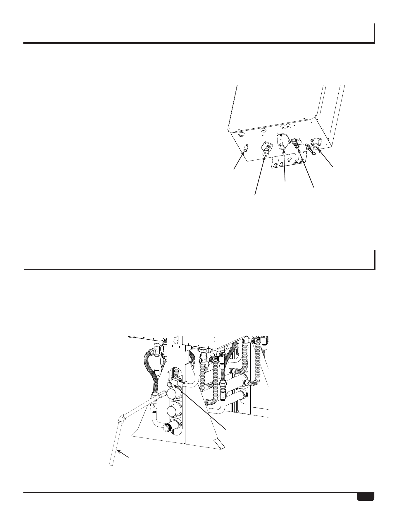
END CAPS / CONNECTIONS
End caps are to be field supplied and to be of the following
materials:
• Cold water cap - Brass or Copper
• Hot water cap - Brass or Copper
• Gas cap - black iron
Once flow direction and gas supply side is determined
the other (opposite) side of the manifold must be
capped. See the example below.
Leak check the capped ends of the manifolds.
Cap
Cap
Cap
Cold In
Gas In
Hot Out
33
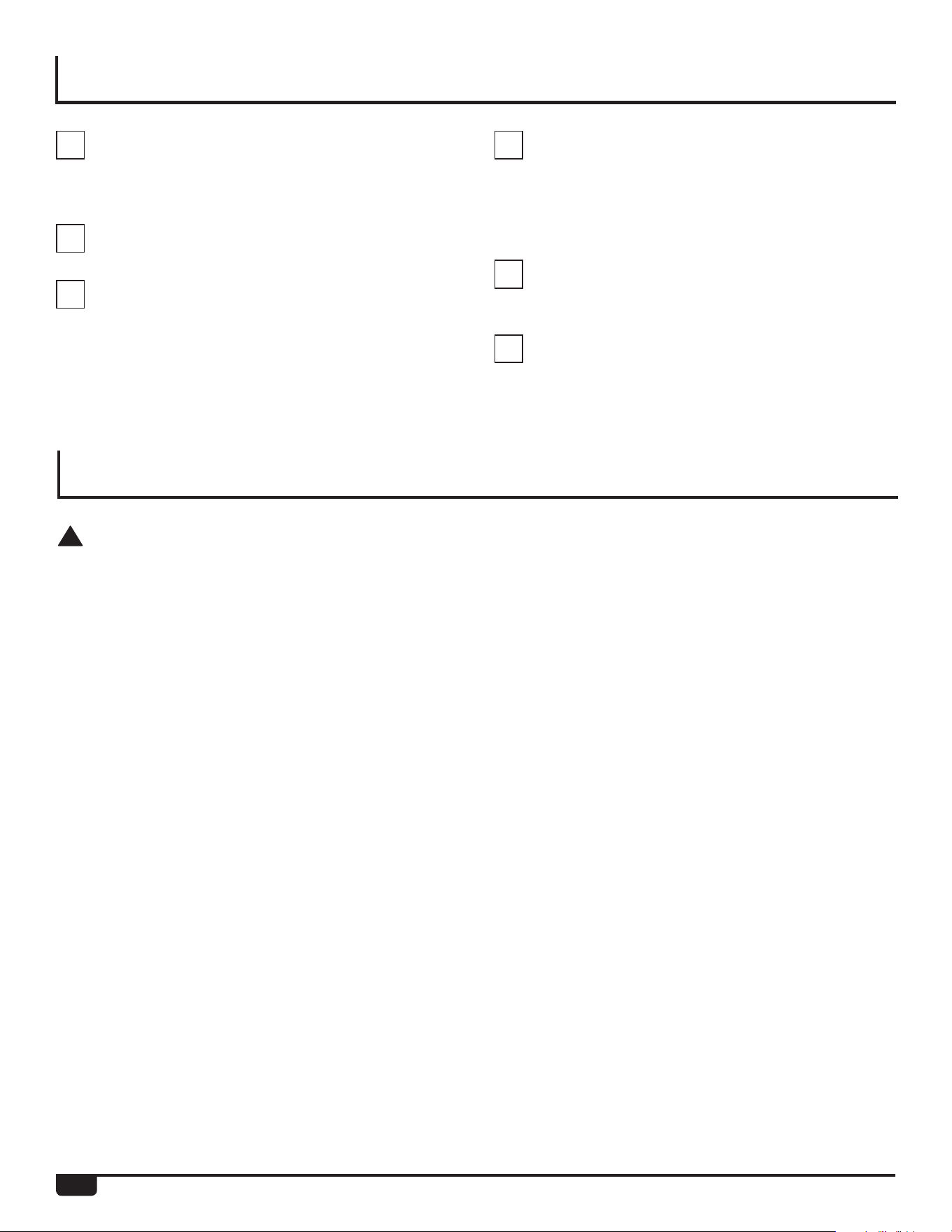
CONDENSATE DRAIN
CONDENSATE MANIFOLD
Each Rheem tankless water heater has a condensate drain
outlet on the bottom of the unit. A drain line must be con-
nected to each water heater.
Freestanding rack systems will include a prefabricated con-
densate manifold (not shown in diagram).
Condensate piping shall be CPVC or PVC material and
shall not be smaller than the drain connection on the appli-
ance.
Components of the condensate drainage shall be of CPVC
or PVC material. All components shall be selected for the
pressure and temperature rating of the installation.
Where the drain pipes from more than one unit are mani-
folded together for condensate drainage, the pipe or tubing
shall be sized in accordance with an approved method as
dictated by local codes.
Condensate must be disposed of according to local codes.
Condensate Manifolds are installed above the water manifolds.
Piping Diagram for Basic
Installation
The condensate drain pipe (along its entire length) must be
at least the same diameter as the drain line.
Condensate drain must be sloped downward at 2 degrees from the rack system.
Condensate must be disposed of per local codes.
Field Supplied PVC
Condensate
Drain Line
Hot Water
Outlet
Cold
Water
Inlet
Gas
Connection
Wiring
Condensate
Manifold 3/4”
Connection
SCALE 0.250
34
CHECKLIST FOR PLUMBING
INSTALLATION OF GAS SUPPLY
Safety Check
Purge the water line of all debris and air by closing
the hot water isolation valve and opening the cold
water isolation valve and its drain. Debris will damage
the water heater. Use a bucket or hose if necessary.
Ensure that hot and cold water lines are not
crossed to the unit and are leak free.
Ensure that a pressure relief valve is installed with a
rating that exceeds the BTU input of the water heater
model. Refer to the rating plate on the side of the
water heater for BTU input.
Clean the inlet water filter by closing the cold and
hot water inlet isolation valves. Put a bucket under
the filter at the bottom of the water heater to catch
any water that is contained inside the unit. Unscrew
the water filter. Rinse the filter to remove any debris.
Install the filter and open the isolation valves.
Check for proper water pressure to the water heater.
Minimum water pressure is 50 psi. Rheem recom-
mends 60-80 psi for maximum performance.
Ensure any issues regarding water quality have been
properly addressed.
!
WARNING:
A licensed professional must install the gas supply.
1. Turn off 120v power supply.
2. Turn off the gas.
3. Gas is flammable. DO NOT smoke or provide other
ignition sources while working with gas.
4. DO NOT turn on the water heater or gas until all
fumes are gone.
• Check the type of gas and the gas inlet pressure before
connecting the water heater. If the water heater is not of
the gas type that the building is supplied with, DO NOT
connect the water heater. Contact the dealer for the prop-
er unit to match the gas type.
• Check the gas supply pressure immediately upstream
at a location provided by the gas company. Supplied
gas pressure must be within the limits shown in the
Specifications section of this manual with all gas appli-
ances operating.
• Before placing the appliance in operation, all joints
including the heater must be checked for gas tightness
by means of leak detector solution, soap and water, or an
equivalent nonflammable solution, as applicable. (Since
some leak test solutions, including soap and water, may
cause corrosion or stress cracking, the piping shall be
rinsed with water after testing, unless it has been deter-
mined that the leak test solution is non corrosive.)
• Use approved connectors to connect the unit to the gas
line. Purge the gas line of any debris before connection
to the water heater.
• Any compound used on the threaded joint of the gas
piping shall be a type that resists the action of liquefied
petroleum gas (propane/ LPG).
• The gas supply line shall be gas tight, sized, and so
installed as to provide a supply of gas sufficient to meet
the maximum demand of the heater and all other gas
consuming appliances at the location without loss of
pressure.
Information
• If in doubt about the size of the gas line, refer to an
approved pipe sizing chart
35
ELECTRICAL CONNECTIONS
!
WARNING:
DO NOT use an extension cord or an adapter plug
with this appliance.
The water heater must be electrically grounded in
accordance with local codes and ordinances or, in
the absence of local codes, in accordance with the
National Electrical Code, ANSI/NFPA 70.
Indoor water heaters are equipped with a three-prong
(grounding) plug for your protection against shock
hazard and should be plugged directly into a properly
grounded three-prong receptacle. DO NOT cut or
remove the grounding terminal from this plug.
DO NOT rely on the gas or water piping to ground the
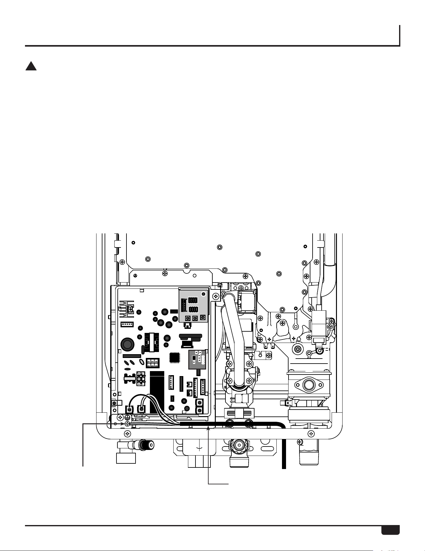
water heater. A screw is provided in the junction box for the
grounding connection.
The water heater requires 120 VAC, 60 Hz power from a
properly grounded circuit.
If using the 5 foot long power cord, plug it into a standard
3 prong 120 VAC / 60 Hz properly grounded wall outlet.
On outdoor models, a disconnect switch must be provided
and installed for the incoming 120 VAC power. It should be
a type that is suitable for outdoor use. Check the National
Electrical Code, ANSI/NFPA 70 and your local codes for a
proper switch type to use in your area.
The wiring diagram is located on the Technical Sheet
attached to the inside of the front cover of the water heater.
ON
1
2
3
4
ON
OFF
ON
1
2
3
4
ONOFF
1
2
3
4
1
2
3
4
DIP1
DIP2
MIN
MAX
ADJ
LED
Ground
Screw
Connection
120 V Wiring
Blue or Black wire = Hot
Brown or White wire = Neutral
Green = Ground
36
ELECTRICAL INDOOR (PRE-WIRED ELECTRIC ASSEMBLY)
IMPORTANT:
Refer to the Specifications sections in this manual
for electrical requirements.
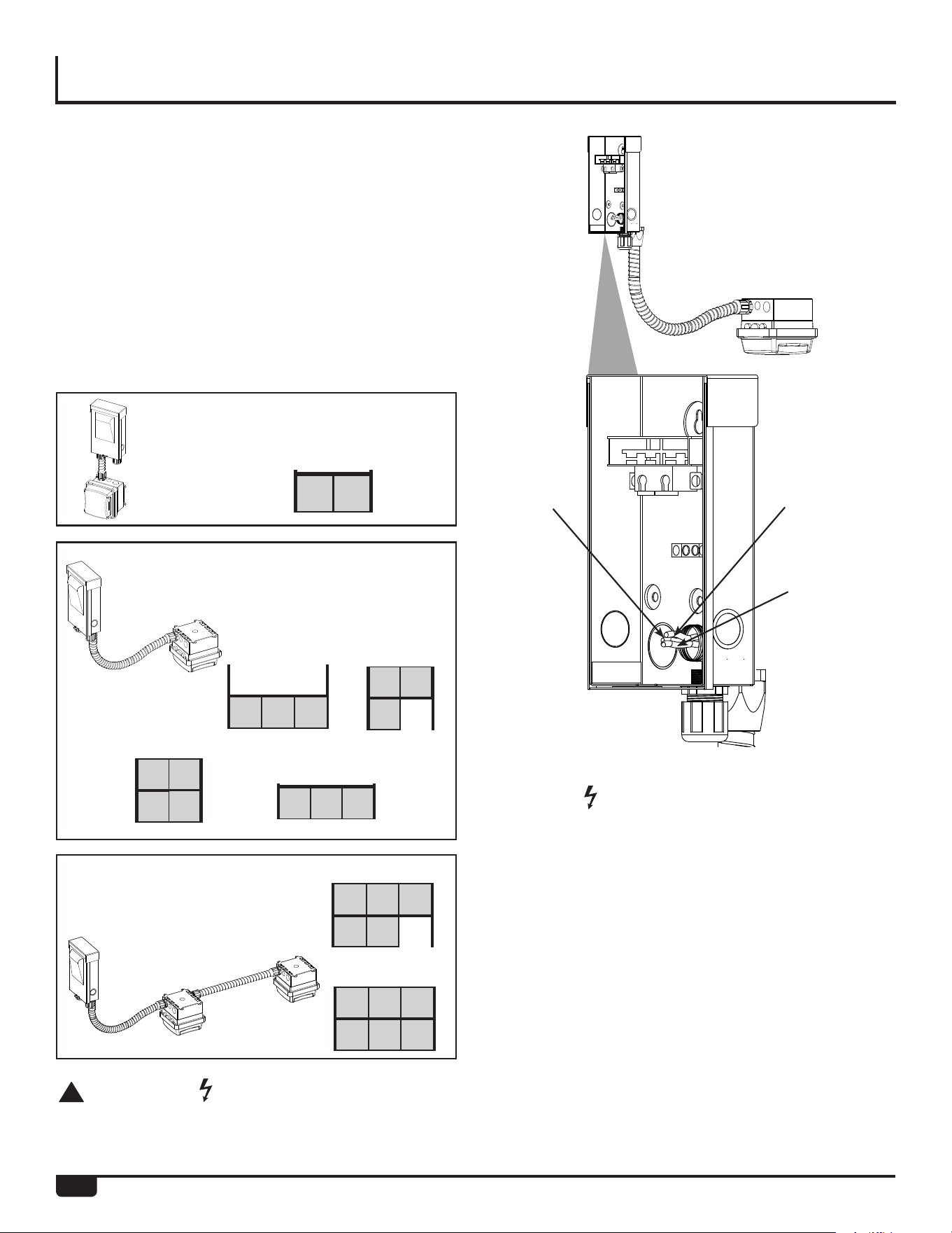
1. Locate gang box on side of RTR frame.
2. Remove the 2 screws securing front panel to
gang box.
3. Remove front panel.
4. Run building supplied electrical wiring and
conduit to gang box.
5. Connect building wiring to the 3 12AWG, THHN
wires, Hot (Black), Neutral (White), and Ground
(Green).
6. Reinstall front panel to gang box using 2 screws.
Electrical Assemblies are installed on the middle rack frame of
the following racks for single point electrical connection.
Interior Models Available
With Pre-Wired Electrical
Assemblies:
4 Unit Electrical Assembly
with 20A, 125V, 2-Pole,
3 Wire Grounding
Receptacles.
2 Unit Electrical Assembly
with 20A, 125V, 2-Pole, 3 Wire
Grounding Receptacles.
6 Unit Electrical Assembly
with 20A, 125V, 2-Pole, 3 Wire
Grounding Receptacles.
RTR-FS630 RTR-FS412
RTR-FS623
RTR-FS633
RTR-FS422
!
WARNING :
Shut off building supply power prior to connecting to
RTR electrical assembly. Failure to do so may result
in property damage, bodily harm, or death.
RTR-WM330
NOTICE :
DO NOT connect the tankless water heaters to
the outlet located under the center rack prior to
connecting building power supply to the rack
electrical gang box. Doing so may cause damage to
the PC Boards of the tankless water heaters.
Green
(Ground)
Black
(Hot)
White
(Neutral)
37
ELECTRICAL INDOOR (PRE-WIRED ELECTRIC ASSEMBLY)
IMPORTANT:
The outlet is designed for use with Rheem Tankless
Water Heaters only. DO NOT insert power cords
belonging to other appliances or electrical sources
into the outlet.
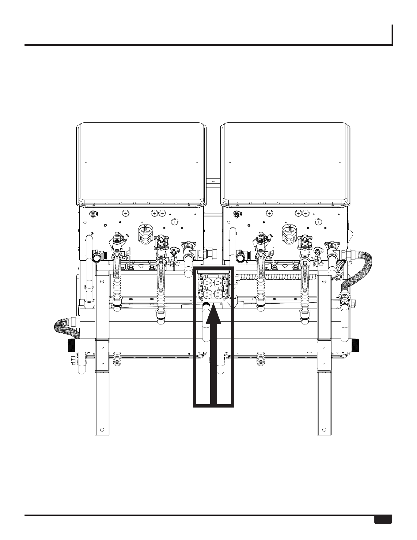
7. Once the building electrical power supply has
been wired to the rack system, plug the indoor
units into the outlet located under the center
rack frame as shown below.
Outlet is designed for use by
Rheem Tankless Water Heaters only
38
IMPORTANT:
Refer to the Specifications sections in this manual
for electrical requirements.
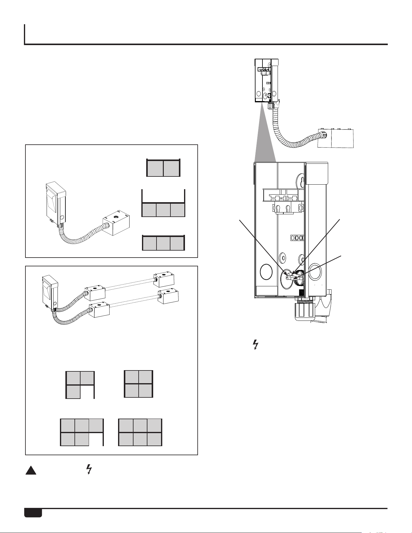
1. Locate gang box on side of RTR frame.
2. Remove the 2 screws securing front panel to
gang box.
3. Remove front panel.
4. Run building supplied electrical wiring and
conduit to gang box.
5. Connect building wiring to the 3 12AWG, THHN
wires, Hot (Black), Neutral (White), and Ground
(Green).
6. Reinstall front panel to gang box using 2
screws.
Outdoor Models Available
With Pre-Wired Electrical
Assemblies:
Side-Side configuration - Electrical
assembly with 20A, 125V, 2-pole,
3 Wire Grounding Receptacles.
Back-Back configuration - Electrical assem-
bly with 20A, 125V, 2-pole, 3 Wire Grounding
Receptacles.
RTR-FS630
RTR-WM2
RTR-FS412
RTR-FS623 RTR-FS633
RTR-FS422
!
WARNING :
Shut off building supply power prior to connecting to
RTR electrical assembly. Failure to do so may result
in property damage, bodily harm, or death.
RTR-WM330
NOTICE :
DO NOT connect the tankless water heaters to
the outlet located under the center rack prior to
connecting building power supply to the rack
electrical gang box. Doing so may cause damage to
the PC Boards of the tankless water heaters.
Green
(Ground)
Black
(Hot)
White
(Neutral)
ELECTRICAL OUTDOOR
(PRE-WIRED ELECTRIC
ASSEMBLY)
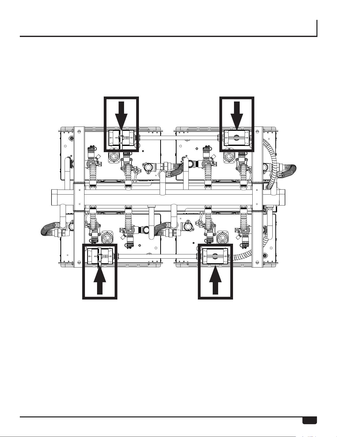
39
IMPORTANT:
The outlet is designed for use with Rheem Tankless
Water Heaters only. DO NOT insert power cords
belonging to other appliances or electrical sources
into the outlet.
7. Once the building electrical power supply has
been wired to the rack system, plug the indoor
units into the outlet located under the center
rack frame as shown below.
Outlet is designed for use by
Rheem Tankless Water Heaters only
ELECTRICAL OUTDOOR
(PRE-WIRED ELECTRIC
ASSEMBLY)
40
MULTIPLE UNITS SET-UP
All of the water heaters are electronically con nected using
the Manifold Controller system. The EcoNet Translator kits
can electronically connect up to 20 water heaters.
The temperature setting for all of the connected water
heaters is controlled by the remote controller connected to
the water heater with the Manager indicated by 01. Remote
controllers connected to the other units will provide mainte-
nance codes for their respec tive units.
Additional remote controllers shall not be installed on the
rest of the water heater(s) except the Manager indicated
by 01.
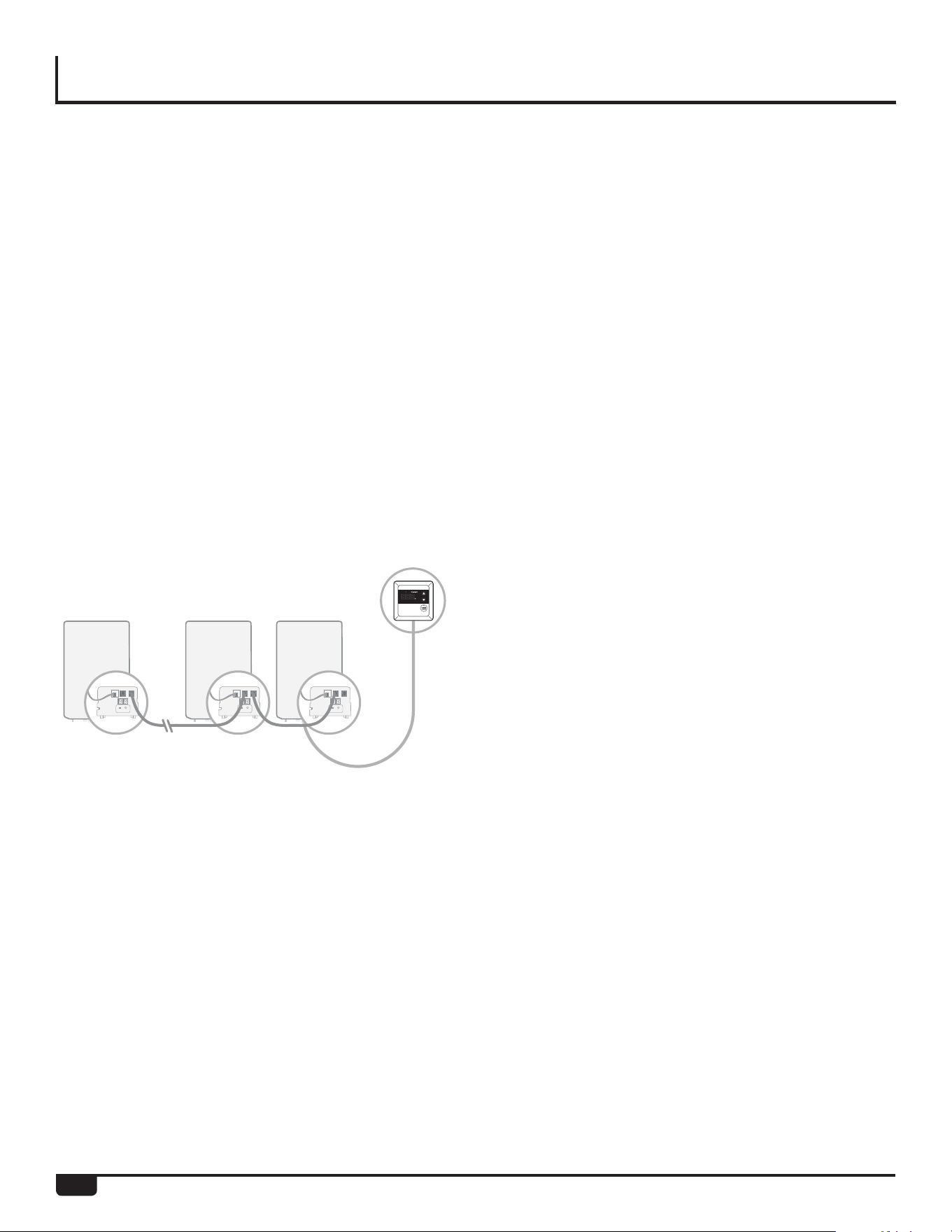
If you have multiple tankless gas water heaters manifolded together, follow the next steps to setup your system.
1. Install Water Sensor and Translator in each unit to be
manifolded.
2. Make sure all DIP switches on the Water Heater Control
Board are in the OFF position.
3. Connect manifolded units serially with the provided
RJ25 cable usign both / any of the ports on the Manifold
Controller.
4. On unit 01, enter the setup menu by pressing the two
buttons on the Manifold Controller simultaneously for 5
seconds. If successful, you will see “1” instead of “01” on
the display.
5. Repeat step 4 on each water heater, pressing the right
button to assign sequential numbers to each unit (01,
02, 03, up to 20). The menu will exit and changes will be
saved after 10 seconds if no buttons are pressed.
6. On unit 01, enter the setup menu again, pressing the
left button until it reads “2”. Press the right button until
the display reads the total number of units manifolded
together (2-20).
7. Connect the Remote Control included with the water
heater to unit 01, which will allow you to control/set/view
the water outlet temperature of all units.
Once all units on the manifold are numbered correctly, the
configuration will be completed and your system is ready
for operation using the Remote Control or EcoNet App.
Setup For Multiple Manifolded Units
AP18291
AP18278
AP18291
AP18278
AP18291
AP18278

41
FINAL CHECKLIST
The water heater is not subject to corrosive
compounds in the air.
The water supply does not contain chemicals or exceed
total hardness that will damage the heat exchanger.
Clearances from the water heater unit are met.
Clearances from the vent termination and air intake
are met.
For indoor models, ensure you have used the correct
venting products for the model installed and that you
have completely followed the venting manufacturer’s
installation instructions and these installation instruc-
tions.
For indoor models, verify that the vent system does not
exceed the maximum length for the number of elbows
used.
Purge the water line of all debris and air by closing the
hot water isolation valve and opening the cold water
isolation valve and its drain. Debris will damage the
water heater. Use a bucket or hose if necessary.
Ensure that hot and cold water lines are not crossed
to the unit and are leak free.
A manual gas control valve has been placed in the gas
line to the water heater.
Ensure that a pressure relief valve is installed with a
rating that exceeds the BTU input of the water heater
model. Refer to the rating plate on the side of the water
heater for BTU input.
Clean the inlet water filter by closing the cold and hot
water inlet isolation valves. Put a bucket under the filter
at the bottom of the water heater to catch any water
that is contained inside the unit. Unscrew the water
filter. Rinse the filter to remove any debris. Install the
filter and open the isolation valves.
Check the gas lines and connections for leaks.
Confirm that the gas inlet pressure is within limits.
Confirm that the water heater is rated for the gas type
supplied.
Confirm that the electricity is supplied from a 120 VAC,
60 Hz power source, is in a properly grounded circuit,
and turned on.
Verify the temperature controller is functioning properly.
Verify that DIP Switch adjustments are is set correctly for
your altitude.
Verify the system is functioning correctly by connecting
your manometer to the gas pressure test port on the
water heater. Operate all gas appliances in the home or
facility at high fire. The inlet gas pressure at the water
heater must not drop below that listed on the rating plate.
DO NOT introduce toxic chemicals such as those used
for boiler water treatment to the potable water used for
space heating.
If the water heater is not needed for immediate use, then
drain the water from the heat exchanger.
Install the front panel.
Explain to the customer the importance of not blocking
the vent termination or air intake.
Explain to the customer the operation of the water heater,
safety guidelines, maintenance, and warranty.
The installation must conform with local codes or, in the
absence of local codes, with the National Fuel Gas Code,
ANSI Z223. 1/NFPA 54, or the Natural Gas and Propane
Installation Code, CSA 8149.1. If installed in a manu-
factured home, the installation must conform with the
Manufactured Home Construction and Safety Standard,
Title 24 CFR, Part 3280 and/or CAN/SCA Z240 MH
Series, Mobile Homes.
Inform the consumer if the isolation valves are not
installed or if a water softening system is not installed.
Leave the entire manual taped to the water heater (indoor
models), temperature controller (outdoor models), or give
the entire manual directly to the consumer.
Is the main gas valve to the water heater open?
Is the fuse in place or is the breaker turned on?
Does the water heater’s electronic ignition light?
Is the water temperature set to a safe temperature?
Is the water heater connected to a floor drain?
Is the water heater properly vented to the outside?
Is the water heater installed in a safe location away
from flammable materials and/or freezing conditions?
Pre-operating Checklist
42
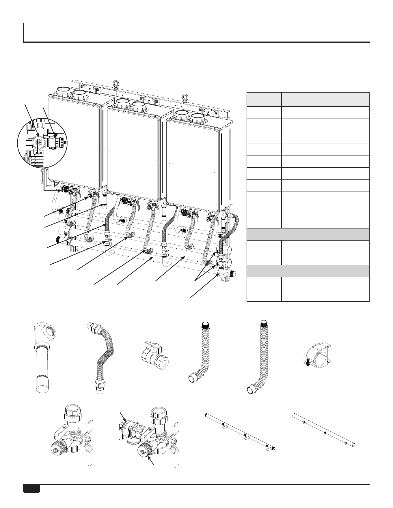
REPLACEMENT PARTS
RTR Replacement Parts Reference Numbers
All RTR-WH
Ref.# Description
1 Dirt Leg
2 Gas Flex Line Assembly
3 Gas Shut-Off Valve
4 Hot Water Flex Line
5 Cold Water Flex Line
6 Cush Clamp 2.63ID
7 Cush Clamp 1.90ID
8 Cold Isolation Valve
9 Hot Isolation Valve
10 Pressure Relief Valve
RTR-WH3
11 Manifold, Gas - 3WM
12 Manifold, Water - 3WM
RTR-WH2
13 Manifold, Gas - 2WM
14 Manifold, Water- 2WM
1
1
8
2
3
4
5
11 / 13
12 / 14
7
6
2
3 4
8
10
9
5
6/7
11/13
12/14
9
10
43
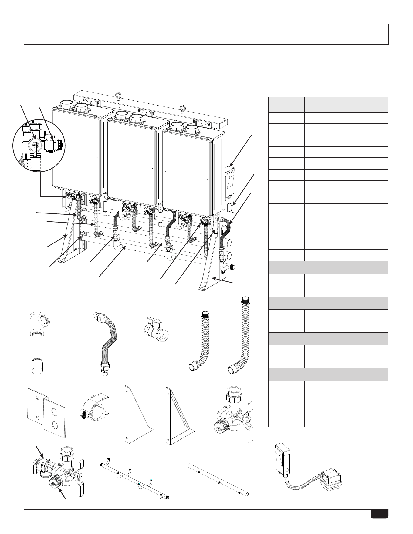
REPLACEMENT PARTS
RTR Replacement Parts Reference Numbers
ALL RTR-WM / RTR-FS
Ref.# Description
1 Dirt Leg
2 Gas Flex Line Assembly
3 Gas Shut-Off Valve
4 Hot Water Flex Line
5 Cold Water Flex Line
6 Wall Bracket
7 Cush Clamp 2.63 ID
8 Cush Clamp 1.90 ID
9 Left Leg
10 Right Leg
11 Cold Isolation Valve
12 Hot Isolation Valve
13 Pressure Relief Valve
RTR-WM3
14 Manifold, Gas
15 Manifold, Water
RTR-WM2
16 Manifold, Gas
17 Manifold, Water
RTR-FS6
18 Manifold, Gas
19 Manifold, Water
RTR-FS4
20 Manifold, Gas
21 Manifold, Water
22 Electrical - 4 Connections
23 Electrical - 8 Connections
1
2
3
4
22 / 23
6
2
3
9
5
4
11
1
10
14 / 16 / 18 / 20
15 / 17 / 19 / 21
7 / 8
5
6
7 / 8
14 / 16 / 18 / 20
22 / 23
15 / 17 / 19 / 21
9
10
11
13
12
12
13
44
REPLACEMENT PARTS
RTR Replacement Parts Reference Numbers
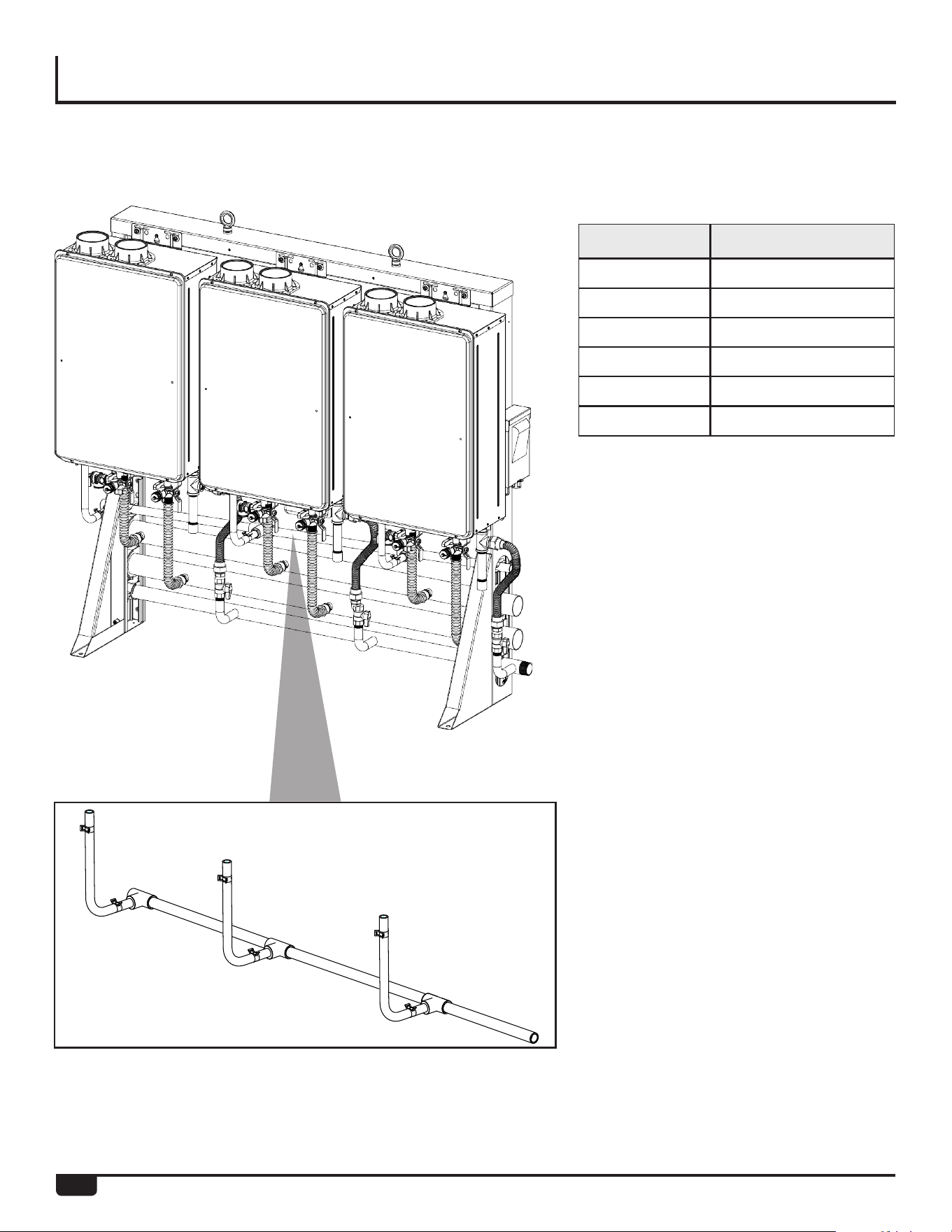
Condensate Manifold
Rack Description
RTR-WH3 3 Connections - In-Line
RTR-WH2 2 Connections - In-Line
RTR-WM3 3 Connections - In-Line
RTR-WM2 2 Connections - In-Line
RTR-FS6 6 Connections
RTR-FS4 4 Connections
45
REPLACEMENT PARTS
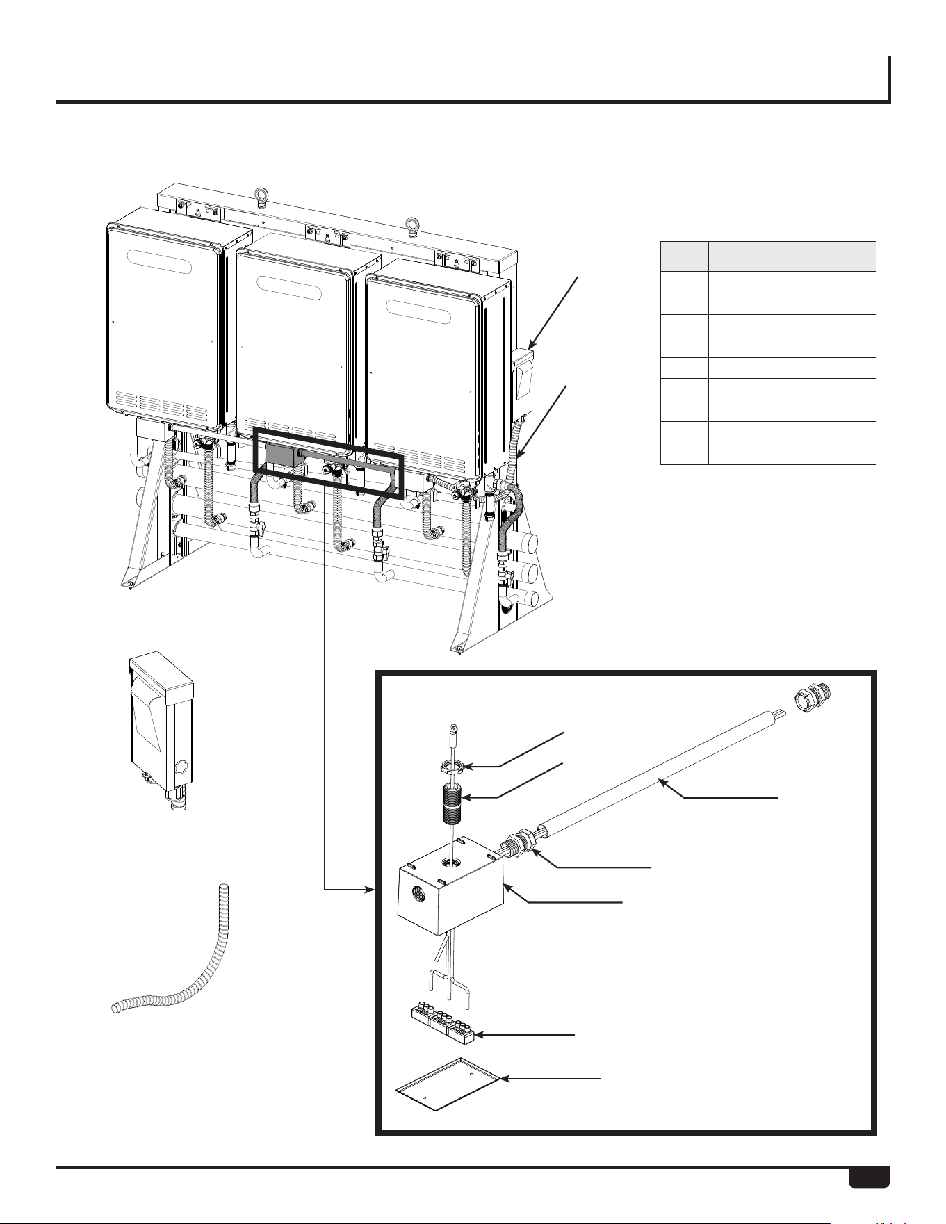
RTR Replacement Parts Reference Numbers
1
4
1
4
7
8
6
5
9
2
3
Outdoor Models
Electrical Assemblies
Ref.# Description
1 Electrical Connections
2 Weatherproof Box
3 Box Cover
4 Flexible Conduit
5 Conduit Steel Pipe
6 3-Port Connector
7 Nipple
8 Lock Nut with Gasket
9 Conduit Adaptor

46
Call for Assistance
1. All questions, adjustments, repairs, and/or routine mainte-
nance should be directed to your installer, plumbing contrac-
tor, or licensed service agent. If your contacts have moved
or are not available, please refer to the telephone directory,
commercial listings, or local utility company for qualified ser-
vice assistance.
2. If your problem has not been solved to your satisfaction,
contact the Rheem National Service Department at the fol-
lowing address:
Rheem
National Service Department
800 Interstate Park Drive
Suite 700
Montgomery, AL 36109
Phone: 1-866-720-2076
When contacting the manufacturer, the following information
will be requested:
A. Model and serial number. (See page 8 or the ratings plate
on the side of the water heater.)
B. Address where the water heater is located.
C. Name and address of installation contractors (page 8) and
all qualified service companies that have worked on the
water heater.
D. Original installation date. (See page 8.)
E. Dates any service or preventive maintenance was per-
formed.
F. Details of the persisting problem.
G. List of businesses that have tried to fix this problem, along
with dates of service.
IF YOU NEED SERVICE

47
LIMITED WARRANTY
GENERAL
This Limited Warranty is only available to the original owner of the water heater at the original installation location. This Limited
Warranty is not transferable.
Rheem Sales Company, Inc. (Rheem) warrants this tankless gas water heater, and its component parts, to be free from
defects in materials and manufacture, under normal use and service, for the Applicable Warranty Period specified below. At its
option, Rheem will repair or replace the defective water heater, or defective component part(s), in accordance with the terms of
this Limited Warranty, if it fails in normal use and service during the Applicable Warranty Period. The replacement water heater
must be manufactured by Rheem under one of the covered brand names. The replacement component part(s) must be Rheem
authorized component part(s). The replacement unit will be warranted only for the unexpired portion of the original unit’s Applicable
Warranty Period.
Rheem strongly recommends that this tankless water heater be installed by a contractor that is licensed, state qualified and
trained on Rheem’s tankless products because improper installation may invalidate warranty coverage.
EFFECTIVE DATE
The Effective Date of warranty coverage (or the beginning of the Applicable Warranty Periods) is the date of the original installation
of the water heater, if properly documented. Otherwise, it is the date of manufacture of the water heater plus ninety (90) days.
APPLICABLE WARRANTY PERIODS: The Applicable Warranty Period depends on the type of installation, as described
below:
Commercial: any installation that is not a single family dwelling
Five (5) years from the Effective Date for the heat exchanger, five (5) years from the Effective Date for the component parts, and
one (1) year from the Effective Date for certain labor as described under the heading, LABOR, SHIPPING AND PROCESSING
COST.
Commercial: with recirculation, controlled loop
Five (5) years from the Effective Date for the heat exchanger, five (5) years from the Effective Date for the component parts, and
one (1) year from the Effective Date for certain labor as described under the heading, LABOR, SHIPPING AND PROCESSING
COST. Provided that the recirculation system is an on demand type system or the pump is controlled with a temperature sensor
(aquastat) and timer.
Chart for Recommended Water Quality Levels
pH (Total Dissolved Solids) TDS Free Carbon Dioxide (CO
2
) Total Hardness Aluminum Chlorides Copper Iron Manganese Zinc
6.5–8.5 Up to 500 mg/L Up to 15 mg/L Up to 200 mg/L 0.05 to 0.2 mg/L Up to 250 mg/L Up to 1.0 mg/L Up to 0.3 mg/L Up to 0.05 mg/L Up to 5 mg/L
Cited reference: National Secondary Drinking Water Regulations
For the RHEEM® Commercial Tankless Gas Water Heaters.

48
LIMITED WARRANTY
Commercial: with recirculation, uncontrolled loop
Three (3) years from the Effective Date for the heat exchanger, three (3) years from the Effective Date for the component parts, and
one (1) year from the Effective Date for certain labor as described under the heading, LABOR, SHIPPING AND PROCESSING
COST, if the water heater is installed in a system in which the water is re-circulated using a continuously operating pump.
WARRANTY EXCLUSIONS
This Limited Warranty will not cover:
a) Damages, malfunctions or failures resulting from:
1. Installation of the water heater in environments in which water quality levels DO NOT fall within the ranges
listed in the table below:
b) Operating the water heater in a corrosive or contaminated atmosphere, including without limitation damages,
malfunctions or failures caused by lime, mineral build-up, or scale.
c) Service trips to your business to teach you how to install, use, or maintain this water heater or to bring
the water heater installation into compliance with local building codes and regulations or manufacturer’s
installation requirements.
d) Water heater unit installed for use in: spa or pool heating; a recreational vehicle; a boat or any other
watercraft.
e) Water heater unit installed in any circulating system in which the temperature of the incoming water to the
water heater is in excess of 140° f.
f) Water heater unit that is installed in any installation supplying radiant heat, such as in floor, baseboard,
radiators, snow melt or closed loop systems, or any system using glycol or non-potable water.
g) Damages, malfunctions or failures resulting from failure to install the water heater in accordance with
applicable building codes/ordinances or good plumbing and electrical trade practices.
h) Damages, malfunctions or failures resulting from improper installation or failure to operate and maintain the
unit in accordance with the manufacturer’s instructions.
i) Performance problems caused by improper sizing of the water heater or the gas supply line, the venting
connection, combustion air openings, electric service voltage, wiring, or fusing.
j) Damages, malfunctions or failures caused by improper conversion from natural gas to LP gas or LP gas to
natural gas fuel source.
k) Damages, malfunctions or failures caused by operating the water heater with any parts removed or with
modified, altered, or unapproved parts installed.
l) Damages, malfunctions or failures caused by abuse, accident, fire, flood, freeze, lightning, acts of God and the
like.
m) Heat exchanger failures (leaks) caused by operating the water heater in a corrosive or contaminated
atmosphere or damages, malfunctions or failures caused by lime, mineral build-up, or scale.
n) Damages, malfunctions or failures caused by operating the unit at water temperatures exceeding the
maximum setting of the operating, or high limit, control.
o) Heat exchanger failures caused by operating the water heater when it is not supplied with potable water, free
to circulate at all times.
p) Damages, malfunctions or failures caused by subjecting the heat exchanger to pressures, or firing rates,
greater than those shown on the rating label.
q) Damages, malfunctions or failures resulting from the use of any attachment, including any energy saving
device, not authorized by Rheem.
r) Units installed outside the fifty states (and the District of Columbia) of the United States of America and
Canada.
s) Units removed from the original installation location and reinstalled elsewhere.
t) Units that have had their rating labels altered, tampered with, or removed. A water heater should not be
operated if the rating label is removed.

49
LIMITED WARRANTY
LABOR, SHIPPING, AND PROCESSING COSTS
For one (1) year after the Effective Date, Rheem will cover reasonable labor costs necessary to repair or replace a tankless
water heater or component part that Rheem determines to be defective and covered by this Limited Warranty. The warranty
service must be performed by a contractor that is licensed, state qualified, and trained to install and service Rheem's tankless
water heaters. This Limited Warranty does not cover any labor expenses for general service, inspection, reinstallation, permits,
removal and disposal of the failed water heater or defective component part(s), or updating the installation to meet manufacture
or local code requirements. All such expenses are your responsibility.
Rheem will pay the transportation costs for an “in-warranty” replacement water heater, or “in-warranty” replacement component
part(s), to a convenient delivery point (selected by Rheem) near the place the original water heater, or original component part(s),
is located: such as a local water heater distributor. You must pay any local freight charges, including the cost of returning the failed
water heater, or defective component part(s) to a convenient shipping location (selected by Rheem): such as a local Rheem dis-
tributor.
Rheem does not authorize, recommend, or receive any benefit from any claims processing or similar fees charged by others
to process warranty claims for any water heater or component part(s). Rheem will not reimburse any party for these, or any other,
fees not specifically covered in this Limited Warranty document.
HOW TO OBTAIN WARRANTY CLAIM ASSISTANCE
Any claim for warranty assistance must be made promptly. First, determine if your water heater is “in-warranty” (that is, within the
Applicable Warranty Period). You can determine your unit’s warranty status by adding its Applicable Warranty Period to its date
of installation. However, if you DO NOT have documentary proof of your water heater’s date of installation, your unit’s warranty
status will be based on its date of manufacture as determined from the serial number. Add the Applicable Warranty Period plus
ninety (90) days to the date of manufacture to determine whether the water heater is still covered by this Limited Warranty. You
may also determine your unit’s warranty status by obtaining the complete model number, complete serial number, and date of
installation of your water heater and then accessing the “Warranty Verification” information on Rheem Water Heaters' internet
website (www.rheem.com) or contacting Rheem's Claims Department (telephone (800) 621-5622) during normal business hours
(in the Central Time Zone) to determine if the Applicable Warranty Period has expired.
If your water heater is “in-warranty”, contact the plumber, or mechanical contractor, that installed it for assistance with the
warranty repairs, or replacement, required. Rheem Water Heaters' Technical Service personnel are available to assist you (by tele-
phone at (866) 720-2076) in obtaining “in-warranty” service or to answer your questions about the operation or repair of your water
heater during normal business hours (in the Central Time Zone). Be prepared to provide the plumber, mechanical contractor, or
Rheem Technical Service person you call with the complete model number, the complete serial number, and the date of installation
of your water heater in addition to an explanation of your water heater problem.
If an exact replacement is not available, Rheem will provide you with the current model of your water heater, or component
part(s), or a replacement unit with comparable operating features. If government regulations or industry certification or similar
standards require the replacement water heater, or replacement component part(s), to have features not found in the defective
water heater, or the defective component part(s), you will be charged for the difference in price represented by those required
features. If you pay the price difference for those required features and/or to upgrade the size and/or other features available on a
replacement new water heater, you will also receive a complete new Limited Warranty (with the full Applicable Warranty Period)
for the replacement new water heater.
Rheem reserves the right to inspect, or require the return of, the failed water heater or the defective component part(s). Each
“in-warranty” failure water heater must be made available to Rheem (with the rating label and all the component parts intact) in
exchange for the replacement water heater. Each defective “in-warranty” component part to be replaced must be returned to
Rheem in exchange for the replacement component part.
Warranty compensation is subject to validation of “in-warranty” coverage by Rheem Claims Department personnel.
• To obtain warranty compensation for an “in-warranty” water heater failure, you must provide Rheem with the failed water
heater (with the rating label and all the component parts intact) the complete model number and the complete serial number
of the Rheem or Ruud water heater that replaced the failed unit; and the date the original water heater failed. You may also
be required to provide documentary proof of the failed water heaters date of installation to establish its “in-warranty” status.
• To receive warranty compensation for an “in-warranty” defective component part, you must provide Rheem with: the defective
component part; the complete model number and the complete serial number of the Rheem or Ruud water heater from which
the defective component part was removed; and the date the defective component part failed. You may also be required to
provide documentary proof of the date of installation of the Rheem or Ruud water heater from which the defective part was
removed – or the date of purchase of the part (If it was purchased separately) – to establish the “in-warranty” status of the
defective component part.
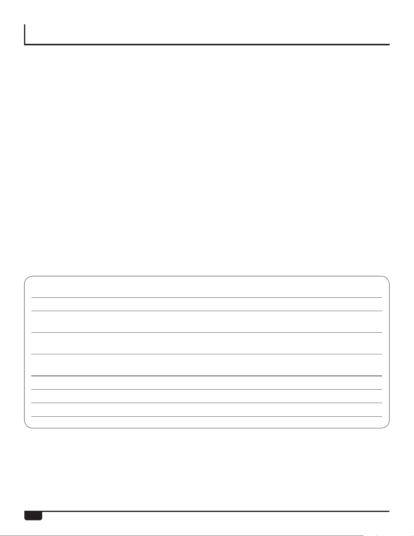
50
LIMITED WARRANTY
Name of Owner:
Owner’s Address:
Name of Plumber/
Mechanical Contractor – Installer:
Address of Plumber/
Mechanical Contractor – Installer :
Telephone Number of Plumber/
Mechanical Contractor – Installer:
Date of Water Heater Installation:
Model Number of Your Water Heater:
Serial Number of Your Water Heater:
• If Rheem determines that the water heater or component part returned to Rheem is free of defects in material and manufac-
ture and/or that it was damaged by improper installation or other cause not covered by this Limited Warranty, the warranty
claim for the product, component part and/or labor maybe denied.
Warranty claim documentation should be mailed promptly to Rheem National Service Department, 800 Interstate Park Drive
Suite 700, Montgomery, Alabama 36109, or in Canada, 125 Edgeware Rd. Unit 1, Brampton, ON, Canada L6Y 0P5
EXCLUSIVE WARRANTY – LIMITATION OF LIABILITY
THIS LIMITED WARRANTY IS THE SOLE AND EXCLUSIVE WARRANTY PROVIDED IN CONNECTION WITH THIS
RHEEM® TANKLESS RACK. No one is authorized to make any other warranties on behalf of Rheem. ANY IMPLIED
WARRANTIES, INCLUDING MERCHANTABILITY, OR FITNESS FOR A PARTICULAR PURPOSE, SHALL NOT EXTEND
BEYOND THE APPLICABLE WARRANTY PERIODS, SPECIFIED PREVIOUSLY. RHEEM’S SOLE LIABILITY, WITH
RESPECT TO ANY DEFECT, SHALL BE AS SET FORTH IN THIS LIMITED WARRANTY, AND ANY CLAIMS FOR
INCIDENTAL OR CONSEQUENTIAL DAMAGES (INCLUDING DAMAGE FROM WATER LEAKAGE) ARE EXCLUDED.
Some states DO NOT allow limitations on how long an implied warranty lasts, or for the exclusion of incidental or consequential
damages, so the above limitations or exclusions may not apply to you.
This Limited Warranty gives you specific legal rights, and you may also have other rights, which vary from state to state.
DO NOT RETURN THIS WATER HEATER OR PART TO RHEEM® WITHOUT A RETURN AUTHORIZATION.
This document is for reference only and does not replace the original warranty document found in the back of the Use
and Care manual provided with the
tankless water heater.
DO NOT RETURN THIS DOCUMENT TO RHEEM®.
KEEP IT WITH YOUR WATER HEATER OR BUSINESS RECORDS.

51
NOTES

52
NOTES